WO2019088047A1 - 電池 - Google Patents
電池 Download PDFInfo
- Publication number
- WO2019088047A1 WO2019088047A1 PCT/JP2018/040193 JP2018040193W WO2019088047A1 WO 2019088047 A1 WO2019088047 A1 WO 2019088047A1 JP 2018040193 W JP2018040193 W JP 2018040193W WO 2019088047 A1 WO2019088047 A1 WO 2019088047A1
- Authority
- WO
- WIPO (PCT)
- Prior art keywords
- portions
- negative electrode
- positive electrode
- current collector
- electrode body
- Prior art date
Links
Images


Classifications
-
- H—ELECTRICITY
- H01—ELECTRIC ELEMENTS
- H01M—PROCESSES OR MEANS, e.g. BATTERIES, FOR THE DIRECT CONVERSION OF CHEMICAL ENERGY INTO ELECTRICAL ENERGY
- H01M10/00—Secondary cells; Manufacture thereof
- H01M10/04—Construction or manufacture in general
- H01M10/0431—Cells with wound or folded electrodes
-
- H—ELECTRICITY
- H01—ELECTRIC ELEMENTS
- H01M—PROCESSES OR MEANS, e.g. BATTERIES, FOR THE DIRECT CONVERSION OF CHEMICAL ENERGY INTO ELECTRICAL ENERGY
- H01M4/00—Electrodes
- H01M4/02—Electrodes composed of, or comprising, active material
- H01M4/64—Carriers or collectors
- H01M4/66—Selection of materials
- H01M4/661—Metal or alloys, e.g. alloy coatings
-
- H—ELECTRICITY
- H01—ELECTRIC ELEMENTS
- H01M—PROCESSES OR MEANS, e.g. BATTERIES, FOR THE DIRECT CONVERSION OF CHEMICAL ENERGY INTO ELECTRICAL ENERGY
- H01M10/00—Secondary cells; Manufacture thereof
- H01M10/05—Accumulators with non-aqueous electrolyte
- H01M10/052—Li-accumulators
- H01M10/0525—Rocking-chair batteries, i.e. batteries with lithium insertion or intercalation in both electrodes; Lithium-ion batteries
-
- H—ELECTRICITY
- H01—ELECTRIC ELEMENTS
- H01M—PROCESSES OR MEANS, e.g. BATTERIES, FOR THE DIRECT CONVERSION OF CHEMICAL ENERGY INTO ELECTRICAL ENERGY
- H01M10/00—Secondary cells; Manufacture thereof
- H01M10/05—Accumulators with non-aqueous electrolyte
- H01M10/058—Construction or manufacture
- H01M10/0587—Construction or manufacture of accumulators having only wound construction elements, i.e. wound positive electrodes, wound negative electrodes and wound separators
-
- H—ELECTRICITY
- H01—ELECTRIC ELEMENTS
- H01M—PROCESSES OR MEANS, e.g. BATTERIES, FOR THE DIRECT CONVERSION OF CHEMICAL ENERGY INTO ELECTRICAL ENERGY
- H01M4/00—Electrodes
- H01M4/02—Electrodes composed of, or comprising, active material
- H01M4/64—Carriers or collectors
- H01M4/70—Carriers or collectors characterised by shape or form
-
- H—ELECTRICITY
- H01—ELECTRIC ELEMENTS
- H01M—PROCESSES OR MEANS, e.g. BATTERIES, FOR THE DIRECT CONVERSION OF CHEMICAL ENERGY INTO ELECTRICAL ENERGY
- H01M50/00—Constructional details or processes of manufacture of the non-active parts of electrochemical cells other than fuel cells, e.g. hybrid cells
- H01M50/40—Separators; Membranes; Diaphragms; Spacing elements inside cells
- H01M50/46—Separators, membranes or diaphragms characterised by their combination with electrodes
-
- H—ELECTRICITY
- H01—ELECTRIC ELEMENTS
- H01M—PROCESSES OR MEANS, e.g. BATTERIES, FOR THE DIRECT CONVERSION OF CHEMICAL ENERGY INTO ELECTRICAL ENERGY
- H01M50/00—Constructional details or processes of manufacture of the non-active parts of electrochemical cells other than fuel cells, e.g. hybrid cells
- H01M50/50—Current conducting connections for cells or batteries
- H01M50/531—Electrode connections inside a battery casing
- H01M50/533—Electrode connections inside a battery casing characterised by the shape of the leads or tabs
-
- H—ELECTRICITY
- H01—ELECTRIC ELEMENTS
- H01M—PROCESSES OR MEANS, e.g. BATTERIES, FOR THE DIRECT CONVERSION OF CHEMICAL ENERGY INTO ELECTRICAL ENERGY
- H01M50/00—Constructional details or processes of manufacture of the non-active parts of electrochemical cells other than fuel cells, e.g. hybrid cells
- H01M50/50—Current conducting connections for cells or batteries
- H01M50/531—Electrode connections inside a battery casing
- H01M50/538—Connection of several leads or tabs of wound or folded electrode stacks
-
- H—ELECTRICITY
- H01—ELECTRIC ELEMENTS
- H01M—PROCESSES OR MEANS, e.g. BATTERIES, FOR THE DIRECT CONVERSION OF CHEMICAL ENERGY INTO ELECTRICAL ENERGY
- H01M50/00—Constructional details or processes of manufacture of the non-active parts of electrochemical cells other than fuel cells, e.g. hybrid cells
- H01M50/10—Primary casings, jackets or wrappings of a single cell or a single battery
- H01M50/172—Arrangements of electric connectors penetrating the casing
- H01M50/174—Arrangements of electric connectors penetrating the casing adapted for the shape of the cells
- H01M50/176—Arrangements of electric connectors penetrating the casing adapted for the shape of the cells for prismatic or rectangular cells
-
- H—ELECTRICITY
- H01—ELECTRIC ELEMENTS
- H01M—PROCESSES OR MEANS, e.g. BATTERIES, FOR THE DIRECT CONVERSION OF CHEMICAL ENERGY INTO ELECTRICAL ENERGY
- H01M50/00—Constructional details or processes of manufacture of the non-active parts of electrochemical cells other than fuel cells, e.g. hybrid cells
- H01M50/50—Current conducting connections for cells or batteries
- H01M50/531—Electrode connections inside a battery casing
- H01M50/534—Electrode connections inside a battery casing characterised by the material of the leads or tabs
-
- H—ELECTRICITY
- H01—ELECTRIC ELEMENTS
- H01M—PROCESSES OR MEANS, e.g. BATTERIES, FOR THE DIRECT CONVERSION OF CHEMICAL ENERGY INTO ELECTRICAL ENERGY
- H01M50/00—Constructional details or processes of manufacture of the non-active parts of electrochemical cells other than fuel cells, e.g. hybrid cells
- H01M50/50—Current conducting connections for cells or batteries
- H01M50/531—Electrode connections inside a battery casing
- H01M50/536—Electrode connections inside a battery casing characterised by the method of fixing the leads to the electrodes, e.g. by welding
-
- H—ELECTRICITY
- H01—ELECTRIC ELEMENTS
- H01M—PROCESSES OR MEANS, e.g. BATTERIES, FOR THE DIRECT CONVERSION OF CHEMICAL ENERGY INTO ELECTRICAL ENERGY
- H01M50/00—Constructional details or processes of manufacture of the non-active parts of electrochemical cells other than fuel cells, e.g. hybrid cells
- H01M50/50—Current conducting connections for cells or batteries
- H01M50/543—Terminals
- H01M50/547—Terminals characterised by the disposition of the terminals on the cells
- H01M50/55—Terminals characterised by the disposition of the terminals on the cells on the same side of the cell
-
- H—ELECTRICITY
- H01—ELECTRIC ELEMENTS
- H01M—PROCESSES OR MEANS, e.g. BATTERIES, FOR THE DIRECT CONVERSION OF CHEMICAL ENERGY INTO ELECTRICAL ENERGY
- H01M50/00—Constructional details or processes of manufacture of the non-active parts of electrochemical cells other than fuel cells, e.g. hybrid cells
- H01M50/50—Current conducting connections for cells or batteries
- H01M50/543—Terminals
- H01M50/552—Terminals characterised by their shape
- H01M50/553—Terminals adapted for prismatic, pouch or rectangular cells
-
- Y—GENERAL TAGGING OF NEW TECHNOLOGICAL DEVELOPMENTS; GENERAL TAGGING OF CROSS-SECTIONAL TECHNOLOGIES SPANNING OVER SEVERAL SECTIONS OF THE IPC; TECHNICAL SUBJECTS COVERED BY FORMER USPC CROSS-REFERENCE ART COLLECTIONS [XRACs] AND DIGESTS
- Y02—TECHNOLOGIES OR APPLICATIONS FOR MITIGATION OR ADAPTATION AGAINST CLIMATE CHANGE
- Y02E—REDUCTION OF GREENHOUSE GAS [GHG] EMISSIONS, RELATED TO ENERGY GENERATION, TRANSMISSION OR DISTRIBUTION
- Y02E60/00—Enabling technologies; Technologies with a potential or indirect contribution to GHG emissions mitigation
- Y02E60/10—Energy storage using batteries
-
- Y—GENERAL TAGGING OF NEW TECHNOLOGICAL DEVELOPMENTS; GENERAL TAGGING OF CROSS-SECTIONAL TECHNOLOGIES SPANNING OVER SEVERAL SECTIONS OF THE IPC; TECHNICAL SUBJECTS COVERED BY FORMER USPC CROSS-REFERENCE ART COLLECTIONS [XRACs] AND DIGESTS
- Y02—TECHNOLOGIES OR APPLICATIONS FOR MITIGATION OR ADAPTATION AGAINST CLIMATE CHANGE
- Y02P—CLIMATE CHANGE MITIGATION TECHNOLOGIES IN THE PRODUCTION OR PROCESSING OF GOODS
- Y02P70/00—Climate change mitigation technologies in the production process for final industrial or consumer products
- Y02P70/50—Manufacturing or production processes characterised by the final manufactured product
Definitions
- Embodiments of the present invention relate to batteries.
- an electrode assembly in which a pair of sheet-like electrodes and a separator positioned between the pair of electrodes are wound in a state of being stacked on each other, and an electrode assembly, and a plurality of electrode collecting portions A battery provided with a and is known.
- the battery of the embodiment includes a housing, a terminal, an electrode body, a current collector, and a junction.
- the terminal is supported by the housing.
- the electrode body is wound around a central axis in a state in which a pair of sheet-like electrodes having different polarities and a separator positioned between the pair of electrodes are stacked and accommodated in the housing.
- the current collecting portion is provided at an axial end of the central axis of the electrode body, and a plurality of current collecting portions which are a part of the electrode and are overlapped with each other without the other electrode and the separator. It has a tab and is electrically connected to the terminal. The joint joins the edges of the plurality of current collecting tabs stacked on one another.
- FIG. 1 is a schematic and exemplary perspective view of the battery of the first embodiment.
- FIG. 2 is a schematic and exemplary exploded perspective view of the battery of the first embodiment.
- FIG. 3 is a schematic and exemplary exploded perspective view of the electrode body of the battery of the first embodiment, showing a state in which a part of the electrode body is developed.
- FIG. 4 is a schematic and exemplary view of the current collection unit of the electrode body of the first embodiment, as viewed from the axial direction of the central axis.
- FIG. 5 is a schematic and exemplary cross-sectional view of a portion of the electrode body of the first embodiment.
- FIG. 6 is a schematic and exemplary cross-sectional view of a part of the current collection unit of the first embodiment.
- FIG. 1 is a schematic and exemplary perspective view of the battery of the first embodiment.
- FIG. 2 is a schematic and exemplary exploded perspective view of the battery of the first embodiment.
- FIG. 3 is a schematic and exemplary exploded perspective view of
- FIG. 7 is a schematic and exemplary cross-sectional view of a part of the current collection unit of the first embodiment.
- FIG. 8 is a schematic and exemplary perspective view of the electrode assembly in the process of the first embodiment.
- FIG. 9 is a schematic and exemplary front view of the electrode assembly in the process of the first embodiment.
- FIG. 10 is a schematic and exemplary plan view of the electrode assembly in the process of the first embodiment.
- FIG. 11 is a schematic and exemplary side view of the electrode assembly in the process of the first embodiment.
- FIG. 12 is a schematic and exemplary plan view of the electrode body of the battery of the second embodiment.
- FIG. 13 is a schematic and exemplary plan view of the electrode body of the battery of the third embodiment.
- FIG. 14 is a schematic and exemplary front view of the electrode body of the battery of the fourth embodiment.
- FIG. 15 is a schematic and exemplary side view of the electrode body of the battery of the fourth embodiment.
- FIG. 16 is a schematic and exemplary front view of the electrode body of the battery of the fifth embodiment.
- FIG. 17 is a schematic and exemplary side view of the electrode body of the battery of the fifth embodiment.
- FIG. 18 is a schematic and exemplary front view of an electrode body of a battery of a sixth embodiment.
- FIG. 19 is a schematic and exemplary side view of an electrode body of a battery of a sixth embodiment.
- FIG. 20 is a schematic and exemplary front view of an electrode body of a battery of a seventh embodiment.
- FIG. 20 is a schematic and exemplary front view of an electrode body of a battery of a seventh embodiment.
- FIG. 21 is a schematic and exemplary side view of an electrode body of a battery of a seventh embodiment.
- FIG. 22 is a schematic and exemplary front view of the electrode body of the battery of the eighth embodiment.
- FIG. 23 is a schematic and exemplary side view of the electrode body of the battery of the eighth embodiment.
- FIG. 24 is a schematic and exemplary front view of an electrode body of a battery of a ninth embodiment.
- FIG. 25 is a schematic and exemplary side view of the electrode body of the battery of the ninth embodiment.
- FIG. 26 is a schematic and exemplary perspective view of an electrode body of a battery of a ninth embodiment.
- FIG. 27 is a schematic and exemplary front view of an electrode body of a battery of a tenth embodiment.
- FIG. 28 is a schematic and exemplary side view of an electrode body of a battery of a tenth embodiment.
- FIG. 29 is a schematic and exemplary front view of an electrode body of a battery of an eleventh embodiment.
- FIG. 30 is a schematic and exemplary side view of an electrode body of a battery of an eleventh embodiment.
- FIG. 31 is a schematic and exemplary front view of an electrode body of a battery of a twelfth embodiment.
- FIG. 32 is a schematic and exemplary front view of the electrode body of the battery of the thirteenth embodiment.
- FIG. 33 is a schematic and exemplary side view of an electrode assembly of a battery according to a thirteenth embodiment.
- FIG. 34 schematically shows a cross section taken along the line XXXIV-XXXIV of FIG.
- FIG. 34 schematically shows a cross section taken along the line XXXIV-XXXIV of FIG.
- FIG. 34 schematically shows a cross section taken along the line XXXIV-X
- FIG. 35 is a schematic and exemplary front view of an electrode body of a battery of a fourteenth embodiment.
- FIG. 36 is a schematic and exemplary side view of an electrode body of a battery of a fourteenth embodiment.
- FIG. 37 schematically shows a cross section taken along line XXXVII-XXXVII of FIG.
- FIG. 38 is a schematic and exemplary front view of an electrode body of a battery of a fifteenth embodiment.
- FIG. 39 is a schematic and exemplary side view of an electrode assembly of a battery according to a fifteenth embodiment.
- FIG. 40 schematically shows a cross section taken along the line XL-XL in FIG.
- FIG. 41 is a schematic and exemplary front view of an electrode body of a battery of a sixteenth embodiment.
- FIG. 42 is a schematic and exemplary side view of an electrode body of a battery of a sixteenth embodiment.
- the X direction is along the short direction (thickness direction) of the case 20 of the battery 10
- the Y direction is along the longitudinal direction (width direction of the case 20)
- the Z direction is the vertical direction of the case 20 Along the height direction).
- the X direction, the Y direction, and the Z direction are orthogonal to one another.
- the axial direction of the central axis Ax is simply referred to as the axial direction.
- ordinal numbers are given for the sake of convenience in order to distinguish members (parts), parts, and the like, and do not indicate priority or order.
- configurations (technical features) of the embodiments shown below, and actions and effects provided by the configurations are merely examples.
- the present invention can be realized by other than the configurations disclosed in the following embodiments, and at least one of various effects obtained by the basic configuration can be obtained.
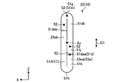
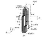
- FIG. 1 is a schematic and exemplary perspective view of a battery 10 of the present embodiment.
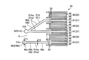
- FIG. 2 is a schematic and exemplary exploded perspective view of the battery 10 of the present embodiment.
- the battery 10 includes a housing 20, a positive electrode terminal 23, a negative electrode terminal 24, an electrode assembly 25, a positive electrode lead 26, and a negative electrode lead 27.
- the battery 10 is, for example, a lithium ion secondary battery.
- the positive electrode terminal 23 and the negative electrode terminal 24 are exposed to the outside of the housing 20 in a state of being supported by the housing 20.
- the electrode body 25, the positive electrode lead 26, and the negative electrode lead 27 are accommodated in the housing 20.
- the positive electrode terminal 23 and the negative electrode terminal 24 are examples of terminals.
- the positive electrode terminal 23 and the negative electrode terminal 24 are also referred to as electrode terminals.
- the housing 20 is configured in a flat rectangular shape that is thin in the X direction.
- the housing 20 has a plurality of wall portions 20a to 20f.
- Each of the wall portion 20a and the wall portion 20c extends along a direction intersecting with the thickness direction (X direction) of the housing 20 (in the present embodiment, for example, a direction orthogonal to the YZ plane).
- the wall 20 a and the wall 20 c are provided in parallel with each other at an interval in the thickness direction (X direction) of the housing 20.
- the wall portion 20b and the wall portion 20d both extend along a direction (for example, a direction orthogonal to the XZ plane in the present embodiment) intersecting with the width direction (Y direction) of the housing 20.
- the wall 20 b and the wall 20 d are provided in parallel with each other at an interval in the width direction (Y direction) of the housing 20.
- the walls 20a to 20d are also referred to as side walls or the like.
- the wall portions 20a and 20c are examples of the long side portion of the side wall portion, and the wall portions 20b and 20d are examples of the short side portion of the side wall portion.
- the wall 20 e and the wall 20 f both extend along a direction (for example, a direction orthogonal to the present embodiment, an XY plane) intersecting with the vertical direction (Z direction) of the housing 20.
- the wall 20 e and the wall 20 f are provided in parallel with each other at an interval in the vertical direction (Z direction) of the housing 20.
- the wall 20 e is also referred to as a lower wall, a bottom wall, or the like.
- the wall portion 20 f is also referred to as an upper wall portion, a ceiling wall portion, or the like.
- the housing 20 is also referred to as an outer can or a case.
- the housing 20 can be comprised combining a some components (divided body).
- the housing 20 includes the housing member 21 including at least the wall portions 20a to 20e, and the lid member 22 including at least the wall portion 20f.
- the accommodation member 21 is configured in a rectangular parallelepiped box shape whose one end side (upper end side) is open.
- the lid member 22 is formed in a rectangular (rectangular) plate shape, and is coupled (integrated) with the housing member 21 in a state where the opening of the housing member 21 is closed.
- the housing member 21 and the lid member 22 can be airtightly and fluidically coupled, for example, by welding or the like.
- the housing member 21 and the lid member 22 are made of, for example, a metal material (for example, aluminum, aluminum alloy, stainless steel, etc.).
- An insulating member may be provided on the inner surface of the wall portions 20a to 20e to insulate the housing member 21 from the container such as the positive electrode lead 26 and the negative electrode lead 27.
- the insulating member may be made of, for example, an insulating sheet or a molded product.
- the housing member 21 and the lid member 22 are also referred to as a housing member.
- the positive electrode terminal 23, the negative electrode terminal 24, the electrode assembly 25, the positive electrode lead 26, and the negative electrode lead 27 are attached to the lid member 22.
- the lid member 22 constitutes the lid assembly 11 together with the positive electrode terminal 23, the negative electrode terminal 24, the electrode body 25, the positive electrode lead 26, and the negative electrode lead 27.
- the positive electrode terminal 23 and the negative electrode terminal 24 are provided on the lid member 22 (wall 20f). Specifically, the positive electrode terminal 23 is provided at one end of the lid member 22 in the longitudinal direction (Y direction, width direction of the housing 20), and the negative electrode terminal 24 is disposed in the longitudinal direction (Y direction, housing of the lid member 22). It is provided at the other end of the body 20 in the width direction).
- the positive electrode terminal 23 is supported by the wall 20 f (the housing 20) in a state of penetrating the wall 20 f and is coupled to the positive electrode lead 26 inside the housing 20. That is, the positive electrode terminal 23 is electrically connected to the positive electrode lead 26.
- the negative electrode terminal 24 is supported by the wall 20 f (the housing 20) in a state of penetrating the wall 20 f and is coupled to the negative electrode lead 27 inside the wall 20 f (the housing 20). That is, the negative electrode terminal 24 is electrically connected to the negative electrode lead 27.
- seal members 28 are provided between the positive electrode terminal 23 and the wall portion 20 f and between the negative electrode terminal 24 and the wall portion 20 f, respectively.
- the seal member 28 is made of an insulator such as a synthetic resin material or glass.
- the seal member 28 seals (seals) air tight and liquid tight and electrically insulates between the positive electrode terminal 23 and the negative electrode terminal 24 and the wall portion 20 f.
- a liquid injection port (not shown) is provided in the wall portion 20 f between the positive electrode terminal 23 and the negative electrode terminal 24. An electrolyte is injected into the housing 20 from the injection port. The filling port is closed after filling.
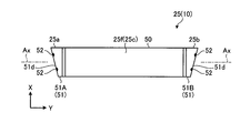
- FIG. 3 is a schematic and exemplary exploded perspective view of the electrode body 25 of the battery 10 of the present embodiment, showing a state in which a part of the electrode body 25 is developed.
- the electrode body 25 has a sheet-like positive electrode 31, a sheet-like negative electrode 32, and a plurality of sheet-like separators 33.
- the electrode body 25 functions as a power generation element.
- the separators 33 are hatched for understanding.
- the positive electrode 31 and the negative electrode 32 are examples of a pair of electrodes having different polarities.
- the electrode body 25 is also referred to as an electrode group or a wound body.
- the electrode body 25 has a flat outer appearance in which the positive electrode 31 and the negative electrode 32 and the separator 33 interposed between the positive electrode 31 and the negative electrode 32 are stacked and wound on each other. That is, the positive electrode 31 and the negative electrode 32 are overlapped via the separator 33.
- the number of windings of the positive electrode 31, the negative electrode 32, and the separator 33 is 38, for example.
- the number of windings of the positive electrode 31, the negative electrode 32, and the separator 33 may be other than 38 times.
- the positive electrode 31 and the negative electrode 32 are separated by the separator 33.
- the positive electrode 31 is located between the two separators 33.
- the positive electrode 31, the negative electrode 32, and the separator 33 are spirally wound around the central axis Ax in a state of being stacked on one another, and pressed flatly, whereby the electrode body 25 is manufactured.
- the electrode body 25 is accommodated in the housing 20 in a posture in which the central axis Ax is along the width direction (Y direction) of the housing 20.
- the central axis Ax is also referred to as a center line or a winding center line.
- the electrode assembly 25 has both axial end portions 25a and 25b, and both end portions 25c and 25d of the first direction D1 intersecting (orthogonal to) the axial direction.
- the first direction D1 is along the vertical direction (Z direction) of the housing 20.
- the end 25 c is an end on one side (upper side) of the first direction D 1 of the electrode body 25, and the end 25 d is an end on the other side (lower side) of the first direction D 1 of the electrode body 25.
- the electrode body 25 has a base portion 25e and a pair of folded portions 25f and 25g.
- the base portion 25 e and the pair of folded portions 25 f and 25 g respectively include a positive electrode 31, a negative electrode 32, and a separator 33.
- the base 25e has a pair of extending portions 25ea and 25eb in which the positive electrode 31, the negative electrode 32, and the separator 33 extend in the first direction D1.
- the extension portions 25ea and 25eb are provided between both end portions 25c and 25d of the electrode body 25 in the first direction D1. Further, a central axis Ax is located between the extensions 25ea and 25eb.
- the positive electrode 31, the negative electrode 32, and the separator 33 extend in the first direction D1, and the positive electrode 31, the negative electrode 32, and the separator 33 are not folded back.
- the base portion 25e is also referred to as a straight portion or an intermediate portion, and the folded portions 25f and 25g are also referred to as an R portion.
- the pair of folded portions 25f, 25g are provided at both end portions 25c, 25d of the electrode body 25 in the first direction D1.
- the positive electrode 31, the negative electrode 32, and the separator 33 are folded back from one of the pair of extended portions 25ea and 25eb to the other. That is, the pair of folded back portions 25f, 25g is connected to both ends of the base portion 25e in the first direction D1.
- the pair of folded back portions 25f, 25g are connected by the base portion 25e. That is, the base portion 25e is interposed between the pair of folded portions 25f and 25g.
- the positive electrode 31 has a positive electrode current collector 41 and a positive electrode active material containing layer 42.
- the positive electrode active material-containing layer 42 is hatched for the sake of understanding.
- the positive electrode current collector 41 is an example of a current collector, and the positive electrode active material containing layer 42 is an example of an active material containing layer.
- the positive electrode current collector 41 is also referred to as a substrate, a sheet, or a conductor.
- the positive electrode current collector 41 is made of a metal foil such as an aluminum foil or an aluminum alloy. That is, the positive electrode current collector 41 contains aluminum.
- the positive electrode current collector 41 is formed in a substantially rectangular (square) sheet shape (stripe).
- the positive electrode current collector 41 may be made of another material, or may be formed in another shape.
- the positive electrode active material-containing layer 42 is provided on both sides (front and back) of the positive electrode current collector 41.
- the positive electrode active material-containing layer 42 may be provided only on one side of the positive electrode current collector 41.
- the positive electrode active material containing layer 42 partially covers both surfaces of the positive electrode current collector 41. That is, the positive electrode active material containing layer 42 is laminated on part of the positive electrode current collector 41.
- the length in the longitudinal direction of the positive electrode active material-containing layer 42 is substantially equal to the length in the longitudinal direction of the positive electrode current collector 41.
- the length (width) of the positive electrode active material-containing layer 42 in the lateral direction is shorter than the length (width) of the positive electrode current collector 41 in the lateral direction.
- the positive electrode current collector 41 has a positive electrode non-laminated portion 48A.
- the positive electrode non-laminated portion 48 ⁇ / b> A is configured by a portion of the positive electrode current collector 41 where the positive electrode active material-containing layer 42 is not stacked.
- the positive electrode non-laminated portion 48A is provided at one end of the strip-shaped positive electrode current collector 41 in the width direction. The other end of the positive electrode current collector 41 in the width direction is covered with the positive electrode active material-containing layer 42.
- the positive electrode non-laminated portion 48A extends in parallel with the positive electrode current collector 41 and the positive electrode active material containing layer 42.
- the positive electrode non-laminated portion 48A is an example of the non-laminated portion.
- the positive electrode non-laminated portion 48A is also referred to as an uncoated portion.
- the positive electrode active material containing layer 42 contains a positive electrode active material, a conductive agent, and a binder (binder).
- the positive electrode active material-containing layer 42 is obtained, for example, by suspending the positive electrode active material, the conductive agent, and the binder in a solvent, and applying the suspension (slurry) to the positive electrode current collector 41, drying, and pressing. It is formed.
- the positive electrode active material is, for example, various oxides or sulfides.
- the positive electrode active material is, for example, manganese dioxide (MnO 2 ), iron oxide, copper oxide, nickel oxide, lithium manganese composite oxide (for example, Li x Mn 2 O 4 or Li x MnO 2 ), lithium nickel composite oxide ( For example, Li x NiO 2), lithium cobalt composite oxide (Li x CoO 2), lithium nickel cobalt composite oxide (e.g., Li x Ni 1-y- z Co y M z O 2 .M is, Al, Cr And at least one element selected from the group consisting of Fe, 0 ⁇ y ⁇ 0.5, 0 ⁇ z ⁇ 0.1), lithium manganese cobalt composite oxide (eg, Li x Mn 1 -y-z) Co y M z O 2 .M is, Al, Cr, and at least one element .0 ⁇ y ⁇ 0.5,0 ⁇ z ⁇ 0.1), lithium
- the positive electrode active material may be a conductive polymer material such as polyaniline or polypyrrole, a disulfide-based polymer material, sulfur (S), and an organic material or an inorganic material such as carbon fluoride.
- a conductive polymer material such as polyaniline or polypyrrole
- S sulfur
- an organic material or an inorganic material such as carbon fluoride.
- it is preferable that it is a range of 0 or more and 1 or less x, y, and z which do not have description of a preferable range above.
- More preferable positive electrode active materials are, for example, lithium manganese composite oxide, lithium nickel composite oxide, lithium cobalt composite oxide, lithium nickel cobalt composite oxide, lithium manganese nickel composite compound, spinel lithium manganese nickel composite oxide, lithium It is a manganese cobalt composite oxide or lithium iron phosphate.
- the battery 10 having these positive electrode active materials can obtain a high voltage.
- the conductive agent is, for example, one or more of acetylene black, carbon black, graphite, coke, carbon fiber, graphene and the like.
- the binder for example, polytetrafluoroethylene (PTFE), polyvinylidene fluoride (PVDF), fluorine-based rubber, styrene butadiene rubber, ethylene-butadiene rubber (SBR), polypropylene (PP), polyethylene (PE), carboxymethyl cellulose ( CMC), polyimide (PI), polyacrylimide (PAI), modified PVDF in which at least one of hydrogen and fluorine of PVDF is substituted with another substituent, copolymer of vinylidene fluoride and 6-fluoro fluoride, polyfluorophenyl Mention may be made of vinylidene fluoride-tetrafluoroethylene-6 propylene propylene terpolymer and acrylic resins.
- the type of binder can be one type or two or more types.
- the negative electrode 32 has a negative electrode current collector 45 and a negative electrode active material containing layer 46.
- the negative electrode active material containing layer 46 is hatched for the sake of understanding.
- the negative electrode current collector 45 is an example of a current collector, and the negative electrode active material containing layer 46 is an example of an active material containing layer.
- the negative electrode current collector 45 is also referred to as a substrate, a sheet, or a conductor.
- the negative electrode current collector 45 is made of, for example, a metal foil such as copper foil, aluminum foil, or aluminum alloy foil. That is, when the negative electrode current collector 45 is made of aluminum foil or aluminum alloy foil, it contains aluminum.
- the negative electrode current collector 45 is formed in a substantially rectangular (square) sheet shape (stripe).
- the negative electrode current collector 45 may be made of another material, or may be formed in another shape.
- the negative electrode active material containing layer 46 is provided on both sides of the negative electrode current collector 45. That is, the negative electrode active material containing layer 46 is laminated on part of the negative electrode current collector 45.
- the negative electrode active material containing layer 46 may be provided only on one side of the negative electrode current collector 45. However, the negative electrode active material containing layer 46 is provided on the surface facing the positive electrode active material containing layer 42.
- the negative electrode active material containing layer 46 partially covers the surface of the negative electrode current collector 45. That is, the negative electrode active material containing layer 46 is laminated on part of the negative electrode current collector 45.
- the length in the longitudinal direction of the negative electrode active material-containing layer 46 is substantially equal to the length in the longitudinal direction of the negative electrode current collector 45.
- the length (width) in the short direction of the negative electrode active material-containing layer 46 is shorter than the length (width) in the short direction of the negative electrode current collector 45.
- the negative electrode current collector 45 has a negative electrode non-laminated portion 48B.
- the negative electrode non-laminated portion 48 B is configured by a portion of the negative electrode current collector 45 where the negative electrode active material containing layer 46 is not stacked.
- the negative electrode non-laminated portion 48 B is provided at one end in the width direction of the strip-shaped negative electrode current collector 45. The other end of the negative electrode current collector 45 in the width direction is covered with the negative electrode active material containing layer 46.
- the negative electrode non-laminated portion 48 B extends in parallel to the negative electrode current collector 45 and the negative electrode active material containing layer 46.
- the negative electrode non-laminated portion 48B is an example of the non-laminated portion.
- the negative electrode non-laminated portion 48B is also referred to as an uncoated portion.
- the negative electrode active material containing layer 46 contains a negative electrode active material, a conductive agent, and a binder (binder).
- the negative electrode active material-containing layer 46 is made by suspending a powdery negative electrode active material, a conductive agent, and a binder in a solvent, and applying the suspension (slurry) to the negative electrode current collector 45, drying, and pressing It is formed by doing. A press is performed to increase the electrical contact between the negative electrode active material and the negative electrode current collector 45.
- the negative electrode active material is not particularly limited.
- the negative electrode active material is, for example, lithium titanium composite oxide (lithium titanate).
- the lithium titanium composite oxide is, for example, a spinel type lithium titanate represented by Li 4 + x Ti 5 O 12 (x changes in a range of ⁇ 1 ⁇ x ⁇ 3 by charge and discharge reaction), a ramsteride type Li 2 + x Ti.
- this metal complex oxide has a low crystallinity and a microstructure in which a crystalline phase and an amorphous phase coexist or exist alone in the amorphous phase.
- a microstructure metal complex oxide can significantly improve the cycle performance.
- These metal complex oxides are converted to lithium titanium complex oxides by the insertion of lithium upon charging.
- spinel-type lithium titanate is preferable because it has excellent cycle characteristics.
- the lithium-titanium composite oxide eg, spinel type lithium titanate
- the negative electrode active material containing layer 46 may contain, for example, a graphitic material, a carbonaceous material or a metal compound as another negative electrode active material.
- the graphite material is, for example, graphite (natural graphite, artificial graphite).
- the carbonaceous material is, for example, coke, carbon fiber (vapor-grown carbon fiber, mesophase pitch-based carbon fiber), spherical carbon, pyrolytic gas-phase carbonaceous material, or resin-fired carbon. More preferred carbonaceous materials are vapor grown carbon fibers, mesophase pitch based carbon fibers, and spherical carbon.
- the metal compound is, for example, metal sulfide or metal nitride.
- the metal sulfide is, for example, titanium sulfide such as TiS 2 , molybdenum sulfide such as MoS 2 , or iron sulfide such as FeS, FeS 2 and Li x FeS 2 .
- Metal nitrides are, for example, lithium cobalt nitride (e.g. Li s Co t N, 0 ⁇ s ⁇ 4,0 ⁇ t ⁇ 0.5).
- the negative electrode active material may be a chalcogen compound (eg, titanium disulfide, molybdenum disulfide, niobium selenide, etc.) or a light metal (eg, aluminum, aluminum alloy, magnesium alloy, lithium, lithium alloy, etc.) .
- chalcogen compound eg, titanium disulfide, molybdenum disulfide, niobium selenide, etc.
- a light metal eg, aluminum, aluminum alloy, magnesium alloy, lithium, lithium alloy, etc.
- the conductive agent is, for example, one or more of acetylene black, carbon black, graphite, coke, carbon fiber, graphene and the like.
- the binder for example, polytetrafluoroethylene (PTFE), polyvinylidene fluoride (PVDF), fluorine-based rubber, styrene butadiene rubber, ethylene-butadiene rubber (SBR), polypropylene (PP), polyethylene (PE), carboxymethyl cellulose ( CMC), polyimide (PI), polyacrylimide (PAI), modified PVDF in which at least one of hydrogen and fluorine of PVDF is substituted with another substituent, copolymer of vinylidene fluoride and 6-fluoro fluoride, polyfluorophenyl Mention may be made of vinylidene fluoride-tetrafluoroethylene-6 propylene propylene terpolymer and acrylic resins.
- the type of binder can be one type or two or more types.
- the positive electrode non-stacked portion 48A and the negative electrode non-stacked portion 48B protrude in the opposite direction to each other. That is, the positive electrode non-laminated portion 48A protrudes from one end of the positive electrode 31, the negative electrode 32, and the separator 33 which are stacked and wound on one another in the axial direction (Y direction), and the negative electrode non-laminate from the other end.
- the stacked portion 48B protrudes on the other side in the axial direction (opposite to the Y direction). That is, the positive electrode 31 and the negative electrode 32 are mutually offset and overlapped.
- the non-laminated portion 48 may be used as a generic term for the positive electrode non-laminated portion 48A and the negative electrode non-laminated portion 48B.
- a flat power generation unit 50 is configured by the overlapping portions of the positive electrode 31, the negative electrode 32, and the separator 33 in a wound state.
- the positive electrode non-laminated portion 48A in a wound state constitutes a positive electrode current collector 51A extending from one end of the power generation unit 50. That is, the positive electrode current collecting portion 51A includes a portion (positive electrode non-laminated portion 48A) in which the positive electrode active material-containing layer 42 is not stacked in the positive electrode current collector 41.
- the positive electrode current collector 51A is configured by the positive electrode 31.
- the axial end 25a of the electrode body 25 is also an end of the positive electrode current collector 41 and the positive electrode non-laminated portion 48A.
- the positive electrode current collector 51A is electrically connected to the positive electrode terminal 23.
- the positive electrode current collector 51A is an example of a current collector.
- the negative electrode non-laminated portion 48B in a wound state forms a negative electrode current collector 51B extending from the other end of the power generation unit 50. That is, the negative electrode current collecting portion 51B includes a portion (negative electrode non-laminated portion 48B) in which the negative electrode active material containing layer 46 is not stacked in the negative electrode current collector 45. As understood from the above, the negative electrode current collector 51B is configured by the negative electrode 32. The axial end 25 b of the electrode body 25 is also an end of the negative electrode current collector 45 and the negative electrode non-laminated portion 48 B. The negative electrode current collector 51B is electrically connected to the negative electrode terminal 24.
- the current collection unit 51 may be used as a generic name of the positive electrode current collection unit 51A and the negative electrode current collection unit 51B.
- the negative electrode current collector 51B is an example of a current collector.
- FIG. 4 is a schematic and exemplary view of the current collection unit 51 of the electrode body 25 according to the present embodiment, as viewed from the axial direction.
- the positive electrode current collection unit 51 ⁇ / b> A includes a plurality of current collection tabs 51 ⁇ / b> Aa stacked one on another.
- the plurality of current collection tabs 51Aa are a part of the positive electrode non-stacked portion 48A, that is, a part of the positive electrode 31, and are stacked on each other without the negative electrode 32 and the separator 33 being other electrodes.
- the boundaries between the current collection tabs 51Aa may be provided, for example, at both ends of the positive electrode current collection unit 51A in the first direction D1.
- FIG. 1 In FIG.
- the boundary between the current collection tabs 51Aa is indicated by a solid line L1.
- the position of the boundary portion is not limited to this, and may be any position.
- the positive electrode current collection unit 51A and the negative electrode current collection unit 51B are illustrated without being distinguished for describing the same configuration included in the positive electrode current collection unit 51A and the negative electrode current collection unit 51B.
- the negative electrode current collection unit 51B includes a plurality of current collection tabs 51Ba stacked on one another.
- the current collection tab 51Ba is a part of the negative electrode non-laminated portion 48B, that is, a part of the negative electrode 32, and is stacked on each other without the positive electrode 31 and the separator 33 which are other electrodes.
- boundary portions between the current collection tabs 51Ba may be provided, for example, at both ends of the negative electrode current collection unit 51B in the first direction D1.
- the boundary between the current collection tabs 51 ⁇ / b> Ba is indicated by a solid line L ⁇ b> 2.
- the position of the boundary portion is not limited to this, and may be any position.
- the current collection tab 51a may be used as a generic term for the current collection tab 51Aa of the positive electrode current collection unit 51A and the current collection tab 51Ba of the negative electrode current collection unit 51B.
- the edge 51 b of the current collection tab 51 a is provided at the end 25 a or 25 b opposite to the power generation unit 50 of the current collection unit 51 and exposed. ing.
- the plurality of current collection tabs 51 a stacked on each other in each current collection unit 51 have their respective edge portions 51 b aligned.
- the positions of the edge portions 51b of the plurality of current collection tabs 51a overlapped with each other are aligned in the axial direction. That is, the edge portions 51b of the plurality of current collection tabs 51a overlapped with each other are located at the same position in the axial direction.
- the edges 51 b of the plurality of current collection tabs 51 a stacked on one another are located on a predetermined plane that intersects (orthogonal) with the axial direction.
- Each current collection unit 51 is provided with a cutting unit 51 d.
- the cutting portion 51 d is provided at both end portions 51 g and 51 h of the current collecting portion 51 in the first direction D1 at the end portions 25 a and 25 b opposite to the power generation portion 50 of the current collecting portion 51.
- the cutting unit 51 d includes an edge 51 b of the current collection tab 51 a. That is, the cutting unit 51d constitutes the end 25a, 25b of the current collecting unit 51 opposite to the power generation unit 50 and the edge 51b of the current collecting tab 51a.
- the cutting portion 51 d is formed by melting and cutting off the removing portion 60 c (FIG. 8) from the current collecting portion 51 in the base 60 (FIG. 8) of the electrode body 25 at the time of manufacturing the electrode body 25. is there.
- the cutting portion 51 d is also referred to as a cutting portion or a cutting surface.
- FIG. 5 is a schematic and exemplary cross-sectional view of a portion of the electrode body 25 of the present embodiment.
- each current collection unit 51 is provided with a junction 52.
- the gap S between two adjacent current collection tabs 51a is exaggerated for the sake of understanding.
- the joint portion 52 joins the edge portions 51 b of the plurality of current collection tabs 51 a stacked on each other in the current collection unit 51.
- the bonding portion 52 is formed by solidification of the edge portion 51b after melting when the removal portion 60c (FIG. 8) is fused to the current collecting portion 51 in the base material 60 (FIG. 8). .
- the joint portion 52 is provided in the cutting portion 51d, and constitutes the edge portion 51b.
- the bonding portion 52 partially bonds the edges 51 b of the plurality of current collecting tabs 51 a stacked on one another.
- the plurality of bonding portions 52 are provided separately from one another. That is, in each current collection unit 51, a plurality of junctions 52 are provided in a distributed manner.
- the number and positions of the joint portions 52 shown in FIGS. 2, 4 and 5 are merely examples, and the present invention is not limited thereto. Further, the joint 52 may be one.
- FIG. 6 is a schematic and exemplary cross-sectional view of part of the current collection unit 51 of the present embodiment.
- FIG. 7 is a schematic and exemplary cross-sectional view of part of the current collection unit 51 of the present embodiment.
- each non-stacked portion 48 has a first portion 48a and a second portion 48b.
- the 1st part 48a and the 2nd part 48b of positive electrode non-laminated part 48A are shown.
- the first portion 48 a extends from the positive electrode active material containing layer 42 or the negative electrode active material containing layer 46.
- the first portion 48a constitutes a part of the current collection tab 51a.
- the second portion 48 b is connected to the first portion 48 a and constitutes the other portion of the current collection tab 51 a.
- the second portion 48b includes an edge 51b, a thickness change portion 48c, and a thick portion 48d.
- the thickness change portion 48c becomes thicker as it goes away from the first portion 48a.
- the thick portion 48 d is the portion with the largest thickness in the non-laminated portion 48 and is also the portion with the largest thickness in the current collection tab 51 a.
- the thickness of the thick portion 48d is, for example, 1.2 or more times the thickness (maximum thickness) of the first portion 48a. 5 and 6, the thickness of the thick portion 48d is indicated by the thickness T1, and the thickness (maximum thickness) of the first portion 48a is indicated by the thickness T2. In the example of FIG. 6, for example, the thickness T1 of the thick portion 48d is 67 ⁇ m, and the thickness T2 of the first portion 48a is 20 ⁇ m.
- FIG. 7 shows a current collection tab 51a different from the current collection tab 51a provided in the non-stacked portion 48 shown in FIG. In the example of FIG. 7, for example, the thickness T1 of the thick portion 48d is 20 ⁇ m, and the thickness T2 of the first portion 48a is 13 ⁇ m.
- the thickness T1 of the thick portion 48d and the thickness T2 of the first portion 48a are not limited to the above examples.
- the first portion 48a is also referred to as a thin portion.
- the positive electrode current collecting portion 51A as an example, portions of the positive electrode non-laminated portions 48A overlapping each other in the X direction are overlapped with the leg portion 26a of the positive electrode lead 26 in the X direction. The parts are joined together by ultrasonic bonding or the like. Then, the width in the X direction of at least the tip of the positive electrode current collector 51A is narrower than the width in the X direction of the electrode assembly 25 (FIG. 2).
- the portions of the negative electrode non-laminated portions 48B overlapping each other in the X direction and portions overlapping the leg 27a of the negative electrode lead 27 in the X direction Are joined by
- the width in the X direction of at least the tip of the negative electrode current collector 51B is narrower than the width in the X direction of the electrode assembly 25 (FIG. 2).
- FIG. 3 portions of the positive electrode non-laminated portions 48A overlapping in the X direction and portions of the negative electrode non-laminated portion 48B overlapping in the X direction are shown before being joined to each other. It is done.
- the separator 33 shown in FIG. 3 and the like has an insulating property and is formed in a substantially rectangular (square) sheet shape (strip).
- the length (width) of the separator 33 in the short direction is shorter than the length (width) of the positive electrode current collector 41 and the negative electrode current collector 45 in the short direction.
- the dimensions of the separator 33 are not limited to this.
- the separator 33 is, for example, a porous film made of a polyolefin such as polyethylene or polypropylene, cellulose, polyethylene terephthalate, polyester, polyvinyl alcohol, polyimide, polyamide, polyamide imide, polytetrafluoroethylene, vinylon or the like, or non-woven fabric It is. Examples of preferred separators in terms of thinness and mechanical strength include nonwoven fabrics containing cellulose fibers.
- the separator 33 may be made of one type of material, or may be made of two or more types of combined materials.
- a non-aqueous electrolyte can be used as the electrolytic solution.
- the non-aqueous electrolyte may be, for example, a liquid non-aqueous electrolyte prepared by dissolving the electrolyte in an organic solvent, or a gel non-aqueous electrolyte in which a liquid electrolyte and a polymer material are complexed.
- the liquid non-aqueous electrolyte is preferably one in which the electrolyte is dissolved in an organic solvent at a concentration of 0.5 mol / L to 2.5 mol / L.
- Examples of the electrolyte to be dissolved in an organic solvent include lithium perchlorate (LiClO 4 ), lithium hexafluorophosphate (LiPF 6 ), lithium tetrafluoroborate (LiBF 4 ), lithium hexafluoride arsenic (LiAsF 6) And lithium salts such as lithium trifluoromethanesulfonate (LiCF 3 SO 3 ), and bistrifluoromethylsulfonylimide lithium (LiN (CF 3 SO 2 ) 2 ), and mixtures thereof. It is preferable that the electrolyte be resistant to oxidation even at high potential, and LiPF 6 is most preferable.
- organic solvents examples include cyclic carbonates such as propylene carbonate (PC), ethylene carbonate (EC) and vinylene carbonate and diethyl carbonate (DEC), dimethyl carbonate (DMC) and ethyl methyl carbonate (EMC).
- PC propylene carbonate
- EC ethylene carbonate
- DEC vinylene carbonate and diethyl carbonate
- DMC dimethyl carbonate
- EMC ethyl methyl carbonate
- Cyclic carbonates and cyclic ethers such as tetrahydrofuran (THF), 2-methyltetrahydrofuran (2-MeTHF), and dioxolane (DOX), and linear chains such as dimethoxyethane (DME) and diethoxyethane (DEE) Ethers, propionate esters such as methyl propionate (MP) and ethyl propionate (EP), ⁇ -butyrolactone (GBL), acetonitrile (AN) and sulfolane (SL) are included. These organic solvents can be used alone or as a mixed solvent.
- the positive electrode lead 26 is interposed between the positive electrode current collector portion 51A of the electrode body 25 and the positive electrode terminal 23, and the positive electrode current collector portion 51A and the positive electrode terminal 23 are electrically connected. There is.
- the positive electrode lead 26 has a pair of legs 26 a and a connection wall (not shown).
- the pair of leg portions 26 a extends in the vertical direction (Z direction) of the housing 20 and is provided at an interval from each other in the thickness direction (X direction) of the housing 20.
- the pair of leg portions 26a is joined to the positive electrode current collector 51A with the positive electrode current collector 51A interposed therebetween.
- the some laminated current collection tab 51a is mutually joined.
- the joining of the pair of leg portions 26a and the positive electrode current collecting portion 51A and the joining of the stacked plurality of current collecting tabs 51a are performed by, for example, ultrasonic bonding or the like.
- the ends on the lid member 22 (wall 20f) side of the pair of legs 26a are connected to each other by a connection wall.
- the connection wall portion is provided along the inner surface of the lid member 22 and is coupled to the positive electrode terminal 23.
- the positive electrode lead 26 is made of a conductive material such as a metal material.
- the negative electrode lead 27 is interposed between the negative electrode current collector 51B of the electrode body 25 and the negative electrode terminal 24, and electrically connects the negative electrode current collector 51B to the negative electrode terminal 24.
- the negative electrode lead 27 has a pair of legs 27 a and a connection wall (not shown).
- the pair of legs 27 a extends in the vertical direction (Z direction) of the housing 20 and is provided at an interval in the thickness direction (X direction) of the housing 20.
- the pair of leg portions 27a is joined to the negative electrode current collector 51B with the negative electrode current collector 51B interposed therebetween.
- the joining of the pair of leg portions 27a and the negative electrode current collecting portion 51B and the joining of the stacked plurality of current collecting tabs 51a are performed by, for example, ultrasonic bonding or the like.
- the ends on the lid member 22 (wall 20f) side of the pair of legs 27a are connected to each other by a connection wall.
- the connection wall portion is provided along the inner surface of the lid member 22 and is coupled to the negative electrode terminal 24.
- the negative electrode lead 27 is made of a conductive material such as a metal material.
- FIG. 8 is a schematic and exemplary perspective view of the electrode assembly 25 in the process of the present embodiment.
- FIG. 9 is a schematic and exemplary front view of the electrode assembly 25 in the process of the present embodiment.
- FIG. 10 is a schematic and exemplary plan view of the electrode assembly 25 in the process of the present embodiment.
- FIG. 11 is a schematic and exemplary side view of the electrode assembly 25 in the process of the present embodiment.
- the positive electrode 31 and the negative electrode 32, and the separator 33 interposed between the positive electrode 31 and the negative electrode 32 are stacked on one another and wound around the central axis Ax, thereby including the electrode assembly 25.
- the base material 60 is produced.
- the removal part 60c which is a predetermined part of the axial direction both ends 60a and 60b of the base material 60 is cut
- the cutting part 51d is formed by this cutting.
- the boundary line L3 between the electrode body 25 and the removing portion 60c is indicated by an alternate long and short dash line.
- the cutting of the substrate 60 is performed by cutting (melting) the heat collection portion 51 (positive electrode non-laminated portion 48A, negative electrode non-laminated portion 48B) by heat.
- the laser light from the laser irradiation device as the cutting device is applied to the current collector 51 (positive electrode non-laminated portion 48A and negative electrode non-laminated portion 48B) along the boundary L3.
- the current collector 51 (the positive electrode non-laminated portion 48A and the negative electrode non-laminated portion 48B) is heated and fused.
- the bonding portion 52 (FIGS. 2, 4 and 5) is formed in the cutting portion 51 d of the current collecting portion 51. That is, in the present embodiment, the bonding portion 52 is formed by solidifying the plurality of current collecting tabs 51 a stacked on each other in the current collecting portion 51 by laser light.
- the above laser beam may be, for example, a single mode fiber laser or a multimode fiber laser.
- the single mode fiber laser is characterized in that the diameter of the laser beam is relatively small and the energy density is high, so that the plurality of current collecting tabs 51a stacked one on another can be efficiently cut at any position.
- the diameter of the laser light that is, the cutting width becomes relatively thin, and the size of each junction 52 becomes relatively small.
- the diameter of the laser light, that is, the cutting width becomes relatively large, and the size of each bonding portion 52 becomes relatively large.
- the irradiation of the laser light may be divided and performed a plurality of times. In this case, the output of the laser irradiation apparatus per one time can be reduced. For this reason, energy loss can be made small, and the influence of the heat added to the cutting part 51d can be made small.
- the cutting of the substrate 60 is not limited to the cutting by laser light.
- the cutting of the substrate 60 may be performed by ultrasonic cutting or the like.
- the cutting device may have a pressing device capable of pressing the end portions 60 a and 60 b of the base material 60 including the current collecting portion 51 of the electrode body 25.
- the distance between the current collection tabs 51a is reduced and the gap between the current collection tabs 51a is reduced, so that the laser light is easily focused.
- the current collecting tabs 51a are easily melted.
- the tact time of cutting is likely to be shortened.
- the positive electrode current collecting portion 51A and the negative electrode current collecting portion 51B and the positive electrode lead 26 and the negative electrode lead 27 coupled to the lid member 22 are joined by ultrasonic bonding.
- the positive electrode current collection part 51A and the negative electrode current collection part 51B are pinched by the horn and the anvil of an ultrasonic bonding machine with the positive electrode lead 26 and the negative electrode lead 27, and thickness becomes thin partially.
- the positive electrode lead 26, the negative electrode lead 27, and the electrode body 25 in a state of being integrated with the lid member 22 are inserted into the housing member 21.
- the lid member 22 is coupled to the housing member 21 in a state in which the opening (upper end opening) of the housing member 21 is closed.
- an electrolytic solution is injected into the housing 20 by a predetermined amount through the liquid inlet of the lid member 22.
- the predetermined amount is, for example, an amount by which the electrode body 25 in the housing 20 is sufficiently immersed in the electrolytic solution.
- the liquid injection port is sealed.
- a polishing process is performed to polish the surface (outer surface) of the non-laminated portion 48 including the edge 51 b (cut portion 51 d).
- the processed layer on the surface is removed by a chemical polishing method such as ion milling.
- the surface of the non-laminated portion 48 is mechanically polished, the surface may be subjected to a chemical treatment with an aqueous solution of sodium hydroxide or the like.
- a scanning electron microscope is used, and imaging of the non-laminated portion 48 is performed at an observation magnification of 500 times or the like. And the thickness of each part of the non-laminated part 48 is measured from an imaging result.
- the observation magnification is not limited to the above.
- the edge portions 51 b of the plurality of current collection tabs 51 a stacked on each other in the current collection unit 51 of the electrode body 25 are joined by the joining unit 52.
- the plurality of current collection tabs 51 a stacked on each other in the current collection unit 51 are unlikely to be shifted. Therefore, deformation of the current collector 51 and hence the electrode body 25 is easily suppressed. Therefore, the strength and rigidity of the current collector 51 and the electrode body 25 can be increased compared to a configuration in which the edge 51 b of the current collector tab 51 a of the current collector 51 is not joined. Vibration resistance of the electrode body 25 is improved.
- the bonding portion 52 partially bonds the edges 51 b of the plurality of current collection tabs 51 a stacked on each other in the current collection unit 51.
- the gas generated between the positive electrode active material containing layer 42 and the negative electrode active material containing layer 46 in the electrode body 25 is joined to each other at the plurality of current collecting tabs 51Aa stacked one on another. It can discharge
- a thick portion 48 d which is the thickest portion of the non-laminated portion 48 is provided at the edge 51 b of the current collection tab 51 a of the current collection portion 51. According to such a configuration, since the thick portion 48d has a relatively high strength, the strength of the edge 51b can be increased. Thus, the vibration resistance of the current collector 51 and the electrode body 25 is improved.
- the battery 10 of the second to sixteenth embodiments has the same configuration as the battery 10 of the first embodiment. Therefore, the second to sixteenth embodiments can also achieve the same effects based on the same configuration as the first embodiment.
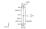
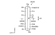
- FIG. 12 is a schematic and exemplary plan view of the electrode body 25 of the battery 10 of the present embodiment. As shown in FIG. 12, the present embodiment mainly differs from the first embodiment in the shape of the current collector 51.
- the cut portions 51 d of the end portions 25 a and 25 b of the current collection portion 51 are formed in a concave shape recessed toward the axial center of the electrode body 25.
- the cutting portion 51 d is configured in, for example, a substantially V shape when viewed from the Z direction.
- a recess 51j facing the cutting portion 51d is formed by the cutting portion 51d.
- the recess 51 j is recessed toward the axial center of the electrode body 25 (current collecting portion 51) and is formed in a groove shape extending across the both ends 25 c and 25 d of the electrode body 25.
- the recess 51 j is also referred to as a notch, a recess, a groove, or a missing portion.
- a bonding portion 52 is provided as in the first embodiment.
- the joint portion 52 faces the recess 51 j.
- the recessed portion 51 j is provided in the current collection unit 51, and the bonding portion 52 is provided in the cutting portion 51 d and faces the recessed portion 51 j. According to such a configuration, since the strength of the cut portion 51d is improved by the joint portion 52, deformation of the cut portion 51d is suppressed even when stress concentration occurs in the cut portion 51d by the recess 51j.
- FIG. 13 is a schematic and exemplary plan view of the electrode body 25 of the battery 10 of the present embodiment. As shown in FIG. 13, in the present embodiment, the shape of the current collector 51 is mainly different from that of the first embodiment.
- the cutting portion 51d of the end portions 25a and 25b of the current collecting portion 51 is inclined with respect to the central axis Ax.
- the cutting part 51d is separated from the axial center of the electrode assembly 25 as it goes from the wall 20a (FIG. 2) to the wall 20c (FIG. 2) of the housing 20, that is, as it goes to the X direction.
- a bonding portion 52 is provided as in the first embodiment.
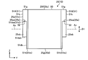
- FIG. 14 is a schematic and exemplary front view of the electrode body 25 of the battery 10 of the present embodiment.
- FIG. 15 is a schematic and exemplary side view of the electrode body 25 of the battery 10 of the present embodiment.
- the shape of the current collector 51 is mainly different from that of the first embodiment.
- one cutting part 51d is provided over the end 25a in the axial direction of the positive electrode current collector 51A and the one end 51g of the positive electrode current collector 51A in the first direction D1. Further, one cutting portion 51d is provided across the end 25a of the positive electrode current collector 51A and the other end 51h of the positive electrode current collector 51A in the first direction D1. Further, one cutting portion 51d is provided across the end 25b in the axial direction of the negative electrode current collector 51B and the one end 51g of the negative electrode current collector 51B in the first direction D1.
- one cutting portion 51d is provided along the axial end portion 25b of the negative electrode current collector 51B and the other end 51h of the negative electrode current collector 51B in the first direction D1.
- the cutting portion 51 d is provided at least one (both as an example) of both end portions 51 g and 51 h of the current collecting portion 51 in the first direction D1.
- the cutting portion 51d is inclined with respect to the central axis Ax.
- the cutting portion 51d is a central axis Ax so as to be separated from the central axis Ax as it goes from the straight portion 51k extending in the first direction D1 at the end portions 25a, 25b toward the central portion in the axial direction of the electrode body 25. It is inclined against. Further, in the cutting portion 51d, a bonding portion 52 is provided as in the first embodiment.
- the current collection part 51 has the base part 51m and the connection part 51n.
- the base portion 51m is a portion of the current collecting portion 51 axially extending from the power generation portion 50 by a predetermined length, and a portion of the base portion 25e and a portion of the pair of folded portions 25f and 25g It contains.
- the connection portion 51 n protrudes in the axial direction from the base portion 51 m.
- the connection portion 51 n includes a part of the base portion 25 e and the straight portion 51 k.
- Cutting portions 51 d are provided on both sides of the connection portion 51 n in the first direction D1.
- connection portion 51n having such a configuration includes a part of the pair of extending parts 25ea and 25eb, specifically, a part of each of the pair of extending parts 25ea and 25eb, and a part of the pair of folded parts 25f and 25g, Specifically, it includes a part of each of the pair of folded portions 25f, 25g.
- the connection portion 51 n of the positive electrode current collection unit 51 A is joined to the positive electrode lead 26 and electrically connected to the positive electrode terminal 23 via the positive electrode lead 26.
- the connection portion 51 n of the negative electrode current collecting portion 51 B is joined to the negative electrode lead 27 and electrically connected to the negative electrode terminal 24 via the negative electrode lead 27.
- an example of the boundary between the base portion 51 m and the connection portion 51 n is indicated by an alternate long and short dash line.
- the connection portion 51 n is also referred to as a protrusion or a protrusion.
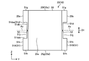
- FIG. 16 is a schematic and exemplary front view of the electrode body 25 of the battery 10 of the present embodiment.
- FIG. 17 is a schematic and exemplary side view of the electrode body 25 of the battery 10 of the present embodiment.
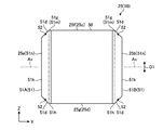
- four cutting portions 51 d are provided at each of the four corners of the electrode body 25.
- the cutting portion 51d includes a first extending portion 51da extending in the axial direction and a second extending portion 51db extending in the first direction D1.
- the connecting portion 51dc between the first extending portion 51da and the second extending portion 51db is formed in a curved shape.
- the connection portion 51dc is also referred to as a corner.
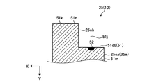
- the recessed portion 51 j facing the cutting portion 51 d is recessed toward the central portion in the axial direction of the electrode body 25 with respect to the straight portion 51 k. It can be said that the recess 51 j is recessed toward the axial center of the central axis Ax of the electrode body 25 and the center of the first direction D1. Further, a joint portion 52 is provided in the cutting portion 51 d. The joint portion 52 is provided in any one or more of the first extension portion 51da, the second extension portion 51db, and the connection portion 51dc. The joint portion 52 faces the recess 51 j.
- the current collection part 51 has the base part 51m and the connection part 51n.
- the base portion 51m is a portion of the current collecting portion 51 axially extended from the power generation portion 50 by a predetermined length, and a portion of the base portion 25e and a portion of the pair of folded portions 25f and 25g are cut.
- a second extending portion 51db of the portion 51d is configured by the exposed portion of the end portion where the connection portion 51n of the base portion 51m is provided.
- the connection portion 51 n protrudes in the axial direction from the base portion 51 m.
- the connection portion 51n includes a part of the base portion 25e, a straight portion 51k, and a first extension portion 51da of the cutting portion 51d.
- the end of the connecting portion 51 n in the first direction D1 constitutes a first extending portion 51 da.
- Cutting portions 51 d are provided on both sides of the connection portion 51 n in the first direction D1.
- the connecting portion 51n having such a configuration includes a part of the pair of extending parts 25ea and 25eb, specifically, a part of each of the pair of extending parts 25ea and 25eb, and at least the pair of folded parts 25f and 25g On the other hand, it does not specifically include both. That is, in the connection portion 51n, the positive electrode 31, the negative electrode 32, and the separator 33 are not folded back.
- an example of the boundary between the base portion 51 m and the connection portion 51 n is indicated by an alternate long and short dash line.
- FIG. 18 is a schematic and exemplary front view of the electrode body 25 of the battery 10 of the sixth embodiment.
- FIG. 19 is a schematic and exemplary side view of the electrode body 25 of the battery 10 of the sixth embodiment.
- each cutting portion 51 d is a first extension. It has a portion 51da and a second extending portion 51db.
- the connection portion 51dc between the first extending portion 51da and the second extending portion 51db is formed substantially at right angles.
- FIG. 20 is a schematic and exemplary front view of the electrode body 25 of the battery 10 of the present embodiment.
- FIG. 21 is a schematic and exemplary side view of the electrode body 25 of the battery 10 of the present embodiment.
- the shape of the current collector 51 is mainly different from that of the first embodiment.
- two cut portions 51 d are provided at two of four corners of the electrode body 25.
- one cutting part 51d is provided over the end 25a in the axial direction of the positive electrode current collector 51A and the one end 51g of the positive electrode current collector 51A in the first direction D1.
- one cutting portion 51d is provided across the end 25b in the axial direction of the negative electrode current collector 51B and the one end 51g of the negative electrode current collector 51B in the first direction D1.
- the cutting portion 51 d is provided on at least one (one as an example) of the both end portions 51 g and 51 h of the current collecting portion 51 in the first direction D1.
- the shape of each cutting portion 51d is, for example, the same as that of the sixth embodiment shown in FIG.
- the shape of each cutting portion 51d may be the shape of the fourth embodiment shown in FIG. 14 or the fifth embodiment shown in FIG.
- connection portion 51n of the current collection unit 51 of the present embodiment includes a part of each of the pair of extended portions 25ea and 25eb and a part of the folded portion 25g, and does not include the folded portion 25f.
- FIG. 22 is a schematic and exemplary front view of the electrode body 25 of the battery 10 of the present embodiment.
- FIG. 23 is a schematic and exemplary side view of the electrode body 25 of the battery 10 of the present embodiment.
- the shape of the current collector 51 is mainly different from that of the first embodiment.
- two cut portions 51 d are provided at two of four corners of the electrode body 25.
- one cutting portion 51d is provided across the end 25a of the positive electrode current collector 51A and the other end 51h of the positive electrode current collector 51A in the first direction D1.
- one cutting portion 51d is provided along the axial end portion 25b of the negative electrode current collector 51B and the other end 51h of the negative electrode current collector 51B in the first direction D1.
- the cutting portion 51 d is provided on at least one (one as an example) of the both end portions 51 g and 51 h of the current collecting portion 51 in the first direction D1.
- the shape of each cutting portion 51d is, for example, the same as that of the sixth embodiment shown in FIG.
- the shape of each cutting portion 51d may be the shape of the fourth embodiment shown in FIG. 14 or the fifth embodiment shown in FIG.
- connection portion 51n of the current collection unit 51 of the present embodiment includes a part of each of the pair of extended portions 25ea and 25eb and a part of the folded portion 25f, and does not include the folded portion 25g.
- FIG. 24 is a schematic and exemplary front view of the electrode body 25 of the battery 10 of the present embodiment.
- FIG. 25 is a schematic and exemplary side view of the electrode body 25 of the battery 10 of the present embodiment.
- FIG. 26 is a schematic and exemplary perspective view of the electrode body 25 of the battery 10 of the present embodiment.
- the shape of the current collector 51 is mainly different from that of the first embodiment.
- the current collector 51 includes a base 51 m and a connection 51 n as in the fifth embodiment.
- the connection portion 51 n of the present embodiment includes a portion of the folded portion 25 g in addition to a portion of the base portion 25 e and the straight portion 51 k.
- the lengths in the first direction D1 of the pair of extending portions 25ea, 25eb of the base portion 25e included in the connection portion 51n are different from each other.
- the length in the first direction D1 of the extending portion 25ea included in the connecting portion 51n is shorter than the length in the first direction D1 of the extending portion 25eb included in the connecting portion 51n.
- the length in the first direction D1 of the extending portion 25ea included in the connecting portion 51n may be longer than the length in the first direction D1 of the extending portion 25eb included in the connecting portion 51n.
- one cutting unit 51 d is provided for each current collecting unit 51.
- the cutting unit 51 d is provided at one end 51 g of the current collecting unit 51 in the first direction D1.
- the cutting portion 51 d includes two first extending portions 51 daa and 51 dab and one second extending portion 51 db.
- the first extending portion 51daa is configured by an end portion in one (upper) direction of the first direction D1 of one (the extending portion 25ea) of the pair of extending portions 25ea and 25eb included in the connecting portion 51n, and extends in the axial direction ing.
- the first extending portion 51dab is configured by an end portion in one side (upper side) of the first direction D1 of the other (the extending portion 25eb) of the pair of extending portions 25ea and 25eb included in the connection portion 51n.
- the second extending portion 51db is configured by an exposed portion of the end portion of the base portion 51m provided with the connecting portion 51n, and extends in the first direction D1.
- the second extending portion 51db connects the two first extending portions 51daa and 51dab.
- the recess 51 j facing the cutting portion 51 d is recessed toward the central portion in the axial direction of the electrode body 25 with respect to the straight portion 51 k. Further, a joint portion 52 is provided in the cutting portion 51 d. The joint portion 52 faces the recess 51 j.
- connection portion 51n of the current collection unit 51 of the present embodiment includes a part of each of the pair of extended portions 25ea and 25eb and a part of the folded portion 25g, and does not include the folded portion 25f.
- a shielding plate (not shown) capable of shielding laser light is located at a predetermined position of the base 60 in cutting the base 60 (FIG. 8) by the laser irradiation device. It is done in the inserted state.
- the number of cut sheets by laser light can be adjusted by such a shielding plate.
- the shielding plate can be made of, for example, a metal material.
- the metal material may be, for example, tungsten. Tungsten is a material with the highest melting point among metal materials, so that high output of laser light can be achieved.
- a shielding board can be used also by embodiment other than this embodiment.
- FIG. 27 is a schematic and exemplary front view of the electrode body 25 of the battery 10 of the present embodiment.
- FIG. 28 is a schematic and exemplary side view of the electrode body 25 of the battery 10 of the present embodiment.
- the current collection unit 51 has a base unit 51m and a connection unit 51n, and the cutting unit 51d is a collector.
- the power unit 51 is provided one by one.
- the current collection unit 51 of the present embodiment is formed in plane symmetry with respect to the XY plane passing through the center of the first direction D1 of the current collection unit 51 of the ninth embodiment and the electrode body 25 (current collection unit 51) There is.
- the connection portion 51n of the present embodiment includes a portion of the folded portion 25f in addition to a portion of the base portion 25e and the straight portion 51k.
- the length in the first direction D1 of the extending portion 25ea included in the connecting portion 51n is shorter than the length in the first direction D1 of the extending portion 25eb included in the connecting portion 51n.
- the length in the first direction D1 of the extending portion 25eb included in the connecting portion 51n may be longer than the length in the first direction D1 of the extending portion 25ea included in the connecting portion 51n.
- the cutting unit 51 d is provided at the other end 51 h of the current collecting unit 51 in the first direction D 1.
- the cutting portion 51 d includes two first extending portions 51 daa and 51 dab and one second extending portion 51 db.
- the first extending portion 51daa is configured by the other (lower) end of the first direction D1 of one of the extending portions 25ea and 25eb included in the connecting portion 51n (the extending portion 25ea), and extends in the axial direction ing.
- the first extending portion 51dab is configured by the other (lower) end portion of the first direction D1 of the other (the extending portion 25eb) of the pair of extending portions 25ea and 25eb included in the connecting portion 51n, and the axial direction It extends to
- the second extending portion 51db is configured by an exposed portion of the end portion of the base portion 51m provided with the connecting portion 51n, and extends in the first direction D1.
- the second extending portion 51db connects the two first extending portions 51daa and 51dab.
- the recess 51 j facing the cutting portion 51 d is recessed toward the central portion in the axial direction of the electrode body 25 with respect to the straight portion 51 k. Further, a joint portion 52 is provided in the cutting portion 51 d. The joint portion 52 faces the recess 51 j.
- connection portion 51n of the current collection unit 51 of the present embodiment includes a part of each of the pair of extended portions 25ea and 25eb and a part of the folded portion 25f, and does not include the folded portion 25g.
- FIG. 29 is a schematic and exemplary front view of the electrode body 25 of the battery 10 of the present embodiment.
- FIG. 30 is a schematic and exemplary side view of the electrode body 25 of the battery 10 of the present embodiment.
- the shape of the current collector 51 is mainly different from that of the first embodiment.
- one cutting portion 51 d is provided at an intermediate portion in each of the current collecting portions 51 in the first direction D1 and extends from the straight portion 51 k to the axial center of the electrode body 25. It is configured to be concave.
- the cutting portion 51 d includes two first extending portions 51 daa and 51 dab and one second extending portion 51 db.
- the two first extending portions 51daa, 51dab are spaced from each other in the first direction D1, and extend in the axial direction from the straight portion 51k toward the axial center of the electrode assembly 25.
- the two first extending portions 51daa, 51dab are provided across the two extending portions 25ea, 25eb of the base portion 25e, respectively.
- the second extending portion 51db extends in the first direction D1 and connects the ends of the two first extending portions 51daa and 51dab opposite to the straight portions 51k.
- the recessed portion 51j facing the cutting portion 51d is recessed toward the central portion side in the axial direction of the electrode body 25 with respect to the straight portion 51k, and the current collecting portion in the thickness direction (X direction) of the electrode body 25. It penetrates 51. Further, a joint portion 52 is provided in the cutting portion 51 d. The joint portion 52 faces the recess 51 j.
- FIG. 31 is a schematic and exemplary front view of the electrode body 25 of the battery 10 of the present embodiment.
- one cutting portion 51d is provided in the middle portion of each current collecting portion 51 in the first direction D1, and the straight portion 51k is provided. From the center to the center of the electrode body 25 in the axial direction.
- the cutting part 51d has two first extending parts 51daa, 51dab and one second extending part 51db.
- the axial length of the two first extending portions 51daa is longer than that in the eleventh embodiment. That is, the depth of the recess 51j is deep.
- FIG. 32 is a schematic and exemplary front view of the electrode body 25 of the battery 10 of the present embodiment.
- FIG. 33 is a schematic and exemplary side view of the electrode body 25 of the battery 10 of the present embodiment.
- FIG. 34 schematically shows a cross section taken along the line XXXIV-XXXIV of FIG. As shown in FIGS. 32 to 34, the present embodiment mainly differs in the shape of the current collector 51 from the first embodiment.
- one cutting portion 51 d is provided at an intermediate portion in each of the current collecting portions 51 in the first direction D1 and extends from the straight portion 51 k to the axial center of the electrode body 25. It is configured to be concave.
- the cutting portion 51 d includes two first extending portions 51 daa and 51 dab and one second extending portion 51 db.
- the two first extending portions 51daa, 51dab are spaced from each other in the first direction D1, and extend in the axial direction from the straight portion 51k toward the axial center of the electrode assembly 25.
- the two first extending portions 51daa, 51dab are provided only in one of the two extending portions 25ea, 25eb of the base portion 25e (the extending portion 25ea).
- the second extending portion 51db extends in the first direction D1 and connects the ends of the two first extending portions 51daa and 51dab opposite to the straight portions 51k.
- the recessed portion 51j facing the cutting portion 51d is recessed toward the central portion in the axial direction of the electrode body 25 with respect to the straight portion 51k, and the extending portion 25ea in the thickness direction (X direction) of the electrode body 25. Through.
- the recess 51 j faces the extension 25 eb in the axial direction.
- a joint portion 52 is provided in the cutting portion 51 d. The joint portion 52 faces the recess 51 j.
- FIG. 35 is a schematic and exemplary front view of the electrode body 25 of the battery 10 of the present embodiment.
- FIG. 36 is a schematic and exemplary side view of the electrode body 25 of the battery 10 of the present embodiment.
- FIG. 37 schematically shows a cross section taken along line XXXVII-XXXVII of FIG. As shown in FIGS. 35 to 37, the present embodiment mainly differs in the shape of the current collector 51 from the first embodiment.
- the current collector 51 includes a base 51 m and a connection 51 n as in the fifth embodiment.
- the connection portion 51 n of the present embodiment is provided in a half region (the left half region in FIG. 36) of the current collecting portion 51 in the first direction D1.
- the connecting portion 51n includes a part of one (the extending portion 25eb) of the pair of the extending portions 25ea and 25eb of the base portion 25e and the pair of curved portions 25h and 25i, and does not include the folded portions 25f and 25g.
- the curved portions 25h and 25i have a configuration in which the positive electrode 31 and the negative electrode 32 are curved along the folded portions 25f and 25g within a range of about 90 degrees from the end of the extending portion 25ea in the first direction D1. That is, in the curved portions 25h and 25i, the positive electrode 31 and the negative electrode 32 are not folded back.
- the curved portions 25h, 25i extend in the axial direction from the folded portions 25f, 25g.
- the boundary between the curved portions 25h and 25i and the extending portion 25ea is indicated by an alternate long and short dash line.
- the cutting portion 51 d includes two first extending portions 51 daa and 51 dab and one second extending portion 51 db.
- the first extending portions 51daa, 51dab are configured by the end portions of the pair of curved portions 25h, 25i included in the connecting portion 51n facing the first direction D1 (the opposite direction to the X direction), and extend in the axial direction .
- the second extending portion 51db is configured by an exposed portion of the end portion of the base portion 51m provided with the connection portion 51n, and extends in the first direction D1. That is, the second extending portion 51db includes the extending portion 25ea of the base portion 25e and the folded portions 25f and 25g.
- the second extending portion 51db connects the two first extending portions 51daa and 51dab.
- the recess 51 j facing the cutting portion 51 d is recessed toward the central portion in the axial direction of the electrode body 25 with respect to the straight portion 51 k. Further, a joint portion 52 is provided in the cutting portion 51 d. The joint portion 52 faces the recess 51 j.
- connection portion 51n of the current collection portion 51 of the present embodiment includes a portion of the pair of the extending portions 25ea, 25eb, specifically, a portion of the extending portion 25eb, and the extending portion 25ea and the pair of folded portions 25f, Does not contain 25g.
- FIG. 38 is a schematic and exemplary front view of the electrode body 25 of the battery 10 of the present embodiment.
- FIG. 39 is a schematic and exemplary side view of the electrode body 25 of the battery 10 of the present embodiment.
- FIG. 40 schematically shows a cross section taken along the line XL-XL in FIG. As shown in FIGS. 38 to 40, the present embodiment mainly differs in the shape of the current collector 51 from the first embodiment.
- the current collector 51 includes a base 51 m and a connection 51 n as in the fifth embodiment.
- the connecting portion 51 n of the present embodiment is provided at an intermediate portion in the first direction D1 in one (the extending portion 25 ea) of the pair of the extending portions 25 ea and 25 eb included in the current collecting portion 51.
- the cutting portion 51 d includes two first extending portions 51 daa and 51 dab and one second extending portion 51 db.
- the first extending portions 51daa and 51dab are configured by end portions facing one side (Z direction) or the other (the opposite direction of the Z direction) of the connecting portion 51n in the first direction D1 and extend in the axial direction.
- the second extending portion 51db is configured by an exposed portion of the end portion of the base portion 51m provided with the connection portion 51n, and extends in the first direction D1.
- the second extending portion 51db includes a portion of the extending portions 25ea and 25eb of the base portion 25e and a portion of the folded portions 25f and 25g.
- the second extending portion 51db connects the two first extending portions 51daa and 51dab.
- the recess 51 j facing the cutting portion 51 d is recessed toward the central portion in the axial direction of the electrode body 25 with respect to the straight portion 51 k. Further, a joint portion 52 is provided in the cutting portion 51 d. The joint portion 52 faces the recess 51 j.
- connection portion 51n of the current collection portion 51 of the present embodiment includes a part of the pair of extended portions 25ea and 25eb, specifically, a part of the extended portion 25ea, and the extended portion 25eb and the pair of folded portions 25f, Does not contain 25g.
- FIG. 41 is a schematic and exemplary front view of the electrode body 25 of the battery 10 of the present embodiment.
- FIG. 42 is a schematic and exemplary side view of the electrode body 25 of the battery 10 of the present embodiment.
- the present embodiment mainly differs in the shape of the current collector 51 from the first embodiment.
- each current collection unit 51 is provided with a plurality of (two as an example) cut portions 51 dA and 51 dB having different shapes.
- the cutting portion 51dA is the same as the cutting portion 51d of the fifth embodiment shown in FIG. 16, and the cutting portion 51 dB is the same as the cutting portion 51d of the eleventh embodiment shown in FIG.
- the sizes of the cutting portion 51dA and the cutting portion 51dB may be the same as or different from the cutting portion 51d shown in FIG. 16 and the cutting portion 51d shown in FIG.
- the junction part 52 is provided in each cutting part 51 dA and 51 dB.
Abstract
実施形態の電池は、筐体と、端子と、電極体と、集電部と、接合部と、を備えている。端子は、筐体に支持されている。電極体は、筐体に収容され、互いに極性が異なるシート状の一対の電極と前記一対の電極間に位置したセパレータとが互いに重ねられた状態で中心軸回りに巻かれている。集電部は、電極体の中心軸の軸方向の端部に設けられ、電極の一部であって他の電極およびセパレータを介さずに互いに重ねられた複数の集電タブを有し、端子と電気的に接続されている。接合部は、互いに重ねられた複数の集電タブの縁部を接合している。
Description
本発明の実施形態は、電池に関する。
従来、シート状の一対の電極と一対の電極間に位置したセパレータとが互いに重ねられた状態で巻かれた電極体と、電極体に設けられ、電極の複数の部分が重ねられた集電部と、を備えた電池が知られている。
この種の電池では、耐振動性が向上した新規な構成が得られれば、好ましい。
実施形態の電池は、筐体と、端子と、電極体と、集電部と、接合部と、を備えている。前記端子は、前記筐体に支持されている。前記電極体は、前記筐体に収容され、互いに極性が異なるシート状の一対の電極と前記一対の電極間に位置したセパレータとが互いに重ねられた状態で中心軸回りに巻かれている。前記集電部は、前記電極体の前記中心軸の軸方向の端部に設けられ、前記電極の一部であって他の前記電極および前記セパレータを介さずに互いに重ねられた複数の集電タブを有し、前記端子と電気的に接続されている。前記接合部は、互いに重ねられた複数の前記集電タブの縁部を接合している。
以下、図面を参照して、実施形態について説明する。なお、以下の例示的な複数の実施形態には、同様の構成要素が含まれている。よって、以下では、同様の構成要素には共通の符号が付されるとともに、重複する説明が省略される。
また、以下の各図では、便宜上、方向が規定されている。X方向は、電池10の筐体20の短手方向(厚さ方向)に沿い、Y方向は、筐体20の長手方向(幅方向)に沿い、Z方向は、筐体20の上下方向(高さ方向)に沿っている。X方向、Y方向、およびZ方向は、互いに直交している。また、以下では、中心軸Axの軸方向を単に軸方向と称する。また、本明細書において、序数は、部材(部品)や部位等を区別するために便宜上付与されており、優先順位や順番を示すものではない。
また、以下に示される実施形態の構成(技術的特徴)、ならびに当該構成によってもたらされる作用および効果は、あくまで一例である。本発明は、以下の実施形態に開示される構成以外によっても実現可能であるとともに、基本的な構成によって得られる種々の効果のうち少なくとも一つを得ることが可能である。
<第1実施形態>
図1は、本実施形態の電池10の模式的かつ例示的な斜視図である。図2は、本実施形態の電池10の模式的かつ例示的な分解斜視図である。図1,2に示されるように、電池10は、筐体20と、正極端子23と、負極端子24と、電極体25と、正極リード26と、負極リード27と、を有している。電池10は、例えば、リチウムイオン二次電池である。正極端子23および負極端子24は、筐体20に支持された状態で筐体20の外部に露出している。また、電極体25、正極リード26、および負極リード27は、筐体20に収容されている。正極端子23および負極端子24は、端子の一例である。正極端子23および負極端子24は、電極端子とも称される。
図1は、本実施形態の電池10の模式的かつ例示的な斜視図である。図2は、本実施形態の電池10の模式的かつ例示的な分解斜視図である。図1,2に示されるように、電池10は、筐体20と、正極端子23と、負極端子24と、電極体25と、正極リード26と、負極リード27と、を有している。電池10は、例えば、リチウムイオン二次電池である。正極端子23および負極端子24は、筐体20に支持された状態で筐体20の外部に露出している。また、電極体25、正極リード26、および負極リード27は、筐体20に収容されている。正極端子23および負極端子24は、端子の一例である。正極端子23および負極端子24は、電極端子とも称される。
筐体20は、X方向に薄い扁平な直方体状に構成されている。筐体20は、複数の壁部20a~20fを有している。壁部20aおよび壁部20cは、いずれも、筐体20の厚さ方向(X方向)と交差する方向(本実施形態では、例えば直交する方向、YZ平面)に沿って延びている。壁部20aおよび壁部20cは、筐体20の厚さ方向(X方向)に間隔を空けて互いに平行に設けられている。また、壁部20bおよび壁部20dは、いずれも、筐体20の幅方向(Y方向)と交差する方向(本実施形態では、例えば直交する方向、XZ平面)に沿って延びている。壁部20bおよび壁部20dは、筐体20の幅方向(Y方向)に間隔を空けて互いに平行に設けられている。壁部20a~20dは、側壁部等とも称される。また、壁部20a,20cは、側壁部のうちの長辺部の一例であり、壁部20b,20dは、側壁部のうちの短辺部の一例である。また、壁部20eおよび壁部20fは、いずれも、筐体20の上下方向(Z方向)と交差する方向(本実施形態では、例えば直交する方向、XY平面)に沿って延びている。壁部20eおよび壁部20fは、筐体20の上下方向(Z方向)に間隔を空けて互いに平行に設けられている。壁部20eは、下壁部や、底壁部等とも称される。また、壁部20fは、上壁部や、天壁部等とも称される。筐体20は、外装缶やケースとも称される。
また、筐体20は、複数の部品(分割体)が組み合わせられて構成されることができる。具体的には、本実施形態では、筐体20は、少なくとも壁部20a~20eを含む収容部材21と、少なくとも壁部20fを含む蓋部材22と、を有している。収容部材21の内側には、電極体25や、正極リード26、負極リード27等を収容する開口部が設けられている。すなわち、収容部材21は、一端側(上端側)が開放された直方体状の箱型に構成されている。蓋部材22は、四角形状(長方形状)の板状に構成され、収容部材21の開口部を塞いだ状態で、収容部材21と結合(一体化)されている。また、収容部材21と蓋部材22とは、例えば溶接などによって気密および液密に結合されうる。収容部材21や蓋部材22は、例えば、金属材料(例えば、アルミニウムや、アルミニウム合金、ステンレス等)で構成されている。なお、壁部20a~20eの内面には、収容部材21と正極リード26および負極リード27等の収容物とを絶縁する絶縁部材が設けられうる。絶縁部材は、例えば、絶縁シートや成形品等によって構成されうる。収容部材21および蓋部材22は、筐体部材とも称される。
また、図2に示されるように、蓋部材22には、正極端子23、負極端子24、電極体25、正極リード26、および負極リード27が取り付けられている。蓋部材22は、正極端子23、負極端子24、電極体25、正極リード26、および負極リード27とともに、蓋組立体11を構成している。
正極端子23および負極端子24は、蓋部材22(壁部20f)に設けられている。具体的には、正極端子23は、蓋部材22の長手方向(Y方向、筐体20の幅方向)の一端部に設けられ、負極端子24は、蓋部材22の長手方向(Y方向、筐体20の幅方向)の他端部に設けられている。正極端子23は、壁部20fを貫通した状態で壁部20f(筐体20)に支持され、筐体20の内側で正極リード26と結合されている。すなわち、正極端子23は、正極リード26と電気的に接続されている。また、負極端子24は、壁部20fを貫通した状態で壁部20f(筐体20)に支持され、壁部20f(筐体20)の内側で負極リード27に結合されている。すなわち、負極端子24は、負極リード27と電気的に接続されている。
また、正極端子23と壁部20fとの間、および負極端子24と壁部20fとの間には、それぞれ、シール部材28(ガスケット、介在物)が設けられている。シール部材28は、合成樹脂材料やガラスなどの絶縁体で構成されている。シール部材28は、正極端子23および負極端子24と壁部20fとの間を気密および液密にシール(封止)するとともに電気的に絶縁している。また、壁部20fには、正極端子23と負極端子24との間に注液口(不図示)が設けられている。注液口から、筐体20内に電解液が注液される。注液口は、注液後に塞がれる。
図3は、本実施形態の電池10の電極体25の模式的かつ例示的な分解斜視図であって、電極体25の一部が展開された状態を示す図である。図3に示されるように、電極体25は、シート状の正極31と、シート状の負極32と、複数のシート状のセパレータ33と、を有している。電極体25は、発電要素として機能する。図3では、理解のために、セパレータ33にハッチングが付されている。正極31および負極32は、互いに極性が異なる一対の電極の一例である。電極体25は、電極群や捲回体とも称される。
電極体25は、正極31および負極32と、正極31および負極32間に介在したセパレータ33と、が互いに重ねられ且つ巻かれた構成であり、扁平形状の外観を呈している。すなわち、正極31と負極32とは、セパレータ33を介して重ねられている。正極31、負極32、およびセパレータ33の巻き回数は、一例として38回である。なお、正極31、負極32、およびセパレータ33の巻き回数は、38回以外であってもよい。正極31と負極32とは、セパレータ33によって互いに離間させられている。また、正極31は、二つのセパレータ33の間に位置している。正極31、負極32、およびセパレータ33が、互いに重ねられた状態で中心軸Ax回りに渦巻状に巻かれて、扁平にプレスされることによって、電極体25が作製される。電極体25は、中心軸Axが筐体20の幅方向(Y方向)に沿う姿勢で筐体20に収容されている。中心軸Axは、中心線や捲回中心線とも称される。
図2,3に示されるように、電極体25は、軸方向の両端部25a,25bと、軸方向と交差(直交)する第一方向D1の両端部25c,25dと、を有している。第一方向D1は、筐体20の上下方向(Z方向)に沿っている。端部25cは、電極体25の第一方向D1の一方側(上方)の端部であり、端部25dは、電極体25の第一方向D1の他方側(下方)の端部である。
また、電極体25は、基体部25eと、一対の折返部25f,25gと、を有している。基体部25eおよび一対の折返部25f,25gは、それぞれ正極31、負極32、およびセパレータ33を含む。基体部25eは、第一方向D1に正極31、負極32およびセパレータ33が延びた一対の延部25ea,25ebを有している。各延部25ea,25ebは、電極体25の第一方向D1の両端部25c,25d間に設けられている。また、延部25ea,25ebの間に中心軸Axが位置している。各延部25ea,25ebでは、正極31、負極32、およびセパレータ33が第一方向D1に延びており、正極31、負極32、およびセパレータ33は、折り返されていない。基体部25eは、直状部や中間部とも称され、折返部25f,25gは、R部とも称される。
一対の折返部25f,25gは、電極体25の第一方向D1の両端部25c,25dに設けられている。各折返部25f,25gでは、一対の延部25ea,25ebの一方から他方に、正極31、負極32、およびセパレータ33が折り返されている。すなわち、一対の折返部25f,25gは、基体部25eの第一方向D1の両端部に接続されている。一対の折返部25f,25gは、基体部25eによって接続されている。すなわち、一対の折返部25f,25gの間に基体部25eが介在している。
図3に示されるように、正極31は、正極集電体41と、正極活物質含有層42と、を有している。図3では、理解のために、正極活物質含有層42にハッチングが付されている。正極集電体41は、集電体の一例であり、正極活物質含有層42は、活物質含有層の一例である。正極集電体41は、基板やシート、導電体とも称される。
正極集電体41は、アルミニウム箔やアルミニウム合金等の金属箔によって構成されている。すなわち、正極集電体41は、アルミニウムを含む。正極集電体41は、略矩形(四角形)のシート状(帯状)に形成されている。なお、正極集電体41は、他の材料によって作られてもよく、他の形状に形成されてもよい。
正極活物質含有層42は、正極集電体41の両面(表面および裏面)に、それぞれ設けられている。なお、正極活物質含有層42は、正極集電体41の一方の面にのみ設けられてもよい。正極活物質含有層42は、正極集電体41の両面を部分的に覆っている。すなわち、正極活物質含有層42は、正極集電体41の一部に積層されている。正極活物質含有層42の長手方向の長さは、正極集電体41の長手方向の長さにほぼ等しい。正極活物質含有層42の短手方向の長さ(幅)は、正極集電体41の短手方向の長さ(幅)よりも短い。
正極集電体41は、正極非積層部48Aを有している。正極非積層部48Aは、正極集電体41のうち正極活物質含有層42が積層されていない部分によって構成されている。正極非積層部48Aは、帯状の正極集電体41の、幅方向における一方の端部に設けられている。正極集電体41の、幅方向における他方の端部は、正極活物質含有層42に覆われている。正極非積層部48Aは、正極集電体41および正極活物質含有層42と平行に延びている。正極非積層部48Aは、非積層部の一例である。正極非積層部48Aは、未塗工部とも称される。
正極活物質含有層42は、正極活物質と、導電剤と、バインダー(結着剤)とを含む。正極活物質含有層42は、例えば、正極活物質、導電剤、およびバインダーを溶媒に懸濁させ、この懸濁物(スラリー)を正極集電体41に塗工、乾燥、およびプレスすることにより形成される。
正極活物質は、例えば、種々の酸化物または硫化物である。正極活物質は、例えば、二酸化マンガン(MnO2)、酸化鉄、酸化銅、酸化ニッケル、リチウムマンガン複合酸化物(例えば、LixMn2O4またはLixMnO2)、リチウムニッケル複合酸化物(例えば、LixNiO2)、リチウムコバルト複合酸化物(LixCoO2)、リチウムニッケルコバルト複合酸化物(例えば、LixNi1-y-zCoyMzO2。Mは、Al、Cr、およびFeよりなる群から選択される少なくとも1種類の元素。0≦y≦0.5、0≦z≦0.1)、リチウムマンガンコバルト複合酸化物(例えば、LixMn1-y-zCoyMzO2。Mは、Al、Cr、およびFeよりなる群から選択される少なくとも1種類の元素。0≦y≦0.5、0≦z≦0.1)、リチウムマンガンニッケル複合化合物(例えば、LixMn1/3Ni1/3Co1/3O2やLixMn1/2Ni1/2O2のようなLixMnyNiyM1-2yO2。Mは、Co、Cr、Al、およびFeよりなる群より選択される少なくとも1種類の元素。1/3≦y≦1/2)、スピネル型リチウムマンガンニッケル複合酸化物(例えば、LixMn2-yNiyO4)、オリビン構造を有するリチウムリン酸化物(例えば、LixFePO4、LixFe1-yMnyPO4、LixCoPO4)、硫酸鉄(例えば、Fe2(SO4)3)、または、バナジウム酸化物(例えば、V2O5)である。正極活物質は、ポリアニリンやポリピロールのような導電性ポリマー材料、ジスルフィド系ポリマー材料、イオウ(S)、および、フッ化カーボンのような有機材料および無機材料であってもよい。なお、上記に好ましい範囲の記載がないx、y、zは、0以上1以下の範囲であることが好ましい。
より好ましい正極活物質は、例えば、リチウムマンガン複合酸化物、リチウムニッケル複合酸化物、リチウムコバルト複合酸化物、リチウムニッケルコバルト複合酸化物、リチウムマンガンニッケル複合化合物、スピネル型リチウムマンガンニッケル複合酸化物、リチウムマンガンコバルト複合酸化物、またはリチウムリン酸鉄である。これらの正極活物質を有している電池10は、高い電圧が得られる。
導電剤は、例えば、アセチレンブラック、カーボンブラック、黒鉛、コークス、カーボンファイバー、グラフェン等のうち1種類または2種類以上である。バインダーとしては、例えば、ポリテトラフルオロエチレン(PTFE)、ポリフッ化ビニリデン(PVDF)、フッ素系ゴム、スチレンブタジエンゴム、エチレン-ブタジエンゴム(SBR)、ポリプロピレン(PP)、ポリエチレン(PE)、カルボキシメチルセルロース(CMC)、ポリイミド(PI)、ポリアクリルイミド(PAI)、PVDFの水素およびフッ素のうち少なくとも1つを他の置換基で置換した変性PVDF、フッ化ビニリデン-6フッ化プロピレンの共重合体、ポリフッ化ビニリデン-テトラフルオロエチレン-6フッ化プロピレンの3元共重合体、アクリル系樹脂を挙げることができる。バインダーの種類は、1種類または2種類以上にすることができる。
図3に示されるように、負極32は、負極集電体45と、負極活物質含有層46と、を有している。図3では、理解のために、負極活物質含有層46にハッチングが付されている。負極集電体45は、集電体の一例であり、負極活物質含有層46は、活物質含有層の一例である。負極集電体45は、基板やシート、導電体とも称される。
負極集電体45は、例えば銅箔やアルミニウム箔、アルミニウム合金箔等の金属箔によって構成されている。すなわち、負極集電体45は、アルミニウム箔やアルミニウム合金箔で構成された場合、アルミニウムを含む。負極集電体45は、略矩形(四角形)のシート状(帯状)に形成される。なお、負極集電体45は、他の材料によって作られてもよく、他の形状に形成されてもよい。
負極活物質含有層46は、負極集電体45の両面に、それぞれ設けられている。すなわち、負極活物質含有層46は、負極集電体45の一部に積層されている。なお、負極活物質含有層46は、負極集電体45の一方の面にのみ設けられてもよい。ただし、負極活物質含有層46は、正極活物質含有層42に向く面に設けられる。負極活物質含有層46は、負極集電体45の面を部分的に覆っている。すなわち、負極活物質含有層46は、負極集電体45の一部に積層されている。負極活物質含有層46の長手方向の長さは、負極集電体45の長手方向の長さにほぼ等しい。負極活物質含有層46の短手方向の長さ(幅)は、負極集電体45の短手方向の長さ(幅)よりも短い。
負極集電体45は、負極非積層部48Bを有している。負極非積層部48Bは、負極集電体45のうち負極活物質含有層46が積層されていない部分によって構成されている。負極非積層部48Bは、帯状の負極集電体45の、幅方向における一方の端部に設けられている。負極集電体45の、幅方向における他方の端部は、負極活物質含有層46に覆われている。負極非積層部48Bは、負極集電体45および負極活物質含有層46と平行に延びている。負極非積層部48Bは、非積層部の一例である。負極非積層部48Bは、未塗工部とも称される。
負極活物質含有層46は、負極活物質と、導電剤と、バインダー(結着剤)とを含む。負極活物質含有層46は、例えば、粉末状の負極活物質、導電剤、およびバインダーを溶媒に懸濁させ、この懸濁物(スラリー)を負極集電体45に塗工、乾燥、およびプレスすることにより形成される。プレスは、負極活物質と負極集電体45との電気的接触を増加させるために行なわれる。
負極活物質は、特に限定されるものではない。負極活物質は、例えば、リチウムチタン複合酸化物(チタン酸リチウム)である。リチウムチタン複合酸化物は、例えば、Li4+xTi5O12(xは充放電反応により-1≦x≦3の範囲で変化する)で表されるスピネル型チタン酸リチウム、ラムステライド型Li2+xTi3O7(xは充放電反応により-1≦x≦3の範囲で変化する)、または、TiとP、V、Sn、Cu、NiおよびFeよりなる群から選択される少なくとも1種類の元素とを含有している金属複合酸化物である。TiとP、V、Sn、Cu、NiおよびFeよりなる群から選択される少なくとも1種類の元素とを含有している金属複合酸化物としては、例えば、TiO2-P2O5、TiO2-V2O5、TiO2-P2O5-SnO2、TiO2-P2O5-MeO(MeはCu、NiおよびFeよりなる群から選択される少なくとも1つの元素)、TiO2-P2O5-MO(MはCu、NiおよびFeからなる群より選択される少なくとも1つの元素)を挙げることができる。この金属複合酸化物は、結晶性が低く、結晶相とアモルファス相が共存またはアモルファス相単独で存在したミクロ構造であることが好ましい。このようなミクロ構造の金属複合酸化物は、サイクル性能を大幅に向上させることができる。これらの金属複合酸化物は、充電によりリチウムが挿入されることでリチウムチタン複合酸化物に変化する。リチウムチタン複合酸化物のうち、スピネル型チタン酸リチウムがサイクル特性に優れ、好ましい。また、リチウムチタン複合酸化物(例えば、スピネル型のチタン酸リチウム)は、ケイ素およびスズ等から成る群のうちの1以上の物質を含むことが好ましい。
負極活物質含有層46は、他の負極活物質として、例えば、黒鉛質材料、炭素質材料または金属化合物を含んでもよい。黒鉛質材料は、例えば、黒鉛(天然黒鉛、人造黒鉛)である。炭素質材料は、例えば、コークス、炭素繊維(気相成長炭素繊維、メソフェーズピッチ系炭素繊維)、球状炭素、熱分解気相炭素質物、または樹脂焼成炭素である。より好ましい炭素質材料は、気相成長炭素繊維、メソフェーズピッチ系炭素繊維、および球状炭素である。
金属化合物は、例えば、金属硫化物または金属窒化物である。金属硫化物は、例えば、TiS2のような硫化チタン、MoS2のような硫化モリブデン、またはFeS、FeS2およびLixFeS2のような硫化鉄である。金属窒化物は、例えばリチウムコバルト窒化物(例えばLisCotN、0<s<4,0<t<0.5)である。また、負極活物質としては、カルコゲン化合物(例えば、二硫化チタン、二硫化モリブデン、セレン化ニオブ等)、軽金属(例えば、アルミニウム、アルミニウム合金、マグネシウム合金、リチウム、リチウム合金等)であってもよい。
導電剤は、例えば、アセチレンブラック、カーボンブラック、黒鉛、コークス、カーボンファイバー、グラフェン等のうち1種類または2種類以上である。バインダーとしては、例えば、ポリテトラフルオロエチレン(PTFE)、ポリフッ化ビニリデン(PVDF)、フッ素系ゴム、スチレンブタジエンゴム、エチレン-ブタジエンゴム(SBR)、ポリプロピレン(PP)、ポリエチレン(PE)、カルボキシメチルセルロース(CMC)、ポリイミド(PI)、ポリアクリルイミド(PAI)、PVDFの水素およびフッ素のうち少なくとも1つを他の置換基で置換した変性PVDF、フッ化ビニリデン-6フッ化プロピレンの共重合体、ポリフッ化ビニリデン-テトラフルオロエチレン-6フッ化プロピレンの3元共重合体、アクリル系樹脂を挙げることができる。バインダーの種類は、1種類または2種類以上にすることができる。
また、正極非積層部48Aと負極非積層部48Bとは、互いに反対方向に突出している。すなわち、互いに重ねられるとともに巻かれた正極31、負極32、およびセパレータ33の一方の端部から正極非積層部48Aが、軸方向の一方側(Y方向)に突出し、他方の端部から負極非積層部48Bが軸方向の他方側(Y方向の反対方向)に突出している。すなわち、正極31と負極32とは、互いにずらされて重ねられている。以後、正極非積層部48Aおよび負極非積層部48Bの総称として、非積層部48を用いる場合がある。
図2,3に示されるように、上記構成の電極体25では、巻かれた状態の正極31、負極32、およびセパレータ33の互いに重なった部分によって、扁平形状の発電部50が構成されている。また、巻かれた状態の正極非積層部48Aによって、発電部50の一方の端部から延びた正極集電部51Aが構成されている。すなわち、正極集電部51Aは、正極集電体41のうち正極活物質含有層42が積層されていない部分(正極非積層部48A)を含んでいる。以上から分かるように、正極集電部51Aは、正極31によって構成されている。また、電極体25の軸方向の端部25aは、正極集電体41および正極非積層部48Aの端部でもある。正極集電部51Aは、正極端子23と電気的に接続されている。正極集電部51Aは、集電部の一例である。
また、巻かれた状態の負極非積層部48Bによって、発電部50の他方の端部から延びた負極集電部51Bが構成されている。すなわち、負極集電部51Bは、負極集電体45のうち負極活物質含有層46が積層されていない部分(負極非積層部48B)を含んでいる。以上から分かるように、負極集電部51Bは、負極32によって構成されている。また、電極体25の軸方向の端部25bは、負極集電体45および負極非積層部48Bの端部でもある。負極集電部51Bは、負極端子24と電気的に接続されている。以後、正極集電部51Aおよび負極集電部51Bの総称として、集電部51を用いる場合がある。負極集電部51Bは、集電部の一例である。
図4は、本実施形態の電極体25の集電部51の模式的かつ例示的な図であって、軸方向からの視線での図である。図3,4に示されるように、正極集電部51Aは、互いに重ねられた複数の集電タブ51Aaを有している。複数の集電タブ51Aaは、正極非積層部48Aすなわち正極31の一部であり、他の電極である負極32およびセパレータ33を介さずに互いに重ねられている。集電タブ51Aa同士の境界部は、例えば、正極集電部51Aの第一方向D1の両端部に設けられうる。図2では、集電タブ51Aa同士の境界部が実線L1で示されている。なお、境界部の位置は、これに限定されず、任意の位置であってよい。また、図4では、正極集電部51Aおよび負極集電部51Bに含まれる同様の構成の説明のために、正極集電部51Aおよび負極集電部51Bが区別されずに示されている。
また、負極集電部51Bは、互いに重ねられた複数の集電タブ51Baを有している。集電タブ51Baは、負極非積層部48Bすなわち負極32の一部であり、他の電極である正極31およびセパレータ33を介さずに互いに重ねられている。本実施形態では、集電タブ51Ba同士の境界部は、例えば、負極集電部51Bの第一方向D1の両端部に設けられうる。図2では、集電タブ51Ba同士の境界部が実線L2で示されている。なお、境界部の位置は、これに限定されず、任意の位置であってよい。以後、正極集電部51Aの集電タブ51Aaおよび負極集電部51Bの集電タブ51Baの総称として、集電タブ51aを用いる場合がある。
図2,3に示されるように、本実施形態では、集電タブ51aの縁部51bは、集電部51の発電部50とは反対側の端部25a,25bに設けられて、露出している。そして、各集電部51において互いに重ねられた複数の集電タブ51aは、互いの縁部51bが揃えられている。本実施形態では、互いに重ねられた複数の集電タブ51aの縁部51bの位置が、軸方向に関し、揃えられている。すなわち、互いに重ねられた複数の集電タブ51aの縁部51bは、軸方向において、同じ位置に位置している。別の言い方をすると、互いに重ねられた複数の集電タブ51aの縁部51bは、軸方向と交差(直交)する所定の平面上に位置している。
また、各集電部51には、切断部51dが設けられている。切断部51dは、集電部51の発電部50とは反対側の端部25a,25bにおいて、集電部51の第一方向D1の両端部51g,51hに渡って設けられている。切断部51dは、集電タブ51aの縁部51bを含んでいる。すなわち、切断部51dは、集電部51の発電部50とは反対側の端部25a,25bおよび集電タブ51aの縁部51bを構成している。切断部51dは、電極体25の製造の際に、電極体25の基材60(図8)において、集電部51から除去部60c(図8)が溶断されることにより形成されたものである。切断部51dは、切断箇所や切断面とも称される。
図5は、本実施形態の電極体25の一部の模式的かつ例示的な断面図である。図2,4,5に示されるように、各集電部51には、接合部52が設けられている。なお、図4,5では、理解のために、隣り合う二つの集電タブ51a間の隙間Sが誇張されている。接合部52は、集電部51において互いに重ねられた複数の集電タブ51aの縁部51bを接合している。接合部52は、基材60(図8)において集電部51に対して除去部60c(図8)が溶断された際に、縁部51bが溶融後に固化することにより形成されたものである。すなわち、接合部52は、切断部51dに設けられ、縁部51bを構成している。接合部52は、互いに重ねられた複数の集電タブ51aの縁部51bを部分的に接合している。本実施形態では、複数の接合部52が、互いに離間して設けられている。すなわち、各集電部51には、複数の接合部52が分散して設けられている。なお、図2,4,5に示された接合部52の数や位置は、一例であって、これに限定されない。また、接合部52は、一つであってもよい。
図6は、本実施形態の集電部51の一部の模式的かつ例示的な断面図である。図7は、本実施形態の集電部51の一部の模式的かつ例示的な断面図である。図5,6に示されるように、各非積層部48は、第一部分48aと、第二部分48bと、を有している。なお、図5では、正極非積層部48Aの第一部分48aおよび第二部分48bが示されている。
第一部分48aは、正極活物質含有層42または負極活物質含有層46から延びている。第一部分48aは、集電タブ51aの一部を構成している。第二部分48bは、第一部分48aと接続され、集電タブ51aの他部を構成している。第二部分48bは、縁部51b、厚さ変化部48c、および肉厚部48d、を有している。厚さ変化部48cは、第一部分48aから離れるにつれて厚さが厚くなる。肉厚部48dは、非積層部48のうち厚さが最も厚い部分であり、集電タブ51aのうち厚さが最も厚い部分でもある。肉厚部48dの厚さは、例えば、第一部分48aの厚さ(最大厚さ)の1.2倍以上である。図5,6では、肉厚部48dの厚さが、厚さT1で示され、第一部分48aの厚さ(最大厚さ)が、厚さT2で示されている。図6の例では、例えば、肉厚部48dの厚さT1は、67μmであり、第一部分48aの厚さT2は、20μmである。図7には、図6に示された非積層部48に設けられたある集電タブ51aとは別の集電タブ51aが示されている。図7の例では、例えば、肉厚部48dの厚さT1は、20μmであり、第一部分48aの厚さT2は、13μmである。なお、肉厚部48dの厚さT1および第一部分48aの厚さT2は、上記の各例に限定されない。第一部分48aは、薄肉部とも称される。
また、図2に示されるように、正極集電部51Aでは、一例として、正極非積層部48Aの互いにX方向に重なった部分同士であって正極リード26の脚部26aとX方向に重ねられた部分同士が超音波接合等によって接合されている。そして、正極集電部51Aの少なくとも先端部のX方向の幅は、電極体25のX方向の幅よりも狭い(図2)。また、負極集電部51Bでは、一例として、負極非積層部48Bの互いにX方向に重なった部分同士であって負極リード27の脚部27aとX方向に重ねられた部分同士が超音波接合等によって接合されている。そして、負極集電部51Bの少なくとも先端部のX方向の幅は、電極体25のX方向の幅よりも狭い(図2)。なお、図3では、正極非積層部48Aの、互いにX方向に重なった部分同士、および、負極非積層部48Bの、互いにX方向に重なった部分同士は、それぞれ接合される前の状態が示されている。
図3等に示されるセパレータ33は、絶縁性を有し、略矩形(四角形)のシート状(帯状)に形成されている。セパレータ33の短手方向の長さ(幅)は、正極集電体41および負極集電体45の短手方向の長さ(幅)よりも短い。なお、セパレータ33の寸法はこれに限られない。
セパレータ33は、例えば、ポリエチレンやポリプロピレン等のポリオレフィン、セルロース、ポリエチレンテレフタレート、ポリエステル、ポリビニルアルコール、ポリイミド、ポリアミド、ポリアミドイミド、ポリテトラフルオロエチレン、およびビニロン等のポリマーで作られた多孔質フィルム、または不織布である。薄さと機械的強度の観点から好ましいセパレータの例に、セルロース繊維を含む不織布を挙げることができる。セパレータ33は1種類の材料で作られても、組み合わされた2種類以上の材料で作られてもよい。
電解液としては、例えば、非水電解質を用いることができる。非水電解質は、例えば、電解質を有機溶媒に溶解することにより調製される液状非水電解質、または、液状電解質と高分子材料を複合化したゲル状非水電解質であってよい。
液状非水電解質は、電解質を0.5モル/L以上2.5モル/L以下の濃度で有機溶媒に溶解したものであることが好ましい。
有機溶媒に溶解させる電解質の例には、過塩素酸リチウム(LiClO4)、六フッ化リン酸リチウム(LiPF6)、四フッ化ホウ酸リチウム(LiBF4)、六フッ化砒素リチウム(LiAsF6)、トリフルオロメタンスルホン酸リチウム(LiCF3SO3)、およびビストリフルオロメチルスルホニルイミドリチウム(LiN(CF3SO2)2)のようなリチウム塩、ならびに、これらの混合物が含まれる。電解質は高電位でも酸化し難いものであることが好ましく、LiPF6が最も好ましい。
有機溶媒の例には、プロピレンカーボネート(PC)、エチレンカーボネート(EC)、およびビニレンカーボネートのような環状カーボネートと、ジエチルカーボネート(DEC)、ジメチルカーボネート(DMC)、およびエチルメチルカーボネート(EMC)のような鎖状カーボネートと、テトラヒドロフラン(THF)、2メチルテトラヒドロフラン(2-MeTHF)、およびジオキソラン(DOX)のような環状エーテルと、ジメトキシエタン(DME)、およびジエトキシエタン(DEE)のような鎖状エーテルと、プロピオン酸メチル(MP)およびプロピオン酸エチル(EP)のようなプロピオン酸エステルと、γ-ブチロラクトン(GBL)と、アセトニトリル(AN)と、スルホラン(SL)とが含まれる。これらの有機溶媒は、単独で、または混合溶媒として用いることができる。
図2に示されるように、正極リード26は、電極体25の正極集電部51Aと正極端子23との間に介在し、正極集電部51Aと正極端子23とを電気的に接続している。正極リード26は、一対の脚部26aと、接続壁部(不図示)と、を有している。一対の脚部26aは、筐体20の上下方向(Z方向)に延びているとともに、筐体20の厚さ方向(X方向)に互いに間隔を空けて設けられている。一対の脚部26aは、正極集電部51Aを挟んだ状態で、正極集電部51Aに接合されている。また、正極集電部51Aのうち一対の脚部26aによって挟まれた部分では、積層された複数の集電タブ51aが互いに接合されている。一対の脚部26aおよび正極集電部51Aの接合および積層された複数の集電タブ51aの接合は、例えば、超音波接合等によりなされる。一対の脚部26aの蓋部材22(壁部20f)側の端部は、接続壁部によって互いに接続されている。接続壁部は、蓋部材22の内面に沿って設けられ、正極端子23に結合されている。正極リード26は、金属材料などの導電材料によって構成されている。
負極リード27は、電極体25の負極集電部51Bと負極端子24との間に介在し、負極集電部51Bと負極端子24とを電気的に接続している。負極リード27は、一対の脚部27aと、接続壁部(不図示)と、を有している。一対の脚部27aは、筐体20の上下方向(Z方向)に延びているとともに、筐体20の厚さ方向(X方向)に互いに間隔を空けて設けられている。一対の脚部27aは、負極集電部51Bを挟んだ状態で、負極集電部51Bに接合されている。また、負極集電部51Bのうち一対の脚部27aによって挟まれた部分では、積層された複数の集電タブ51aが互いに接合されている。一対の脚部27aおよび負極集電部51Bの接合および積層された複数の集電タブ51aの接合は、例えば、超音波接合等によりなされる。一対の脚部27aの蓋部材22(壁部20f)側の端部は、接続壁部によって互いに接続されている。接続壁部は、蓋部材22の内面に沿って設けられ、負極端子24に結合されている。負極リード27は、金属材料などの導電材料によって構成されている。
次に、電池10の製造方法について説明する。図8は、本実施形態の製造途中の電極体25の模式的かつ例示的な斜視図である。図9は、本実施形態の製造途中の電極体25の模式的かつ例示的な正面図である。図10は、本実施形態の製造途中の電極体25の模式的かつ例示的な平面図である。図11は、本実施形態の製造途中の電極体25の模式的かつ例示的な側面図である。
図8~11に示されるように、正極31および負極32と、正極31および負極32間に介在したセパレータ33と、が互いに重ねられて中心軸Ax回りに巻かれることにより、電極体25を含む基材60が作製される。次に、切断装置(不図示)によって、基材60の軸方向の両端部60a,60bの所定の部分である除去部60cが切断され、電極体25が作製される。この切断によって、切断部51dが形成される。図8~10には、電極体25と除去部60cとの境界線L3が、一点鎖線によって示されている。基材60の切断は、集電部51(正極非積層部48A、負極非積層部48B)に対する熱による切断(溶断)によって行なわれる。例えば、本実施形態では、切断装置としてのレーザ照射装置からのレーザ光が、境界線L3に沿って集電部51(正極非積層部48Aおよび負極非積層部48B)に照射されることにより、集電部51(正極非積層部48Aおよび負極非積層部48B)が加熱されて溶断される。この溶断によって、集電部51の切断部51dに接合部52(図2,4,5)が形成される。すなわち、本実施形態では、接合部52は、集電部51において互いに重ねられた複数の集電タブ51aが、レーザ光によって溶融された後、固化することにより形成される。
上記のレーザ光は、例えば、シングルモードファイバーレーザであってもよいし、マルチモードファイバーレーザであってもよい。シングルモードファイバーレーザは、比較的レーザ光の径が細くエネルギー密度が高いという特徴を有するため、互いに重ねられた複数の集電タブ51aを任意の位置で効率よく切断することができる。シングルモードファイバーレーザの場合には、レーザ光の径、すなわち切断幅が比較的細くなり、各接合部52の大きさが比較的小さくなる。一方、マルチモードファイバーレーザの場合には、レーザ光の径、すなわち切断幅が比較的太くなり、各接合部52の大きさが比較的大きくなる。また、レーザ光の照射は、複数回に分割して行なってもよい。この場合、1回当たりのレーザ照射装置の出力を小さくすることができる。このため、エネルギーロスを小さくできたり、切断部51dに加わる熱の影響を小さくすることができる。
なお、基材60の切断は、レーザ光による切断に限定されない。例えば、基材60の切断は、超音波切断等により行なわれてもよい。また、切断装置は、電極体25の集電部51を含む基材60の端部60a,60bをプレス可能なプレス装置を有していてもよい。プレス装置によって、基材60の端部60a,60bをプレスすることにより、集電タブ51a同士の距離が小さくなって集電タブ51a間の隙間が小さくなるので、レーザ光の焦点が合いやすくなる。また、集電タブ51a同士が溶融しやすくなる。また、切断のタクトタイムが短縮されやすい。
次に、正極集電部51Aおよび負極集電部51Bと、蓋部材22に結合された正極リード26および負極リード27とが、超音波接合により接合される。この際、例えば、正極集電部51Aおよび負極集電部51Bは、正極リード26および負極リード27とともに、超音波接合機のホーンおよびアンビルに挟まれて厚さが部分的に薄くなる。
次に、蓋部材22と一体化された状態の正極リード26、負極リード27、および電極体25が、収容部材21内に挿入される。そして、蓋部材22が、収容部材21の開口部(上端開口部)を塞いだ状態で、収容部材21に結合される。その後、電解液が、蓋部材22の注液口を介して筐体20内に所定量だけ注入される。当該所定量は、例えば、筐体20内の電極体25が電解液によって十分に浸される量である。そして、注液口が封止される。
次に、非積層部48の肉厚部48dの厚さT1(図6等)や、第一部分48aの厚さT2(図6等)等の測定方法について説明する。まず、測定前に、縁部51b(切断部51d)を含む非積層部48の表面(外面)を研磨する研磨処理が行なわれる。この研磨処理では、非積層部48の表面に機械研磨がされた後に、イオンミリング加工等の化学研磨法により当該表面の加工層が除去される。なお、研磨処理では、非積層部48の表面に機械研磨がされた後に、当該表面に水酸化ナトリウム水溶液等による化学処理が行なわれてもよい。測定では、例えば、走査型電子顕微鏡が用いられ、観察倍率500倍等で非積層部48の撮像が行なわれる。そして、撮像結果から非積層部48の各部の厚さが測定される。なお、観察倍率は、上記に限られない。
以上のように、本実施形態では、電極体25の集電部51において互いに重ねられた複数の集電タブ51aの縁部51bが、接合部52によって接合されている。このような構成によれば、例えば、電池10に振動が加わった場合でも、集電部51において互いに重ねられた複数の集電タブ51aがずれにくい。よって、集電部51ひいては電極体25の変形が抑制されやすい。したがって、集電部51の集電タブ51aの縁部51bが接合されていない構成に比べて、集電部51および電極体25の強度および剛性を高くすることができるので、集電部51および電極体25の耐振動性が向上する。
また、本実施形態では、接合部52は、集電部51において互いに重ねられた複数の集電タブ51aの縁部51bを部分的に接合している。このような構成によれば、例えば、電極体25において正極活物質含有層42と負極活物質含有層46との間で発生したガスを、互いに重ねられた複数の集電タブ51Aaにおいて接合部52が設けられていない部分の集電タブ51Aa間の隙間Sから、電極体25の外部に放出することができる。
また、本実施形態では、集電部51の集電タブ51aの縁部51bに、非積層部48のうち厚さが最も厚い部分である肉厚部48dが設けられている。このような構成によれば、肉厚部48dは、比較的強度が高いので、縁部51bの強度を高くすることができる。よって、集電部51および電極体25の耐振動性が向上する。
<他の実施形態>
次に、図12~42に示される第2~第16実施形態について説明する。第2~第16実施形態の電池10は、第1実施形態の電池10と同様の構成を備えている。よって、第2~第16実施形態によっても、第1実施形態と同様の構成に基づく同様の効果が得られる。
次に、図12~42に示される第2~第16実施形態について説明する。第2~第16実施形態の電池10は、第1実施形態の電池10と同様の構成を備えている。よって、第2~第16実施形態によっても、第1実施形態と同様の構成に基づく同様の効果が得られる。
<第2実施形態>
図12は、本実施形態の電池10の電極体25の模式的かつ例示的な平面図である。図12に示されるように、本実施形態は、集電部51の形状が第1実施形態に対して主に異なる。
図12は、本実施形態の電池10の電極体25の模式的かつ例示的な平面図である。図12に示されるように、本実施形態は、集電部51の形状が第1実施形態に対して主に異なる。
具体的には、本実施形態では、集電部51の端部25a,25bの切断部51dが、電極体25の軸方向の中心部に向かって窪んだ凹状に構成されている。切断部51dは、例えば、Z方向から見た場合に略V字状に構成されている。また、集電部51には、切断部51dによって、切断部51dに面した窪み部51jが形成されている。窪み部51jは、電極体25(集電部51)の軸方向の中心部に向かって窪むとともに電極体25の両端部25c,25dに渡った溝状に構成されている。窪み部51jは、切欠部や凹部、溝部、欠如部とも称される。
また、切断部51dには、第1実施形態と同様に、接合部52が設けられている。接合部52は、窪み部51jに面している。
以上のように、本実施形態では、集電部51には、窪み部51jが設けられ、接合部52は、切断部51dに設けられて窪み部51jに面している。このような構成によれば、接合部52によって切断部51dの強度が向上しているので、窪み部51jによって切断部51dに応力集中が発生した場合でも、切断部51dの変形が抑制される。
<第3実施形態>
図13は、本実施形態の電池10の電極体25の模式的かつ例示的な平面図である。図13に示されるように、本実施形態は、集電部51の形状が第1実施形態に対して主に異なる。
図13は、本実施形態の電池10の電極体25の模式的かつ例示的な平面図である。図13に示されるように、本実施形態は、集電部51の形状が第1実施形態に対して主に異なる。
具体的には、本実施形態では、集電部51の端部25a,25bの切断部51dが、中心軸Axに対して傾斜している。一例として、切断部51dは、筐体20の壁部20a(図2)から壁部20c(図2)に向かうにつれて、すなわちX方向に向かうにつれて電極体25の軸方向の中心部から離間するように、中心軸Axに対して傾斜している。また、切断部51dには、第1実施形態と同様に、接合部52が設けられている。
<第4実施形態>
図14は、本実施形態の電池10の電極体25の模式的かつ例示的な正面図である。図15は、本実施形態の電池10の電極体25の模式的かつ例示的な側面図である。図14,15に示されるように、本実施形態は、集電部51の形状が第1実施形態に対して主に異なる。
図14は、本実施形態の電池10の電極体25の模式的かつ例示的な正面図である。図15は、本実施形態の電池10の電極体25の模式的かつ例示的な側面図である。図14,15に示されるように、本実施形態は、集電部51の形状が第1実施形態に対して主に異なる。
具体的には、本実施形態では、四つの切断部51dが、電極体25の四隅のそれぞれに設けられている。詳細には、一つの切断部51dが、正極集電部51Aの軸方向の端部25aと正極集電部51Aの第一方向D1の一方の端部51gとに渡って設けられている。また、一つの切断部51dが、正極集電部51Aの端部25aと正極集電部51Aの第一方向D1の他方の端部51hとに渡って設けられている。また、一つの切断部51dが、負極集電部51Bの軸方向の端部25bと負極集電部51Bの第一方向D1の一方の端部51gとに渡って設けられている。また、一つの切断部51dが、負極集電部51Bの軸方向の端部25bと負極集電部51Bの第一方向D1の他方の端部51hとに渡って設けられている。このように、本実施形態では、集電部51の第一方向D1の両端部51g,51hのうち少なくとも一方(一例として両方)に、切断部51dが設けられている。
切断部51dは、中心軸Axに対して傾斜している。切断部51dは、端部25a,25bにおける第一方向D1に延びた直状部51kから、電極体25の軸方向の中心部側に向かうにしたがい中心軸Axから離間するように、中心軸Axに対して傾斜している。また、切断部51dには、第1実施形態と同様に、接合部52が設けられている。
また、集電部51は、ベース部51mと、接続部51nと、を有している。ベース部51mは、集電部51のうち発電部50から所定の長さだけ軸方向に延びた部分であり、基体部25eの一部と、一対の折返部25f,25gの一部と、を含んでいる。接続部51nは、ベース部51mから軸方向に突出している。接続部51nは、基体部25eの一部と、直状部51kと、を含んでいる。接続部51nの第一方向D1の両側に切断部51dが設けられている。このような構成の接続部51nは、一対の延部25ea,25ebの一部、具体的には一対の延部25ea,25ebのそれぞれの一部と、一対の折返部25f,25gの一部、具体的には一対の折返部25f,25gのそれぞれの一部と、を含む。正極集電部51Aの接続部51nは、正極リード26と接合され、正極リード26を介して正極端子23に電気的に接続されている。負極集電部51Bの接続部51nは、負極リード27と接合され、負極リード27を介して負極端子24に電気的に接続されている。なお、図14では、ベース部51mと接続部51nとの境界の一例が、一点鎖線で示されている。接続部51nは、突出部や凸部とも称される。
<第5実施形態>
図16は、本実施形態の電池10の電極体25の模式的かつ例示的な正面図である。図17は、本実施形態の電池10の電極体25の模式的かつ例示的な側面図である。図16,17に示されるように、本実施形態では、第4実施形態と同様に、四つの切断部51dが、電極体25の四隅のそれぞれに設けられている。
図16は、本実施形態の電池10の電極体25の模式的かつ例示的な正面図である。図17は、本実施形態の電池10の電極体25の模式的かつ例示的な側面図である。図16,17に示されるように、本実施形態では、第4実施形態と同様に、四つの切断部51dが、電極体25の四隅のそれぞれに設けられている。
ただし、本実施形態では、切断部51dは、軸方向に延びた第一延部51daと、第一方向D1に延びた第二延部51dbと、を有している。第一延部51daと第二延部51dbとの接続部51dcは、湾曲状に形成されている。接続部51dcは、角部とも称される。
切断部51dに面した窪み部51jは、直状部51kに対して、電極体25の軸方向の中心部に向かって窪んでいる。窪み部51jは、電極体25の中心軸Axの軸方向の中心部および第一方向D1の中心部に向かって窪んでいるとも言える。また、切断部51dには、接合部52が設けられている。接合部52は、第一延部51da、第二延部51db、および接続部51dcのいずれか一つ以上に設けられている。接合部52は、窪み部51jに面している。
また、集電部51は、ベース部51mと、接続部51nと、を有している。ベース部51mは、集電部51のうち発電部50から所定の長さだけ軸方向に延びた部分であり、基体部25eの一部と、一対の折返部25f,25gの一部と、切断部51dの第二延部51dbと、を含んでいる。ベース部51mの接続部51nが設けられた端部のうち露出している部分によって、第二延部51dbが構成されている。接続部51nは、ベース部51mから軸方向に突出している。接続部51nは、基体部25eの一部と、直状部51kと、切断部51dの第一延部51daと、を含んでいる。接続部51nの第一方向D1の端部によって、第一延部51daが構成されている。接続部51nの第一方向D1の両側に切断部51dが設けられている。このような構成の接続部51nは、一対の延部25ea,25ebの一部、具体的には一対の延部25ea,25ebのそれぞれの一部を含み、一対の折返部25f,25gのうち少なくとも一方、具体的には両方を含まない。すなわち、接続部51nでは、正極31、負極32、およびセパレータ33が折り返されていない。なお、図16では、ベース部51mと接続部51nとの境界の一例が、一点鎖線で示されている。
<第6実施形態>
図18は、第6実施形態の電池10の電極体25の模式的かつ例示的な正面図である。図19は、第6実施形態の電池10の電極体25の模式的かつ例示的な側面図である。
図18は、第6実施形態の電池10の電極体25の模式的かつ例示的な正面図である。図19は、第6実施形態の電池10の電極体25の模式的かつ例示的な側面図である。
図18,19に示されるように、本実施形態では、第5実施形態と同様に、四つの切断部51dが、電極体25の四隅のそれぞれに設けられ、各切断部51dは、第一延部51daと、第二延部51dbと、を有している。ただし、本実施形態では、第一延部51daと第二延部51dbとの接続部51dcは、略直角に形成されている。
<第7実施形態>
図20は、本実施形態の電池10の電極体25の模式的かつ例示的な正面図である。図21は、本実施形態の電池10の電極体25の模式的かつ例示的な側面図である。図20,21に示されるように、本実施形態は、集電部51の形状が第1実施形態に対して主に異なる。
図20は、本実施形態の電池10の電極体25の模式的かつ例示的な正面図である。図21は、本実施形態の電池10の電極体25の模式的かつ例示的な側面図である。図20,21に示されるように、本実施形態は、集電部51の形状が第1実施形態に対して主に異なる。
具体的には、本実施形態では、二つの切断部51dが、電極体25の四隅のうち二つの隅に設けられている。詳細には、一つの切断部51dが、正極集電部51Aの軸方向の端部25aと正極集電部51Aの第一方向D1の一方の端部51gとに渡って設けられている。また、一つの切断部51dが、負極集電部51Bの軸方向の端部25bと負極集電部51Bの第一方向D1の一方の端部51gとに渡って設けられている。このように、本実施形態では、集電部51の第一方向D1の両端部51g,51hのうち少なくとも一方(一例として一方)には、切断部51dが設けられている。各切断部51dの形状は、例えば、図18に示された第6実施形態と同じである。なお、各切断部51dの形状は、図14に示された第4実施形態や図16に示された第5実施形態の形状であってもよい。
また、本実施形態の集電部51の接続部51nは、一対の延部25ea,25ebのそれぞれの一部および折返部25gの一部を含み、折返部25fを含まない。
<第8実施形態>
図22は、本実施形態の電池10の電極体25の模式的かつ例示的な正面図である。図23は、本実施形態の電池10の電極体25の模式的かつ例示的な側面図である。図22,23に示されるように、本実施形態は、集電部51の形状が第1実施形態に対して主に異なる。
図22は、本実施形態の電池10の電極体25の模式的かつ例示的な正面図である。図23は、本実施形態の電池10の電極体25の模式的かつ例示的な側面図である。図22,23に示されるように、本実施形態は、集電部51の形状が第1実施形態に対して主に異なる。
具体的には、本実施形態では、二つの切断部51dが、電極体25の四隅のうち二つの隅に設けられている。詳細には、一つの切断部51dが、正極集電部51Aの端部25aと正極集電部51Aの第一方向D1の他方の端部51hとに渡って設けられている。また、一つの切断部51dが、負極集電部51Bの軸方向の端部25bと負極集電部51Bの第一方向D1の他方の端部51hとに渡って設けられている。このように、本実施形態では、集電部51の第一方向D1の両端部51g,51hのうち少なくとも一方(一例として一方)には、切断部51dが設けられている。各切断部51dの形状は、例えば、図18に示された第6実施形態と同じである。なお、各切断部51dの形状は、図14に示された第4実施形態や図16に示された第5実施形態の形状であってもよい。
また、本実施形態の集電部51の接続部51nは、一対の延部25ea,25ebのそれぞれの一部および折返部25fの一部を含み、折返部25gを含まない。
<第9実施形態>
図24は、本実施形態の電池10の電極体25の模式的かつ例示的な正面図である。図25は、本実施形態の電池10の電極体25の模式的かつ例示的な側面図である。図26は、本実施形態の電池10の電極体25の模式的かつ例示的な斜視図である。図24~26に示されるように、本実施形態は、集電部51の形状が第1実施形態に対して主に異なる。
図24は、本実施形態の電池10の電極体25の模式的かつ例示的な正面図である。図25は、本実施形態の電池10の電極体25の模式的かつ例示的な側面図である。図26は、本実施形態の電池10の電極体25の模式的かつ例示的な斜視図である。図24~26に示されるように、本実施形態は、集電部51の形状が第1実施形態に対して主に異なる。
具体的には、本実施形態では、集電部51は、第5実施形態と同様に、ベース部51mと、接続部51nと、を有している。ただし、本実施形態の接続部51nは、基体部25eの一部および直状部51kの他に、折返部25gの一部を含んでいる。また、接続部51nに含まれた基体部25eの一対の延部25ea,25ebの第一方向D1の長さが互いに異なる。一例として、接続部51nに含まれた延部25eaの第一方向D1の長さの方が、接続部51nに含まれた延部25ebの第一方向D1の長さよりも短い。なお、接続部51nに含まれた延部25eaの第一方向D1の長さの方が、接続部51nに含まれた延部25ebの第一方向D1の長さよりも長くてもよい。
また、切断部51dは、各集電部51に一つずつ設けられている。切断部51dは、集電部51の第一方向D1の一方の端部51gに設けられている。
切断部51dは、二つの第一延部51daa,51dabと、一つの第二延部51dbと、を有している。第一延部51daaは、接続部51nに含まれた一対の延部25ea,25ebのうち一方(延部25ea)の第一方向D1の一方(上方)の端部によって構成され、軸方向に延びている。また、第一延部51dabは、接続部51nに含まれた一対の延部25ea,25ebのうち他方(延部25eb)の第一方向D1の一方(上方)の端部によって構成され、軸方向に延びている。第二延部51dbは、ベース部51mの接続部51nが設けられた端部のうち露出している部分によって構成され、第一方向D1に延びている。また、第二延部51dbは、二つの第一延部51daa,51dabを接続している。
切断部51dに面した窪み部51jは、直状部51kに対して、電極体25の軸方向の中心部側に向かって窪んでいる。また、切断部51dには、接合部52が設けられている。接合部52は、窪み部51jに面している。
また、本実施形態の集電部51の接続部51nは、一対の延部25ea,25ebのそれぞれの一部および折返部25gの一部を含み、折返部25fを含まない。
また、本実施形態では、電池10の製造方法において、レーザ照射装置による基材60(図8)の切断では、レーザ光を遮蔽可能な遮蔽板(不図示)が基材60の所定の位置に挿入された状態で行なわれる。このような遮蔽板によって、レーザ光による切断枚数を調整することができる。遮蔽板は、例えば金属材料によって構成されうる。金属材料は、例えば、タングステンであってよい。タングステンは、金属材料の中でも最も融点が高い材料であるため、レーザ光の高出力化を図ることができる。なお、遮蔽板は、本実施形態以外の実施形態でも用いられうる。
<第10実施形態>
図27は、本実施形態の電池10の電極体25の模式的かつ例示的な正面図である。図28は、本実施形態の電池10の電極体25の模式的かつ例示的な側面図である。図27,28に示されるように、本実施形態では、第9実施形態と同様に、集電部51は、ベース部51mと、接続部51nと、を有し、切断部51dは、各集電部51に一つずつ設けられている。
図27は、本実施形態の電池10の電極体25の模式的かつ例示的な正面図である。図28は、本実施形態の電池10の電極体25の模式的かつ例示的な側面図である。図27,28に示されるように、本実施形態では、第9実施形態と同様に、集電部51は、ベース部51mと、接続部51nと、を有し、切断部51dは、各集電部51に一つずつ設けられている。
ただし、本実施形態の集電部51は、第9実施形態の集電部51と、電極体25(集電部51)の第一方向D1の中心を通るXY平面に関して面対称に形成されている。具体的には、本実施形態の接続部51nは、基体部25eの一部および直状部51kの他に、折返部25fの一部を含んでいる。また、接続部51nに含まれた延部25eaの第一方向D1の長さの方が、接続部51nに含まれた延部25ebの第一方向D1の長さよりも短い。なお、接続部51nに含まれた延部25ebの第一方向D1の長さの方が、接続部51nに含まれた延部25eaの第一方向D1の長さよりも長くてもよい。
また、切断部51dは、集電部51の第一方向D1の他方の端部51hに設けられている。切断部51dは、二つの第一延部51daa,51dabと、一つの第二延部51dbと、を有している。第一延部51daaは、接続部51nに含まれた一対の延部25ea,25ebのうち一方(延部25ea)の第一方向D1の他方(下方)の端部によって構成され、軸方向に延びている。また、第一延部51dabは、接続部51nに含まれた一対の延部25ea,25ebのうち他方(延部25eb)の第一方向D1の他方(下方)の端部によって構成され、軸方向に延びている。第二延部51dbは、ベース部51mの接続部51nが設けられた端部のうち露出している部分によって構成され、第一方向D1に延びている。また、第二延部51dbは、二つの第一延部51daa,51dabを接続している。
切断部51dに面した窪み部51jは、直状部51kに対して、電極体25の軸方向の中心部側に向かって窪んでいる。また、切断部51dには、接合部52が設けられている。接合部52は、窪み部51jに面している。
また、本実施形態の集電部51の接続部51nは、一対の延部25ea,25ebのそれぞれの一部および折返部25fの一部を含み、折返部25gを含まない。
<第11実施形態>
図29は、本実施形態の電池10の電極体25の模式的かつ例示的な正面図である。図30は、本実施形態の電池10の電極体25の模式的かつ例示的な側面図である。図29,30に示されるように、本実施形態は、集電部51の形状が第1実施形態に対して主に異なる。
図29は、本実施形態の電池10の電極体25の模式的かつ例示的な正面図である。図30は、本実施形態の電池10の電極体25の模式的かつ例示的な側面図である。図29,30に示されるように、本実施形態は、集電部51の形状が第1実施形態に対して主に異なる。
具体的には、本実施形態では、切断部51dは、各集電部51の第一方向D1の中間部に一つずつ設けられ、直状部51kから電極体25の軸方向の中心に向かう凹状に構成されている。
切断部51dは、二つの第一延部51daa,51dabと、一つの第二延部51dbと、を有している。二つの第一延部51daa,51dabは、第一方向D1に互いに間隔を設けられ、直状部51kから電極体25の軸方向の中心に向かって、軸方向に延びている。二つの第一延部51daa,51dabは、それぞれ基体部25eの二つの延部25ea,25ebに渡って設けられている。第二延部51dbは、第一方向D1に延び、二つの第一延部51daa,51dabの直状部51kとは反対側の端部を接続している。
切断部51dに面した窪み部51jは、直状部51kに対して、電極体25の軸方向の中心部側に向かって窪むとともに、電極体25の厚さ方向(X方向)に集電部51を貫通している。また、切断部51dには、接合部52が設けられている。接合部52は、窪み部51jに面している。
<第12実施形態>
図31は、本実施形態の電池10の電極体25の模式的かつ例示的な正面図である。図31に示されるように、本実施形態では、第11実施形態と同様に、切断部51dは、各集電部51の第一方向D1の中間部に一つずつ設けられ、直状部51kから電極体25の軸方向の中心に向かう凹状に構成されている。また、切断部51dは、二つの第一延部51daa,51dabと、一つの第二延部51dbと、を有している。ただし、本実施形態では、二つの第一延部51daaの軸方向の長さが第11実施形態に対して長い。すなわち、窪み部51jの深さが深い。
図31は、本実施形態の電池10の電極体25の模式的かつ例示的な正面図である。図31に示されるように、本実施形態では、第11実施形態と同様に、切断部51dは、各集電部51の第一方向D1の中間部に一つずつ設けられ、直状部51kから電極体25の軸方向の中心に向かう凹状に構成されている。また、切断部51dは、二つの第一延部51daa,51dabと、一つの第二延部51dbと、を有している。ただし、本実施形態では、二つの第一延部51daaの軸方向の長さが第11実施形態に対して長い。すなわち、窪み部51jの深さが深い。
<第13実施形態>
図32は、本実施形態の電池10の電極体25の模式的かつ例示的な正面図である。図33は、本実施形態の電池10の電極体25の模式的かつ例示的な側面図である。図34は、図33のXXXIV-XXXIV線に沿った断面を概略的に示す図である。図32~34に示されるように、本実施形態は、集電部51の形状が第1実施形態に対して主に異なる。
図32は、本実施形態の電池10の電極体25の模式的かつ例示的な正面図である。図33は、本実施形態の電池10の電極体25の模式的かつ例示的な側面図である。図34は、図33のXXXIV-XXXIV線に沿った断面を概略的に示す図である。図32~34に示されるように、本実施形態は、集電部51の形状が第1実施形態に対して主に異なる。
具体的には、本実施形態では、切断部51dは、各集電部51の第一方向D1の中間部に一つずつ設けられ、直状部51kから電極体25の軸方向の中心に向かう凹状に構成されている。
切断部51dは、二つの第一延部51daa,51dabと、一つの第二延部51dbと、を有している。二つの第一延部51daa,51dabは、第一方向D1に互いに間隔を設けられ、直状部51kから電極体25の軸方向の中心に向かって、軸方向に延びている。二つの第一延部51daa,51dabは、基体部25eの二つの延部25ea,25ebのうち一方(延部25ea)だけに設けられている。第二延部51dbは、第一方向D1に延び、二つの第一延部51daa,51dabの直状部51kとは反対側の端部を接続している。
切断部51dに面した窪み部51jは、直状部51kに対して、電極体25の軸方向の中心部側に向かって窪むとともに、電極体25の厚さ方向(X方向)に延部25eaを貫通している。窪み部51jは、軸方向に延部25ebと面している。また、切断部51dには、接合部52が設けられている。接合部52は、窪み部51jに面している。
<第14実施形態>
図35は、本実施形態の電池10の電極体25の模式的かつ例示的な正面図である。図36は、本実施形態の電池10の電極体25の模式的かつ例示的な側面図である。図37は、図36のXXXVII-XXXVII線に沿った断面を概略的に示す図である。図35~37に示されるように、本実施形態は、集電部51の形状が第1実施形態に対して主に異なる。
図35は、本実施形態の電池10の電極体25の模式的かつ例示的な正面図である。図36は、本実施形態の電池10の電極体25の模式的かつ例示的な側面図である。図37は、図36のXXXVII-XXXVII線に沿った断面を概略的に示す図である。図35~37に示されるように、本実施形態は、集電部51の形状が第1実施形態に対して主に異なる。
具体的には、本実施形態では、集電部51は、第5実施形態と同様に、ベース部51mと、接続部51nと、を有している。ただし、本実施形態の接続部51nは、軸方向から見て、集電部51における第一方向D1の半分の領域(図36では、左半分の領域)に設けられている。接続部51nは、基体部25eの一対の延部25ea,25ebのうち一方(延部25eb)の一部と、一対の曲部25h,25iを含み、折返部25f,25gを含まない。曲部25h,25iは、正極31や負極32が、延部25eaの第一方向D1の端部から略90度の範囲で折返部25f,25gに沿って湾曲した構成となっている。すなわち、曲部25h,25iでは、正極31や負極32は、折り返されていない。曲部25h,25iは、折返部25f,25gから軸方向に延びている。なお、図36では、曲部25h,25iと、延部25eaとの境界が、一点鎖線で示されている。
また、切断部51dは、各集電部51に一つずつ設けられている。切断部51dは、二つの第一延部51daa,51dabと、一つの第二延部51dbと、を有している。第一延部51daa,51dabは、接続部51nに含まれた一対の曲部25h,25iの第一方向D1(X方向の反対方向)を向いた端部によって構成され、軸方向に延びている。また、第二延部51dbは、ベース部51mの接続部51nが設けられた端部のうち露出している部分によって構成され、第一方向D1に延びている。すなわち、第二延部51dbは、基体部25eの延部25eaと、折返部25f,25gとを含む。また、第二延部51dbは、二つの第一延部51daa,51dabを接続している。
切断部51dに面した窪み部51jは、直状部51kに対して、電極体25の軸方向の中心部側に向かって窪んでいる。また、切断部51dには、接合部52が設けられている。接合部52は、窪み部51jに面している。
また、本実施形態の集電部51の接続部51nは、一対の延部25ea,25ebの一部、具体的には延部25ebの一部を含み、延部25eaおよび一対の折返部25f,25gを含まない。
<第15実施形態>
図38は、本実施形態の電池10の電極体25の模式的かつ例示的な正面図である。図39は、本実施形態の電池10の電極体25の模式的かつ例示的な側面図である。図40は、図39のXL-XL線に沿った断面を概略的に示す図である。図38~40に示されるように、本実施形態は、集電部51の形状が第1実施形態に対して主に異なる。
図38は、本実施形態の電池10の電極体25の模式的かつ例示的な正面図である。図39は、本実施形態の電池10の電極体25の模式的かつ例示的な側面図である。図40は、図39のXL-XL線に沿った断面を概略的に示す図である。図38~40に示されるように、本実施形態は、集電部51の形状が第1実施形態に対して主に異なる。
具体的には、本実施形態では、集電部51は、第5実施形態と同様に、ベース部51mと、接続部51nと、を有している。ただし、本実施形態の接続部51nは、集電部51に含まれる一対の延部25ea,25ebのうち一方(延部25ea)における第一方向D1の中間部に設けられている。
また、切断部51dは、各集電部51に一つずつ設けられている。切断部51dは、二つの第一延部51daa,51dabと、一つの第二延部51dbと、を有している。第一延部51daa,51dabは、接続部51nの第一方向D1の一方(Z方向)または他方(Z方向の反対方向)を向いた端部によって構成され、軸方向に延びている。また、第二延部51dbは、ベース部51mの接続部51nが設けられた端部のうち露出している部分によって構成され、第一方向D1に延びている。第二延部51dbは、基体部25eの延部25ea,25ebの一部と、折返部25f,25gの一部とを含む。また、第二延部51dbは、二つの第一延部51daa,51dabを接続している。
切断部51dに面した窪み部51jは、直状部51kに対して、電極体25の軸方向の中心部側に向かって窪んでいる。また、切断部51dには、接合部52が設けられている。接合部52は、窪み部51jに面している。
また、本実施形態の集電部51の接続部51nは、一対の延部25ea,25ebの一部、具体的には延部25eaの一部を含み、延部25ebおよび一対の折返部25f,25gを含まない。
<第16実施形態>
図41は、本実施形態の電池10の電極体25の模式的かつ例示的な正面図である。図42は、本実施形態の電池10の電極体25の模式的かつ例示的な側面図である。図41,42に示されるように、本実施形態は、集電部51の形状が第1実施形態に対して主に異なる。
図41は、本実施形態の電池10の電極体25の模式的かつ例示的な正面図である。図42は、本実施形態の電池10の電極体25の模式的かつ例示的な側面図である。図41,42に示されるように、本実施形態は、集電部51の形状が第1実施形態に対して主に異なる。
具体的には、本実施形態では、各集電部51に、互いに形状の異なる複数(一例として二つ)の切断部51dA,51dBが設けられている。切断部51dAは、図16に示された第5実施形態の切断部51dと同様であり、切断部51dBは、図29に示された第11実施形態の切断部51dと同様である。なお、切断部51dAおよび切断部51dBの大きさは、図16に示された切断部51dおよび図29に示された切断部51dと同じであってもよいし異なっていてもよい。そして各切断部51dA,51dBに、接合部52が設けられている。
以上、本発明の実施形態を例示したが、上記実施形態はあくまで一例であって、発明の範囲を限定することは意図していない。上記実施形態は、その他の様々な形態で実施されることが可能であり、発明の要旨を逸脱しない範囲で、種々の省略、置き換え、組み合わせ、変更を行うことができる。上記実施形態は、発明の範囲や要旨に含まれるとともに、請求の範囲に記載された発明とその均等の範囲に含まれる。また、各構成要素のスペック(構造や、種類、方向、形状、大きさ、長さ、幅、厚さ、高さ、数、配置、位置、材質等)は、適宜に変更して実施することができる。
Claims (8)
- 筐体と、
前記筐体に支持された端子と、
前記筐体に収容され、互いに極性が異なるシート状の一対の電極と前記一対の電極間に位置したセパレータとが互いに重ねられた状態で中心軸回りに巻かれた電極体と、
前記電極体の前記中心軸の軸方向の端部に設けられ、前記電極の一部であって他の前記電極および前記セパレータを介さずに互いに重ねられた複数の集電タブを有し、前記端子と電気的に接続された集電部と、
互いに重ねられた複数の前記集電タブの縁部を接合した接合部と、
を備えた電池。 - 前記接合部は、互いに重ねられた複数の前記集電タブの縁部を部分的に接合した、請求項1に記載の電池。
- 前記電極は、集電体と、活物質を含み前記集電体の一部に積層された活物質含有層と、を有し、
前記集電部は、前記集電体のうち前記活物質含有層が積層されていない非積層部によって構成され、
前記縁部に、前記非積層部のうち厚さが最も厚い肉厚部が設けられた、請求項1または2に記載の電池。 - 前記非積層部は、前記活物質含有層から延びた第一部分と、前記縁部、前記第一部分から離れるにつれて厚さが厚くなる厚さ変化部、および前記肉厚部を有した第二部分と、を有し、
前記肉厚部の厚さは、前記第一部分の厚さの1.2倍以上である、請求項3に記載の電池。 - 前記集電体は、アルミニウムを含んだ、請求項3または4に記載の電池。
- 前記集電部には、前記縁部を含んだ切断部が設けられ、
前記接合部は、前記切断部に設けられた、請求項1~5のうちいずれか一つに記載の電池。 - 前記集電部には、前記縁部を含んだ切断部が設けられ、
前記接合部は、前記切断部に設けられ、
前記電極体は、当該電極体の前記軸方向と直交する第一方向の両端部間に設けられ、前記第一方向に前記電極が延びた一対の延部と、前記電極体の前記第一方向の前記両端部に設けられ、一対の前記延部の一方から他方に前記電極が折り返された一対の折返部と、を有し、
前記集電部は、前記端子と電気的に接続され、前記切断部が設けられ、一対の前記延部の一部を含み一対の前記折返部のうち少なくとも一方を含まない接続部を有した、請求項2~5のうちいずれか一つに記載の電池。 - 互いに重ねられた前記複数の集電タブは、互いの前記縁部が揃えられた、請求項1~7のうちいずれか一つに記載の電池。
Priority Applications (4)
| Application Number | Priority Date | Filing Date | Title |
|---|---|---|---|
| CN201880048390.6A CN110959206B (zh) | 2017-10-30 | 2018-10-29 | 电池 |
| JP2019550383A JP6957634B2 (ja) | 2017-10-30 | 2018-10-29 | 電池 |
| EP18872120.3A EP3706203A4 (en) | 2017-10-30 | 2018-10-29 | BATTERY |
| US16/646,435 US20200274114A1 (en) | 2017-10-30 | 2018-10-29 | Battery |
Applications Claiming Priority (2)
| Application Number | Priority Date | Filing Date | Title |
|---|---|---|---|
| JP2017209618 | 2017-10-30 | ||
| JP2017-209618 | 2017-10-30 |
Publications (1)
| Publication Number | Publication Date |
|---|---|
| WO2019088047A1 true WO2019088047A1 (ja) | 2019-05-09 |
Family
ID=66332573
Family Applications (1)
| Application Number | Title | Priority Date | Filing Date |
|---|---|---|---|
| PCT/JP2018/040193 WO2019088047A1 (ja) | 2017-10-30 | 2018-10-29 | 電池 |
Country Status (5)
| Country | Link |
|---|---|
| US (1) | US20200274114A1 (ja) |
| EP (1) | EP3706203A4 (ja) |
| JP (1) | JP6957634B2 (ja) |
| CN (1) | CN110959206B (ja) |
| WO (1) | WO2019088047A1 (ja) |
Families Citing this family (2)
| Publication number | Priority date | Publication date | Assignee | Title |
|---|---|---|---|---|
| KR20220035741A (ko) * | 2020-09-14 | 2022-03-22 | 주식회사 엘지에너지솔루션 | 초음파 절삭기를 포함하는 전극조립체 제조장치 및 이를 이용한 전극조립체 제조방법 |
| CN115000527B (zh) * | 2022-08-03 | 2022-10-04 | 楚能新能源股份有限公司 | 方形锂离子电芯及制作工艺和应用 |
Citations (5)
| Publication number | Priority date | Publication date | Assignee | Title |
|---|---|---|---|---|
| JP2000100414A (ja) * | 1998-09-24 | 2000-04-07 | Toyota Motor Corp | 電極の集電構造 |
| JP2006228551A (ja) * | 2005-02-17 | 2006-08-31 | Toyota Motor Corp | 集電端子及び該端子を備えた蓄電装置 |
| JP2008084755A (ja) * | 2006-09-28 | 2008-04-10 | Sanyo Electric Co Ltd | 密閉電池の製造方法 |
| JP4515373B2 (ja) | 2004-10-28 | 2010-07-28 | 三星エスディアイ株式会社 | 二次電池 |
| JP2012174490A (ja) * | 2011-02-22 | 2012-09-10 | Toshiba Corp | 二次電池 |
Family Cites Families (5)
| Publication number | Priority date | Publication date | Assignee | Title |
|---|---|---|---|---|
| JP4918997B2 (ja) * | 2006-04-27 | 2012-04-18 | 株式会社デンソー | 非水電解質二次電池 |
| US8574753B2 (en) * | 2009-08-27 | 2013-11-05 | Kabushiki Kaisha Toshiba | Battery comprising a conductive nipping member |
| KR20150007741A (ko) * | 2013-07-12 | 2015-01-21 | 삼성에스디아이 주식회사 | 이차전지 |
| JP6264663B2 (ja) * | 2015-04-03 | 2018-01-24 | トヨタ自動車株式会社 | 電池 |
| JP6627596B2 (ja) * | 2016-03-18 | 2020-01-08 | トヨタ自動車株式会社 | 二次電池およびその製造方法 |
-
2018
- 2018-10-29 WO PCT/JP2018/040193 patent/WO2019088047A1/ja unknown
- 2018-10-29 US US16/646,435 patent/US20200274114A1/en not_active Abandoned
- 2018-10-29 JP JP2019550383A patent/JP6957634B2/ja active Active
- 2018-10-29 CN CN201880048390.6A patent/CN110959206B/zh active Active
- 2018-10-29 EP EP18872120.3A patent/EP3706203A4/en not_active Withdrawn
Patent Citations (5)
| Publication number | Priority date | Publication date | Assignee | Title |
|---|---|---|---|---|
| JP2000100414A (ja) * | 1998-09-24 | 2000-04-07 | Toyota Motor Corp | 電極の集電構造 |
| JP4515373B2 (ja) | 2004-10-28 | 2010-07-28 | 三星エスディアイ株式会社 | 二次電池 |
| JP2006228551A (ja) * | 2005-02-17 | 2006-08-31 | Toyota Motor Corp | 集電端子及び該端子を備えた蓄電装置 |
| JP2008084755A (ja) * | 2006-09-28 | 2008-04-10 | Sanyo Electric Co Ltd | 密閉電池の製造方法 |
| JP2012174490A (ja) * | 2011-02-22 | 2012-09-10 | Toshiba Corp | 二次電池 |
Non-Patent Citations (1)
| Title |
|---|
| See also references of EP3706203A4 |
Also Published As
| Publication number | Publication date |
|---|---|
| EP3706203A4 (en) | 2021-07-21 |
| CN110959206A (zh) | 2020-04-03 |
| JPWO2019088047A1 (ja) | 2020-04-16 |
| EP3706203A1 (en) | 2020-09-09 |
| CN110959206B (zh) | 2022-12-30 |
| JP6957634B2 (ja) | 2021-11-02 |
| US20200274114A1 (en) | 2020-08-27 |
Similar Documents
| Publication | Publication Date | Title |
|---|---|---|
| CN110945684B (zh) | 电池及电池的制造方法 | |
| JP4659861B2 (ja) | 扁平型二次電池およびその製造方法 | |
| CN105917512B (zh) | 二次电池和二次电池的制造方法 | |
| JP6606144B2 (ja) | 非水電解質電池用電極群 | |
| JP6289899B2 (ja) | 非水電解質電池、組電池及び蓄電池装置 | |
| US10170744B2 (en) | Electrochemical current collector screen designs utilizing ultrasonic welding | |
| US10305146B2 (en) | Non-aqueous electrolyte battery and battery pack | |
| US8986869B2 (en) | Secondary battery and method of preparing the same | |
| US9017861B2 (en) | Nonaqueous electrolyte secondary battery | |
| JP6250998B2 (ja) | 非水電解質電池及び電池パック | |
| JP2007265846A (ja) | 円筒形電池およびその製造方法 | |
| US10461314B2 (en) | Nonaqueous electrolyte battery and battery pack | |
| JP6173729B2 (ja) | 電池の製造方法 | |
| JP5173095B2 (ja) | 密閉型電池 | |
| JP5127386B2 (ja) | 角形非水電解質電池 | |
| US10431846B2 (en) | Energy storage device | |
| CN110383535A (zh) | 电池模块及其制造方法 | |
| JP2008243672A (ja) | 二次電池用捲回電極、リチウムイオン二次電池および二次電池パック | |
| WO2012093588A1 (ja) | 非水系二次電池 | |
| WO2019088047A1 (ja) | 電池 | |
| JPH10208725A (ja) | リチウム二次電池 | |
| JP2016085884A (ja) | 電池 | |
| JP5954339B2 (ja) | 角形二次電池及びその製造方法 |
Legal Events
| Date | Code | Title | Description |
|---|---|---|---|
| 121 | Ep: the epo has been informed by wipo that ep was designated in this application |
Ref document number: 18872120 Country of ref document: EP Kind code of ref document: A1 |
|
| ENP | Entry into the national phase |
Ref document number: 2019550383 Country of ref document: JP Kind code of ref document: A |
|
| NENP | Non-entry into the national phase |
Ref country code: DE |
|
| ENP | Entry into the national phase |
Ref document number: 2018872120 Country of ref document: EP Effective date: 20200602 |