WO2019087604A1 - Appareil de formation d'image et système de formation d'image - Google Patents
Appareil de formation d'image et système de formation d'image Download PDFInfo
- Publication number
- WO2019087604A1 WO2019087604A1 PCT/JP2018/034626 JP2018034626W WO2019087604A1 WO 2019087604 A1 WO2019087604 A1 WO 2019087604A1 JP 2018034626 W JP2018034626 W JP 2018034626W WO 2019087604 A1 WO2019087604 A1 WO 2019087604A1
- Authority
- WO
- WIPO (PCT)
- Prior art keywords
- identification information
- box
- image
- image forming
- image data
- Prior art date
Links
Images
Classifications
-
- B—PERFORMING OPERATIONS; TRANSPORTING
- B41—PRINTING; LINING MACHINES; TYPEWRITERS; STAMPS
- B41J—TYPEWRITERS; SELECTIVE PRINTING MECHANISMS, i.e. MECHANISMS PRINTING OTHERWISE THAN FROM A FORME; CORRECTION OF TYPOGRAPHICAL ERRORS
- B41J29/00—Details of, or accessories for, typewriters or selective printing mechanisms not otherwise provided for
- B41J29/38—Drives, motors, controls or automatic cut-off devices for the entire printing mechanism
-
- B—PERFORMING OPERATIONS; TRANSPORTING
- B41—PRINTING; LINING MACHINES; TYPEWRITERS; STAMPS
- B41J—TYPEWRITERS; SELECTIVE PRINTING MECHANISMS, i.e. MECHANISMS PRINTING OTHERWISE THAN FROM A FORME; CORRECTION OF TYPOGRAPHICAL ERRORS
- B41J29/00—Details of, or accessories for, typewriters or selective printing mechanisms not otherwise provided for
- B41J29/42—Scales and indicators, e.g. for determining side margins
-
- G—PHYSICS
- G03—PHOTOGRAPHY; CINEMATOGRAPHY; ANALOGOUS TECHNIQUES USING WAVES OTHER THAN OPTICAL WAVES; ELECTROGRAPHY; HOLOGRAPHY
- G03G—ELECTROGRAPHY; ELECTROPHOTOGRAPHY; MAGNETOGRAPHY
- G03G21/00—Arrangements not provided for by groups G03G13/00 - G03G19/00, e.g. cleaning, elimination of residual charge
-
- G—PHYSICS
- G06—COMPUTING; CALCULATING OR COUNTING
- G06F—ELECTRIC DIGITAL DATA PROCESSING
- G06F12/00—Accessing, addressing or allocating within memory systems or architectures
-
- G—PHYSICS
- G06—COMPUTING; CALCULATING OR COUNTING
- G06T—IMAGE DATA PROCESSING OR GENERATION, IN GENERAL
- G06T1/00—General purpose image data processing
-
- H—ELECTRICITY
- H04—ELECTRIC COMMUNICATION TECHNIQUE
- H04N—PICTORIAL COMMUNICATION, e.g. TELEVISION
- H04N1/00—Scanning, transmission or reproduction of documents or the like, e.g. facsimile transmission; Details thereof
-
- H—ELECTRICITY
- H04—ELECTRIC COMMUNICATION TECHNIQUE
- H04N—PICTORIAL COMMUNICATION, e.g. TELEVISION
- H04N1/00—Scanning, transmission or reproduction of documents or the like, e.g. facsimile transmission; Details thereof
- H04N1/21—Intermediate information storage
Definitions
- the present invention relates to an image forming apparatus and an image forming system.
- an image forming apparatus such as a multifunction peripheral has a box function.
- the box is usually created by the administrator operating the operation panel. Specifically, when creating a private box or a user box, the administrator operates the operation panel to input a box number, a box name, and an account ID (see, for example, Patent Document 1).
- An object of the present invention is to provide an image forming apparatus and an image forming system capable of utilizing a box function by a simple operation.
- An image forming apparatus includes a storage unit, an input unit, a control unit, and a display unit.
- a box area is set in the storage unit for each user identification information.
- the input unit inputs input data indicating identification information of the user.
- the control unit determines whether the box area corresponding to the identification information indicated by the input data is present.
- the display unit displays a box screen.
- the control unit causes the display unit to display the box screen corresponding to the identification information, when the box area corresponding to the identification information exists.
- the control unit sets the box area corresponding to the identification information when the box area corresponding to the identification information does not exist.
- An image forming system includes an external apparatus and an image forming apparatus.
- the external device stores image data in units of storage areas set for each identification information of the user.
- the image forming apparatus includes a communication unit, a storage unit, an input unit, a control unit, and a display unit.
- the communication unit executes communication with the external device.
- a box area is set in the storage unit for each identification information of the user.
- the input unit inputs input data indicating identification information of the user.
- the control unit determines whether the box area corresponding to the identification information indicated by the input data is present.
- the display unit displays a box screen.
- the control unit generates link information for accessing the image data stored in the storage area corresponding to the identification information when the box area corresponding to the identification information exists.
- the display unit displays the box screen corresponding to the information and a link image indicating the link information.
- the control unit sets the box area corresponding to the identification information when the box area corresponding to the identification information does not exist.
- the image forming apparatus includes a communication unit, a storage unit, an input unit, a control unit, and a display unit.
- the communication unit executes communication with the external device.
- a box area is set in the storage unit for each identification information of the user.
- the input unit inputs input data indicating identification information of the user.
- the control unit generates link information for accessing the image data stored in the storage area corresponding to the identification information indicated by the input data.
- the display unit displays a box screen corresponding to the identification information indicated by the input data.
- the control unit displays a link image indicating the link information on the box screen.
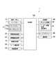
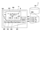
- FIG. 1 is a block diagram showing an image forming apparatus according to an embodiment of the present invention.
- FIG. 1 is a diagram showing a configuration of an image forming apparatus according to an embodiment of the present invention.
- 1 shows an image forming system according to an embodiment of the present invention.
- It is a block diagram showing a server computer concerning an embodiment of the present invention.
- It is a flowchart (the 1) of the box screen display process which concerns on embodiment of this invention.
- the 2 of the box screen display process which concerns on embodiment of this invention.
- It is a figure which shows the box list screen which concerns on embodiment of this invention.
- It is a flow chart of user information acquisition processing concerning an embodiment of the present invention.
- It is a figure which shows the user information acquisition screen which concerns on embodiment of this invention.
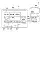
- FIG. 1 is a block diagram showing an image forming apparatus 1 according to the present embodiment.
- the image forming apparatus 1 is a multifunction peripheral, and has various functions such as a print function, a copy function, a scan function, a mail function (Send function), and a box function.
- the image forming apparatus 1 includes an operation panel 10, a document reading device 20, a document conveyance device 30, a communication unit 40, a sheet feeding device 50, a sheet conveyance unit 60, an image forming unit 70, a card scanner 80, A storage unit 90 and a control unit 100 are provided.
- Operation panel 10 receives an operation by a worker.
- the operation panel 10 displays various screens.
- the operation panel 10 includes the hard key 11 and the touch panel 12.
- the touch panel 12 includes a display 12 a and a touch sensor 12 b.
- the hard key 11 is an example of an operation unit, and receives an operation by a worker.
- the hard key 11 includes, for example, a start key, an arrow key, and a box key.
- the start key is a button for instructing to execute a job.
- the arrow key is a button for changing the selection object.
- the box key is a button for displaying a box list screen on the display 12a.
- the display 12a is an example of a display unit, and displays various screens.
- the display 12a is typically a liquid crystal display or an organic electroluminescence (EL) display.
- the display 12a displays a box screen and a box list screen.
- the touch sensor 12b is an example of the operation unit, and receives an operation by the operator. Specifically, the touch sensor 12b is disposed so as to overlap the display surface of the display 12a, and generates a signal corresponding to a gesture (typically, a finger gesture) on the display surface of the worker.
- the gestures include taps, flicks, swipes and the like.
- the touch sensor 12 b detects a touch by the worker and generates a signal indicating a touch position (touched position).
- the operator can input various instructions to the image forming apparatus 1 by means of a gesture.
- the document reading apparatus 20 reads a document image from a document to generate document image data.
- the document reading apparatus 20 includes a platen, and reads a document image from a document placed on the platen.
- the document conveyance device 30 conveys a document so as to pass through a predetermined document reading position.
- the document reading device 20 reads a document image from a document passing through a predetermined document reading position.
- the communication unit 40 connects to a network such as a LAN (Local Area Network), and executes communication with a user terminal such as a personal computer.
- the communication unit 40 is, for example, a network interface such as a LAN board.
- the communication unit 40 receives a print job including print image data from the user terminal. Further, the communication unit 40 transmits the electronic mail attached with the image data to the user terminal.
- the sheet feeding device 50 accommodates a plurality of sheets, and feeds the sheets to the sheet conveying unit 60 one by one.
- the sheet conveyance unit 60 conveys a sheet along a predetermined conveyance path.
- the image forming unit 70 forms an image on the sheet conveyed by the sheet conveyance unit 60. Specifically, the image forming unit 70 forms an image based on the print image data received by the communication unit 40 on a sheet. Alternatively, an image based on the document image data generated by the document reader 20 is formed on a sheet.
- the card scanner 80 reads an image recorded on the card and generates image data. Typically, the card scanner 80 optically reads the image recorded on the card.
- the image data generated by the card scanner 80 may be described as “card image data”.
- the card is an example of a recording medium
- the card scanner 80 is an example of an image reading unit.
- the card scanner 80 is an example of an input unit
- card image data is an example of input data.
- An image showing the identification information of the user is recorded on the card.
- the card scanner 80 reads an image indicating identification information of the user from the card, generates image data (card image data) indicating identification information of the user, and inputs the image data to the control unit 100.
- the identification information of the user may be described as "user information”.
- the card is, for example, a rectangular ID card, and an image indicating user information is printed on one main surface of the card. Specifically, on the ID card, an image indicating the name and identification number (ID number) of the user who holds the ID card is printed.
- the user information indicates the user's name (name information) and identification number (identification number information).
- name information a name image
- identification number information an image indicating the user's name
- an image indicating the identification number of the user may be described as an “identification number image”.
- the storage unit 90 stores various data or information.
- the storage unit 90 includes, for example, a hard disk drive (HDD), a random access memory (RAM), and a read only memory (ROM).
- the storage unit 90 stores user information 91.
- a box area 92 is set for each user information 91.
- the control unit 100 controls the operation of each unit of the image forming apparatus 1 by executing a control program (computer program) stored in the storage unit 90.
- the control unit 100 has a processor or arithmetic circuit such as, for example, a central processing unit (CPU) or a micro processing unit (MPU). Further, the control unit 100 may have an integrated circuit for image processing. An integrated circuit for image processing is typically configured by an application specific integrated circuit (ASIC).
- ASIC application specific integrated circuit
- the control unit 100 performs image processing on the image data stored in the storage unit 90 and converts the image data into image data for image formation (for printing).
- the control unit 100 controls the operation of each unit of the image forming apparatus 1 so that an image is formed on a sheet based on image data for image formation.
- control unit 100 determines whether or not there is a box area 92 corresponding to the user information indicated by the card image data. In other words, it is determined whether or not the box area 92 corresponding to the user information indicated by the card image data is set in the storage area of the storage unit 90.
- control unit 100 executes character recognition processing on card image data to acquire user information, and determines whether or not there is a box area 92 corresponding to the acquired user information. More specifically, the control unit 100 acquires user information by performing character recognition processing on a predetermined area of card image data.
- the predetermined area includes an area where the name image is arranged and an area where the identification number image is arranged.
- the character recognition process is typically an optical character recognition (OCR) process.
- the control unit 100 causes the display 12 a to display a box screen corresponding to the box area 92. In other words, a box screen corresponding to the user information acquired from the card is displayed.
- the control unit 100 sets the box area 92 corresponding to the user information.
- the user information acquired from the card image data is stored in the storage unit 90, and the box area 92 is newly set in association with the user information 91.
- the control unit 100 sets a box name and an account ID based on the user information 91.
- the account ID is set using the identification number of the user.
- a box name is set using the user's name and the user's identification number.
- the box number is set by a serial number. That is, a numerical value obtained by adding the numerical value "1" to the largest box number among the existing box numbers is set as the box number.
- a box can be newly created or registered without operating the operation panel 10 and setting a box number or the like. Therefore, it is possible to use the box function with a simple operation. Specifically, a box can be created by a simple operation. Thus, the work load on the worker can be reduced.
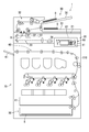
- FIG. 2 is a diagram showing the configuration of the image forming apparatus 1 according to the present embodiment.
- the image forming apparatus 1 is a tandem color multifunction peripheral.
- the image forming apparatus 1 further includes a sheet discharge tray 61 and a housing 110.
- the document reading device 20 includes a platen 21, a light source unit 22, an optical system 23, and an imaging device 24.
- the platen 21 is typically made of glass.
- the light source unit 22 includes a light source such as a light emitting diode (LED) and a reflection mirror.
- the light source unit 22 emits light to the document placed on the platen 21 while moving in the sub scanning direction X 1, and reflects light from the document to the optical system 23.
- the optical system 23 guides the reflected light to the imaging device 24, and the imaging device 24 images the reflected light to generate document image data.
- the imaging device 24 includes an imaging device such as a charge coupled device.
- the document conveyance device 30 includes a document placement tray 31, a document conveyance unit 32, and a document discharge tray 33.
- the documents D placed on the document placement tray 31 are conveyed by the document conveyance unit 32 to the document discharge tray 33 one by one.
- the document transport unit 32 includes a plurality of guide plates and a plurality of transport roller pairs. A plurality of guide plates form a predetermined conveyance path, and a plurality of conveyance roller pairs are arranged along the predetermined conveyance path.
- the document D is conveyed by rotation of the plurality of conveyance roller pairs. Specifically, the document D is conveyed to the document discharge tray 33 via the document reading position R.
- the light source unit 22 of the document reading device 20 is moved to a position facing the document reading position R.
- the light source unit 22 emits light to the document D passing through the document reading position R via the platen 21.
- the reflected light from the document D is guided to the imaging device 24, and document image data is generated.
- the sheet feeding device 50 includes a cassette 51 that is removable from the housing 110.
- the cassette 51 accommodates a plurality of sheets S.
- the sheet feeding device 50 feeds sheets S one by one from the cassette 51 to the sheet conveying unit 60.
- the sheet conveyance unit 60 includes a plurality of guide plates and a plurality of conveyance roller pairs.
- a plurality of guide plates form a predetermined conveyance path, and a plurality of conveyance roller pairs are arranged along the predetermined conveyance path.
- the sheet S is transported by rotation of the plurality of transport roller pairs. Specifically, the sheet S is conveyed to the sheet discharge tray 61 via the image forming unit 70.
- the image forming unit 70 forms an image on the sheet S by the electrophotographic method, heats and presses the image, and fixes the image on the sheet S.
- the image forming unit 70 includes a photosensitive drum, a charging device, an exposure device, a developing device, a transfer device, a charge removing device, and a fixing device, and an image is formed on the sheet S using toner. (Toner image) is formed.
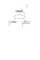
- FIG. 3 is a view showing an image forming system 5 according to the present embodiment.
- the image forming system 5 includes an image forming apparatus 1, a server computer 2, and a user terminal 3.
- the server computer 2 is an example of an external device.
- the image forming apparatus 1 is connected to the server computer 2 and the user terminal 3 via a network 4 such as a LAN.
- the communication unit 40 described with reference to FIG. 1 executes communication with the server computer 2 in addition to the user terminal 3.
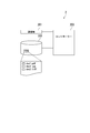
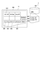
- FIG. 4 is a block diagram showing the server computer 2 according to the present embodiment.
- the server computer 2 includes a communication unit 201, a storage device 202, and a controller 203.
- the communication unit 201 is connected to the network 4 shown in FIG. 3 to execute communication with the image forming apparatus 1.
- the communication unit 201 is, for example, a network interface such as a LAN board.
- the communication unit 201 receives image data from the image forming apparatus 1.
- the communication unit 201 also transmits image data to the image forming apparatus 1.
- the storage device 202 stores the image data received by the communication unit 201 from the image forming apparatus 1.
- the storage device 202 is typically configured by a storage device such as an HDD.
- the controller 203 includes a processor or arithmetic circuit such as a CPU or an MPU.
- the controller 203 also includes a RAM and a ROM.
- the processor or arithmetic circuit executes a computer program stored in the ROM and the RAM to control the operation of each part of the server computer 2.
- the controller 203 stores the image data received from the image forming apparatus 1 in the storage device 202 in a file format.
- the storage device 202 stores image data in units of storage areas set for each piece of user information. Specifically, in response to a request from the image forming apparatus 1 (the control unit 100), the controller 203 causes the storage device 202 to store user information, and sets a storage area in association with the user information. Also, the controller 203 sets the name of the file using the user information. In the present embodiment, the controller 203 sets the file name using the identification number of the user.
- FIG. 4 shows that three files (image data) “doc1.pdf”, “doc2.jpg” and “doc3.tiff” are stored in the storage area (folder) associated with the identification number “1234”. Is illustrated.
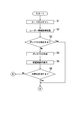
- FIGS. 5 and 6 are flowcharts of box screen display processing according to the present embodiment.
- the box screen display process shown in FIGS. 5 and 6 is started by setting the card in the card scanner 80 and instructing execution of the card scan.
- the card scanner 80 scans the card to generate card image data (step S1).
- the control unit 100 of the image forming apparatus 1 executes a process (user information acquisition process) of acquiring user information from the card image data (step S2).
- the control unit 100 of the image forming apparatus 1 determines whether there is a box corresponding to the acquired user information (step S3). Specifically, it is determined whether the box area 92 corresponding to the acquired user information is set in the storage unit 90 of the image forming apparatus 1 or not. For example, the control unit 100 determines whether the storage unit 90 stores user information 91 that matches the acquired user information.
- step S3 If the control unit 100 of the image forming apparatus 1 determines that there is a box corresponding to the user information (Yes in step S3), the process proceeds to step S7 illustrated in FIG.
- the control unit 100 of the image forming apparatus 1 determines that there is no box corresponding to the user information (No in step S3), the control unit 100 creates a box (step S4). Specifically, the acquired user information 91 is stored in the storage unit 90 of the image forming apparatus 1, and the box area 92 is set in association with the user information 91. For example, the control unit 100 sets an account ID of a newly created box using the identification number of the user. Also, the name of the newly created box is set using the user's name and the user's identification number.
- the control unit 100 of the image forming apparatus 1 displays a confirmation screen on the display 12a (step S5).
- the confirmation screen shows setting information of the newly created box. Specifically, the confirmation screen shows the box number of the newly created box, the box name, and the account ID. The confirmation screen will be described later with reference to FIG.
- step S6 When the worker permits the content of the setting information of the newly created box (Yes in step S6), the process proceeds to step S7 illustrated in FIG. On the other hand, when the worker does not permit the contents of the setting information of the newly created box, the process ends, as shown in FIG.
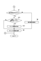
- step S3 determines that there is a box corresponding to the user information (Yes in step S3) or when the worker permits the contents of the setting information of the newly created box (Yes in step S6), as shown in FIG. 6, whether the control unit 100 of the image forming apparatus 1 has a storage area corresponding to the user information 91 acquired from the card image data in the storage device 202 of the server computer 2 It is determined whether or not (step S7). Specifically, it is determined whether the storage area (folder) corresponding to the acquired user information 91 is set in the storage area of the storage device 202 of the server computer 2 or not. For example, the control unit 100 determines whether or not the storage device 202 stores user information that matches the acquired user information 91.
- the control unit 100 of the image forming apparatus 1 determines that the storage area corresponding to the user information does not exist (No in step S7), the control unit 100 requests the server computer 2 to set the storage area.
- the controller 203 of the server computer 2 stores user information in the storage device 202, and sets a storage area in association with the user information (step S8).
- the file name is set using user information.
- the controller 203 stores the identification number of the user in the storage device 202, and sets the name of the file using the identification number of the user.
- the box area 92 corresponding to the user information does not exist (No in step S3 of FIG. 5)
- the storage area corresponding to the user information does not exist (No in step S7).
- control unit 100 of the image forming apparatus 1 causes the display 12a to display a box screen corresponding to the user information 91 acquired from the card image data (step S9), and ends the process.
- control unit 100 of the image forming apparatus 1 determines that the storage area corresponding to the user information exists (Yes in step S7), the control unit 100 determines whether the image data is stored in the storage area (step S10). .
- the storage area corresponding to the user information also exists (Yes in step S7).
- the display 12a displays a box screen corresponding to the user information 91 acquired from the card image data. After displaying (step S9), the process ends.
- control unit 100 of the image forming apparatus 1 determines that the image data is stored in the storage area (Yes in step S10), it generates link information for accessing the stored image data (step S11).
- the link information is typically path information specifying an area in which the image data is stored.
- the control unit 100 of the image forming apparatus 1 displays a box screen on the display 12a (step S9), and ends the process. Specifically, the control unit 100 of the image forming apparatus 1 generates a link image to which link information is added, and displays the link image on the box screen.
- the link image is typically a shortcut image.
- the storage area can be set in the storage area of the server computer 2 by a simple operation. Further, the link image can be displayed on the box screen by a simple operation. Therefore, even if the image data is stored not in the box area of the image forming apparatus 1 but in the storage area of the server computer 2, the box function can be used with a simple operation. Thus, the work load on the worker can be reduced.
- the worker transmits the image data stored in the server computer 2 to the image forming apparatus 1 by selecting the link image displayed on the box screen, and performs a job such as a print job. Can be performed. Therefore, since it is not necessary to store the image data in the box area 92, the storage capacity allocated to the box function can be reduced.
- the image forming system 5 which concerns on this embodiment can also display a box screen from a box list screen.
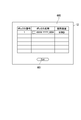
- FIG. 7 is a view showing a box list screen 600 according to the present embodiment.
- the box list screen 600 shows items of “box number”, “box name” and “used capacity” of the box registered in the image forming apparatus 1.
- “Used capacity” indicates the capacity of data stored in the corresponding box area 92.
- the operator can select one of the boxes displayed on the box list screen 600 by operating the hard key 11 or the touch panel 12 described with reference to FIG.
- the processes of step S10, step S11, and step S9 shown in FIG. 6 are executed, and a box screen is displayed on the touch panel 12.
- the box list screen 600 includes an “Exit” button 601.
- an “Exit” button 601. When the operator operates the hard key 11 or the touch panel 12 described with reference to FIG. 1 and inputs an instruction to press the “Exit” button 601, for example, a home screen is displayed on the touch panel 12.
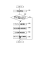
- FIG. 8 is a flowchart of user information acquisition processing according to the present embodiment.
- the control unit 100 of the image forming apparatus 1 executes an information acquisition process (step S21).
- the information acquisition process is a process of acquiring information from a predetermined area in card image data.
- the control unit 100 of the image forming apparatus 1 executes character recognition processing on a predetermined area in card image data.
- control unit 100 of the image forming apparatus 1 determines whether there is user information 91 that matches the acquired information (step S22). For example, the control unit 100 determines whether the storage unit 90 stores user information 91 that matches the information acquired by the information acquisition process.
- control unit 100 of the image forming apparatus 1 determines that there is user information 91 that matches the acquired information (Yes in step S22), the control unit 100 ends the user information acquisition process.
- the box screen display process described with reference to FIG. 5 proceeds from step S2 to step S3.
- control unit 100 of the image forming apparatus 1 determines that there is no user information 91 that matches the acquired information (No in step S22), the control unit 100 generates a preview image based on the card image data and displays it on the display 12a. (Step S23). Specifically, a user information acquisition screen including a preview image is displayed on the display 12a. The preview image shows the image recorded on the card.
- the user information acquisition screen will be described later with reference to FIG.
- the control unit 100 of the image forming apparatus 1 causes the display 12a to display a message prompting the operator to designate the identification number area (step S24).
- the identification number area is an area where an identification number image is displayed.
- the operator specifies an identification number area, for example, by moving a finger so as to trace the identification number image on the touch panel 12 displaying the preview image.
- the control unit 100 of the image forming apparatus 1 causes the display 12a to display a message prompting the operator to designate the name area (step S25).
- the name area is an area in which a name image is displayed. The operator designates the name area, for example, by moving a finger on the touch panel 12 displaying the preview image so as to trace the name image.
- control unit 100 of the image forming apparatus 1 acquires user information from the designated identification number area and the designated name area (step S26), and ends the user information acquisition process. Specifically, character recognition processing is performed on each designated area.
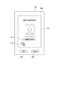
- FIG. 9 is a view showing a user information acquisition screen 700 according to the present embodiment.
- the user information acquisition screen 700 includes a preview image 710, an “OK” button 720, and a “Cancel” button 730.
- the preview image 710 shows the image recorded on the card, and includes a name image 711 and an identification number image 712.
- user information is acquired by the operator tracing the name image 711 and the identification number image 712 with a finger. Specifically, after the operator traces the name image 711 and the identification number image 712 with a finger, and then inputs an instruction to press the “OK” button 720, the control unit 100 of the image forming apparatus 1 traces the area with the finger. Get user information from On the other hand, when the operator traces the name image 711 and the identification number image 712 with a finger and then inputs an instruction to press the “Cancel” button 730, the designation of the area is cancelled.
- the operator can acquire user information by tracing the touch panel 12. Therefore, the box function can be used with a simple operation.
- the control unit 100 of the image forming apparatus 1 highlights the area where the operator has traced the touch panel 12.
- the worker can recognize the area traced by himself.
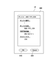
- FIG. 10 is a view showing a confirmation screen 800 according to the present embodiment.
- the confirmation screen 800 shows setting information of a box newly created by the control unit 100 of the image forming apparatus 1 as described with reference to FIG.
- the confirmation screen 800 shows “box number”, “box name”, “available capacity”, and “account ID” of the newly created box.
- the available capacity indicates the capacity of the storage area set in the server computer 2.
- the confirmation screen 800 includes an “OK” button 810 and a “Cancel” button 820.
- the operator inputs an instruction to press the “OK” button 810 (Yes in step S6 shown in FIG. 5)
- the setting information of the newly created box is confirmed.
- the operator inputs an instruction to press the “Cancel” button 820 (No in step S6 shown in FIG. 5)
- 11 to 13 show files (image data) stored in the storage device 202 of the server computer 2 in order to facilitate the description. Specifically, image data (file) stored in the storage area corresponding to the box screen 900 is shown.
- FIG. 11 is a view showing a box screen 900 according to the present embodiment. Specifically, a box screen 900 displayed when image data is not stored in the box area 92 and three files are stored in the corresponding storage area is shown.
- the box screen 900 includes a "Download” button 901, an "Upload” button 902, a “Store” button 903, a “Print” button 904, a "Send” button 905, a "Move / Copy” button 906, and a "Delete” button 907. Including.
- the image forming apparatus 1 forms an image corresponding to the image data transmitted from the server computer 2 on the sheet S. Further, when the operator inputs an instruction to press the “Send” button 905, the image forming apparatus 1 transmits an electronic mail attached with the image data transmitted from the server computer 2 to the designated user terminal 3 .
- the control unit 100 of the image forming apparatus 1 copies the image data transmitted from the server computer 2, and copies the copied data.
- the box area 92 of The destination of the e-mail can be designated from the address book, for example, before the “Send” button 905 is pressed.
- the box area 92 for transferring the copied image data can be selected from the box list screen, for example, before the “Move / Copy” button 906 is pressed.
- the “Print” button 904 when the “Store” button 903 is pressed and the image data is stored in the box area 92, the “Print” button 904, the “Send” button 905, the “Move / Copy” button 906, and the “Delete” button 907 are selected. Pressing is permitted. In this case, even if the “Print” button 904, the “Send” button 905, or the “Move / Copy” button 906 is pressed, the image data is not deleted from the box area 92. When deleting the image data from the box area 92, the operator inputs an instruction to press the “Delete” button 907. The “Delete” button 907 will be described later with reference to FIG.
- FIG. 12 is a view showing a box screen 900 according to the present embodiment. Specifically, a box screen 900 displayed when the document image data generated by the document reader 20 is stored in the box area 92 is shown.
- the control unit 100 of the image forming apparatus 1 when the document image data is stored in the box area 92, the control unit 100 of the image forming apparatus 1 generates a preview image 920 based on the document image data and causes the box screen 900 to display it.
- the control unit 100 of the image forming apparatus 1 corresponds to the server computer 2 as shown in FIG. 12 for the document image data stored in the box area 92. Save in the save area. Specifically, a new file (“doc4.jpg”) is created on the server computer 2.
- FIG. 13 is a view showing a box screen 900 according to the present embodiment. Specifically, FIG. 13 is displayed when an operator operates the hard key 11 or the touch panel 12 to input an instruction to select the preview image 920 and then inputs an instruction to press the “Delete” button 907. Dialog screen 930 is displayed.
- the dialog screen 930 includes a message M asking whether to delete the file to be deleted from the server computer 2.
- the file to be deleted is the file “doc4.jpg” corresponding to the preview image 920.
- the dialog screen 930 also includes a “Yes” button 931 and a “No” button 932.
- the control unit 100 of the image forming apparatus 1 deletes the image data (original image data corresponding to the preview image 920) to be deleted from the box area 92. . Further, the control unit 100 of the image forming apparatus 1 requests the controller 203 of the server computer 2 to delete the file to be deleted. As a result, the file to be erased is erased from the storage area of the server computer 2.
- the control unit 100 of the image forming apparatus 1 deletes the image data to be deleted from the box area 92. Also, link information for accessing the file to be deleted is generated, and the corresponding link image is displayed on the box screen 900.
- the printing process or the like based on the image data stored in the server computer 2 can be executed by a simple operation via the box screen 900. it can.
- the document image data is stored in the box area 92, and the document image data is stored in the storage area of the server computer 2 according to the operation of the worker. However, the document image data is generated. Then, the document image data may be stored in the storage area of the server computer 2 without being stored in the box area 92.
- the image data is deleted from the box area 92 by pressing the “Yes” button 931 or the “No” button 932 of the dialog screen 930 after the “Delete” button 907 is pressed.
- the image data may be erased from the box area 92 by pressing the button for transmitting the image data from the image forming apparatus 1 to the server computer 2.
- the card scanner 80 is used as an image reading unit that generates image data indicating user information, but the document reading device 20 is used to generate image data indicating user information May be
- a card is used as a recording medium on which an image indicating user information is recorded, but the recording medium may be, for example, a sheet.
- the image is scanned to generate the image data indicating the user information, but the image data indicating the user information may be acquired from the storage medium.
- the storage medium is, for example, a Universal Serial Bus (USB) memory or a Near Field Communication (NFC) tag.
- USB Universal Serial Bus
- NFC Near Field Communication
- the image forming apparatus 1 includes a USB terminal. Further, when using an NFC tag, the image forming apparatus 1 includes an NFC communication module.
- the input data indicating the identification information of the user is the image data, but the input data may be any data indicating the identification information of the user, and is not limited to the image data.
- the input data may be character data indicating identification information of the user.
- the image forming apparatus 1 is a multifunction peripheral, but the image forming apparatus 1 may be a printing machine, a copier, or a scanner.
- the image forming apparatus 1 is a color machine, but the image forming apparatus 1 may be a monochrome machine.
- the image forming apparatus 1 is an electrophotographic image forming apparatus.
- the image forming apparatus 1 may be an inkjet image forming apparatus.
- the image may be recorded by ejecting ink from the recording head to the sheet.
- the touch panel 12 is operated with a finger.
- the touch panel 12 may be operated using an operation member such as a touch pen (stylus pen).
- the present invention is useful for an image forming apparatus having a box function.
Abstract
L'invention concerne un appareil de formation d'image (1) qui est pourvu d'une unité de stockage (90), d'une unité d'entrée (80), d'une unité de commande (100) et d'une unité d'affichage (12). Dans l'unité de stockage (90), une région de boîte (92) est définie pour chaque élément d'informations d'identification d'utilisateur (91). Des données d'entrée indiquant des informations d'identification d'utilisateur sont entrées dans l'unité d'entrée (80). L'unité de commande (100) détermine si une région de boîte (92) correspondant aux informations d'identification indiquées par les données d'entrée est présente ou non. L'unité d'affichage (12) affiche un écran de boîte. L'unité de commande (100) amène l'unité d'affichage (12) à afficher l'écran de boîte si la région de boîte (92) correspondant aux informations d'identification indiquées par les données d'entrée est présente. L'unité de commande (100) définit la région de boîte (92) correspondant aux informations d'identification indiquées par les données d'entrée si la région de boîte (92) correspondant aux informations d'identification indiquées par les données d'entrée n'est pas présente.
Applications Claiming Priority (2)
| Application Number | Priority Date | Filing Date | Title |
|---|---|---|---|
| JP2017-212687 | 2017-11-02 | ||
| JP2017212687 | 2017-11-02 |
Publications (1)
| Publication Number | Publication Date |
|---|---|
| WO2019087604A1 true WO2019087604A1 (fr) | 2019-05-09 |
Family
ID=66333067
Family Applications (1)
| Application Number | Title | Priority Date | Filing Date |
|---|---|---|---|
| PCT/JP2018/034626 WO2019087604A1 (fr) | 2017-11-02 | 2018-09-19 | Appareil de formation d'image et système de formation d'image |
Country Status (1)
| Country | Link |
|---|---|
| WO (1) | WO2019087604A1 (fr) |
Citations (6)
| Publication number | Priority date | Publication date | Assignee | Title |
|---|---|---|---|---|
| JP2006260464A (ja) * | 2005-03-18 | 2006-09-28 | Konica Minolta Business Technologies Inc | 文書管理装置及び文書管理プログラム |
| JP2006319919A (ja) * | 2005-05-16 | 2006-11-24 | Canon Inc | 画像処理装置及びその制御方法、表示制御装置及びその制御方法、並びに制御プログラム |
| JP2008040958A (ja) * | 2006-08-09 | 2008-02-21 | Konica Minolta Business Technologies Inc | 電子文書管理装置、電子文書管理方法、電子文書管理プログラム、および電子文書を作成するためのプログラム |
| JP2009095006A (ja) * | 2007-09-21 | 2009-04-30 | Canon Inc | 画像形成装置、方法、プログラム |
| JP2011076216A (ja) * | 2009-09-29 | 2011-04-14 | Canon Inc | 画像処理装置、その認証方法およびプログラム |
| JP2017108426A (ja) * | 2017-01-24 | 2017-06-15 | ブラザー工業株式会社 | 情報処理装置及びネットワークシステム |
-
2018
- 2018-09-19 WO PCT/JP2018/034626 patent/WO2019087604A1/fr active Application Filing
Patent Citations (6)
| Publication number | Priority date | Publication date | Assignee | Title |
|---|---|---|---|---|
| JP2006260464A (ja) * | 2005-03-18 | 2006-09-28 | Konica Minolta Business Technologies Inc | 文書管理装置及び文書管理プログラム |
| JP2006319919A (ja) * | 2005-05-16 | 2006-11-24 | Canon Inc | 画像処理装置及びその制御方法、表示制御装置及びその制御方法、並びに制御プログラム |
| JP2008040958A (ja) * | 2006-08-09 | 2008-02-21 | Konica Minolta Business Technologies Inc | 電子文書管理装置、電子文書管理方法、電子文書管理プログラム、および電子文書を作成するためのプログラム |
| JP2009095006A (ja) * | 2007-09-21 | 2009-04-30 | Canon Inc | 画像形成装置、方法、プログラム |
| JP2011076216A (ja) * | 2009-09-29 | 2011-04-14 | Canon Inc | 画像処理装置、その認証方法およびプログラム |
| JP2017108426A (ja) * | 2017-01-24 | 2017-06-15 | ブラザー工業株式会社 | 情報処理装置及びネットワークシステム |
Similar Documents
| Publication | Publication Date | Title |
|---|---|---|
| JP4665992B2 (ja) | 印刷制御装置および印刷装置 | |
| CN107959762B (zh) | 处理装置、记录介质以及代理处理设定方法 | |
| US11611668B2 (en) | Image processing system that generates job setting information based on interaction with user of information processing apparatus using chatbot | |
| US11588951B2 (en) | Image forming apparatus | |
| US10974516B2 (en) | Device, method for controlling device, and storage medium | |
| JP6222242B2 (ja) | 画像処理装置及び画像処理システム | |
| JP2008219106A (ja) | 画像読取装置 | |
| JP2019009689A (ja) | 画像形成装置 | |
| US10694054B2 (en) | Information processing apparatus, image reading apparatus, image forming apparatus, and non-transitory computer readable medium | |
| US20180084122A1 (en) | Processing device, image forming apparatus, and non-transitory computer readable medium | |
| WO2019087604A1 (fr) | Appareil de formation d'image et système de formation d'image | |
| US11108924B2 (en) | Image forming apparatus | |
| US9538026B2 (en) | Display apparatus, image processing apparatus, display method, and computer readable medium for controlling an operation of a display process | |
| US9131074B2 (en) | Information processing apparatus, printing apparatus, printing system, and computer-readable non-transitory storage medium | |
| JP2013257770A (ja) | 印刷制御装置、印刷制御装置の制御プログラム、印刷制御装置の制御方法 | |
| JP2014030080A (ja) | 画像処理装置及び画像処理方法 | |
| JP5847669B2 (ja) | 操作装置および電子機器 | |
| CN108881658B (zh) | 数据传送装置、图像形成装置以及图像读取装置 | |
| JP2023006640A (ja) | 印刷支援装置、印刷支援方法および印刷支援プログラム | |
| JP6054494B2 (ja) | 操作装置および電子機器 | |
| JP2017005635A (ja) | 画像形成装置 | |
| JP2023054582A (ja) | 画像形成装置 | |
| JP2022168990A (ja) | 画像形成装置、画像形成装置における画面表示方法およびプログラム | |
| JP2022109360A (ja) | 画像形成装置、画像形成システム、画像形成装置の制御プログラムおよび制御方法 | |
| JP2022019049A (ja) | 画像形成装置、画像形成装置を含む印刷システム、画像形成装置の制御プログラムおよび制御方法 |
Legal Events
| Date | Code | Title | Description |
|---|---|---|---|
| 121 | Ep: the epo has been informed by wipo that ep was designated in this application |
Ref document number: 18874199 Country of ref document: EP Kind code of ref document: A1 |
|
| NENP | Non-entry into the national phase |
Ref country code: DE |
|
| 122 | Ep: pct application non-entry in european phase |
Ref document number: 18874199 Country of ref document: EP Kind code of ref document: A1 |
|
| NENP | Non-entry into the national phase |
Ref country code: JP |