WO2019087604A1 - Image formation apparatus and image formation system - Google Patents
Image formation apparatus and image formation system Download PDFInfo
- Publication number
- WO2019087604A1 WO2019087604A1 PCT/JP2018/034626 JP2018034626W WO2019087604A1 WO 2019087604 A1 WO2019087604 A1 WO 2019087604A1 JP 2018034626 W JP2018034626 W JP 2018034626W WO 2019087604 A1 WO2019087604 A1 WO 2019087604A1
- Authority
- WO
- WIPO (PCT)
- Prior art keywords
- identification information
- box
- image
- image forming
- image data
- Prior art date
Links
Images
Classifications
-
- B—PERFORMING OPERATIONS; TRANSPORTING
- B41—PRINTING; LINING MACHINES; TYPEWRITERS; STAMPS
- B41J—TYPEWRITERS; SELECTIVE PRINTING MECHANISMS, i.e. MECHANISMS PRINTING OTHERWISE THAN FROM A FORME; CORRECTION OF TYPOGRAPHICAL ERRORS
- B41J29/00—Details of, or accessories for, typewriters or selective printing mechanisms not otherwise provided for
- B41J29/38—Drives, motors, controls or automatic cut-off devices for the entire printing mechanism
-
- B—PERFORMING OPERATIONS; TRANSPORTING
- B41—PRINTING; LINING MACHINES; TYPEWRITERS; STAMPS
- B41J—TYPEWRITERS; SELECTIVE PRINTING MECHANISMS, i.e. MECHANISMS PRINTING OTHERWISE THAN FROM A FORME; CORRECTION OF TYPOGRAPHICAL ERRORS
- B41J29/00—Details of, or accessories for, typewriters or selective printing mechanisms not otherwise provided for
- B41J29/42—Scales and indicators, e.g. for determining side margins
-
- G—PHYSICS
- G03—PHOTOGRAPHY; CINEMATOGRAPHY; ANALOGOUS TECHNIQUES USING WAVES OTHER THAN OPTICAL WAVES; ELECTROGRAPHY; HOLOGRAPHY
- G03G—ELECTROGRAPHY; ELECTROPHOTOGRAPHY; MAGNETOGRAPHY
- G03G21/00—Arrangements not provided for by groups G03G13/00 - G03G19/00, e.g. cleaning, elimination of residual charge
-
- G—PHYSICS
- G06—COMPUTING; CALCULATING OR COUNTING
- G06F—ELECTRIC DIGITAL DATA PROCESSING
- G06F12/00—Accessing, addressing or allocating within memory systems or architectures
-
- G—PHYSICS
- G06—COMPUTING; CALCULATING OR COUNTING
- G06T—IMAGE DATA PROCESSING OR GENERATION, IN GENERAL
- G06T1/00—General purpose image data processing
-
- H—ELECTRICITY
- H04—ELECTRIC COMMUNICATION TECHNIQUE
- H04N—PICTORIAL COMMUNICATION, e.g. TELEVISION
- H04N1/00—Scanning, transmission or reproduction of documents or the like, e.g. facsimile transmission; Details thereof
-
- H—ELECTRICITY
- H04—ELECTRIC COMMUNICATION TECHNIQUE
- H04N—PICTORIAL COMMUNICATION, e.g. TELEVISION
- H04N1/00—Scanning, transmission or reproduction of documents or the like, e.g. facsimile transmission; Details thereof
- H04N1/21—Intermediate information storage
Definitions
- the present invention relates to an image forming apparatus and an image forming system.
- an image forming apparatus such as a multifunction peripheral has a box function.
- the box is usually created by the administrator operating the operation panel. Specifically, when creating a private box or a user box, the administrator operates the operation panel to input a box number, a box name, and an account ID (see, for example, Patent Document 1).
- An object of the present invention is to provide an image forming apparatus and an image forming system capable of utilizing a box function by a simple operation.
- An image forming apparatus includes a storage unit, an input unit, a control unit, and a display unit.
- a box area is set in the storage unit for each user identification information.
- the input unit inputs input data indicating identification information of the user.
- the control unit determines whether the box area corresponding to the identification information indicated by the input data is present.
- the display unit displays a box screen.
- the control unit causes the display unit to display the box screen corresponding to the identification information, when the box area corresponding to the identification information exists.
- the control unit sets the box area corresponding to the identification information when the box area corresponding to the identification information does not exist.
- An image forming system includes an external apparatus and an image forming apparatus.
- the external device stores image data in units of storage areas set for each identification information of the user.
- the image forming apparatus includes a communication unit, a storage unit, an input unit, a control unit, and a display unit.
- the communication unit executes communication with the external device.
- a box area is set in the storage unit for each identification information of the user.
- the input unit inputs input data indicating identification information of the user.
- the control unit determines whether the box area corresponding to the identification information indicated by the input data is present.
- the display unit displays a box screen.
- the control unit generates link information for accessing the image data stored in the storage area corresponding to the identification information when the box area corresponding to the identification information exists.
- the display unit displays the box screen corresponding to the information and a link image indicating the link information.
- the control unit sets the box area corresponding to the identification information when the box area corresponding to the identification information does not exist.
- the image forming apparatus includes a communication unit, a storage unit, an input unit, a control unit, and a display unit.
- the communication unit executes communication with the external device.
- a box area is set in the storage unit for each identification information of the user.
- the input unit inputs input data indicating identification information of the user.
- the control unit generates link information for accessing the image data stored in the storage area corresponding to the identification information indicated by the input data.
- the display unit displays a box screen corresponding to the identification information indicated by the input data.
- the control unit displays a link image indicating the link information on the box screen.
- FIG. 1 is a block diagram showing an image forming apparatus according to an embodiment of the present invention.
- FIG. 1 is a diagram showing a configuration of an image forming apparatus according to an embodiment of the present invention.
- 1 shows an image forming system according to an embodiment of the present invention.
- It is a block diagram showing a server computer concerning an embodiment of the present invention.
- It is a flowchart (the 1) of the box screen display process which concerns on embodiment of this invention.
- the 2 of the box screen display process which concerns on embodiment of this invention.
- It is a figure which shows the box list screen which concerns on embodiment of this invention.
- It is a flow chart of user information acquisition processing concerning an embodiment of the present invention.
- It is a figure which shows the user information acquisition screen which concerns on embodiment of this invention.
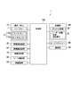
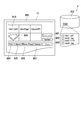
- FIG. 1 is a block diagram showing an image forming apparatus 1 according to the present embodiment.
- the image forming apparatus 1 is a multifunction peripheral, and has various functions such as a print function, a copy function, a scan function, a mail function (Send function), and a box function.
- the image forming apparatus 1 includes an operation panel 10, a document reading device 20, a document conveyance device 30, a communication unit 40, a sheet feeding device 50, a sheet conveyance unit 60, an image forming unit 70, a card scanner 80, A storage unit 90 and a control unit 100 are provided.
- Operation panel 10 receives an operation by a worker.
- the operation panel 10 displays various screens.
- the operation panel 10 includes the hard key 11 and the touch panel 12.
- the touch panel 12 includes a display 12 a and a touch sensor 12 b.
- the hard key 11 is an example of an operation unit, and receives an operation by a worker.
- the hard key 11 includes, for example, a start key, an arrow key, and a box key.
- the start key is a button for instructing to execute a job.
- the arrow key is a button for changing the selection object.
- the box key is a button for displaying a box list screen on the display 12a.
- the display 12a is an example of a display unit, and displays various screens.
- the display 12a is typically a liquid crystal display or an organic electroluminescence (EL) display.
- the display 12a displays a box screen and a box list screen.
- the touch sensor 12b is an example of the operation unit, and receives an operation by the operator. Specifically, the touch sensor 12b is disposed so as to overlap the display surface of the display 12a, and generates a signal corresponding to a gesture (typically, a finger gesture) on the display surface of the worker.
- the gestures include taps, flicks, swipes and the like.
- the touch sensor 12 b detects a touch by the worker and generates a signal indicating a touch position (touched position).
- the operator can input various instructions to the image forming apparatus 1 by means of a gesture.
- the document reading apparatus 20 reads a document image from a document to generate document image data.
- the document reading apparatus 20 includes a platen, and reads a document image from a document placed on the platen.
- the document conveyance device 30 conveys a document so as to pass through a predetermined document reading position.
- the document reading device 20 reads a document image from a document passing through a predetermined document reading position.
- the communication unit 40 connects to a network such as a LAN (Local Area Network), and executes communication with a user terminal such as a personal computer.
- the communication unit 40 is, for example, a network interface such as a LAN board.
- the communication unit 40 receives a print job including print image data from the user terminal. Further, the communication unit 40 transmits the electronic mail attached with the image data to the user terminal.
- the sheet feeding device 50 accommodates a plurality of sheets, and feeds the sheets to the sheet conveying unit 60 one by one.
- the sheet conveyance unit 60 conveys a sheet along a predetermined conveyance path.
- the image forming unit 70 forms an image on the sheet conveyed by the sheet conveyance unit 60. Specifically, the image forming unit 70 forms an image based on the print image data received by the communication unit 40 on a sheet. Alternatively, an image based on the document image data generated by the document reader 20 is formed on a sheet.
- the card scanner 80 reads an image recorded on the card and generates image data. Typically, the card scanner 80 optically reads the image recorded on the card.
- the image data generated by the card scanner 80 may be described as “card image data”.
- the card is an example of a recording medium
- the card scanner 80 is an example of an image reading unit.
- the card scanner 80 is an example of an input unit
- card image data is an example of input data.
- An image showing the identification information of the user is recorded on the card.
- the card scanner 80 reads an image indicating identification information of the user from the card, generates image data (card image data) indicating identification information of the user, and inputs the image data to the control unit 100.
- the identification information of the user may be described as "user information”.
- the card is, for example, a rectangular ID card, and an image indicating user information is printed on one main surface of the card. Specifically, on the ID card, an image indicating the name and identification number (ID number) of the user who holds the ID card is printed.
- the user information indicates the user's name (name information) and identification number (identification number information).
- name information a name image
- identification number information an image indicating the user's name
- an image indicating the identification number of the user may be described as an “identification number image”.
- the storage unit 90 stores various data or information.
- the storage unit 90 includes, for example, a hard disk drive (HDD), a random access memory (RAM), and a read only memory (ROM).
- the storage unit 90 stores user information 91.
- a box area 92 is set for each user information 91.
- the control unit 100 controls the operation of each unit of the image forming apparatus 1 by executing a control program (computer program) stored in the storage unit 90.
- the control unit 100 has a processor or arithmetic circuit such as, for example, a central processing unit (CPU) or a micro processing unit (MPU). Further, the control unit 100 may have an integrated circuit for image processing. An integrated circuit for image processing is typically configured by an application specific integrated circuit (ASIC).
- ASIC application specific integrated circuit
- the control unit 100 performs image processing on the image data stored in the storage unit 90 and converts the image data into image data for image formation (for printing).
- the control unit 100 controls the operation of each unit of the image forming apparatus 1 so that an image is formed on a sheet based on image data for image formation.
- control unit 100 determines whether or not there is a box area 92 corresponding to the user information indicated by the card image data. In other words, it is determined whether or not the box area 92 corresponding to the user information indicated by the card image data is set in the storage area of the storage unit 90.
- control unit 100 executes character recognition processing on card image data to acquire user information, and determines whether or not there is a box area 92 corresponding to the acquired user information. More specifically, the control unit 100 acquires user information by performing character recognition processing on a predetermined area of card image data.
- the predetermined area includes an area where the name image is arranged and an area where the identification number image is arranged.
- the character recognition process is typically an optical character recognition (OCR) process.
- the control unit 100 causes the display 12 a to display a box screen corresponding to the box area 92. In other words, a box screen corresponding to the user information acquired from the card is displayed.
- the control unit 100 sets the box area 92 corresponding to the user information.
- the user information acquired from the card image data is stored in the storage unit 90, and the box area 92 is newly set in association with the user information 91.
- the control unit 100 sets a box name and an account ID based on the user information 91.
- the account ID is set using the identification number of the user.
- a box name is set using the user's name and the user's identification number.
- the box number is set by a serial number. That is, a numerical value obtained by adding the numerical value "1" to the largest box number among the existing box numbers is set as the box number.
- a box can be newly created or registered without operating the operation panel 10 and setting a box number or the like. Therefore, it is possible to use the box function with a simple operation. Specifically, a box can be created by a simple operation. Thus, the work load on the worker can be reduced.
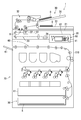
- FIG. 2 is a diagram showing the configuration of the image forming apparatus 1 according to the present embodiment.
- the image forming apparatus 1 is a tandem color multifunction peripheral.
- the image forming apparatus 1 further includes a sheet discharge tray 61 and a housing 110.
- the document reading device 20 includes a platen 21, a light source unit 22, an optical system 23, and an imaging device 24.
- the platen 21 is typically made of glass.
- the light source unit 22 includes a light source such as a light emitting diode (LED) and a reflection mirror.
- the light source unit 22 emits light to the document placed on the platen 21 while moving in the sub scanning direction X 1, and reflects light from the document to the optical system 23.
- the optical system 23 guides the reflected light to the imaging device 24, and the imaging device 24 images the reflected light to generate document image data.
- the imaging device 24 includes an imaging device such as a charge coupled device.
- the document conveyance device 30 includes a document placement tray 31, a document conveyance unit 32, and a document discharge tray 33.
- the documents D placed on the document placement tray 31 are conveyed by the document conveyance unit 32 to the document discharge tray 33 one by one.
- the document transport unit 32 includes a plurality of guide plates and a plurality of transport roller pairs. A plurality of guide plates form a predetermined conveyance path, and a plurality of conveyance roller pairs are arranged along the predetermined conveyance path.
- the document D is conveyed by rotation of the plurality of conveyance roller pairs. Specifically, the document D is conveyed to the document discharge tray 33 via the document reading position R.
- the light source unit 22 of the document reading device 20 is moved to a position facing the document reading position R.
- the light source unit 22 emits light to the document D passing through the document reading position R via the platen 21.
- the reflected light from the document D is guided to the imaging device 24, and document image data is generated.
- the sheet feeding device 50 includes a cassette 51 that is removable from the housing 110.
- the cassette 51 accommodates a plurality of sheets S.
- the sheet feeding device 50 feeds sheets S one by one from the cassette 51 to the sheet conveying unit 60.
- the sheet conveyance unit 60 includes a plurality of guide plates and a plurality of conveyance roller pairs.
- a plurality of guide plates form a predetermined conveyance path, and a plurality of conveyance roller pairs are arranged along the predetermined conveyance path.
- the sheet S is transported by rotation of the plurality of transport roller pairs. Specifically, the sheet S is conveyed to the sheet discharge tray 61 via the image forming unit 70.
- the image forming unit 70 forms an image on the sheet S by the electrophotographic method, heats and presses the image, and fixes the image on the sheet S.
- the image forming unit 70 includes a photosensitive drum, a charging device, an exposure device, a developing device, a transfer device, a charge removing device, and a fixing device, and an image is formed on the sheet S using toner. (Toner image) is formed.
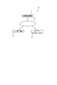
- FIG. 3 is a view showing an image forming system 5 according to the present embodiment.
- the image forming system 5 includes an image forming apparatus 1, a server computer 2, and a user terminal 3.
- the server computer 2 is an example of an external device.
- the image forming apparatus 1 is connected to the server computer 2 and the user terminal 3 via a network 4 such as a LAN.
- the communication unit 40 described with reference to FIG. 1 executes communication with the server computer 2 in addition to the user terminal 3.
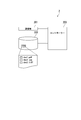
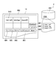
- FIG. 4 is a block diagram showing the server computer 2 according to the present embodiment.
- the server computer 2 includes a communication unit 201, a storage device 202, and a controller 203.
- the communication unit 201 is connected to the network 4 shown in FIG. 3 to execute communication with the image forming apparatus 1.
- the communication unit 201 is, for example, a network interface such as a LAN board.
- the communication unit 201 receives image data from the image forming apparatus 1.
- the communication unit 201 also transmits image data to the image forming apparatus 1.
- the storage device 202 stores the image data received by the communication unit 201 from the image forming apparatus 1.
- the storage device 202 is typically configured by a storage device such as an HDD.
- the controller 203 includes a processor or arithmetic circuit such as a CPU or an MPU.
- the controller 203 also includes a RAM and a ROM.
- the processor or arithmetic circuit executes a computer program stored in the ROM and the RAM to control the operation of each part of the server computer 2.
- the controller 203 stores the image data received from the image forming apparatus 1 in the storage device 202 in a file format.
- the storage device 202 stores image data in units of storage areas set for each piece of user information. Specifically, in response to a request from the image forming apparatus 1 (the control unit 100), the controller 203 causes the storage device 202 to store user information, and sets a storage area in association with the user information. Also, the controller 203 sets the name of the file using the user information. In the present embodiment, the controller 203 sets the file name using the identification number of the user.
- FIG. 4 shows that three files (image data) “doc1.pdf”, “doc2.jpg” and “doc3.tiff” are stored in the storage area (folder) associated with the identification number “1234”. Is illustrated.
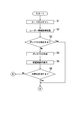
- FIGS. 5 and 6 are flowcharts of box screen display processing according to the present embodiment.
- the box screen display process shown in FIGS. 5 and 6 is started by setting the card in the card scanner 80 and instructing execution of the card scan.
- the card scanner 80 scans the card to generate card image data (step S1).
- the control unit 100 of the image forming apparatus 1 executes a process (user information acquisition process) of acquiring user information from the card image data (step S2).
- the control unit 100 of the image forming apparatus 1 determines whether there is a box corresponding to the acquired user information (step S3). Specifically, it is determined whether the box area 92 corresponding to the acquired user information is set in the storage unit 90 of the image forming apparatus 1 or not. For example, the control unit 100 determines whether the storage unit 90 stores user information 91 that matches the acquired user information.
- step S3 If the control unit 100 of the image forming apparatus 1 determines that there is a box corresponding to the user information (Yes in step S3), the process proceeds to step S7 illustrated in FIG.
- the control unit 100 of the image forming apparatus 1 determines that there is no box corresponding to the user information (No in step S3), the control unit 100 creates a box (step S4). Specifically, the acquired user information 91 is stored in the storage unit 90 of the image forming apparatus 1, and the box area 92 is set in association with the user information 91. For example, the control unit 100 sets an account ID of a newly created box using the identification number of the user. Also, the name of the newly created box is set using the user's name and the user's identification number.
- the control unit 100 of the image forming apparatus 1 displays a confirmation screen on the display 12a (step S5).
- the confirmation screen shows setting information of the newly created box. Specifically, the confirmation screen shows the box number of the newly created box, the box name, and the account ID. The confirmation screen will be described later with reference to FIG.
- step S6 When the worker permits the content of the setting information of the newly created box (Yes in step S6), the process proceeds to step S7 illustrated in FIG. On the other hand, when the worker does not permit the contents of the setting information of the newly created box, the process ends, as shown in FIG.
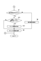
- step S3 determines that there is a box corresponding to the user information (Yes in step S3) or when the worker permits the contents of the setting information of the newly created box (Yes in step S6), as shown in FIG. 6, whether the control unit 100 of the image forming apparatus 1 has a storage area corresponding to the user information 91 acquired from the card image data in the storage device 202 of the server computer 2 It is determined whether or not (step S7). Specifically, it is determined whether the storage area (folder) corresponding to the acquired user information 91 is set in the storage area of the storage device 202 of the server computer 2 or not. For example, the control unit 100 determines whether or not the storage device 202 stores user information that matches the acquired user information 91.
- the control unit 100 of the image forming apparatus 1 determines that the storage area corresponding to the user information does not exist (No in step S7), the control unit 100 requests the server computer 2 to set the storage area.
- the controller 203 of the server computer 2 stores user information in the storage device 202, and sets a storage area in association with the user information (step S8).
- the file name is set using user information.
- the controller 203 stores the identification number of the user in the storage device 202, and sets the name of the file using the identification number of the user.
- the box area 92 corresponding to the user information does not exist (No in step S3 of FIG. 5)
- the storage area corresponding to the user information does not exist (No in step S7).
- control unit 100 of the image forming apparatus 1 causes the display 12a to display a box screen corresponding to the user information 91 acquired from the card image data (step S9), and ends the process.
- control unit 100 of the image forming apparatus 1 determines that the storage area corresponding to the user information exists (Yes in step S7), the control unit 100 determines whether the image data is stored in the storage area (step S10). .
- the storage area corresponding to the user information also exists (Yes in step S7).
- the display 12a displays a box screen corresponding to the user information 91 acquired from the card image data. After displaying (step S9), the process ends.
- control unit 100 of the image forming apparatus 1 determines that the image data is stored in the storage area (Yes in step S10), it generates link information for accessing the stored image data (step S11).
- the link information is typically path information specifying an area in which the image data is stored.
- the control unit 100 of the image forming apparatus 1 displays a box screen on the display 12a (step S9), and ends the process. Specifically, the control unit 100 of the image forming apparatus 1 generates a link image to which link information is added, and displays the link image on the box screen.
- the link image is typically a shortcut image.
- the storage area can be set in the storage area of the server computer 2 by a simple operation. Further, the link image can be displayed on the box screen by a simple operation. Therefore, even if the image data is stored not in the box area of the image forming apparatus 1 but in the storage area of the server computer 2, the box function can be used with a simple operation. Thus, the work load on the worker can be reduced.
- the worker transmits the image data stored in the server computer 2 to the image forming apparatus 1 by selecting the link image displayed on the box screen, and performs a job such as a print job. Can be performed. Therefore, since it is not necessary to store the image data in the box area 92, the storage capacity allocated to the box function can be reduced.
- the image forming system 5 which concerns on this embodiment can also display a box screen from a box list screen.
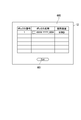
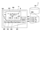
- FIG. 7 is a view showing a box list screen 600 according to the present embodiment.
- the box list screen 600 shows items of “box number”, “box name” and “used capacity” of the box registered in the image forming apparatus 1.
- “Used capacity” indicates the capacity of data stored in the corresponding box area 92.
- the operator can select one of the boxes displayed on the box list screen 600 by operating the hard key 11 or the touch panel 12 described with reference to FIG.
- the processes of step S10, step S11, and step S9 shown in FIG. 6 are executed, and a box screen is displayed on the touch panel 12.
- the box list screen 600 includes an “Exit” button 601.
- an “Exit” button 601. When the operator operates the hard key 11 or the touch panel 12 described with reference to FIG. 1 and inputs an instruction to press the “Exit” button 601, for example, a home screen is displayed on the touch panel 12.
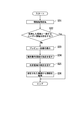
- FIG. 8 is a flowchart of user information acquisition processing according to the present embodiment.
- the control unit 100 of the image forming apparatus 1 executes an information acquisition process (step S21).
- the information acquisition process is a process of acquiring information from a predetermined area in card image data.
- the control unit 100 of the image forming apparatus 1 executes character recognition processing on a predetermined area in card image data.
- control unit 100 of the image forming apparatus 1 determines whether there is user information 91 that matches the acquired information (step S22). For example, the control unit 100 determines whether the storage unit 90 stores user information 91 that matches the information acquired by the information acquisition process.
- control unit 100 of the image forming apparatus 1 determines that there is user information 91 that matches the acquired information (Yes in step S22), the control unit 100 ends the user information acquisition process.
- the box screen display process described with reference to FIG. 5 proceeds from step S2 to step S3.
- control unit 100 of the image forming apparatus 1 determines that there is no user information 91 that matches the acquired information (No in step S22), the control unit 100 generates a preview image based on the card image data and displays it on the display 12a. (Step S23). Specifically, a user information acquisition screen including a preview image is displayed on the display 12a. The preview image shows the image recorded on the card.
- the user information acquisition screen will be described later with reference to FIG.
- the control unit 100 of the image forming apparatus 1 causes the display 12a to display a message prompting the operator to designate the identification number area (step S24).
- the identification number area is an area where an identification number image is displayed.
- the operator specifies an identification number area, for example, by moving a finger so as to trace the identification number image on the touch panel 12 displaying the preview image.
- the control unit 100 of the image forming apparatus 1 causes the display 12a to display a message prompting the operator to designate the name area (step S25).
- the name area is an area in which a name image is displayed. The operator designates the name area, for example, by moving a finger on the touch panel 12 displaying the preview image so as to trace the name image.
- control unit 100 of the image forming apparatus 1 acquires user information from the designated identification number area and the designated name area (step S26), and ends the user information acquisition process. Specifically, character recognition processing is performed on each designated area.
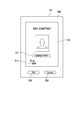
- FIG. 9 is a view showing a user information acquisition screen 700 according to the present embodiment.
- the user information acquisition screen 700 includes a preview image 710, an “OK” button 720, and a “Cancel” button 730.
- the preview image 710 shows the image recorded on the card, and includes a name image 711 and an identification number image 712.
- user information is acquired by the operator tracing the name image 711 and the identification number image 712 with a finger. Specifically, after the operator traces the name image 711 and the identification number image 712 with a finger, and then inputs an instruction to press the “OK” button 720, the control unit 100 of the image forming apparatus 1 traces the area with the finger. Get user information from On the other hand, when the operator traces the name image 711 and the identification number image 712 with a finger and then inputs an instruction to press the “Cancel” button 730, the designation of the area is cancelled.
- the operator can acquire user information by tracing the touch panel 12. Therefore, the box function can be used with a simple operation.
- the control unit 100 of the image forming apparatus 1 highlights the area where the operator has traced the touch panel 12.
- the worker can recognize the area traced by himself.
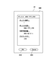
- FIG. 10 is a view showing a confirmation screen 800 according to the present embodiment.
- the confirmation screen 800 shows setting information of a box newly created by the control unit 100 of the image forming apparatus 1 as described with reference to FIG.
- the confirmation screen 800 shows “box number”, “box name”, “available capacity”, and “account ID” of the newly created box.
- the available capacity indicates the capacity of the storage area set in the server computer 2.
- the confirmation screen 800 includes an “OK” button 810 and a “Cancel” button 820.
- the operator inputs an instruction to press the “OK” button 810 (Yes in step S6 shown in FIG. 5)
- the setting information of the newly created box is confirmed.
- the operator inputs an instruction to press the “Cancel” button 820 (No in step S6 shown in FIG. 5)
- 11 to 13 show files (image data) stored in the storage device 202 of the server computer 2 in order to facilitate the description. Specifically, image data (file) stored in the storage area corresponding to the box screen 900 is shown.
- FIG. 11 is a view showing a box screen 900 according to the present embodiment. Specifically, a box screen 900 displayed when image data is not stored in the box area 92 and three files are stored in the corresponding storage area is shown.
- the box screen 900 includes a "Download” button 901, an "Upload” button 902, a “Store” button 903, a “Print” button 904, a "Send” button 905, a "Move / Copy” button 906, and a "Delete” button 907. Including.
- the image forming apparatus 1 forms an image corresponding to the image data transmitted from the server computer 2 on the sheet S. Further, when the operator inputs an instruction to press the “Send” button 905, the image forming apparatus 1 transmits an electronic mail attached with the image data transmitted from the server computer 2 to the designated user terminal 3 .
- the control unit 100 of the image forming apparatus 1 copies the image data transmitted from the server computer 2, and copies the copied data.
- the box area 92 of The destination of the e-mail can be designated from the address book, for example, before the “Send” button 905 is pressed.
- the box area 92 for transferring the copied image data can be selected from the box list screen, for example, before the “Move / Copy” button 906 is pressed.
- the “Print” button 904 when the “Store” button 903 is pressed and the image data is stored in the box area 92, the “Print” button 904, the “Send” button 905, the “Move / Copy” button 906, and the “Delete” button 907 are selected. Pressing is permitted. In this case, even if the “Print” button 904, the “Send” button 905, or the “Move / Copy” button 906 is pressed, the image data is not deleted from the box area 92. When deleting the image data from the box area 92, the operator inputs an instruction to press the “Delete” button 907. The “Delete” button 907 will be described later with reference to FIG.
- FIG. 12 is a view showing a box screen 900 according to the present embodiment. Specifically, a box screen 900 displayed when the document image data generated by the document reader 20 is stored in the box area 92 is shown.
- the control unit 100 of the image forming apparatus 1 when the document image data is stored in the box area 92, the control unit 100 of the image forming apparatus 1 generates a preview image 920 based on the document image data and causes the box screen 900 to display it.
- the control unit 100 of the image forming apparatus 1 corresponds to the server computer 2 as shown in FIG. 12 for the document image data stored in the box area 92. Save in the save area. Specifically, a new file (“doc4.jpg”) is created on the server computer 2.
- FIG. 13 is a view showing a box screen 900 according to the present embodiment. Specifically, FIG. 13 is displayed when an operator operates the hard key 11 or the touch panel 12 to input an instruction to select the preview image 920 and then inputs an instruction to press the “Delete” button 907. Dialog screen 930 is displayed.
- the dialog screen 930 includes a message M asking whether to delete the file to be deleted from the server computer 2.
- the file to be deleted is the file “doc4.jpg” corresponding to the preview image 920.
- the dialog screen 930 also includes a “Yes” button 931 and a “No” button 932.
- the control unit 100 of the image forming apparatus 1 deletes the image data (original image data corresponding to the preview image 920) to be deleted from the box area 92. . Further, the control unit 100 of the image forming apparatus 1 requests the controller 203 of the server computer 2 to delete the file to be deleted. As a result, the file to be erased is erased from the storage area of the server computer 2.
- the control unit 100 of the image forming apparatus 1 deletes the image data to be deleted from the box area 92. Also, link information for accessing the file to be deleted is generated, and the corresponding link image is displayed on the box screen 900.
- the printing process or the like based on the image data stored in the server computer 2 can be executed by a simple operation via the box screen 900. it can.
- the document image data is stored in the box area 92, and the document image data is stored in the storage area of the server computer 2 according to the operation of the worker. However, the document image data is generated. Then, the document image data may be stored in the storage area of the server computer 2 without being stored in the box area 92.
- the image data is deleted from the box area 92 by pressing the “Yes” button 931 or the “No” button 932 of the dialog screen 930 after the “Delete” button 907 is pressed.
- the image data may be erased from the box area 92 by pressing the button for transmitting the image data from the image forming apparatus 1 to the server computer 2.
- the card scanner 80 is used as an image reading unit that generates image data indicating user information, but the document reading device 20 is used to generate image data indicating user information May be
- a card is used as a recording medium on which an image indicating user information is recorded, but the recording medium may be, for example, a sheet.
- the image is scanned to generate the image data indicating the user information, but the image data indicating the user information may be acquired from the storage medium.
- the storage medium is, for example, a Universal Serial Bus (USB) memory or a Near Field Communication (NFC) tag.
- USB Universal Serial Bus
- NFC Near Field Communication
- the image forming apparatus 1 includes a USB terminal. Further, when using an NFC tag, the image forming apparatus 1 includes an NFC communication module.
- the input data indicating the identification information of the user is the image data, but the input data may be any data indicating the identification information of the user, and is not limited to the image data.
- the input data may be character data indicating identification information of the user.
- the image forming apparatus 1 is a multifunction peripheral, but the image forming apparatus 1 may be a printing machine, a copier, or a scanner.
- the image forming apparatus 1 is a color machine, but the image forming apparatus 1 may be a monochrome machine.
- the image forming apparatus 1 is an electrophotographic image forming apparatus.
- the image forming apparatus 1 may be an inkjet image forming apparatus.
- the image may be recorded by ejecting ink from the recording head to the sheet.
- the touch panel 12 is operated with a finger.
- the touch panel 12 may be operated using an operation member such as a touch pen (stylus pen).
- the present invention is useful for an image forming apparatus having a box function.
Abstract
An image formation apparatus (1) is provided with a storage unit (90), an input unit (80), a control unit (100), and a display unit (12). In the storage unit (90), a box region (92) is set for each item of user identification information (91). Input data indicating user identification information is input into the input unit (80). The control unit (100) determines whether a box region (92) corresponding to the identification information indicated by the input data is present or not. The display unit (12) displays a box screen. The control unit (100) causes the display unit (12) to display the box screen if the box region (92) corresponding to the identification information indicated by the input data is present. The control unit (100) sets the box region (92) corresponding to the identification information indicated by the input data if the box region (92) corresponding to the identification information indicated by the input data is not present.
Description
本発明は、画像形成装置、及び画像形成システムに関する。
The present invention relates to an image forming apparatus and an image forming system.
一般的に、複合機のような画像形成装置は、ボックス機能を有している。ボックスは、通常、管理者が操作パネルを操作して作成する。具体的には、プライベートボックス又はユーザーボックスを作成する際に、管理者は、操作パネルを操作して、ボックス番号、ボックス名称、及びアカウントIDを入力する(例えば、特許文献1参照。)。
Generally, an image forming apparatus such as a multifunction peripheral has a box function. The box is usually created by the administrator operating the operation panel. Specifically, when creating a private box or a user box, the administrator operates the operation panel to input a box number, a box name, and an account ID (see, for example, Patent Document 1).
しかしながら、操作パネルを操作してボックス番号等を設定する作業は操作回数が多く、煩わしい作業であり、簡易な操作でボックス機能を利用できるようにすることが求められている。
However, the operation of setting the box number etc. by operating the operation panel is a lot of operations, and it is a troublesome operation, and it is required to be able to use the box function by a simple operation.
本発明者はボックス機能について鋭意検討を重ね、本発明を完成するに至った。本発明の目的は、簡易な操作でボックス機能を利用できる画像形成装置、及び画像形成システムを提供することにある。
The present inventors have intensively studied about the box function to complete the present invention. An object of the present invention is to provide an image forming apparatus and an image forming system capable of utilizing a box function by a simple operation.
本発明に係る画像形成装置は、記憶部と、入力部と、制御部と、表示部とを備える。前記記憶部には、ユーザーの識別情報ごとにボックス領域が設定される。前記入力部は、前記ユーザーの識別情報を示す入力データを入力する。前記制御部は、前記入力データが示す前記識別情報に対応する前記ボックス領域が存在するか否かを判定する。前記表示部は、ボックス画面を表示する。前記制御部は、前記識別情報に対応する前記ボックス領域が存在する場合、前記識別情報に対応する前記ボックス画面を前記表示部に表示させる。また、前記制御部は、前記識別情報に対応する前記ボックス領域が存在しない場合、前記識別情報に対応する前記ボックス領域を設定する。
An image forming apparatus according to the present invention includes a storage unit, an input unit, a control unit, and a display unit. A box area is set in the storage unit for each user identification information. The input unit inputs input data indicating identification information of the user. The control unit determines whether the box area corresponding to the identification information indicated by the input data is present. The display unit displays a box screen. The control unit causes the display unit to display the box screen corresponding to the identification information, when the box area corresponding to the identification information exists. The control unit sets the box area corresponding to the identification information when the box area corresponding to the identification information does not exist.
本発明に係る画像形成システムは、外部装置と画像形成装置とを備える。前記外部装置は、ユーザーの識別情報ごとに設定される保存領域単位で画像データを保存する。前記画像形成装置は、通信部と、記憶部と、入力部と、制御部と、表示部とを備える。前記通信部は、前記外部装置との間で通信を実行する。前記記憶部には、前記ユーザーの識別情報ごとにボックス領域が設定される。前記入力部は、前記ユーザーの識別情報を示す入力データを入力する。前記制御部は、前記入力データが示す前記識別情報に対応する前記ボックス領域が存在するか否かを判定する。前記表示部は、ボックス画面を表示する。前記制御部は、前記識別情報に対応する前記ボックス領域が存在する場合、前記識別情報に対応する前記保存領域に保存されている前記画像データへアクセスするためのリンク情報を生成して、前記識別情報に対応する前記ボックス画面、及び前記リンク情報を示すリンク画像を前記表示部に表示させる。また、前記制御部は、前記識別情報に対応する前記ボックス領域が存在しない場合、前記識別情報に対応する前記ボックス領域を設定する。
An image forming system according to the present invention includes an external apparatus and an image forming apparatus. The external device stores image data in units of storage areas set for each identification information of the user. The image forming apparatus includes a communication unit, a storage unit, an input unit, a control unit, and a display unit. The communication unit executes communication with the external device. A box area is set in the storage unit for each identification information of the user. The input unit inputs input data indicating identification information of the user. The control unit determines whether the box area corresponding to the identification information indicated by the input data is present. The display unit displays a box screen. The control unit generates link information for accessing the image data stored in the storage area corresponding to the identification information when the box area corresponding to the identification information exists. The display unit displays the box screen corresponding to the information and a link image indicating the link information. The control unit sets the box area corresponding to the identification information when the box area corresponding to the identification information does not exist.
本発明に係る他の画像形成システムは、外部装置と画像形成装置とを備える。前記外部装置は、ユーザーの識別情報ごとに設定される保存領域単位で画像データを保存する。前記画像形成装置は、通信部と、記憶部と、入力部と、制御部と、表示部とを備える。前記通信部は、前記外部装置との間で通信を実行する。前記記憶部には、前記ユーザーの識別情報ごとにボックス領域が設定される。前記入力部は、前記ユーザーの識別情報を示す入力データを入力する。前記制御部は、前記入力データが示す前記識別情報に対応する前記保存領域に保存されている前記画像データへアクセスするためのリンク情報を生成する。前記表示部は、前記入力データが示す前記識別情報に対応するボックス画面を表示する。前記制御部は、前記リンク情報を示すリンク画像を前記ボックス画面に表示させる。
Another image forming system according to the present invention includes an external device and an image forming device. The external device stores image data in units of storage areas set for each identification information of the user. The image forming apparatus includes a communication unit, a storage unit, an input unit, a control unit, and a display unit. The communication unit executes communication with the external device. A box area is set in the storage unit for each identification information of the user. The input unit inputs input data indicating identification information of the user. The control unit generates link information for accessing the image data stored in the storage area corresponding to the identification information indicated by the input data. The display unit displays a box screen corresponding to the identification information indicated by the input data. The control unit displays a link image indicating the link information on the box screen.
本発明によれば、簡易な操作で、ボックス機能を利用することが可能となる。
According to the present invention, it is possible to use the box function with a simple operation.
以下、図面を参照して本発明の画像形成装置及び画像形成システムに係る実施形態を説明する。但し、本発明は以下の実施形態に限定されない。また、図中、同一又は相当部分については、同一の参照符号を付して、説明を繰り返さない。
Hereinafter, embodiments of an image forming apparatus and an image forming system of the present invention will be described with reference to the drawings. However, the present invention is not limited to the following embodiments. Further, in the drawings, the same or corresponding portions are denoted by the same reference characters and description thereof will not be repeated.
図1は、本実施形態に係る画像形成装置1を示すブロック図である。本実施形態において、画像形成装置1は複合機であり、プリント機能、コピー機能、スキャン機能、メール機能(Send機能)、及びボックス機能等の各種の機能を有する。
FIG. 1 is a block diagram showing an image forming apparatus 1 according to the present embodiment. In the present embodiment, the image forming apparatus 1 is a multifunction peripheral, and has various functions such as a print function, a copy function, a scan function, a mail function (Send function), and a box function.
図1に示すように、画像形成装置1は、操作パネル10、原稿読取装置20、原稿搬送装置30、通信部40、給紙装置50、シート搬送部60、画像形成部70、カードスキャナー80、記憶部90、及び制御部100を備える。
As shown in FIG. 1, the image forming apparatus 1 includes an operation panel 10, a document reading device 20, a document conveyance device 30, a communication unit 40, a sheet feeding device 50, a sheet conveyance unit 60, an image forming unit 70, a card scanner 80, A storage unit 90 and a control unit 100 are provided.
操作パネル10は、作業者による操作を受け付ける。また、操作パネル10は、各種の画面を表示する。具体的には、操作パネル10は、ハードキー11、及びタッチパネル12を備える。タッチパネル12は、ディスプレー12a、及びタッチセンサー12bを備える。
Operation panel 10 receives an operation by a worker. In addition, the operation panel 10 displays various screens. Specifically, the operation panel 10 includes the hard key 11 and the touch panel 12. The touch panel 12 includes a display 12 a and a touch sensor 12 b.
ハードキー11は、操作部の一例であり、作業者による操作を受け付ける。ハードキー11は、例えば、スタートキー、矢印キー、及びボックスキーを含む。スタートキーは、ジョブの実行を指示するためのボタンである。矢印キーは、選択対象を変更するためのボタンである。ボックスキーは、ディスプレー12aにボックス一覧画面を表示させるためのボタンである。
The hard key 11 is an example of an operation unit, and receives an operation by a worker. The hard key 11 includes, for example, a start key, an arrow key, and a box key. The start key is a button for instructing to execute a job. The arrow key is a button for changing the selection object. The box key is a button for displaying a box list screen on the display 12a.
ディスプレー12aは、表示部の一例であり、各種の画面を表示する。ディスプレー12aは、典型的には、液晶ディスプレー、又は有機EL(electroluminescence)ディスプレーである。本実施形態において、ディスプレー12aは、ボックス画面、及びボックス一覧画面を表示する。
The display 12a is an example of a display unit, and displays various screens. The display 12a is typically a liquid crystal display or an organic electroluminescence (EL) display. In the present embodiment, the display 12a displays a box screen and a box list screen.
タッチセンサー12bは、操作部の一例であり、作業者による操作を受け付ける。具体的には、タッチセンサー12bは、ディスプレー12aの表示面に重畳するように配置されて、作業者の表示面に対するジェスチャー(典型的には、指ジェスチャー)に対応する信号を生成する。ジェスチャーは、タップ、フリック、スワイプ等を含む。詳しくは、タッチセンサー12bは、作業者によるタッチを検知し、タッチ位置(タッチされた位置)を示す信号を生成する。作業者は、ジェスチャーにより、画像形成装置1に対する各種の指示を入力することができる。
The touch sensor 12b is an example of the operation unit, and receives an operation by the operator. Specifically, the touch sensor 12b is disposed so as to overlap the display surface of the display 12a, and generates a signal corresponding to a gesture (typically, a finger gesture) on the display surface of the worker. The gestures include taps, flicks, swipes and the like. Specifically, the touch sensor 12 b detects a touch by the worker and generates a signal indicating a touch position (touched position). The operator can input various instructions to the image forming apparatus 1 by means of a gesture.
原稿読取装置20は、原稿から原稿画像を読み取って、原稿画像データを生成する。具体的には、原稿読取装置20は、プラテンを備えており、プラテンに載置された原稿から原稿画像を読み取る。
The document reading apparatus 20 reads a document image from a document to generate document image data. Specifically, the document reading apparatus 20 includes a platen, and reads a document image from a document placed on the platen.
原稿搬送装置30は、所定の原稿読取位置を通過するように原稿を搬送する。原稿搬送装置30が使用される場合、原稿読取装置20は、所定の原稿読取位置を通過する原稿から原稿画像を読み取る。
The document conveyance device 30 conveys a document so as to pass through a predetermined document reading position. When the document conveyance device 30 is used, the document reading device 20 reads a document image from a document passing through a predetermined document reading position.
通信部40は、LAN(Local Area Network)のようなネットワークに接続して、パーソナルコンピューターのようなユーザー端末との間で通信を実行する。通信部40は、例えば、LANボードのようなネットワークインターフェイスである。通信部40は、ユーザー端末から、印刷画像データを含む印刷ジョブを受信する。また、通信部40は、ユーザー端末へ向けて、画像データが添付された電子メールを送信する。
The communication unit 40 connects to a network such as a LAN (Local Area Network), and executes communication with a user terminal such as a personal computer. The communication unit 40 is, for example, a network interface such as a LAN board. The communication unit 40 receives a print job including print image data from the user terminal. Further, the communication unit 40 transmits the electronic mail attached with the image data to the user terminal.
給紙装置50は、複数枚のシートを収容し、シートを1枚ずつシート搬送部60へ給紙する。シート搬送部60は、所定の搬送経路に沿ってシートを搬送する。
The sheet feeding device 50 accommodates a plurality of sheets, and feeds the sheets to the sheet conveying unit 60 one by one. The sheet conveyance unit 60 conveys a sheet along a predetermined conveyance path.
画像形成部70は、シート搬送部60によって搬送されているシートに画像を形成する。具体的には、画像形成部70は、通信部40が受信した印刷画像データに基づく画像をシートに形成する。あるいは、原稿読取装置20が生成した原稿画像データに基づく画像をシートに形成する。
The image forming unit 70 forms an image on the sheet conveyed by the sheet conveyance unit 60. Specifically, the image forming unit 70 forms an image based on the print image data received by the communication unit 40 on a sheet. Alternatively, an image based on the document image data generated by the document reader 20 is formed on a sheet.
カードスキャナー80は、カードに記録された画像を読み取り、画像データを生成する。典型的には、カードスキャナー80は、カードに記録された画像を光学的に読み取る。以下、カードスキャナー80が生成する画像データを「カード画像データ」と記載する場合がある。
The card scanner 80 reads an image recorded on the card and generates image data. Typically, the card scanner 80 optically reads the image recorded on the card. Hereinafter, the image data generated by the card scanner 80 may be described as “card image data”.
本実施形態において、カードは記録媒体の一例であり、カードスキャナー80は画像読取部の一例である。よって、カードスキャナー80は入力部の一例であり、カード画像データは入力データの一例である。カードには、ユーザーの識別情報を示す画像が記録されている。カードスキャナー80は、ユーザーの識別情報を示す画像をカードから読み取り、ユーザーの識別情報を示す画像データ(カード画像データ)を生成して制御部100に入力する。以下、ユーザーの識別情報を「ユーザー情報」と記載する場合がある。
In the present embodiment, the card is an example of a recording medium, and the card scanner 80 is an example of an image reading unit. Thus, the card scanner 80 is an example of an input unit, and card image data is an example of input data. An image showing the identification information of the user is recorded on the card. The card scanner 80 reads an image indicating identification information of the user from the card, generates image data (card image data) indicating identification information of the user, and inputs the image data to the control unit 100. Hereinafter, the identification information of the user may be described as "user information".
カードは、例えば矩形状のIDカードであり、その一方の主面に、ユーザー情報を示す画像が印刷されている。具体的には、IDカードには、IDカードを所持するユーザーの名前及び識別番号(IDナンバー)を示す画像が印刷されている。本実施形態において、ユーザー情報は、ユーザーの名前(名前情報)及び識別番号(識別番号情報)を示す。以下、ユーザーの名前を示す画像を「名前画像」と記載する場合がある。同様に、ユーザーの識別番号を示す画像を「識別番号画像」と記載する場合がある。
The card is, for example, a rectangular ID card, and an image indicating user information is printed on one main surface of the card. Specifically, on the ID card, an image indicating the name and identification number (ID number) of the user who holds the ID card is printed. In the present embodiment, the user information indicates the user's name (name information) and identification number (identification number information). Hereinafter, an image indicating the user's name may be described as a "name image". Similarly, an image indicating the identification number of the user may be described as an “identification number image”.
記憶部90は、各種のデータ又は情報を記憶する。記憶部90は、例えば、HDD(Hard Disk Drive)、RAM(Random Access Memory)、及びROM(Read Only Memory)等によって構成される。本実施形態において、記憶部90は、ユーザー情報91を記憶する。また、記憶部90の記憶領域に、ユーザー情報91ごとにボックス領域92が設定される。
The storage unit 90 stores various data or information. The storage unit 90 includes, for example, a hard disk drive (HDD), a random access memory (RAM), and a read only memory (ROM). In the present embodiment, the storage unit 90 stores user information 91. In addition, in the storage area of the storage unit 90, a box area 92 is set for each user information 91.
制御部100は、記憶部90に記憶された制御プログラム(コンピュータープログラム)を実行することによって、画像形成装置1の各部の動作を制御する。制御部100は、例えばCPU(Central Processing Unit)又はMPU(Micro Processing Unit)のようなプロセッサー又は演算回路を有する。また、制御部100は、画像処理用の集積回路を有し得る。画像処理用の集積回路は、典型的には、ASIC(Application Specific Integrated Circuit)によって構成される。例えば制御部100は、記憶部90に記憶された画像データを画像処理して、画像形成用(印刷用)の画像データに変換する。制御部100は、画像形成用の画像データに基づいて、シートに画像が形成されるように画像形成装置1の各部の動作を制御する。
The control unit 100 controls the operation of each unit of the image forming apparatus 1 by executing a control program (computer program) stored in the storage unit 90. The control unit 100 has a processor or arithmetic circuit such as, for example, a central processing unit (CPU) or a micro processing unit (MPU). Further, the control unit 100 may have an integrated circuit for image processing. An integrated circuit for image processing is typically configured by an application specific integrated circuit (ASIC). For example, the control unit 100 performs image processing on the image data stored in the storage unit 90 and converts the image data into image data for image formation (for printing). The control unit 100 controls the operation of each unit of the image forming apparatus 1 so that an image is formed on a sheet based on image data for image formation.
本実施形態において、制御部100は、カード画像データが示すユーザー情報に対応するボックス領域92が存在するか否かを判定する。換言すると、カード画像データが示すユーザー情報に対応するボックス領域92が記憶部90の記憶領域に設定されているか否かを判定する。
In the present embodiment, the control unit 100 determines whether or not there is a box area 92 corresponding to the user information indicated by the card image data. In other words, it is determined whether or not the box area 92 corresponding to the user information indicated by the card image data is set in the storage area of the storage unit 90.
具体的には、制御部100は、カード画像データに対して文字認識処理を実行してユーザー情報を取得し、取得したユーザー情報に対応するボックス領域92が存在するか否かを判定する。より詳しくは、制御部100は、カード画像データにおける所定の領域に対して文字認識処理を実行することにより、ユーザー情報を取得する。所定の領域は、名前画像が配置されている領域、及び識別番号画像が配置されている領域を含む。文字認識処理は、典型的には、光学的文字認識(Optical Character Recognition;OCR)処理である。
Specifically, the control unit 100 executes character recognition processing on card image data to acquire user information, and determines whether or not there is a box area 92 corresponding to the acquired user information. More specifically, the control unit 100 acquires user information by performing character recognition processing on a predetermined area of card image data. The predetermined area includes an area where the name image is arranged and an area where the identification number image is arranged. The character recognition process is typically an optical character recognition (OCR) process.
制御部100は、ユーザー情報に対応するボックス領域92が存在する場合、そのボックス領域92に対応するボックス画面をディスプレー12aに表示させる。換言すると、カードから取得したユーザー情報に対応するボックス画面が表示される。
When the box area 92 corresponding to the user information exists, the control unit 100 causes the display 12 a to display a box screen corresponding to the box area 92. In other words, a box screen corresponding to the user information acquired from the card is displayed.
制御部100は、ユーザー情報に対応するボックス領域92が存在しない場合、ユーザー情報に対応するボックス領域92を設定する。詳しくは、カード画像データから取得したユーザー情報を記憶部90に記憶させ、そのユーザー情報91に関連づけて、新規にボックス領域92を設定する。より具体的には、制御部100は、ユーザー情報91に基づいて、ボックス名称及びアカウントIDを設定する。例えば、ユーザーの識別番号を用いてアカウントIDを設定する。また、ユーザーの名前及びユーザーの識別番号を用いてボックス名称を設定する。なお、ボックス番号は、連番で設定される。すなわち、既存のボックス番号のうちの最大のボックス番号に数値「1」を付加した数値を、ボックス番号として設定する。
When the box area 92 corresponding to the user information does not exist, the control unit 100 sets the box area 92 corresponding to the user information. Specifically, the user information acquired from the card image data is stored in the storage unit 90, and the box area 92 is newly set in association with the user information 91. More specifically, the control unit 100 sets a box name and an account ID based on the user information 91. For example, the account ID is set using the identification number of the user. Also, a box name is set using the user's name and the user's identification number. The box number is set by a serial number. That is, a numerical value obtained by adding the numerical value "1" to the largest box number among the existing box numbers is set as the box number.
以上、図1を参照して説明したように、本実施形態によれば、操作パネル10を操作してボックス番号等を設定することなく、ボックスを新規に作成又は登録することができる。したがって、簡易な操作で、ボックス機能を利用することが可能となる。具体的には、簡易な操作でボックスを作成することができる。よって、作業者の作業負担を軽減することができる。
As described above with reference to FIG. 1, according to this embodiment, a box can be newly created or registered without operating the operation panel 10 and setting a box number or the like. Therefore, it is possible to use the box function with a simple operation. Specifically, a box can be created by a simple operation. Thus, the work load on the worker can be reduced.
続いて図2を参照して、画像形成装置1について更に説明する。図2は、本実施形態に係る画像形成装置1の構成を示す図である。本実施形態において、画像形成装置1はタンデム式のカラー複合機である。図2に示すように、画像形成装置1は、シート排出トレイ61と、筐体110とを更に備える。
Subsequently, the image forming apparatus 1 will be further described with reference to FIG. FIG. 2 is a diagram showing the configuration of the image forming apparatus 1 according to the present embodiment. In the present embodiment, the image forming apparatus 1 is a tandem color multifunction peripheral. As shown in FIG. 2, the image forming apparatus 1 further includes a sheet discharge tray 61 and a housing 110.
原稿読取装置20は、プラテン21と、光源ユニット22と、光学系23と、撮像装置24とを備える。プラテン21は、典型的にはガラス製である。光源ユニット22は、LED(Light Emitting Diode)のような光源と、反射ミラーとを備える。プラテン21に載置された原稿に対し、光源ユニット22は、副走査方向X1に沿って移動しながら光を照射し、原稿からの反射光を光学系23に入射する。光学系23は反射光を撮像装置24に導き、撮像装置24は、反射光を撮像して原稿画像データを生成する。撮像装置24は、電荷結合素子のような撮像素子を含む。
The document reading device 20 includes a platen 21, a light source unit 22, an optical system 23, and an imaging device 24. The platen 21 is typically made of glass. The light source unit 22 includes a light source such as a light emitting diode (LED) and a reflection mirror. The light source unit 22 emits light to the document placed on the platen 21 while moving in the sub scanning direction X 1, and reflects light from the document to the optical system 23. The optical system 23 guides the reflected light to the imaging device 24, and the imaging device 24 images the reflected light to generate document image data. The imaging device 24 includes an imaging device such as a charge coupled device.
原稿搬送装置30は、原稿載置トレイ31と、原稿搬送部32と、原稿排出トレイ33とを備える。原稿載置トレイ31に載置された原稿Dが、原稿搬送部32によって1枚ずつ原稿排出トレイ33まで搬送される。詳しくは、原稿搬送部32は、複数のガイド板と、複数の搬送ローラー対とを備える。複数のガイド板が所定の搬送経路を形成し、複数の搬送ローラー対は、所定の搬送経路に沿って配置される。複数の搬送ローラー対が回転することにより、原稿Dが搬送される。具体的には、原稿Dは、原稿読取位置Rを経由して、原稿排出トレイ33まで搬送される。
The document conveyance device 30 includes a document placement tray 31, a document conveyance unit 32, and a document discharge tray 33. The documents D placed on the document placement tray 31 are conveyed by the document conveyance unit 32 to the document discharge tray 33 one by one. Specifically, the document transport unit 32 includes a plurality of guide plates and a plurality of transport roller pairs. A plurality of guide plates form a predetermined conveyance path, and a plurality of conveyance roller pairs are arranged along the predetermined conveyance path. The document D is conveyed by rotation of the plurality of conveyance roller pairs. Specifically, the document D is conveyed to the document discharge tray 33 via the document reading position R.
原稿搬送装置30が原稿Dを搬送する場合、原稿読取装置20の光源ユニット22は、原稿読取位置Rに対向する位置に移動している。光源ユニット22は、原稿読取位置Rを通過する原稿Dに対し、プラテン21を介して光を照射する。この結果、原稿Dからの反射光が撮像装置24まで導かれて、原稿画像データが生成される。
When the document conveying device 30 conveys the document D, the light source unit 22 of the document reading device 20 is moved to a position facing the document reading position R. The light source unit 22 emits light to the document D passing through the document reading position R via the platen 21. As a result, the reflected light from the document D is guided to the imaging device 24, and document image data is generated.
給紙装置50は、筐体110に着脱可能なカセット51を備える。カセット51は、複数枚のシートSを収容する。給紙装置50は、カセット51からシートSを1枚ずつシート搬送部60に給紙する。
The sheet feeding device 50 includes a cassette 51 that is removable from the housing 110. The cassette 51 accommodates a plurality of sheets S. The sheet feeding device 50 feeds sheets S one by one from the cassette 51 to the sheet conveying unit 60.
シート搬送部60は、複数のガイド板と、複数の搬送ローラー対とを備える。複数のガイド板が所定の搬送経路を形成し、複数の搬送ローラー対は、所定の搬送経路に沿って配置される。複数の搬送ローラー対が回転することにより、シートSが搬送される。詳しくは、シートSは、画像形成部70を経由して、シート排出トレイ61まで搬送される。
The sheet conveyance unit 60 includes a plurality of guide plates and a plurality of conveyance roller pairs. A plurality of guide plates form a predetermined conveyance path, and a plurality of conveyance roller pairs are arranged along the predetermined conveyance path. The sheet S is transported by rotation of the plurality of transport roller pairs. Specifically, the sheet S is conveyed to the sheet discharge tray 61 via the image forming unit 70.
画像形成部70は、電子写真方式によってシートSに画像を形成し、画像を加熱及び加圧してシートSに画像を定着させる。具体的には、画像形成部70は、感光体ドラムと、帯電装置と、露光装置と、現像装置と、転写装置と、除電装置と、定着装置とを備え、トナーを用いてシートSに画像(トナー画像)を形成する。
The image forming unit 70 forms an image on the sheet S by the electrophotographic method, heats and presses the image, and fixes the image on the sheet S. Specifically, the image forming unit 70 includes a photosensitive drum, a charging device, an exposure device, a developing device, a transfer device, a charge removing device, and a fixing device, and an image is formed on the sheet S using toner. (Toner image) is formed.
続いて図3を参照して、本実施形態に係る画像形成システム5について説明する。図3は、本実施形態に係る画像形成システム5を示す図である。図3に示すように、画像形成システム5は、画像形成装置1、サーバーコンピューター2、及びユーザー端末3を備える。サーバーコンピューター2は、外部装置の一例である。画像形成装置1は、LANのようなネットワーク4を介してサーバーコンピューター2及びユーザー端末3に接続される。本実施形態において、図1を参照して説明した通信部40は、ユーザー端末3に加えて、サーバーコンピューター2との間でも通信を実行する。
Subsequently, an image forming system 5 according to the present embodiment will be described with reference to FIG. FIG. 3 is a view showing an image forming system 5 according to the present embodiment. As shown in FIG. 3, the image forming system 5 includes an image forming apparatus 1, a server computer 2, and a user terminal 3. The server computer 2 is an example of an external device. The image forming apparatus 1 is connected to the server computer 2 and the user terminal 3 via a network 4 such as a LAN. In the present embodiment, the communication unit 40 described with reference to FIG. 1 executes communication with the server computer 2 in addition to the user terminal 3.
続いて図4を参照して、サーバーコンピューター2を説明する。図4は、本実施形態に係るサーバーコンピューター2を示すブロック図である。図2に示すように、サーバーコンピューター2は、通信部201と、記憶装置202と、コントローラー203とを備える。
Subsequently, the server computer 2 will be described with reference to FIG. FIG. 4 is a block diagram showing the server computer 2 according to the present embodiment. As shown in FIG. 2, the server computer 2 includes a communication unit 201, a storage device 202, and a controller 203.
通信部201は、図3に示すネットワーク4に接続して、画像形成装置1との間で通信を実行する。通信部201は、例えば、LANボードのようなネットワークインターフェイスである。通信部201は、画像形成装置1から画像データを受信する。また、通信部201は、画像形成装置1へ向けて画像データを送信する。
The communication unit 201 is connected to the network 4 shown in FIG. 3 to execute communication with the image forming apparatus 1. The communication unit 201 is, for example, a network interface such as a LAN board. The communication unit 201 receives image data from the image forming apparatus 1. The communication unit 201 also transmits image data to the image forming apparatus 1.
記憶装置202は、通信部201が画像形成装置1から受信した画像データを保存する。記憶装置202は、典型的には、HDDのようなストレージデバイスによって構成される。
The storage device 202 stores the image data received by the communication unit 201 from the image forming apparatus 1. The storage device 202 is typically configured by a storage device such as an HDD.
コントローラー203は、CPU又はMPUのようなプロセッサー又は演算回路を備える。また、コントローラー203は、RAM、及びROMを備える。プロセッサー又は演算回路は、ROM及びRAMに記憶されたコンピュータープログラムを実行して、サーバーコンピューター2の各部の動作を制御する。例えば、コントローラー203は、画像形成装置1から受信した画像データをファイル形式で記憶装置202に記憶させる。
The controller 203 includes a processor or arithmetic circuit such as a CPU or an MPU. The controller 203 also includes a RAM and a ROM. The processor or arithmetic circuit executes a computer program stored in the ROM and the RAM to control the operation of each part of the server computer 2. For example, the controller 203 stores the image data received from the image forming apparatus 1 in the storage device 202 in a file format.
本実施形態において、記憶装置202は、ユーザー情報ごとに設定される保存領域単位で、画像データを保存する。具体的には、画像形成装置1(制御部100)からの要求に応じて、コントローラー203が、ユーザー情報を記憶装置202に記憶させ、ユーザー情報に関連付けて保存領域を設定する。また、コントローラー203は、ユーザー情報を用いてファイルの名称を設定する。本実施形態では、コントローラー203は、ユーザーの識別番号を用いてファイルの名称を設定する。図4は、識別番号「1234」に関連付けた保存領域(フォルダー)に、「doc1.pdf」、「doc2.jpg」及び「doc3.tiff」の3つのファイル(画像データ)が保存されている状態を例示している。
In the present embodiment, the storage device 202 stores image data in units of storage areas set for each piece of user information. Specifically, in response to a request from the image forming apparatus 1 (the control unit 100), the controller 203 causes the storage device 202 to store user information, and sets a storage area in association with the user information. Also, the controller 203 sets the name of the file using the user information. In the present embodiment, the controller 203 sets the file name using the identification number of the user. FIG. 4 shows that three files (image data) “doc1.pdf”, “doc2.jpg” and “doc3.tiff” are stored in the storage area (folder) associated with the identification number “1234”. Is illustrated.
続いて図1~図6を参照して、画像形成システム5によって実行される処理を説明する。図5及び図6は本実施形態に係るボックス画面表示処理のフローチャートである。図5及び図6に示すボックス画面表示処理は、カードスキャナー80にカードがセットされて、カードのスキャンの実行が指示されることにより、開始される。
Subsequently, processing executed by the image forming system 5 will be described with reference to FIGS. 1 to 6. 5 and 6 are flowcharts of box screen display processing according to the present embodiment. The box screen display process shown in FIGS. 5 and 6 is started by setting the card in the card scanner 80 and instructing execution of the card scan.
図5に示すように、カードのスキャンの実行が指示されると、まず、カードスキャナー80が、カードをスキャンして、カード画像データを生成する(ステップS1)。画像形成装置1の制御部100は、カード画像データが生成されると、カード画像データからユーザー情報を取得する処理(ユーザー情報取得処理)を実行する(ステップS2)。
As shown in FIG. 5, when the execution of the card scan is instructed, the card scanner 80 scans the card to generate card image data (step S1). When the card image data is generated, the control unit 100 of the image forming apparatus 1 executes a process (user information acquisition process) of acquiring user information from the card image data (step S2).
画像形成装置1の制御部100は、ユーザー情報を取得すると、取得したユーザー情報に対応するボックスが存在するか否かを判定する(ステップS3)。具体的には、取得したユーザー情報に対応するボックス領域92が、画像形成装置1の記憶部90に設定されているか否かを判定する。例えば、制御部100は、取得したユーザー情報に一致するユーザー情報91を記憶部90が記憶しているか否かを判定する。
When acquiring the user information, the control unit 100 of the image forming apparatus 1 determines whether there is a box corresponding to the acquired user information (step S3). Specifically, it is determined whether the box area 92 corresponding to the acquired user information is set in the storage unit 90 of the image forming apparatus 1 or not. For example, the control unit 100 determines whether the storage unit 90 stores user information 91 that matches the acquired user information.
画像形成装置1の制御部100が、ユーザー情報に対応するボックスが存在すると判定した場合(ステップS3のYes)、処理は、図6に示すステップS7に移る。
If the control unit 100 of the image forming apparatus 1 determines that there is a box corresponding to the user information (Yes in step S3), the process proceeds to step S7 illustrated in FIG.
一方、画像形成装置1の制御部100は、ユーザー情報に対応するボックスが存在しないと判定した場合(ステップS3のNo)、ボックスを作成する(ステップS4)。具体的には、取得したユーザー情報91を画像形成装置1の記憶部90に記憶させ、そのユーザー情報91に関連付けてボックス領域92を設定する。例えば、制御部100は、ユーザーの識別番号を用いて、新規に作成するボックスのアカウントIDを設定する。また、ユーザーの名前及びユーザーの識別番号を用いて、新規に作成するボックスの名称を設定する。
On the other hand, when the control unit 100 of the image forming apparatus 1 determines that there is no box corresponding to the user information (No in step S3), the control unit 100 creates a box (step S4). Specifically, the acquired user information 91 is stored in the storage unit 90 of the image forming apparatus 1, and the box area 92 is set in association with the user information 91. For example, the control unit 100 sets an account ID of a newly created box using the identification number of the user. Also, the name of the newly created box is set using the user's name and the user's identification number.
画像形成装置1の制御部100は、ボックスを作成すると、確認画面をディスプレー12aに表示させる(ステップS5)。確認画面は、新規に作成したボックスの設定情報を示す。具体的には、確認画面は、新規に作成されたボックスのボックス番号、ボックス名称、及びアカウントIDを示す。なお、確認画面については、図10を参照して後述する。
After creating a box, the control unit 100 of the image forming apparatus 1 displays a confirmation screen on the display 12a (step S5). The confirmation screen shows setting information of the newly created box. Specifically, the confirmation screen shows the box number of the newly created box, the box name, and the account ID. The confirmation screen will be described later with reference to FIG.
作業者が、新規に作成されたボックスの設定情報の内容を許可した場合(ステップS6のYes)、処理は、図6に示すステップS7に移る。一方、作業者が、新規に作成されたボックスの設定情報の内容を許可しない場合、図6に示すように、処理は終了する。
When the worker permits the content of the setting information of the newly created box (Yes in step S6), the process proceeds to step S7 illustrated in FIG. On the other hand, when the worker does not permit the contents of the setting information of the newly created box, the process ends, as shown in FIG.
画像形成装置1の制御部100が、ユーザー情報に対応するボックスが存在すると判定した場合(ステップS3のYes)、あるいは、作業者が、新規に作成されたボックスの設定情報の内容を許可した場合(ステップS6のYes)、図6に示すように、画像形成装置1の制御部100は、カード画像データから取得したユーザー情報91に対応する保存領域がサーバーコンピューター2の記憶装置202に存在するか否かを判定する(ステップS7)。具体的には、取得したユーザー情報91に対応する保存領域(フォルダー)が、サーバーコンピューター2の記憶装置202の記憶領域に設定されているか否かを判定する。例えば、制御部100は、取得したユーザー情報91に一致するユーザー情報を記憶装置202が記憶しているか否かを判定する。
When the control unit 100 of the image forming apparatus 1 determines that there is a box corresponding to the user information (Yes in step S3) or when the worker permits the contents of the setting information of the newly created box (Yes in step S6), as shown in FIG. 6, whether the control unit 100 of the image forming apparatus 1 has a storage area corresponding to the user information 91 acquired from the card image data in the storage device 202 of the server computer 2 It is determined whether or not (step S7). Specifically, it is determined whether the storage area (folder) corresponding to the acquired user information 91 is set in the storage area of the storage device 202 of the server computer 2 or not. For example, the control unit 100 determines whether or not the storage device 202 stores user information that matches the acquired user information 91.
画像形成装置1の制御部100は、ユーザー情報に対応する保存領域が存在しないと判定した場合(ステップS7のNo)、サーバーコンピューター2に対し、保存領域の設定を要求する。サーバーコンピューター2のコントローラー203は、画像形成装置1からの要求に応じて、ユーザー情報を記憶装置202に記憶させ、ユーザー情報に関連付けて保存領域を設定する(ステップS8)。また、ユーザー情報を用いてファイルの名称を設定する。本実施形態では、コントローラー203は、ユーザーの識別番号を記憶装置202に記憶させ、ユーザーの識別番号を用いてファイルの名称を設定する。なお、典型的には、ユーザー情報に対応するボックス領域92が存在しない場合(図5のステップS3のNo)、ユーザー情報に対応する保存領域も存在しない(ステップS7のNo)。
If the control unit 100 of the image forming apparatus 1 determines that the storage area corresponding to the user information does not exist (No in step S7), the control unit 100 requests the server computer 2 to set the storage area. In response to a request from the image forming apparatus 1, the controller 203 of the server computer 2 stores user information in the storage device 202, and sets a storage area in association with the user information (step S8). Also, the file name is set using user information. In the present embodiment, the controller 203 stores the identification number of the user in the storage device 202, and sets the name of the file using the identification number of the user. Typically, when the box area 92 corresponding to the user information does not exist (No in step S3 of FIG. 5), the storage area corresponding to the user information does not exist (No in step S7).
画像形成装置1の制御部100は、保存領域が設定されると、ディスプレー12aに、カード画像データから取得したユーザー情報91に対応するボックス画面を表示させて(ステップS9)、処理を終了する。
When the storage area is set, the control unit 100 of the image forming apparatus 1 causes the display 12a to display a box screen corresponding to the user information 91 acquired from the card image data (step S9), and ends the process.
画像形成装置1の制御部100は、ユーザー情報に対応する保存領域が存在すると判定した場合(ステップS7のYes)、その保存領域に画像データが保存されているか否かを判定する(ステップS10)。なお、典型的には、ユーザー情報に対応するボックス領域92が存在する場合(図5のステップS3のYes)、ユーザー情報に対応する保存領域も存在する(ステップS7のYes)。
If the control unit 100 of the image forming apparatus 1 determines that the storage area corresponding to the user information exists (Yes in step S7), the control unit 100 determines whether the image data is stored in the storage area (step S10). . Typically, when the box area 92 corresponding to the user information exists (Yes in step S3 in FIG. 5), the storage area corresponding to the user information also exists (Yes in step S7).
画像形成装置1の制御部100は、保存領域に画像データが保存されていないと判定した場合(ステップS10のNo)、ディスプレー12aに、カード画像データから取得したユーザー情報91に対応するボックス画面を表示させて(ステップS9)、処理を終了する。
When the control unit 100 of the image forming apparatus 1 determines that the image data is not stored in the storage area (No in step S10), the display 12a displays a box screen corresponding to the user information 91 acquired from the card image data. After displaying (step S9), the process ends.
画像形成装置1の制御部100は、保存領域に画像データが保存されていると判定した場合(ステップS10のYes)、保存されている画像データへアクセスするためのリンク情報を生成する(ステップS11)。リンク情報は、典型的には、画像データが保存されている領域を指定するパス情報である。
If the control unit 100 of the image forming apparatus 1 determines that the image data is stored in the storage area (Yes in step S10), it generates link information for accessing the stored image data (step S11). ). The link information is typically path information specifying an area in which the image data is stored.
画像形成装置1の制御部100は、リンク情報を生成すると、ボックス画面をディスプレー12aに表示させて(ステップS9)、処理を終了する。詳しくは、画像形成装置1の制御部100は、リンク情報が付加されたリンク画像を生成し、ボックス画面にリンク画像を表示させる。リンク画像は、典型的には、ショートカット画像である。
When the link information is generated, the control unit 100 of the image forming apparatus 1 displays a box screen on the display 12a (step S9), and ends the process. Specifically, the control unit 100 of the image forming apparatus 1 generates a link image to which link information is added, and displays the link image on the box screen. The link image is typically a shortcut image.
以上、図1~図6を参照して説明したように、本実施形態によれば、簡易な操作で、サーバーコンピューター2の記憶領域に保存領域を設定することができる。また、簡易な操作で、ボックス画面にリンク画像を表示させることができる。したがって、画像形成装置1のボックス領域ではなく、サーバーコンピューター2の保存領域に画像データを保存する構成であっても、簡易な操作で、ボックス機能を利用することが可能となる。よって、作業者の作業負担を軽減することができる。
As described above with reference to FIGS. 1 to 6, according to the present embodiment, the storage area can be set in the storage area of the server computer 2 by a simple operation. Further, the link image can be displayed on the box screen by a simple operation. Therefore, even if the image data is stored not in the box area of the image forming apparatus 1 but in the storage area of the server computer 2, the box function can be used with a simple operation. Thus, the work load on the worker can be reduced.
更に、本実施形態によれば、作業者は、ボックス画面に表示されたリンク画像を選択することにより、サーバーコンピューター2に保存された画像データを画像形成装置1に送信させて印刷ジョブ等のジョブを実行することができる。したがって、ボックス領域92に画像データを保存する必要がないため、ボックス機能に割り当てる記憶容量を削減することができる。
Further, according to the present embodiment, the worker transmits the image data stored in the server computer 2 to the image forming apparatus 1 by selecting the link image displayed on the box screen, and performs a job such as a print job. Can be performed. Therefore, since it is not necessary to store the image data in the box area 92, the storage capacity allocated to the box function can be reduced.
なお、カードをスキャンしてボックス画面を表示させる処理を説明したが、本実施形態に係る画像形成システム5は、ボックス一覧画面からボックス画面を表示させることも可能である。
In addition, although the process which scans a card | curd and displays a box screen was demonstrated, the image forming system 5 which concerns on this embodiment can also display a box screen from a box list screen.
続いて図7を参照して、ボックス一覧画面600を説明する。図7は、本実施形態に係るボックス一覧画面600を示す図である。図7に示すように、ボックス一覧画面600は、画像形成装置1に登録されているボックスの「ボックス番号」、「ボックス名称」及び「使用容量」の各項目を示す。なお、「使用容量」は、対応するボックス領域92に保存されているデータの容量を示す。
Subsequently, the box list screen 600 will be described with reference to FIG. FIG. 7 is a view showing a box list screen 600 according to the present embodiment. As shown in FIG. 7, the box list screen 600 shows items of “box number”, “box name” and “used capacity” of the box registered in the image forming apparatus 1. “Used capacity” indicates the capacity of data stored in the corresponding box area 92.
作業者は、図1を参照して説明したハードキー11又はタッチパネル12を操作して、ボックス一覧画面600に表示されているボックスのうちの1つを選択することができる。ボックスが選択されると、図6に示すステップS10、ステップS11、ステップS9の処理が実行されて、タッチパネル12にボックス画面が表示される。
The operator can select one of the boxes displayed on the box list screen 600 by operating the hard key 11 or the touch panel 12 described with reference to FIG. When a box is selected, the processes of step S10, step S11, and step S9 shown in FIG. 6 are executed, and a box screen is displayed on the touch panel 12.
なお、ボックス一覧画面600は、「Exit」ボタン601を含む。作業者が、図1を参照して説明したハードキー11又はタッチパネル12を操作して、「Exit」ボタン601を押下する指示を入力すると、例えばホーム画面がタッチパネル12に表示される。
The box list screen 600 includes an “Exit” button 601. When the operator operates the hard key 11 or the touch panel 12 described with reference to FIG. 1 and inputs an instruction to press the “Exit” button 601, for example, a home screen is displayed on the touch panel 12.
続いて図8及び図9を参照して、ユーザー情報取得処理(図5のステップS2)について更に説明する。図8は、本実施形態に係るユーザー情報取得処理のフローチャートである。
Subsequently, the user information acquisition process (step S2 in FIG. 5) will be further described with reference to FIGS. 8 and 9. FIG. 8 is a flowchart of user information acquisition processing according to the present embodiment.
図8に示すように、画像形成装置1の制御部100は、カード画像データが生成されると(図5のステップS1)、情報取得処理を実行する(ステップS21)。情報取得処理は、カード画像データにおける所定の領域から情報を取得する処理である。詳しくは、画像形成装置1の制御部100は、カード画像データにおける所定の領域に対して文字認識処理を実行する。
As shown in FIG. 8, when the card image data is generated (step S1 in FIG. 5), the control unit 100 of the image forming apparatus 1 executes an information acquisition process (step S21). The information acquisition process is a process of acquiring information from a predetermined area in card image data. Specifically, the control unit 100 of the image forming apparatus 1 executes character recognition processing on a predetermined area in card image data.
画像形成装置1の制御部100は、情報取得処理を実行すると、取得した情報と一致するユーザー情報91が存在するか否かを判定する(ステップS22)。例えば、制御部100は、情報取得処理によって取得した情報と一致するユーザー情報91を記憶部90が記憶しているか否かを判定する。
After executing the information acquisition process, the control unit 100 of the image forming apparatus 1 determines whether there is user information 91 that matches the acquired information (step S22). For example, the control unit 100 determines whether the storage unit 90 stores user information 91 that matches the information acquired by the information acquisition process.
画像形成装置1の制御部100は、取得した情報と一致するユーザー情報91が存在すると判定した場合(ステップS22のYes)、ユーザー情報取得処理を終了する。なお、ユーザー情報取得処理が終了すると、図5を参照して説明したボックス画面表示処理が、ステップS2からステップS3に移る。
If the control unit 100 of the image forming apparatus 1 determines that there is user information 91 that matches the acquired information (Yes in step S22), the control unit 100 ends the user information acquisition process. When the user information acquisition process ends, the box screen display process described with reference to FIG. 5 proceeds from step S2 to step S3.
画像形成装置1の制御部100は、取得した情報と一致するユーザー情報91が存在しないと判定した場合(ステップS22のNo)、カード画像データに基づいてプレビュー画像を生成し、ディスプレー12aに表示させる(ステップS23)。詳しくは、プレビュー画像を含むユーザー情報取得画面をディスプレー12aに表示させる。プレビュー画像は、カードに記録された画像を示す。なお、ユーザー情報取得画面については、図9を参照して後述する。
If the control unit 100 of the image forming apparatus 1 determines that there is no user information 91 that matches the acquired information (No in step S22), the control unit 100 generates a preview image based on the card image data and displays it on the display 12a. (Step S23). Specifically, a user information acquisition screen including a preview image is displayed on the display 12a. The preview image shows the image recorded on the card. The user information acquisition screen will be described later with reference to FIG.
画像形成装置1の制御部100は、プレビュー画像を表示させると、識別番号領域の指定を作業者に促すメッセージをディスプレー12aに表示させる(ステップS24)。識別番号領域は、識別番号画像が表示されている領域である。作業者は、例えば、プレビュー画像を表示しているタッチパネル12に対して、識別番号画像をなぞるように指を動かすことにより、識別番号領域を指定する。
When displaying the preview image, the control unit 100 of the image forming apparatus 1 causes the display 12a to display a message prompting the operator to designate the identification number area (step S24). The identification number area is an area where an identification number image is displayed. The operator specifies an identification number area, for example, by moving a finger so as to trace the identification number image on the touch panel 12 displaying the preview image.
画像形成装置1の制御部100は、識別番号領域が指定されると、名前領域の指定を作業者に促すメッセージをディスプレー12aに表示させる(ステップS25)。名前領域は、名前画像が表示されている領域である。作業者は、例えば、プレビュー画像を表示しているタッチパネル12に対して、名前画像をなぞるように指を動かすことにより、名前領域を指定する。
When the identification number area is designated, the control unit 100 of the image forming apparatus 1 causes the display 12a to display a message prompting the operator to designate the name area (step S25). The name area is an area in which a name image is displayed. The operator designates the name area, for example, by moving a finger on the touch panel 12 displaying the preview image so as to trace the name image.
画像形成装置1の制御部100は、名前領域が指定されると、指定された識別番号領域及び名前領域からユーザー情報を取得して(ステップS26)、ユーザー情報取得処理を終了する。具体的には、指定された各領域に対して文字認識処理を実行する。
When the name area is designated, the control unit 100 of the image forming apparatus 1 acquires user information from the designated identification number area and the designated name area (step S26), and ends the user information acquisition process. Specifically, character recognition processing is performed on each designated area.
続いて図9を参照して、ユーザー情報取得画面700について説明する。図9は、本実施形態に係るユーザー情報取得画面700を示す図である。図9に示すように、ユーザー情報取得画面700は、プレビュー画像710、「OK」ボタン720、及び「Cancel」ボタン730を含む。
Subsequently, the user information acquisition screen 700 will be described with reference to FIG. FIG. 9 is a view showing a user information acquisition screen 700 according to the present embodiment. As shown in FIG. 9, the user information acquisition screen 700 includes a preview image 710, an “OK” button 720, and a “Cancel” button 730.
図9に示すように、プレビュー画像710は、カードに記録された画像を示し、名前画像711及び識別番号画像712を含む。図8を参照して説明したように、作業者が名前画像711及び識別番号画像712を指でなぞることにより、ユーザー情報が取得される。詳しくは、作業者が名前画像711及び識別番号画像712を指でなぞった後に、「OK」ボタン720を押下する指示を入力すると、画像形成装置1の制御部100が、指でなぞられた領域からユーザー情報を取得する。一方、作業者が名前画像711及び識別番号画像712を指でなぞった後に、「Cancel」ボタン730を押下する指示を入力した場合、領域の指定が解除される。
As shown in FIG. 9, the preview image 710 shows the image recorded on the card, and includes a name image 711 and an identification number image 712. As described with reference to FIG. 8, user information is acquired by the operator tracing the name image 711 and the identification number image 712 with a finger. Specifically, after the operator traces the name image 711 and the identification number image 712 with a finger, and then inputs an instruction to press the “OK” button 720, the control unit 100 of the image forming apparatus 1 traces the area with the finger. Get user information from On the other hand, when the operator traces the name image 711 and the identification number image 712 with a finger and then inputs an instruction to press the “Cancel” button 730, the designation of the area is cancelled.
以上、図8及び図9を参照して説明したように、本実施形態によれば、作業者がタッチパネル12をなぞることにより、ユーザー情報を取得することができる。したがって、簡易な操作で、ボックス機能を利用することができる。
As described above with reference to FIGS. 8 and 9, according to the present embodiment, the operator can acquire user information by tracing the touch panel 12. Therefore, the box function can be used with a simple operation.
なお、画像形成装置1の制御部100は、ユーザー情報取得画面700が表示されている際に、作業者がタッチパネル12をなぞった領域を強調表示することが好ましい。これにより、作業者は、自身がなぞった領域を認識することができる。
Preferably, when the user information acquisition screen 700 is displayed, the control unit 100 of the image forming apparatus 1 highlights the area where the operator has traced the touch panel 12. Thus, the worker can recognize the area traced by himself.
続いて図10を参照して、確認画面800を説明する。図10は、本実施形態に係る確認画面800を示す図である。確認画面800は、図5を参照して説明したように、画像形成装置1の制御部100が新規に作成したボックスの設定情報を示す。
Subsequently, the confirmation screen 800 will be described with reference to FIG. FIG. 10 is a view showing a confirmation screen 800 according to the present embodiment. The confirmation screen 800 shows setting information of a box newly created by the control unit 100 of the image forming apparatus 1 as described with reference to FIG.
図10に示すように、確認画面800は、新規に作成されたボックスの「ボックス番号」、「ボックス名称」、「利用可能容量」、及び「アカウントID」を示す。なお、利用可能容量は、サーバーコンピューター2に設定される保存領域の容量を示す。
As shown in FIG. 10, the confirmation screen 800 shows “box number”, “box name”, “available capacity”, and “account ID” of the newly created box. The available capacity indicates the capacity of the storage area set in the server computer 2.
確認画面800は、「OK」ボタン810及び「Cancel」ボタン820を含む。作業者が「OK」ボタン810を押下する指示を入力した場合(図5に示すステップS6のYes)、新規に作成したボックスの設定情報が確定する。一方、作業者が「Cancel」ボタン820を押下する指示を入力した場合(図5に示すステップS6のNo)、図5及び図6を参照して説明したボックス画面表示処理が終了する。
The confirmation screen 800 includes an “OK” button 810 and a “Cancel” button 820. When the operator inputs an instruction to press the “OK” button 810 (Yes in step S6 shown in FIG. 5), the setting information of the newly created box is confirmed. On the other hand, when the operator inputs an instruction to press the “Cancel” button 820 (No in step S6 shown in FIG. 5), the box screen display process described with reference to FIGS. 5 and 6 ends.
続いて図11~図13を参照して、ボックス画面900を説明する。なお、説明を容易にするために、図11~図13には、サーバーコンピューター2の記憶装置202に保存されているファイル(画像データ)を示している。詳しくは、ボックス画面900に対応する保存領域に保存されている画像データ(ファイル)を示している。
Subsequently, the box screen 900 will be described with reference to FIGS. 11 to 13. 11 to 13 show files (image data) stored in the storage device 202 of the server computer 2 in order to facilitate the description. Specifically, image data (file) stored in the storage area corresponding to the box screen 900 is shown.
図11は、本実施形態に係るボックス画面900を示す図である。詳しくは、ボックス領域92に画像データが記憶されておらず、対応する保存領域に3つのファイルが保存されている場合に表示されるボックス画面900を示す。
FIG. 11 is a view showing a box screen 900 according to the present embodiment. Specifically, a box screen 900 displayed when image data is not stored in the box area 92 and three files are stored in the corresponding storage area is shown.
図11に示すように、サーバーコンピューター2の記憶装置202に設定された保存領域に3つのファイル(「doc1.pdf」、「doc2.jpg」及び「doc3.tiff」)が保存されている場合、3つのファイルに対応するリンク画像910がボックス画面900に表示される。
When three files (“doc1.pdf”, “doc2.jpg” and “doc3.tiff”) are stored in the storage area set in the storage device 202 of the server computer 2 as shown in FIG. Link images 910 corresponding to the three files are displayed on the box screen 900.
ボックス画面900は、「Download」ボタン901、「Upload」ボタン902、「Store」ボタン903、「Print」ボタン904、「Send」ボタン905、「Move/Copy」ボタン906、及び「Delete」ボタン907を含む。
The box screen 900 includes a "Download" button 901, an "Upload" button 902, a "Store" button 903, a "Print" button 904, a "Send" button 905, a "Move / Copy" button 906, and a "Delete" button 907. Including.
ボックス領域92に画像データが記憶されていない場合、「Download」ボタン901、及び「Store」ボタン903の操作(押下)のみが許可される。具体的には、作業者が、ハードキー11又はタッチパネル12を操作して、3つのリンク画像910のうちの1つを選択する指示を入力した後に、「Download」ボタン901を押下する指示を入力すると、選択されたリンク画像910に対応する画像データがサーバーコンピューター2から送信されて、ボックス領域92に記憶される。
When the image data is not stored in the box area 92, only the operation (depression) of the “Download” button 901 and the “Store” button 903 is permitted. Specifically, after an operator operates the hard key 11 or the touch panel 12 to input an instruction to select one of the three link images 910, an instruction to press the “Download” button 901 is input. Then, image data corresponding to the selected link image 910 is transmitted from the server computer 2 and stored in the box area 92.
「Download」ボタン901が押下されてボックス領域92に画像データが記憶されると、「Print」ボタン904、「Send」ボタン905、及び「Move/Copy」ボタン906の押下が許可される。作業者が、いずれかのボタンを押下する指示を入力すると、対応する処理が実行されて、ボックス領域92から画像データが消去される。
When the “Download” button 901 is pressed and the image data is stored in the box area 92, pressing of the “Print” button 904, the “Send” button 905, and the “Move / Copy” button 906 is permitted. When the operator inputs an instruction to press any button, the corresponding processing is executed and the image data is erased from the box area 92.
具体的には、作業者が、「Print」ボタン904を押下する指示を入力すると、画像形成装置1は、サーバーコンピューター2から送信された画像データに対応する画像をシートSに形成する。また、作業者が、「Send」ボタン905を押下する指示を入力すると、画像形成装置1は、サーバーコンピューター2から送信された画像データを添付した電子メールを、指定されたユーザー端末3に送信する。また、作業者が、「Move/Copy」ボタン906を押下する指示を入力すると、画像形成装置1の制御部100は、サーバーコンピューター2から送信された画像データをコピーして、コピーしたデータを他のボックス領域92に記憶させる。なお、電子メールの送信先は、例えば「Send」ボタン905の押下前にアドレス帳から指定することができる。また、コピーされた画像データを移すボックス領域92は、例えば「Move/Copy」ボタン906の押下前に、ボックス一覧画面から選択することができる。
Specifically, when the operator inputs an instruction to press the “Print” button 904, the image forming apparatus 1 forms an image corresponding to the image data transmitted from the server computer 2 on the sheet S. Further, when the operator inputs an instruction to press the “Send” button 905, the image forming apparatus 1 transmits an electronic mail attached with the image data transmitted from the server computer 2 to the designated user terminal 3 . In addition, when the operator inputs an instruction to press the “Move / Copy” button 906, the control unit 100 of the image forming apparatus 1 copies the image data transmitted from the server computer 2, and copies the copied data. Are stored in the box area 92 of The destination of the e-mail can be designated from the address book, for example, before the “Send” button 905 is pressed. Also, the box area 92 for transferring the copied image data can be selected from the box list screen, for example, before the “Move / Copy” button 906 is pressed.
一方、「Store」ボタン903が押下されてボックス領域92に画像データが保存されると、「Print」ボタン904、「Send」ボタン905、「Move/Copy」ボタン906、及び「Delete」ボタン907の押下が許可される。この場合、「Print」ボタン904、「Send」ボタン905、又は「Move/Copy」ボタン906が押下されても、画像データはボックス領域92から削除されない。画像データをボックス領域92から削除する際には、作業者は、「Delete」ボタン907を押下する指示を入力する。なお、「Delete」ボタン907については、図13を参照して後述する。
On the other hand, when the “Store” button 903 is pressed and the image data is stored in the box area 92, the “Print” button 904, the “Send” button 905, the “Move / Copy” button 906, and the “Delete” button 907 are selected. Pressing is permitted. In this case, even if the “Print” button 904, the “Send” button 905, or the “Move / Copy” button 906 is pressed, the image data is not deleted from the box area 92. When deleting the image data from the box area 92, the operator inputs an instruction to press the “Delete” button 907. The “Delete” button 907 will be described later with reference to FIG.
続いて図12を参照して、ボックス画面900について更に説明する。図12は、本実施形態に係るボックス画面900を示す図である。詳しくは、原稿読取装置20によって生成された原稿画像データがボックス領域92に記憶されている場合に表示されるボックス画面900を示す。
Subsequently, the box screen 900 will be further described with reference to FIG. FIG. 12 is a view showing a box screen 900 according to the present embodiment. Specifically, a box screen 900 displayed when the document image data generated by the document reader 20 is stored in the box area 92 is shown.
図12に示すように、原稿画像データがボックス領域92に記憶されると、画像形成装置1の制御部100は、原稿画像データに基づいてプレビュー画像920を生成し、ボックス画面900に表示させる。
As shown in FIG. 12, when the document image data is stored in the box area 92, the control unit 100 of the image forming apparatus 1 generates a preview image 920 based on the document image data and causes the box screen 900 to display it.
原稿画像データがボックス領域92に記憶された場合、「Upload」ボタン902、「Print」ボタン904、「Send」ボタン905、「Move/Copy」ボタン906、及び「Delete」ボタン907の押下が許可される。
When the document image data is stored in the box area 92, pressing of the “Upload” button 902, the “Print” button 904, the “Send” button 905, the “Move / Copy” button 906, and the “Delete” button 907 is permitted. Ru.
「Upload」ボタン902を押下する指示が入力されると、画像形成装置1の制御部100は、ボックス領域92に記憶された原稿画像データを、図12に示すように、サーバーコンピューター2の対応する保存領域に保存させる。具体的には、サーバーコンピューター2において新しいファイル(「doc4.jpg」)が作成される。
When an instruction to press the “Upload” button 902 is input, the control unit 100 of the image forming apparatus 1 corresponds to the server computer 2 as shown in FIG. 12 for the document image data stored in the box area 92. Save in the save area. Specifically, a new file ("doc4.jpg") is created on the server computer 2.
続いて図13を参照して、「Delete」ボタン907を説明する。図13は、本実施形態に係るボックス画面900を示す図である。詳しくは、図13は、作業者が、ハードキー11又はタッチパネル12を操作して、プレビュー画像920を選択する指示を入力した後に、「Delete」ボタン907を押下する指示を入力した場合に表示されるダイアログ画面930を示す。
Subsequently, the “Delete” button 907 will be described with reference to FIG. FIG. 13 is a view showing a box screen 900 according to the present embodiment. Specifically, FIG. 13 is displayed when an operator operates the hard key 11 or the touch panel 12 to input an instruction to select the preview image 920 and then inputs an instruction to press the “Delete” button 907. Dialog screen 930 is displayed.
図13に示すように、ダイアログ画面930は、サーバーコンピューター2から消去対象のファイルを消去するか否かを問い合わせるメッセージMを含む。図13に示す例において、消去対象のファイルは、プレビュー画像920に対応するファイル「doc4.jpg」である。また、ダイアログ画面930は、「Yes」ボタン931と、「No」ボタン932とを含む。
As shown in FIG. 13, the dialog screen 930 includes a message M asking whether to delete the file to be deleted from the server computer 2. In the example illustrated in FIG. 13, the file to be deleted is the file “doc4.jpg” corresponding to the preview image 920. The dialog screen 930 also includes a “Yes” button 931 and a “No” button 932.
作業者が「Yes」ボタン931を押下する指示を入力すると、画像形成装置1の制御部100は、ボックス領域92から、消去対象の画像データ(プレビュー画像920に対応する原稿画像データ)を消去する。また、画像形成装置1の制御部100は、サーバーコンピューター2のコントローラー203に、消去対象のファイルを消去するように要求する。この結果、サーバーコンピューター2の保存領域から、消去対象のファイルが消去される。
When the operator inputs an instruction to press the “Yes” button 931, the control unit 100 of the image forming apparatus 1 deletes the image data (original image data corresponding to the preview image 920) to be deleted from the box area 92. . Further, the control unit 100 of the image forming apparatus 1 requests the controller 203 of the server computer 2 to delete the file to be deleted. As a result, the file to be erased is erased from the storage area of the server computer 2.
一方、作業者が「No」ボタン932を押下する指示を入力すると、画像形成装置1の制御部100は、消去対象の画像データをボックス領域92から消去する。また、消去対象のファイルにアクセスするためのリンク情報を生成して、対応するリンク画像をボックス画面900に表示させる。
On the other hand, when the operator inputs an instruction to press the “No” button 932, the control unit 100 of the image forming apparatus 1 deletes the image data to be deleted from the box area 92. Also, link information for accessing the file to be deleted is generated, and the corresponding link image is displayed on the box screen 900.
以上、図11~図13を参照したように、本実施形態によれば、ボックス画面900を介した簡易な操作で、サーバーコンピューター2に保存された画像データに基づく印刷処理等を実行することができる。
As described above, as described with reference to FIGS. 11 to 13, according to the present embodiment, the printing process or the like based on the image data stored in the server computer 2 can be executed by a simple operation via the box screen 900. it can.
なお、本実施形態では、原稿画像データをボックス領域92に記憶させ、作業者の操作に応じて、サーバーコンピューター2の保存領域に原稿画像データを保存する構成について説明したが、原稿画像データが生成されると、ボックス領域92に記憶させることなく、サーバーコンピューター2の保存領域に原稿画像データを保存させる構成であってもよい。
In the present embodiment, the document image data is stored in the box area 92, and the document image data is stored in the storage area of the server computer 2 according to the operation of the worker. However, the document image data is generated. Then, the document image data may be stored in the storage area of the server computer 2 without being stored in the box area 92.
また、本実施形態では、「Delete」ボタン907が押下された後に、ダイアログ画面930の「Yes」ボタン931又は「No」ボタン932が押下されることにより、ボックス領域92から画像データを消去する構成について説明したが、画像形成装置1からサーバーコンピューター2へ画像データを送信するボタンが押下されることにより、ボックス領域92から画像データを消去する構成であってもよい。
Further, in the present embodiment, the image data is deleted from the box area 92 by pressing the “Yes” button 931 or the “No” button 932 of the dialog screen 930 after the “Delete” button 907 is pressed. However, the image data may be erased from the box area 92 by pressing the button for transmitting the image data from the image forming apparatus 1 to the server computer 2.
以上、本発明の実施形態について、図面(図1~図13)を参照しながら説明した。本発明の実施形態によれば、簡易な操作で、ボックス機能を利用することができる。但し、本発明は、上記の実施形態に限られるものではなく、その要旨を逸脱しない範囲で種々の態様において実施することが可能である。
The embodiments of the present invention have been described above with reference to the drawings (FIGS. 1 to 13). According to the embodiment of the present invention, the box function can be utilized by a simple operation. However, the present invention is not limited to the above embodiment, and can be implemented in various modes without departing from the scope of the invention.
例えば、本発明の実施形態では、ユーザー情報を示す画像データを生成する画像読取部として、カードスキャナー80が利用されたが、原稿読取装置20を利用して、ユーザー情報を示す画像データを生成してもよい。
For example, in the embodiment of the present invention, the card scanner 80 is used as an image reading unit that generates image data indicating user information, but the document reading device 20 is used to generate image data indicating user information May be
また、本発明の実施形態では、ユーザー情報を示す画像が記録された記録媒体として、カードが利用されたが、記録媒体は、例えばシートであってもよい。
In the embodiment of the present invention, a card is used as a recording medium on which an image indicating user information is recorded, but the recording medium may be, for example, a sheet.
また、本発明の実施形態では、画像をスキャンして、ユーザー情報を示す画像データを生成したが、記憶媒体から、ユーザー情報を示す画像データを取得してもよい。記憶媒体は、例えばUSB(Universal Serial Bus)メモリー、又はNFC(Near Field Communication)タグである。USBメモリーを利用する場合、画像形成装置1は、USB端子を備える。また、NFCタグを利用する場合、画像形成装置1は、NFC通信モジュールを備える。
In the embodiment of the present invention, the image is scanned to generate the image data indicating the user information, but the image data indicating the user information may be acquired from the storage medium. The storage medium is, for example, a Universal Serial Bus (USB) memory or a Near Field Communication (NFC) tag. When using a USB memory, the image forming apparatus 1 includes a USB terminal. Further, when using an NFC tag, the image forming apparatus 1 includes an NFC communication module.
また、本発明の実施形態では、ユーザーの識別情報を示す入力データが画像データであったが、入力データは、ユーザーの識別情報を示すデータであればよく、画像データに限定されない。例えば、入力データは、ユーザーの識別情報を示す文字データであってもよい。
Further, in the embodiment of the present invention, the input data indicating the identification information of the user is the image data, but the input data may be any data indicating the identification information of the user, and is not limited to the image data. For example, the input data may be character data indicating identification information of the user.
また、本発明の実施形態では、画像形成装置1が複合機であったが、画像形成装置1は、印刷機、コピー機、又はスキャナーであってもよい。
Furthermore, in the embodiment of the present invention, the image forming apparatus 1 is a multifunction peripheral, but the image forming apparatus 1 may be a printing machine, a copier, or a scanner.
また、本発明の実施形態では、画像形成装置1がカラー機であったが、画像形成装置1は、モノクロ機であってもよい。
In the embodiment of the present invention, the image forming apparatus 1 is a color machine, but the image forming apparatus 1 may be a monochrome machine.
また、本発明の実施形態では、画像形成装置1が電子写真方式の画像形成装置であったが、画像形成装置1は、インクジェット方式の画像形成装置であってもよい。具体的には、記録ヘッドからシートにインクを吐出して画像を記録してもよい。
In the embodiment of the present invention, the image forming apparatus 1 is an electrophotographic image forming apparatus. However, the image forming apparatus 1 may be an inkjet image forming apparatus. Specifically, the image may be recorded by ejecting ink from the recording head to the sheet.
また、本発明の実施形態では、タッチパネル12を指で操作する場合について説明したが、タッチペン(スタイラスペン)のような操作部材を用いてタッチパネル12を操作してもよい。
In the embodiment of the present invention, the touch panel 12 is operated with a finger. However, the touch panel 12 may be operated using an operation member such as a touch pen (stylus pen).
本発明は、ボックス機能を有する画像形成装置に有用である。
The present invention is useful for an image forming apparatus having a box function.
Claims (15)
- ユーザーの識別情報ごとにボックス領域が設定される記憶部と、
前記ユーザーの識別情報を示す入力データを入力する入力部と、
前記入力データが示す前記識別情報に対応する前記ボックス領域が存在するか否かを判定する制御部と、
ボックス画面を表示する表示部と
を備え、
前記制御部は、
前記識別情報に対応する前記ボックス領域が存在する場合、前記識別情報に対応する前記ボックス画面を前記表示部に表示させ、
前記識別情報に対応する前記ボックス領域が存在しない場合、前記識別情報に対応する前記ボックス領域を設定する、画像形成装置。 A storage unit in which a box area is set for each user identification information;
An input unit for inputting input data indicating identification information of the user;
A control unit that determines whether the box area corresponding to the identification information indicated by the input data is present;
And a display unit for displaying a box screen,
The control unit
When the box area corresponding to the identification information is present, the box screen corresponding to the identification information is displayed on the display unit.
An image forming apparatus configured to set the box area corresponding to the identification information when the box area corresponding to the identification information does not exist; - 前記識別情報は、前記ユーザーの名前を示す名前情報と、前記ユーザーの識別番号を示す識別番号情報とを含み、
前記制御部は、前記識別情報に対応する前記ボックス領域を設定する際に、
前記識別番号情報を用いて、前記ボックス領域のアカウントIDを設定し、
前記名前情報及び前記識別番号情報を用いて、前記ボックス領域の名称を設定する、請求項1に記載の画像形成装置。 The identification information includes name information indicating a name of the user and identification number information indicating an identification number of the user,
The control unit sets the box area corresponding to the identification information.
The account ID of the box area is set using the identification number information,
The image forming apparatus according to claim 1, wherein the name of the box area is set using the name information and the identification number information. - 外部装置との間で通信を実行する通信部を更に備え、
前記外部装置は、前記ユーザーの識別情報ごとに設定される保存領域単位で画像データを保存し、
前記制御部は、
前記識別情報に対応する前記ボックス領域が存在する場合、前記識別情報に対応する前記保存領域に保存されている前記画像データへアクセスするためのリンク情報を生成し、
前記ボックス画面に、前記リンク情報を示すリンク画像を表示させる、請求項1に記載の画像形成装置。 The communication device further includes a communication unit that performs communication with an external device,
The external device stores image data in units of storage areas set for each identification information of the user,
The control unit
When the box area corresponding to the identification information is present, link information for accessing the image data stored in the storage area corresponding to the identification information is generated.
The image forming apparatus according to claim 1, wherein a link image indicating the link information is displayed on the box screen. - 前記制御部は、前記識別情報に対応する前記ボックス領域が存在しない場合、前記識別情報に対応する前記保存領域を前記外部装置に設定させる、請求項3に記載の画像形成装置。 The image forming apparatus according to claim 3, wherein the control unit causes the external device to set the storage area corresponding to the identification information when the box area corresponding to the identification information does not exist.
- 前記ユーザーによる操作を受け付ける操作部を更に備え、
前記操作部は、前記リンク画像に対応する前記画像データを前記外部装置から送信させる操作を受け付ける、請求項3に記載の画像形成装置。 It further comprises an operation unit for receiving an operation by the user,
The image forming apparatus according to claim 3, wherein the operation unit receives an operation of transmitting the image data corresponding to the link image from the external device. - 前記制御部は、前記外部装置から送信された前記画像データを前記ボックス領域に記憶させ、
前記操作部は、前記画像データを前記外部装置から送信させる操作として、
所定のジョブの実行後に前記ボックス領域から前記画像データを消去させる操作と、
前記所定のジョブの実行後も前記ボックス領域から前記画像データを消去させない操作と
を選択的に受け付ける、請求項5に記載の画像形成装置。 The control unit stores the image data transmitted from the external device in the box area.
The operation unit may be configured to transmit the image data from the external device.
An operation of deleting the image data from the box area after execution of a predetermined job;
The image forming apparatus according to claim 5, wherein an operation not to delete the image data from the box area is selectively received after execution of the predetermined job. - 原稿から原稿画像を読み取って原稿画像データを生成する原稿読取装置を更に備え、
前記制御部は、前記入力データが示す前記識別情報に対応する前記保存領域に前記原稿画像データに保存させる、請求項3に記載の画像形成装置。 The document reading apparatus further includes a document reading device that reads a document image from a document and generates document image data.
The image forming apparatus according to claim 3, wherein the control unit stores the document image data in the storage area corresponding to the identification information indicated by the input data. - 前記ユーザーによる操作を受け付ける操作部と、
原稿から原稿画像を読み取って原稿画像データを生成する原稿読取装置と
を更に備え、
前記制御部は、前記入力データが示す前記識別情報に対応する前記ボックス領域に前記原稿画像データに記憶させ、
前記操作部は、前記ボックス領域に記憶された前記原稿画像データを、前記入力データが示す前記識別情報に対応する前記保存領域に保存させる操作を受け付ける、請求項3に記載の画像形成装置。 An operation unit that receives an operation by the user;
A document reading device for reading a document image from a document and generating document image data;
The control unit causes the document image data to be stored in the box area corresponding to the identification information indicated by the input data.
The image forming apparatus according to claim 3, wherein the operation unit receives an operation of storing the document image data stored in the box area in the storage area corresponding to the identification information indicated by the input data. - 前記制御部は、前記保存領域に前記原稿画像データが保存された場合、前記ボックス領域から前記原稿画像データを消去する、請求項8に記載の画像形成装置。 The image forming apparatus according to claim 8, wherein, when the document image data is stored in the storage area, the control unit deletes the document image data from the box area.
- 前記制御部は、
前記保存領域に前記原稿画像データが保存された場合、前記保存領域に保存された前記原稿画像データへアクセスするためのリンク情報を生成し、
前記ボックス画面に、前記リンク情報を示すリンク画像を表示させる、請求項8に記載の画像形成装置。 The control unit
When the document image data is stored in the storage area, link information for accessing the document image data stored in the storage area is generated.
The image forming apparatus according to claim 8, wherein a link image indicating the link information is displayed on the box screen. - 前記制御部は、
前記原稿画像データを前記ボックス領域に記憶させると、前記原稿画像データに基づいてプレビュー画像を生成し、
前記プレビュー画像を前記ボックス画面に表示させる、請求項8に記載の画像形成装置。 The control unit
When the document image data is stored in the box area, a preview image is generated based on the document image data,
The image forming apparatus according to claim 8, wherein the preview image is displayed on the box screen. - 前記入力部は、前記ユーザーの識別情報を示す画像を記録媒体から読み取る画像読取部であり、
前記入力データは画像データであり、
前記制御部は、前記入力データから前記識別情報を取得する、請求項1に記載の画像形成装置。 The input unit is an image reading unit that reads an image indicating identification information of the user from a recording medium,
The input data is image data,
The image forming apparatus according to claim 1, wherein the control unit acquires the identification information from the input data. - 前記ユーザーによる操作を受け付ける操作部を更に備え、
前記表示部は、前記画像読取部が読み取った前記画像を示すプレビュー画像を表示し、
前記操作部は、前記プレビュー画像に対して、前記識別情報が含まれる領域を指定する操作を受け付け、
前記制御部は、指定された前記領域から前記識別情報を取得する、請求項12に記載の画像形成装置。 It further comprises an operation unit for receiving an operation by the user,
The display unit displays a preview image indicating the image read by the image reading unit;
The operation unit receives, from the preview image, an operation for specifying an area including the identification information.
The image forming apparatus according to claim 12, wherein the control unit acquires the identification information from the designated area. - 外部装置と画像形成装置とを備える画像形成システムであって、
前記外部装置は、ユーザーの識別情報ごとに設定される保存領域単位で画像データを保存し、
前記画像形成装置は、
前記外部装置との間で通信を実行する通信部と、
前記ユーザーの識別情報ごとにボックス領域が設定される記憶部と、
前記ユーザーの識別情報を示す入力データを入力する入力部と、
前記入力データが示す前記識別情報に対応する前記ボックス領域が存在するか否かを判定する制御部と、
ボックス画面を表示する表示部と
を備え、
前記制御部は、
前記識別情報に対応する前記ボックス領域が存在する場合、前記識別情報に対応する前記保存領域に保存されている前記画像データへアクセスするためのリンク情報を生成して、前記識別情報に対応する前記ボックス画面、及び前記リンク情報を示すリンク画像を前記表示部に表示させ、
前記識別情報に対応する前記ボックス領域が存在しない場合、前記識別情報に対応する前記ボックス領域を設定する、画像形成システム。 An image forming system comprising an external apparatus and an image forming apparatus, comprising:
The external device stores image data in units of storage areas set for each identification information of the user,
The image forming apparatus is
A communication unit that performs communication with the external device;
A storage unit in which a box area is set for each identification information of the user;
An input unit for inputting input data indicating identification information of the user;
A control unit that determines whether the box area corresponding to the identification information indicated by the input data is present;
And a display unit for displaying a box screen,
The control unit
When the box area corresponding to the identification information exists, link information for accessing the image data stored in the storage area corresponding to the identification information is generated, and the link information corresponding to the identification information is generated. Displaying a box screen and a link image indicating the link information on the display unit;
An image forming system, wherein the box area corresponding to the identification information is set when the box area corresponding to the identification information does not exist. - 外部装置と画像形成装置とを備える画像形成システムであって、
前記外部装置は、ユーザーの識別情報ごとに設定される保存領域単位で画像データを保存し、
前記画像形成装置は、
前記外部装置との間で通信を実行する通信部と、
前記ユーザーの識別情報ごとにボックス領域が設定される記憶部と、
前記ユーザーの識別情報を示す入力データを入力する入力部と、
前記入力データが示す前記識別情報に対応する前記保存領域に保存されている前記画像データへアクセスするためのリンク情報を生成する制御部と、
前記入力データが示す前記識別情報に対応するボックス画面を表示する表示部と
を備え
前記制御部は、前記リンク情報を示すリンク画像を前記ボックス画面に表示させる、画像形成システム。 An image forming system comprising an external apparatus and an image forming apparatus, comprising:
The external device stores image data in units of storage areas set for each identification information of the user,
The image forming apparatus is
A communication unit that performs communication with the external device;
A storage unit in which a box area is set for each identification information of the user;
An input unit for inputting input data indicating identification information of the user;
A control unit that generates link information for accessing the image data stored in the storage area corresponding to the identification information indicated by the input data;
An image forming system comprising: a display unit for displaying a box screen corresponding to the identification information indicated by the input data; and the control unit displaying a link image indicating the link information on the box screen.
Applications Claiming Priority (2)
| Application Number | Priority Date | Filing Date | Title |
|---|---|---|---|
| JP2017212687 | 2017-11-02 | ||
| JP2017-212687 | 2017-11-02 |
Publications (1)
| Publication Number | Publication Date |
|---|---|
| WO2019087604A1 true WO2019087604A1 (en) | 2019-05-09 |
Family
ID=66333067
Family Applications (1)
| Application Number | Title | Priority Date | Filing Date |
|---|---|---|---|
| PCT/JP2018/034626 WO2019087604A1 (en) | 2017-11-02 | 2018-09-19 | Image formation apparatus and image formation system |
Country Status (1)
| Country | Link |
|---|---|
| WO (1) | WO2019087604A1 (en) |
Citations (6)
| Publication number | Priority date | Publication date | Assignee | Title |
|---|---|---|---|---|
| JP2006260464A (en) * | 2005-03-18 | 2006-09-28 | Konica Minolta Business Technologies Inc | Document management device and its program |
| JP2006319919A (en) * | 2005-05-16 | 2006-11-24 | Canon Inc | Image processing apparatus and control method thereof, display control apparatus and control method thereof, and control program |
| JP2008040958A (en) * | 2006-08-09 | 2008-02-21 | Konica Minolta Business Technologies Inc | Apparatus, method and program for managing electronic document and method for preparing electronic document |
| JP2009095006A (en) * | 2007-09-21 | 2009-04-30 | Canon Inc | Image forming apparatus, method, and program |
| JP2011076216A (en) * | 2009-09-29 | 2011-04-14 | Canon Inc | Image processing apparatus, authentication method therefor, and program |
| JP2017108426A (en) * | 2017-01-24 | 2017-06-15 | ブラザー工業株式会社 | Information processing apparatus and network system |
-
2018
- 2018-09-19 WO PCT/JP2018/034626 patent/WO2019087604A1/en active Application Filing
Patent Citations (6)
| Publication number | Priority date | Publication date | Assignee | Title |
|---|---|---|---|---|
| JP2006260464A (en) * | 2005-03-18 | 2006-09-28 | Konica Minolta Business Technologies Inc | Document management device and its program |
| JP2006319919A (en) * | 2005-05-16 | 2006-11-24 | Canon Inc | Image processing apparatus and control method thereof, display control apparatus and control method thereof, and control program |
| JP2008040958A (en) * | 2006-08-09 | 2008-02-21 | Konica Minolta Business Technologies Inc | Apparatus, method and program for managing electronic document and method for preparing electronic document |
| JP2009095006A (en) * | 2007-09-21 | 2009-04-30 | Canon Inc | Image forming apparatus, method, and program |
| JP2011076216A (en) * | 2009-09-29 | 2011-04-14 | Canon Inc | Image processing apparatus, authentication method therefor, and program |
| JP2017108426A (en) * | 2017-01-24 | 2017-06-15 | ブラザー工業株式会社 | Information processing apparatus and network system |
Similar Documents
| Publication | Publication Date | Title |
|---|---|---|
| JP4665992B2 (en) | Printing control apparatus and printing apparatus | |
| CN107959762B (en) | Processing device, recording medium, and proxy process setting method | |
| US11611668B2 (en) | Image processing system that generates job setting information based on interaction with user of information processing apparatus using chatbot | |
| US11588951B2 (en) | Image forming apparatus | |
| US10974516B2 (en) | Device, method for controlling device, and storage medium | |
| JP6222242B2 (en) | Image processing apparatus and image processing system | |
| JP2008219106A (en) | Image reader | |
| JP2019009689A (en) | Image forming apparatus | |
| US10694054B2 (en) | Information processing apparatus, image reading apparatus, image forming apparatus, and non-transitory computer readable medium | |
| US20180084122A1 (en) | Processing device, image forming apparatus, and non-transitory computer readable medium | |
| WO2019087604A1 (en) | Image formation apparatus and image formation system | |
| US11108924B2 (en) | Image forming apparatus | |
| US9538026B2 (en) | Display apparatus, image processing apparatus, display method, and computer readable medium for controlling an operation of a display process | |
| US9131074B2 (en) | Information processing apparatus, printing apparatus, printing system, and computer-readable non-transitory storage medium | |
| JP2013257770A (en) | Print control device, control program of print control device, and control method of print control device | |
| JP2014030080A (en) | Image processing apparatus and image processing method | |
| JP5847669B2 (en) | Operating device and electronic device | |
| CN108881658B (en) | Data transfer device, image forming apparatus, and image reading apparatus | |
| JP2023006640A (en) | Printing support device, printing support method, and printing support program | |
| JP6054494B2 (en) | Operating device and electronic device | |
| JP2017005635A (en) | Image formation device | |
| JP2023054582A (en) | Image forming apparatus | |
| JP2022168990A (en) | Image forming apparatus, and screen display method and program in image forming apparatus | |
| JP2022109360A (en) | Image formation device, image formation system, and control program and control method of image formation device | |
| JP2022019049A (en) | Image formation apparatus, printing system including image formation apparatus and control program and control method of image formation apparatus |
Legal Events
| Date | Code | Title | Description |
|---|---|---|---|
| 121 | Ep: the epo has been informed by wipo that ep was designated in this application |
Ref document number: 18874199 Country of ref document: EP Kind code of ref document: A1 |
|
| NENP | Non-entry into the national phase |
Ref country code: DE |
|
| 122 | Ep: pct application non-entry in european phase |
Ref document number: 18874199 Country of ref document: EP Kind code of ref document: A1 |
|
| NENP | Non-entry into the national phase |
Ref country code: JP |