WO2019082798A1 - 透明スクリーン、映像投影合わせ板、映像表示システム、および透明スクリーンの製造方法 - Google Patents
透明スクリーン、映像投影合わせ板、映像表示システム、および透明スクリーンの製造方法Info
- Publication number
- WO2019082798A1 WO2019082798A1 PCT/JP2018/038890 JP2018038890W WO2019082798A1 WO 2019082798 A1 WO2019082798 A1 WO 2019082798A1 JP 2018038890 W JP2018038890 W JP 2018038890W WO 2019082798 A1 WO2019082798 A1 WO 2019082798A1
- Authority
- WO
- WIPO (PCT)
- Prior art keywords
- transparent screen
- transparent
- slope
- slopes
- layer
- Prior art date
- Legal status (The legal status is an assumption and is not a legal conclusion. Google has not performed a legal analysis and makes no representation as to the accuracy of the status listed.)
- Ceased
Links
Images



















Classifications
-
- G—PHYSICS
- G03—PHOTOGRAPHY; CINEMATOGRAPHY; ANALOGOUS TECHNIQUES USING WAVES OTHER THAN OPTICAL WAVES; ELECTROGRAPHY; HOLOGRAPHY
- G03B—APPARATUS OR ARRANGEMENTS FOR TAKING PHOTOGRAPHS OR FOR PROJECTING OR VIEWING THEM; APPARATUS OR ARRANGEMENTS EMPLOYING ANALOGOUS TECHNIQUES USING WAVES OTHER THAN OPTICAL WAVES; ACCESSORIES THEREFOR
- G03B21/00—Projectors or projection-type viewers; Accessories therefor
- G03B21/54—Accessories
- G03B21/56—Projection screens
- G03B21/60—Projection screens characterised by the nature of the surface
- G03B21/62—Translucent screens
-
- B—PERFORMING OPERATIONS; TRANSPORTING
- B60—VEHICLES IN GENERAL
- B60K—ARRANGEMENT OR MOUNTING OF PROPULSION UNITS OR OF TRANSMISSIONS IN VEHICLES; ARRANGEMENT OR MOUNTING OF PLURAL DIVERSE PRIME-MOVERS IN VEHICLES; AUXILIARY DRIVES FOR VEHICLES; INSTRUMENTATION OR DASHBOARDS FOR VEHICLES; ARRANGEMENTS IN CONNECTION WITH COOLING, AIR INTAKE, GAS EXHAUST OR FUEL SUPPLY OF PROPULSION UNITS IN VEHICLES
- B60K35/00—Instruments specially adapted for vehicles; Arrangement of instruments in or on vehicles
-
- G—PHYSICS
- G02—OPTICS
- G02B—OPTICAL ELEMENTS, SYSTEMS OR APPARATUS
- G02B5/00—Optical elements other than lenses
- G02B5/02—Diffusing elements; Afocal elements
- G02B5/0205—Diffusing elements; Afocal elements characterised by the diffusing properties
- G02B5/021—Diffusing elements; Afocal elements characterised by the diffusing properties the diffusion taking place at the element's surface, e.g. by means of surface roughening or microprismatic structures
- G02B5/0215—Diffusing elements; Afocal elements characterised by the diffusing properties the diffusion taking place at the element's surface, e.g. by means of surface roughening or microprismatic structures the surface having a regular structure
-
- G—PHYSICS
- G02—OPTICS
- G02B—OPTICAL ELEMENTS, SYSTEMS OR APPARATUS
- G02B5/00—Optical elements other than lenses
- G02B5/02—Diffusing elements; Afocal elements
- G02B5/0273—Diffusing elements; Afocal elements characterized by the use
- G02B5/0284—Diffusing elements; Afocal elements characterized by the use used in reflection
-
- G—PHYSICS
- G02—OPTICS
- G02B—OPTICAL ELEMENTS, SYSTEMS OR APPARATUS
- G02B5/00—Optical elements other than lenses
- G02B5/04—Prisms
- G02B5/045—Prism arrays
-
- G—PHYSICS
- G02—OPTICS
- G02B—OPTICAL ELEMENTS, SYSTEMS OR APPARATUS
- G02B5/00—Optical elements other than lenses
- G02B5/18—Diffraction gratings
- G02B5/1847—Manufacturing methods
- G02B5/1857—Manufacturing methods using exposure or etching means, e.g. holography, photolithography, exposure to electron or ion beams
-
- G—PHYSICS
- G03—PHOTOGRAPHY; CINEMATOGRAPHY; ANALOGOUS TECHNIQUES USING WAVES OTHER THAN OPTICAL WAVES; ELECTROGRAPHY; HOLOGRAPHY
- G03B—APPARATUS OR ARRANGEMENTS FOR TAKING PHOTOGRAPHS OR FOR PROJECTING OR VIEWING THEM; APPARATUS OR ARRANGEMENTS EMPLOYING ANALOGOUS TECHNIQUES USING WAVES OTHER THAN OPTICAL WAVES; ACCESSORIES THEREFOR
- G03B21/00—Projectors or projection-type viewers; Accessories therefor
- G03B21/54—Accessories
- G03B21/56—Projection screens
-
- G—PHYSICS
- G03—PHOTOGRAPHY; CINEMATOGRAPHY; ANALOGOUS TECHNIQUES USING WAVES OTHER THAN OPTICAL WAVES; ELECTROGRAPHY; HOLOGRAPHY
- G03B—APPARATUS OR ARRANGEMENTS FOR TAKING PHOTOGRAPHS OR FOR PROJECTING OR VIEWING THEM; APPARATUS OR ARRANGEMENTS EMPLOYING ANALOGOUS TECHNIQUES USING WAVES OTHER THAN OPTICAL WAVES; ACCESSORIES THEREFOR
- G03B21/00—Projectors or projection-type viewers; Accessories therefor
- G03B21/54—Accessories
- G03B21/56—Projection screens
- G03B21/60—Projection screens characterised by the nature of the surface
-
- G—PHYSICS
- G03—PHOTOGRAPHY; CINEMATOGRAPHY; ANALOGOUS TECHNIQUES USING WAVES OTHER THAN OPTICAL WAVES; ELECTROGRAPHY; HOLOGRAPHY
- G03B—APPARATUS OR ARRANGEMENTS FOR TAKING PHOTOGRAPHS OR FOR PROJECTING OR VIEWING THEM; APPARATUS OR ARRANGEMENTS EMPLOYING ANALOGOUS TECHNIQUES USING WAVES OTHER THAN OPTICAL WAVES; ACCESSORIES THEREFOR
- G03B21/00—Projectors or projection-type viewers; Accessories therefor
- G03B21/54—Accessories
- G03B21/56—Projection screens
- G03B21/60—Projection screens characterised by the nature of the surface
- G03B21/602—Lenticular screens
-
- G—PHYSICS
- G03—PHOTOGRAPHY; CINEMATOGRAPHY; ANALOGOUS TECHNIQUES USING WAVES OTHER THAN OPTICAL WAVES; ELECTROGRAPHY; HOLOGRAPHY
- G03B—APPARATUS OR ARRANGEMENTS FOR TAKING PHOTOGRAPHS OR FOR PROJECTING OR VIEWING THEM; APPARATUS OR ARRANGEMENTS EMPLOYING ANALOGOUS TECHNIQUES USING WAVES OTHER THAN OPTICAL WAVES; ACCESSORIES THEREFOR
- G03B21/00—Projectors or projection-type viewers; Accessories therefor
- G03B21/54—Accessories
- G03B21/56—Projection screens
- G03B21/60—Projection screens characterised by the nature of the surface
- G03B21/62—Translucent screens
- G03B21/625—Lenticular translucent screens
-
- B—PERFORMING OPERATIONS; TRANSPORTING
- B60—VEHICLES IN GENERAL
- B60K—ARRANGEMENT OR MOUNTING OF PROPULSION UNITS OR OF TRANSMISSIONS IN VEHICLES; ARRANGEMENT OR MOUNTING OF PLURAL DIVERSE PRIME-MOVERS IN VEHICLES; AUXILIARY DRIVES FOR VEHICLES; INSTRUMENTATION OR DASHBOARDS FOR VEHICLES; ARRANGEMENTS IN CONNECTION WITH COOLING, AIR INTAKE, GAS EXHAUST OR FUEL SUPPLY OF PROPULSION UNITS IN VEHICLES
- B60K35/00—Instruments specially adapted for vehicles; Arrangement of instruments in or on vehicles
- B60K35/20—Output arrangements, i.e. from vehicle to user, associated with vehicle functions or specially adapted therefor
- B60K35/21—Output arrangements, i.e. from vehicle to user, associated with vehicle functions or specially adapted therefor using visual output, e.g. blinking lights or matrix displays
- B60K35/23—Head-up displays [HUD]
-
- H—ELECTRICITY
- H04—ELECTRIC COMMUNICATION TECHNIQUE
- H04N—PICTORIAL COMMUNICATION, e.g. TELEVISION
- H04N9/00—Details of colour television systems
- H04N9/12—Picture reproducers
- H04N9/31—Projection devices for colour picture display, e.g. using electronic spatial light modulators [ESLM]
- H04N9/3141—Constructional details thereof
Definitions
- the present invention relates to a transparent screen, an image projection alignment plate, an image display system, and a method of manufacturing the transparent screen.
- the image projection structure described in Patent Document 1 includes a first transparent layer having random asperities formed on the surface, and a reflective film formed on the surface of the first transparent layer where random asperities are formed. And a second transparent layer formed on the reflective film.
- the video projection structure functions as a transparent window when the video is not projected, and as a screen when the video is projected.
- FIG. 39 is a view showing a conventional transparent screen.
- the conventional transparent screen 120 displays an image projected from the projector 112 to the observer 113.
- the transparent screen 120 includes a first transparent layer 132, a reflective layer 133 that reflects light of an image to be projected, and a second transparent layer provided on the opposite side of the first transparent layer 132 with respect to the reflective layer 133. And a layer 135.
- the first transparent layer 132 has unevenness on a flat surface in contact with the reflective layer 133.
- a reflective layer 133 is formed along the unevenness.
- the hotspot is a phenomenon in which the central part of the screen appears bright and luminous when an image is projected from the projector onto the screen. Hot spots are generated by specular reflection of incident light on the surface of the screen in contact with the atmosphere, and are observed in the specular direction.
- the direction in which the hot spot is observed is the same as the direction in which a bright image is observed.
- An object of the present disclosure is to provide a transparent screen that can separate the direction in which a hot spot is observed and the direction in which a bright image is observed, and can create a direction in which the entire image can be viewed brightly.
- the reflective layer has a plurality of reflective slopes that are inclined with respect to the reference surface and reflect the light of the image;
- Each of the plurality of reflection slopes has unevenness, and is formed in stripes when viewed from the normal direction of the reference surface,
- the normal direction of the reference surface is a first direction, a direction perpendicular to the first direction, and the extension direction of each of the reflection slopes when viewed from the first direction is a second direction, the first direction
- a direction perpendicular to the second direction and in which the plurality of reflecting slopes are arranged is a third direction, In a cross section perpendicular to the second direction, in at least a part of an image projection area on which the image
- the transparent screen of the present disclosure it is possible to separate the direction in which the hot spot is observed and the direction in which the bright image is observed, and create a direction in which the entire image can be brightly observed.
- FIG. 1 is a diagram illustrating a video display system according to an embodiment.
- FIG. 2 shows a transparent screen according to one embodiment.
- FIG. 3 is a diagram illustrating a path of light of an image from a projector according to an embodiment until it is reflected by a reflection slope and reaches an observer.
- FIG. 4 is a view showing a cross-sectional curve of a front surface (including a reflection slope, a step surface, and the like) of a reflection layer according to an embodiment.
- FIG. 5 is a diagram showing an undulation curve obtained by applying a short wavelength cut filter to the cross-sectional curve of FIG.
- FIG. 6 is a diagram showing the first derivative of the undulation curve of FIG.
- FIG. 7 is a diagram showing the second derivative of the undulation curve of FIG.
- FIG. 5 is a diagram showing an undulation curve obtained by applying a short wavelength cut filter to the cross-sectional curve of FIG.
- FIG. 6 is a diagram showing the first derivative of the undulation curve of
- FIG. 8 is a histogram of tilt angles of cross-sectional curves in one pitch interval according to one embodiment.
- FIG. 9 is a histogram of the pitch in the z direction of the reflective slope according to one embodiment.
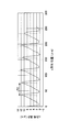
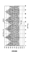
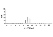
- FIG. 10 is a diagram showing a histogram (class width 4.0 ⁇ m) of the pitch in the z direction of the reflection slope according to Test Example 1.
- FIG. 11 is a diagram showing a histogram (class width 0.5 ⁇ m) of the pitch in the z direction of the reflection slope according to Test Example 1.
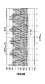
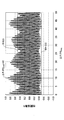
- FIG. 12 is a view showing the correlation coefficient R ( ⁇ P) of the undulation curve according to Test Example 1.
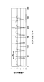
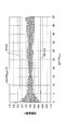
- FIG. 13 is a diagram showing the relationship between the output angle of background transmission light and the intensity according to Test Example 1.
- FIG. 14 is a diagram showing a histogram (class width 4.0 ⁇ m) of the pitch in the z direction of the reflection slope according to Test Example 2.
- FIG. 15 is a diagram showing a histogram (class width 0.5 ⁇ m) of the pitch in the z direction of the reflection slope according to Test Example 2.
- FIG. 16 is a view showing the correlation coefficient R ( ⁇ P) of the undulation curve according to Test Example 2.
- FIG. 17 is a diagram showing the relationship between the output angle of background transmission light and the intensity in Test Example 2.
- FIG. 18 is a diagram showing a histogram (class width 4.0 ⁇ m) of the pitch in the z direction of the reflection slope according to Test Example 3.
- FIG. 19 is a diagram showing a histogram (class width 0.5 ⁇ m) of the pitch in the z direction of the reflection slope according to Test Example 3.
- FIG. 20 is a view showing the correlation coefficient R ( ⁇ P) of the waviness curve according to Test Example 3.
- FIG. 21 is a diagram showing the relationship between the output angle of background transmission light and the intensity according to Test Example 3.
- FIG. 22 is a diagram showing a histogram (class width 4.0 ⁇ m) of the pitch in the z direction of the reflection slope according to Test Example 4.
- FIG. 23 is a diagram showing a histogram (class width 0.5 ⁇ m) of the pitch in the z direction of the reflection slope according to Test Example 4.
- FIG. 20 is a view showing the correlation coefficient R ( ⁇ P) of the waviness curve according to Test Example 3.
- FIG. 21 is a diagram showing the relationship between the output angle of background transmission light and the intensity according to Test Example 3.
- FIG. 22 is a diagram showing a histogram (class
- FIG. 24 is a view showing the correlation coefficient R ( ⁇ P) of the undulation curve according to Test Example 4.
- FIG. 25 is a view showing the relationship between the output angle of background transmission light and the intensity according to Test Example 4;
- FIG. 26 is a diagram showing a histogram (class width 4.0 ⁇ m) of the pitch in the z direction of the reflection slope according to Test Example 5.
- FIG. 27 is a diagram showing a histogram (class width 0.5 ⁇ m) of the pitch in the z direction of the reflection slope according to Test Example 5.
- FIG. 28 is a view showing the correlation coefficient R ( ⁇ P) of the waviness curve according to Test Example 5.
- FIG. 29 is a diagram showing the relationship between the output angle of background transmission light and the intensity in Test Example 5.
- FIG. 30 is a view showing an example of the positional relationship between the transparent screen of the image projection alignment plate, the projector, and the observer, as viewed from the front of the vehicle.
- FIG. 31 is a view showing another example of the positional relationship between the transparent screen of the image projection alignment plate, the projector, and the observer, as viewed from the front of the vehicle.
- FIG. 32 is a diagram showing still another example of the positional relationship between the transparent screen of the image projection alignment plate, the projector, and the observer, as viewed from the front of the vehicle.
- FIG. 33 is a flowchart illustrating a method of manufacturing a transparent screen according to an embodiment.
- FIG. 33 is a flowchart illustrating a method of manufacturing a transparent screen according to an embodiment.
- FIG. 34 is a view showing an example of the step of forming a plurality of slopes in a stripe on the first transparent layer.
- FIG. 35 is a view showing an example of the step of forming asperities on the slopes of the first transparent layer.
- FIG. 36 is a diagram showing an example of the step of forming a reflective layer.
- FIG. 37 is a view showing an example of the step of forming a second transparent layer. It is a figure which shows the video display system by a modification. It is a figure which shows the conventional transparent screen.
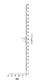
- FIG. 40 is a diagram showing the relationship between the z-direction position of the reflecting slope or slope and the inclination angle of the reflecting slope or slope according to one embodiment.
- FIG. 40 is a diagram showing the relationship between the z-direction position of the reflecting slope or slope and the inclination angle of the reflecting slope or slope according to one embodiment.
- FIG. 41 is a diagram showing a histogram (class width 4.0 ⁇ m) of the pitch in the z direction of the reflection slope according to Test Example 6.
- FIG. 42 is a diagram showing a histogram (class width 0.5 ⁇ m) of the pitch in the z direction of the reflection slope according to Test Example 6.
- FIG. 43 is a view showing the correlation coefficient R ( ⁇ P) of the undulation curve according to Test Example 6.
- FIG. 44 is a diagram showing the relationship between the output angle of background transmission light and the intensity in Test Example 6.
- FIG. 45 is a diagram showing a histogram (class width 4.0 ⁇ m) of the pitch in the z direction of the reflection slope according to Test Example 7.
- FIG. 41 is a diagram showing a histogram (class width 4.0 ⁇ m) of the pitch in the z direction of the reflection slope according to Test Example 6.
- FIG. 42 is a diagram showing a histogram (class width 0.5 ⁇ m) of the pitch in the z direction of the reflection slope according
- FIG. 46 is a diagram showing a histogram (class width 0.5 ⁇ m) of the pitch in the z direction of the reflection slope according to Test Example 7.
- FIG. 47 is a diagram showing the correlation coefficient R ( ⁇ P) of the undulation curve according to Test Example 7.
- FIG. 48 is a diagram showing the relationship between the outgoing angle of background transmission light and the intensity in Test Example 7;
- FIG. 49 is a diagram showing a histogram (class width 4.0 ⁇ m) of the pitch in the z direction of the reflection slope according to Test Example 8.
- FIG. 50 is a diagram showing a histogram (class width 0.5 ⁇ m) of the pitch in the z direction of the reflection slope according to Test Example 8.
- FIG. 51 is a diagram showing the correlation coefficient R ( ⁇ P) of the undulation curve according to Test Example 8.
- FIG. 52 is a diagram showing the relationship between the output angle of background transmission light and the intensity in Test Example 8;
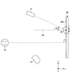
- FIG. 53 is an explanatory view schematically showing a positional relationship between a projector, an observer, and a transparent screen according to Test Examples 9 and 10.
- FIG. 54 is a view showing the arrangement of a luminance meter which measures the luminance at point A of the transparent screens of Test Examples 9 and 10.
- FIG. 55 is a view showing the arrangement of a luminance meter which measures the luminance at point B of the transparent screens of Test Examples 9 and 10.
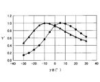
- FIG. 56 is a view showing the relationship between the luminance at point A of the transparent screens of Test Examples 9 and 10 and the inclination angle of a luminance meter that measures the luminance.
- FIG. 57 is a diagram showing the relationship between the luminance at point B of the transparent screens of Test Examples 9 and 10 and the inclination angle of a luminance meter that measures the luminance.
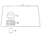
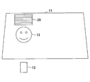
- FIG. 1 is a diagram illustrating a video display system according to an embodiment. In FIG. 1, the structure of the transparent screen 20 is shown enlarged.
- the image display system 10 includes an image projection alignment plate 11 capable of visually recognizing a background, and a projector 12 projecting an image on the image projection alignment plate 11.
- a general projector is used as the projector 12.
- the image projection aligning plate 11 displays an image projected from the front to the observer 13 in front, and makes the observer 13 in front visually recognize the background behind.
- the background behind may be visible if it is not projected on the video, and may or may not be visible on projecting the video.
- the image projection aligning plate 11 has a forward front surface 11a in contact with the atmosphere and a back surface 11b in contact with the atmosphere.
- a hot spot is generated.
- the hot spot is observed at a position in the regular reflection direction (for example, the position of the observer 14 indicated by a broken line) and is not observed at other positions (for example, the position of the observer 13 indicated by a solid line).
- the image projection aligning plate 11 may be either a flat plate or a curved plate.
- the curved plate may be any of those having a convex shape toward the observer 13 and those having a concave shape toward the observer 13.
- the application of the image projection laminated board 11 is not particularly limited, but, for example, window plates of vehicles such as cars and trains, window plates of buildings, window plates of show windows, window plates of refrigerated showcases, window plates of vehicles, and The partition etc. which divide a room are mentioned.
- the image projection alignment plate 11 includes a transparent screen 20, a first transparent plate 21 provided on one side (eg, the rear side) of the transparent screen 20, and a second transparent provided on the opposite side (eg, the front side) of the transparent screen 20. And a plate 22.
- the transparent screen 20 displays an image projected from the front to the viewer 13 in the front, and makes the background in the rear be viewed by the viewer 13 in the front.
- the structure of the transparent screen 20 will be described later.
- a glass plate is used as the first transparent plate 21 and the second transparent plate 22.
- a laminated glass is obtained as the image projection laminating plate 11.
- the method for producing laminated glass has, for example, the following steps (1) to (3).
- a polymer in which the first glass plate 21, the first adhesive layer 23, the transparent screen 20, the second adhesive layer 24, and the second glass plate 22 are stacked in this order is placed inside the vacuum bag. Put in. The stacking order may be reversed.
- the vacuum bag While degassing the inside of the vacuum bag containing the polymer, the vacuum bag is pressurized and heated in an air furnace or the like.
- the polymer removed from the vacuum bag is pressurized and heated with an autoclave.
- the glass of the glass plate examples include soda lime glass, aluminosilicate glass, alkali-free glass, borosilicate glass and the like.
- the glass may be either untempered glass or tempered glass. Untempered glass is obtained by forming molten glass into a plate and annealing. The forming method may, for example, be a float method or a fusion method.
- the tempered glass may be either physically tempered glass or chemically tempered glass.
- Physically tempered glass is a glass surface strengthened by rapidly cooling a uniformly heated glass plate from a temperature near the softening point and generating a compressive stress on the glass surface by the temperature difference between the glass surface and the inside of the glass. .
- Chemically strengthened glass is one in which the glass surface is strengthened by generating compressive stress on the glass surface by an ion exchange method or the like.
- the glass plate may be either a flat plate or a curved plate.
- gravity forming, press forming or the like is used as bending for bending a flat plate into a curved plate.
- the glass surface may be strengthened by quenching the uniformly heated glass plate from a temperature near the softening point and generating a compressive stress on the glass surface by the temperature difference between the glass surface and the inside of the glass. Physically tempered glass is obtained. Chemically strengthened glass can be obtained by generating compressive stress on the glass surface by an ion exchange method or the like after bending.
- the plate thickness of a glass plate is not specifically limited, For example, they are 0.1 mm or more and 20 mm or less.
- a resin plate may be used as the first transparent plate 21 and the second transparent plate 22.
- one of the first transparent plate 21 and the second transparent plate 22 may be a glass plate, and the other may be a resin plate.
- the number of transparent plates included in the image projection alignment plate may be three or more.
- the first adhesive layer 23 bonds the first transparent plate 21 and the transparent screen 20. Further, the second adhesive layer 24 bonds the second transparent plate 22 and the transparent screen 20.
- the thickness of each of the first adhesive layer 23 and the second adhesive layer 24 is not limited, but is, for example, 0.01 mm or more and 1.5 mm or less, preferably 0.3 mm or more and 0.8 mm or less.
- the first adhesive layer 23 and the second adhesive layer 24 may be formed of different materials, but are preferably formed of the same material.
- the first adhesive layer 23 and the second adhesive layer 24 are formed of, for example, a thermoplastic resin, a thermosetting resin, or an ultraviolet curable resin, and preferably a vinyl polymer, an ethylene-vinyl monomer copolymer, or the like. It is formed of one or more selected from a combination, a styrenic copolymer, a cycloolefin copolymer, a polyurethane resin, a urethane acrylate resin, a fluorine resin and an acrylic resin.
- thermoplastic resin polyvinyl butyral resin (PVB) and ethylene-vinyl acetate copolymer resin (EVA) are typical.
- thermosetting resin urethane acrylate resin is typical.
- adhesion is performed by heat treatment.
- an ultraviolet curable resin adhesion is performed by ultraviolet irradiation.
- the urethane acrylate resin can also be UV cured.
- the transparent screen 20 displays an image projected from the front to the viewer 13 in the front, and makes the background in the rear be viewed by the viewer 13 in the front. Sufficient transparency is obtained as the haze (Haze) value of the transparent screen 20 is 10% or less, and a background can be visually recognized favorably.
- the haze (Haze) value of the transparent screen 20 is 0% or more.
- the haze value of the glass plate used as the first transparent plate 21 or the second transparent plate 22 is usually 1% or less.
- the haze value is measured in accordance with Japanese Industrial Standard (JIS K7136), and among transmitted light transmitted in the thickness direction of the test plate to be measured, transmitted light deviated from incident light by 2.5 ° or more by forward scattering. It is determined as a percentage of As a light source used for measurement of haze value, D65 light source as described in Japanese Industrial Standard (JIS Z8720: 2012) is used.
- the transparent screen 20 may not be flexible, but may be flexible so that it can be deformed into various shapes.
- FIG. 2 shows a transparent screen according to one embodiment.
- the transparent screen 20 has a base sheet 31, a first transparent layer 32, a reflective layer 34, a second transparent layer 35, a protective sheet 36, and the like in this order from the rear side to the front side.
- the substrate sheet 31 may be either a transparent glass sheet or a transparent resin sheet, but is preferably a transparent resin sheet from the viewpoint of flexibility.
- the transparent resin sheet is formed of, for example, polycarbonate, PET, PEN, cycloolefin polymer, or polyester.
- the first transparent layer 32 is formed on the surface of the base sheet 31 and has irregularities on the surface opposite to the base sheet 31.
- the first transparent layer 32 is formed of, for example, a transparent resin.
- the resin may be any of a photocurable resin, a thermoplastic resin, and a thermosetting resin, and is formed by, for example, an imprint method.
- the first transparent layer 32 may be formed in a sawtooth shape in cross section.
- the reflective layer 34 is formed in a zigzag shape along the unevenness of the surface of the first transparent layer 32.
- the reflective layer 34 has unevenness on its front surface, and diffuses and reflects light of the image projected from the front to display the image.
- the reflective layer 34 also allows the background to be viewed by transmitting part of the light from the rear to the front.
- the irregularities are preferably irregular irregularities.
- the reflective layer 34 may be formed of a material that reflects light, for example, a metal such as aluminum or silver, a metal oxide, or a metal nitride.
- the reflective layer 34 may have either a single layer structure or a multilayer structure, and may include at least one of a metal layer and a dielectric layer.
- a method of forming the reflective layer 34 for example, a vacuum evaporation method or a sputtering method is used.
- the reflective layer 34 may include a dielectric multilayer film.
- the dielectric multilayer film can be formed by a method of laminating a plurality of dielectrics having different refractive indexes.
- the high refractive index dielectric include Si 3 N 4 , AlN, NbN, SnO 2 , ZnO, SnZnO, Al 2 O 3 , MoO, NbO, TiO 2 and ZrO 2 .
- Dielectrics having a lower refractive index than dielectrics having a high refractive index include, for example, SiO 2 , MgF 2 , and AlF 3 .
- the second transparent layer 35 fills the irregularities of the reflective layer 34.
- the second transparent layer 35 may be formed of a transparent resin as in the case of the first transparent layer 32, and is preferably formed of a resin having a refractive index substantially the same as that of the first transparent layer 32.
- the protective sheet 36 may be formed in the same manner as the base sheet 31, and is preferably formed of the same material as the base sheet 31.
- the base sheet 31 and the protective sheet 36 may have any configuration, and the transparent screen 20 may not have at least one of the base sheet 31 and the protective sheet 36.
- the first transparent layer 32 is formed in a sawtooth shape in cross section.
- the first transparent layer 32 has a plurality of slopes 42 which are inclined with respect to the reference surface 41 when the surface 41 on the opposite side to the reflective layer 34 of the first transparent layer 32 is the reference surface 41.
- the plurality of slopes 42 are formed in stripes when viewed from the normal direction of the reference surface 41. The streaks may be straight or curved.
- the normal direction of the reference surface 41 is the x direction
- the extension direction of each slope 42 is the y direction
- x direction The direction perpendicular to the y direction and in which the plurality of slopes 42 are arranged is also referred to as the z direction.
- the x direction is a first direction
- the y direction is a second direction
- the z direction is a third direction.
- the inclination angle ⁇ 1 ( ⁇ 1 is larger than -90 ° and smaller than 90 °) is watched Plus in the direction of rotation, minus in the counterclockwise direction. That the inclination angle ⁇ 1 of the slope 42 is 0 ° means that the slope 42 is parallel to the reference surface 41.
- the magnitude of the inclination angle ⁇ 1 is represented by “ ⁇ 1”.
- the inclination angle ⁇ 1 of the slope 42 is set based on the positional relationship between the projector 12, the observer 13, and the transparent screen 20, the refractive index of the transparent screen 20, and the like.
- the refractive index of the transparent screen 20 is taken into consideration because the incident light IL and the reflected light RL are refracted at the boundary between the transparent screen 20 and the atmosphere.
- the inclination angle ⁇ 1 of the slope 42 is set such that a hot spot is not observed and the entire image looks bright when the observer 13 standing at a preset position observes the image.
- the inclination angle ⁇ 1 of the slope 42 is, for example, -42 ° or more and 42 ° or less, preferably -30 ° or more and 30 ° or less, and more preferably -25 ° or more and 25 ° or less.
- the transparent screen 20 is used as a front window of a car and is inclined to the viewer 13
- the inclination angle ⁇ 1 of the slope 42 is -24 ° or more 18 ° or less, preferably ⁇ 20 ° or more and 15 ° or less, more preferably ⁇ 16 ° or more and 12 ° or less
- the slope 42 may be ⁇ 27 ° or more and 30 ° or less, preferably ⁇ 23 ° or more and 25 ° or less, and more preferably ⁇ 18 ° or more and 19 ° or less.
- the inclination angle ⁇ 1 of the slope 42 is 4 ° or more 32 It is sufficient if it is not more than 5 °, preferably not less than 5 ° and not more than 28 °, more preferably not less than 6 ° and not more than 24 °.
- the image projection area is measured for each slope 42 as it goes from one end (for example, lower end) in the z direction to the other end (for example, upper end) in the z direction.
- the plurality of slopes 42 are formed such that the inclination angle ⁇ 1 of the slope 42 decreases stepwise or continuously.
- the inclination angle ⁇ 1 (negative value in FIG. 1) of the uppermost slope 42 in FIG. 1 is smaller than the inclination angle ⁇ 1 (negative value in FIG. 1) of the lowermost slope 42 in FIG.
- the inclination angle ⁇ 1 of the slope 42 may change only in the negative range, may change only in the positive range, or may change over both the negative range and the positive range.
- ⁇ 1 decreases stepwise or continuously from the lower end to the upper end
- ⁇ 1 may decrease stepwise or continuously from the upper end to the lower end.
- the positions of the projector 12 and the observer 13 determine ⁇ 1.
- the relationship between the z-direction position of the slope 42 and the inclination angle ⁇ 1 of the slope 42 is shown in FIG.
- the first point 41P1, the second point 41P2, and the third point 41P3 are located on the reference surface 41.
- the first point 41P1 is an intermediate point between the second point 41P2 and the third point 41P3 separated by 100 mm in the z direction, and is arbitrarily set.
- the second point 41P2 is a point separated by 50 mm from the first point 41P1 to one end side in the z direction (for example, the negative side in the z direction).
- the third point 41P3 is a point separated by 50 mm from the first point 41P1 on the other end side in the z direction (for example, the positive side in the z direction).
- the average value of the inclination angles ⁇ 1 of the five consecutive slopes 42 closest to the first point 41P1 is ⁇ 1A (a negative value in FIG. 40).
- the average value of the inclination angles ⁇ 1 of the five consecutive slopes 42 closest to the second point 41P2 is ⁇ 1B (a negative value in FIG. 40).
- the average value of the inclination angles ⁇ 1 of the five consecutive slopes 42 closest to the third point 41P3 is ⁇ 1C (a negative value in FIG. 40).
- ⁇ 1A, ⁇ 1B, and ⁇ 1C satisfy the expression “ ⁇ 1B> ⁇ 1A> ⁇ 1C”.
- the pitch P1 in the z direction of the slope 42 is, for example, 15 ⁇ m or more, and preferably 20 ⁇ m or more. If the pitch P1 in the z direction of the slope 42 is 15 ⁇ m or more, the emission angle of diffracted light with the strongest intensity among the diffracted light described later can be reduced, and recognition of a multiple image of an image as a ghost can be suppressed. Moreover, the pitch P1 in the z direction of the slope 42 is 300 ⁇ m or less. If the pitch P1 in the z direction of the slope 42 is 300 ⁇ m or less, the stripes of the slope 42 are narrow enough to be invisible to the observer 13.
- the pitch P1 in the z-direction of the slope 42 may have irregularity similar to the pitch P2 in the z-direction of the reflection slope 45 described later. Thereby, although the details will be described later, it is possible to suppress the diffraction of light transmitted from the rear side to the front side of the transparent screen 20, and it is possible to suppress that the background is viewed multiple times.
- a step surface 43 connecting the plurality of adjacent slopes 42 is formed between the plurality of adjacent slopes 42.
- the step surface 43 is perpendicular to the reference surface 41 in FIG. 2 but may be oblique.
- a parallel surface parallel to the reference surface 41 may be formed between the plurality of adjacent slopes 42.
- the transparent screen 20 further includes a concavo-convex layer 33 which forms asperities on the slopes 42 of the first transparent layer 32 between the first transparent layer 32 and the reflective layer 34.
- the uneven layer 33 includes particles 37 and a matrix 38.
- the particles 37 include at least one of inorganic particles and organic particles.
- the material of the inorganic particles include silicon dioxide, partial nitride of silicon dioxide, titanium oxide, aluminum oxide, mixed crystal material of silicon dioxide and aluminum oxide, zirconium oxide, zinc oxide and the like.
- the material of the organic particles include polystyrene resin, acrylic resin, polyurethane resin and the like.
- the matrix 38 contains at least one of an inorganic material and an organic material.
- an inorganic material silicon dioxide, titanium oxide, zirconia oxide, sodium silicate and the like can be mentioned.
- the organic material include polyvinyl alcohol resin, polyvinyl butyral resin, epoxy resin, acrylic resin, polyester resin, polycarbonate resin, melamine resin, polyurethane resin, urethane acrylate resin, silicone resin and the like.
- the organic material may be any of a thermosetting resin, a photocurable resin, and a thermoplastic resin.
- the absolute value of the difference in refractive index between the particles 37 and the matrix 38 is preferably as small as possible, and is, for example, 0.1 or less, preferably 0.05 or less, more preferably 0.02 or less.
- the absolute value of the difference in refractive index between the particles 37 and the first transparent layer 32 is preferably as small as possible, and is, for example, 0.1 or less, preferably 0.05 or less, and more preferably 0.02 or less.
- the absolute value of the difference in refractive index between the matrix 38 and the first transparent layer 32 is preferably as small as possible, and is, for example, 0.1 or less, preferably 0.05 or less, more preferably 0.02 or less.
- the proportion of the particles 37 in the uneven layer 33 is, for example, 1% or more and 80% or less, preferably 5% or more and 60% or less.
- the concavo-convex layer 33 has concavities and convexities on the surface in contact with the reflective layer 34, and has a structure in which the convex parts 33a and the concave parts 33b are alternately arranged in a cross section perpendicular to the y direction.
- the regularity of the concavo-convex shape of the concavo-convex layer 33 it is easy to obtain regularity if the variation of the particle diameter of the particles 37 is reduced, and if the variation of the particle diameter of the particles 37 is enlarged, the regularity is broken to make random irregularities. it can. Also, by making the total volume of the particles 37 smaller than the volume of the matrix 38, random asperity can be obtained. In particular, by setting the volume of the particles 37 to 100% or less of the volume of the matrix 38, regularity can be reduced.
- the light scattering direction can be easily aligned, so that the luminance can be further increased.
- “surface roughness Ra” refers to the arithmetic average roughness described in Japanese Industrial Standard (JIS B0601).
- JIS B0601 Japanese Industrial Standard
- the surface roughness Ra of the uneven layer 33 is measured in the y direction.
- the surface roughness Ra of the uneven layer 33 is measured not in the z direction but in the y direction so that noise is not generated due to the first transparent layer 32 being formed in a sawtooth shape in a cross section perpendicular to the y direction. Do.
- the reflective layer 34 has a thickness of, for example, 5 nm or more and 5000 nm or less, and is formed along the unevenness of the uneven layer 33. Therefore, the reflective layer 34 has a plurality of reflective slopes 45 that are inclined with respect to the reference surface 41 and reflect the light of the projected image. A step surface 46 or the like is formed between the adjacent reflection slopes 45. The plurality of reflective slopes 45 are formed in stripes when viewed from the normal direction of the reference surface 41. The streaks may be straight or curved.
- each reflective slope 45 With reference to FIG. 3 etc., a dimension, a shape, etc. of each reflective slope 45 are demonstrated.
- the y direction is a direction perpendicular to the x direction, which is the extending direction of each of the reflection slopes 45.
- the z direction is a direction perpendicular to the x direction and the y direction, and is a direction in which a plurality of reflective slopes 45 are arranged.
- the x direction is a first direction
- the y direction is a second direction
- the z direction is a third direction.
- FIG. 3 is a diagram illustrating a path of light of an image from a projector according to an embodiment until it is reflected by a reflection slope and reaches an observer.
- FIG. 3 in a cross section perpendicular to the y direction, light of an image projected from the projector 12 is incident at the first incident angle ⁇ on the front surface 20 a of the transparent screen 20 and at the first refraction angle ⁇ ′. Refraction. Then, the light of the image is reflected by the reflection slope 45 inclined at the inclination angle ⁇ 2 with respect to the reference surface 41. Thereafter, the light of the image is incident on the front surface 20 a of the transparent screen 20 at the second incident angle ⁇ ′ and is refracted at the second refraction angle ⁇ , and then enters the eyes of the observer 13.
- the first incident angle ⁇ representing the position of the projector 12 and the second refraction angle ⁇ representing the position of the viewer 13 are appropriately set according to the application of the transparent screen 20, and for each reflecting slope 45 It may be set.
- the first incident angle ⁇ and the second refraction angle ⁇ may be collectively set for each of the plurality of continuous reflecting slopes 45.
- the first refraction angle ⁇ ′ and the second incidence angle ⁇ ′ are set using Snell's law equation.
- the first refraction angle ⁇ ′ is the relative refractive index n of the material (the second transparent layer 35 in FIG. 3) existing immediately before the reflection slope 45 and the first incident angle ⁇ .
- Sin ( ⁇ ) / sin ( ⁇ ′) n.
- the refractive index of a material present between the second transparent layer 35 and the atmosphere (for example, the second transparent plate 22 shown in FIG. 1) Can be ignored. Even when the second transparent plate 22 is present, the first refractive angle ⁇ ′ and the second incident angle ⁇ ′ can be obtained according to the Snell's law equation, assuming that the second transparent layer 35 is in contact with the atmosphere. Good. The value to be determined does not change depending on the presence or absence of the second transparent plate 22.
- the first incident angle ⁇ , the first refraction angle ⁇ ′, the second incident angle ⁇ are respectively positive in the clockwise direction and negative in the counterclockwise direction.
- the first incident angle ⁇ , the first refraction angle ⁇ ′, the second incidence angle ⁇ ′, the second refraction angle ⁇ and the inclination angle ⁇ 2 are respectively larger than ⁇ 90 ° and smaller than 90 °. That the inclination angle ⁇ 2 of the reflection slope 45 is 0 ° means that the reflection slope 45 is parallel to the reference plane 41.
- the first incident angle ⁇ , the first refraction angle ⁇ ′ and the inclination angle ⁇ 2 are negative, their sizes are represented by “ ⁇ ”, “ ⁇ ′” and “ ⁇ 2”. .
- the inclination angle ⁇ 2 of the reflection slope 45 is set based on the positional relationship between the projector 12, the observer 13, and the transparent screen 20, the refractive index of the transparent screen 20, and the like.
- the refractive index of the transparent screen 20 is taken into consideration because the incident light IL and the reflected light RL are refracted at the boundary between the transparent screen 20 and the atmosphere.
- the inclination angle ⁇ 2 of the reflection slope 45 is set such that when the observer 13 standing at a preset position observes an image, a hot spot is not observed and the entire image looks bright.
- the inclination angle ⁇ 2 of the reflection slope 45 and the inclination angle ⁇ 1 of the slope 42 are substantially the same between the reflection slope 45 and the slope 42 having the same z-direction position.
- the inclination angle ⁇ 2 of the reflection slope 45 is, for example, ⁇ 42 ° or more and 42 ° or less, preferably ⁇ 30 ° or more and 30 ° or less, and more preferably ⁇ 25 ° or more and 25 ° or less.
- the inclination angle ⁇ 2 of the reflecting slope 45 is -24 ° 18 ° or less, preferably ⁇ 20 ° or more and 15 ° or less, more preferably ⁇ 16 ° or more and 12 ° or less, and (2) a reflection slope when the short focus projector is used as the projector 12
- the inclination angle ⁇ 2 of 45 may be ⁇ 27 ° or more and 30 ° or less, preferably ⁇ 23 ° or more and 25 ° or less, and more preferably ⁇ 18 ° or more and 19 ° or less.
- the inclination angle ⁇ 2 of the reflecting slope 45 is 4 ° or more
- the angle may be 32 ° or less, preferably 5 ° or more and 28 ° or less, and more preferably 6 ° or more and 24 ° or less.
- the plurality of reflection slopes 45 are formed such that the inclination angle ⁇ 2 of the reflection slope 45 measured for each slope 45 decreases stepwise or continuously.
- the inclination angle ⁇ 2 (negative value in FIG. 1) of the uppermost reflection slope 45 in FIG. 1 is smaller than the inclination angle ⁇ 2 (negative value in FIG. 1) of the lowermost reflection slope 45 in FIG.
- the light of the highest intensity among the diffusely reflected light can be directed to the observer 13 by the plurality of reflection slopes 45 having different z-direction positions. Therefore, the difference between the brightness of the central portion of the image and the brightness of the outer portion of the image can be reduced, and a direction in which the entire image can be observed brightly can be created.
- the inclination angle ⁇ 2 of the reflection slope 45 may change only in the negative range, may change only in the positive range, or may change over both the negative range and the positive range. In FIG. 1, ⁇ 2 decreases stepwise or continuously from the lower end to the upper end, but ⁇ 2 may decrease stepwise or continuously from the upper end to the lower end.
- the positions of the projector 12 and the observer 13 determine ⁇ 2.
- the relationship between the z-direction position of the reflecting slope 45 and the inclination angle ⁇ 2 of the reflecting slope 45 is shown in FIG.
- the first point 41P1, the second point 41P2, and the third point 41P3 are located on the reference surface 41.
- the first point 41P1 is an intermediate point between the second point 41P2 and the third point 41P3 separated by 100 mm in the z direction, and is arbitrarily set.
- the second point 41P2 is a point separated by 50 mm from the first point 41P1 to one end side in the z direction (for example, the negative side in the z direction).
- the third point 41P3 is a point separated by 50 mm from the first point 41P1 on the other end side in the z direction (for example, the positive side in the z direction).
- the average value of the inclination angles ⁇ 2 of the five successive reflection slopes 45 closest to the first point 41P1 is ⁇ 2A (a negative value in FIG. 40).
- the average value of the inclination angles ⁇ 2 of the five consecutive reflection slopes 45 closest to the second point 41P2 is ⁇ 2B (a negative value in FIG. 40).
- the average value of the inclination angles ⁇ 2 of the five successive reflection slopes 45 closest to the third point 41P3 is ⁇ 2C (a negative value in FIG. 40).
- ⁇ 2A, ⁇ 2B, and ⁇ 2C satisfy the formula “ ⁇ 2B> ⁇ 2A> ⁇ 2C”.
- the light of the highest intensity among the diffusely reflected light can be directed to the observer 13 by the plurality of reflection slopes 45 having different z-direction positions. Therefore, the difference between the brightness of the central portion of the image and the brightness of the outer portion of the image can be reduced, and a direction in which the entire image can be observed brightly can be created.
- a plurality of reflective slopes 45 may be formed in at least a part of the image projection area with normals 45n approaching each other as it goes forward from the transparent screen 20.
- the light of the highest intensity among the diffusely reflected light can be directed to the observer 13 by the plurality of reflection slopes 45 having different z-direction positions. Therefore, the difference between the brightness of the central portion of the image and the brightness of the outer portion of the image can be reduced, and a direction in which the entire image can be observed brightly can be created.
- the direction of the normal 45n of the reflection slope 45 can be expressed by ⁇ 2 + 90 ° or ⁇ 2-90 °.
- the method of measuring the inclination angle ⁇ 2 will be described later together with the method of measuring the pitch P2.
- the pitch P2 of the reflective slope 45 in the z direction is, for example, 15 ⁇ m or more, and preferably 20 ⁇ m or more. If the pitch P2 in the z direction of the reflection slope 45 is 15 ⁇ m or more, the emission angle of the diffracted light having the strongest intensity among the diffracted lights described later can be reduced, and recognition of the multiplexed image of the image as a ghost can be suppressed. Moreover, the pitch P2 in the z direction of the reflective slope 45 is 300 ⁇ m or less. If the pitch P2 in the z direction of the reflective slope 45 is 300 ⁇ m or less, the stripes of the reflective slope 45 are narrow enough to be invisible to the observer 13.
- the pitch P2 of the reflection slope 45 in the z direction and the pitch P1 of the slope 42 in the z direction are substantially the same between the reflection slope 45 and the slope 42 having the same z-direction position.
- the method of measuring the pitch P2 will be described later.
- step surfaces 46 connecting the plurality of adjacent reflecting slopes 45 are formed between the plurality of adjacent reflecting slopes 45.
- the step surface 46 is perpendicular to the reference surface 41 in FIG. 2, it may be oblique.
- a parallel surface parallel to the reference surface 41 may be formed between the plurality of adjacent reflecting slopes 45.
- the reflective slope 45 has irregularities, and has a structure in which convex portions 45 a and concave portions 45 b are alternately arranged in a cross section perpendicular to the y direction.
- the unevenness of the reflective slope 45 may be regular or irregular, but preferably irregular.
- the surface roughness Ra of the reflective slope 45 is measured in the y direction.
- the surface roughness Ra of the reflective slope 45 is measured not in the z direction but in the y direction so that noise is not generated due to the first transparent layer 32 being formed in a sawtooth shape in a cross section perpendicular to the y direction. Do.
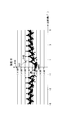
- FIG. 4 is a view showing a cross-sectional curve of a front surface (including a reflection slope, a step surface, and the like) of a reflection layer according to an embodiment.
- the horizontal axis represents the z-direction position
- the vertical axis represents the x-direction position.
- FIG. 5 is a diagram showing an undulation curve obtained by applying a short wavelength cut filter to the cross-sectional curve of FIG.
- FIG. 6 is a diagram showing the first derivative of the undulation curve of FIG.
- FIG. 7 is a diagram showing the second derivative of the undulation curve of FIG.
- dotted lines indicate the positions of the convex apexes of the reflection slope 45.
- the cross-sectional curve (see FIG. 4) of the front surface of the reflective layer 34 is measured by a commercially available laser microscope or the like.
- the cross-sectional curve is a cross section passing through the central point of the projection lens of the projector 12 and the central point of the eye of the observer 13 and is measured in a cross section perpendicular to the y direction.
- a short wavelength cut filter is applied to the cross-sectional curve shown in FIG. 4, wavelength components shorter than 10 ⁇ m are removed from the cross-sectional curve, and an undulation curve shown in FIG. 5 is obtained.
- the undulation curve shown in FIG. 5 is first-order differentiated to obtain a first-order derivative shown in FIG. 6, and the undulation curve shown in FIG. 5 is second-order differentiated to obtain a second-order derivative shown in FIG.
- the position where the first derivative becomes zero and the second derivative becomes negative is taken as the convex apex of the reflection slope 45.
- One pitch section is from the convex apex of one reflection slope 45 to the convex apex of the next reflection slope 45.
- the length in the z direction of one pitch section is the pitch P2 in the z direction of the reflective slope 45.
- the convex apex of the next one reflection slope 45 is set at a position separated from the convex apex of the one reflection slope 45 by a predetermined distance or more.
- the "predetermined distance” is the cutoff value (10 ⁇ m) of the short wavelength cut filter. Thereby, the noise of the minute unevenness formed on the reflective slope 45 can be removed.
- the surface roughness Ra of the reflection slope 45 is 10 ⁇ m or less as described above.
- the cutoff value of the short wavelength cut filter is not limited to 10 ⁇ m.
- the cutoff value of the short wavelength cut filter is the minimum at which the ratio (PV2 / PV1) of the PV value (PV2) of the inflection curve to the PV value (PV1) of the cross section curve is 0.5 or more in the range of 5 ⁇ m to 50 ⁇ m. Choose a value.
- the ratio (PV2 / PV1) decreases as the cutoff value increases.
- the PV value means the maximum height difference (the difference between Peak and Valley) in the x direction.
- the ratio (PV1 / P2) of the maximum height difference (PV1) in the x direction of the reflection slope 45 to the pitch (P2) in the z direction of the reflection slope 45 is 0.6 or less.
- PV1 / P2 is 0.6 or less, the absolute value of the inclination angle ⁇ 2 of most of the reflection slopes 45 can be 45 ° or less, forward scattering can be suppressed, and the haze can be reduced.
- the arithmetic mean P2 AVE of P2 is 40 ⁇ m
- the maximum P2 MAX of P2 is 52 ⁇ m
- the minimum P2 MIN of P2 is 28 ⁇ m
- PV1 is 13 ⁇ m
- PV1 / P2 is 0. It is 25-0.46.
- PV1 / P2 is preferably 0.01 or more.
- FIG. 8 is a histogram of tilt angles of cross-sectional curves in one pitch interval according to one embodiment.
- the horizontal axis is the inclination angle (°)
- the vertical axis is the frequency.
- the inclination angle of the cross-sectional curve is measured at 160 points (including the start point and the end point of one pitch section) dividing one pitch section at equal intervals.
- a histogram (see FIG. 8) of inclination angles of cross-sectional curves (see FIG. 4) in one pitch section is created.
- the class width is 2 °
- the class value is k (k is an even number between -90 and 90).
- the range of each class is k-1 ° or more and less than k + 1 °.
- the class value of the class having the largest frequency is set as the inclination angle ⁇ 2 of the reflection slope 45.
- the inclination angle ⁇ 2 of the reflection slope 45 is 18 °.
- the pitch P2 of the reflection slope 45 in the z direction and the inclination angle ⁇ 2 of the reflection slope 45 are measured.
- the z-direction position of light (hereinafter also referred to as “background transmission light”) that transmits the transparent screen 20 from the rear side to the front side is a background between the position where the z-direction passes the reflection slope 45 and the position where the step surface 46 passes. Since the distance of the transmitted light passing through the reflection layer 34 is different, the transmittance of the background transmitted light is different. Specifically, when passing through the step surface 46, the distance through which the background transmission light passes through the reflection layer 34 is longer than when passing through the reflection slope 45, and the transmittance of the background transmission light is low. Therefore, the transmittance of the background transmitted light changes according to the z-direction position.
- a plurality of reflective slopes 45 having irregular pitches P2 in the z direction may be formed.
- the satisfaction of both the following first condition and the following second condition means that the different pitches P2 are irregularly arranged.
- the pitch P2 is considered to be the same in the range of the error.
- P2 MAX is the maximum value of P2
- P2 MIN is the minimum value of P2.
- the maximum fluctuation rate of the pitch P2 is preferably 10% or more, more preferably 13% or more, and particularly preferably 15% or more.
- the first condition is that at least one pitch P2 of 95% or less or 105% or more of the arithmetic mean value P2 AVE is present.
- the first condition will be described with reference to FIG.
- FIG. 9 is a histogram of the pitch in the z direction of the reflective slope according to one embodiment.
- the pitch P2 of the reflection slopes 45 in the z direction is measured for each reflection slope 45.
- the arithmetic mean value P2 AVE of the measured pitch P2 is calculated.
- the ratio of the pitch P2 to the arithmetic mean value P2 AVE is calculated as a percentage (P2 / P2 AVE ⁇ 100). For calculation of this percentage (P2 / P2 AVE ⁇ 100), not a class value but an actual measurement value is used. In FIG. 9, P2 AVE is 83 ⁇ m.
- the first condition is that the error deviation rate (N1 / N2 ⁇ 100) is larger than zero.
- the error deviation rate is preferably 5% or more, more preferably 25% or more, and particularly preferably 50% or more.
- the second condition is that the absolute value of the correlation coefficient R ( ⁇ P) obtained by the following equation (1) is less than 0.5.
- the correlation coefficient R ( ⁇ P) is a value representing the consistency between the undulation curve x (z) (see FIG. 5) and the curve x (z + ⁇ P) obtained by shifting the undulation curve x (z) in the z direction by ⁇ P.
- ⁇ P is an arbitrary value of 10 ⁇ P2 AVE or more and 50 ⁇ P2 AVE or less.
- Table 1 summarizes the success or failure of the first condition and the success or failure of the second condition in Test Examples 1 to 8. Further, the error deviation rate and the maximum fluctuation rate of P2 in Test Examples 1 to 8 are summarized in Table 1.
- the relationship between the outgoing angle of the background transmitted light and the intensity is mainly determined by the pitch P2 in the z direction of the reflecting slope 45.
- the inclination angle ⁇ 2 of the reflecting slope 45 and PV1 / P2 hardly affect the relationship between the outgoing angle of the background transmitted light and the intensity.
- test Example 6 although the first condition is satisfied (see FIG. 41 (see FIG. 42 in detail)), the second condition is not satisfied (see FIG. 43).
- Test Example 7 the first condition is met (see FIG. 45 (see FIG. 46 in detail)), and the second condition is also met (see FIG. 47).
- Test Example 8 the first condition is met (see FIG. 49 (see FIG. 50 in detail)), and the second condition is also met (see FIG. 51).
- FIG. 10 is a diagram showing a histogram (class width 4.0 ⁇ m) of the pitch in the z direction of the reflection slope according to Test Example 1.
- FIG. 11 is a diagram showing a histogram (class width 0.5 ⁇ m) of the pitch in the z direction of the reflection slope according to Test Example 1.
- FIG. 12 is a view showing the correlation coefficient R ( ⁇ P) of the undulation curve according to Test Example 1.
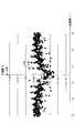
- FIG. 13 is a diagram showing the relationship between the output angle of background transmission light and the intensity according to Test Example 1. The intensity was measured at an emission angle of 0.014 °. In Test Example 1, the intensity I1 (see FIG.
- the diffracted light with the strongest intensity among the light diffracted by the repetitive structure of the reflection slope (hereinafter, also simply referred to as "diffracted light") and the diffracted light are adjacent. Since the intensity ratio (I1 / I2) to the intensity I2 (see FIG. 13) of the light at the measurement point was 7 or more (specifically, about 10 3 ), the diffracted light was visually recognized as a multiple image. In the test example 1, the intensity I0 of the exit angle is 0 ° of the light was highest intensity ratio of the intensity I1 of the intensity is strong diffracted light (I0 / II) is 10 5 or more.
- FIG. 14 is a diagram showing a histogram (class width 4.0 ⁇ m) of the pitch in the z direction of the reflection slope according to Test Example 2.
- FIG. 15 is a diagram showing a histogram (class width 0.5 ⁇ m) of the pitch in the z direction of the reflection slope according to Test Example 2.
- FIG. 16 is a view showing the correlation coefficient R ( ⁇ P) of the undulation curve according to Test Example 2.
- FIG. 17 is a diagram showing the relationship between the output angle of background transmission light and the intensity in Test Example 2. The intensity was measured at an emission angle of 0.014 °. In Test Example 2, the intensity ratio (I1) between the intensity I1 (see FIG. 17) of diffracted light with the highest intensity among the diffracted light and the intensity I2 (see FIG.
- the diffracted light was viewed as a multiple image.
- the intensity ratio (I0 / I1) between the intensity I0 of the light having an emission angle of 0 ° and the intensity I1 of the diffracted light having the highest intensity was 10 5 or more.
- FIG. 18 is a diagram showing a histogram (class width 4.0 ⁇ m) of the pitch in the z direction of the reflection slope according to Test Example 3.
- FIG. 19 is a diagram showing a histogram (class width 0.5 ⁇ m) of the pitch in the z direction of the reflection slope according to Test Example 3.
- FIG. 20 is a view showing the correlation coefficient R ( ⁇ P) of the waviness curve according to Test Example 3.
- FIG. 21 is a diagram showing the relationship between the output angle of background transmission light and the intensity according to Test Example 3. The intensity was measured at an emission angle of 0.014 °. In Test Example 3, the intensity ratio (I1) of the intensity I1 (see FIG.
- the intensity ratio (I0 / I1) between the intensity I0 of the light having an emission angle of 0 ° and the intensity I1 of the diffracted light having the highest intensity was 10 5 or more.
- FIG. 22 is a diagram showing a histogram (class width 4.0 ⁇ m) of the pitch in the z direction of the reflection slope according to Test Example 4.
- FIG. 23 is a diagram showing a histogram (class width 0.5 ⁇ m) of the pitch in the z direction of the reflection slope according to Test Example 4.
- FIG. 24 is a view showing the correlation coefficient R ( ⁇ P) of the undulation curve according to Test Example 4.
- FIG. 25 is a view showing the relationship between the output angle of background transmission light and the intensity according to Test Example 4; The intensity was measured at an emission angle of 0.014 °.
- the intensity ratio (I1) between the intensity I1 (see FIG. 25) of diffracted light with the highest intensity among the diffracted light and the intensity I2 see FIG.
- the intensity ratio (I0 / I1) between the intensity I0 of the light with an outgoing angle of 0 ° and the intensity I1 of the diffracted light with the highest intensity was 10 5 or more. Since the intensity ratio (I0 / I1) was 10 5 or more, even when the intensity ratio (I1 / I2) was less than 7, the background point light source was not visually recognized as a line.
- FIG. 26 is a diagram showing a histogram (class width 4.0 ⁇ m) of the pitch in the z direction of the reflection slope according to Test Example 5.
- FIG. 27 is a diagram showing a histogram (class width 0.5 ⁇ m) of the pitch in the z direction of the reflection slope according to Test Example 5.
- FIG. 28 is a view showing the correlation coefficient R ( ⁇ P) of the waviness curve according to Test Example 5.
- FIG. 29 is a diagram showing the relationship between the output angle of background transmission light and the intensity in Test Example 5. The intensity was measured at an emission angle of 0.014 °.
- the intensity ratio (I1) of the intensity I1 see FIG. 29) of the diffracted light with the highest intensity among the diffracted light and the intensity I2 (see FIG.
- the intensity ratio (I0 / I1) of the intensity I0 of light having an emission angle of 0 ° to the intensity I1 of diffracted light having the highest intensity is 10 5 or more (specifically, about 10 6 ). Met. Since the intensity ratio (I0 / I1) was 10 5 or more, even when the intensity ratio (I1 / I2) was less than 7, the background point light source was not visually recognized as a line.
- FIG. 41 is a diagram showing a histogram (class width 4.0 ⁇ m) of the pitch in the z direction of the reflection slope according to Test Example 6.
- FIG. 42 is a diagram showing a histogram (class width 0.5 ⁇ m) of the pitch in the z direction of the reflection slope according to Test Example 6.
- FIG. 43 is a view showing the correlation coefficient R ( ⁇ P) of the undulation curve according to Test Example 6.
- FIG. 44 is a diagram showing the relationship between the output angle of background transmission light and the intensity in Test Example 6. The intensity was measured at an emission angle of 0.014 °.
- the intensity ratio (I1) between the intensity I1 (see FIG. 44) of diffracted light with the highest intensity among the diffracted light and the intensity I2 see FIG.
- the intensity ratio (I0 / I1) of the intensity I0 of light having an emission angle of 0 ° to the intensity I1 of diffracted light having the highest intensity is 10 5 or more (specifically, about 10 6 ).
- FIG. 45 is a diagram showing a histogram (class width 4.0 ⁇ m) of the pitch in the z direction of the reflection slope according to Test Example 7.
- FIG. 46 is a diagram showing a histogram (class width 0.5 ⁇ m) of the pitch in the z direction of the reflection slope according to Test Example 7.
- FIG. 47 is a diagram showing the correlation coefficient R ( ⁇ P) of the undulation curve according to Test Example 7.
- FIG. 48 is a diagram showing the relationship between the outgoing angle of background transmission light and the intensity in Test Example 7; The intensity was measured at an emission angle of 0.014 °.
- the intensity ratio (I1) of the intensity I1 see FIG. 48
- the intensity I2 see FIG.
- the intensity ratio (I0 / I1) of the intensity I0 of the light having an emission angle of 0 ° to the intensity I1 of the diffracted light having the highest intensity is 10 5 or more (specifically, about 10 6 ). Met. Since the intensity ratio (I0 / I1) was 10 5 or more, even when the intensity ratio (I1 / I2) was less than 7, the background point light source was not visually recognized as a line.
- FIG. 49 is a diagram showing a histogram (class width 4.0 ⁇ m) of the pitch in the z direction of the reflection slope according to Test Example 8.
- FIG. 50 is a diagram showing a histogram (class width 0.5 ⁇ m) of the pitch in the z direction of the reflection slope according to Test Example 8.
- FIG. 51 is a diagram showing the correlation coefficient R ( ⁇ P) of the undulation curve according to Test Example 8.
- FIG. 52 is a diagram showing the relationship between the output angle of background transmission light and the intensity in Test Example 8; The intensity was measured at an emission angle of 0.014 °.
- the intensity ratio (I1) between the intensity I1 (see FIG. 52) of diffracted light with the highest intensity among the diffracted light and the intensity I2 see FIG.
- the intensity ratio (I0 / I1) of the intensity I0 of the light having an emission angle of 0 ° to the intensity I1 of the diffracted light having the highest intensity is 10 5 or more (specifically, about 10 6 ). Met. Since the intensity ratio (I0 / I1) was 10 5 or more, even when the intensity ratio (I1 / I2) was less than 7, the background point light source was not visually recognized as a line.
- Test Example 9 the inclination angle ⁇ 2 of the reflection slope 45 was continuously changed according to the z-direction position.
- the histogram of the pitch P2 of Test Example 9 was the same as the histogram of the pitch P2 of Test Example 4.
- Test Example 10 the inclination angle ⁇ 2 of the reflection slope 45 was maintained constant regardless of the position in the z direction.
- the histogram of the pitch P2 of Test Example 10 was the same as the histogram of the pitch P2 of Test Example 1.
- the luminance characteristic of the transparent screen 20 is mainly determined by the inclination angle ⁇ 2 of the reflection slope 45.
- the pitch P2 and PV1 / P2 in the z-direction of the reflection slope 45 hardly affect the luminance characteristics of the transparent screen 20.
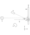
- FIG. 53 is an explanatory view schematically showing a positional relationship between a projector, an observer, and a transparent screen according to Test Examples 9 and 10.
- FIG. 53 the y-direction positions of the point A and the point B in the projector 12, the observer 13, and the transparent screen 20 are the same.
- the positions in the x direction and the z direction (unit: mm) of the point A and the point B in the projector 12, the observer 13, and the transparent screen 20 were as shown in Table 2.
- the x-direction position of the front surface 20a of the transparent screen 20 is “0” of the reference position of the x-direction position. Further, the z-direction position of the observer 13 is “0” of the reference position of the z-direction position.
- both “ ⁇ 1” and “ ⁇ 2” at point A of the transparent screen of Test Example 9 were 8 °.
- both “ ⁇ 1” and “ ⁇ 2” at point B of the transparent screen of Test Example 9 were 16 °.
- “ ⁇ 1” and “ ⁇ 2” at point A of the transparent screen of Test Example 10 were both 12 °.
- both “ ⁇ 1” and “ ⁇ 2” at point B of the transparent screen of Test Example 10 were 12 °.
- FIG. 54 is a view showing the arrangement of a luminance meter which measures the luminance at point A of the transparent screens of Test Examples 9 and 10.
- the luminance meter 51 was disposed on a plane including the point A and perpendicular to the y direction so as to be rotatable about the point A of the transparent screen 20.
- the inclination angle ⁇ A of the luminance meter 51 represents the inclination from the normal line 52 at the point A of the transparent screen 20.
- ⁇ A is 0, it means that the luminance meter 51 is disposed on the normal line 52 at the point A of the transparent screen 20.
- the fact that ⁇ A is positive means that the luminance meter 51 is disposed above the normal 52 in FIG.
- ⁇ A negative is that the luminance meter is below the normal 52 in FIG. 54. It means that 51 is arranged.
- a short focus projector was used as the projector 12.
- the inclination angle ⁇ A of the luminance meter 51 was 2 ° when the luminance meter 51 was disposed on a straight line connecting the point A and the observer 13.
- FIG. 55 is a view showing the arrangement of a luminance meter which measures the luminance at point B of the transparent screens of Test Examples 9 and 10.
- the luminance meter 51 is disposed on a plane that includes the point B and is perpendicular to the y direction so as to be rotatable about the point B of the transparent screen 20.
- the inclination angle ⁇ B of the luminance meter 51 represents the inclination from the normal line 53 at the point B of the transparent screen 20. That ⁇ B is 0 means that the luminance meter 51 is disposed on the normal line 53 at the point B of the transparent screen 20. Further, the fact that ⁇ B is positive means that the luminance meter 51 is disposed above the normal line 53 in FIG.
- ⁇ B is negative means that the luminance meter is below the normal line 53 in FIG. It means that 51 is arranged.
- a short focus projector was used as the projector 12.
- the inclination angle ⁇ B of the luminance meter 51 was ⁇ 9 ° when the luminance meter 51 was disposed on a straight line connecting the point B and the observer 13.
- FIG. 56 is a view showing the relationship between the luminance at point A of the transparent screens of Test Examples 9 and 10 and the inclination angle of a luminance meter that measures the luminance.
- the horizontal axis is the inclination angle ⁇ A of the luminance meter 51
- the vertical axis is the value Y ′ obtained by dividing the measurement value (cd / m 2 ) of the luminance meter 51 by its maximum value.
- the solid line shows the result of Test Example 9
- the dashed line shows the result of Test Example 10.
- the inclination angle ⁇ A of the luminance meter 51 at which the luminance at the point A of the transparent screen 20 of Test Example 9 is maximum was 0 °.
- the inclination angle ⁇ A of the luminance meter 51 at which the luminance at the point A of the transparent screen 20 of Test Example 10 is maximum was ⁇ 15 °.
- FIG. 57 is a diagram showing the relationship between the luminance at point B of the transparent screens of Test Examples 9 and 10 and the inclination angle of a luminance meter that measures the luminance.
- the horizontal axis is the inclination angle ⁇ B of the luminance meter 51
- the vertical axis is the value Y ′ obtained by dividing the measurement value (cd / m 2 ) of the luminance meter 51 by its maximum value.
- the solid line indicates the result of Test Example 9
- the dashed line indicates the result of Test Example 10.
- the inclination angle ⁇ B of the luminance meter 51 at which the luminance at the point B of the transparent screen 20 of Test Example 9 is maximum was ⁇ 10 °. Further, as is clear from FIG. 57, the inclination angle ⁇ B of the luminance meter 51 at which the luminance at the point B of the transparent screen 20 of Test Example 10 is maximum was 5 °.
- ⁇ A 0 is the inclination angle ⁇ A of the luminance meter 51 when the luminance meter 51 is disposed on the straight line connecting the point A and the observer 13.
- ⁇ A1 is the inclination angle ⁇ A of the luminance meter 51 when the luminance at the point A of the transparent screen 20 is maximum.
- ⁇ B 0 is an inclination angle ⁇ B of the luminance meter 51 when the luminance meter 51 is disposed on a straight line connecting the point B and the observer 13.
- ⁇ B1 is the inclination angle ⁇ B of the luminance meter 51 when the luminance at the point B of the transparent screen 20 is maximum.
- both of the difference between ⁇ A0 and ⁇ A1 and the difference between ⁇ B0 and ⁇ B1 can be made smaller than in the case of Test Example 10. Therefore, in the case of Test Example 9, the observer 13 can observe bright light with the same degree of brightness and brightness at both the point A and the point B as compared to the case of Test Example 10.
- the reflective layer 34 of the present embodiment is inclined with respect to the reference surface 41 and has a plurality of reflective slopes 45 that reflect the light of the projected image.
- the plurality of reflective slopes 45 are formed in stripes when viewed from the normal direction of the reference surface 41.
- Each reflection slope 45 has unevenness and displays an image. Therefore, the reflection slope 45 which displays an image is inclined with respect to the surface (the front surface 11a and the rear surface 11b) which produces a hot spot.
- the direction in which the bright image is observed is the regular reflection direction of the reflection slope 45
- the direction in which the hot spot is observed is the regular reflection direction of the front surface 11a or the like.
- the direction in which the hot spot is observed and the direction in which the bright image is observed can be separated, and the position where the bright image is observed without observing the hot spot (for example, the position of the observer 13 shown by the solid line in FIG. ) Can be produced.
- the plurality of reflection slopes 45 are formed such that the inclination angle ⁇ 2 of the reflection slope 45 measured for each slope 45 decreases stepwise or continuously.
- the light of the highest intensity among the diffusely reflected light can be directed to the observer 13 by the plurality of reflection slopes 45 having different z-direction positions. Therefore, the difference between the brightness of the central portion of the image and the brightness of the outer portion of the image can be reduced, and a direction in which the entire image can be observed brightly can be created.
- FIG. 30 is a view showing an example of the positional relationship between the transparent screen of the image projection alignment plate, the projector, and the observer, as viewed from the front of the vehicle.
- the image projection aligning plate 11 is attached to a window at the front of the vehicle.
- the transparent screen 20 is provided at the bottom of the window.
- the projector 12 is provided below the window.
- the eye of the observer 13 is located at the vertical center of the window.
- the plurality of reflecting slopes 45 may form horizontal stripes elongated in the horizontal direction.
- the observer 13 can observe a bright image at a position where the hot spot is not observed.
- FIG. 31 is a view showing another example of the positional relationship between the transparent screen of the image projection alignment plate, the projector, and the observer, as viewed from the front of the vehicle.
- the image projection aligning plate 11 is attached to a window at the front of the vehicle.
- the transparent screen 20 is provided at the top of the window.
- the projector 12 is provided below the window.
- the eye of the observer 13 is located at the vertical center of the window. Also in this case, as shown in FIG. 31, the plurality of reflecting slopes 45 may form horizontal stripes elongated in the horizontal direction.
- the observer 13 can observe a bright image at a position where the hot spot is not observed.
- FIG. 32 is a diagram showing still another example of the positional relationship between the transparent screen of the image projection alignment plate, the projector, and the observer, as viewed from the front of the vehicle.
- the image projection aligning plate 11 is attached to a window at the front of the vehicle.
- the transparent screen 20 is provided at the end in the vehicle width direction of the window.
- the projector 12 is provided below the window.
- the eye of the observer 13 is located at the vertical center of the window.
- the plurality of reflecting slopes 45 may form longitudinal stripes elongated in the vertical direction.
- the observer 13 can observe a bright image at a position where the hot spot is not observed.
- the projector 12 may be provided on the top of the window. Further, in FIGS. 30 to 32, the transparent screen 20 may be provided at the center of the window.
- the window provided with the transparent screen 20 may not be a front window, and may be, for example, a side window, a rear window, a roof window, or the like.
- the projector 12 may be provided around the window frame of the side window (for example, around the side door or handrail).
- the projector 12 is provided in the car.
- the transparent screen may be provided to the combiner rather than the window. A combiner is provided between the front window and the driver's seat. Also in these cases, there is an arrangement in which the observer 13 can observe a bright image at a position where the hot spot is not observed.
- FIG. 33 is a flowchart illustrating a method of manufacturing a transparent screen according to an embodiment.
- a step S103 of forming a reflective layer 34 in contact with the unevenness, and a step S104 of forming a second transparent layer 35 filling the unevenness of the reflective layer 34 are included.
- FIG. 34 is a view showing an example of the step of forming a plurality of slopes in a stripe on the first transparent layer.
- step S101 on the surface of the first transparent layer 32 opposite to the reference surface 41, a plurality of slopes 42 inclined with respect to the reference surface 41 are formed in stripes as viewed from the normal direction of the reference surface 41.
- a forming method thereof for example, an embossing method is used as shown in FIG.
- the embossing method is a method of transferring the concavo-convex pattern of the mold 60 to the first transparent layer 32.
- the embossing method includes an imprint method.
- the imprint method is a method in which the resin material to be the first transparent layer 32 is sandwiched between the mold 60 and the base sheet 31, the concavo-convex pattern of the mold 60 is transferred to the resin material, and the resin material is solidified.
- solidification includes curing.
- the method of solidification is suitably selected according to the kind of resin material.
- the type of resin material may be any of a photocurable resin, a thermoplastic resin, and a thermosetting resin.
- the photocurable resin is cured by light irradiation.
- the thermoplastic resin is melted by heating and solidified by cooling.
- the thermosetting resin changes from liquid to solid by heating.
- These resin materials may be applied to the base sheet 31 or may be applied to the mold 60 in a liquid state.
- the coating method is not particularly limited, and for example, a spray coating method, a spin coating method, a gravure coating method and the like are used.
- the cutting method may be used instead of the imprint method.
- the cutting method is a method of cutting the first transparent layer 32 with a cutting tool.
- the cutting tool may be general.
- FIG. 35 is a view showing an example of the step of forming asperities on the slopes of the first transparent layer.
- a method of forming the unevenness on the slope 42 for example, a film forming method in which a coating solution is applied to the slope 42 and the coating film of the coating solution is dried and solidified is used.
- the coating solution contains particles 37 and matrix 38, and may further contain a solvent for dissolving matrix 38.
- the method for applying the coating liquid is not particularly limited, and, for example, a spray coating method, a spin coating method, a gravure coating method, or the like is used.
- FIG. 36 is a diagram showing an example of the step of forming a reflective layer.
- a method of forming the reflective layer 34 for example, a vacuum evaporation method or a sputtering method is used.
- the reflective layer 34 is formed along the asperities of the asperity layer 33.
- FIG. 37 is a view showing an example of the step of forming a second transparent layer.
- the second transparent layer 35 is obtained by sandwiching the resin material to be the second transparent layer 35 between the reflective layer 34 and the protective sheet 36 and solidifying it.
- the transparent screen 20 of the present embodiment has a first transparent layer 32, an uneven layer 33, a reflective layer 34, and a second transparent layer 35 from the rear side to the front side.
- the transparent screen 20 may have the second transparent layer 35, the reflective layer 34, the concavo-convex layer 33, and the first transparent layer 32 in this order from the rear side to the front side.
- the reflective layer 34 the contact surface with the uneven layer 33 and the contact surface with the second transparent layer 35 have the same shape. Therefore, the reflective layer 34 may reflect the light of the projected image on either of the contact surface with the uneven layer 33 and the contact surface with the second transparent layer 35.
- FIG. 38 is a diagram showing a video display system according to a modification.
- the video display system 10A of this modification differs from the video display system 10 of the above embodiment in that it has a transparent screen 20A. The differences will be mainly described below.
- the uneven layer 33 shown in FIG. 2 and the like does not exist between the first transparent layer 32A and the reflective layer 34A, and the reflective layer 34A is in contact with the first transparent layer 32A. It differs from the transparent screen 20 of the embodiment.
- the transparent screen 20A, the first transparent plate 21 and the second transparent plate 22 constitute an image projection aligning plate 11A.
- the first transparent layer 32A has a plurality of slopes 42A inclined with respect to the reference surface 41A.
- the plurality of slopes 42A are formed in stripes when viewed from the normal direction of the reference surface 41A.
- Each slope 42A has unevenness.
- an etching method or an imprint method is used as a method of forming the unevenness on the slope 42A.
- the etching method is a method of forming the unevenness on the slope 42A by etching the slope 42A formed by the embossing method or the cutting method.
- the etching method may be either a physical etching method or a chemical etching method.
- Physical etching methods include blast methods.
- the blast method may be either a dry last method or a wet blast method.
- asperities are formed on the slope 42A by spraying particles on the slope 42A.
- particles for example, alumina particles, silicon carbide particles, zircon particles and the like are used.
- wet-blasting method a mixed fluid of particles and liquid is sprayed on the slope 42A to form asperities on the slope 42A.
- each slope 42A in a cross section perpendicular to the y direction, at least a part of the image projection area is measured for each slope 42A from one end (for example, lower end) in the z direction to the other end (for example, upper end) in the z direction.
- the plurality of slopes 42A are formed such that the slope angle ⁇ 1 of the slope 42A decreases gradually or continuously.
- the inclination angle ⁇ 1 (negative value) of the uppermost slope 42A in FIG. 38 is smaller than the inclination angle ⁇ 1 (negative value) of the lowermost slope 42A in FIG.
- the inclination angle ⁇ 1 of the slope 42A may change only in the negative range, may change only in the positive range, or may change over both the negative range and the positive range.
- the pitch P1 in the z direction of the slope 42A is, for example, 15 ⁇ m or more, and preferably 20 ⁇ m or more. If the pitch P1 in the z direction of the slope 42A is 15 ⁇ m or more, the emission angle of the diffracted light with the strongest intensity among the diffracted light can be reduced, and it is possible to suppress recognition of the multiplexed image of the image as a ghost. Moreover, the pitch P1 in the z direction of the slope 42A is 300 ⁇ m or less. If the pitch P1 in the z direction of the slope 42A is 300 ⁇ m or less, the stripes of the slope 42A are narrow enough to be invisible to the observer 13.
- the pitch P1 in the z-direction of the slope 42A may have irregularity similar to the pitch P2 in the z-direction of the reflection slope 45A described later. Thereby, diffraction of light transmitted from the rear side to the front side of the transparent screen 20 can be suppressed, and the background can be suppressed from being viewed in multiples.
- the reflective layer 34A is inclined with respect to the reference surface 41A and has a plurality of reflective slopes 45A that reflect the light of the projected image.
- the plurality of reflective slopes 45A are formed in stripes when viewed from the normal direction of the reference surface 41A.
- the reflective layer 34A has a thickness of, for example, 5 nm or more and 5000 nm or less, and is formed along the unevenness of the slope 42A. Therefore, each reflection slope 45A has unevenness. The unevenness of the reflective layer 34A is filled with the second transparent layer 35A.
- the plurality of reflecting slopes 45A are formed such that the inclination angle ⁇ 2 of the reflecting slope 45A decreases stepwise or continuously.
- the inclination angle ⁇ 2 (negative value) of the uppermost reflection slope 45A in FIG. 38 is smaller than the inclination angle ⁇ 2 (negative value) of the lowermost reflection slope 45A in FIG.
- the light of the highest intensity among the diffusely reflected light can be directed to the observer 13 by the plurality of reflection slopes 45A different in the z-direction position. Therefore, the difference between the brightness of the central portion of the image and the brightness of the outer portion of the image can be reduced, and a direction in which the entire image can be observed brightly can be created.
- the inclination angle ⁇ 2 of the reflection slope 45A may change only in the negative range, may change only in the positive range, or may change over both the negative range and the positive range.
- the highest intensity light of the light diffusely reflected by the reflection slope 45 can be directed to the viewer 13.
- the difference between the brightness of the central portion of the image and the brightness of the outer portion of the image can be reduced, and a direction in which the entire image can be observed brightly can be created.
- a plurality of reflective slopes 45A having normals 45An approaching each other as they move forward from the transparent screen 20A may be formed in at least a part of the image projection area. .
- the direction of the normal 45An of the reflection slope 45A can be represented by ⁇ 2 + 90 ° or ⁇ 2-90 °.
- the pitch P2 of the reflection slope 45A in the z direction is, for example, 15 ⁇ m or more, and preferably 20 ⁇ m or more. If the pitch P2 in the z direction of the reflection slope 45A is 15 ⁇ m or more, the emission angle of the diffracted light with the strongest intensity among the diffracted light can be reduced, and recognition of the multiplexed image of the image as a ghost can be suppressed. Moreover, the pitch P2 in the z direction of the reflective slope 45A is 300 ⁇ m or less. If the pitch P2 in the z direction of the reflection slope 45A is 300 ⁇ m or less, the stripes of the reflection slope 45A are narrow enough to be invisible to the observer 13. The pitch P2 of the reflection slope 45A in the z direction and the pitch P1 of the slope 42A in the z direction are substantially the same between the reflection slope 45A and the slope 42A having the same z-direction position.
- the pitch P2 of the reflective slope 45A in the z direction may have irregularity in order to suppress the change in the transmittance of the background transmitted light periodically in the z direction to suppress the diffraction of the background transmitted light. Thereby, the diffraction of the background transmitted light can be suppressed, and the background can be suppressed from being viewed multiple times.
- the reflection slope 45A that displays an image is inclined with respect to the surface (the front surface 11Aa or the rear surface 11Ab) that causes the hot spot.
- the direction in which the hot spot is observed and the direction in which the bright image is observed can be separated, and the position where the bright image is observed without observing the hot spot (for example, the position of the observer 13 shown in FIG. 38) Can be produced.
- the other end in the z direction from one end (for example, lower end) in the z direction A plurality of reflection slopes 45A are formed such that the inclination angle ⁇ 2 of the reflection slope 45A measured for each reflection slope 45A decreases stepwise or continuously toward (for example, the upper end).
- the light of the highest intensity among the diffusely reflected light can be directed to the observer 13 by the plurality of reflection slopes 45A different in the z-direction position. Therefore, the difference between the brightness of the central portion of the image and the brightness of the outer portion of the image can be reduced, and a direction in which the entire image can be observed brightly can be created.
- a resin layer is used as the first transparent layers 32 and 32A, but a glass layer may be used.
- a method of forming a plurality of slopes in a stripe on the glass layer for example, an embossing method is used.
- the embossing method is a method of transferring a concavo-convex pattern of a mold to a glass layer softened at a high temperature.
- the first transparent plate 21 may be used as the first transparent layers 32 and 32A.
- bending and embossing may be performed simultaneously by press forming.
- the uneven layer 33 and the reflective layer 34 are formed on the first transparent plate 21.
- the reflective layer 34A is formed on the first transparent plate 21.
- the second adhesive layer 24 may be used as the second transparent layer 35, 35A, and the second transparent plate 22 may be used instead of the protective sheet 36.
- the step of forming the plurality of slopes 42 in the form of stripes and the step of forming asperities on the slopes 42 are performed in this order, but may be performed simultaneously.
- the embossing method it can be performed simultaneously by roughening the uneven pattern surface of the mold 60 in advance by the etching method.
- the image projection alignment plates 11 and 11A may further have a functional layer (not shown).
- the functional layer include a light reflection preventing layer that reduces reflection of light, a light attenuation layer that attenuates part of light, and an infrared shielding layer that suppresses transmission of infrared light.
- examples of the functional layer include functional layers such as a vibration layer which vibrates by applying a voltage and which functions as a speaker, and a sound insulation layer which suppresses transmission of sound.
- the number of functional layers and the position of the functional layers are not particularly limited.
Landscapes
- Physics & Mathematics (AREA)
- General Physics & Mathematics (AREA)
- Optics & Photonics (AREA)
- Engineering & Computer Science (AREA)
- Manufacturing & Machinery (AREA)
- Chemical & Material Sciences (AREA)
- Combustion & Propulsion (AREA)
- Transportation (AREA)
- Mechanical Engineering (AREA)
- Overhead Projectors And Projection Screens (AREA)
- Optical Elements Other Than Lenses (AREA)
- Projection Apparatus (AREA)
Priority Applications (4)
| Application Number | Priority Date | Filing Date | Title |
|---|---|---|---|
| JP2019551085A JP7243633B2 (ja) | 2017-10-24 | 2018-10-18 | 透明スクリーン、映像投影合わせ板、映像表示システム、および透明スクリーンの製造方法 |
| CN201880067891.9A CN111247483B (zh) | 2017-10-24 | 2018-10-18 | 透明屏幕、影像投影层合板、影像显示系统、及透明屏幕的制造方法 |
| DE112018004988.4T DE112018004988T5 (de) | 2017-10-24 | 2018-10-18 | Transparenter bildschirm, laminierte bildprojektionsplatte, bildanzeigesystem und verfahren zur herstellung eines transparenten bildschirms |
| US16/837,022 US11106125B2 (en) | 2017-10-24 | 2020-04-01 | Transparent screen, image projection laminated plate, image display system, and method for producing transparent screen |
Applications Claiming Priority (2)
| Application Number | Priority Date | Filing Date | Title |
|---|---|---|---|
| JP2017205634 | 2017-10-24 | ||
| JP2017-205634 | 2017-10-24 |
Related Child Applications (1)
| Application Number | Title | Priority Date | Filing Date |
|---|---|---|---|
| US16/837,022 Continuation US11106125B2 (en) | 2017-10-24 | 2020-04-01 | Transparent screen, image projection laminated plate, image display system, and method for producing transparent screen |
Publications (1)
| Publication Number | Publication Date |
|---|---|
| WO2019082798A1 true WO2019082798A1 (ja) | 2019-05-02 |
Family
ID=66247475
Family Applications (1)
| Application Number | Title | Priority Date | Filing Date |
|---|---|---|---|
| PCT/JP2018/038890 Ceased WO2019082798A1 (ja) | 2017-10-24 | 2018-10-18 | 透明スクリーン、映像投影合わせ板、映像表示システム、および透明スクリーンの製造方法 |
Country Status (5)
| Country | Link |
|---|---|
| US (1) | US11106125B2 (https=) |
| JP (1) | JP7243633B2 (https=) |
| CN (1) | CN111247483B (https=) |
| DE (1) | DE112018004988T5 (https=) |
| WO (1) | WO2019082798A1 (https=) |
Cited By (3)
| Publication number | Priority date | Publication date | Assignee | Title |
|---|---|---|---|---|
| JP2022144381A (ja) * | 2021-03-19 | 2022-10-03 | セイコーエプソン株式会社 | 照明装置およびプロジェクター |
| JP2024519708A (ja) * | 2021-05-31 | 2024-05-21 | エニーラクティブ カンパニー リミテッド | 拡大回折反射が可能な多重視野角モニタシステム |
| KR20250007440A (ko) * | 2023-07-05 | 2025-01-14 | 경기대학교 산학협력단 | 호라이즌 프로젝션 기반의 스마트 윈도우 |
Families Citing this family (2)
| Publication number | Priority date | Publication date | Assignee | Title |
|---|---|---|---|---|
| WO2020110961A1 (ja) | 2018-11-26 | 2020-06-04 | Agc株式会社 | 反射型透明スクリーンおよび映像表示システム |
| JP7660014B2 (ja) * | 2021-03-31 | 2025-04-10 | リンテック株式会社 | 外光利用型表示体 |
Citations (12)
| Publication number | Priority date | Publication date | Assignee | Title |
|---|---|---|---|---|
| JP2008216592A (ja) * | 2007-03-02 | 2008-09-18 | Tadashi Yamauchi | 画像投影システム及びこれに用いるスクリーン |
| JP2008299219A (ja) * | 2007-06-01 | 2008-12-11 | Ricoh Co Ltd | 反射型スクリーン、表示システム |
| JP2012083538A (ja) * | 2010-10-12 | 2012-04-26 | Asahi Kasei Corp | 異方拡散スクリーン |
| JP2012226237A (ja) * | 2011-04-22 | 2012-11-15 | Tohoku Univ | 反射型フロントスクリーン |
| JP2014142429A (ja) * | 2013-01-22 | 2014-08-07 | Dainippon Printing Co Ltd | 反射型スクリーン、前面投射型表示装置、多画面表示装置 |
| WO2014210594A1 (en) * | 2013-06-28 | 2014-12-31 | Reald Inc. | Directional polarization preserving screen |
| JP2015179201A (ja) * | 2014-03-19 | 2015-10-08 | カルソニックカンセイ株式会社 | スクリーン |
| JP2016001202A (ja) * | 2012-10-19 | 2016-01-07 | 旭硝子株式会社 | スクリーン、および窓用板 |
| JP2017134195A (ja) * | 2016-01-27 | 2017-08-03 | 大日本印刷株式会社 | 反射スクリーン、映像表示装置 |
| JP2017134315A (ja) * | 2016-01-29 | 2017-08-03 | 大日本印刷株式会社 | スクリーン、映像表示装置 |
| JP2017156452A (ja) * | 2016-02-29 | 2017-09-07 | 大日本印刷株式会社 | 反射スクリーン、映像表示装置 |
| JP2018109687A (ja) * | 2016-12-29 | 2018-07-12 | 大日本印刷株式会社 | 反射スクリーン、映像表示装置 |
Family Cites Families (9)
| Publication number | Priority date | Publication date | Assignee | Title |
|---|---|---|---|---|
| FR2444381A1 (fr) * | 1978-12-15 | 1980-07-11 | Thomson Csf | Dispositif d'affichage a cristal liquide |
| IT1122704B (it) * | 1979-08-06 | 1986-04-23 | Nardini Vieri Gian | Schermi per luce solare con effetto stagionale |
| JPH10148787A (ja) * | 1996-11-20 | 1998-06-02 | Central Glass Co Ltd | 表示装置 |
| JP4822486B2 (ja) * | 2001-09-26 | 2011-11-24 | Nltテクノロジー株式会社 | 半透過反射板及び半透過型液晶表示装置 |
| JP2005300907A (ja) | 2004-04-12 | 2005-10-27 | Seiko Instruments Inc | スクリーン及びこれを用いた画像投影システム |
| JP5525484B2 (ja) | 2010-08-18 | 2014-06-18 | 株式会社ユニバーサルエンターテインメント | 遊技媒体貸出装置 |
| WO2015186668A1 (ja) | 2014-06-02 | 2015-12-10 | 旭硝子株式会社 | 映像投影構造体、映像投影構造体の製造方法、映像投影方法及び自動車用窓 |
| JP6432261B2 (ja) | 2014-09-30 | 2018-12-05 | ブラザー工業株式会社 | 液体消費装置 |
| JP6821492B2 (ja) * | 2016-04-08 | 2021-01-27 | 日本化薬株式会社 | 光反射フィルム、ならびにこれを用いた光学フィルム、機能性ガラスおよびヘッドアップディスプレイ |
-
2018
- 2018-10-18 JP JP2019551085A patent/JP7243633B2/ja active Active
- 2018-10-18 WO PCT/JP2018/038890 patent/WO2019082798A1/ja not_active Ceased
- 2018-10-18 CN CN201880067891.9A patent/CN111247483B/zh not_active Expired - Fee Related
- 2018-10-18 DE DE112018004988.4T patent/DE112018004988T5/de not_active Withdrawn
-
2020
- 2020-04-01 US US16/837,022 patent/US11106125B2/en active Active
Patent Citations (12)
| Publication number | Priority date | Publication date | Assignee | Title |
|---|---|---|---|---|
| JP2008216592A (ja) * | 2007-03-02 | 2008-09-18 | Tadashi Yamauchi | 画像投影システム及びこれに用いるスクリーン |
| JP2008299219A (ja) * | 2007-06-01 | 2008-12-11 | Ricoh Co Ltd | 反射型スクリーン、表示システム |
| JP2012083538A (ja) * | 2010-10-12 | 2012-04-26 | Asahi Kasei Corp | 異方拡散スクリーン |
| JP2012226237A (ja) * | 2011-04-22 | 2012-11-15 | Tohoku Univ | 反射型フロントスクリーン |
| JP2016001202A (ja) * | 2012-10-19 | 2016-01-07 | 旭硝子株式会社 | スクリーン、および窓用板 |
| JP2014142429A (ja) * | 2013-01-22 | 2014-08-07 | Dainippon Printing Co Ltd | 反射型スクリーン、前面投射型表示装置、多画面表示装置 |
| WO2014210594A1 (en) * | 2013-06-28 | 2014-12-31 | Reald Inc. | Directional polarization preserving screen |
| JP2015179201A (ja) * | 2014-03-19 | 2015-10-08 | カルソニックカンセイ株式会社 | スクリーン |
| JP2017134195A (ja) * | 2016-01-27 | 2017-08-03 | 大日本印刷株式会社 | 反射スクリーン、映像表示装置 |
| JP2017134315A (ja) * | 2016-01-29 | 2017-08-03 | 大日本印刷株式会社 | スクリーン、映像表示装置 |
| JP2017156452A (ja) * | 2016-02-29 | 2017-09-07 | 大日本印刷株式会社 | 反射スクリーン、映像表示装置 |
| JP2018109687A (ja) * | 2016-12-29 | 2018-07-12 | 大日本印刷株式会社 | 反射スクリーン、映像表示装置 |
Cited By (6)
| Publication number | Priority date | Publication date | Assignee | Title |
|---|---|---|---|---|
| JP2022144381A (ja) * | 2021-03-19 | 2022-10-03 | セイコーエプソン株式会社 | 照明装置およびプロジェクター |
| JP7608902B2 (ja) | 2021-03-19 | 2025-01-07 | セイコーエプソン株式会社 | 照明装置およびプロジェクター |
| JP2024519708A (ja) * | 2021-05-31 | 2024-05-21 | エニーラクティブ カンパニー リミテッド | 拡大回折反射が可能な多重視野角モニタシステム |
| JP7584828B2 (ja) | 2021-05-31 | 2024-11-18 | エニーラクティブ カンパニー リミテッド | 拡大回折反射が可能な多重視野角モニタシステム |
| KR20250007440A (ko) * | 2023-07-05 | 2025-01-14 | 경기대학교 산학협력단 | 호라이즌 프로젝션 기반의 스마트 윈도우 |
| KR102921194B1 (ko) * | 2023-07-05 | 2026-02-02 | 경기대학교 산학협력단 | 호라이즌 프로젝션 기반의 스마트 윈도우 |
Also Published As
| Publication number | Publication date |
|---|---|
| JPWO2019082798A1 (ja) | 2020-11-12 |
| US20200233297A1 (en) | 2020-07-23 |
| JP7243633B2 (ja) | 2023-03-22 |
| US11106125B2 (en) | 2021-08-31 |
| DE112018004988T5 (de) | 2020-06-10 |
| CN111247483B (zh) | 2022-05-10 |
| CN111247483A (zh) | 2020-06-05 |
Similar Documents
| Publication | Publication Date | Title |
|---|---|---|
| US11106125B2 (en) | Transparent screen, image projection laminated plate, image display system, and method for producing transparent screen | |
| CN103338927B (zh) | 具有漫反射的透明元件 | |
| US10739669B2 (en) | Transparent layered element comprising a display region | |
| US11531147B2 (en) | Transparent screen, video projection laminated plate, and video display system | |
| US20200012180A1 (en) | Layered element made of transparent layers providing directional diffuse reflection | |
| JP6529728B2 (ja) | 映像表示システムおよび映像表示方法 | |
| JP2015524079A (ja) | 拡散反射特性を有する透明層状素子を備えるガラスへの投影又は逆投影方法 | |
| CN105873760A (zh) | 透明层状元件 | |
| JP6569673B2 (ja) | 映像表示透明部材、映像表示システムおよび映像表示方法 | |
| JP2016001202A (ja) | スクリーン、および窓用板 | |
| JP7169274B2 (ja) | 微細構造を有する導光板、およびそれを含む装置 | |
| EP3381880B1 (en) | Laminated glass | |
| JP2017191305A (ja) | 光学体、窓材及びロールカーテン | |
| KR20210042338A (ko) | 커버 유리 시트 | |
| WO2018131684A1 (ja) | 透明スクリーン、映像投影合わせ板、映像表示システム、および透明スクリーンの製造方法 | |
| US20190107662A1 (en) | Backlight units comprising a thin light guide plate and a light coupling unit | |
| KR20210041591A (ko) | 디스플레이 장치 | |
| JP6949460B2 (ja) | 光学体、窓材及びロールカーテン | |
| US20220229212A1 (en) | Transparent element with diffuse reflection | |
| WO2017175588A1 (ja) | 光学体、窓材及びロールカーテン |
Legal Events
| Date | Code | Title | Description |
|---|---|---|---|
| 121 | Ep: the epo has been informed by wipo that ep was designated in this application |
Ref document number: 18870653 Country of ref document: EP Kind code of ref document: A1 |
|
| ENP | Entry into the national phase |
Ref document number: 2019551085 Country of ref document: JP Kind code of ref document: A |
|
| 122 | Ep: pct application non-entry in european phase |
Ref document number: 18870653 Country of ref document: EP Kind code of ref document: A1 |