WO2019078084A1 - 蒸発器及び冷凍システム - Google Patents
蒸発器及び冷凍システム Download PDFInfo
- Publication number
- WO2019078084A1 WO2019078084A1 PCT/JP2018/037934 JP2018037934W WO2019078084A1 WO 2019078084 A1 WO2019078084 A1 WO 2019078084A1 JP 2018037934 W JP2018037934 W JP 2018037934W WO 2019078084 A1 WO2019078084 A1 WO 2019078084A1
- Authority
- WO
- WIPO (PCT)
- Prior art keywords
- demister
- liquid
- casing
- evaporator
- heat transfer
- Prior art date
- Legal status (The legal status is an assumption and is not a legal conclusion. Google has not performed a legal analysis and makes no representation as to the accuracy of the status listed.)
- Ceased
Links
Images


Classifications
-
- F—MECHANICAL ENGINEERING; LIGHTING; HEATING; WEAPONS; BLASTING
- F25—REFRIGERATION OR COOLING; COMBINED HEATING AND REFRIGERATION SYSTEMS; HEAT PUMP SYSTEMS; MANUFACTURE OR STORAGE OF ICE; LIQUEFACTION SOLIDIFICATION OF GASES
- F25B—REFRIGERATION MACHINES, PLANTS OR SYSTEMS; COMBINED HEATING AND REFRIGERATION SYSTEMS; HEAT PUMP SYSTEMS
- F25B39/00—Evaporators; Condensers
- F25B39/02—Evaporators
-
- F—MECHANICAL ENGINEERING; LIGHTING; HEATING; WEAPONS; BLASTING
- F28—HEAT EXCHANGE IN GENERAL
- F28F—DETAILS OF HEAT-EXCHANGE AND HEAT-TRANSFER APPARATUS, OF GENERAL APPLICATION
- F28F9/00—Casings; Header boxes; Auxiliary supports for elements; Auxiliary members within casings
- F28F9/005—Other auxiliary members within casings, e.g. internal filling means or sealing means
-
- F—MECHANICAL ENGINEERING; LIGHTING; HEATING; WEAPONS; BLASTING
- F28—HEAT EXCHANGE IN GENERAL
- F28D—HEAT-EXCHANGE APPARATUS, NOT PROVIDED FOR IN ANOTHER SUBCLASS, IN WHICH THE HEAT-EXCHANGE MEDIA DO NOT COME INTO DIRECT CONTACT
- F28D21/00—Heat-exchange apparatus not covered by any of the groups F28D1/00 - F28D20/00
- F28D21/0017—Flooded core heat exchangers
-
- F—MECHANICAL ENGINEERING; LIGHTING; HEATING; WEAPONS; BLASTING
- F28—HEAT EXCHANGE IN GENERAL
- F28D—HEAT-EXCHANGE APPARATUS, NOT PROVIDED FOR IN ANOTHER SUBCLASS, IN WHICH THE HEAT-EXCHANGE MEDIA DO NOT COME INTO DIRECT CONTACT
- F28D7/00—Heat-exchange apparatus having stationary tubular conduit assemblies for both heat-exchange media, the media being in contact with different sides of a conduit wall
- F28D7/16—Heat-exchange apparatus having stationary tubular conduit assemblies for both heat-exchange media, the media being in contact with different sides of a conduit wall the conduits being arranged in parallel spaced relation
-
- F—MECHANICAL ENGINEERING; LIGHTING; HEATING; WEAPONS; BLASTING
- F25—REFRIGERATION OR COOLING; COMBINED HEATING AND REFRIGERATION SYSTEMS; HEAT PUMP SYSTEMS; MANUFACTURE OR STORAGE OF ICE; LIQUEFACTION SOLIDIFICATION OF GASES
- F25B—REFRIGERATION MACHINES, PLANTS OR SYSTEMS; COMBINED HEATING AND REFRIGERATION SYSTEMS; HEAT PUMP SYSTEMS
- F25B2339/00—Details of evaporators; Details of condensers
- F25B2339/02—Details of evaporators
- F25B2339/024—Evaporators with refrigerant in a vessel in which is situated a heat exchanger
-
- F—MECHANICAL ENGINEERING; LIGHTING; HEATING; WEAPONS; BLASTING
- F28—HEAT EXCHANGE IN GENERAL
- F28D—HEAT-EXCHANGE APPARATUS, NOT PROVIDED FOR IN ANOTHER SUBCLASS, IN WHICH THE HEAT-EXCHANGE MEDIA DO NOT COME INTO DIRECT CONTACT
- F28D21/00—Heat-exchange apparatus not covered by any of the groups F28D1/00 - F28D20/00
- F28D2021/0019—Other heat exchangers for particular applications; Heat exchange systems not otherwise provided for
- F28D2021/0068—Other heat exchangers for particular applications; Heat exchange systems not otherwise provided for for refrigerant cycles
- F28D2021/0071—Evaporators
Definitions
- the present invention relates to an evaporator and a refrigeration system.
- Priority is claimed on Japanese Patent Application No. 2017-201077, filed Oct. 17, 2017, the content of which is incorporated herein by reference.
- a liquid-filled evaporator in which a heat transfer tube is immersed in liquid refrigerant As an evaporator of a refrigeration system such as a refrigeration refrigerator, a liquid-filled evaporator in which a heat transfer tube is immersed in liquid refrigerant is known.
- Patent Document 1 in the evaporator as described above, since the gas refrigerant in which the liquid refrigerant has evaporated may contain droplets, the droplets may flow into the compressor provided at the rear stage of the evaporator.
- a technique for providing a demister for collecting droplets by partitioning the space between the suction pipe and the liquid surface up and down so that an over does not occur.
- the further miniaturization is demanded.
- the area of the demister is relative to the heat exchange amount. Become smaller.
- the gas passing speed of the demister increases, and the amount of collected droplets per unit area of the demister increases.
- the gas passing rate of the demister and the collection load exceed the upper limit value, it is assumed that the droplets are scattered from the demister toward the compressor side to cause carryover.
- This invention is made in view of the said situation, and provides the evaporator and refrigeration system which can aim at size reduction or increase of heat exchange amount, suppressing a carryover.
- the evaporator has therein a liquid phase region for containing a liquid refrigerant and a gas phase region for containing a gas refrigerant from which the liquid refrigerant has been evaporated, in the gas phase region
- a casing provided with an evaporator outlet for discharging the gas refrigerant, a plurality of heat transfer pipes immersed in the liquid refrigerant in the liquid phase region and in which a fluid having a temperature higher than that of the liquid refrigerant flows;
- a demister that is provided to cover the liquid surface of the liquid refrigerant contained from above and that collects droplets contained in the evaporated gas refrigerant, the demister having a cross section that intersects the axis of the heat transfer tube Visually, it has an inclined part which leaves from the liquid surface as it goes to the central part of the casing along the liquid surface.
- the area of the demister can be increased compared to the case where the demister is disposed flat along the liquid surface. Therefore, the upper limit value of the gas passing rate of the demister and the collection load can be increased as compared with the case where the demister is disposed flat along the liquid surface. Furthermore, since the demister is separated from the liquid surface toward the central portion of the casing by the inclined portion, it is possible to suppress the demister from being submerged in the liquid refrigerant due to the rise of the floss level generated near the central portion of the casing. Therefore, scattering of droplets from the outlet side of the demister can be suppressed. Therefore, size reduction or increase in heat exchange amount can be achieved while suppressing carryover.
- the casing according to the first aspect may be provided with a support that supports the edge of the demister near the liquid surface from the lower side.
- the support portion may have a penetrating portion vertically penetrating between the end edge and the inner surface of the casing in a cross-sectional view intersecting the axis of the heat transfer tube.
- the evaporator according to the first or second aspect is formed along the demister in a cross sectional view intersecting the axis of the heat transfer tube, and the evaporator in the axial direction
- the blow-up prevention plate is disposed at a position overlapping the evaporator outlet in the axial direction.
- the gas refrigerant that has passed through the demister disposed at a position overlapping the evaporator outlet in the axial direction bypasses the blow-up prevention plate and reaches the evaporator outlet.
- the demister disposed at the position overlapping the evaporator outlet are sucked into the evaporator outlet. Furthermore, by forming the blow-up prevention plate along the demister, a sufficient distance between the demister and the blow-up prevention plate can be secured. Therefore, the flow velocity of the gas refrigerant between the demister and the blow-up preventing plate can be made uniform. Also, if droplets adhere to the blow-up prevention plate, they can be moved from immediately below the outlet of the evaporator by the inclination of the blow-up prevention plate by their own weight, as with the droplets collected by the demister. Therefore, the droplets can be further suppressed from being sucked into the evaporator outlet.
- the evaporator according to any one of the first to third aspects is characterized in that the casing in the spreading direction of the liquid surface in a cross sectional view intersecting the axis of the heat transfer tube
- the number of the heat transfer tubes arranged in the direction crossing the liquid surface may be larger at a position closer to the central portion than to a position closer to the end.
- a refrigeration system includes the evaporator according to any one of the first to fourth aspects.
- the evaporator can be miniaturized without reducing the heat exchange amount of the evaporator. Further, the amount of heat exchange can be increased while maintaining the size of the evaporator. Therefore, the marketability of the refrigeration system can be improved.
- FIG. 2 It is a block diagram which shows schematic structure of the refrigeration system of this 1st embodiment. It is sectional drawing of the evaporator in 1st embodiment of this invention. It is an enlarged view of the support part in 1st embodiment of this invention. It is sectional drawing of the support part in 2nd embodiment of this invention. It is a perspective view which shows the internal structure of the casing of the evaporator in 3rd embodiment of this invention. It is sectional drawing which intersects the axis of the heat exchanger tube of the evaporator in a third embodiment of this invention. It is sectional drawing of the evaporator equivalent to FIG. 2 in 4th embodiment of this invention.
- FIG. 1 is a configuration diagram showing a schematic configuration of the refrigeration system of the first embodiment.
- the refrigeration system illustrated in the first embodiment is a so-called vapor compression type turbo refrigerator.
- the refrigeration system 100 in this first embodiment has a heat pump cycle (refrigeration cycle), and as its basic configuration, a turbo compressor 1, an evaporator 2, and an expansion valve 3 and a condenser 4 are provided.
- the high-pressure gaseous refrigerant compressed by the turbo compressor 1 exchanges heat with the cooling water W or the like externally supplied by the condenser 4 and is condensed.
- the condensed liquid refrigerant is expanded by the expansion valve 3 and temperature-reduced, and then flows into the evaporator 2.
- the liquid refrigerant RL flowing into the evaporator 2 exchanges heat with the to-be-cooled fluid C having a temperature higher than that of the liquid refrigerant RL and evaporates. Then, the evaporated gas refrigerant RG returns to the turbo compressor 1.
- the heat pump cycle of the refrigeration system 100 is not limited to the basic configuration described here.
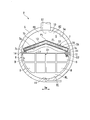
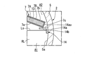
- FIG. 2 is a cross-sectional view of the evaporator according to the first embodiment of the present invention.
- FIG. 3 is an enlarged view of the support portion in the first embodiment of the present invention.
- the evaporator 2 includes a casing 5, a heat transfer tube group 6, and a demister 7.
- the casing 5 forms a sealed internal space S covering the heat transfer pipe group 6 and the demister 7.
- the liquid refrigerant RL can be stored in the internal space S of the casing 5.
- the casing 5 communicates the evaporator outlet 10 for discharging the evaporated gas refrigerant RG toward the turbo compressor 1 to the outside, the external pipe for supplying the liquid refrigerant RL, and the internal space S.
- the evaporator inlets 11 of are each formed.
- the casing 5 illustrated in the first embodiment is, for example, a pressure vessel whose cross-sectional profile is formed in an annular shape.
- the casing 5 also has an opening (not shown) for communicating the heat transfer pipe 12 (heat transfer pipe group 6) with an external pipe (not shown) for supplying the fluid C to be cooled. It is formed.
- the heat transfer tube group 6 includes a plurality of heat transfer tubes 12 in which the fluid C to be cooled flows.
- the heat transfer tube group 6 is mainly provided in the lower part of the internal space S of the casing 5.
- the plurality of heat transfer tubes 12 extend in the longitudinal direction of the casing 5 whose cross-sectional profile is formed in an annular shape (the front and back direction of the sheet of FIG. 2: in other words, the direction of the axis O1 of the casing 5).
- the heat transfer tube group 6 is disposed in the liquid phase area A1 below the liquid level Ls of the liquid refrigerant RL accumulated in the lower part of the internal space S in the casing 5. In other words, the heat transfer tube 12 is immersed in the liquid refrigerant RL.
- the position of the liquid level Ls is not limited to this position.
- the heat transfer tube group 6 is divided into a plurality of blocks B in a direction orthogonal to the axis O1 of the casing 5 (hereinafter simply referred to as the width direction Dw of the casing 5).
- Each of the plurality of blocks B has a rectangular shape or a shape close to a rectangular shape in which a part of the sides of the rectangular shape is replaced with a convex curved surface in the cross-sectional view shown in FIG.
- the blocks B are arranged in the width direction Dw with a slight gap therebetween.
- a large number of heat transfer tubes 12 are disposed inside each block B of the heat transfer tube group 6 exemplified in this embodiment.
- the large number of heat transfer tubes 12 are arranged at predetermined intervals such that the distances between adjacent heat transfer tubes 12 are substantially equal.
- the block B is provided in 2 steps up and down in FIG. 2 is illustrated, you may provide only one step and may provide three or more steps.
- the demister 7 collects droplets (liquid refrigerant RL) contained in the vaporized gas refrigerant RG.
- the demister 7 is accommodated in the gas phase region A2 of the internal space S above the liquid level Ls, and is provided so as to cover the liquid level Ls of the liquid refrigerant RL from above.
- the demister 7 includes, for example, a demister main body 7A formed in a closely-packed wire mesh shape, and a frame 7B supporting the demister main body 7A.
- the demister main body 7A includes an inlet 7a facing the liquid surface Ls and an outlet 7b opposite to the inlet 7a.
- the demister 7 allows passage of the gas refrigerant RG from the inlet 7a to the outlet 7b, and brings droplets contained in the gas refrigerant RG passing through the demister 7 into contact with the wire mesh and is captured.
- the demister 7 exemplified in this embodiment includes two inclined portions 13. These inclined portions 13 are respectively directed toward the central portion of the casing 5 (in other words, the side closer to the axis O1) along the liquid surface Ls in a cross-sectional view intersecting the axis O2 of the heat transfer tube 12 (see FIG. 2) It is formed to be away from the surface Ls. As a result, the demister 7 is disposed in the central portion in the width direction Dw above the rise of the floss level FL generated by the boiling or the like of the liquid refrigerant. Then, the two inclined portions 13 are connected on the center plane S1 in the width direction Dw including the axis O1.
- the inclined portions 13 illustrated in the first embodiment are each formed in a flat plate shape.
- the two inclined portions 13 are arranged symmetrically with reference to the central plane S1. That is, the demister 7 has a chevron shape (in other words, an inverted V shape) in which the vertex position Pt which is the top of the demister 7 is disposed on the central plane S1.
- the inclination angle of the inclined portion 13 based on the liquid level Ls may be 30 degrees or less. In this way, the flow velocity of the gas refrigerant RG in the upper part of the demister 7, ie, in the vicinity of the top, can be suppressed low, and droplets from the outlet 7b near the vertex position Pt of the demister 7 scatter toward the evaporator outlet 10. Can be suppressed.
- the demister 7 is in a direction in which the liquid surface Ls spreads in the cross section shown in FIG. 2, that is, in the width direction Dw from the position of the central surface S1 mentioned above to a position slightly closer to the central surface S1 than the inner surface 5a of the casing 5. It is formed so as to lead. That is, the demister 7 is not in direct contact with the inner surface 5 a of the casing 5.
- the demister 7 is supported by the support portion 14 at its two end edges 7c closer to the liquid surface Ls.
- the two edges 7c illustrated in this embodiment have planes respectively perpendicular to the surface on the inlet 7a side of the demister 7 and the surface on the outlet 7b side.
- the support portion 14 supports the edge 7 c of the demister 7 from below.
- the support portions 14 each include a support portion main body 14 a and a fixing portion 14 b.
- the support portion main body 14a extends from the positions on both sides of the inner surface 5a of the casing 5 slightly above the liquid surface Ls and on both sides in the width direction Dw toward the central surface S1.
- the fixing portion 14 b extends downward from the base of the support portion body 14 a along the inner surface 5 a.
- the support portion 14 illustrated in this embodiment extends in the direction of the axis O1 of the casing 5 (in other words, in the direction of the axis O2 of the heat transfer tube 12), and the upper surface 14au is a flat surface extending in the horizontal direction.
- the heat transfer tube group 6 is omitted for convenience of illustration (the same applies to FIG. 4 of the second embodiment).
- the support portion 14 is formed to have an L-shaped cross section by the support portion main body 14a and the fixing portion 14b is exemplified, but the shape is limited to the above shape as long as the demister 7 can be supported from below. (The same applies to the second embodiment). Moreover, the length which the support part main body 14a extends can be formed shorter, making the edge 7c into a supportable length. By doing this, it is possible to suppress the flow of the gas refrigerant RG in the internal space S from being hindered by the support portion main body 14a.
- the area of the demister 7 can be increased more than when the demister is disposed flat along the liquid level Ls. Therefore, it is possible to increase the upper limit value of the gas passing rate of the demister 7 and the collection load as compared to the case where the demister is disposed flat along the liquid surface Ls. Furthermore, since the demister 7 is separated from the liquid surface Ls toward the central portion in the width direction Dw of the casing 5 by the inclined portion 13, the bulge of the floss level FL generated in the vicinity of the axis O1 of the casing 5 (shown by a broken line in FIG. 2) The demister 7 can be prevented from sinking into the liquid refrigerant RL. Therefore, scattering of droplets from the outlet 7 b side of the demister 7 can be suppressed. As a result, it is possible to reduce the size or increase the amount of heat exchange while suppressing the carryover in which the droplets are drawn into the turbo compressor 1.
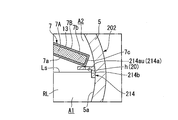
- FIG. 4 is a cross-sectional view of the support portion in the second embodiment of the present invention.
- the evaporator 202 in the second embodiment includes a casing 5, a heat transfer tube group (not shown), and a demister 7.
- the heat transfer tube group 6 and the demister 7 have the same configuration as the heat transfer tube group and the demister 7 of the first embodiment described above, and thus the detailed description will be omitted.
- a support 214 is fixed to the inner surface 5 a of the casing 5.
- the support part 214 supports the edge 7c of the demister 7 from the lower side similarly to the support part 14 of 1st embodiment.
- the support portion 214 includes a support portion main body 214a and a fixing portion 214b.
- the support portion main body 214a extends from the positions on both sides of the inner surface 5a of the casing 5 slightly above the liquid surface Ls and on both sides in the width direction Dw toward the central surface S1.
- the fixing portion 214b extends downward from the support portion main body 214a along the inner surface 5a.
- the support portion 214 illustrated in the second embodiment extends in the direction of the axis O1 of the casing 5 (in other words, the direction of the axis O2 of the heat transfer tube 12), and the upper surface 214au is a flat surface extending in the horizontal direction.
- the support portion 214 is a through portion 20 having a hole formed vertically at a position between the edge 7 c and the inner surface 5 a of the casing 5 in the width direction Dw in a cross sectional view intersecting the axis O 2 of the heat transfer tube 12. Is equipped.
- a plurality of slits h (through holes) penetrating in a direction perpendicular to the upper surface 214 au of the support portion main body 214 a are formed as holes penetrating vertically.
- the slits h extend in the direction of the axis O1, and a plurality of slits h are arranged at predetermined intervals in the direction of the axis O1.
- the slit h extended in the axis line O1 direction was illustrated as a hole to penetrate, a round hole, a long hole, etc. may be sufficient.
- the droplet collected by the demister 7 travels along the inclined portion 13 to reach the edge 7c by its own weight, and in this case, the droplet which has reached the edge 7c is It can be made to fall to liquid phase field A1 through slit h. As a result, the droplets collected by the demister 7 can be returned to the liquid phase region A1 again and evaporated by the heat transfer tube group 6.
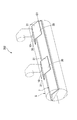
- FIG. 5 is a perspective view showing the internal structure of the casing of the evaporator according to the third embodiment of the present invention.
- FIG. 6 is a cross-sectional view intersecting the axis of the heat transfer tube of the evaporator according to the third embodiment of the present invention.
- the evaporator 302 in the third embodiment includes the casing 5, the heat transfer tube group 6 (not shown), and the demister 7, as in the first and second embodiments described above. Is equipped.
- the evaporator 302 in this 3rd embodiment is further provided with the blowing-up prevention board 30. As shown in FIG.
- the blow-up preventing plate 30 prevents the droplets collected by the demister 7 from being sucked up from the outlet of the demister 7 to the evaporator outlet 10.
- the blow-up preventing plate 30 is disposed at a position overlapping the evaporator outlet 10 in the direction of the axis O1, that is, vertically below the evaporator outlet 10.
- the evaporator 302 in the example of FIG. 5 is provided with two blowout prevention plates 30 because the evaporator outlets 10 are provided at two places.
- the blow-up prevention plate 30 is formed along the demister 7. More specifically, the blow-up prevention plate 30 has two inclined plate portions 31, and these inclined plate portions 31 are substantially parallel to the inclined portion 13 of the demister 7 (the inclination angle of the inclined portion 13 substantially At the same angle). That is, the blow-up prevention plate 30 is formed in a mountain shape (in other words, an inverted V-shape).
- the inclined plate portions 31 are disposed above the inclined portions 13 of the demister 7 at predetermined intervals. That is, the distance between the demister 7 and the blow-up preventing plate 30 in the vertical direction is substantially equal in the entire width direction Dw of the casing 5.
- the blow-up prevention plate 30 is disposed at a position overlapping the evaporator outlet 10 in the direction of the axis O1.
- the gas refrigerant RG that has passed through the demister 7 disposed at a position overlapping the evaporator outlet 10 in the direction of the axis O1 bypasses the blow-up prevention plate 30 and reaches the evaporator outlet 10. Therefore, it is possible to prevent the droplets collected in the demister 7 disposed at a position overlapping the evaporator outlet 10 from being sucked into the evaporator outlet 10.
- the blow-up prevention plate 30 includes the flat inclined plate portion 31
- the shape of the inclined plate portion 31 is not limited to the flat shape as long as it conforms to the inclined portion 13 of the demister 7. .
- FIG. 7 is a cross-sectional view of the evaporator corresponding to FIG. 2 in the fourth embodiment of the present invention.
- the evaporator 402 in the fourth embodiment includes a casing 5, a heat transfer tube group 306, a demister 7, and a blow-up preventing plate 30.
- the blow-up prevention plate 30 may be omitted.
- the casing 5 and the demister 7 have the same configuration as the first to third embodiments described above, and thus the detailed description will be omitted.
- the heat transfer pipe group 406 includes a plurality of heat transfer pipes 412 in which the fluid C to be cooled flows.
- the heat transfer tube group 406 is a position close to the end of the casing 5 in a direction in which the liquid level Ls spreads (hereinafter simply referred to as “close to both sides in the width direction Dw of the casing 5
- the number of heat transfer tubes 412 arranged in the direction intersecting the liquid level Ls is greater at a position closer to the central portion of the casing 5 (hereinafter referred to simply as “a position closer to the center plane S1”) than “position” .
- the heat transfer pipe group 406 illustrated in the fourth embodiment is divided into a plurality of blocks B in the width direction Dw of the casing 5.
- the plurality of blocks B are arranged in the width direction Dw with a slight gap therebetween in the cross sectional view shown in FIG.
- four blocks B are arranged in the width direction Dw.
- the total height H1 of the two blocks B1 arranged at a position close to the central plane S1 is greater than the height H2 of the two blocks B2 arranged at a position close to both sides in the width direction Dw of the casing 5 It is getting bigger.
- the total height H2 of the two blocks B2 arranged at positions close to both sides in the width direction Dw of the casing 5 is kept low, and the two blocks arranged at a position closer to the center plane S1 by that amount.
- the total height H1 of B1 is high.
- the number of heat transfer tubes 412 aligned in the direction intersecting the liquid level Ls is closer to the center plane S1 than the positions closer to both sides in the width direction Dw of the casing 5 in the spreading direction of the liquid level Ls. Is getting more.
- the number of heat transfer tubes 412 arranged at positions close to both sides in the width direction Dw of the casing 5 can be reduced, so positions close to both sides in the width direction Dw of the casing 5 Can suppress the floss level FL of the Therefore, it is possible to suppress the edge 7c of the demister 7 from being submerged in the liquid refrigerant RL due to the floss level FL rising.
- the demister 7 is disposed apart from the liquid surface Ls, so it is possible to suppress the demister 7 from being submerged in the liquid refrigerant RL.
- the fourth embodiment described above the case is described where the total height H1 of the blocks B1 aligned in the vertical direction is larger than the total height H2 of the blocks B2 aligned in the vertical direction.
- the installation number of the heat pipes 412 in other words, the arrangement density of the heat transfer pipes 412
- the number of heat transfer pipes 412 near the both sides in the width direction Dw of the casing 5 is reduced.
- the number of heat transfer tubes 412 may be increased.
- the fourth embodiment described above the case where the four blocks of the heat transfer pipe group 406 are arranged in the direction in which the liquid surface Ls spreads is described in a cross sectional view intersecting the axis O2 of the heat transfer pipe 412.
- the arrangement of the blocks B is not limited to the arrangement exemplified in the fourth embodiment.
- vertex position Pt of demister 7 was arrange
- the arrangement of the vertex positions Pt is not limited to the center plane S1.
- the vertex position Pt may be deviated from the center plane S1 within a range that can avoid rising of the floss level FL, for example.
- the corner portion may be chamfered by a curved surface, a plane, or a combination thereof.
- the heat transfer tube group 6 in the embodiment described above is described as being disposed in the liquid phase area A1 below the liquid level Ls, it may be disposed below the floss level FL.
- the refrigeration system 100 may be equipped with compressors other than the turbo compressor 1.
Landscapes
- Engineering & Computer Science (AREA)
- Physics & Mathematics (AREA)
- Thermal Sciences (AREA)
- Mechanical Engineering (AREA)
- General Engineering & Computer Science (AREA)
- Heat-Exchange Devices With Radiators And Conduit Assemblies (AREA)
Priority Applications (2)
| Application Number | Priority Date | Filing Date | Title |
|---|---|---|---|
| CN201880067338.5A CN111226081A (zh) | 2017-10-17 | 2018-10-11 | 蒸发器及制冷系统 |
| US16/756,027 US11448435B2 (en) | 2017-10-17 | 2018-10-11 | Evaporator and refrigeration system |
Applications Claiming Priority (2)
| Application Number | Priority Date | Filing Date | Title |
|---|---|---|---|
| JP2017-201077 | 2017-10-17 | ||
| JP2017201077A JP6944337B2 (ja) | 2017-10-17 | 2017-10-17 | 蒸発器及び冷凍システム |
Publications (1)
| Publication Number | Publication Date |
|---|---|
| WO2019078084A1 true WO2019078084A1 (ja) | 2019-04-25 |
Family
ID=66173246
Family Applications (1)
| Application Number | Title | Priority Date | Filing Date |
|---|---|---|---|
| PCT/JP2018/037934 Ceased WO2019078084A1 (ja) | 2017-10-17 | 2018-10-11 | 蒸発器及び冷凍システム |
Country Status (4)
| Country | Link |
|---|---|
| US (1) | US11448435B2 (enExample) |
| JP (1) | JP6944337B2 (enExample) |
| CN (1) | CN111226081A (enExample) |
| WO (1) | WO2019078084A1 (enExample) |
Families Citing this family (1)
| Publication number | Priority date | Publication date | Assignee | Title |
|---|---|---|---|---|
| CN113304563A (zh) * | 2021-06-30 | 2021-08-27 | 芜湖凯博环保科技股份有限公司 | 一种冷却塔用汽水分离装置 |
Citations (13)
| Publication number | Priority date | Publication date | Assignee | Title |
|---|---|---|---|---|
| JPS4889042U (enExample) * | 1972-01-28 | 1973-10-26 | ||
| JPS50134064U (enExample) * | 1974-04-19 | 1975-11-05 | ||
| JPS515759U (enExample) * | 1974-07-01 | 1976-01-16 | ||
| JPS54120753U (enExample) * | 1978-02-13 | 1979-08-23 | ||
| JPS57179596A (en) * | 1981-04-30 | 1982-11-05 | Mitsubishi Heavy Ind Ltd | Heat exchanger |
| JPS58183471U (ja) * | 1982-05-27 | 1983-12-07 | ダイキン工業株式会社 | 満液式蒸発器 |
| JP2001355994A (ja) * | 2000-06-12 | 2001-12-26 | Toyo Radiator Co Ltd | 気体冷却用積層型熱交換器 |
| JP2002333236A (ja) * | 2001-05-07 | 2002-11-22 | Mitsubishi Heavy Ind Ltd | 蒸発器及びこれを有する冷凍機 |
| JP2004100985A (ja) * | 2002-09-05 | 2004-04-02 | Mitsubishi Heavy Ind Ltd | 蒸発器及び冷凍機 |
| JP2004340546A (ja) * | 2003-05-19 | 2004-12-02 | Mitsubishi Heavy Ind Ltd | 冷凍機用蒸発器 |
| JP2008138891A (ja) * | 2006-11-30 | 2008-06-19 | Mitsubishi Heavy Ind Ltd | 冷凍機用の蒸発器 |
| JP2015518132A (ja) * | 2012-04-23 | 2015-06-25 | ダイキン アプライド アメリカズ インコーポレィティッド | 熱交換器 |
| JP2016065676A (ja) * | 2014-09-25 | 2016-04-28 | 三菱重工業株式会社 | 蒸発器及び冷凍機 |
Family Cites Families (14)
| Publication number | Priority date | Publication date | Assignee | Title |
|---|---|---|---|---|
| US2059725A (en) * | 1934-03-09 | 1936-11-03 | Carrier Engineering Corp | Shell and tube evaporator |
| US3412569A (en) * | 1966-02-21 | 1968-11-26 | Carrier Corp | Refrigeration apparatus |
| CN2274322Y (zh) * | 1996-10-31 | 1998-02-11 | 张家港市沙工化机厂 | 蒸发器除沫装置 |
| CN2441094Y (zh) * | 2000-09-26 | 2001-08-01 | 上海奥申机械有限公司 | 一种制冷压缩机铁管储液器过滤装置的改进结构 |
| JP2002340444A (ja) | 2001-05-18 | 2002-11-27 | Mitsubishi Heavy Ind Ltd | 蒸発器及びこれを有する冷凍機 |
| US6910349B2 (en) * | 2002-08-06 | 2005-06-28 | York International Corporation | Suction connection for dual centrifugal compressor refrigeration systems |
| US6868695B1 (en) * | 2004-04-13 | 2005-03-22 | American Standard International Inc. | Flow distributor and baffle system for a falling film evaporator |
| US7421855B2 (en) * | 2007-01-04 | 2008-09-09 | Trane International Inc. | Gas trap distributor for an evaporator |
| US8944152B2 (en) * | 2009-07-22 | 2015-02-03 | Johnson Controls Technology Company | Compact evaporator for chillers |
| FI20115125A0 (fi) * | 2011-02-09 | 2011-02-09 | Vahterus Oy | Laite pisaroiden erottamiseksi |
| CN102259941B (zh) * | 2011-06-16 | 2012-11-14 | 大连理工大学 | 一种竖管喷涌沸腾海水蒸发器 |
| CN202328957U (zh) * | 2011-11-23 | 2012-07-11 | 珠海格力电器股份有限公司 | 气液分离器、蒸发器及离心机 |
| CN202328928U (zh) * | 2011-12-07 | 2012-07-11 | 克莱门特捷联制冷设备(上海)有限公司 | 一种满液式壳管蒸发器 |
| CN203908141U (zh) * | 2014-06-19 | 2014-10-29 | 烟台顿汉布什工业有限公司 | 一种满液式蒸发器的气液分离机构 |
-
2017
- 2017-10-17 JP JP2017201077A patent/JP6944337B2/ja active Active
-
2018
- 2018-10-11 WO PCT/JP2018/037934 patent/WO2019078084A1/ja not_active Ceased
- 2018-10-11 US US16/756,027 patent/US11448435B2/en active Active
- 2018-10-11 CN CN201880067338.5A patent/CN111226081A/zh active Pending
Patent Citations (13)
| Publication number | Priority date | Publication date | Assignee | Title |
|---|---|---|---|---|
| JPS4889042U (enExample) * | 1972-01-28 | 1973-10-26 | ||
| JPS50134064U (enExample) * | 1974-04-19 | 1975-11-05 | ||
| JPS515759U (enExample) * | 1974-07-01 | 1976-01-16 | ||
| JPS54120753U (enExample) * | 1978-02-13 | 1979-08-23 | ||
| JPS57179596A (en) * | 1981-04-30 | 1982-11-05 | Mitsubishi Heavy Ind Ltd | Heat exchanger |
| JPS58183471U (ja) * | 1982-05-27 | 1983-12-07 | ダイキン工業株式会社 | 満液式蒸発器 |
| JP2001355994A (ja) * | 2000-06-12 | 2001-12-26 | Toyo Radiator Co Ltd | 気体冷却用積層型熱交換器 |
| JP2002333236A (ja) * | 2001-05-07 | 2002-11-22 | Mitsubishi Heavy Ind Ltd | 蒸発器及びこれを有する冷凍機 |
| JP2004100985A (ja) * | 2002-09-05 | 2004-04-02 | Mitsubishi Heavy Ind Ltd | 蒸発器及び冷凍機 |
| JP2004340546A (ja) * | 2003-05-19 | 2004-12-02 | Mitsubishi Heavy Ind Ltd | 冷凍機用蒸発器 |
| JP2008138891A (ja) * | 2006-11-30 | 2008-06-19 | Mitsubishi Heavy Ind Ltd | 冷凍機用の蒸発器 |
| JP2015518132A (ja) * | 2012-04-23 | 2015-06-25 | ダイキン アプライド アメリカズ インコーポレィティッド | 熱交換器 |
| JP2016065676A (ja) * | 2014-09-25 | 2016-04-28 | 三菱重工業株式会社 | 蒸発器及び冷凍機 |
Also Published As
| Publication number | Publication date |
|---|---|
| US20200309424A1 (en) | 2020-10-01 |
| JP6944337B2 (ja) | 2021-10-06 |
| CN111226081A (zh) | 2020-06-02 |
| JP2019074262A (ja) | 2019-05-16 |
| US11448435B2 (en) | 2022-09-20 |
Similar Documents
| Publication | Publication Date | Title |
|---|---|---|
| US9810458B2 (en) | Falling film evaporator | |
| CN108779968B (zh) | 热交换器 | |
| ES2586914T3 (es) | Intercambiador de calor | |
| US10371422B2 (en) | Condenser with tube support structure | |
| CN113227698B (zh) | 热交换器 | |
| WO2016002723A1 (ja) | 流下液膜式蒸発器 | |
| US20190063801A1 (en) | Evaporator and centrifugal chiller provided with the same | |
| ES2972486T3 (es) | Intercambiador de calor | |
| US20090049861A1 (en) | Heat Exchanger with Sloped Baffles | |
| US20180187932A1 (en) | Evaporator and centrifugal chiller provided with the same | |
| JP2015172469A (ja) | 気液分離器 | |
| KR102170312B1 (ko) | 열교환기 | |
| JPH0526539A (ja) | 熱交換器 | |
| JP2014020755A (ja) | 流下液膜式蒸発器 | |
| EP2118591B1 (en) | Apparatus and method for separating droplets from vaporized refrigerant | |
| JP6626237B2 (ja) | 沸騰式冷却器 | |
| WO2019078084A1 (ja) | 蒸発器及び冷凍システム | |
| US6494058B2 (en) | Plate type condenser | |
| JP2021169893A (ja) | 液冷媒散布装置及び流下液膜式蒸発器 | |
| CN107356029B (zh) | 冷凝器壳管和制冷设备 | |
| EP3396292B1 (en) | Gas cooler | |
| JP7260822B2 (ja) | 液冷媒散布装置及び流下液膜式蒸発器 | |
| CN113195997B (zh) | 热交换器 | |
| JP2013029257A (ja) | コンデンサ | |
| CN107421179B (zh) | 闪发器 |
Legal Events
| Date | Code | Title | Description |
|---|---|---|---|
| 121 | Ep: the epo has been informed by wipo that ep was designated in this application |
Ref document number: 18868002 Country of ref document: EP Kind code of ref document: A1 |
|
| NENP | Non-entry into the national phase |
Ref country code: DE |
|
| 122 | Ep: pct application non-entry in european phase |
Ref document number: 18868002 Country of ref document: EP Kind code of ref document: A1 |