WO2019077755A1 - Pointe avant d'endoscope, endoscope et procédé de production de pointe avant d'endoscope - Google Patents
Pointe avant d'endoscope, endoscope et procédé de production de pointe avant d'endoscope Download PDFInfo
- Publication number
- WO2019077755A1 WO2019077755A1 PCT/JP2017/038083 JP2017038083W WO2019077755A1 WO 2019077755 A1 WO2019077755 A1 WO 2019077755A1 JP 2017038083 W JP2017038083 W JP 2017038083W WO 2019077755 A1 WO2019077755 A1 WO 2019077755A1
- Authority
- WO
- WIPO (PCT)
- Prior art keywords
- channel
- imaging device
- light guide
- endoscope
- contact surface
- Prior art date
Links
Images


Classifications
-
- G—PHYSICS
- G02—OPTICS
- G02B—OPTICAL ELEMENTS, SYSTEMS OR APPARATUS
- G02B23/00—Telescopes, e.g. binoculars; Periscopes; Instruments for viewing the inside of hollow bodies; Viewfinders; Optical aiming or sighting devices
- G02B23/24—Instruments or systems for viewing the inside of hollow bodies, e.g. fibrescopes
- G02B23/2407—Optical details
- G02B23/2423—Optical details of the distal end
- G02B23/243—Objectives for endoscopes
-
- A—HUMAN NECESSITIES
- A61—MEDICAL OR VETERINARY SCIENCE; HYGIENE
- A61B—DIAGNOSIS; SURGERY; IDENTIFICATION
- A61B1/00—Instruments for performing medical examinations of the interior of cavities or tubes of the body by visual or photographical inspection, e.g. endoscopes; Illuminating arrangements therefor
- A61B1/00064—Constructional details of the endoscope body
- A61B1/0011—Manufacturing of endoscope parts
-
- A—HUMAN NECESSITIES
- A61—MEDICAL OR VETERINARY SCIENCE; HYGIENE
- A61B—DIAGNOSIS; SURGERY; IDENTIFICATION
- A61B1/00—Instruments for performing medical examinations of the interior of cavities or tubes of the body by visual or photographical inspection, e.g. endoscopes; Illuminating arrangements therefor
- A61B1/012—Instruments for performing medical examinations of the interior of cavities or tubes of the body by visual or photographical inspection, e.g. endoscopes; Illuminating arrangements therefor characterised by internal passages or accessories therefor
- A61B1/018—Instruments for performing medical examinations of the interior of cavities or tubes of the body by visual or photographical inspection, e.g. endoscopes; Illuminating arrangements therefor characterised by internal passages or accessories therefor for receiving instruments
-
- A—HUMAN NECESSITIES
- A61—MEDICAL OR VETERINARY SCIENCE; HYGIENE
- A61B—DIAGNOSIS; SURGERY; IDENTIFICATION
- A61B1/00—Instruments for performing medical examinations of the interior of cavities or tubes of the body by visual or photographical inspection, e.g. endoscopes; Illuminating arrangements therefor
- A61B1/04—Instruments for performing medical examinations of the interior of cavities or tubes of the body by visual or photographical inspection, e.g. endoscopes; Illuminating arrangements therefor combined with photographic or television appliances
- A61B1/05—Instruments for performing medical examinations of the interior of cavities or tubes of the body by visual or photographical inspection, e.g. endoscopes; Illuminating arrangements therefor combined with photographic or television appliances characterised by the image sensor, e.g. camera, being in the distal end portion
- A61B1/051—Details of CCD assembly
-
- A—HUMAN NECESSITIES
- A61—MEDICAL OR VETERINARY SCIENCE; HYGIENE
- A61B—DIAGNOSIS; SURGERY; IDENTIFICATION
- A61B1/00—Instruments for performing medical examinations of the interior of cavities or tubes of the body by visual or photographical inspection, e.g. endoscopes; Illuminating arrangements therefor
- A61B1/06—Instruments for performing medical examinations of the interior of cavities or tubes of the body by visual or photographical inspection, e.g. endoscopes; Illuminating arrangements therefor with illuminating arrangements
- A61B1/07—Instruments for performing medical examinations of the interior of cavities or tubes of the body by visual or photographical inspection, e.g. endoscopes; Illuminating arrangements therefor with illuminating arrangements using light-conductive means, e.g. optical fibres
-
- G—PHYSICS
- G02—OPTICS
- G02B—OPTICAL ELEMENTS, SYSTEMS OR APPARATUS
- G02B23/00—Telescopes, e.g. binoculars; Periscopes; Instruments for viewing the inside of hollow bodies; Viewfinders; Optical aiming or sighting devices
- G02B23/24—Instruments or systems for viewing the inside of hollow bodies, e.g. fibrescopes
- G02B23/2407—Optical details
- G02B23/2461—Illumination
- G02B23/2469—Illumination using optical fibres
-
- G—PHYSICS
- G02—OPTICS
- G02B—OPTICAL ELEMENTS, SYSTEMS OR APPARATUS
- G02B23/00—Telescopes, e.g. binoculars; Periscopes; Instruments for viewing the inside of hollow bodies; Viewfinders; Optical aiming or sighting devices
- G02B23/24—Instruments or systems for viewing the inside of hollow bodies, e.g. fibrescopes
- G02B23/26—Instruments or systems for viewing the inside of hollow bodies, e.g. fibrescopes using light guides
-
- H—ELECTRICITY
- H04—ELECTRIC COMMUNICATION TECHNIQUE
- H04N—PICTORIAL COMMUNICATION, e.g. TELEVISION
- H04N23/00—Cameras or camera modules comprising electronic image sensors; Control thereof
- H04N23/50—Constructional details
- H04N23/54—Mounting of pick-up tubes, electronic image sensors, deviation or focusing coils
-
- H—ELECTRICITY
- H04—ELECTRIC COMMUNICATION TECHNIQUE
- H04N—PICTORIAL COMMUNICATION, e.g. TELEVISION
- H04N23/00—Cameras or camera modules comprising electronic image sensors; Control thereof
- H04N23/50—Constructional details
- H04N23/55—Optical parts specially adapted for electronic image sensors; Mounting thereof
-
- H—ELECTRICITY
- H04—ELECTRIC COMMUNICATION TECHNIQUE
- H04N—PICTORIAL COMMUNICATION, e.g. TELEVISION
- H04N23/00—Cameras or camera modules comprising electronic image sensors; Control thereof
- H04N23/50—Constructional details
- H04N23/555—Constructional details for picking-up images in sites, inaccessible due to their dimensions or hazardous conditions, e.g. endoscopes or borescopes
Definitions
- the present invention relates to an endoscope tip, an endoscope, and a method of manufacturing the endoscope tip.
- an endoscope acquires an in-vivo image of an inside of a subject by inserting a flexible insertion portion having an elongated shape in which an imaging device is provided at a tip end into a subject such as a patient.
- a first unit having a treatment tool channel having a substantially semi-cylindrical cross-sectional shape in a substantially cylindrical tip cylinder for the purpose of reducing the diameter of the tip portion.
- an endoscope having a second unit having an object image observation means see Patent Document 1.
- the first unit having the treatment instrument channel, the second unit comprising the imaging device, and the first unit and the second unit
- the first unit When designed to contact the inner wall of the tip cylinder (the sum of the outer diameters of the first unit and the second unit is substantially equal to the inner diameter of the tip cylinder), It becomes difficult to insert.
- the light guide is arranged in a semi-cylindrical shape around the treatment instrument channel, but it is also troublesome to arrange the light guide in a semi-cylindrical shape around the treatment instrument channel It takes
- the tip portion becomes larger in diameter and the treatment tool channel, light guide and imaging device Alignment is difficult.
- the present invention has been made in view of the above, and aims to reduce the diameter of the distal end portion of the endoscope, and is excellent in the positioning accuracy of the built-in items such as imaging devices accommodated in the distal end portion. It is an object of the present invention to provide a method of manufacturing a distal end, an endoscope and an endoscopic tip.
- an endoscope tip portion includes a bowl-shaped channel into which a treatment tool is inserted and a light guide for guiding illumination light emitted from a light source. And an imaging device for capturing an image of an observation site illuminated by illumination light from the light guide, and a fixing made of a cylindrical outer shape made of resin for sealing the periphery of the channel, the light guide, and the imaging device. A member, and the channel and the imaging device, and the light guide and the channel and / or the imaging device are in contact with each other at contact surfaces.
- a groove is formed on the contact surface of the channel with the imaging device or the contact surface of the imaging device with the channel. It features.
- a groove or a protrusion is formed on the contact surface of the channel with the light guide or the contact surface of the imaging device with the light guide It is characterized by
- the endoscope tip portion has a resin covering portion covering the outer periphery of the channel or the imaging device, and the contact of the covering portion on the channel with the imaging device A groove is formed on the surface or the contact surface of the cover on the imaging device with the channel, and the contact surface of the cover on the channel with the light guide or the coating on the imaging device A groove or a projection is formed in the contact portion of the portion with the channel.
- the tip end is on the outer periphery of the covering portion on the channel or the channel and the outer periphery of the covering portion on the imaging device or the imaging device It is characterized in that at least three positioning projections made of resin which are exposed on the outer periphery of the fixing member are formed.
- the channel integrated in the inside, the imaging device, and the light guide are housed, and the bottom portion has a hole for fitting the channel. It has a bowl-like outermost frame portion formed of a transparent material, and the fixing member is disposed between the outermost frame portion and the integrated channel, the imaging device, and the light guide. It is characterized in that it is formed by filling a resin.
- An endoscope according to the present invention is characterized by including the endoscope tip portion described in any one of the above.
- a method of manufacturing an endoscope tip portion according to the present invention is the method of manufacturing an endoscope tip portion according to any one of the above, comprising: a channel and an imaging device; Alternatively, an integral process of integrating the imaging devices in contact with each other at a contact surface, and a mold having the channel integrated with the channels, the imaging device, and the fitting protrusion for fitting the light guide to the channel
- the method is characterized by including an arranging step of inserting and arranging the fitting projection in the channel, and a forming step of filling a resin in the form and forming a fixing member.
- a method of manufacturing an endoscope tip portion according to the present invention is the method of manufacturing an endoscope tip portion described above, which comprises a channel and an imaging device, and a light guide and the channel and / or the imaging device.
- the present invention it is possible to reduce the diameter of the distal end portion of the endoscope and to improve the positional accuracy of the built-in component accommodated in the distal end portion.
- FIG. 1 is a view schematically showing an entire configuration of an endoscope system according to a first embodiment of the present invention.
- FIG. 2 is a cross-sectional view of the distal end portion of the endoscope according to the first embodiment of the present invention in the vertical plane including the optical axis.
- FIG. 3 is a cross-sectional view orthogonal to the optical axis of the distal end portion of the endoscope according to the first embodiment of the present invention.
- FIG. 4 is a front view of the channel of FIG.
- FIG. 5 is a view for explaining the method of manufacturing the distal end portion of the endoscope according to the first embodiment of the present invention.
- FIG. 6 is a cross-sectional view orthogonal to the optical axis of the distal end portion of the endoscope according to the first modification of the first embodiment of the present invention.
- FIG. 7 is a cross-sectional view orthogonal to the optical axis of the distal end portion of the endoscope according to the second modification of the first embodiment of the present invention.
- FIG. 8 is a front view of a channel according to Variation 3 of Embodiment 1 of the present invention.
- FIG. 9 is a cross-sectional view orthogonal to the optical axis of the distal end portion of the endoscope according to the second embodiment of the present invention.
- FIG. 10 is a view for explaining the method for manufacturing the distal end portion of the endoscope according to the second embodiment of the present invention.
- FIG. 11 is a cross-sectional view orthogonal to the optical axis of the distal end portion according to the third embodiment of the present invention.
- FIG. 12 is a view for explaining the method for manufacturing the
- an endoscope system provided with an endoscope tip portion will be described as a mode for carrying out the present invention (hereinafter, referred to as "embodiment"). Further, the present invention is not limited by the embodiment. Furthermore, the drawings referred to in the following description merely schematically show the shapes, sizes, and positional relationships to the extent that the contents of the present invention can be understood. That is, the present invention is not limited to only the shapes, sizes, and positional relationships illustrated in the respective drawings. Furthermore, also between the drawings, there are included parts that differ in size and proportion from one another.
- FIG. 1 is a view schematically showing an entire configuration of an endoscope system 1 according to a first embodiment of the present invention.
- an endoscope system 1 according to the present embodiment is an endoscope 2 introduced into a subject, imaging an inside of the subject to generate an image signal of the inside of the subject,
- An information processing apparatus 3 for performing predetermined image processing on an image signal captured by the endoscope 2 and controlling each part of the endoscope system 1, a light source apparatus 4 for generating illumination light of the endoscope 2, and information processing
- a display device 5 for displaying an image of an image signal after image processing by the device 3.
- the endoscope 2 includes an insertion portion 6 inserted into a subject, an operation portion 7 on the proximal end side of the insertion portion 6 that the operator holds, and a flexible universal that extends from the operation portion 7. And a code 8.
- the insertion portion 6 is realized by using a light guide made of an illumination fiber, an electric cable, an optical fiber, or the like.
- the insertion portion 6 has a distal end portion 6a incorporating an imaging device described later, a bendable bending portion 6b formed of a plurality of bending pieces, and flexibility provided on the proximal end side of the bending portion 6b. And a flexible tube portion 6c.
- the distal end portion 6a includes an illumination unit that illuminates the inside of the subject via an illumination lens, an observation unit that images the inside of the subject, an opening that communicates the treatment tool channel, and an air supply / water supply nozzle (not shown) Is provided.
- the operation unit 7 includes a bending knob 7a that bends the bending unit 6b in the vertical and horizontal directions, a treatment tool insertion unit 7b in which a treatment tool such as a forceps or a laser knife is inserted into a body cavity of a subject, and an information processing apparatus 3.
- a plurality of switch units 7c for operating peripheral devices such as a light source device 4, an air supply device, a water supply device, and a gas supply device.
- the treatment tool inserted from the treatment tool insertion portion 7 b is exposed from the opening at the tip of the insertion portion 6 through the treatment tool channel provided inside.
- the universal cord 8 is configured using a light guide made of an illumination fiber, a cable or the like.
- the universal cord 8 is branched at the proximal end, and one branched end is the connector 8 a and the other proximal end is the connector 8 b.
- the connector 8 a is detachably attached to the connector of the information processing device 3.
- the connector 8 b is detachable from the light source device 4.
- the universal cord 8 propagates the illumination light emitted from the light source device 4 to the tip 6 a via the connector 8 b and the light guide made of the illumination fiber. Also, the universal cord 8 transmits an image signal captured by an imaging device described later to the information processing device 3 via the cable and the connector 8a.
- the information processing device 3 performs predetermined image processing on the image signal output from the connector 8 a and controls the entire endoscope system 1.
- the light source device 4 is configured using a light source that emits light, a condenser lens, and the like.
- the light source device 4 emits light from the light source under the control of the information processing device 3 and transmits an object, which is a subject, to the endoscope 2 connected via the light guide composed of the connector 8 b and the illumination fiber of the universal cord 8. Supply as illumination light to the inside of the sample.
- the display device 5 is configured using a display or the like using liquid crystal or organic EL (Electro Luminescence).
- the display device 5 displays various information including an image subjected to predetermined image processing by the information processing device 3 through the video cable 5a. Thereby, the operator can determine the observation and the symptom of the desired position in the subject by operating the endoscope 2 while looking at the image (in-vivo image) displayed by the display device 5.
- FIG. 2 is a cross-sectional view in the vertical plane including the optical axis of the distal end portion 6a of the endoscope 2 according to the first embodiment of the present invention.
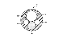
- FIG. 3 is a cross-sectional view orthogonal to the optical axis of the distal end portion 6 a of the endoscope 2 according to the first embodiment of the present invention.
- FIG. 4 is a front view of the channel 70 of FIG.
- the distal end portion 6 a has a bowl-shaped channel 70 into which a treatment tool is inserted, a light guide 80 for guiding illumination light emitted from the light source device 4, and an observation portion illuminated by illumination light from the light guide 80.
- An imaging device 40 for capturing an image, and a channel 70, a light guide 80, and a cylindrical fixing member 60 for sealing the periphery of the imaging device 40 and made of resin are provided.
- the imaging device 40 includes a lens unit 10, an imaging unit 20 disposed on the base end side of the lens unit 10, and a collective cable 50 in which a plurality of signal cables 51 are twisted.
- the lens unit 10 has a plurality of objective lenses 10a, 10b, and 10c, and a lens holder 10d for holding a cover glass 22 described later.
- the imaging unit 20 includes a solid-state imaging device 21 such as a CCD or a CMOS having a light receiving unit for receiving light, a cover glass 22 adhered to the solid imaging device 21 in a state of covering the light receiving unit of the solid-state imaging device 21, And a circuit board 24 electrically and mechanically connected to a plurality of contact pins 23 (one shown) protruding from the back surface side of the imaging device 21.
- the electronic component 25 is mounted on the circuit board 24, and the core wire 52 of the plurality of signal cables 51 for supplying power to the solid-state imaging device 21 or inputting or outputting a signal to the solid-state imaging device 21 on the base end side. Is connected.
- the imaging unit 20 is held by the lens holder 10 d via a cover glass 22 bonded to the solid-state imaging device 21.
- a heat shrinkable tube 26 covers the distal end side of the collective cable 50 from the proximal end side of the lens holder 10 d.
- the space surrounded by the lens holder 10 d and the heat shrinkable tube 26 is filled with an insulating filler 41.
- the channel 70 is composed of a tube made of polytetrafluoroethylene (PTFE) and having a circular cross-sectional inner diameter shape, and a treatment instrument such as forceps is inserted into the channel 70. It is preferable that the PTFE channel 70 be surface-treated on the outer periphery in order to improve the adhesion with the fixing member 60. As shown in FIG. 4, grooves 72a, 72b, and 72c are formed on the outer periphery on the tip end side of the channel 70 and in contact with the imaging device 40 and the light guide 80. The grooves 72 a and 72 c have an arc shape along the outer periphery of the light guide 80, and the groove 72 b has a shape along the outer periphery of the imaging device 40.
- PTFE polytetrafluoroethylene
- the fixing member 60 is made of resin and seals around the integrated channel 70, the light guide 80 and the imaging device 40.
- FIG. 5 is a view for explaining the method of manufacturing the distal end portion 6 a of the endoscope 2 according to the first embodiment of the present invention.
- the channel 70, the light guide 80, and the imaging device 40 are integrated in a state of being in contact with each other at the contact surface.
- grooves 72a, 72b, 72c are formed on the contact surfaces of the channel 70 in contact with the imaging device 40 and the light guide 80, and the imaging device 40 and the light guide 80 are formed in the grooves 72a, 72b, 72c. Integrate in the state of fitting. The integration may be simply performed by fitting the imaging device 40 and the light guide 80 in the grooves 72a, 72b and 72c of the channel 70 and fixing the proximal ends of the channel 70, the imaging device 40 and the light guide 80 with a jig or the like.
- the imaging device 40 and the light guide 80 in order to fix the fitting state of the imaging device 40 and the light guide 80 to the grooves 72a, 72b and 72c, they may be fixed by an adhesive or the like. preferable.
- the fixing member 60 is formed using the molds 90A and 90B.
- the mold 90A has a fitting projection 91 fitted to the channel 70, and the fitting projection 91 is integrated in the channel 70 with the integrated channel 70, the imaging device 40 and the light guide 80. As fitted, they are placed in the molds 90A and 90B.
- the resin is injected from the openings of the molds 90A and 90B into the mold, and the resin is cured and fixed.
- the member 60 is molded to manufacture the tip 6a.
- the molds 90A and 90B having the fitting projections 91 for molding the fixing member 60, the channel 70, the imaging device 40, and the light guide 80 can be accurately disposed in the tip portion 6a.
- the channel 70 having the largest outer diameter and the imaging device 40 having the second largest diameter are fitted in the groove 72b formed on the contact surface of the channel 70. Because they are integrated in the state, it is possible to reduce the diameter of the tip 6a. Furthermore, since the distal end portion 6a of the first embodiment seals the periphery of the channel 70, the imaging device 40, and the light guide 80, which are the built-in members, by the fixing member 60, it can be used as it is in the endoscope 2. , And the time and effort for insertion into the tip frame etc. can be omitted.
- the grooves 72 a, 72 b and 72 c are formed in the channel 70, but the grooves may be formed in the outer periphery of the imaging device 40.
- the groove 72b is formed in the channel 70, and the diameter of the tip 6a is reduced by fitting the imaging device 40 in the groove 72b.
- the channel 70, the imaging device 40, and the light guide If 80 and the channel 70 and / or the imaging device 40 are integrated in contact with each other at the contact surface, and the fixing member 60 seals the periphery of the channel 70, the imaging device 40 and the light guide 80, the tip 6a Can be reduced in diameter.
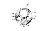
- FIG. 6 is a cross-sectional view orthogonal to the optical axis of the distal end portion 16B of the endoscope according to the first modification of the first embodiment of the present invention.
- the grooves 72a, 72b and 72c are not formed on the outer periphery of the channel 70B, and the protrusions 74a, 74b, 74c and 74d are provided.
- the light guide 80 is disposed between the projection 74a and the projection 74b and between the projection 74c and the projection 74d, and the imaging device 40 is disposed between the projection 74b and the projection 74c.
- Ru Since the light guide 80 and the imaging device 40 are disposed between the protrusions 74a, 74b, 74c and 74d formed at predetermined positions on the outer periphery of the channel 70B, the imaging device 40 and the light guide 80 can be accurately disposed. it can.
- the channel 70B and the imaging device 40, and the channel 70B and the light guide 80 are integrated in contact with each other and sealed and fixed by the fixing member 60B, there is no need to use a tip frame or the like, and the tip portion 16B Can be reduced in diameter.
- FIG. 7 is a cross-sectional view orthogonal to the optical axis of the distal end portion 16A of the endoscope according to the second modification of the first embodiment of the present invention.
- a groove 72b is formed on the outer periphery of the channel 70A, in which the imaging device 40A is fitted. Further, on the outer periphery of the imaging device 40A, a protrusion 43 which defines the arrangement position of the light guide 80 is formed.
- the light guide 80 is disposed between the projection 43 formed at a predetermined position and the channel 70A, and the imaging device 40A is disposed in engagement with the groove 72b of the channel 70A. Since the imaging device 40A is positioned by the groove 72b formed on the outer periphery of the channel 70A, and the light guide 80 is disposed between the outer periphery of the channel 70A and the projection 43 of the imaging device 40A, the imaging device 40A and the light guide 80 are It can be arranged accurately.
- the channel 70A and the imaging device 40A, and the light guide 80 and the channel 70A and the imaging device 40A are integrated in contact with each other and sealed and fixed by the fixing member 60A, there is no need to use a tip frame or the like.
- the tip portion 16A can be reduced in diameter.
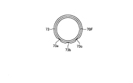
- FIG. 8 is a front view of a channel 70F according to Variation 3 of Embodiment 1 of the present invention.
- the channel 70F according to the third modification has a resin covering portion 73 that covers the outer periphery.
- Grooves 73a, 73b and 73c are formed on the contact surfaces of the covering portion 73 in contact with the imaging device and the light guide, and the imaging device and the light guide are fitted and integrated in the grooves 73a, 73b and 73c.
- the imaging device and the light guide are positioned by the grooves 73a, 73b and 73c, the imaging device and the light guide can be arranged with high accuracy.
- the grooves 73a, 73b, and 73c are formed, but instead of the grooves 73a and 73c, the projections for positioning the light guide on the covering portion 73 or on the imaging device You may provide.
- a covering portion is formed on the imaging device, and a groove portion is formed on the contact surface with the channel of the covering portion covering the imaging device and the light guide. Also, it is possible to reduce the diameter of the tip and to improve the positional accuracy of the built-in parts.
- FIG. 9 is a cross-sectional view orthogonal to the optical axis of the distal end portion 16D of the endoscope according to the second embodiment of the present invention.
- a positioning projection 61 made of resin whose distal end is exposed to the outer periphery of the fixing member 60D is formed.
- FIG. 10 is a diagram for explaining a method of manufacturing the tip 16D according to the second embodiment of the present invention.
- the imaging device 40D and the light guide 80 are fitted in the grooves 72a, 72b and 72c formed in the contact surface of the channel 70D, and the channel 70D, the imaging device 40D and the light guide 80. Unify. This process is the same as that of the first embodiment.
- Positioning protrusions 61 made of resin are formed at three locations in total, one location on the outer periphery of 40D.
- FIG. 10C when the positioning projection 61 arranges the integrated channel 70D, the imaging device 40D and the light guide 80 in the molds 90A-1 and 90B for molding the fixing member 60D. , And the size that can contact the inner circumference of the molds 90A-1 and 90B.
- the resin is injected into the mold from the openings of the molds 90A-1 and 90B, and the resin is The resin is cured to form the fixing member 60D, and the tip 16D is manufactured.
- the tip of the positioning protrusion 61 is exposed to the outer periphery of the fixing member 60D.
- the tip end portion 16D according to the second embodiment has the positioning projection portion 61, the tip end portion 16D having excellent positional accuracy of the built-in is manufactured even when using the molds 90A-1 and 90B without the fitting projection 91. can do.
- grooves 72a, 72b and 72c are formed on the contact surfaces of the channel 70D in contact with the imaging device 40D and the light guide 80.
- the imaging device 40D is formed in the grooves 72a, 72b and 72c.
- FIG. 11 is a cross-sectional view orthogonal to the optical axis of the distal end portion 16E of the endoscope according to Embodiment 3 of the present invention.
- the bottom portion 92 made of a transparent material in which the channel 70, the imaging device 40, and the light guide 80 are accommodated and the hole 93 for fitting the channel 70 is formed.
- an outermost frame portion 90 having a bowl shape.
- FIG. 12 is a diagram for explaining a method of manufacturing the tip end 16E according to the third embodiment of the present invention.
- the integrated channel 70, the imaging device 40, and the tip of the light guide 80 are flush with each other, but in the third embodiment, as shown in FIG.
- the front end of the light source projects by r1 from the front ends of the imaging device 40 and the light guide 80.
- the channel 70 is fitted in the hole 93 of a diameter slightly larger than the outer diameter of the channel 70, and the tip of the channel 70 is aligned with the tip S of the bottom portion 92.
- the protrusion r1 of the channel 70 is preferably substantially the same as the thickness r2 of the bottom surface 92.
- the resin is injected into the mold from the opening of the outermost frame portion 90, and the resin is cured and fixed
- the member 60E is molded to manufacture the tip 16E.
- the outermost frame portion 90 is also used as a mold, the thickness of the fixing member 60E can be reduced, and the diameter reduction of the tip end portion 16E becomes possible. Further, since the channel 70 is fitted in the hole 93, the positional accuracy of the built-in object in the outermost frame 90 can be improved.
Abstract
L'invention concerne : une pointe avant d'endoscope qui permet une réduction du diamètre de celle-ci et présente une excellente précision d'alignement pour des composants (par exemple, un dispositif d'imagerie) logés à l'intérieur de celle-ci; un endoscope; et un procédé de production de la pointe avant d'endoscope. Cette pointe avant d'endoscope est caractérisée : en ce qu'elle est pourvue d'un canal tubulaire (70) dans lequel est inséré un instrument de traitement, d'un guide de lumière (80) pour guider la lumière d'illumination émise par la source de lumière, d'un dispositif d'imagerie (40) pour capturer une image d'un site d'observation éclairé par la lumière d'illumination provenant du guide de lumière (80), et d'un élément de fixation (60) constitué d'une résine et ayant une forme externe cylindrique, pour une étanchéité autour du canal (70), du guide de lumière (80), et du dispositif d'imagerie (40); et en ce que le canal (70) est en contact surfacique avec le dispositif d'imagerie (40), et le guide de lumière (80) est en contact surfacique avec le canal (70) et/ou le dispositif d'imagerie (40).
Priority Applications (2)
| Application Number | Priority Date | Filing Date | Title |
|---|---|---|---|
| PCT/JP2017/038083 WO2019077755A1 (fr) | 2017-10-20 | 2017-10-20 | Pointe avant d'endoscope, endoscope et procédé de production de pointe avant d'endoscope |
| US16/850,083 US11125990B2 (en) | 2017-10-20 | 2020-04-16 | Endoscope distal end portion, endoscope, and method of manufacturing endoscope distal end portion |
Applications Claiming Priority (1)
| Application Number | Priority Date | Filing Date | Title |
|---|---|---|---|
| PCT/JP2017/038083 WO2019077755A1 (fr) | 2017-10-20 | 2017-10-20 | Pointe avant d'endoscope, endoscope et procédé de production de pointe avant d'endoscope |
Related Child Applications (1)
| Application Number | Title | Priority Date | Filing Date |
|---|---|---|---|
| US16/850,083 Continuation US11125990B2 (en) | 2017-10-20 | 2020-04-16 | Endoscope distal end portion, endoscope, and method of manufacturing endoscope distal end portion |
Publications (1)
| Publication Number | Publication Date |
|---|---|
| WO2019077755A1 true WO2019077755A1 (fr) | 2019-04-25 |
Family
ID=66173917
Family Applications (1)
| Application Number | Title | Priority Date | Filing Date |
|---|---|---|---|
| PCT/JP2017/038083 WO2019077755A1 (fr) | 2017-10-20 | 2017-10-20 | Pointe avant d'endoscope, endoscope et procédé de production de pointe avant d'endoscope |
Country Status (2)
| Country | Link |
|---|---|
| US (1) | US11125990B2 (fr) |
| WO (1) | WO2019077755A1 (fr) |
Families Citing this family (2)
| Publication number | Priority date | Publication date | Assignee | Title |
|---|---|---|---|---|
| CN110325098A (zh) | 2016-11-28 | 2019-10-11 | 适内有限责任公司 | 具有可分离一次性轴的内窥镜 |
| USD1018844S1 (en) | 2020-01-09 | 2024-03-19 | Adaptivendo Llc | Endoscope handle |
Citations (3)
| Publication number | Priority date | Publication date | Assignee | Title |
|---|---|---|---|---|
| JP2008253451A (ja) * | 2007-04-03 | 2008-10-23 | Olympus Corp | 内視鏡の先端部構造 |
| JP2016147090A (ja) * | 2016-03-30 | 2016-08-18 | 富士フイルム株式会社 | 電子内視鏡装置及び撮像素子の放熱方法 |
| JP2017023210A (ja) * | 2015-07-16 | 2017-02-02 | パナソニック株式会社 | 内視鏡 |
Family Cites Families (24)
| Publication number | Priority date | Publication date | Assignee | Title |
|---|---|---|---|---|
| JPH0644105B2 (ja) * | 1985-01-14 | 1994-06-08 | オリンパス光学工業株式会社 | 内視鏡 |
| JP3017245B2 (ja) * | 1989-09-22 | 2000-03-06 | オリンパス光学工業株式会社 | 内視鏡 |
| US5430475A (en) * | 1990-06-29 | 1995-07-04 | Olympus Optical Co., Ltd. | Electronic endoscope apparatus having micro array on photoelectric conversion surface |
| US5291375A (en) * | 1991-09-30 | 1994-03-01 | Kabushiki Kaisha Toshiba | Printed circuit board and electric device configured to facilitate bonding |
| JP3462544B2 (ja) | 1993-11-11 | 2003-11-05 | ペンタックス株式会社 | 電子内視鏡の先端部 |
| JPH0852108A (ja) | 1995-08-30 | 1996-02-27 | Olympus Optical Co Ltd | 内視鏡 |
| US5868664A (en) * | 1996-02-23 | 1999-02-09 | Envision Medical Corporation | Electrically isolated sterilizable endoscopic video camera head |
| JP3364574B2 (ja) * | 1997-02-07 | 2003-01-08 | 富士写真光機株式会社 | 内視鏡用撮像装置 |
| US6095970A (en) * | 1997-02-19 | 2000-08-01 | Asahi Kogaku Kogyo Kabushiki Kaisha | Endoscope |
| JP2000023904A (ja) | 1998-07-08 | 2000-01-25 | Olympus Optical Co Ltd | 内視鏡 |
| US7591780B2 (en) * | 2002-03-18 | 2009-09-22 | Sterling Lc | Miniaturized imaging device with integrated circuit connector system |
| JP5030360B2 (ja) * | 2002-12-25 | 2012-09-19 | オリンパス株式会社 | 固体撮像装置の製造方法 |
| JP3684365B2 (ja) * | 2003-02-21 | 2005-08-17 | フジノン株式会社 | 立体電子内視鏡用撮像装置 |
| US8118732B2 (en) * | 2003-04-01 | 2012-02-21 | Boston Scientific Scimed, Inc. | Force feedback control system for video endoscope |
| JP4970877B2 (ja) * | 2006-05-17 | 2012-07-11 | オリンパスメディカルシステムズ株式会社 | 内視鏡 |
| US8520100B2 (en) * | 2009-09-03 | 2013-08-27 | Tower Semiconductor Ltd. | CMOS image sensor pixel without internal sample/hold circuit |
| US9144664B2 (en) * | 2009-10-01 | 2015-09-29 | Sarcos Lc | Method and apparatus for manipulating movement of a micro-catheter |
| JP5452273B2 (ja) * | 2010-02-15 | 2014-03-26 | オリンパス株式会社 | 半導体装置 |
| JP5395829B2 (ja) * | 2011-02-25 | 2014-01-22 | 富士フイルム株式会社 | 内視鏡装置 |
| JP5112575B2 (ja) * | 2011-03-15 | 2013-01-09 | オリンパスメディカルシステムズ株式会社 | 電子内視鏡及び内視鏡システム |
| US9380928B2 (en) * | 2011-06-06 | 2016-07-05 | Fujikura Ltd. | Structure of imaging part in electronic visualized catheter |
| EP2671503A4 (fr) * | 2011-07-12 | 2015-04-01 | Olympus Medical Systems Corp | Appareil de traitement d'image |
| WO2013084548A1 (fr) * | 2011-12-07 | 2013-06-13 | オリンパスメディカルシステムズ株式会社 | Endoscope électronique |
| JP6579601B2 (ja) | 2015-02-17 | 2019-09-25 | オリンパス株式会社 | 内視鏡 |
-
2017
- 2017-10-20 WO PCT/JP2017/038083 patent/WO2019077755A1/fr active Application Filing
-
2020
- 2020-04-16 US US16/850,083 patent/US11125990B2/en active Active
Patent Citations (3)
| Publication number | Priority date | Publication date | Assignee | Title |
|---|---|---|---|---|
| JP2008253451A (ja) * | 2007-04-03 | 2008-10-23 | Olympus Corp | 内視鏡の先端部構造 |
| JP2017023210A (ja) * | 2015-07-16 | 2017-02-02 | パナソニック株式会社 | 内視鏡 |
| JP2016147090A (ja) * | 2016-03-30 | 2016-08-18 | 富士フイルム株式会社 | 電子内視鏡装置及び撮像素子の放熱方法 |
Also Published As
| Publication number | Publication date |
|---|---|
| US20200241280A1 (en) | 2020-07-30 |
| US11125990B2 (en) | 2021-09-21 |
Similar Documents
| Publication | Publication Date | Title |
|---|---|---|
| JP3969827B2 (ja) | 内視鏡装置 | |
| EP2022387A1 (fr) | Endoscope et système d'endoscope | |
| CN108685555B (zh) | 内窥镜及内窥镜中的光学系统的安装方法 | |
| US20160206188A1 (en) | Visualization instrument | |
| CN111031881B (zh) | 内窥镜的连接器装置 | |
| CN106859703B (zh) | 超声波内窥镜以及超声波内窥镜的制造方法 | |
| CN105828689A (zh) | 摄像装置和内窥镜装置 | |
| WO2019077755A1 (fr) | Pointe avant d'endoscope, endoscope et procédé de production de pointe avant d'endoscope | |
| JP6529703B2 (ja) | 撮像ユニット、および内視鏡 | |
| US20230165451A1 (en) | Tip for a single use endoscope, in particular for a single use duodenoscope | |
| US20210307590A1 (en) | Endoscope distal end structure and endoscope | |
| WO2020021637A1 (fr) | Structure d'extrémité d'endoscope et endoscope | |
| US11395582B2 (en) | Endoscope with optimized illumination pathway | |
| US20210333539A1 (en) | Endoscope distal end structure and endoscope | |
| JP5563178B1 (ja) | 内視鏡及び内視鏡の製造方法 | |
| US10271713B2 (en) | Tubed manifold of a multiple viewing elements endoscope | |
| US9537574B2 (en) | Optical transmitting and receiving unit | |
| JP2007296112A (ja) | 内視鏡、内視鏡装置 | |
| WO2020003474A1 (fr) | Structure d'extrémité de pointe d'endoscope et endoscope | |
| JP5851661B1 (ja) | 光送受信ユニット | |
| WO2012017861A1 (fr) | Endoscope | |
| WO2018155066A1 (fr) | Endoscope | |
| US20240008727A1 (en) | Endoscope having a distal tip unit with a bulged portion | |
| JP2004305770A (ja) | 内視鏡装置 | |
| US20230404382A1 (en) | Endoscope comprising a distal tip unit with a camera module |
Legal Events
| Date | Code | Title | Description |
|---|---|---|---|
| 121 | Ep: the epo has been informed by wipo that ep was designated in this application |
Ref document number: 17929083 Country of ref document: EP Kind code of ref document: A1 |
|
| NENP | Non-entry into the national phase |
Ref country code: DE |
|
| 122 | Ep: pct application non-entry in european phase |
Ref document number: 17929083 Country of ref document: EP Kind code of ref document: A1 |
|
| NENP | Non-entry into the national phase |
Ref country code: JP |