WO2019077712A1 - バッテリユニット、香味吸引器、バッテリユニットを制御する方法、及びプログラム - Google Patents
バッテリユニット、香味吸引器、バッテリユニットを制御する方法、及びプログラム Download PDFInfo
- Publication number
- WO2019077712A1 WO2019077712A1 PCT/JP2017/037759 JP2017037759W WO2019077712A1 WO 2019077712 A1 WO2019077712 A1 WO 2019077712A1 JP 2017037759 W JP2017037759 W JP 2017037759W WO 2019077712 A1 WO2019077712 A1 WO 2019077712A1
- Authority
- WO
- WIPO (PCT)
- Prior art keywords
- power supply
- control unit
- charging
- battery unit
- voltage
- Prior art date
Links
Images


Classifications
-
- A—HUMAN NECESSITIES
- A24—TOBACCO; CIGARS; CIGARETTES; SIMULATED SMOKING DEVICES; SMOKERS' REQUISITES
- A24F—SMOKERS' REQUISITES; MATCH BOXES; SIMULATED SMOKING DEVICES
- A24F40/00—Electrically operated smoking devices; Component parts thereof; Manufacture thereof; Maintenance or testing thereof; Charging means specially adapted therefor
- A24F40/90—Arrangements or methods specially adapted for charging batteries thereof
-
- A—HUMAN NECESSITIES
- A24—TOBACCO; CIGARS; CIGARETTES; SIMULATED SMOKING DEVICES; SMOKERS' REQUISITES
- A24F—SMOKERS' REQUISITES; MATCH BOXES; SIMULATED SMOKING DEVICES
- A24F40/00—Electrically operated smoking devices; Component parts thereof; Manufacture thereof; Maintenance or testing thereof; Charging means specially adapted therefor
- A24F40/50—Control or monitoring
- A24F40/51—Arrangement of sensors
-
- A—HUMAN NECESSITIES
- A24—TOBACCO; CIGARS; CIGARETTES; SIMULATED SMOKING DEVICES; SMOKERS' REQUISITES
- A24F—SMOKERS' REQUISITES; MATCH BOXES; SIMULATED SMOKING DEVICES
- A24F40/00—Electrically operated smoking devices; Component parts thereof; Manufacture thereof; Maintenance or testing thereof; Charging means specially adapted therefor
- A24F40/50—Control or monitoring
- A24F40/53—Monitoring, e.g. fault detection
-
- A—HUMAN NECESSITIES
- A24—TOBACCO; CIGARS; CIGARETTES; SIMULATED SMOKING DEVICES; SMOKERS' REQUISITES
- A24F—SMOKERS' REQUISITES; MATCH BOXES; SIMULATED SMOKING DEVICES
- A24F40/00—Electrically operated smoking devices; Component parts thereof; Manufacture thereof; Maintenance or testing thereof; Charging means specially adapted therefor
- A24F40/60—Devices with integrated user interfaces
-
- G—PHYSICS
- G01—MEASURING; TESTING
- G01R—MEASURING ELECTRIC VARIABLES; MEASURING MAGNETIC VARIABLES
- G01R31/00—Arrangements for testing electric properties; Arrangements for locating electric faults; Arrangements for electrical testing characterised by what is being tested not provided for elsewhere
- G01R31/36—Arrangements for testing, measuring or monitoring the electrical condition of accumulators or electric batteries, e.g. capacity or state of charge [SoC]
- G01R31/3644—Constructional arrangements
- G01R31/3646—Constructional arrangements for indicating electrical conditions or variables, e.g. visual or audible indicators
-
- G—PHYSICS
- G01—MEASURING; TESTING
- G01R—MEASURING ELECTRIC VARIABLES; MEASURING MAGNETIC VARIABLES
- G01R31/00—Arrangements for testing electric properties; Arrangements for locating electric faults; Arrangements for electrical testing characterised by what is being tested not provided for elsewhere
- G01R31/36—Arrangements for testing, measuring or monitoring the electrical condition of accumulators or electric batteries, e.g. capacity or state of charge [SoC]
- G01R31/374—Arrangements for testing, measuring or monitoring the electrical condition of accumulators or electric batteries, e.g. capacity or state of charge [SoC] with means for correcting the measurement for temperature or ageing
-
- G—PHYSICS
- G01—MEASURING; TESTING
- G01R—MEASURING ELECTRIC VARIABLES; MEASURING MAGNETIC VARIABLES
- G01R31/00—Arrangements for testing electric properties; Arrangements for locating electric faults; Arrangements for electrical testing characterised by what is being tested not provided for elsewhere
- G01R31/36—Arrangements for testing, measuring or monitoring the electrical condition of accumulators or electric batteries, e.g. capacity or state of charge [SoC]
- G01R31/382—Arrangements for monitoring battery or accumulator variables, e.g. SoC
- G01R31/3835—Arrangements for monitoring battery or accumulator variables, e.g. SoC involving only voltage measurements
-
- G—PHYSICS
- G01—MEASURING; TESTING
- G01R—MEASURING ELECTRIC VARIABLES; MEASURING MAGNETIC VARIABLES
- G01R31/00—Arrangements for testing electric properties; Arrangements for locating electric faults; Arrangements for electrical testing characterised by what is being tested not provided for elsewhere
- G01R31/36—Arrangements for testing, measuring or monitoring the electrical condition of accumulators or electric batteries, e.g. capacity or state of charge [SoC]
- G01R31/385—Arrangements for measuring battery or accumulator variables
- G01R31/387—Determining ampere-hour charge capacity or SoC
- G01R31/388—Determining ampere-hour charge capacity or SoC involving voltage measurements
-
- H—ELECTRICITY
- H02—GENERATION; CONVERSION OR DISTRIBUTION OF ELECTRIC POWER
- H02J—CIRCUIT ARRANGEMENTS OR SYSTEMS FOR SUPPLYING OR DISTRIBUTING ELECTRIC POWER; SYSTEMS FOR STORING ELECTRIC ENERGY
- H02J7/00—Circuit arrangements for charging or depolarising batteries or for supplying loads from batteries
- H02J7/0029—Circuit arrangements for charging or depolarising batteries or for supplying loads from batteries with safety or protection devices or circuits
- H02J7/00309—Overheat or overtemperature protection
-
- H—ELECTRICITY
- H02—GENERATION; CONVERSION OR DISTRIBUTION OF ELECTRIC POWER
- H02J—CIRCUIT ARRANGEMENTS OR SYSTEMS FOR SUPPLYING OR DISTRIBUTING ELECTRIC POWER; SYSTEMS FOR STORING ELECTRIC ENERGY
- H02J7/00—Circuit arrangements for charging or depolarising batteries or for supplying loads from batteries
- H02J7/0029—Circuit arrangements for charging or depolarising batteries or for supplying loads from batteries with safety or protection devices or circuits
- H02J7/0031—Circuit arrangements for charging or depolarising batteries or for supplying loads from batteries with safety or protection devices or circuits using battery or load disconnect circuits
-
- H—ELECTRICITY
- H02—GENERATION; CONVERSION OR DISTRIBUTION OF ELECTRIC POWER
- H02J—CIRCUIT ARRANGEMENTS OR SYSTEMS FOR SUPPLYING OR DISTRIBUTING ELECTRIC POWER; SYSTEMS FOR STORING ELECTRIC ENERGY
- H02J7/00—Circuit arrangements for charging or depolarising batteries or for supplying loads from batteries
- H02J7/0042—Circuit arrangements for charging or depolarising batteries or for supplying loads from batteries characterised by the mechanical construction
- H02J7/0045—Circuit arrangements for charging or depolarising batteries or for supplying loads from batteries characterised by the mechanical construction concerning the insertion or the connection of the batteries
-
- H—ELECTRICITY
- H02—GENERATION; CONVERSION OR DISTRIBUTION OF ELECTRIC POWER
- H02J—CIRCUIT ARRANGEMENTS OR SYSTEMS FOR SUPPLYING OR DISTRIBUTING ELECTRIC POWER; SYSTEMS FOR STORING ELECTRIC ENERGY
- H02J7/00—Circuit arrangements for charging or depolarising batteries or for supplying loads from batteries
- H02J7/0047—Circuit arrangements for charging or depolarising batteries or for supplying loads from batteries with monitoring or indicating devices or circuits
- H02J7/0048—Detection of remaining charge capacity or state of charge [SOC]
-
- H—ELECTRICITY
- H02—GENERATION; CONVERSION OR DISTRIBUTION OF ELECTRIC POWER
- H02J—CIRCUIT ARRANGEMENTS OR SYSTEMS FOR SUPPLYING OR DISTRIBUTING ELECTRIC POWER; SYSTEMS FOR STORING ELECTRIC ENERGY
- H02J7/00—Circuit arrangements for charging or depolarising batteries or for supplying loads from batteries
- H02J7/007—Regulation of charging or discharging current or voltage
- H02J7/0071—Regulation of charging or discharging current or voltage with a programmable schedule
-
- H—ELECTRICITY
- H02—GENERATION; CONVERSION OR DISTRIBUTION OF ELECTRIC POWER
- H02J—CIRCUIT ARRANGEMENTS OR SYSTEMS FOR SUPPLYING OR DISTRIBUTING ELECTRIC POWER; SYSTEMS FOR STORING ELECTRIC ENERGY
- H02J7/00—Circuit arrangements for charging or depolarising batteries or for supplying loads from batteries
- H02J7/007—Regulation of charging or discharging current or voltage
- H02J7/00712—Regulation of charging or discharging current or voltage the cycle being controlled or terminated in response to electric parameters
- H02J7/00714—Regulation of charging or discharging current or voltage the cycle being controlled or terminated in response to electric parameters in response to battery charging or discharging current
-
- H—ELECTRICITY
- H02—GENERATION; CONVERSION OR DISTRIBUTION OF ELECTRIC POWER
- H02J—CIRCUIT ARRANGEMENTS OR SYSTEMS FOR SUPPLYING OR DISTRIBUTING ELECTRIC POWER; SYSTEMS FOR STORING ELECTRIC ENERGY
- H02J7/00—Circuit arrangements for charging or depolarising batteries or for supplying loads from batteries
- H02J7/007—Regulation of charging or discharging current or voltage
- H02J7/00712—Regulation of charging or discharging current or voltage the cycle being controlled or terminated in response to electric parameters
- H02J7/007182—Regulation of charging or discharging current or voltage the cycle being controlled or terminated in response to electric parameters in response to battery voltage
-
- Y—GENERAL TAGGING OF NEW TECHNOLOGICAL DEVELOPMENTS; GENERAL TAGGING OF CROSS-SECTIONAL TECHNOLOGIES SPANNING OVER SEVERAL SECTIONS OF THE IPC; TECHNICAL SUBJECTS COVERED BY FORMER USPC CROSS-REFERENCE ART COLLECTIONS [XRACs] AND DIGESTS
- Y02—TECHNOLOGIES OR APPLICATIONS FOR MITIGATION OR ADAPTATION AGAINST CLIMATE CHANGE
- Y02E—REDUCTION OF GREENHOUSE GAS [GHG] EMISSIONS, RELATED TO ENERGY GENERATION, TRANSMISSION OR DISTRIBUTION
- Y02E60/00—Enabling technologies; Technologies with a potential or indirect contribution to GHG emissions mitigation
- Y02E60/10—Energy storage using batteries
Definitions
- the present invention relates to a battery unit for non-burning type flavor sucker, a flavor sucker including the battery unit, a method of controlling the battery unit, and a program for executing the method.
- a non-combustion flavor suction device (hereinafter simply referred to as a flavor suction device) is a heater or a heater for vaporizing or atomizing a flavor component contained in at least one of an aerosol source and a flavor source, an aerosol source and a flavor source. And a controller for controlling the heater and the power supply.
- the power supply for supplying power to the heater is generally a chargeable and dischargeable secondary battery.
- Patent Document 1 discloses that the life of a secondary battery is determined based on the charge cycle of the secondary battery, the number of times of charge, the capacity reduction rate of the battery, or the elapsed time.
- the control unit in the battery pack when the secondary battery has reached the end of its life, notifies the electronic device of the end of the life via the communication terminal, and Stop using it.
- Patent Document 2 discloses that a temperature sensor determines whether the secondary battery is in a chargeable temperature environment. In the technique described in Patent Document 2, charging of the secondary battery is stopped according to the result of the determination.
- a first feature is a battery unit for a flavor suction device, which comprises a chargeable / dischargeable power source, a connection portion electrically connectable to an external charger, and a control portion for performing control on at least the power source.
- the control unit detects an abnormality based on a charging time until a value related to the remaining amount of the power supply reaches a second predetermined value from a first predetermined value during the charging process of the power supply. Do.
- a second feature is the battery unit according to the first feature, wherein the control unit detects an abnormality when the charge time is equal to or less than a third predetermined time.
- a third feature is the battery unit according to the first feature or the second feature, wherein the first predetermined value is a value related to the remaining amount of the power supply corresponding to the discharge termination voltage of the power supply. I assume.
- a fourth feature is the battery unit according to any one of the first feature to the third feature, wherein the control unit stops the charging process of the power supply when the abnormality is detected. Do.
- a fifth feature is the battery unit according to any one of the first feature to the fourth feature, wherein the control unit is configured to periodically stop charging of the power supply, the control unit The voltage of the power supply is acquired during a period when charging to the power supply is periodically stopped, and whether the value regarding the remaining amount of the power supply has become the second predetermined value based on the acquired voltage of the power supply The point is to make judgments.
- a sixth feature is the battery unit according to the fifth feature, including a switch for turning on / off an electrical connection between the charger connected to the connection and the power supply, the control The gist of the present invention is to acquire the voltage of the power supply with the switch turned off.
- a seventh feature is the battery unit according to any one of the first feature to the sixth feature, wherein the control unit is configured to periodically stop charging of the power supply, the control unit
- the present invention is summarized in that the charging time is measured without including a period in which charging is periodically stopped.
- An eighth feature is the battery unit according to any one of the first feature to the seventh feature, wherein the connection portion has a pair of electrical terminals, and at least one of the pair of electrical terminals is the battery unit.
- the gist is that it also serves as a terminal for connection detection of the charger.
- a ninth feature is the battery unit according to any one of the first to eighth features, wherein the connection portion can be electrically connected to an aerosol source or a load for vaporizing or atomizing a flavor source. The point is that it is configured.
- a tenth feature of the present invention is a battery unit according to any one of the first feature to the ninth feature, having a notification unit that emits light, sound or vibration when the abnormality is detected.
- An eleventh feature is the battery unit according to any one of the first feature to the tenth feature, wherein the value regarding the remaining amount of the power supply is a voltage of the power supply.
- a twelfth feature of the present invention is a battery unit for a flavor suction device, which comprises: a power supply capable of charging and discharging; a connection portion electrically connectable to an external charger; and a control unit for controlling at least the power supply.
- the control unit is configured to, based on the value regarding the remaining amount of the power supply when a predetermined charging time has elapsed since the value regarding the remaining amount of the power supply becomes a first predetermined value during the charging process of the power supply Detect abnormalities.
- a thirteenth feature is a flavor suction device, which is configured to be electrically connectable to the battery unit according to any one of the first to twelfth features and the power supply of the battery unit, an aerosol source or a flavor And a load for vaporizing or atomizing the source.
- a fourteenth feature of the present invention is a charger connectable to the battery unit according to any one of the first to twelfth features.
- a fifteenth feature of the present invention is the step of acquiring a value regarding the remaining amount of the power supply during the charge processing of the chargeable and dischargeable power supply provided in the battery unit for flavor suction device; And detecting an abnormality based on a charging time until a value related to the remaining amount reaches a second predetermined value from a first predetermined value.
- a sixteenth feature of the present invention is the step of acquiring a value related to the remaining amount of the power supply during the charge processing of the chargeable and dischargeable power supply provided in the battery unit for flavor sucker; And detecting an abnormality based on a value relating to the remaining amount of the power supply when a predetermined charging time has elapsed since the value relating to the remaining amount reaches the first predetermined value.
- a seventeenth feature resides in a program that causes a battery unit to execute the method according to the fifteenth feature or the sixteenth feature.
- FIG. 1 is an exploded view showing a flavor suction device according to an embodiment.
- FIG. 2 is a view showing an atomization unit according to an embodiment.
- FIG. 3 is a schematic view showing an example of the configuration of a suction sensor according to an embodiment.
- FIG. 4 is a block diagram of the flavor suction device.
- FIG. 5 is a diagram showing an electric circuit provided in the battery unit.
- FIG. 6 is a diagram showing an electrical circuit of the atomization unit and the battery unit in a state where a load is connected.
- FIG. 7 is a diagram showing an electric circuit of the charger and the battery unit in a state where the charger is connected.
- FIG. 8 is a flow chart showing an example of a control method in the feeding mode of the flavor / suction device.
- FIG. 8 is a flow chart showing an example of a control method in the feeding mode of the flavor / suction device.
- FIG. 9 is a graph showing an example of control of the amount of power supplied from the power supply to the load.
- FIG. 10 is a flowchart showing an example of a control method by the processor of the charger.
- FIG. 11 is a flowchart showing an example of a control method by the control unit in the charge mode.
- FIG. 12 is a flowchart showing another example of the control method by the control unit in the charge mode.
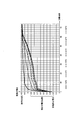
- FIG. 13 is a diagram showing the relationship between the charging time of the power supply and the voltage of the power supply.
- FIG. 14 is a diagram showing the temperature dependency of the relationship between the charging time of the power supply and the voltage of the power supply.
- FIG. 15 is a flowchart showing still another example of the control method by the control unit in the charge mode.
- Patent Documents 1 and 2 various controls regarding charging and / or discharging of a secondary battery are known.
- an electric circuit that does not have a communication terminal, a temperature sensor, and the like may be configured in order to realize miniaturization. From such a point of view, the techniques described in Patent Literatures 1 and 2 may not be applied to the flavor suction device as it is. Therefore, there is room for study on control of charge and discharge of the secondary battery in the flavor suction device.
- a battery unit for a flavor suction device includes a chargeable / dischargeable power source, a connection portion electrically connectable to an external charger, and a control unit that performs control at least on the power source.
- the control unit detects an abnormality based on the charging time until the value related to the remaining amount of the power turns from the first predetermined value to the second predetermined value during the charging process of the power supply.
- a method comprising: obtaining a value related to the remaining amount of power during charging of a chargeable / dischargeable power supply provided to a battery unit for a flavor suction device; Detecting an abnormality based on a charging time until the value related to the amount becomes from the first predetermined value to the second predetermined value.
- the manufacturer In chargeable and dischargeable power supplies, the manufacturer generally defines the allowable temperature range during charging. Therefore, it is not desirable to charge the power supply in an environment where the temperature of the power supply is too low or too high.
- the inventor of the present application is aware that the charging time until the value relating to the remaining amount of the power becomes from the first predetermined value to the second predetermined value during the charging process of the power supply depends on the temperature range of the environment where the power is placed It has been found that it can be used to estimate whether the temperature of the power supply during charging is within the allowable temperature range.
- abnormality detection can be performed without using a temperature sensor that measures the temperature of the power supply.
- a temperature sensor that measures the temperature of the power supply.
- Such a method can be suitably applied to a compact and portable flavor aspirator having an electronic circuit with a particularly simple configuration.
- FIG. 1 is an exploded view showing a flavor suction device according to an embodiment.
- FIG. 2 is a view showing an atomization unit according to an embodiment.
- FIG. 3 is a schematic view showing an example of the configuration of a suction sensor according to an embodiment.
- FIG. 4 is a block diagram showing the electrical configuration of the flavor suction device.
- FIG. 5 is a diagram showing an electric circuit of the battery unit.
- FIG. 6 is a diagram showing an electrical circuit of the atomization unit and the battery unit in a state where a load is connected.
- FIG. 7 is a diagram showing an electric circuit of the charger and the battery unit in a state where the charger is connected.
- the flavor suction device 100 may be a non-burning type flavor suction device for suctioning suction components (scent and taste components) without combustion.
- the flavor suction device 100 may have a shape extending along a predetermined direction A, which is a direction from the non-sucking end E2 to the sucking end E1.
- the flavor suction device 100 may include one end E1 having a suction port 141 for suctioning a suction component, and the other end E2 opposite to the suction port 141.
- the flavor suction device 100 may have a battery unit 110 and an atomization unit 120.
- the atomization unit 120 may be configured to be removable from the battery unit 110 via mechanical connection parts 111 and 121.
- a load 121R described later in the atomization unit 120 is a power supply provided to the battery unit 110 via the electrical connection terminal 110t. It is electrically connected to 10. That is, the electrical connection terminal 110 t constitutes a connection portion capable of electrically connecting and disconnecting the load 121 R and the power supply 10.
- the atomization unit 120 has a suction component source sucked by the user, and a load 121 R that vaporizes or atomizes the suction component source by the power from the power source 10.
- the aspiration component source may include an aerosol source that generates an aerosol, and / or a flavor source that generates a flavor component.
- the load 121R may be any device capable of generating an aerosol and / or a flavor component from an aerosol source and / or a flavor source by receiving power.
- the load 121R may be a heating element such as a heater or an element such as an ultrasonic wave generator.
- the heat generating element include a heat generating resistor, a ceramic heater, and a heater of an induction heating type.
- the atomization unit 120 may include a reservoir 121P, a wick 121Q, and a load 121R.
- the reservoir 121P may be configured to store a liquid aerosol source or a flavor source.
- the reservoir 121P may be, for example, a porous body made of a material such as a resin web.
- the wick 121Q may be a liquid holding member that draws in an aerosol source or a flavor source from the reservoir 121P using capillary action.
- the wick 121Q can be made of, for example, glass fiber or porous ceramic.
- the load 121R atomizes the aerosol source held by the wick 121Q or heats the flavor source.
- the load 121R is formed of, for example, a resistive heating element (for example, a heating wire) wound around the wick 121Q.
- the air flowing in from the inflow hole 122A passes near the load 121R in the atomization unit 120.
- the suction component generated by the load 121R flows with the air towards the suction port.
- the aerosol source may be liquid at ambient temperature.
- polyhydric alcohols can be used as an aerosol source.
- the aerosol source itself may have a flavor component.
- the aerosol source may include a tobacco material which releases flavoring ingredients by heating, or an extract derived from the tobacco material.
- the load 121R may be placed in contact with or in close proximity to a solid aerosol source to generate an aerosol from the solid aerosol source.
- the atomization unit 120 may include a replaceable flavor unit (cartridge) 130.
- the flavor unit 130 has a cylinder 131 containing a flavor source.
- the cylinder 131 may include the film member 133 and the filter 132.
- a flavor source may be provided in the space formed by the membrane member 133 and the filter 132.
- the atomization unit 120 may include the destruction unit 90.
- the destruction part 90 is a member for destroying a part of the membrane member 133 of the flavor unit 130.
- the destruction portion 90 may be held by a partition member 126 for separating the atomization unit 120 and the flavor unit 130.
- the partition member 126 is, for example, polyacetal resin.
- the breaking part 90 is, for example, a cylindrical hollow needle. By piercing the tip of the hollow needle into the membrane member 133, an air flow path is formed that allows the atomization unit 120 and the flavoring unit 130 to be in air communication.
- a mesh having a roughness that does not allow passage of the flavor source is provided inside the hollow needle.
- the flavor source in the flavor unit 130 imparts a flavor ingredient to the aerosol generated by the load 121 R of the atomization unit 120.
- the flavor imparted to the aerosol by the flavor source is carried to the mouth of the flavor suction device 100.
- the flavor suction device 100 may have multiple suction component sources.
- flavor aspirator 100 may have only one aspiration component source.
- the flavor source in the flavor unit 130 may be solid at normal temperature.
- the flavor source is constituted by a raw material piece of plant material that imparts a flavor and taste component to the aerosol.
- a raw material piece which comprises a flavor source the molded object which shape
- the flavor source may be a molded article obtained by forming the tobacco material into a sheet.
- the raw material piece which comprises a flavor source may be comprised by plants (for example, mint, herbs, etc.) other than tobacco.
- the flavor source may be provided with a flavor such as menthol.
- the flavor aspirator 100 may include a mouthpiece 142 having a suction port 141 for the user to aspirate the aspiration component.
- the mouthpiece 142 may be configured to be removable from the atomization unit 120 or the flavor unit 130, and may be configured to be integral and inseparable.
- the battery unit 110 may have a power supply 10, a notification unit 40, and a control unit 50.
- the power supply 10 stores the power necessary for the operation of the flavor suction device 100.
- the power source 10 may be removable from the battery unit 110.
- the power source 10 may be a rechargeable battery, such as, for example, a lithium ion secondary battery.
- the control unit 50 may have, for example, a control unit 51 such as a microcomputer, the suction sensor 20, and the push button 30. Furthermore, the flavor suction device 100 may include a voltage sensor 150. The control unit 51 performs various controls necessary for the operation of the flavor / suction device 100 according to the output value of the voltage sensor 150. For example, the control unit 51 may configure a power control unit that controls the power from the power supply 10 to the load 121.
- the load 121R provided in the atomization unit 120 is electrically connected to the power supply 10 of the battery unit 110 (see FIG. 6).
- the flavor suction device 100 may include a switch 140 capable of electrically connecting and disconnecting the load 121R and the power supply 10.
- the switch 140 is opened and closed by the control unit 50.
- the switch 140 may be configured of, for example, a MOSFET.
- the control unit 50 may include a demand sensor capable of outputting a signal requesting operation of the load 121R.
- the request sensor may be, for example, a push button 30 pressed by the user or a suction sensor 20 that detects a suction operation of the user.
- the control unit 50 acquires an operation request signal to the load 121R and generates a command for operating the load 121R.
- the control unit 50 outputs a command for operating the load 121R to the switch 140, and the switch 140 is turned on according to the command.
- the control unit 50 is configured to control the power supply from the power supply 10 to the load 121R. When power is supplied from the power supply 10 to the load 121R, the load 121R vaporizes or atomizes the suction component source.
- the suction sensor 20 may be configured to output an output value that fluctuates according to suction from the suction port. Specifically, the suction sensor 20 outputs a value (for example, a voltage value or a current value) that changes according to the flow rate of air drawn from the non-sucking side toward the suction side (that is, puff operation of the user). It may be a sensor that Such sensors include, for example, condenser microphone sensors and known flow sensors.
- FIG. 3 shows a specific example of the suction sensor 20.
- the suction sensor 20 illustrated in FIG. 3 includes a sensor body 21, a cover 22, and a substrate 23.
- the sensor body 21 is configured of, for example, a capacitor.
- the electric capacity of the sensor body 21 changes due to the vibration (pressure) generated by the air drawn from the air introduction hole 125 (that is, the air drawn from the non-suction side toward the suction side).
- the cover 22 is provided on the suction side with respect to the sensor body 21 and has an opening 22A. By providing the cover 22 having the opening 22A, the electric capacity of the sensor body 21 is easily changed, and the response characteristic of the sensor body 21 is improved.
- the substrate 23 outputs a value (here, a voltage value) indicating the electric capacitance of the sensor body 21 (capacitor).
- the flavor suction device 100 more specifically, the battery unit 110 may be configured to be connectable to a charger 200 that charges the power supply 10 in the battery unit 110 (see FIG. 7).
- the charger 200 When the charger 200 is connected to the battery unit 110, the charger 200 is electrically connected to the power supply 10 of the battery unit 110.
- the pair of electrical terminals 110t of the battery unit 110 for electrically connecting the charger 200 can also serve as the pair of electrical terminals of the battery unit 110 for electrically connecting the load 121R. That is, the charger 200 and the atomization unit 120 may be electrically connected to the same electrical terminal 110t of the battery unit.
- the charger 200 may be configured to be incapable of communicating with the control unit 50 of the battery unit 110. That is, the communication terminal for communicating between the processor 250 of the charger 200 and the control unit 50 is unnecessary.
- the battery unit 110 may have a determination unit that determines whether the charger 200 is connected.
- the determination unit may be, for example, a unit that determines the presence or absence of connection of the charger 200 based on a change in potential difference between the pair of electric terminals 110t to which the charger 200 is connected.
- the determination unit may include a pair of electric resistors 180 and 182 arranged in series.
- One of the pair of electric resistors 180 is provided at a position to connect the electric terminals 110t.
- the other 182 of the pair of electric resistors is connected to one terminal of the control unit 51.
- the electrical resistance values 180, 182 of the pair of electrical resistors may be known.
- the electrical resistance value of the pair of electrical resistors 180 and 182 may be sufficiently high, for example 10 k ⁇ , compared to the load 121R.
- the potentials at points between the pair of electric resistors 180 and 182 differ from each other in the case where nothing is connected to the electric terminal 110 t and in the case where the charger 200 is connected to the electric terminal 110 t. Therefore, the control unit 51 receives no signal from the other of the pair of electric resistors (hereinafter, referred to as "WAKE signal"), and thus nothing or connection is made to the connection unit 110t. It is possible to estimate one of the states in which the charger 200 is connected to the unit 110t.
- WAKE signal no signal from the other of the pair of electric resistors
- the determination part which determines the connection of the charger 200 is not limited to the said means, As long as the presence or absence of the connection of the charger 200 can be determined, what kind of means may be used. Preferably, as described above, it is preferable that at least one of the pair of electrical terminals 110 t also serve as a connection detection terminal of the charger 200.
- the battery unit 110 may have disconnecting means 170 that at least temporarily disable the electrical connection between the power supply 10 and the load 121R.
- the cutting means 170 may be provided between the power supply 10 and the electrical terminal 110 t in the electric circuit of the battery unit 110.
- the disconnecting means 170 is non-reversible so that the control unit 51 can not resume the power supply from the power supply 10 to the load 121R. It is preferable to be configured to be switchable to a second mode in which the second mode is disabled.
- the control unit 51 may be configured to be able to control the cutting means 170 in the first mode and the second mode.
- the cutting means 170 may include a fuse 172.
- the cutting means 170 may branch in parallel to the normal line L2 and the abnormal line L3 from the line L1 in which the fuse 172 is provided.
- the first electric resistor 174 and the first switch 175 may be connected in series with each other.
- the second electric resistor 176 and the second switch 177 may be connected in series with each other.
- both the first switch 175 and the second switch 177 are OFF, the power can not be supplied from the power supply 10 to the load 121R, and the power supply 10 can not be charged by the charger 200.
- the first switch 175 is ON, and the second switch 177 is OFF.
- the load 121R or the charger 200 connected to the connection unit 110t is connected to the power supply 10 through the normal line L2.
- both the first switch 175 and the second switch 177 are off. This temporarily disables the electrical connection between the power supply 10 and the load 121R or the charger 200.
- the first switch 175 and the second switch 177 are turned on.
- current flows through both the normal line L2 and the abnormal line L3, and a current larger than that during normal operation flows through the fuse 172, and as a result, the fuse 172 blows.
- the fuse 172 is melted, the electrical connection between the power supply 10 and the load 121R or the charger 200 is irreversibly disabled.
- the resistance value of the first electric resistor 174 and the resistance value of the second electric resistor 176 are set such that the fuse 172 is melted in the second mode without the fuse 172 being melted in the first mode. Just do it.
- the abnormal line L3 may be a so-called short circuit line which does not have the second resistor 176 and has only the lead wire resistance.
- the notification unit 40 issues a notification for notifying the user of various types of information.
- the notification unit 40 may be, for example, a light emitting element such as an LED. Instead of this, the notification unit 40 may be an element that generates a sound or a vibrator.
- FIG. 8 is a flow chart showing an example of a control method in the feeding mode of the flavor / suction device.
- the control flow shown in FIG. 8 is implemented by the control unit 51.
- the power supply mode is a mode in which power can be supplied from the power supply 10 to the load 121R.
- the feed mode can be implemented at least when the atomization unit 120 is connected to the battery unit 110.
- the control unit 51 may control to shift to the power feeding mode by detecting that the load 121R is connected to the connection unit 110t.
- Control unit 50 determines whether or not an operation request signal to load 121R is obtained in the power feeding mode (step S100).
- the operation request signal may be, for example, a signal acquired from the suction sensor 20 when the suction sensor 20 detects a suction operation of the user. That is, the control unit 50 may turn on the switch 140 when the suction sensor 20 detects the suction operation of the user (step S106).
- the operation request signal may be a signal obtained from the push button 30 when it is detected that the push button 30 is pressed. That is, the control unit 50 may turn on the switch 140 when detecting that the user has pressed the push button (step S106).
- the control unit 50 acquires the voltage of the power supply 10 before turning on the switch 140 as necessary (step S102). It is preferable that the voltage of the power supply 10 determine the pulse width (predetermined time) for one pulse of the power supplied to the load 121R based on the acquired power (step S104).
- the pulse width may be, for example, in the range of 50 to 200 msec.
- the control unit 50 turns off the switch 140 (step S110) after a lapse of time corresponding to the pulse width (predetermined time) (step S108). Thereby, a voltage is applied to the load 121R for the pulse width of one pulse.
- the control unit 50 determines whether the end timing of the power supply to the load 121R has been detected (step S114). When the control unit 50 detects the end timing, the control unit 50 ends the power supply to the load 121R (step S116).
- the end timing of the power supply to the load 121R may be, for example, the timing when the suction sensor 20 detects the end of the operation for using the load 121R. Instead of this, the end timing of the power supply to the load 121R may be the timing at which the release of the pressing of the push button 30 is detected. Furthermore, the end timing of the power supply to the load 121R may be a timing when it is detected that a predetermined cutoff time has elapsed from the start of the power supply to the load 121R.
- the predetermined cut-off time may be preset based on the time required for a general user to perform one suction operation. For example, the predetermined cutoff time may be in the range of about 2 to 5 seconds.
- control unit 50 When the control unit 50 does not detect the end timing of the power supply to the load 121R, the control unit 50 turns on the switch 140 again to supply the power (next power pulse) to the load 121R (steps S106, S108, S110). By repeatedly supplying power for one pulse to the load 121R, power for one puff operation can be supplied to the load 121R.
- FIG. 9 is a graph showing an example of control of the amount of power supplied from the power supply 10 to the load 121R.
- FIG. 9 shows the relationship between the output value of the suction sensor 20 and the voltage supplied to the load 121R.
- the suction sensor 20 may be configured to output an output value that fluctuates according to suction from the suction port 141.
- the output value of the suction sensor 20 may be a value corresponding to the flow rate of the gas in the flavor / aspirator (pressure change in the flavor / aspirator) as shown in FIG. 9, but is not limited thereto.
- the control unit 50 may be configured to detect suction according to the output value of the suction sensor 20.
- the control unit 50 may be configured to detect the suction operation by the user when the output value of the suction sensor 20 becomes equal to or more than the first predetermined value O1. Therefore, the control unit 50 may determine that the operation request signal to the load 121R is acquired when the output value of the suction sensor 20 becomes equal to or more than the first predetermined value O1 (step S100).
- the control unit 50 may determine that the end timing of the power supply to the load 121R has been detected (step S114).
- the period from the start of the power supply to the load 121R to the end of the power supply to the load 121R may vary depending on the manner of the suction operation by the user. Even in this case, however, the power supply to the load 121R may be terminated when the predetermined cutoff time described above has elapsed after the operation request signal to the load 121R is acquired.
- control unit 50 may be configured to detect suction only when the absolute value of the output value of the suction sensor 20 is equal to or greater than a first predetermined value (predetermined threshold) O1. As a result, it is possible to suppress the load 121R from operating erroneously due to the noise of the suction sensor 20. Further, the second predetermined value O2 for detecting the end timing of the power supply to the load 121R may be smaller than the first predetermined value O1.
- the control unit 51 may adjust the amount of power supplied from the power supply 10 to the load 121R by pulse width control.
- the duty ratio for the pulse width may be less than 100%.
- the control unit 51 narrows the pulse width supplied to the load 121R (see the middle graph in FIG. 9). For example, when the voltage value of the power supply 10 is relatively low, the control unit 51 widens the pulse width supplied to the load 121R (see the lower graph in FIG. 9).
- the setting of the pulse width can be performed in step S104 described above.
- control unit 51 is preferably configured to control the voltage applied to the load 121R by pulse width modulation having a larger duty ratio as the voltage value of the power supply 10 decreases.
- the control unit 51 controls the duty ratio of pulse width modulation so that the amount of power per pulse supplied to the load 121R is constant regardless of the voltage of the power supply 10.
- FIG. 10 is a flowchart showing an example of charge control by the charger 200. The control flow shown in FIG. 10 is performed by the processor mounted on the charger 200.
- the charger 200 determines whether or not the battery unit 110 is connected, and stands by until the battery unit 110 is connected (step S300).
- the connection between the charger 200 and the battery unit 110 can be detected by a known method.
- the charger 200 can determine whether or not the battery unit 110 is connected by detecting a change in voltage between a pair of electrical terminals for connecting the charger 200 to the battery unit 110.
- the charger 200 determines whether the power supply 10 is deeply discharged (step S302).
- deep discharge of the power supply 10 means a state in which the voltage of the power supply 10 is less than the deep discharge determination voltage lower than the discharge termination voltage.
- the deep discharge determination voltage may be, for example, in the range of 3.1 V to 3.2 V.
- the charger 200 can use a voltmeter provided in the charger 200 to estimate the voltage of the power supply 10.
- the charger 200 can determine whether the power supply 10 is deeply discharged by comparing the estimated value of the voltage of the power supply 10 with the deep discharge determination voltage.
- the charger 200 charges the power supply 10 with low-rate power (step S304). As a result, the charger 200 can restore the power supply 10 from the deep discharge state to a state of a voltage higher than the discharge termination voltage.
- the charger 200 determines whether the voltage of the power supply 10 is equal to or higher than the switching voltage (step S306).
- the switching voltage is a threshold for dividing a section of constant current charging (CC charging) and a section of constant voltage charging (CV charging).
- the switching voltage may be, for example, in the range of 4.0V to 4.1V.
- the charger 200 charges the power supply 10 by a constant current charging method (step S308). If the voltage of the power supply 10 is equal to or higher than the switching voltage, the charger 200 charges the power supply 10 by a constant voltage charging method (step S310). In the constant voltage charging method, charging progresses and charging current decreases.
- the charger 200 determines whether the charging current is less than or equal to a predetermined charging completion current (step S312).
- the charging current can be acquired by an ammeter provided in the charger 200. If the charging current is larger than the predetermined charging completion current, charging of the power supply 10 is continued by the constant voltage charging method.
- the charger 200 determines that the power supply 10 is fully charged, and stops charging (step S314).
- FIG. 11 is a flowchart showing an example of a control method by the control unit in the charge mode.
- the charge mode is a mode in which the power supply 10 can be charged.
- the control unit 51 performs processing of determining the deterioration of the power supply 10 using the accumulated value of the connection time to the charger.
- control unit 51 detects connection of the charger 200 to the battery unit 110 (step S400).
- the connection of the charger 200 to the battery unit 110 can be detected by acquiring a change in voltage between the pair of electrical terminals 110t, as described above.
- the second timer is set to 0 (step S404).
- the second timer measures the connection time to the charger 200 for one charge.
- control unit 51 turns on the switch 140 (step S406). Thereby, the charger 200 and the power supply 10 are electrically connected to each other. Therefore, charging of the power supply 10 is started.
- the control unit 51 turns on the first timer and the second timer (steps S408 and S410). As a result, the measured values of the first timer and the second timer start to increase.
- the first timer measures an accumulated value of connection time to the charger. Therefore, the first timer is set to 0 in a new battery unit.
- the first timer may be configured to be reset to 0 when the power supply 10 is replaced. That is, the first timer may be configured to measure an accumulated value of connection time to the charger 200 with respect to a certain power supply 10.
- the control unit 51 turns the switch off (steps S412 and S414).
- the predetermined time lapse is not particularly limited, it may be, for example, 80 msec to 120 msec.
- the control unit 51 preferably stops the first timer and the second timer (steps S416 and S418). That is, it is preferable that the first timer and the second timer be stopped while the power supply 10 and the charger 200 are electrically disconnected inside the battery unit.
- the control unit 51 determines whether the value of the first timer has exceeded the first predetermined time (step S420).
- the first predetermined time may be a time preset according to the design of the battery unit. Specifically, the first predetermined time may be set based on the charging time to such an extent that the battery unit is judged to be deteriorated. In the present embodiment, the first predetermined time may be, for example, 500 to 1000 hours.
- the control unit 51 determines that the power supply 10 has deteriorated (step S422). That is, when the accumulated value of the connection time to the charger 200 exceeds the first predetermined time, the control unit 51 determines that the power supply 10 has deteriorated.
- the control unit 51 preferably stops using the power supply 10 (step S424). For example, when the accumulated value of the connection time to the charger 200 exceeds the first predetermined time, the control unit 51 turns off the switch 140 to force charging, even if the charger 200 is attached to the battery unit 110. Keep it stopped. As a result, it is possible to prevent further charging 10 of the power supply 10 determined to be deteriorated.
- control unit 51 may blow the fuse 172 by switching the cutting means 170 to the second mode when the accumulated value of the connection time to the charger 200 exceeds the first predetermined time.
- the control unit 51 may notify the user that the power supply 10 is deteriorated by light, sound or vibration from the notification unit 40.
- the pattern of light, sound or vibration from the notification unit 40 for notifying that the power supply 10 has deteriorated is different from the pattern of light, sound or vibration from the notification unit 40 at normal times.
- the light, sound or vibration pattern from the notification unit 40 for notifying that the power supply 10 has deteriorated is the light from the notification unit 40 when the value of the second timer exceeds a second predetermined time described later. Preferably, it differs from the sound or vibration pattern.
- step S420 when the value of the first timer does not exceed the first predetermined time, the control unit 51 determines whether the end of charging has been detected (step S426).
- the detection of the end of charging is performed, for example, by detecting that the connection of the charger 200 is released. Further, the detection of the end of charging may be performed, for example, by detecting that the charging current from the charger 200 is stopped.
- the control unit 51 stops the charge with the switch 140 turned off (step S430).
- the control unit 51 determines whether the value of the second timer exceeds a second predetermined time (step S428).
- the second predetermined time may be set based on the time required to charge the power supply 10 whose charge capacity has decreased to the discharge termination voltage to the full charge voltage.
- the second predetermined time is a time shorter than the first predetermined time.
- the second predetermined time may be set to an appropriate value which has been found by experiments in advance according to the design of the power supply 10.
- the second predetermined time may be, for example, 60 to 120 minutes.
- the control unit 51 stops charging of the power supply 10 while the switch 140 is turned off (step S430). Specifically, when the value of the second timer exceeds the second predetermined time, the control unit 51 forcibly stops charging even if the charger 200 is attached to the battery unit 110. Thus, the control unit 51 can prevent overcharging of the power supply 10.
- the control unit 51 may stop charging of the power supply 10 and notify the user of the stop of charging by light, sound or vibration from the notification unit 40.
- the light, sound or vibration pattern from the notification unit 40 for notifying the stop of the charging is the light, sound or vibration of the notification unit 40 for notifying that the power supply 10 has deteriorated as described above. It is preferable to be different from the pattern.
- control unit 51 keeps the count to the accumulated value of the connection time to the charger, that is, the first timer stopped.
- the control unit 51 turns on the switch 140 again after the predetermined time has elapsed, and repeats charging of the power supply 10 (steps S432 and S406).
- the predetermined time may be, for example, 300 ⁇ sec to 500 ⁇ sec.
- the predetermined time may be a preset fixed value.
- control unit 51 When the switch 140 is turned on, the control unit 51 turns on the first timer and the second timer as described above (steps S408 and S410). As a result, the measured values of the first timer and the second timer start to increase again. As described above, the control unit 51 is configured to count the accumulated value of the connection time to the charger 200 while the switch 140 is in the ON state.
- control unit 51 periodically stops charging of the power supply. For example, the control unit 51 repeats the process of charging for 80 msec to 120 msec and stopping charging for example for 300 ⁇ sec to 500 ⁇ sec.
- control unit 51 measure the accumulated value of the connection time to the charger 200 without including the period in which the charging is periodically stopped. That is, the first timer may be stopped during a period in which charging is periodically stopped. Similarly, the second timer may also be stopped during the period when charging is periodically stopped.
- control unit 51 may forcibly stop charging of the power supply 10 by electrically disconnecting within the battery unit 110.
- the control unit 51 preferably stops counting of the first timer and / or the second timer. That is, in the state where charger 200 is connected to battery unit 110 and controller 200 is in the state where charger 200 and power source 10 are electrically connected to each other in battery unit 110, control unit 51 first timer and / or Alternatively, it is preferable to measure the connection time with a second timer.
- two timers ie, a first timer and a second timer
- steps S408 and S416 shown in FIG. 11 are unnecessary, and the accumulated value of the connection time to the charger 200 may be measured using the measurement value of the second timer. Since the second timer can measure the time taken for one charging process, the accumulated value of the connection time to the charger 200 is measured by accumulating the measured value of the second timer for each charging process. be able to.
- connection time (the value of the second timer) elapsed in the current charging process is added to the accumulated value of the connection time for the charger 200 accumulated in the previous charging process.
- the accumulated value (T1) of the connection time to the charger 200 can be calculated.
- Deterioration of the power supply 10 can be determined.
- the accumulated value (T1) of the connection time to the charger 200 exceeds the first predetermined time during the charging process, it is determined that the power supply 10 has deteriorated. It is preferable to stop the charging of the power supply. This can prevent the charging operation from being performed on the deteriorated power supply 10.
- FIG. 12 is a flowchart showing another example of the control method by the control unit in the charge mode.
- FIG. 13 is a diagram showing the relationship between the charging time of the power supply and the voltage of the power supply.
- FIG. 14 is a diagram showing the temperature dependency of the relationship between the charging time of the power supply and the voltage of the power supply.
- a power supply 10 such as a lithium ion secondary battery defines an allowable temperature range of the power supply during charging.
- the allowable temperature range varies depending on the type of the power supply 10, but may be defined, for example, in the range of 0 to 45.degree.
- the control unit 51 detects a temperature abnormality of the power supply 10 based on the voltage of the power supply 10 during the charging process of the power supply 10.
- the control unit 51 detects connection of the charger 200 to the battery unit 110 (step S400).
- the control unit 51 obtains the voltage (V batt ) of the power supply 10 (step S401).
- the voltage of the power supply 10 is preferably an open circuit voltage (OCV) obtained without the power supply 10 and the charger 200 being electrically connected.
- the lower limit value (first predetermined value) of the predetermined voltage range will be described later.
- the third timer measures the time required for the voltage of the power supply 10 to reach a second predetermined value from a first predetermined value described later during charging.
- control unit 51 turns on the switch 140 (step S406). Thereby, the charger 200 and the power supply 10 are electrically connected to each other. Therefore, charging of the power supply 10 is started.
- the control unit 51 turns on the third timer (step S411). Thereby, the measurement value of the third timer starts to increase.
- the control unit 51 turns the switch off (steps S412 and S414).
- the predetermined time lapse is not particularly limited, it may be, for example, 80 msec to 120 msec.
- the control unit 51 stops the third timer (step S419). That is, the third timer may be stopped while the power supply 10 and the charger 200 are electrically disconnected inside the battery unit.
- the control unit 51 acquires the voltage of the power supply 10 in a state in which the switch 140 is turned off (step S440).
- the voltage of the power supply 10 can be acquired by the voltage sensor 150.
- the voltage of the power supply 10 is preferably an open circuit voltage (OCV) obtained without the power supply 10 and the charger 200 being electrically connected.
- the voltage of the power supply 10 may be a closed circuit voltage (CCV) obtained in a state where the power supply 10 and the charger 200 are electrically connected. In this case, the voltage of the power supply 10 is acquired before the switch 140 is turned off in step S414.
- the voltage of the power supply 10 is defined by the open circuit voltage (OCV) rather than the closed circuit voltage (CCV) in order to eliminate the influence of voltage drop and internal resistance or temperature change. Is preferred.
- the voltage of the power supply 10 is defined by the open circuit voltage (OCV) rather than the closed circuit voltage (CCV) in order to eliminate the influence of voltage drop and internal resistance or temperature change. Is preferred.
- the control unit 51 detects the end of charging, as in step S426 of FIG. 11, the control unit 51 forcibly switches the switch 140, for example. You may stop charging.
- the first predetermined value may be in the range from the discharge termination voltage to a voltage about 0.1 V higher than the discharge termination voltage.
- the first predetermined value is a discharge termination voltage.
- the control unit 51 turns on the switch 140 again after the predetermined time has elapsed, and repeats charging of the power supply 10 (steps S442 and S406).
- the predetermined time may be, for example, 300 ⁇ sec to 500 ⁇ sec.
- the predetermined time may be a preset fixed value.
- the control unit 51 resets the third timer and restarts the timer (step S446).
- step S450 control unit 51 determines whether or not the voltage of power supply 10 is equal to or higher than the upper limit value (second predetermined value) of the predetermined voltage range (step S450).
- the second predetermined value is larger than the first predetermined value described above and smaller than the full charge voltage.
- the second predetermined value is preferably smaller than the switching voltage described above.
- the second predetermined value may be, for example, in the range of 3.8V to 4.0V.
- control unit 51 turns on the switch 140 again after the elapse of the predetermined time described above, and repeats charging of the power supply 10 (steps S450 and S406). .
- the control unit 51 ends the measurement of the time by the third timer (step S454).
- the third timer measures the charging time until the voltage of the power supply 10 reaches the upper limit (the second predetermined value) from the lower limit (the first predetermined value) of the predetermined voltage range.
- control unit 51 determines whether the value of the third timer is equal to or less than a third predetermined time (step S456). That is, control unit 51 determines whether the charging time until the voltage of power supply 10 reaches the upper limit (the second predetermined value) from the lower limit (the first predetermined value) of the predetermined voltage range is the third predetermined time or less. to decide.
- the third predetermined time will be described later.
- the control unit 51 If the charging time until the voltage of the power supply 10 reaches the lower limit value (first predetermined value) of the predetermined voltage range to the upper limit value (second predetermined value) is equal to or less than the third predetermined time, the control unit 51 is abnormal To detect Specifically, the control unit 51 determines that the temperature of the power supply 10 is abnormal, in particular, the temperature of the power supply 10 is below the allowable temperature range, and stops the charging process of the power supply 10 (steps S458 and S460).
- Stopping the charging process may be, for example, a forced stop or restriction of charging by the control unit 51. Forced stop or restriction of charging can be realized by disconnecting the electrical connection between the power supply 10 and the charger 200 in the battery unit 110.
- the control unit 51 may turn off the switch 140 to disconnect the electrical connection.
- the disconnection of the electrical connection may be made by switching the disconnecting means 170 into the first mode, temporarily disabling the electrical connection between the charger 200 and the power supply 10.
- the control unit 51 may notify the user of the abnormality through the notification unit 40. Specifically, the control unit 51 may notify the user of the abnormality by light, sound or vibration from the notification unit 40.
- the pattern of light, sound or vibration from the notification unit 40 at this time is the pattern of light, sound or vibration from the notification unit 40 at the normal time, and for notifying deterioration of the power supply 10 in the control flow shown in FIG. It is preferable to be different from the pattern.
- the control unit 51 It is determined that the temperature is within the normal range, the switch 140 is turned on again, and charging of the power supply 10 is repeated (steps S462 and S406).
- the control unit 51 controls the voltage of the power supply 10 to change from the lower limit (first predetermined value) of the predetermined voltage range to the upper limit (second predetermined value) during the charging process of the power supply 10. Detects abnormalities based on charging time.
- the control unit 51 is configured to periodically stop the charging of the power supply 10 (step S414), and the control unit 51 periodically stops the charging as shown in the above-described flow. It is preferable to measure the charging time without including a period. Instead of this, the control unit 51 may measure the charging time including the period in which the charging is periodically stopped.
- the value of the second flag (F2) is set based on the voltage of the power supply 10 acquired when the charging mode is started (steps S401, S402, S403a and S403b).
- the third timer is configured to measure time from when the voltage of the power supply 10 exceeds the lower limit of the predetermined voltage range to when the upper limit of the predetermined voltage range is reached. Therefore, steps S402, S444, and S446 regarding the first flag (F1) for determining the timing at which the voltage of the power supply 10 exceeds the lower limit value of the predetermined voltage range are provided.
- the temperature of the power supply 10 can be determined in step S456 using the second timer shown in FIG. That is, it is possible to implement a control flow of determining the temperature abnormality of the power supply 10 using the above-mentioned second timer instead of the third timer shown in FIG.
- step S304 the charger 200 charges the power supply 10 with a low rate power (step S304), so the charge period at the low rate is not counted during the measurement time by the third timer. It is preferable to execute steps S402 and S442 to 448 shown in FIG.
- control unit 51 charges the battery 10 until the voltage of the power supply 10 reaches the upper limit (the second predetermined value) from the lower limit (the first predetermined value) of the predetermined voltage range during the charging process of the power supply 10. Detect anomalies based on time.
- the control unit 51 can also detect an abnormality using a value related to the remaining amount of the power supply 10 instead of the voltage of the power supply.
- control unit 51 causes the remaining capacity or charging rate (SOC) of the power supply 10 to reach the upper limit (second predetermined value) from the lower limit (first predetermined value) of the predetermined range during the charging process of the power supply 10
- the temperature abnormality of the power supply 10 may be detected based on the charging time of In this case, instead of acquiring the voltage of the power supply 10 in step S440 described above, the control unit 51 may acquire a value regarding the remaining amount of the power supply 10, for example, the remaining capacity or the charging rate.
- the first predetermined value is in a range from a value related to the remaining amount of the power supply 10 corresponding to the discharge termination voltage to a value related to the remaining amount of the power supply 10 corresponding to a voltage about 0.1 V higher than the discharge termination voltage. May be there.
- the first predetermined value is a value related to the remaining amount of the power supply 10 corresponding to the discharge termination voltage.
- the second predetermined value is larger than the first predetermined value described above and smaller than the value regarding the remaining amount of the power supply 10 corresponding to the full charge voltage.
- the second predetermined value is preferably smaller than the value relating to the remaining amount of the power supply 10 corresponding to the switching voltage described above.
- the second predetermined value may be, for example, within the range of the value regarding the remaining amount of the power supply 10 corresponding to 3.8V to 4.0V.
- the remaining capacity or charging rate (SOC) of the power source 10 can be obtained by any known method.
- the remaining capacity or state of charge (SOC) of the power supply 10 has a correlation with the voltage of the power supply 10. Therefore, the remaining capacity or charging rate (SOC) of the power supply 10 can be estimated based on the voltage of the power supply 10 using the correlation between the remaining capacity or charging rate (SOC) of the power supply 10 and the voltage of the power supply 10. That is, the control unit 51 may acquire the voltage of the power supply 10 during a period in which charging of the power supply 10 is periodically stopped, and derive a value related to the remaining amount of the power supply 10 based on the acquired voltage of the power supply 10 .
- the correlation between the remaining capacity or charging rate (SOC) of the power source 10 and the voltage of the power source 10 is determined according to the design of the power source 10, and thus can be determined in advance by experiment.
- the charging time until the value related to the remaining amount of the power supply 10 reaches the upper limit (the second predetermined value) from the lower limit (the first predetermined value) of the predetermined range during the charging process of the power supply 10 is the third predetermined time or less In the case where the temperature of the power supply 10 is abnormal.
- the third predetermined time can detect a temperature lower than the allowable temperature range of the power supply 10 according to the lower limit (first predetermined value) and the upper limit (second predetermined value) of the predetermined range. It is set.
- the third predetermined time can be set to a predetermined value by experiment in advance if the lower limit (first predetermined value) and the upper limit (second predetermined value) of the predetermined range are determined.
- the third predetermined time is a time shorter than the first predetermined time and the second predetermined time described above.
- FIG. 14 shows experimental data obtained in a lithium ion secondary battery. Taking into account some errors or buffers in the allowable temperature range of various types of lithium ion secondary batteries, it may be regarded as a temperature abnormality of the power supply, for example, when the temperature of the power supply 10 is 4 ° C or less, preferably 0 ° C or less .
- the first predetermined value is defined by the discharge termination voltage (3.2 V) and the second predetermined value is defined by 3.9 V, according to the graph shown in FIG. It may be from minutes to 12 minutes.
- FIG. 15 is a flowchart showing still another example of the control method by the control unit in the charge mode.
- FIG. 13 shows another method for detecting the temperature abnormality of the power supply 10 during charging described with reference to FIG. 12.
- the steps from step S400 to step S448 are as described above, and the description thereof is omitted (see FIG. 12).
- step S451 is performed instead of step S450 shown in FIG.
- the control unit 51 determines whether the value of the third timer exceeds a third predetermined time (step S451).
- the third timer counts the time elapsed from when the voltage of the power supply 10 reaches the lower limit value of the predetermined voltage range. Therefore, in step S451, it is determined whether the third predetermined time has elapsed starting from when the voltage of the power supply 10 reaches the lower limit value of the predetermined voltage range.
- the third predetermined time may be the same as that described in FIG.
- control unit 51 may continue charging of the power supply 10 by turning on the switch 140 (step S406).
- the control unit 51 ends the measurement of the time by the third timer (step S454).
- the control unit 51 determines whether the voltage (V batt ) of the power supply 10 is equal to or higher than the upper limit value (second predetermined value) of the predetermined voltage range (step S457).
- the upper limit value (second predetermined value) of the predetermined voltage range is as described above.
- the second predetermined value is preferably smaller than the switching voltage described above, and may be, for example, in the range of 3.8 V to 4.0 V.
- the control unit 51 detects an abnormality. Specifically, the control unit 51 determines that the temperature of the power supply 10 is abnormal, in particular, the temperature of the power supply 10 is below the allowable temperature range, and stops the charging process of the power supply 10 (steps S458 and S460).
- the control unit 51 determines that the predetermined charging time has elapsed.
- the temperature abnormality of the power supply can be detected based on the voltage of the power supply 10.
- the control unit 51 can also detect an abnormality using a value related to the remaining amount of the power supply 10 instead of the voltage of the power supply. For example, when the value related to the remaining amount of the power supply 10 becomes the lower limit value (the first predetermined value) of the predetermined range during the charging process of the power supply 10, the control unit 51 The temperature abnormality of the power supply can be detected based on the value regarding the remaining amount. In this case, as described above, the value relating to the remaining amount of the power supply 10 may be, for example, the remaining capacity or charging rate (SOC) of the power supply 10.
- SOC remaining capacity or charging rate
- the voltage of the power supply 10 that is, the charging rate (SOC) of the power supply 10 increases significantly in a predetermined charging period. Therefore, by the above-described method, it is possible to detect a temperature abnormality of the power supply 10 during charging without using a temperature sensor.
- the control unit 51 can execute the above-described flows shown in FIGS. 8, 11, 12 and 15. That is, the control unit 51 may have a program that causes the battery unit 110 and / or the flavor suction device 100 to execute the above-described method, and a storage medium in which the program is stored. Further, the aforementioned flow shown in FIG. 10 can be performed by the external charger 200. That is, the external charger 200 may have a program that causes a system including the flavor suction device 100 and the charger 200 to execute the above-described method, and a storage medium in which the program is stored.
- control 1 by control unit in charge mode and “control 2 by control unit in charge mode” have been described as different aspects.
- control 1 and 2 by the control unit in charge mode may be performed simultaneously in parallel.
Abstract
Description
特許文献1,2に記載されているように、二次電池の充電及び/又は放電に関する各種の制御が知られている。しかしながら、香味吸引器では、小型化を実現するために、通信端子や温度センサ等を有しない電気回路が構成されることがある。このような観点から、特許文献1,2に記載された技術をそのまま香味吸引器に適用できないことがある。したがって、香味吸引器における二次電池の充放電に関する制御について検討の余地が残されている。
以下において、一実施形態に係る香味吸引器について説明する。図1は、一実施形態に係る香味吸引器を示す分解図である。図2は、一実施形態に係る霧化ユニットを示す図である。図3は、一実施形態に係る吸引センサの構成の一例を示す模式図である。図4は、香味吸引器の電気的構成を示すブロック図である。図5は、バッテリユニットの電気回路を示す図である。図6は、負荷が接続された状態の霧化ユニット及びバッテリユニットの電気回路を示す図である。図7は、充電器が接続された状態の充電器及びバッテリユニットの電気回路を示す図である。
図8は、香味吸引器の給電モードにおける制御方法の一例を示すフローチャートである。図8に示す制御フローは、制御部51によって実施される。給電モードは、電源10から負荷121Rへ給電可能なモードである。給電モードは、少なくともバッテリユニット110に霧化ユニット120が接続されている場合に実施可能である。制御部51は、接続部110tに負荷121Rが接続されたことを検知することによって、給電モードに移行するよう制御してもよい。
図10は、充電器200による充電制御の一例を示すフローチャートである。図10に示す制御フローは、充電器200に搭載されたプロセッサにより行われる。
図11は、充電モードにおける制御部による制御方法の一例を示すフローチャートである。充電モードは、電源10の充電が可能なモードである。本例に係るフローチャートでは、制御部51、充電器に対する接続時間の累積値を用いて、電源10の劣化を判定する処理を行う。
図12は、充電モードにおける制御部による制御方法の別の一例を示すフローチャートである。図13は、電源の充電時間と電源の電圧との関係を示す図である。図14は、電源の充電時間と電源の電圧との関係の温度依存性を示す図である。
図15は、充電モードにおける制御部による制御方法のさらに別の一例を示すフローチャートである。図12を用いて説明した充電中の電源10の温度異常を検出するための別の方法を示している。本態様において、ステップS400~S448までのステップは、前述したとおりであり、その説明を省略する(図12参照)。
図8、図11、図12及び図15に示された前述のフローは、制御部51が実行することができる。すなわち、制御部51は、バッテリユニット110及び/又は香味吸引器100に前述の方法を実行させるプログラム、及び当該プログラムが格納された記憶媒体を有していてよい。さらに、図10に示された前述のフローは、外部充電器200が実行することができる。すなわち、外部充電器200は、香味吸引器100と充電器200とを含むシステムに前述の方法を実行させるプログラム、及び当該プログラムが格納された記憶媒体を有していてよい。
本発明は上述した実施形態によって説明したが、この開示の一部をなす論述及び図面は、この発明を限定するものであると理解すべきではない。この開示から当業者には様々な代替実施形態、実施例及び運用技術が明らかとなろう。
Claims (17)
- 充放電可能な電源と、
外部の充電器と電気的に接続可能な接続部と、
少なくとも前記電源に関する制御を行う制御部と、を有し、
前記制御部は、前記電源の充電処理中に前記電源の残量に関する値が第1所定値から第2所定値になるまでの充電時間に基づいて異常の検知をする、香味吸引器用のバッテリユニット。 - 前記制御部は、前記充電時間が第3所定時間以下だった場合に、異常の検知をする、請求項1に記載のバッテリユニット。
- 前記第1所定値は、前記電源の放電終止電圧に相当する前記電源の残量に関する値である、請求項1又は2に記載のバッテリユニット。
- 前記制御部は、前記異常を検知したときに、前記電源の充電処理を停止する、請求項1から3のいずれか1項に記載のバッテリユニット。
- 前記制御部は、前記電源への充電を定期的に停止するよう構成されており、
前記制御部は、前記電源への充電を定期的に停止している期間に前記電源の電圧を取得し、取得した前記電源の電圧に基づき前記電源の残量に関する値が前記第2所定値になったかどうか判断する、請求項1から4のいずれか1項に記載のバッテリユニット。 - 前記接続部に接続された前記充電器と前記電源との間の電気的な接続をON/OFFするスイッチを有し、
前記制御部は、前記スイッチをOFFにした状態で前記電源の電圧を取得する、
請求項5に記載のバッテリユニット。 - 前記制御部は、前記電源への充電を定期的に停止するよう構成されており、
前記制御部は、充電を定期的に停止した期間を含めることなく、前記充電時間を計測する、請求項1から6のいずれか1項に記載のバッテリユニット。 - 前記接続部は一対の電気端子を有し、
前記一対の電気端子のうちの少なくとも一方は、前記充電器の接続検知用の端子を兼ねる、請求項1から7のいずれか1項に記載のバッテリユニット。 - 前記接続部は、エアロゾル源又は香味源を気化又は霧化するための負荷と電気的に接続可能に構成されている、請求項1から8のいずれか1項に記載のバッテリユニット。
- 前記異常を検知したときに、光、音又は振動を発する通知部を有する、請求項1から9のいずれか1項に記載のバッテリユニット。
- 前記電源の残量に関する値は前記電源の電圧である、請求項1から10のいずれか1項に記載のバッテリユニット。
- 充放電可能な電源と、
外部の充電器と電気的に接続可能な接続部と、
少なくとも前記電源に関する制御を行う制御部と、を有し、
前記制御部は、前記電源の充電処理中に前記電源の残量に関する値が第1所定値になったときから既定の充電時間経過したときの前記電源の残量に関する値に基づいて異常の検知をする、香味吸引器用のバッテリユニット。 - 請求項1から12のいずれか1項に記載のバッテリユニットと、
前記バッテリユニットの前記電源に電気的に接続可能に構成され、エアロゾル源又は香味源を気化又は霧化するための負荷と、を含む香味吸引器。 - 請求項1から12のいずれか1項に記載のバッテリユニットに接続可能な充電器。
- 香味吸引器用のバッテリユニットに備えられた充放電可能な電源の充電処理中に、前記電源の残量に関する値を取得するステップと、
前記電源の充電処理中に前記電源の残量に関する値が第1所定値から第2所定値になるまでの充電時間に基づいて異常の検知をするステップと、を有する、方法。 - 香味吸引器用のバッテリユニットに備えられた充放電可能な電源の充電処理中に、前記電源の残量に関する値を取得するステップと、
前記電源の充電処理中に前記電源の残量に関する値が第1所定値になったときから既定の充電時間経過したときの前記電源の残量に関する値に基づいて異常の検知をするステップと、を有する、方法。 - 請求項15又は請求項16に記載の方法をバッテリユニットに実行させるプログラム。
Priority Applications (9)
| Application Number | Priority Date | Filing Date | Title |
|---|---|---|---|
| PCT/JP2017/037759 WO2019077712A1 (ja) | 2017-10-18 | 2017-10-18 | バッテリユニット、香味吸引器、バッテリユニットを制御する方法、及びプログラム |
| EP17929326.1A EP3698660A4 (en) | 2017-10-18 | 2017-10-18 | BATTERY UNIT, AROMA INHALER, BATTERY UNIT CONTROL PROCESS, AND PROGRAM |
| KR1020207011325A KR102406156B1 (ko) | 2017-10-18 | 2017-10-18 | 배터리 유닛, 향미 흡인기, 배터리 유닛을 제어하는 방법, 및 프로그램 |
| EA202090951A EA202090951A1 (ru) | 2017-10-18 | 2017-10-18 | Батарейный блок, устройство для вдыхания ароматизирующего вещества, способ управления батарейным блоком и программа |
| CA3079160A CA3079160C (en) | 2017-10-18 | 2017-10-18 | Battery unit, flavor inhaler, method for controlling battery unit, and program |
| JP2019549060A JP6936329B2 (ja) | 2017-10-18 | 2017-10-18 | バッテリユニット、香味吸引器、バッテリユニットを制御する方法、及びプログラム |
| CN201780096024.3A CN111225574B (zh) | 2017-10-18 | 2017-10-18 | 电池单元、香味吸入器、充电器、控制电池单元的方法以及计算机可读取的记录介质 |
| TW106137760A TWI732965B (zh) | 2017-10-18 | 2017-11-01 | 電池單元、香味吸嚐器、充電器、電源之異常檢測方法及電腦程式產品 |
| US16/849,566 US20200237009A1 (en) | 2017-10-18 | 2020-04-15 | Battery unit, flavor inhaler, method for controlling battery unit, and program |
Applications Claiming Priority (1)
| Application Number | Priority Date | Filing Date | Title |
|---|---|---|---|
| PCT/JP2017/037759 WO2019077712A1 (ja) | 2017-10-18 | 2017-10-18 | バッテリユニット、香味吸引器、バッテリユニットを制御する方法、及びプログラム |
Related Child Applications (1)
| Application Number | Title | Priority Date | Filing Date |
|---|---|---|---|
| US16/849,566 Continuation US20200237009A1 (en) | 2017-10-18 | 2020-04-15 | Battery unit, flavor inhaler, method for controlling battery unit, and program |
Publications (1)
| Publication Number | Publication Date |
|---|---|
| WO2019077712A1 true WO2019077712A1 (ja) | 2019-04-25 |
Family
ID=66173214
Family Applications (1)
| Application Number | Title | Priority Date | Filing Date |
|---|---|---|---|
| PCT/JP2017/037759 WO2019077712A1 (ja) | 2017-10-18 | 2017-10-18 | バッテリユニット、香味吸引器、バッテリユニットを制御する方法、及びプログラム |
Country Status (9)
| Country | Link |
|---|---|
| US (1) | US20200237009A1 (ja) |
| EP (1) | EP3698660A4 (ja) |
| JP (1) | JP6936329B2 (ja) |
| KR (1) | KR102406156B1 (ja) |
| CN (1) | CN111225574B (ja) |
| CA (1) | CA3079160C (ja) |
| EA (1) | EA202090951A1 (ja) |
| TW (1) | TWI732965B (ja) |
| WO (1) | WO2019077712A1 (ja) |
Cited By (5)
| Publication number | Priority date | Publication date | Assignee | Title |
|---|---|---|---|---|
| WO2020255233A1 (ja) * | 2019-06-18 | 2020-12-24 | 日本たばこ産業株式会社 | 吸引装置、電源ユニット、及び方法 |
| JP2021016306A (ja) * | 2019-07-17 | 2021-02-15 | 日本たばこ産業株式会社 | エアロゾル生成装置の電源ユニット、エアロゾル生成装置の電源ユニットの制御方法、及び、エアロゾル生成装置の電源ユニットの制御プログラム |
| JP2021016388A (ja) * | 2020-03-26 | 2021-02-15 | 日本たばこ産業株式会社 | エアロゾル生成装置の電源ユニット、エアロゾル生成装置の電源ユニットの制御方法、及び、エアロゾル生成装置の電源ユニットの制御プログラム |
| WO2022130468A1 (ja) * | 2020-12-14 | 2022-06-23 | 日本たばこ産業株式会社 | 吸引装置、端末装置、及びプログラム |
| WO2022239474A1 (ja) * | 2021-05-10 | 2022-11-17 | 日本たばこ産業株式会社 | エアロゾル生成装置の電源ユニット |
Families Citing this family (5)
| Publication number | Priority date | Publication date | Assignee | Title |
|---|---|---|---|---|
| CN110209441B (zh) * | 2019-05-21 | 2022-04-22 | 惠州市新泓威科技有限公司 | 雾化装置的控制方法及雾化装置 |
| JP6856811B1 (ja) | 2020-09-07 | 2021-04-14 | 日本たばこ産業株式会社 | エアロゾル生成装置の電源ユニット |
| JP6856810B1 (ja) * | 2020-09-07 | 2021-04-14 | 日本たばこ産業株式会社 | エアロゾル生成装置の電源ユニット |
| JP6905134B1 (ja) | 2020-09-07 | 2021-07-21 | 日本たばこ産業株式会社 | エアロゾル生成装置の電源ユニット |
| CN114916218A (zh) * | 2020-12-09 | 2022-08-16 | 韩国烟草人参公社 | 气溶胶生成装置和对该气溶胶生成装置进行操作的方法 |
Citations (6)
| Publication number | Priority date | Publication date | Assignee | Title |
|---|---|---|---|---|
| JPH0928044A (ja) * | 1995-07-11 | 1997-01-28 | Oki Electric Ind Co Ltd | 充電器 |
| WO2014141834A1 (ja) | 2013-03-13 | 2014-09-18 | Necエナジーデバイス株式会社 | 電池パック、電気機器およびその制御方法 |
| JP2015085528A (ja) | 2013-10-28 | 2015-05-07 | サトーホールディングス株式会社 | プリンター |
| JP2016100995A (ja) * | 2014-11-21 | 2016-05-30 | スズキ株式会社 | バッテリ劣化判定装置 |
| JP2016119249A (ja) * | 2014-12-22 | 2016-06-30 | 株式会社日立製作所 | リチウムイオン二次電池システム |
| JP2017514463A (ja) * | 2014-04-30 | 2017-06-08 | フィリップ・モーリス・プロダクツ・ソシエテ・アノニム | 電池表示を備えたエアロゾル発生装置 |
Family Cites Families (27)
| Publication number | Priority date | Publication date | Assignee | Title |
|---|---|---|---|---|
| US5475294A (en) * | 1991-12-27 | 1995-12-12 | Nippon Densan Corporation | Charge controller for battery charger |
| JP3699498B2 (ja) * | 1994-12-26 | 2005-09-28 | ヤマハ発動機株式会社 | 2次電池と充電器の接続判定方法 |
| JPH10178747A (ja) * | 1996-12-18 | 1998-06-30 | Kokusai Electric Co Ltd | 充電器 |
| CN1956287B (zh) * | 2005-10-25 | 2011-03-30 | 杰生自动技术有限公司 | 车辆电池电力管理方法及其装置 |
| JP2009106147A (ja) * | 2007-10-05 | 2009-05-14 | Panasonic Corp | 二次電池の充電制御方法、及び充電制御回路 |
| JP2010207044A (ja) * | 2009-03-05 | 2010-09-16 | Sony Corp | 充電装置 |
| CN101908770A (zh) * | 2009-06-04 | 2010-12-08 | 魏培伦 | 智能型活化锂电池充电装置 |
| JP2012168728A (ja) * | 2011-02-14 | 2012-09-06 | Mitsumi Electric Co Ltd | 保護モジュール及び該保護モジュールにおける状態情報管理方法 |
| US9555783B2 (en) * | 2011-03-03 | 2017-01-31 | Robert Bosch Gmbh | Wheel speed estimation using a drivetrain model |
| JP6044114B2 (ja) * | 2011-06-03 | 2016-12-14 | 株式会社Gsユアサ | 状態判定装置、蓄電装置、状態判定方法 |
| CN102972861B (zh) * | 2011-09-07 | 2016-01-20 | 深圳瀚星翔科技有限公司 | 一种烤烟型电子香烟烟液 |
| US20130262002A1 (en) * | 2012-03-30 | 2013-10-03 | Mckesson Automation Inc. | Monitoring and matching batteries and battery powered devices |
| EP2701268A1 (en) * | 2012-08-24 | 2014-02-26 | Philip Morris Products S.A. | Portable electronic system including charging device and method of charging a secondary battery |
| JP5863739B2 (ja) | 2012-11-21 | 2016-02-17 | キヤノン株式会社 | 像加熱装置 |
| WO2014083756A1 (ja) * | 2012-11-28 | 2014-06-05 | ソニー株式会社 | 制御装置、制御方法、電源システムおよび電動車両 |
| JP6048162B2 (ja) | 2013-01-24 | 2016-12-21 | 株式会社オートネットワーク技術研究所 | 車輌施錠システム |
| WO2014205625A1 (zh) * | 2013-06-24 | 2014-12-31 | 吉瑞高新科技股份有限公司 | 带电池杆电量显示的usb充电器及其电量显示方法 |
| PT3508080T (pt) * | 2013-12-23 | 2021-03-02 | Juul Labs Int Inc | Sistemas e métodos de dispositivo de vaporização |
| US20150224268A1 (en) * | 2014-02-07 | 2015-08-13 | R.J. Reynolds Tobacco Company | Charging Accessory Device for an Aerosol Delivery Device and Related System, Method, Apparatus, and Computer Program Product for Providing Interactive Services for Aerosol Delivery Devices |
| GB2528711B (en) * | 2014-07-29 | 2019-02-20 | Nicoventures Holdings Ltd | E-cigarette and re-charging pack |
| GB2528712B (en) * | 2014-07-29 | 2019-03-27 | Nicoventures Holdings Ltd | E-cigarette and re-charging pack |
| WO2016075747A1 (ja) * | 2014-11-10 | 2016-05-19 | 日本たばこ産業株式会社 | 非燃焼型香味吸引器及びパッケージ |
| JP6350738B2 (ja) * | 2015-03-12 | 2018-07-04 | オムロン株式会社 | バッテリ選択装置、バッテリ選択方法、プログラム、および記録媒体 |
| CN105335884A (zh) * | 2015-11-06 | 2016-02-17 | 街电科技有限公司 | 一种移动电源的管理方法及装置 |
| CN106932726A (zh) * | 2017-02-28 | 2017-07-07 | 惠州市蓝微新源技术有限公司 | 一种电芯健康状态检测方法 |
| JP7111803B6 (ja) * | 2018-10-12 | 2022-09-30 | オッポ広東移動通信有限公司 | 充電方法、端末及びコンピュータ記憶媒体 |
| CN109466362B (zh) * | 2018-12-07 | 2021-08-31 | 中能易电新能源技术有限公司 | 充电桩安全监测系统 |
-
2017
- 2017-10-18 JP JP2019549060A patent/JP6936329B2/ja active Active
- 2017-10-18 KR KR1020207011325A patent/KR102406156B1/ko active IP Right Grant
- 2017-10-18 EA EA202090951A patent/EA202090951A1/ru unknown
- 2017-10-18 CN CN201780096024.3A patent/CN111225574B/zh active Active
- 2017-10-18 CA CA3079160A patent/CA3079160C/en active Active
- 2017-10-18 EP EP17929326.1A patent/EP3698660A4/en active Pending
- 2017-10-18 WO PCT/JP2017/037759 patent/WO2019077712A1/ja unknown
- 2017-11-01 TW TW106137760A patent/TWI732965B/zh active
-
2020
- 2020-04-15 US US16/849,566 patent/US20200237009A1/en active Pending
Patent Citations (6)
| Publication number | Priority date | Publication date | Assignee | Title |
|---|---|---|---|---|
| JPH0928044A (ja) * | 1995-07-11 | 1997-01-28 | Oki Electric Ind Co Ltd | 充電器 |
| WO2014141834A1 (ja) | 2013-03-13 | 2014-09-18 | Necエナジーデバイス株式会社 | 電池パック、電気機器およびその制御方法 |
| JP2015085528A (ja) | 2013-10-28 | 2015-05-07 | サトーホールディングス株式会社 | プリンター |
| JP2017514463A (ja) * | 2014-04-30 | 2017-06-08 | フィリップ・モーリス・プロダクツ・ソシエテ・アノニム | 電池表示を備えたエアロゾル発生装置 |
| JP2016100995A (ja) * | 2014-11-21 | 2016-05-30 | スズキ株式会社 | バッテリ劣化判定装置 |
| JP2016119249A (ja) * | 2014-12-22 | 2016-06-30 | 株式会社日立製作所 | リチウムイオン二次電池システム |
Non-Patent Citations (1)
| Title |
|---|
| See also references of EP3698660A4 |
Cited By (9)
| Publication number | Priority date | Publication date | Assignee | Title |
|---|---|---|---|---|
| WO2020255233A1 (ja) * | 2019-06-18 | 2020-12-24 | 日本たばこ産業株式会社 | 吸引装置、電源ユニット、及び方法 |
| JPWO2020255233A1 (ja) * | 2019-06-18 | 2021-11-25 | 日本たばこ産業株式会社 | 吸引装置、電源ユニット、及び方法 |
| JP7108790B2 (ja) | 2019-06-18 | 2022-07-28 | 日本たばこ産業株式会社 | 吸引装置、電源ユニット、及び方法 |
| JP2021016306A (ja) * | 2019-07-17 | 2021-02-15 | 日本たばこ産業株式会社 | エアロゾル生成装置の電源ユニット、エアロゾル生成装置の電源ユニットの制御方法、及び、エアロゾル生成装置の電源ユニットの制御プログラム |
| US11116255B2 (en) | 2019-07-17 | 2021-09-14 | Japan Tabacco Inc. | Power supply unit of aerosol generation apparatus |
| JP2021016388A (ja) * | 2020-03-26 | 2021-02-15 | 日本たばこ産業株式会社 | エアロゾル生成装置の電源ユニット、エアロゾル生成装置の電源ユニットの制御方法、及び、エアロゾル生成装置の電源ユニットの制御プログラム |
| JP7291094B2 (ja) | 2020-03-26 | 2023-06-14 | 日本たばこ産業株式会社 | エアロゾル生成装置の電源ユニット、エアロゾル生成装置の電源ユニットの制御方法、及び、エアロゾル生成装置の電源ユニットの制御プログラム |
| WO2022130468A1 (ja) * | 2020-12-14 | 2022-06-23 | 日本たばこ産業株式会社 | 吸引装置、端末装置、及びプログラム |
| WO2022239474A1 (ja) * | 2021-05-10 | 2022-11-17 | 日本たばこ産業株式会社 | エアロゾル生成装置の電源ユニット |
Also Published As
| Publication number | Publication date |
|---|---|
| EA202090951A1 (ru) | 2020-08-14 |
| EP3698660A4 (en) | 2021-06-02 |
| CN111225574B (zh) | 2023-07-07 |
| TWI732965B (zh) | 2021-07-11 |
| JP6936329B2 (ja) | 2021-09-15 |
| CA3079160C (en) | 2022-12-13 |
| CA3079160A1 (en) | 2019-04-25 |
| CN111225574A (zh) | 2020-06-02 |
| KR102406156B1 (ko) | 2022-06-08 |
| US20200237009A1 (en) | 2020-07-30 |
| KR20200056432A (ko) | 2020-05-22 |
| TW201917980A (zh) | 2019-05-01 |
| EP3698660A1 (en) | 2020-08-26 |
| JPWO2019077712A1 (ja) | 2020-11-05 |
Similar Documents
| Publication | Publication Date | Title |
|---|---|---|
| JP6936329B2 (ja) | バッテリユニット、香味吸引器、バッテリユニットを制御する方法、及びプログラム | |
| TWI702917B (zh) | 電池單元、香味吸嚐器、控制電池單元的方法及程式產品 | |
| JP6860687B2 (ja) | バッテリユニット、香味吸引器、バッテリユニットを制御する方法、及びプログラム | |
| TWI707516B (zh) | 電池單元、香味吸嚐器、控制電池單元的方法及程式 | |
| JP7223813B2 (ja) | 吸引成分生成装置の電源ユニット | |
| CN108882749B (zh) | 电池组件、香味吸入器、控制电池组件的方法、及存储介质 | |
| CN112533498A (zh) | 电源单元、香味生成装置、方法以及程序 | |
| EA038790B1 (ru) | Аэрозолеобразующее устройство, блок управления для аэрозолеобразующего устройства, способ и программа | |
| CN111655060A (zh) | 抽吸成分生成装置用的外部单元、抽吸成分生成系统、控制抽吸成分生成装置用的外部单元的方法以及程序 | |
| JP2019022494A (ja) | バッテリユニット | |
| EA041162B1 (ru) | Батарейный блок, устройство для вдыхания ароматизирующего вещества, способ управления батарейным блоком и программа | |
| JP7204820B2 (ja) | 吸引成分生成装置、吸引成分生成装置を制御する方法、及びプログラム | |
| JP2022120035A (ja) | 吸引成分生成装置、吸引成分生成装置を制御する方法、吸引成分生成システム、及びプログラム | |
| JP2023030164A (ja) | 吸引成分生成装置、吸引成分生成装置を制御する方法、及びプログラム |
Legal Events
| Date | Code | Title | Description |
|---|---|---|---|
| 121 | Ep: the epo has been informed by wipo that ep was designated in this application |
Ref document number: 17929326 Country of ref document: EP Kind code of ref document: A1 |
|
| ENP | Entry into the national phase |
Ref document number: 2019549060 Country of ref document: JP Kind code of ref document: A |
|
| ENP | Entry into the national phase |
Ref document number: 3079160 Country of ref document: CA |
|
| ENP | Entry into the national phase |
Ref document number: 20207011325 Country of ref document: KR Kind code of ref document: A |
|
| NENP | Non-entry into the national phase |
Ref country code: DE |
|
| ENP | Entry into the national phase |
Ref document number: 2017929326 Country of ref document: EP Effective date: 20200518 |