WO2019065685A1 - 送風機 - Google Patents
送風機 Download PDFInfo
- Publication number
- WO2019065685A1 WO2019065685A1 PCT/JP2018/035578 JP2018035578W WO2019065685A1 WO 2019065685 A1 WO2019065685 A1 WO 2019065685A1 JP 2018035578 W JP2018035578 W JP 2018035578W WO 2019065685 A1 WO2019065685 A1 WO 2019065685A1
- Authority
- WO
- WIPO (PCT)
- Prior art keywords
- air
- blower
- fins
- cover
- wind
- Prior art date
Links
Images


Classifications
-
- F—MECHANICAL ENGINEERING; LIGHTING; HEATING; WEAPONS; BLASTING
- F04—POSITIVE - DISPLACEMENT MACHINES FOR LIQUIDS; PUMPS FOR LIQUIDS OR ELASTIC FLUIDS
- F04D—NON-POSITIVE-DISPLACEMENT PUMPS
- F04D25/00—Pumping installations or systems
- F04D25/02—Units comprising pumps and their driving means
- F04D25/08—Units comprising pumps and their driving means the working fluid being air, e.g. for ventilation
- F04D25/10—Units comprising pumps and their driving means the working fluid being air, e.g. for ventilation the unit having provisions for automatically changing direction of output air
- F04D25/105—Units comprising pumps and their driving means the working fluid being air, e.g. for ventilation the unit having provisions for automatically changing direction of output air by changing rotor axis direction, e.g. oscillating fans
-
- F—MECHANICAL ENGINEERING; LIGHTING; HEATING; WEAPONS; BLASTING
- F04—POSITIVE - DISPLACEMENT MACHINES FOR LIQUIDS; PUMPS FOR LIQUIDS OR ELASTIC FLUIDS
- F04D—NON-POSITIVE-DISPLACEMENT PUMPS
- F04D27/00—Control, e.g. regulation, of pumps, pumping installations or pumping systems specially adapted for elastic fluids
- F04D27/004—Control, e.g. regulation, of pumps, pumping installations or pumping systems specially adapted for elastic fluids by varying driving speed
-
- F—MECHANICAL ENGINEERING; LIGHTING; HEATING; WEAPONS; BLASTING
- F04—POSITIVE - DISPLACEMENT MACHINES FOR LIQUIDS; PUMPS FOR LIQUIDS OR ELASTIC FLUIDS
- F04D—NON-POSITIVE-DISPLACEMENT PUMPS
- F04D29/00—Details, component parts, or accessories
- F04D29/40—Casings; Connections of working fluid
- F04D29/52—Casings; Connections of working fluid for axial pumps
- F04D29/522—Casings; Connections of working fluid for axial pumps especially adapted for elastic fluid pumps
-
- F—MECHANICAL ENGINEERING; LIGHTING; HEATING; WEAPONS; BLASTING
- F04—POSITIVE - DISPLACEMENT MACHINES FOR LIQUIDS; PUMPS FOR LIQUIDS OR ELASTIC FLUIDS
- F04D—NON-POSITIVE-DISPLACEMENT PUMPS
- F04D29/00—Details, component parts, or accessories
- F04D29/40—Casings; Connections of working fluid
- F04D29/52—Casings; Connections of working fluid for axial pumps
- F04D29/54—Fluid-guiding means, e.g. diffusers
- F04D29/541—Specially adapted for elastic fluid pumps
- F04D29/542—Bladed diffusers
- F04D29/544—Blade shapes
-
- F—MECHANICAL ENGINEERING; LIGHTING; HEATING; WEAPONS; BLASTING
- F04—POSITIVE - DISPLACEMENT MACHINES FOR LIQUIDS; PUMPS FOR LIQUIDS OR ELASTIC FLUIDS
- F04D—NON-POSITIVE-DISPLACEMENT PUMPS
- F04D29/00—Details, component parts, or accessories
- F04D29/40—Casings; Connections of working fluid
- F04D29/52—Casings; Connections of working fluid for axial pumps
- F04D29/54—Fluid-guiding means, e.g. diffusers
- F04D29/541—Specially adapted for elastic fluid pumps
- F04D29/545—Ducts
-
- F—MECHANICAL ENGINEERING; LIGHTING; HEATING; WEAPONS; BLASTING
- F04—POSITIVE - DISPLACEMENT MACHINES FOR LIQUIDS; PUMPS FOR LIQUIDS OR ELASTIC FLUIDS
- F04D—NON-POSITIVE-DISPLACEMENT PUMPS
- F04D29/00—Details, component parts, or accessories
- F04D29/70—Suction grids; Strainers; Dust separation; Cleaning
- F04D29/701—Suction grids; Strainers; Dust separation; Cleaning especially adapted for elastic fluid pumps
- F04D29/703—Suction grids; Strainers; Dust separation; Cleaning especially adapted for elastic fluid pumps specially for fans, e.g. fan guards
-
- F—MECHANICAL ENGINEERING; LIGHTING; HEATING; WEAPONS; BLASTING
- F24—HEATING; RANGES; VENTILATING
- F24F—AIR-CONDITIONING; AIR-HUMIDIFICATION; VENTILATION; USE OF AIR CURRENTS FOR SCREENING
- F24F13/00—Details common to, or for air-conditioning, air-humidification, ventilation or use of air currents for screening
- F24F13/08—Air-flow control members, e.g. louvres, grilles, flaps or guide plates
- F24F13/082—Grilles, registers or guards
-
- F—MECHANICAL ENGINEERING; LIGHTING; HEATING; WEAPONS; BLASTING
- F24—HEATING; RANGES; VENTILATING
- F24F—AIR-CONDITIONING; AIR-HUMIDIFICATION; VENTILATION; USE OF AIR CURRENTS FOR SCREENING
- F24F13/00—Details common to, or for air-conditioning, air-humidification, ventilation or use of air currents for screening
- F24F13/20—Casings or covers
-
- F—MECHANICAL ENGINEERING; LIGHTING; HEATING; WEAPONS; BLASTING
- F24—HEATING; RANGES; VENTILATING
- F24F—AIR-CONDITIONING; AIR-HUMIDIFICATION; VENTILATION; USE OF AIR CURRENTS FOR SCREENING
- F24F7/00—Ventilation
- F24F7/007—Ventilation with forced flow
-
- F—MECHANICAL ENGINEERING; LIGHTING; HEATING; WEAPONS; BLASTING
- F04—POSITIVE - DISPLACEMENT MACHINES FOR LIQUIDS; PUMPS FOR LIQUIDS OR ELASTIC FLUIDS
- F04D—NON-POSITIVE-DISPLACEMENT PUMPS
- F04D25/00—Pumping installations or systems
- F04D25/02—Units comprising pumps and their driving means
- F04D25/06—Units comprising pumps and their driving means the pump being electrically driven
- F04D25/0693—Details or arrangements of the wiring
-
- F—MECHANICAL ENGINEERING; LIGHTING; HEATING; WEAPONS; BLASTING
- F05—INDEXING SCHEMES RELATING TO ENGINES OR PUMPS IN VARIOUS SUBCLASSES OF CLASSES F01-F04
- F05D—INDEXING SCHEME FOR ASPECTS RELATING TO NON-POSITIVE-DISPLACEMENT MACHINES OR ENGINES, GAS-TURBINES OR JET-PROPULSION PLANTS
- F05D2210/00—Working fluids
- F05D2210/10—Kind or type
- F05D2210/12—Kind or type gaseous, i.e. compressible
-
- F—MECHANICAL ENGINEERING; LIGHTING; HEATING; WEAPONS; BLASTING
- F24—HEATING; RANGES; VENTILATING
- F24F—AIR-CONDITIONING; AIR-HUMIDIFICATION; VENTILATION; USE OF AIR CURRENTS FOR SCREENING
- F24F13/00—Details common to, or for air-conditioning, air-humidification, ventilation or use of air currents for screening
- F24F13/20—Casings or covers
- F24F2013/205—Mounting a ventilator fan therein
-
- F—MECHANICAL ENGINEERING; LIGHTING; HEATING; WEAPONS; BLASTING
- F24—HEATING; RANGES; VENTILATING
- F24F—AIR-CONDITIONING; AIR-HUMIDIFICATION; VENTILATION; USE OF AIR CURRENTS FOR SCREENING
- F24F2221/00—Details or features not otherwise provided for
- F24F2221/38—Personalised air distribution
-
- F—MECHANICAL ENGINEERING; LIGHTING; HEATING; WEAPONS; BLASTING
- F24—HEATING; RANGES; VENTILATING
- F24F—AIR-CONDITIONING; AIR-HUMIDIFICATION; VENTILATION; USE OF AIR CURRENTS FOR SCREENING
- F24F2221/00—Details or features not otherwise provided for
- F24F2221/46—Air flow forming a vortex
-
- Y—GENERAL TAGGING OF NEW TECHNOLOGICAL DEVELOPMENTS; GENERAL TAGGING OF CROSS-SECTIONAL TECHNOLOGIES SPANNING OVER SEVERAL SECTIONS OF THE IPC; TECHNICAL SUBJECTS COVERED BY FORMER USPC CROSS-REFERENCE ART COLLECTIONS [XRACs] AND DIGESTS
- Y02—TECHNOLOGIES OR APPLICATIONS FOR MITIGATION OR ADAPTATION AGAINST CLIMATE CHANGE
- Y02B—CLIMATE CHANGE MITIGATION TECHNOLOGIES RELATED TO BUILDINGS, e.g. HOUSING, HOUSE APPLIANCES OR RELATED END-USER APPLICATIONS
- Y02B30/00—Energy efficient heating, ventilation or air conditioning [HVAC]
- Y02B30/70—Efficient control or regulation technologies, e.g. for control of refrigerant flow, motor or heating
Definitions
- the present embodiment relates to a blower such as a circulator.
- the conventional circulator has a flat structure of the grille provided at the air outlet, so that the wind is not concentrated at the center in the air blowing direction, and a sufficient wind velocity can not be obtained. If the wind speed at the center in the blowing direction is insufficient, the reach of the wind may not be extended, and the air in the room may not be reliably stirred.
- the present embodiment provides a blower capable of reliably agitating indoor air.
- the air conditioner further comprises an air blowing unit having an air outlet on the front side and a grill provided on the air outlet, and a supporting unit for supporting the air blowing unit;
- the fan is provided in a spiral shape, and the fan whose inner end near the central part of the spiral of the plurality of fins protrudes from the outer end in the air blowing direction is provided.
- the wind can be collected at the center in the blowing direction, and the indoor air can be reliably stirred.
- the perspective view of the air blower concerning this embodiment The front view of the air blower concerning this embodiment.
- the right view of the air blower concerning this embodiment The top view of the air blower concerning this embodiment.
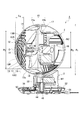
- the rear view of the air blower concerning this embodiment BRIEF DESCRIPTION OF THE DRAWINGS Sectional drawing of the air blower which concerns on this Embodiment.
- the perspective view of the air blower concerning a comparative example The perspective view which shows the ventilation state of the air blower which concerns on this Embodiment.
- (A) Right side view of the grille part with which the air blower which concerns on Example 1 is equipped
- (b) Right side view of the grille part with which the air blower which concerns on Example 2 is equipped
- FIG. 1 The end view of the principal part of the air blower which concerns on a comparative example
- Sectional drawing which shows the internal structure of the air blower which concerns on this Embodiment The perspective view which shows the internal structure of the air blower which concerns on this Embodiment. Sectional drawing which shows the internal structure of the air blower which concerns on this Embodiment. The perspective view which shows the internal structure of the air blower which concerns on this Embodiment. The top view of the control panel with which the air blower concerning this embodiment is provided. Sectional drawing which shows the left-right oscillating mechanism with which the air blower which concerns on this Embodiment is equipped. The disassembled figure of the base part with which the air blower which concerns on this Embodiment is equipped. Sectional drawing which shows the joint of the base part with which the air blower which concerns on this Embodiment is equipped.
- the graph which shows an example of the wind volume adjustment pattern of the rhythm wind of the fan which concerns on this Embodiment. It is a graph which shows the control method of the rhythm style shown by FIG. 24, and when making the voltage applied to a motor into a fixed value (b) when changing the voltage applied to a motor gradually.
- A Sectional drawing of the grille part with which the air blower which concerns on Example 1 is equipped
- B Sectional drawing of the grille part with which the air blower which concerns on a modification is equipped.
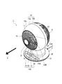
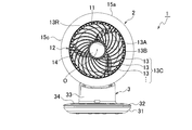
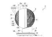
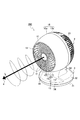
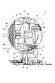
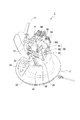
- FIG. 1 to 5 are external views showing a blower 1 according to the present embodiment, FIG. 1 is a perspective view, FIG. 2 is a front view, FIG. 3 is a right side view, FIG. 4 is a top view, and FIG. It is a rear view.
- the blower 1 is configured to enhance the wind speed by a spherical grille structure, and to look compact by an evolutionary design of a spherical shape.
- the blower 1 has a blower opening 11 on the front side and a blower unit 2 provided with a grill 12 on the blower opening 11 as shown in FIGS. 1 to 5. And the pedestal portion (support portion) 3 for supporting the blower portion 2.
- the grill 12 is provided with a plurality of fins 13 in a spiral shape, and an inner end portion 13A close to the central portion O of the spirals of the plurality of fins 13 However, it protrudes in the blowing direction 4 from the outer end 13 B continuous with the blowing port 11. In other words, the inner end 13A protrudes in the blowing direction 4 with respect to the outer end 13B of the portion 13C in which the plurality of fins 13 in the grill 12 are formed.
- the inner end portion 13A is an inner end side closer to the central portion O of the spiral and includes the vicinity of the inner end.
- the outer end portion 13 ⁇ / b> B is a portion on the outer end side continuous with the air outlet 11.
- the protrusion amount L 1 of the inner end portion 13A to the outer end portion 13B of the plurality of fins 13 is greater than the longitudinal in the outer end portion 13B direction of the fin width W It is preferable that it is set.
- the protrusion amount L 1 here corresponds to the distance of the front and rear direction to the front end of the inner end portion 13A from the front end of the outer end portion 13B.
- the fin width dimension W is a width dimension in the front-rear direction of the fins 13.
- the fin 13 having a constant fin width W is exemplified, and the outer end 13 B of the fin 13 is continuous with the air outlet 11.
- the amount of projection of the inner end 13A with respect to the outer end 13B of the plurality of fins 13 is “the inner portion of the portion 13C in which the plurality of fins 13 in the grill 12 are formed. It can also be reworded as "the amount of protrusion" of the end portion 13A.
- the portion 13C in which the plurality of fins 13 are formed is a portion of the grill 12 excluding the cap 14 at the center O of the spiral. This can sufficiently ensure the protrusion amount L 1 of the inner end portion 13A to the outer end portion 13B of the plurality of fins 13, wind can be reliably effective to collect in the center.
- the plurality of fins 13 portions 13C in which the plurality of fins 13 of the grille 12 are formed gradually protrude in the blowing direction 4 as they go from the outer end 13B toward the center O of the spiral. .
- the effect of collecting the wind at the center can be efficiently exhibited, and the wind speed can be reliably improved.
- the plurality of fins 13 are preferably curved so as to be convex in the blowing direction 4. Thereby, the wind speed can be improved more efficiently by making the grille 12 into a curved shape (spherical shape).
- an air outlet 11 of the blower portion 2 is formed in a circular, configured protrusion amount L 1 of the inner end portion 13A to the outer end portion 13B of the plurality of fins 13 is greater than 20% of the diameter of the air blowing port 11 It is done.
- the inner end 13 A of the portion 13 C in which the plurality of fins 13 of the grill 12 is formed protrudes in the blowing direction 4 beyond 20% of the diameter of the blowing port 11.
- the ventilation part 2 has the cover 15 which forms an outer surface, and the cylindrical wind tunnel part 16 provided in the inner side of a cover.
- the wind speed of the wind which blows off from the ventilation opening 11 is stabilized.
- the wind blown out from the circulator is a spiral air flow which goes straight while winding a swirl, and has high directivity and straightness of wind compared with a fan or the like.
- the cover 15 of the blower unit 2 has a front cover 15a having a grille 12 and a rear cover 15b which can be fitted to the front cover 15a, and in a fitted state where the front cover 15a and the rear cover 15b are fitted.
- it has a spherical shape. This makes it look sleek, compact and without corners. In addition, the cuteness and fashionable feeling of appearance are improved.
- the front cover 15a and the rear cover 15b are formed in a hemispherical shape so as to form a spherical shape in a fitted state, and an air path forming member 60 having an air channel portion 16 is provided inside the front cover 15a. It is preferable that a part of the forming member 60 protrudes from the rear of the front cover 15a. As a result, even when the ball shape is formed in the fitting state, the length of the air passage forming member 60 can be secured.
- the air passage forming member 60 has a cylindrical air tunnel portion 16 and an enlarged diameter cylindrical portion connected to the rear end of the air tunnel portion 16 and gradually increasing in diameter toward the rear. preferable.
- the enlarged diameter cylindrical portion will be described in detail later.
- a configuration is illustrated in which a circular ring 13R intersecting each fin 13 is provided to prevent fingers from entering through the gaps between the plurality of fins 13 and 13 and also to reinforce the grille 12.
- the ring 13R may not be present.
- blower 1 according to the present embodiment will be described in more detail with reference to FIGS.
- the cover 15 of the blower unit 2 includes the front cover 15a and the rear cover 15b.
- the front cover 15a is, for example, a hemispherical cover formed of a synthetic resin material such as polypropylene, and a spherical grille 12 is provided on a circular air outlet 11 opened to the front.
- the rear cover 15b is also a hemispherical cover formed of, for example, a synthetic resin material such as polypropylene.
- a large number of vents 21 for taking in the outside air are formed over substantially the entire surface of the rear cover 15b.
- the grill 12 is, for example, a front panel formed of a high impact resistant synthetic resin material.
- the spiral fin 13 is formed in a convex curved shape so as to gradually protrude toward the center O of the spiral.
- the pedestal portion 3 supports the air blowing portion 2 so as to be able to swing from side to side, and is mounted on the installation surface.
- the pedestal portion 3 has a pedestal lower portion 31 formed in a circular shape in a plan view, and a pedestal upper portion 32 which can be fitted to the pedestal lower portion 31.
- the cover that forms the outer surface of both the base lower portion 31 and the base upper portion 32 can be made of, for example, a synthetic resin material such as polypropylene.
- a single-legged support portion 33 is vertically erected rearward of the center of the pedestal upper portion 32, and an operation panel 34 is disposed forward of the support portion 33.
- the pedestal portion 3 is illustrated as the support portion 3, the support portion 3 may have a structure that can be attached to a ceiling or the like.
- FIG. 6 is a cross-sectional view of blower 1 according to the present embodiment.
- the blower unit 2 is a blower that generates an air flow, and includes a fan 17 for blowing and a motor 18 that drives the fan 17.
- An axial flow propeller fan is employed as the air blowing fan 17 in order to generate a large air flow.
- a motor 18 for the fan 17 a general AC condenser motor is adopted as a motor 18 for the fan 17.
- the diameter R 0 of the fan 17 is about 120 mm to about 240 mm.
- the blower 1 uses a motor M1 for left and right swing and a motor M2 for upper and lower swing in order to automatically perform left and right swing and vertical swing.
- a motor M1 for left and right swing and a motor M2 for upper and lower swing is required to be small in size so as to be housed inside the product.
- a synchronous motor is adopted.
- the left and right swing and the upper and lower swing are automatically performed, the present invention is not limited to this. For example, only left and right swing may be performed automatically.
- FIG. 7 is a perspective view of a blower 100 according to a comparative example.
- the blower 100 according to the comparative example is a circulator provided with a flat grille structure. That is, the outer peripheral shape is provided with the ventilation part 2 formed in a substantially drum shape, and the planar grill 12 is provided in the circular ventilation opening 11 opened to the front.
- a flat grille 12 also has a plurality of spiral fins 13 in the same manner.
- the portion of the front cover 15a excluding the grille 12 is formed in a rounded truncated cone shape.
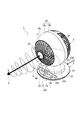
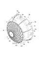
- FIG. 8 is a perspective view showing a blowing state of the blower 1 according to the present embodiment.
- the blower 1 according to the present embodiment is a circulator having a spherical grille structure. Therefore, a rotational force is applied to the wind blown forward from the grill 12 so as to wind a vortex converging to the center of the blowing direction 4. As a result, the wind gathers at the center, and the wind speed at the center of the blowing direction 4 can be improved.
- the blower 1a according to the first embodiment and the blower 1b according to the second embodiment will be described in more detail.
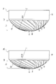
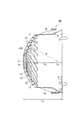
- FIG.9 (a) is a right view of the grill 12 part provided with the air blower 1a based on Example 1
- FIG.9 (b) is a right side view of the grill 12 part provided with the air blower 1b based on Example 2.
- FIG. 9A in the blower 1a according to the first embodiment, for example, when the diameter R 0 of the fan 17 is about 150 mm, the curvature radius R of the grill 12 is about 105 mm.
- the curvature radius R of the grill 12 is about 92 mm.
- the basic structures of the fans 1a and 1b according to the first and second embodiments are the same except that the radius of curvature R of the grill 12 is different.
- the blower 1a according to the first embodiment and the blower 1b according to the second embodiment are the same in that the front end of the inner end 13A protrudes from the front end of the outer end 13B.
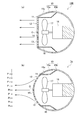
- FIG.10 (a) is an end elevation of the principal part of the air blower 100 which concerns on a comparative example
- FIG.10 (b) is an end elevation of the principal part of the air blower 1a which concerns on Example 1.
- FIG. Arrows in the figure indicate the flow of the wind blown out from the blower 11.
- Fig.10 (a) in the air blower 100 which concerns on a comparative example, since the several spiral fin 13 is arrange
- FIG. On the other hand, as shown in FIG.
- the blower 1b according to the second embodiment is also the same in that the wind is likely to be collected at the center of the blowing direction 4.
- the center of the blowing direction 4" may be rephrased as "the front of the center of the blowing port 11" or "an extension of a straight line parallel to the rotation axis of the fan 17 and passing through the central portion O of the spiral". it can.
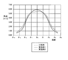
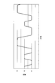
- FIG. 11 is a graph which shows the test result of the wind speed of a comparative example and Example 1, 2.
- the vertical axis indicates the wind speed [m / s]
- the horizontal axis indicates the distance in the left-right direction with the center of the blowing direction 4 as the reference position “0”.
- reference numeral P -4 ⁇ P 4 shown in the horizontal axis respectively correspond to the position of the code P -4 ⁇ P 4 shown in Figure 10 (b).
- the wind speed decreases as the distance in the left-right direction increases.
- the waveform of the comparative example is substantially flat near the center of the blowing direction 4
- the waveforms of the first and second embodiments have a mountain shape near the center of the blowing direction 4. That is, in the vicinity of the center of the blowing direction 4, the wind speed is higher in Examples 1 and 2 than in the comparative example.
- Example 1 curve radius R105
- Example 2 curve radius R92
- the radius of curvature R of the grille 12 is preferably about 80 mm to about 120 mm (more preferably about 90 mm to about 110 mm), for example, when the diameter R 0 of the fan 17 is about 150 mm.
- the diameter R 0 fans 17 is about 150 mm, the diameter R 0 fans 17, for example, can be appropriately changed in a range of from about 120 mm ⁇ about 240 mm. It goes without saying that if the diameter R 0 of the fan 17 changes, the preferred range (about 80 mm to about 120 mm) of the curvature radius R of the grille 12 also changes accordingly.
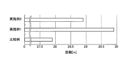
- FIG. 12 is a graph which shows the test result of the reach
- the reaching distance [m] of the wind was about 30 m in Example 1 and about 29 m in Example 2, while the comparative example was about 28 m.
- the radius of curvature of the grille 12 is R
- the diameter of the fan 17 is R 0
- the outer diameter of the blower 2 is R 1
- the diameter of the blower 11 is R 2 .
- the cylindrical wind tunnel 16 may be slightly expanded or contracted in diameter.
- the preferable range of the curvature radius R of the grill 12 is about 80 mm to about 120 mm (more preferably about 90 mm to about 110 mm), and the actual value is about 105 mm. is there.
- the grill 12 in the blower unit 2 has a distorted shape.
- the lower limit here is about 53.3% (more preferably, about 60.0%) of the diameter R 0 of the fan 17.
- the curvature radius R of the grille 12 exceeds the upper limit value, the effect of increasing the wind speed can not be obtained sufficiently.
- the upper limit here is about 80.0% (more preferably about 73.3%) of the diameter R 0 of the fan 17.
- the preferable range of the outer diameter R 1 of the blower section 2 is about 160 mm to about 240 mm.
- the outer diameter R 1 of the blower 2 is less than about 107% of the diameter R 0 fans 17, can not be secured clearance of the fan 17 and the air duct 16, is a risk that the inner surface of the fan 17 and the air duct 16 is in contact Yes, it is also difficult to make.
- the outer diameter R 1 of the blower 2 is greater than about 160% of the diameter R 0 fans 17, the size of the blower 2 becomes excessive, the balance of the pedestal portion 3 collapses top-heavy.
- the preferable range of the diameter R 2 of the air outlet 11 is about 155 mm to about 175 mm.
- the diameter R 2 of the air blowing port 11 is less than about of 103% of the diameter R 0 fans 17, can not be secured clearance of the fan 17 and the air duct 16, there is a possibility of contact, fabrication is difficult.
- the diameter R 2 of the air blowing port 11 is greater than about to 117% of the diameter R 0 fans 17, can not be secured length of the air channel portion 16 in the bellows section 2 of the spherical, wind blown directed It is difficult to maintain sex and straightness.
- R 2 / R 1 the area of the air outlet 11 in the front view of the air blower 2 can be seen to be small.
- the diameter R 2 of the air blowing port 11 is less than about 74% of the outer diameter R 1 of the blower unit 2, it can not be secured clearance of the fan 17 and the air duct 16, a possibility of contact is increased more.
- the diameter R 2 of the air blowing port 11 is greater than about 83% of the outer diameter R 1 of the blower unit 2, it can not be secured length of the air channel portion 16 in the bellows section 2 of the spherical, wind blown It becomes more difficult to maintain the directivity and straightness of
- the blower unit 2 has a sophisticated spherical shape and thus looks compact without corners. In addition, the cuteness and fashionable feeling of appearance are improved. On the other hand, in order to stabilize the wind speed of the wind blown from the blower 1, the wind tunnel part 16 of a fixed length is required. Therefore, the blower 1 according to the present embodiment adopts the following configuration.
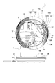
- FIG. 13 is a perspective view of air passage forming member 60 provided in blower 1 according to the present embodiment.
- the air passage forming member 60 is a member for forming an air passage, and has a grill 12, an air channel portion 16 and an enlarged diameter cylindrical portion 19.
- the air passage forming member 60 is formed by integrally molding the grille 12, the air channel portion 16, and the enlarged diameter cylindrical portion 19 with a synthetic resin material.
- the air channel portion 16 is a cylindrical member provided radially outward of the fan 17, and the inner diameter of the air channel portion 16 is substantially equal to the inner diameter of the air outlet 11.
- the enlarged diameter cylindrical portion 19 is a portion fitted with the rear cover 15b, and is a tapered cylindrical member whose diameter gradually increases toward the rear.
- the rear end 19 a of the enlarged diameter cylindrical portion 19 is provided with a plurality of locking claws 19 b that engage with the rear cover 15 b.
- a plurality of reinforcing ribs 19c are erected at right angles on the outer peripheral surface from the wind tunnel portion 16 to the enlarged diameter cylindrical portion 19, and the strength of the enlarged diameter cylindrical portion 19 is secured.
- the outer edge of the reinforcing rib 19c is formed to abut on the inner surface of the outer spherical cover member 15C.
- the front surface of the grille 12 (the front end faces of the plurality of fins 13) and the outer peripheral surface of the exterior spherical cover member 15C form a continuous spherical surface.
- the front surface of the grille 12 (the front end surface of the plurality of fins 13) and the outer peripheral surface of the outer spherical cover member 15C constitute a continuous spherical surface. There is no difference in level, and it can be made a beautiful spherical shape, and the aesthetics can be improved.
- the directivity and straightness of the wind blown out are improved, and the performance as a circulator is stabilized.
- FIG. 14 is a cross-sectional view of air passage forming member 60 provided in blower 1 according to the present embodiment.
- the length of the air passage forming member 60 is L 0
- the amount of projection of the grill 12 is L 1
- the length of the air channel 16 is L 2
- the length of the enlarged diameter cylinder 19 is L 3
- the radius of curvature of the grille 12 is R
- the taper angle of the inner peripheral surface of the enlarged diameter cylindrical portion 19 is ⁇ .
- the diameter R 0 of the fan 17 is about 150 mm. It goes without saying that if the diameter R 0 of the fan 17 changes, the size of each part also changes accordingly.
- the preferred range of the length L 2 of the air channel 16 is about 45 mm to about 60 mm, and the actual value is about 50 mm.
- the preferred range of the length L 2 of the wind tunnel 16 can also be said to be about 30% to about 40% of the diameter R 0 (about 150 mm) of the fan 17. If the wind tunnel 16 is made longer, directivity and straightness of the wind can be secured.
- the length L 2 of the air channel portion 16 is less than about 30% of the diameter R 0 fans 17 (about 45 mm), the air channel portion 16 is excessively small, it can not be ensured directionality and linearity of the wind.
- the length L 0 of the air passage forming member 60 main body is set larger than the curvature radius R (about 105 mm) of the grille 12. Therefore, the rear end (expanded diameter cylindrical portion 19) of the air passage forming member 60 protrudes rearward from the hemispherical front cover 15a, and the rear end of the air passage forming member 60 is inserted into the rear cover 15b.
- the air path forming member 60 length L 0 of the main body is long, but he easily secured length L 2 of the air duct 16, because it forms a grill 12 in a spherical shape, extending the air channel portion 16 at the front it is impossible to increase the length L 2.
- the length L 0 of the air path forming member 60 body is set larger than the radius of curvature R of the grill 12, is charged with part of the rear of the enlarged diameter cylindrical portion 19 of the air channel portion 16 to the rear cover 15b Thus, the length L 2 of the wind tunnel 16 is secured.
- the length L 3 of the flare tube portion 19 can be sufficiently secured.
- the taper angle ⁇ of the enlarged diameter cylindrical portion 19 is set to 15 degrees to 30 degrees.
- the taper angle ⁇ of the enlarged diameter cylindrical portion 19 is set to 15 degrees to 30 degrees.
- the taper angle ⁇ of the enlarged diameter cylindrical portion 19 is less than 15 degrees, it is difficult to obtain the effect of increasing the flow velocity due to the reduction of the flow passage area at the portion entering the wind tunnel 16 from the enlarged diameter cylindrical portion 19.
- the taper angle ⁇ exceeds 30 degrees, the ventilation resistance in the enlarged diameter cylindrical portion 19 becomes large, and there is a possibility that the flow of air from behind can not be smooth.
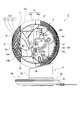
- FIG. 15 (Relationship between fan and air path forming member)
- the flow path of the air 61 flowing in the blower 1 is shown.
- the air 61 flowing in the fan 1 enters the wind tunnel 16 from the large-diameter cylindrical portion 19, the flow velocity increases due to the reduction of the flow passage area. This contributes to the increase of the wind speed of the wind blown out from the blower 11.
- the air passage forming member 60 surrounds the outside of the fan 17, and the air passage forming member 60 extends rearward from the rear end position of the fan 17.
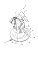
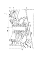
- FIG. 17 is a perspective view in the case where the cover 15 and the air passage forming member 60 are removed and seen down from diagonally left rear.
- FIG. 16 is a cross-sectional view in the case of being cut leftward from the center of the blower portion 2
- FIG. 17 is a perspective view in the case where the cover 15 and the air passage forming member 60 are removed and seen down from diagonally left rear.
- the motor cover 71 is sandwiched from both sides by the columns 70 raised from the pedestal portion 3 and the air blower portion 2 is mounted on the pedestal portion 3 with the sandwiching position as the shaft 72 of the upper and lower swing. Swing against the top and bottom. Therefore, the electric cable 73 connected to the motor 18 (see FIG. 6) for the fan 17 and the motor M2 (see FIG. 6) accommodated in the motor cover 71 is pulled out from the shaft 72 of the upper and lower swing. May be The electric cable 73 drawn from the upper and lower swinging shaft 72 is taken into the inside of the pedestal 3 from the opening 36 formed in the upper surface 35 of the pedestal 3. An electrical cable 73 may be secured to the support 70 at an appropriate position.
- FIG. 18 is a cross-sectional view in the case of cutting the right side from the center of the blower section 2
- FIG. 19 is a perspective view in the case where the cover 15 and the air passage forming member 60 are removed FIG.
- the output shaft 94 of the motor M2 for vertical oscillation is connected to the support 70 via the link mechanism 90 for vertical oscillation.
- the link mechanism 90 includes a swing arm member 91 fixed to the output shaft 94 of the motor M2 for vertical swing, a fixed member 93 fixed to the support 70, and a swing arm member at one end.
- An arc-shaped link member 92 pivotally connected to the other end 91 is pivotally attached to the fixed member 93.
- the rubber washer 95 may be fitted between the swing arm member 91 and the link member 92, and the rubber washer 96 may be fitted between the link member 92 and the fixing member 93.
- the vibration is absorbed by the rubber washers 95 and 96, so that abnormal noise of the link mechanism 90 due to the backlash of the synchronous motor (motor M2 for vertical oscillation) and the clearance between the members 91, 92, 93 can be prevented.
- one of the two rubber washers 95 and 96 may be omitted.
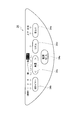
- FIG. 20 is a plan view of operation panel 34 provided in blower 1 according to the present embodiment.
- the operation panel 34 includes, as shown in FIG. 20, a power button 34a, an off timer button 34b, an air volume button 34c, a rhythm button 34d, a swing button 34e, and the like.
- the power button 34a is a button for setting power on / off.
- the off timer button 34 b is a button for setting the off timer.
- the air volume button 34 c is a button for adjusting the air volume of the blower unit 2 and switches the setting of the air volume into five levels in the order of weak air, weak, medium, strong and turbo each time the air volume button 34 c is pressed.
- the rhythm button 34 d is a button for setting a rhythm style to be described later.
- the swing button 34 e is a button for setting on / off of the upper and lower swing and the left and right swing.
- the rear cover 15b will be described in more detail with reference to FIG.
- a large number of vent holes 21 for taking in the outside air are formed over substantially the entire surface of the rear cover 15b.
- the air hole 21a is added to the rear portion of the motor of the rear cover 15b. Therefore, when the motor 18 is driving the fan 17, the outside air is taken in also from the air holes 21a at the rear of the motor, so a larger amount of air can be secured and the cooling effect by the air flow generated by the motor 18 itself It is also a measure against heat.
- FIG. 21 is a cross-sectional view showing the left and right swing mechanism 43 provided in the blower 1 according to the present embodiment.
- the left and right swing mechanism 43 includes a resin fixed plate 41 fixed to the pedestal upper portion 32, a central shaft 42 integrated with the fixed plate 41 by insert molding, and a swing fixed to the upper surface of the fixed plate 41. And a motor M1.
- a resin bearing member (bush) 44 into which the lower end of the central shaft 42 is inserted is provided, and a locking claw 44 a is integrally molded on the lower inner peripheral portion of the bearing member 44.
- a notch groove 42a is formed on the lower end outer peripheral portion of the central shaft 42, and a locking claw 44a is press-fit into the notch groove 42a.
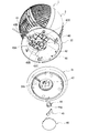
- FIG. 22 is an exploded view of the pedestal 3 provided in the blower 1 according to the present embodiment.
- the left and right swing mechanism 43 will be described in more detail below with reference to FIG.
- the pedestal 3 is hollow inside, and the left and right swing mechanism 43 is housed inside the hollow.
- the left and right swing mechanism 43 includes a fixed plate 41, a swing motor M1 (see FIG. 21) fixed to the upper surface of the fixed plate 41, and an eccentric cam 43A fixed to the output shaft 43E of the swing motor M1.
- a fixed shaft 43D fixed to the pedestal lower portion 31 and an arc-shaped connecting link 43B pivotally attached to the eccentric cam 43A at one end and pivoted to the fixed shaft 43D at the other end.
- the fixing plate 41 is fixed to the pedestal upper portion 32, and the central shaft 42 is pivotably inserted into the bearing member 44.
- the oscillating motor M1 including the eccentric cam 43A fixed to the output shaft 43E) and the fixed shaft 43D are provided at positions away from the central shaft 42, respectively.
- a cylindrical bearing member 44 having a locking claw 44a formed on the lower end inner peripheral portion is inserted into the shaft insertion hole 47 opened in the pedestal lower portion 31.
- the central shaft 42 is inserted into the bearing member 44.
- a notched groove 42a is formed on the outer periphery of the lower end of the central shaft 42, and an engaging claw 44a to be an engaging piece is press-fit into the notched groove 42a.
- the cord holder 45 is attached to the lower portion of the bearing member 44, and the opening 31b on the lower surface of the pedestal lower portion 31 is covered with the bottom cap 46.
- the fixed plate 41 and the upper end portion of the central shaft 42 are insert-molded, and the pedestal upper portion 32 and the pedestal lower portion 31 are connected by the central shaft 42, and the bearing member 44 of the central shaft 42 is fixed to the pedestal lower portion 31.
- the central shaft 42 is inserted into the shaft insertion hole 47 via the bearing member 44, the clearance between the central shaft 42 and the shaft insertion hole 47 is eliminated, and the wear of the shaft insertion hole 47 due to the turning of the central shaft 42 The generation of abnormal noise can be prevented, and the pivoting of the pedestal upper portion 32 (the blower 2) around the central axis 42 can be smooth.
- the eccentric cam 43A fixed to the output shaft 43E of the motor M1 for swinging is eccentrically rotated and pivotally attached to the eccentric cam 43A.
- One end of the connection link 43B is circularly moved. Since the other end of the connecting link 43B is pivotally attached to the fixed shaft 43D fixed to the pedestal lower portion 31, the pedestal upper portion 32 and the blower portion 2 mounted thereon by this circular motion centering on the central shaft 42 According to the radial distance of the circular movement, it will turn (swing) in the left and right direction.
- the pedestal lower portion 31 and the pedestal upper portion 32 swingably provided on the pedestal lower portion 31 are connected through the central axis 42 and the air is blown onto the pedestal upper portion 32
- the fan 1 is provided with the portion 2 and the bearing member 44 is inserted into the pedestal lower portion 31, the central shaft 42 is rotatably inserted into the bearing member 44, and the fixing plate 41 provided on the pedestal upper portion 32
- the upper end portion of the central shaft 42 is insert-molded.
- the fixing plate 41 provided on the pedestal upper portion 32 is formed of resin. Therefore, when the wiring is in contact with the edge (corner) of the fixing plate 41, the wiring can be prevented from being damaged.
- a locking claw 44a is integrally molded of resin on the inner peripheral portion of the lower end of the bearing member 44 of the central shaft 42.
- the locking claw 44a functions as an alternative to the E-ring, so that it is not necessary to use the E-ring, and the number of parts can be reduced and the cost can be reduced.
- FIG. 23 is a cross-sectional view showing a joint of pedestals 3 provided in blower 1 according to the present embodiment.
- an annular inner wall 31 a is erected inside the periphery of the pedestal lower portion 31, and the periphery of the pedestal upper portion 32 is placed on the annular inner wall 31 a of the pedestal lower portion 31.
- the gap between the pedestal upper portion 32 and the pedestal lower portion 31 is hidden by the annular inner wall 31a and becomes inconspicuous.
- dust and the like are less likely to intrude into the inside of the pedestal portion 3 through the gap between the pedestal upper portion 32 and the pedestal lower portion 31.
- the blower 1 includes a control unit 50 that controls power on / off, an operation of an off timer, the number of rotations of the motor 18, an operation of a swing, and the like.
- the control unit 50 is a control board including a central processing unit (CPU), a read only memory (ROM), a random access memory (RAM), and the like (see FIG. 6).
- CPU central processing unit
- ROM read only memory
- RAM random access memory
- the control unit 50 controls the number of rotations of the motor 18 to realize rhythmic wind.
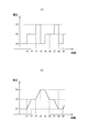
- FIG. 24 is a graph showing an example of an air volume adjustment pattern of rhythmic wind blown out from the blower 1 according to the present embodiment.
- the horizontal axis shows time, and the vertical axis shows the setting of air volume.
- a weak wind and a strong wind are switched so as not to be a simple repetition so that the effect of fluctuation is generated to approximate natural wind.
- air volume control (1) means that the operation period of the air volume F2 is set to 15 seconds.
- the air volume F1 may correspond to the air volume "slight wind”
- the air volume F2 may correspond to the air volume "weak”
- the air volume F3 may correspond to the air volume "medium”.
- Air flow F2 for 15 seconds ⁇ (2) Air flow F1 for 15 seconds ⁇ (3) Air flow F2 for 15 seconds ⁇ (4) Air flow F1 for 15 seconds ⁇ (5) Air flow F3 30 seconds ⁇ (6) Air flow F1 30 seconds ⁇ (7) air volume F2 15 seconds ⁇ (8) air volume F1 15 seconds ⁇ (9) air volume F3 30 seconds ⁇ (10) air volume F1 30 seconds ⁇ (11) air volume F2 15 seconds ⁇ ( 12) Airflow F1 from 15 seconds ⁇ (13) Airflow F2 from 15 seconds ⁇ (14) Airflow F1 from 15 seconds ⁇ (15) Airflow F3 from 30 seconds ⁇ (16) Airflow F1 from 30 seconds ⁇ (17) Airflow F2 15 seconds ⁇ (18) air volume F1 for 15 seconds ⁇ (19) air volume F2 for 15 seconds ⁇ (20) air volume F1 for 15 seconds ⁇ ...
- the twenty air volume controls (1) to (20) are set as one repeating unit, but the number of air volume controls constituting such one unit is not limited. Also, although three air volumes F1, F2, and F3 are illustrated as air volumes used for rhythmic wind, the number of wind volumes used for rhythmic wind and the strength of the air volume are not limited either. Also, although one unit of air flow control is illustrated as 15 seconds or 30 seconds, it is free to increase or decrease the number of unit seconds.
- FIG. 25 is a graph showing the rhythm-like control method shown in FIG.
- the horizontal axis shows time
- the vertical axis shows voltage applied to the motor 18.
- the voltage applied to the motor 18 may be gradually changed to gradually change the rotational speed of the motor 18 when the air volume is switched.
- the torque applied to the fan 17 is gradually increased, and the load on the motor 18 due to the air resistance of the fan 17 is reduced.
- the air volume can be switched smoothly by gradually changing the number of rotations of the motor 18, that is, the number of rotations of the fan 17, more natural wind can be obtained, and when the air volumes are switched. The sound of fan 17 can be reduced.
- the control unit 50 repeats the rhythmic air volume adjustment pattern including a plurality of air volume controls in which the plurality of air volume strengths and the unit seconds are combined (irregularly). You can switch between a weak wind and a strong wind so as not to be a simple repetition, produce a fluctuating effect, and bring it closer to a natural wind.
- control unit 50 when controlling the rhythm wind, gradually increases / decreases the voltage value of the motor 18 that drives the fan 17. As a result, since the air volume can be switched gently, the air can be brought closer to a more natural wind, and furthermore, the sound of the fan 17 when the air volume is switched can be reduced.
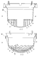
- FIG.26 (a) is sectional drawing of the air path formation member 60 with which the air blower 1a which concerns on Example 1 is equipped
- FIG.26 (b) is sectional drawing of the air path formation member 60c with which the air blower which concerns on a modification is equipped. is there.
- the fin width dimension W in the front-rear direction of the fins 13 is substantially constant in any part.
- the fin width dimension W of the fins 13 in the front-rear direction is different, and the fin width dimension W gradually becomes closer to the inner end 13A from the outer end 13B of the fin 13.
- the positions of the rear ends of all the fins 13 are aligned with the position of the air outlet 11. That is, when the grill 12 is seen from the back side, the height position of all the fins 13 is flat. Even in such a modification, as in the first and second embodiments, it can be expected that the wind tends to be concentrated at the center of the blowing direction 4 as compared with the comparative example.
- the fins 13 are provided in a spiral shape, and the inner end 13A near the center O of the swirl of the fins 13 is in the blowing direction 4 from the outer end 13B continuous with the air outlet 11 It should be protruding.
- this embodiment is included.
- the shape of the grill 12 as viewed from the side is not only a curved shape but also a shape with two mountains, a trapezoidal shape, a shape in which only the central portion is recessed, a step shape, a shape similar to a mosque of an Islamic temple, Mt.
- Various shapes, such as a shape can be adopted.
- the present embodiment includes various embodiments and the like not described herein.
Landscapes
- Engineering & Computer Science (AREA)
- Mechanical Engineering (AREA)
- General Engineering & Computer Science (AREA)
- Chemical & Material Sciences (AREA)
- Combustion & Propulsion (AREA)
- Geometry (AREA)
- Physics & Mathematics (AREA)
- Structures Of Non-Positive Displacement Pumps (AREA)
- Ventilation (AREA)
- Air-Flow Control Members (AREA)
- Duct Arrangements (AREA)
- Low-Molecular Organic Synthesis Reactions Using Catalysts (AREA)
- Control Of Positive-Displacement Air Blowers (AREA)
Priority Applications (15)
| Application Number | Priority Date | Filing Date | Title |
|---|---|---|---|
| KR1020207007294A KR102195764B1 (ko) | 2017-09-29 | 2018-09-26 | 서큘레이터 |
| CN201880059153.XA CN111094755B (zh) | 2017-09-29 | 2018-09-26 | 循环器 |
| EP18859996.3A EP3690250B1 (en) | 2017-09-29 | 2018-09-26 | Blower |
| EP22165933.7A EP4039982B1 (en) | 2017-09-29 | 2018-09-26 | Blower |
| CA3075731A CA3075731C (en) | 2017-09-29 | 2018-09-26 | Blower |
| US16/646,983 US10859287B2 (en) | 2017-09-29 | 2018-09-26 | Air circulator |
| KR1020207036362A KR102285658B1 (ko) | 2017-09-29 | 2018-09-26 | 서큘레이터 |
| KR1020227008171A KR102495036B1 (ko) | 2017-09-29 | 2018-09-26 | 서큘레이터 |
| CN202110526699.5A CN113250984B (zh) | 2017-09-29 | 2018-09-26 | 循环器 |
| ES18859996T ES2918125T3 (es) | 2017-09-29 | 2018-09-26 | Soplador |
| KR1020217023404A KR102378135B1 (ko) | 2017-09-29 | 2018-09-26 | 서큘레이터 |
| MX2020003184A MX2020003184A (es) | 2017-09-29 | 2018-09-26 | Soplador. |
| US17/081,882 US11402120B2 (en) | 2017-09-29 | 2020-10-27 | Air circulator |
| US17/648,877 US11686500B2 (en) | 2017-09-29 | 2022-01-25 | Air circulator |
| US18/315,100 US20230272941A1 (en) | 2017-09-29 | 2023-05-10 | Air circulator |
Applications Claiming Priority (4)
| Application Number | Priority Date | Filing Date | Title |
|---|---|---|---|
| JP2017191401 | 2017-09-29 | ||
| JP2017-191401 | 2017-09-29 | ||
| JP2018026445A JP6363811B1 (ja) | 2017-09-29 | 2018-02-16 | サーキュレータ |
| JP2018-026445 | 2018-02-16 |
Related Child Applications (2)
| Application Number | Title | Priority Date | Filing Date |
|---|---|---|---|
| US16/646,983 A-371-Of-International US10859287B2 (en) | 2017-09-29 | 2018-09-26 | Air circulator |
| US17/081,882 Division US11402120B2 (en) | 2017-09-29 | 2020-10-27 | Air circulator |
Publications (1)
| Publication Number | Publication Date |
|---|---|
| WO2019065685A1 true WO2019065685A1 (ja) | 2019-04-04 |
Family
ID=62976638
Family Applications (1)
| Application Number | Title | Priority Date | Filing Date |
|---|---|---|---|
| PCT/JP2018/035578 WO2019065685A1 (ja) | 2017-09-29 | 2018-09-26 | 送風機 |
Country Status (10)
| Country | Link |
|---|---|
| US (4) | US10859287B2 (zh) |
| EP (2) | EP3690250B1 (zh) |
| JP (8) | JP6363811B1 (zh) |
| KR (4) | KR102495036B1 (zh) |
| CN (2) | CN111094755B (zh) |
| CA (1) | CA3075731C (zh) |
| ES (1) | ES2918125T3 (zh) |
| MX (1) | MX2020003184A (zh) |
| TW (2) | TWI787519B (zh) |
| WO (1) | WO2019065685A1 (zh) |
Cited By (1)
| Publication number | Priority date | Publication date | Assignee | Title |
|---|---|---|---|---|
| CN112503030A (zh) * | 2020-12-03 | 2021-03-16 | 泛仕达机电股份有限公司 | 一种降噪导流栅 |
Families Citing this family (16)
| Publication number | Priority date | Publication date | Assignee | Title |
|---|---|---|---|---|
| KR102093412B1 (ko) | 2018-03-07 | 2020-03-25 | 엘지전자 주식회사 | 공기조화기 |
| JP6960679B2 (ja) * | 2018-04-23 | 2021-11-05 | アイリスオーヤマ株式会社 | 加湿器 |
| TWD202149S (zh) * | 2018-10-03 | 2020-01-11 | 日商愛麗思歐雅瑪股份有限公司 | 循環器 |
| JP1640923S (zh) * | 2018-10-03 | 2019-09-09 | ||
| TWD202151S (zh) * | 2018-10-04 | 2020-01-11 | 日商愛麗思歐雅瑪股份有限公司 | 循環器 |
| JP6692100B2 (ja) * | 2018-10-10 | 2020-05-13 | アイリスオーヤマ株式会社 | 送風機 |
| CN111622992A (zh) * | 2019-02-28 | 2020-09-04 | 施耐德电气It公司 | 风扇罩 |
| JP1654102S (zh) * | 2019-04-19 | 2020-03-02 | ||
| JP1654101S (zh) * | 2019-04-19 | 2020-03-02 | ||
| JP7328850B2 (ja) * | 2019-09-26 | 2023-08-17 | シャープ株式会社 | 送風装置及び送風方法 |
| KR102317240B1 (ko) * | 2020-04-20 | 2021-10-26 | 주식회사 유니크테크노 | 서큘레이터 및 그 모션 제어 구현방법 |
| JP6858433B2 (ja) * | 2020-11-16 | 2021-04-14 | アイリスオーヤマ株式会社 | 送風機 |
| CN112628179A (zh) * | 2020-12-31 | 2021-04-09 | 珠海格力电器股份有限公司 | 送风装置 |
| US20220282736A1 (en) * | 2021-03-08 | 2022-09-08 | Macroair Technologies, Inc. | System and kit for attachment to a support structure of a control panel for a high-volume low speed fan |
| CN113775569B (zh) * | 2021-09-26 | 2024-04-12 | 浙江银轮机械股份有限公司 | 风机机壳及风机 |
| CN114087214A (zh) * | 2021-11-03 | 2022-02-25 | 广州高标消防设备有限公司 | 一种轴流式消防排烟风机 |
Citations (5)
| Publication number | Priority date | Publication date | Assignee | Title |
|---|---|---|---|---|
| US4927324A (en) * | 1989-01-09 | 1990-05-22 | Vornado Air Circulation Systems, Inc. | Ducted fan |
| JP2001165088A (ja) * | 1999-12-13 | 2001-06-19 | Sanki Printing Kk | 扇風機 |
| US7530783B1 (en) * | 2005-10-28 | 2009-05-12 | Vornado Air Circulation Systems, Inc. | Grill mounting and retaining assembly |
| JP2010054084A (ja) | 2008-08-26 | 2010-03-11 | Twinbird Corp | サーキュレータ |
| US20110223016A1 (en) * | 2008-09-08 | 2011-09-15 | Vornado Air, Llc | Air circulator |
Family Cites Families (44)
| Publication number | Priority date | Publication date | Assignee | Title |
|---|---|---|---|---|
| US2100994A (en) * | 1936-02-06 | 1937-11-30 | Casco Products Corp | Fan guard |
| FR2523696B1 (fr) * | 1982-03-18 | 1988-03-04 | Jeumont Schneider | Procede pour le refroidissement d'un moteur entrainant une turbine determinant l'evacuation de fumees chaudes a l'extremite d'un conduit et dispositif pour la mise en oeuvre de ce procede |
| JPS62133993U (zh) | 1986-02-17 | 1987-08-24 | ||
| US4856968A (en) * | 1988-02-02 | 1989-08-15 | Armbruster Joseph M | Air circulation device |
| USD312124S (en) * | 1988-11-23 | 1990-11-13 | Vornado Air Circulation Systems, Inc. | Fan |
| US5296769A (en) * | 1992-01-24 | 1994-03-22 | Electrolux Corporation | Air guide assembly for an electric motor and methods of making |
| USD358639S (en) * | 1993-09-30 | 1995-05-23 | Duracraft Corporation | Stand with electrical control unit for a portable fan |
| MX9706055A (es) * | 1996-08-09 | 1998-02-28 | Hunter Fan Co | Sistema de sujecion de anillo de aspas. |
| USD413664S (en) * | 1997-08-08 | 1999-09-07 | Vornado Air Circulation Systems, Inc. | Fan |
| JP3174033B2 (ja) * | 1998-12-28 | 2001-06-11 | 株式会社エフアイテイ | 回転円板式の物品供給装置 |
| TW438953B (en) * | 1999-09-20 | 2001-06-07 | Mitsubishi Electric Corp | Blower, blower system and the blowing method of blower system |
| US6364618B1 (en) * | 2000-02-03 | 2002-04-02 | Lakewood Engineering & Mfg. Co. | Fan body assembly |
| CN2782996Y (zh) * | 2005-03-11 | 2006-05-24 | 谢森源 | 可调式进出气气泵 |
| USD608437S1 (en) * | 2007-07-20 | 2010-01-19 | Vornado Air Circulation Systems, Inc. | Fan |
| USD599463S1 (en) * | 2008-10-09 | 2009-09-01 | Israel Gary P | Air circulator |
| USD605280S1 (en) * | 2009-02-10 | 2009-12-01 | Tiger Focus Trading Ltd. | Circulator |
| USD621025S1 (en) * | 2009-07-27 | 2010-08-03 | Camair LLC | Set of fan parts |
| USD621026S1 (en) * | 2009-07-27 | 2010-08-03 | Camair LLC | Set of fan parts |
| JP2011122550A (ja) * | 2009-12-14 | 2011-06-23 | Toshiba Home Technology Corp | 扇風機 |
| CN101761499A (zh) * | 2010-03-02 | 2010-06-30 | 美的集团有限公司 | 一种无刷直流风扇及其控制方法 |
| CN102192164A (zh) * | 2010-03-08 | 2011-09-21 | 艾美特电器(深圳)有限公司 | 一种音乐电风扇及其控制方法 |
| CN102312843A (zh) * | 2010-07-07 | 2012-01-11 | 南京工程学院 | 旋律驱动型电风扇 |
| CN201916224U (zh) * | 2011-01-07 | 2011-08-03 | 邝竞安 | 一种电风扇 |
| JP5786440B2 (ja) * | 2011-05-11 | 2015-09-30 | 東芝ホームテクノ株式会社 | 扇風機 |
| US10907843B2 (en) * | 2011-11-18 | 2021-02-02 | Broan-Nutone Llc | Ventilating system and method |
| JP3174033U (ja) * | 2011-12-21 | 2012-03-01 | 明宙工業股▲ふん▼有限公司 | 扇風機のフロントカバー |
| FR2984971B1 (fr) * | 2011-12-21 | 2019-08-23 | Seb Sa | Roue de ventilation centrifuge, ventilateur correspondant et appareil de cuisson incluant un tel ventilateur |
| CN102536864B (zh) * | 2012-03-20 | 2015-11-18 | 开勒环境科技(上海)股份有限公司 | 一种大型吊式工业风扇 |
| CN202612148U (zh) * | 2012-05-29 | 2012-12-19 | 合一电器(深圳)有限公司 | 一种涡流风扇 |
| JP5787841B2 (ja) * | 2012-08-07 | 2015-09-30 | 三菱電機株式会社 | 送風機及び制御方法 |
| USD688368S1 (en) * | 2012-11-30 | 2013-08-20 | Vornado Air, Llc | Air circulator |
| JP6077897B2 (ja) * | 2013-03-19 | 2017-02-08 | シャープ株式会社 | 送風装置 |
| DE102014111767A1 (de) * | 2014-08-18 | 2016-02-18 | Ebm-Papst Mulfingen Gmbh & Co. Kg | Axialventilator |
| CN104265665A (zh) | 2014-09-26 | 2015-01-07 | 广东又一电器科技有限公司 | 一种球形风扇 |
| USD760370S1 (en) * | 2014-10-27 | 2016-06-28 | O2Cool, Llc | Fan enclosure with spiral grilles |
| JP5702020B1 (ja) * | 2014-11-04 | 2015-04-15 | 株式会社Cmc | 扇風機およびその制御方法 |
| JP2016194275A (ja) * | 2015-04-01 | 2016-11-17 | パナソニックIpマネジメント株式会社 | 送風装置 |
| CN204878014U (zh) * | 2015-08-07 | 2015-12-16 | 林远波 | 一种风扇调速电路 |
| CN205064330U (zh) * | 2015-08-18 | 2016-03-02 | 艾美特电器(九江)有限公司 | 一种风扇摆头机构及风扇 |
| CN206190559U (zh) * | 2016-08-28 | 2017-05-24 | 王慧欣 | 一种电风扇 |
| CN106351860A (zh) * | 2016-10-28 | 2017-01-25 | 桂林大创科技有限公司 | 一种家用风扇及其控制器 |
| CN106837832B (zh) | 2017-01-22 | 2019-03-22 | 佛山市顺德区新双岭机电科技有限公司 | 一种新型的便携式电风扇 |
| CN206429441U (zh) * | 2017-02-07 | 2017-08-22 | 广东世联电器有限公司 | 一种可大角度调节的电风扇 |
| US11541342B2 (en) * | 2018-03-07 | 2023-01-03 | Lg Electronics Inc. | Indoor unit for air conditioner |
-
2018
- 2018-02-16 JP JP2018026445A patent/JP6363811B1/ja active Active
- 2018-05-18 JP JP2018096055A patent/JP6666952B2/ja active Active
- 2018-05-18 JP JP2018096054A patent/JP2019065839A/ja active Pending
- 2018-05-18 JP JP2018096053A patent/JP6660419B2/ja active Active
- 2018-06-28 JP JP2018123074A patent/JP7148955B2/ja active Active
- 2018-09-26 EP EP18859996.3A patent/EP3690250B1/en active Active
- 2018-09-26 WO PCT/JP2018/035578 patent/WO2019065685A1/ja unknown
- 2018-09-26 US US16/646,983 patent/US10859287B2/en active Active
- 2018-09-26 KR KR1020227008171A patent/KR102495036B1/ko active IP Right Grant
- 2018-09-26 KR KR1020217023404A patent/KR102378135B1/ko active IP Right Grant
- 2018-09-26 CN CN201880059153.XA patent/CN111094755B/zh active Active
- 2018-09-26 EP EP22165933.7A patent/EP4039982B1/en active Active
- 2018-09-26 MX MX2020003184A patent/MX2020003184A/es unknown
- 2018-09-26 CN CN202110526699.5A patent/CN113250984B/zh active Active
- 2018-09-26 ES ES18859996T patent/ES2918125T3/es active Active
- 2018-09-26 CA CA3075731A patent/CA3075731C/en active Active
- 2018-09-26 KR KR1020207007294A patent/KR102195764B1/ko active IP Right Grant
- 2018-09-26 KR KR1020207036362A patent/KR102285658B1/ko active IP Right Grant
- 2018-09-27 TW TW108119530A patent/TWI787519B/zh active
- 2018-09-27 TW TW107134119A patent/TWI665418B/zh active
-
2019
- 2019-12-13 JP JP2019225329A patent/JP6775262B2/ja active Active
-
2020
- 2020-10-27 US US17/081,882 patent/US11402120B2/en active Active
-
2022
- 2022-01-25 US US17/648,877 patent/US11686500B2/en active Active
- 2022-06-24 JP JP2022101923A patent/JP7153411B2/ja active Active
- 2022-09-26 JP JP2022152866A patent/JP2022179542A/ja active Pending
-
2023
- 2023-05-10 US US18/315,100 patent/US20230272941A1/en active Pending
Patent Citations (5)
| Publication number | Priority date | Publication date | Assignee | Title |
|---|---|---|---|---|
| US4927324A (en) * | 1989-01-09 | 1990-05-22 | Vornado Air Circulation Systems, Inc. | Ducted fan |
| JP2001165088A (ja) * | 1999-12-13 | 2001-06-19 | Sanki Printing Kk | 扇風機 |
| US7530783B1 (en) * | 2005-10-28 | 2009-05-12 | Vornado Air Circulation Systems, Inc. | Grill mounting and retaining assembly |
| JP2010054084A (ja) | 2008-08-26 | 2010-03-11 | Twinbird Corp | サーキュレータ |
| US20110223016A1 (en) * | 2008-09-08 | 2011-09-15 | Vornado Air, Llc | Air circulator |
Cited By (1)
| Publication number | Priority date | Publication date | Assignee | Title |
|---|---|---|---|---|
| CN112503030A (zh) * | 2020-12-03 | 2021-03-16 | 泛仕达机电股份有限公司 | 一种降噪导流栅 |
Also Published As
Similar Documents
| Publication | Publication Date | Title |
|---|---|---|
| WO2019065685A1 (ja) | 送風機 | |
| JP6799873B2 (ja) | 送風機 | |
| JP6692100B2 (ja) | 送風機 | |
| JP6858433B2 (ja) | 送風機 |
Legal Events
| Date | Code | Title | Description |
|---|---|---|---|
| 121 | Ep: the epo has been informed by wipo that ep was designated in this application |
Ref document number: 18859996 Country of ref document: EP Kind code of ref document: A1 |
|
| ENP | Entry into the national phase |
Ref document number: 3075731 Country of ref document: CA Ref document number: 20207007294 Country of ref document: KR Kind code of ref document: A |
|
| NENP | Non-entry into the national phase |
Ref country code: DE |
|
| ENP | Entry into the national phase |
Ref document number: 2018859996 Country of ref document: EP Effective date: 20200429 |