WO2019065664A1 - 車両の制動制御装置 - Google Patents
車両の制動制御装置 Download PDFInfo
- Publication number
- WO2019065664A1 WO2019065664A1 PCT/JP2018/035542 JP2018035542W WO2019065664A1 WO 2019065664 A1 WO2019065664 A1 WO 2019065664A1 JP 2018035542 W JP2018035542 W JP 2018035542W WO 2019065664 A1 WO2019065664 A1 WO 2019065664A1
- Authority
- WO
- WIPO (PCT)
- Prior art keywords
- pressure
- wheel
- hydraulic pressure
- braking
- fluid
- Prior art date
- Legal status (The legal status is an assumption and is not a legal conclusion. Google has not performed a legal analysis and makes no representation as to the accuracy of the status listed.)
- Ceased
Links
Images

Classifications
-
- B—PERFORMING OPERATIONS; TRANSPORTING
- B60—VEHICLES IN GENERAL
- B60L—PROPULSION OF ELECTRICALLY-PROPELLED VEHICLES; SUPPLYING ELECTRIC POWER FOR AUXILIARY EQUIPMENT OF ELECTRICALLY-PROPELLED VEHICLES; ELECTRODYNAMIC BRAKE SYSTEMS FOR VEHICLES IN GENERAL; MAGNETIC SUSPENSION OR LEVITATION FOR VEHICLES; MONITORING OPERATING VARIABLES OF ELECTRICALLY-PROPELLED VEHICLES; ELECTRIC SAFETY DEVICES FOR ELECTRICALLY-PROPELLED VEHICLES
- B60L7/00—Electrodynamic brake systems for vehicles in general
- B60L7/24—Electrodynamic brake systems for vehicles in general with additional mechanical or electromagnetic braking
- B60L7/26—Controlling the braking effect
-
- B—PERFORMING OPERATIONS; TRANSPORTING
- B60—VEHICLES IN GENERAL
- B60T—VEHICLE BRAKE CONTROL SYSTEMS OR PARTS THEREOF; BRAKE CONTROL SYSTEMS OR PARTS THEREOF, IN GENERAL; ARRANGEMENT OF BRAKING ELEMENTS ON VEHICLES IN GENERAL; PORTABLE DEVICES FOR PREVENTING UNWANTED MOVEMENT OF VEHICLES; VEHICLE MODIFICATIONS TO FACILITATE COOLING OF BRAKES
- B60T1/00—Arrangements of braking elements, i.e. of those parts where braking effect occurs specially for vehicles
- B60T1/02—Arrangements of braking elements, i.e. of those parts where braking effect occurs specially for vehicles acting by retarding wheels
- B60T1/10—Arrangements of braking elements, i.e. of those parts where braking effect occurs specially for vehicles acting by retarding wheels by utilising wheel movement for accumulating energy, e.g. driving air compressors
-
- B—PERFORMING OPERATIONS; TRANSPORTING
- B60—VEHICLES IN GENERAL
- B60L—PROPULSION OF ELECTRICALLY-PROPELLED VEHICLES; SUPPLYING ELECTRIC POWER FOR AUXILIARY EQUIPMENT OF ELECTRICALLY-PROPELLED VEHICLES; ELECTRODYNAMIC BRAKE SYSTEMS FOR VEHICLES IN GENERAL; MAGNETIC SUSPENSION OR LEVITATION FOR VEHICLES; MONITORING OPERATING VARIABLES OF ELECTRICALLY-PROPELLED VEHICLES; ELECTRIC SAFETY DEVICES FOR ELECTRICALLY-PROPELLED VEHICLES
- B60L15/00—Methods, circuits, or devices for controlling the traction-motor speed of electrically-propelled vehicles
- B60L15/20—Methods, circuits, or devices for controlling the traction-motor speed of electrically-propelled vehicles for control of the vehicle or its driving motor to achieve a desired performance, e.g. speed, torque, programmed variation of speed
-
- B—PERFORMING OPERATIONS; TRANSPORTING
- B60—VEHICLES IN GENERAL
- B60L—PROPULSION OF ELECTRICALLY-PROPELLED VEHICLES; SUPPLYING ELECTRIC POWER FOR AUXILIARY EQUIPMENT OF ELECTRICALLY-PROPELLED VEHICLES; ELECTRODYNAMIC BRAKE SYSTEMS FOR VEHICLES IN GENERAL; MAGNETIC SUSPENSION OR LEVITATION FOR VEHICLES; MONITORING OPERATING VARIABLES OF ELECTRICALLY-PROPELLED VEHICLES; ELECTRIC SAFETY DEVICES FOR ELECTRICALLY-PROPELLED VEHICLES
- B60L7/00—Electrodynamic brake systems for vehicles in general
- B60L7/24—Electrodynamic brake systems for vehicles in general with additional mechanical or electromagnetic braking
-
- B—PERFORMING OPERATIONS; TRANSPORTING
- B60—VEHICLES IN GENERAL
- B60T—VEHICLE BRAKE CONTROL SYSTEMS OR PARTS THEREOF; BRAKE CONTROL SYSTEMS OR PARTS THEREOF, IN GENERAL; ARRANGEMENT OF BRAKING ELEMENTS ON VEHICLES IN GENERAL; PORTABLE DEVICES FOR PREVENTING UNWANTED MOVEMENT OF VEHICLES; VEHICLE MODIFICATIONS TO FACILITATE COOLING OF BRAKES
- B60T13/00—Transmitting braking action from initiating means to ultimate brake actuator with power assistance or drive; Brake systems incorporating such transmitting means, e.g. air-pressure brake systems
- B60T13/10—Transmitting braking action from initiating means to ultimate brake actuator with power assistance or drive; Brake systems incorporating such transmitting means, e.g. air-pressure brake systems with fluid assistance, drive, or release
- B60T13/12—Transmitting braking action from initiating means to ultimate brake actuator with power assistance or drive; Brake systems incorporating such transmitting means, e.g. air-pressure brake systems with fluid assistance, drive, or release the fluid being liquid
- B60T13/16—Transmitting braking action from initiating means to ultimate brake actuator with power assistance or drive; Brake systems incorporating such transmitting means, e.g. air-pressure brake systems with fluid assistance, drive, or release the fluid being liquid using pumps directly, i.e. without interposition of accumulators or reservoirs
- B60T13/18—Transmitting braking action from initiating means to ultimate brake actuator with power assistance or drive; Brake systems incorporating such transmitting means, e.g. air-pressure brake systems with fluid assistance, drive, or release the fluid being liquid using pumps directly, i.e. without interposition of accumulators or reservoirs with control of pump output delivery, e.g. by distributor valves
-
- B—PERFORMING OPERATIONS; TRANSPORTING
- B60—VEHICLES IN GENERAL
- B60T—VEHICLE BRAKE CONTROL SYSTEMS OR PARTS THEREOF; BRAKE CONTROL SYSTEMS OR PARTS THEREOF, IN GENERAL; ARRANGEMENT OF BRAKING ELEMENTS ON VEHICLES IN GENERAL; PORTABLE DEVICES FOR PREVENTING UNWANTED MOVEMENT OF VEHICLES; VEHICLE MODIFICATIONS TO FACILITATE COOLING OF BRAKES
- B60T13/00—Transmitting braking action from initiating means to ultimate brake actuator with power assistance or drive; Brake systems incorporating such transmitting means, e.g. air-pressure brake systems
- B60T13/10—Transmitting braking action from initiating means to ultimate brake actuator with power assistance or drive; Brake systems incorporating such transmitting means, e.g. air-pressure brake systems with fluid assistance, drive, or release
- B60T13/58—Combined or convertible systems
- B60T13/585—Combined or convertible systems comprising friction brakes and retarders
- B60T13/586—Combined or convertible systems comprising friction brakes and retarders the retarders being of the electric type
-
- B—PERFORMING OPERATIONS; TRANSPORTING
- B60—VEHICLES IN GENERAL
- B60T—VEHICLE BRAKE CONTROL SYSTEMS OR PARTS THEREOF; BRAKE CONTROL SYSTEMS OR PARTS THEREOF, IN GENERAL; ARRANGEMENT OF BRAKING ELEMENTS ON VEHICLES IN GENERAL; PORTABLE DEVICES FOR PREVENTING UNWANTED MOVEMENT OF VEHICLES; VEHICLE MODIFICATIONS TO FACILITATE COOLING OF BRAKES
- B60T13/00—Transmitting braking action from initiating means to ultimate brake actuator with power assistance or drive; Brake systems incorporating such transmitting means, e.g. air-pressure brake systems
- B60T13/10—Transmitting braking action from initiating means to ultimate brake actuator with power assistance or drive; Brake systems incorporating such transmitting means, e.g. air-pressure brake systems with fluid assistance, drive, or release
- B60T13/66—Electrical control in fluid-pressure brake systems
- B60T13/662—Electrical control in fluid-pressure brake systems characterised by specified functions of the control system components
-
- B—PERFORMING OPERATIONS; TRANSPORTING
- B60—VEHICLES IN GENERAL
- B60T—VEHICLE BRAKE CONTROL SYSTEMS OR PARTS THEREOF; BRAKE CONTROL SYSTEMS OR PARTS THEREOF, IN GENERAL; ARRANGEMENT OF BRAKING ELEMENTS ON VEHICLES IN GENERAL; PORTABLE DEVICES FOR PREVENTING UNWANTED MOVEMENT OF VEHICLES; VEHICLE MODIFICATIONS TO FACILITATE COOLING OF BRAKES
- B60T13/00—Transmitting braking action from initiating means to ultimate brake actuator with power assistance or drive; Brake systems incorporating such transmitting means, e.g. air-pressure brake systems
- B60T13/10—Transmitting braking action from initiating means to ultimate brake actuator with power assistance or drive; Brake systems incorporating such transmitting means, e.g. air-pressure brake systems with fluid assistance, drive, or release
- B60T13/66—Electrical control in fluid-pressure brake systems
- B60T13/68—Electrical control in fluid-pressure brake systems by electrically-controlled valves
-
- B—PERFORMING OPERATIONS; TRANSPORTING
- B60—VEHICLES IN GENERAL
- B60T—VEHICLE BRAKE CONTROL SYSTEMS OR PARTS THEREOF; BRAKE CONTROL SYSTEMS OR PARTS THEREOF, IN GENERAL; ARRANGEMENT OF BRAKING ELEMENTS ON VEHICLES IN GENERAL; PORTABLE DEVICES FOR PREVENTING UNWANTED MOVEMENT OF VEHICLES; VEHICLE MODIFICATIONS TO FACILITATE COOLING OF BRAKES
- B60T8/00—Arrangements for adjusting wheel-braking force to meet varying vehicular or ground-surface conditions, e.g. limiting or varying distribution of braking force
- B60T8/17—Using electrical or electronic regulation means to control braking
-
- B—PERFORMING OPERATIONS; TRANSPORTING
- B60—VEHICLES IN GENERAL
- B60T—VEHICLE BRAKE CONTROL SYSTEMS OR PARTS THEREOF; BRAKE CONTROL SYSTEMS OR PARTS THEREOF, IN GENERAL; ARRANGEMENT OF BRAKING ELEMENTS ON VEHICLES IN GENERAL; PORTABLE DEVICES FOR PREVENTING UNWANTED MOVEMENT OF VEHICLES; VEHICLE MODIFICATIONS TO FACILITATE COOLING OF BRAKES
- B60T8/00—Arrangements for adjusting wheel-braking force to meet varying vehicular or ground-surface conditions, e.g. limiting or varying distribution of braking force
- B60T8/17—Using electrical or electronic regulation means to control braking
- B60T8/1755—Brake regulation specially adapted to control the stability of the vehicle, e.g. taking into account yaw rate or transverse acceleration in a curve
-
- F—MECHANICAL ENGINEERING; LIGHTING; HEATING; WEAPONS; BLASTING
- F16—ENGINEERING ELEMENTS AND UNITS; GENERAL MEASURES FOR PRODUCING AND MAINTAINING EFFECTIVE FUNCTIONING OF MACHINES OR INSTALLATIONS; THERMAL INSULATION IN GENERAL
- F16D—COUPLINGS FOR TRANSMITTING ROTATION; CLUTCHES; BRAKES
- F16D61/00—Brakes with means for making the energy absorbed available for use
-
- B—PERFORMING OPERATIONS; TRANSPORTING
- B60—VEHICLES IN GENERAL
- B60T—VEHICLE BRAKE CONTROL SYSTEMS OR PARTS THEREOF; BRAKE CONTROL SYSTEMS OR PARTS THEREOF, IN GENERAL; ARRANGEMENT OF BRAKING ELEMENTS ON VEHICLES IN GENERAL; PORTABLE DEVICES FOR PREVENTING UNWANTED MOVEMENT OF VEHICLES; VEHICLE MODIFICATIONS TO FACILITATE COOLING OF BRAKES
- B60T2250/00—Monitoring, detecting, estimating vehicle conditions
- B60T2250/03—Vehicle yaw rate
-
- B—PERFORMING OPERATIONS; TRANSPORTING
- B60—VEHICLES IN GENERAL
- B60T—VEHICLE BRAKE CONTROL SYSTEMS OR PARTS THEREOF; BRAKE CONTROL SYSTEMS OR PARTS THEREOF, IN GENERAL; ARRANGEMENT OF BRAKING ELEMENTS ON VEHICLES IN GENERAL; PORTABLE DEVICES FOR PREVENTING UNWANTED MOVEMENT OF VEHICLES; VEHICLE MODIFICATIONS TO FACILITATE COOLING OF BRAKES
- B60T2270/00—Further aspects of brake control systems not otherwise provided for
- B60T2270/60—Regenerative braking
- B60T2270/604—Merging friction therewith; Adjusting their repartition
-
- B—PERFORMING OPERATIONS; TRANSPORTING
- B60—VEHICLES IN GENERAL
- B60T—VEHICLE BRAKE CONTROL SYSTEMS OR PARTS THEREOF; BRAKE CONTROL SYSTEMS OR PARTS THEREOF, IN GENERAL; ARRANGEMENT OF BRAKING ELEMENTS ON VEHICLES IN GENERAL; PORTABLE DEVICES FOR PREVENTING UNWANTED MOVEMENT OF VEHICLES; VEHICLE MODIFICATIONS TO FACILITATE COOLING OF BRAKES
- B60T8/00—Arrangements for adjusting wheel-braking force to meet varying vehicular or ground-surface conditions, e.g. limiting or varying distribution of braking force
Definitions
- the present invention relates to a braking control device for a vehicle.
- Patent Document 1 for the purpose of "providing a hydraulic control device and a brake system with reduced cost increase", a hydraulic pressure generating portion provided in the housing and provided on the wheel via an oil passage is provided.
- a hydraulic pressure source for generating hydraulic fluid pressure and a hydraulic fluid source integrally provided in the housing and permitting the flow of brake fluid into a stroke simulator provided separately from the housing for generating a brake pedal operation reaction force of the driver It is described that “a switching solenoid valve for the purpose of controlling the switching solenoid valve” and “a control unit integrally provided in the housing for driving the hydraulic pressure source and the switching solenoid valve”.
- the device of Patent Document 1 is an electric vehicle such as a hybrid vehicle equipped with an electric motor (generator) in addition to an engine as a prime mover for driving wheels, and an electric vehicle equipped only with an electric motor (generator). Applied to the brake system.
- regenerative braking that brakes the vehicle can be performed by regenerating kinetic energy of the vehicle into electrical energy by a regenerative braking device including a motor (generator).
- the device of Patent Document 1 achieves so-called regenerative coordination control (coordination between regenerative braking and friction braking).
- regenerative coordination control coordination between regenerative braking and friction braking.
- the same hydraulic pressure is applied to the wheel cylinders of all the wheels regardless of the presence or absence of the generator for regeneration. Therefore, a combined force of the regenerative braking force and the friction braking force is generated on the wheel including the generator, and only the friction braking force is generated on the wheel not including the generator.
- the front wheel braking force and the rear wheel braking force need to be properly distributed in consideration of the ground contact load (vertical force) caused by the vehicle deceleration.
- the maximum amount of energy that can be generated by the generator be regenerated (ie, achievement of the maximum regenerative braking force). Therefore, in the vehicle braking control device in which the regenerative coordination control is executed, it is desired that the vehicle stability and the energy regeneration can be compatible in high dimensions.
- An object of the present invention is to provide a braking control device capable of achieving regenerative coordinated control in which vehicle stability and energy regeneration are compatible on a high level.
- the braking control device for a vehicle according to the present invention is mounted on a vehicle provided with a regeneration generator (GN) on a wheel (WHg) on either side of a front wheel (WHf) and a rear wheel (WHr).
- GN regeneration generator
- a braking control system for a vehicle adjusts a fluid pressure generated by a first electric motor (MC, MZ, MD) to a first fluid pressure (Pc) and a first pressure regulating unit (YC) , A fluid pump (QL) driven by a second electric motor (ML), and a pressure regulating valve (UP), and the first hydraulic pressure (Pc) is adjusted to be increased to a second hydraulic pressure (Pp) And a second pressure regulation unit (YD).
- the first pressure adjustment unit (YC) applies the first hydraulic pressure (Pc) to a wheel cylinder (CWg) of the one side wheel (WHg).
- the second pressure regulation unit (YD) applies the second hydraulic pressure (Pp) to a wheel cylinder (CWt) of the other side wheel (WHt) different from the one side wheel (WHg) It is configured as follows.
- the hydraulic pressure Pwf of the front wheel cylinder CWf and the hydraulic pressure Pwr of the rear wheel cylinder CWr can be adjusted independently.
- the vehicle braking control device is mounted on a vehicle equipped with a front wheel regeneration generator (GNf) on the front wheels (WHf) and a rear wheel regeneration generator (GNr) on the rear wheels (WHr).
- GNf front wheel regeneration generator
- GNr rear wheel regeneration generator
- a braking control system for a vehicle adjusts a fluid pressure generated by a first electric motor (MC, MZ, MD) to a first fluid pressure (Pc) and a first pressure regulating unit (YC) , A fluid pump (QL) driven by a second electric motor (ML), and a pressure regulating valve (UP), and the first hydraulic pressure (Pc) is adjusted to be increased to a second hydraulic pressure (Pp) And a second pressure regulation unit (YD).
- the front wheel regenerative braking force (Fgf) by the front wheel regenerative generator (GNf) is zero
- the rear wheel regenerative braking force (Fgf) by the rear wheel regenerative generator (GNr) is zero.
- the first tuning The pressure unit (YC) is a wheel corresponding to a relatively larger one of the front wheel regenerative braking force (Fgf) and the rear wheel regenerative braking force (Fgr) with respect to the reference characteristic (Cb).
- the first hydraulic pressure (Pc) is applied to the wheel cylinder (CW) of the second wheel
- the second pressure regulation unit (YD) is configured to receive the front wheel regenerative braking force (Fgf) with respect to the reference characteristic (Cb).
- the aforementioned rear wheel regeneration control Among force (Fgr) it is configured to impart the second hydraulic (Pp) relative to the wheel of the wheel cylinders corresponding towards relatively small (CW).
- the hydraulic pressure Pwf and Pwr of the braking system of the front and rear wheels are independently controlled, and the distribution ratio of the front wheel and rear wheel braking forces Ff and Fr is optimized, and vehicle stability is maintained. An amount of energy that can be regenerated can be sufficiently secured.
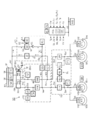
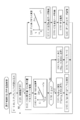
- FIG. 1 is an overall configuration diagram for describing a first embodiment of a brake control device SC of a vehicle according to the present invention. It is a control flow figure for explaining processing of pressure regulation control including regeneration coordination control.
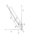
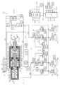
- FIG. 10 is a characteristic diagram for illustrating front-rear distribution of braking force in regeneration coordination control in a vehicle provided with a generator GN on the front wheels WHf. It is a whole block diagram for describing a 2nd embodiment of brake control control equipment SC of a vehicle concerning the present invention. It is the schematic for demonstrating the other structural example of the 1st pressure regulation unit YC.
- FIG. 7 is a characteristic diagram for explaining front-rear distribution of braking force in regeneration coordination control in a vehicle provided with a generator GN on a rear wheel WHr.
- FIG. 6 is a characteristic diagram for explaining front-rear distribution of braking force in regenerative coordinated control in a vehicle provided with front and rear wheels WHf and WHr with generators GNf and GNr.
- each symbol represents a generic name for each of the four wheels. For example, "WH” represents each wheel, and “CW” represents each wheel cylinder.
- the suffixes "f” and “r” added at the end of various symbols are generic symbols indicating which of the front and rear wheels in the two braking systems. Specifically, “f” indicates a front wheel system, and “r” indicates a rear wheel system.
- the front wheel master cylinder valve VMf and the rear wheel master cylinder valve VMr are described.
- the suffixes "f", "r” at the end of the symbol may be omitted.
- each symbol represents a generic name of the two braking systems.
- VM represents a master cylinder valve in the front and rear braking systems.
- the operation of the braking control device SC is in a proper state, and the braking performed by the braking control device SC is referred to as "controlled braking".
- controlled braking When the operation of the braking control device SC is in a malfunctioning state, braking by only the driver's operating force is referred to as “manual braking”. Therefore, in the manual braking, the braking control device SC is not used.
- a first embodiment of a braking control device SC according to the present invention will be described with reference to the overall configuration diagram of FIG.
- the fluid path is a path for moving the braking fluid BF, which is a working fluid of the braking control device, and corresponds to a braking pipe, a flow path of a fluid unit, a hose or the like.
- the inside of the fluid path is filled with the damping fluid BF.
- the side closer to the reservoir RV (the side farther from the wheel cylinder CW) is referred to as “upstream” or “upper”, and the side closer to the wheel cylinder CW (the side farther from the reservoir RV) is It is called “downstream” or “lower.”
- the front wheel system of the two fluid paths is connected to the front wheel cylinders CWi, CWj (also described as “CWf”).
- the rear wheel system of the two fluid paths is connected to rear wheel wheel cylinders CWk, CWl (also referred to as “CWr”). That is, so-called front and rear types (also referred to as “H-type”) are adopted as the fluid paths of two systems.
- the vehicle is a hybrid vehicle or an electric vehicle equipped with an electric motor GN for driving.
- the driving electric motor GN also functions as a generator (energy generator) for energy regeneration.
- the generator GN is provided on the front wheel WHf.
- the wheel provided with the generator GN is referred to as "regenerative wheel WHg”
- the wheel not provided with the generator GN is referred to as "non-regenerative wheel WHt”. Therefore, the front wheel WHf is a regenerative wheel WHg (corresponding to “one side wheel”), and the rear wheel WHr is a non-regenerative wheel WHt (corresponding to “the other side wheel”).
- a vehicle provided with a braking control device SC is provided with a braking operation member BP, a wheel cylinder CW, a reservoir RV, and a wheel speed sensor VW.
- the braking operation member (for example, a brake pedal) BP is a member operated by the driver to decelerate the vehicle.
- the braking torque of the wheel WH is adjusted, and the braking force F (a generic name of Ff and Fr) is generated on the wheel WH.
- a rotating member for example, a brake disc
- a brake caliper is arrange
- the brake caliper is provided with a wheel cylinder CW.
- the pressure (braking fluid pressure) Pw of the braking fluid BF in the wheel cylinder CW is increased, the friction member (for example, the brake pad) is pressed against the rotating member KT. Since the rotating member KT and the wheel WH are fixed to rotate integrally, a braking torque (frictional braking force Fp) is generated on the wheel WH by the frictional force generated at this time.
- the wheel cylinder provided on the regenerative wheel WHg (the wheel having the generator GN) is referred to as “regenerative wheel cylinder CWg”. Further, a wheel cylinder provided on the non-regenerative wheel WHt (wheel having no generator GN) is referred to as "non-regenerative wheel cylinder CWt”. Since the generator GN is provided on the front wheel WHf, the front wheel cylinder CW (CWi, CWj) is the regenerative wheel cylinder CWg, and the rear wheel cylinder CWr (CWk, CWl) is the non-regenerative wheel cylinder CWt.
- the reservoir (atmospheric pressure reservoir) RV is a tank for working fluid, in which the damping fluid BF is stored.
- the lower part of the reservoir RV is a master reservoir chamber Ru (Ruf, Rur) connected to the master cylinder chamber Rm (Rmf, Rmr) by a partition plate SK, and a pressure control reservoir chamber Rd connected to the first pressure control unit YC. It is divided into and.
- Master cylinder CM is mechanically connected to brake operation member BP via a brake rod, a clevis (U-shaped joint), and the like.
- Master cylinder CM is a so-called tandem type having two chambers (fluid pressure chambers) Rmf and Rmr.
- the front wheel master cylinder chamber Rmf is divided by the inner wall (cylindrical surface) of the master cylinder CM, the rear end of the first master piston PSf, and the front end of the second master biston PSr, and the braking operation member BP is not operated. In the case (non-braking time), the front wheel reservoir chamber Ruf is in communication.
- the rear wheel master cylinder chamber Rmr is partitioned by the inner wall (cylindrical surface and bottom surface) of the master cylinder CM and the rear end portion of the second master biston PSr, and is communicated with the rear wheel reservoir chamber Rur when not braking.
- the braking operation member BP When the braking operation member BP is operated, the first and second pistons PSf and PSr in the master cylinder CM are pushed and advanced. By the forward movement, the master cylinder chamber Rm (Rmf, Rmr) is shut off from the reservoir RV (in particular, the master reservoir chamber Ruf, Rur). Furthermore, when the operation of the dynamic operation member BP is increased, the volume of the master cylinder chamber Rm decreases, and the braking fluid BF is pumped from the master cylinder CM toward the wheel cylinder CW.
- RV in particular, the master reservoir chamber Ruf, Rur
- Each wheel WH is provided with a wheel speed sensor VW so as to detect the wheel speed Vw.
- the signal of wheel speed Vw is used for independent braking control of each wheel such as anti-skid control (control to suppress excessive deceleration slip of the wheel), vehicle stabilization control (control to suppress excessive oversteer and understeer behavior), etc. Be done.
- Each wheel speed Vw detected by the wheel speed sensor VW is input to the controller ECU.
- the controller ECU calculates a vehicle speed Vx based on the wheel speed Vw.
- the braking control device SC includes an operation amount sensor BA, an operation switch ST, a stroke simulator SS, a simulator solenoid valve VS, a master cylinder solenoid valve VM, a first pressure regulation unit YC, a separation solenoid valve VC, a second pressure regulation unit YD, , Controller ECU.
- the inside of the braking control device SC is made liquid tight by the braking fluid BF.
- the brake operation member BP is provided with an operation amount sensor BA.
- the operation amount sensor BA detects the operation amount Ba of the braking operation member (brake pedal) BP by the driver.
- a master cylinder hydraulic pressure sensor PM that detects hydraulic pressure (master cylinder hydraulic pressure) Pm in a master cylinder CM as a braking operation amount sensor BA, an operation displacement sensor SP that detects an operation displacement Sp of a braking operation member BP, and braking
- At least one of the operation force sensors FP for detecting the operation force Fp of the operation member BP is employed. That is, at least one of the master cylinder hydraulic pressure Pm, the braking operation displacement Sp, and the braking operation force Fp is detected by the operation amount sensor BA as the braking operation amount Ba.
- the braking operation amount Ba is input to the controller ECU.
- the braking operation member BP is provided with an operation switch ST.
- the operation switch ST detects the presence or absence of the operation of the braking operation member BP by the driver.
- the braking operation switch ST outputs an off signal as the operation signal St.
- an ON signal is output as the operation signal St.
- the braking operation signal St is input to the controller ECU.
- a stroke simulator (simply referred to as “simulator”) SS is provided to generate an operating force Fp on the brake operating member BP.
- a piston and an elastic body are provided inside the simulator SS.
- the braking fluid BF is moved from the master cylinder CM to the simulator SS, and the piston is pushed by the inflowing braking fluid BF.
- a force is applied to the piston by the elastic body in a direction to prevent the inflow of the braking fluid BF.
- the elastic body forms an operating force Fp when the brake operating member BP is operated.
- Master cylinder CM is connected to wheel cylinder CW by master cylinder fluid path HM.
- a master cylinder valve VM is provided in the middle of the master cylinder fluid path HM.
- the master cylinder valve VM is a two-position solenoid valve (also referred to as an "on / off valve") having an open position (communication state) and a closed position (shut off state).
- Master cylinder valve VM is controlled by drive signal Vm from controller ECU.
- the master cylinder valve VM is in the open position, and the master cylinder CM and the wheel cylinder CW are in communication with each other via the master cylinder fluid passage HM.
- the master cylinder valve VM At the time of control braking, the master cylinder valve VM is in the closed position, and the master cylinder CM and the wheel cylinder CW are in the disconnected state (disconnected state).
- the master cylinder valve VM employs a normally open solenoid valve.
- a simulator valve VS is provided between the master cylinder chamber Rm in the master cylinder CM and the simulator SS on the upstream side of the master cylinder valve VM.
- the simulator valve VS is a two-position solenoid valve (on / off valve) having an open position and a closed position.
- the simulator valve VS is controlled by the drive signal Vs from the controller ECU.
- the simulator valve VS is brought into the closed position, and the master cylinder CM and the simulator SS are brought into the disconnected state. In this case, the braking fluid BF from the master cylinder CM is not consumed by the simulator SS.
- the simulator valve VS is in the open position, and the master cylinder CM and the simulator SS are in communication.
- the operation characteristic (the relationship between the operation displacement Sp and the operation force Fp) of the braking operation member BP is formed by the simulator SS.
- the simulator valve VS employs a normally closed solenoid valve. When the volume of master cylinder chamber Rm is sufficiently large, simulator valve VS may be omitted.
- the first pressure regulation unit YC includes a first electric pump DC, a check valve GC, a first pressure regulation valve UC, and a first adjustment hydraulic pressure sensor PC.
- the first electric pump DC is configured by a set of one first electric motor MC and one first fluid pump QC.
- the first electric motor MC and the first fluid pump QC are fixed so that the first electric motor MC and the first fluid pump QC rotate integrally.
- the first electric pump DC (in particular, the first electric motor MC) is a power source for increasing the braking fluid pressure Pw at the time of control braking.
- the electric motor MC is controlled by a controller ECU.
- a three-phase brushless motor is employed as the first electric motor MC.
- the brushless motor MC is provided with a rotation angle sensor KA for detecting the rotor position (rotation angle) Ka.
- the switching elements of the bridge circuit are controlled based on the rotation angle (actual value) Ka, and the electric motor MC is driven. That is, the direction (that is, the excitation direction) of the energization amounts of the coils of each of the three phases (U phase, V phase, and W phase) is sequentially switched, and the brushless motor MC is rotationally driven.
- the drive circuit DR is provided with an energization amount sensor that detects an actual energization amount Ia (a generic name of each phase) of the electric motor MC.
- a current sensor is provided as an energization amount sensor, and a current Ia supplied to the electric motor MC is detected.
- the suction port Qs of the first fluid pump QC is connected to the reservoir RV (in particular, the pressure control reservoir chamber Rd) via the reservoir fluid path HR.
- a pressure control fluid passage HC is connected to the discharge port Qt of the fluid pump QC.
- the electric pump DC in particular, the fluid pump QC
- the braking fluid BF is sucked from the reservoir fluid passage HR through the suction port Qs and is discharged from the discharge port Qt to the pressure regulating fluid passage HC.
- a gear pump is employed as the first fluid pump QC.
- a check valve GC (also referred to as a "check valve”) is interposed in the pressure control fluid passage HC.
- a check valve GC is provided near the discharge portion Qt of the fluid pump QC.
- the braking fluid BF can move from the reservoir fluid passage HR to the pressure regulating fluid passage HC, but moves from the pressure regulating fluid passage HC to the reservoir fluid passage HR (ie, braking) Backflow of fluid BF is prevented. That is, the electric pump DC is rotated only in one direction.
- the first pressure regulating valve UC is connected to the pressure regulating fluid passage HC and the reservoir fluid passage HR.
- the first pressure regulator valve UC is a linear solenoid valve (a “proportional valve” or a “differential pressure valve”) in which the valve opening amount (lift amount) is continuously controlled based on the energized state (for example, supplied current). Say).
- the pressure regulator valve UC is controlled by the controller ECU based on the drive signal Uc.
- a normally open solenoid valve is employed as the pressure regulating valve UC.
- the braking fluid BF is pumped from the reservoir fluid passage HR through the suction port Qs of the first fluid pump QC and is discharged from the discharge port Qt. Then, the braking fluid BF passes through the check valve GC and the pressure regulating valve UC, and is returned to the reservoir fluid path HR.
- the reservoir fluid passage HR and the pressure regulating fluid passage HC form a reflux passage (a fluid passage in which the flow of the braking fluid BF returns to the original flow again), and a check valve GC is formed in the reflux passage. And a pressure regulating valve UC is interposed.
- the braking fluid BF is returned in the order of “HR ⁇ QC (Qs ⁇ Qt) ⁇ GC ⁇ UC ⁇ HR” as indicated by the broken arrow (A). ing.
- the hydraulic pressure (adjusted hydraulic pressure) Pc in the pressure regulating fluid passage HC is low, substantially “0 (atmospheric pressure)" It is.
- the adjusted hydraulic pressure Pc is increased.
- the return of the braking fluid BF formed by the electric pump DC is adjusted by the pressure adjustment valve UC, and an adjusted fluid pressure (corresponding to “first fluid pressure”) Pc is generated.
- the pressure control system is called "reflux type”.
- a first adjustment hydraulic pressure sensor PC is provided in the pressure regulation fluid passage HC (particularly, between the check valve GC and the pressure regulation valve UC) so as to detect the adjustment hydraulic pressure Pc.
- the pressure control fluid passage HC is branched into a front wheel pressure control fluid passage HCf and a rear wheel pressure control fluid passage HCr at a branch portion Bn.
- the front wheel pressure adjustment fluid passage HCf is connected to the front wheel master cylinder fluid passage HMf at the downstream portion Bmf of the front wheel master cylinder valve VMf.
- the rear wheel pressure adjustment fluid path HCr is connected to the rear wheel master cylinder fluid path HMr at a downstream portion Bmr of the rear wheel master cylinder valve VMr.
- the adjusted hydraulic pressure Pc is introduced to the front wheel and rear wheel hole cylinders CWf and CWr via the front wheel, rear wheel pressure adjustment fluid passages HCf and HCr, and the front wheel and rear wheel master cylinder fluid passages HMf and HMr. . That is, the braking fluid BF is pressurized at the downstream portion of the master cylinder CM by the first pressure adjustment unit YC.
- the pressurization system is referred to as "master cylinder downstream pressurization".
- Separation valves VCf and VCr are provided in the middle of the pressure control fluid passages HCf and HCr.
- the separation valve VC is a two-position solenoid valve (on / off valve) having an open position and a closed position.
- the separation valve VC is controlled by a drive signal Vc from the controller ECU.
- the separation valve VC is in the closed position, and the movement of the braking fluid BF from the master cylinder CM to the first pressure regulating unit YC (particularly, pressure regulating valve UC) is blocked. Therefore, the braking fluid BF pumped from the master cylinder CM at the time of manual braking is introduced into the wheel cylinder CW.
- the separation valve VC is in the open position. At this time, since the master cylinder valve VM is in the closed position, the adjusted hydraulic pressure Pc is introduced (supplied) from the first pressure adjustment unit YC to the wheel cylinder CW.
- a normally closed solenoid valve is employed as the separation valve VC.
- the generator GN is provided on the front wheel WHf, but the braking system for the rear wheel WHr not provided with the generator GN is provided with a second pressure adjustment unit YD.
- the second pressure regulation unit YD is provided on the downstream side of the rear wheel master cylinder valve VMr (for example, between the portion Bmr and the rear wheel hole cylinder CWr).
- the adjustment hydraulic pressure (corresponding to the “first hydraulic pressure”) Pc is controlled by the second pressure regulation unit YD so that the distribution between the front wheel braking force Ff and the rear wheel braking force Fr is optimized.
- the output hydraulic pressure Ppr is added to the rear wheel wheel cylinder CWr. At this time, the adjusted hydraulic pressure Pc is applied to the front wheel wheel cylinder CWf. Therefore, the rear wheel braking hydraulic pressure Pwr is larger than the front wheel braking hydraulic pressure Pwf.
- the pressure regulation control by the second pressure regulation unit YD is referred to as “independent control” in regeneration coordination control. That is, in a vehicle having the generator GN on the front wheel WHf, the independent control is to apply the adjusted hydraulic pressure Pc to the front wheel cylinder CWf and the output hydraulic pressure Ppr increased from the adjusted hydraulic pressure Pc to the rear wheel wheel cylinder CWr. By being applied, the front wheel system and the rear wheel system are controlled independently.
- the second pressure regulation unit YD is configured of a second electric pump DL, a rear wheel second pressure regulation valve UPr, and a rear wheel output hydraulic pressure sensor PPr.
- the second electric pump DL is configured by a set of a second electric motor ML and a second fluid pump QL. Also in the second electric pump DL, the second electric motor ML and the second fluid pump QL are fixed so as to rotate integrally as in the first electric pump DC.
- the second electric pump DL (in particular, the second electric motor ML) is a power source for increasing the adjusted hydraulic pressure Pc to the output hydraulic pressure Ppr.
- the electric motor ML is controlled by the controller ECU based on the drive signal Ml.
- the suction port of the second fluid pump QLr is connected to the upstream portion Bor of the pressure regulating valve UPr in the rear wheel master cylinder fluid passage HMr.
- the discharge port of the second fluid pump QLr is connected to the downstream portion Bpr of the pressure regulating valve UPr in the rear wheel master cylinder fluid passage HMr.
- a check valve is provided at the discharge portion of the fluid pump QLr to prevent backflow of the braking fluid BF.
- the second pressure regulating valve (also referred to as a “charge valve”) UPr for the rear wheel is normally controlled such that the valve opening amount is continuously controlled based on the amount of energization (for example, supply current). It is an open linear solenoid valve (proportional valve).
- the rear wheel charge valve UPr is controlled by the controller ECU based on the drive signal Up.
- the hydraulic pressure (output hydraulic pressure) Ppr downstream of the rear wheel charge valve UPr is the adjustment fluid Match the pressure Pc.
- a rear wheel output hydraulic pressure sensor PPr is provided downstream of the rear wheel charge valve UPr so as to detect the output hydraulic pressure Ppr.
- An electronic control unit also referred to as a "controller” ECU is configured of an electric circuit board on which a microprocessor MP or the like is mounted, and a control algorithm programmed in the microprocessor MP.
- UC and UPr are controlled. Specifically, drive signals Vm, Vs, Vc, Uc and Upr for controlling the various solenoid valves VM, VS, VC, UC and UPr are calculated based on a control algorithm in the microprocessor MP.
- drive signals Mc and Ml for controlling the electric motors MC and ML are calculated. Then, based on these drive signals Vm, Vs, Vc, Uc, Upr, Mc, Ml, the solenoid valves VM, VS, VC, UC, UPr and the electric motors MC, ML are driven.
- the controller ECU is connected to another electronic control unit (controller) via a network via the in-vehicle communication bus BS.
- the controller ECU transmits the regeneration amount Rg (target value) to the drive controller ECD so as to execute the regeneration coordination control.
- the “regeneration amount Rg” is a state amount representing the size of the regenerative brake generated by the drive motor (also the generator for regeneration) GN. Electric power is supplied to the controller ECU from the on-board generator AL and the storage battery BT.
- the controller ECU is provided with a drive circuit DR to drive the solenoid valves VM, VS, VC, UC, UPr and the electric motors MC, ML.
- a bridge circuit is formed by switching elements (power semiconductor devices such as MOS-FETs and IGBTs) so as to drive the electric motor MC.
- the energization states of the switching elements are controlled based on the motor drive signals Mc and Ml, and the outputs of the electric motors MC and ML are controlled.
- the excitation states thereof are controlled based on the drive signals Vm, Vs, Vc, Uc and Upr so as to drive the solenoid valves VM, VS, VC, UC and UPr.
- the "pressure regulation control” controls the drive of the first and second electric motors MC and ML and the first and second pressure regulation valves UC and UPr for adjusting the regulated hydraulic pressure Pc and the output hydraulic pressure Ppr. It is.
- the control algorithm is programmed in the controller ECU.
- step S110 the braking operation amount Ba, the operation signal St, the adjusted hydraulic pressure Pc, the output hydraulic pressure Pp, the rotation angle Ka, and the wheel speed Vw are read.
- the operation amount Ba is detected by an operation amount sensor BA (master cylinder hydraulic pressure sensor PM, operation displacement sensor SP, etc.).
- the operation signal St is detected by an operation switch ST provided on the braking operation member BP.
- the adjusted hydraulic pressure Pc is detected by an adjusted hydraulic pressure sensor PC provided in the pressure control fluid passage HC.
- the rear wheel output hydraulic pressure Ppr is detected by a rear wheel output hydraulic pressure sensor PPr.
- the motor rotation angle Ka is detected by a rotation angle sensor KA provided to the electric motor MC.
- the wheel speed Vw is detected by a wheel speed sensor VW provided on each wheel WH.
- step S120 it is determined whether or not the braking operation is in progress based on at least one of the braking operation amount Ba and the braking operation signal St. For example, if the operation amount Ba is equal to or larger than the predetermined value bo, step S120 is affirmed, and the process proceeds to step S130. On the other hand, if “Ba ⁇ bo”, step S120 is denied, and the process returns to step S110.
- the predetermined value bo is a preset constant corresponding to the play of the braking operation member BP. If the operation signal St is on, the process proceeds to step S130. If the operation signal St is off, the process returns to step S110.
- step S130 the normally open master cylinder valve VM is brought into the closed position, and the normally closed separation valve VC is brought into the open position. Also, the normally closed simulator valve VS is in the open position. As a result, the master cylinder CM is separated from the wheel cylinder CW, and the wheel cylinder CW is made ready for pressurization by the first pressure regulation unit YC. Further, the simulator SS is connected to the master cylinder chamber Rm, and the operation characteristic of the braking operation member (brake pedal) BP is formed by the simulator SS.
- step S130 the first pressure adjustment unit YC is driven on standby so that the second pressure adjustment unit YD can suction the braking fluid BF. Specifically, the first electric pump DC is rotated so that the adjusted hydraulic pressure Pc is slightly higher than the atmospheric pressure to such an extent that the adjusted hydraulic pressure Pc does not affect the deceleration of the vehicle, and the first pressure regulating valve UC is throttled. Be At step S130, the first pressure adjustment unit YC is put into a so-called standby state.
- a target deceleration Gt is calculated based on the operation amount Ba.
- the target deceleration Gt is a target value of deceleration at deceleration of the vehicle.
- the target deceleration Gt is determined to be “0” in the range from “0” to the predetermined value bo according to the calculation map Zgt, and the manipulation amount Ba increases when the operation amount Ba is the predetermined value bo or more. Along with this, it is calculated so as to monotonically increase from "0".
- step S150 based on the target deceleration Gt, it is determined whether or not the target deceleration Gt is equal to or greater than a predetermined regeneration amount rg.
- the predetermined regeneration amount rg is a threshold value for vehicle deceleration that can be achieved by regenerative braking.
- the predetermined regeneration amount rg is preset as a constant. Further, the predetermined amount of regeneration rg may be set based on the state of the regeneration generator GN or the storage battery BT. If “Gt ⁇ rg” and step S140 is negative, the process proceeds to step S160. On the other hand, if “Gt ⁇ rg” is satisfied, the process proceeds to step S180.
- step S170 the target fluid pressures Ptf and Ptr of the front and rear wheels are calculated to "0". That is, the target value of the adjusted hydraulic pressure Pc is determined to be "0". In this case, friction braking is not employed for vehicle deceleration, and the target deceleration Gt is achieved only by regenerative braking.
- the target fluid pressure Pt (Ptf, Ptr) is a target value of fluid pressure to be achieved by friction braking.
- a target rotation speed Nt is calculated based on the target fluid pressure Pt (in particular, the front wheel target fluid pressure Ptf).
- the target rotation speed Nt is a target value of the rotation speed of the electric motor MC.
- the target rotational speed Nt is calculated to monotonously increase as the target fluid pressure Pt increases in accordance with the operation map Znt.
- the adjusted hydraulic pressure Pc is generated by the orifice effect of the pressure regulation valve UC. Since a certain amount of flow rate is required to obtain the orifice effect, the target rotation speed Nt is provided with a predetermined lower limit rotation speed no.
- the lower limit rotational speed no is a minimum required value (preset constant) in hydraulic pressure generation.
- the target rotation speed Nt may be directly calculated based on the braking operation amount Ba. In any case, the target rotational speed Nt is determined based on the braking operation amount Ba.
- step S210 servo control based on the number of revolutions (control to make the actual value follow the target value quickly) is executed in the first electric motor MC.
- rotational speed servo control rotational speed feedback control of the electric motor MC is executed based on the target rotational speed Nt and the actual rotational speed Na.
- the rotation angle Ka is time-differentiated based on the motor rotation angle (detection value) Ka, and the motor rotation speed (the actual rotation number per unit time) Na is calculated.
- the number of rotations of the electric motor MC is used as a control variable, and the amount of energization (for example, supply current) to the electric motor MC is controlled.
- the rotational speed deviation hN becomes "0" (that is, the actual value Na is the target value Nt )
- the amount of energization of the electric motor MC is finely adjusted.
- the predetermined value nx is a constant set in advance.
- step S220 servo control based on fluid pressure is executed in the first pressure regulating valve UC.
- fluid pressure servo control fluid pressure feedback control of the pressure adjustment valve UC is executed based on the front wheel target fluid pressure Ptf and the adjusted fluid pressure Pc (detection value of the pressure adjustment fluid pressure sensor PC).
- the pressure Pc of the braking fluid BF in the pressure control fluid passage HC is used as a control variable to control the amount of current supplied to the normally open first linear pressure control valve UC.
- the hydraulic pressure deviation hP becomes "0" (that is, the adjusted hydraulic pressure Pc approaches the front wheel target hydraulic pressure Ptf) Yes, the amount of current supplied to the pressure regulator valve UC is adjusted.
- the amount of energization of the pressure regulator valve UC is increased, and the amount of opening of the pressure regulator valve UC is decreased.
- the predetermined value px is a constant set in advance.
- step S230 the second electric motor ML is driven by the controller ECU, and the braking fluid BF is discharged from the upstream side to the downstream side of the rear wheel charge valve UPr by the second fluid pump QLr.
- the upstream hydraulic pressure (adjusted hydraulic pressure) Pc and the downstream hydraulic pressure of the charge valve UP (Output hydraulic pressure) Pp is approximately equal.
- the regenerative braking force Fgf acts on the front wheel WHf.
- the friction braking force Fp is adjusted so that the distribution of the braking forces of the front and rear wheels is optimized.
- servo control hydraulic pressure servo control
- hydraulic pressure feedback control of the rear wheel charge valve UPr is executed so that the rear wheel output hydraulic pressure Ppr is adjusted to be increased from the adjusted hydraulic pressure Pc.
- a deviation hQ between the rear wheel target hydraulic pressure Ptr and the actual rear wheel output hydraulic pressure Ppr (the detected value of the rear wheel output hydraulic pressure sensor PPr) is calculated.
- the amount of current supplied to the rear wheel charge valve UPr is adjusted so that the hydraulic pressure deviation hQ becomes "0" and the rear wheel output hydraulic pressure Ppr approaches the rear wheel target hydraulic pressure Ptr. .
- the rear wheel output hydraulic pressure sensor PPr may be omitted.
- slip servo control is executed with the wheel deceleration slip (also simply referred to as "wheel slip") Sw as a state variable.
- the servo control based on the wheel slip Sw has a proportional relationship between the wheel slip Sw and the wheel braking force F when the wheel deceleration slip Sw is not excessive (ie, when the wheel slip Sw is within a predetermined range).
- the vehicle speed Vw, the wheel speed Vx, and the deviation hV are used as the wheel slip (state quantity) Sw.
- a wheel slip ratio obtained by dividing the deviation hV by the vehicle speed Vx may be employed as the wheel slip Sw.
- step S240 the rear wheel target hydraulic pressure Ptr is converted into a rear wheel target slip Str. Further, the actual rear wheel slip Swr is calculated based on the rear wheel speed Vwr and the vehicle body speed Vx. Then, the amount of current supplied to the rear wheel charge valve UPr is adjusted so that the actual rear wheel slip Swr (actual value) approaches the rear wheel target slip Str (target value) and matches.
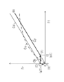
- the front-rear distribution of the braking force F in regenerative coordinated control will be described in association with the calculation processing shown in FIG. 2.
- the regeneration generator GN is provided on the front wheel WHf, and the regenerative braking force Fgf acts on the front wheel WHf in addition to the friction braking force Fpf.
- the front wheel WHf corresponds to the regenerative wheel WHg having the generator GN.
- the generator GN is not provided on the rear wheel WHr, the regenerative braking force Fgr does not act on the rear wheel WHr, and only the friction braking force Fpr acts. That is, the rear wheel WHr corresponds to the non-regenerative wheel WHt having no generator GN.
- a characteristic Ca indicated by an alternate long and short dash line represents so-called ideal braking force distribution in which fluctuations in the ground contact load (vertical force) of the front and rear wheels accompanying deceleration of the vehicle are taken into consideration.
- the braking forces Ff and Fr of the front and rear wheels are proportional to the dynamic ground contact load (vertical force) in consideration of the vehicle deceleration. Therefore, in the ideal distribution characteristic Ca, when antiskid control is not performed, the front wheels WHf and the rear wheels WHr simultaneously lock the wheels even on a road surface having different friction coefficients, and the friction braking force is maximized.
- the characteristic Cb is an ideal distribution characteristic within the range of normal braking (in the range excluding the area generating the maximum braking force) so that the rear wheel WHr does not lock the wheel ahead of the front wheel WHf.
- the pressure receiving area of the wheel cylinder CW, the effective braking radius of the rotating member KT, and the friction coefficient of the friction material are set so as to be smaller than Ca.
- the braking force distribution control (so-called EBD control) is executed based on the wheel speed Vw so that the deceleration slip of the rear wheel WHr does not become larger than the deceleration slip of the front wheel WHf. .
- step S150 the determination condition of step S150 is satisfied, and the processes of step S180 and step S190 are performed.
- the rear wheel target hydraulic pressure Ptr is determined to be “the first predetermined hydraulic pressure p1 corresponding to the first predetermined force r1” (see the transition from the point (C) to the point (D)).
- the front wheel target fluid pressure Ptf is monotonously increased from “0” as the operation amount Ba increases so that the friction braking force Fp increases along the characteristic Cb.
- the rear wheel target hydraulic pressure Ptr is calculated so as to monotonously increase from the “first predetermined hydraulic pressure p1 corresponding to the first predetermined force r1” as the operation amount Ba increases.
- the characteristic Cx characteristics (O)-(C)-(D)-(B)
- step S200 and S210 the first electric motor MC is driven by the rotation speed servo control, and the return of the braking fluid BF including the first fluid pump QC and the first pressure regulating valve UC is formed. Then, in step S220, the hydraulic pressure servo control based on the target hydraulic pressure Pt (in particular, the front wheel target hydraulic pressure Ptf) is executed, and the adjusted hydraulic pressure Pc (the detection value of the adjusted hydraulic pressure sensor PC) becomes the front wheel target hydraulic pressure Ptf.
- the target hydraulic pressure Pt in particular, the front wheel target hydraulic pressure Ptf
- the second electric motor ML is rotationally driven to form a return of the braking fluid BF including the second rear wheel fluid pump QLr and the rear wheel charge valve (second rear wheel pressure adjustment valve) UPr. Be done.
- the rear wheel target slip Str corresponding to the rear wheel target hydraulic pressure Ptr is calculated in step S240, and the slip based on the rear wheel target slip Str Servo control is performed.
- the vehicle speed Vx is calculated based on the wheel speed Vw (the detected value of the wheel speed sensor VW), and based on the vehicle speed Vx and the rear wheel speed Vwr (the detected value of the rear wheel speed sensor VWr)
- the actual rear wheel slip (actual value) Swr is calculated.
- the rear wheel charge valve UPr is controlled such that the rear wheel actual slip Swr approaches the rear wheel target slip Str.
- the output hydraulic pressure Ppr is increased from the adjusted hydraulic pressure Pc and adjusted.
- the rear wheel braking force Fr in the characteristic Cc is smaller than the rear wheel braking force Fr of the ideal distribution characteristic Ca. Therefore, in the characteristic Cc, the vehicle stability is ensured, but the rear wheel braking force Fr can not be sufficiently utilized.
- the adjusted hydraulic pressure Pc is increased and adjusted by the rear wheel charge valve UPr, and the hydraulic pressure (output hydraulic pressure) of the braking system of the front and rear wheels Ppf and Ppr are controlled independently.
- the braking forces Ff and Fr of the front and rear wheels are suitably secured, and the amount of energy that can be regenerated can be sufficiently secured after the vehicle stability is maintained.
- a second embodiment of a braking control device SC according to the present invention will be described with reference to the overall configuration diagram of FIG.
- the tandem type is adopted as the form of the master cylinder CM.
- a "reflow type” one as a pressure control system of the first pressure regulation unit YC and a "master cylinder downstream pressure” one as a pressure system (pressure part) were adopted.
- a "single type” is adopted as the master cylinder CM, and an accumulator is used as the first pressure control unit YC (referred to as "accumulator type”).
- pressurization by the first pressure regulation unit YC is performed by introducing the adjusted hydraulic pressure Pc to the back surface of the master cylinder CM (a portion opposite to the master cylinder chamber Rm) (“master cylinder back pressure application Pressure)).
- a fluid unit for realizing vehicle stabilization control is adopted as the second pressure regulation unit YD.
- the lower fluid unit YL including the second pressure regulation unit YD is provided separately from the upper fluid unit YU including the first pressure regulation unit YC.
- the upper fluid unit YU is controlled by the upper controller ECU, and the lower fluid unit YL is controlled by the lower controller ECL different from the upper controller ECU.
- the two controller ECUs ECL are communicably connected by a communication bus BS. The differences will be mainly described below.
- suffixes “f” and “r” at the end of the symbol are inclusive symbols indicating which system of the front and rear wheels relates to the two systems of fluid paths (moving path of the damping fluid BF), “f "Indicates a front wheel system, and” r “indicates a rear wheel system. When the subscripts "f” and “r” are omitted, they represent two systems collectively. In each fluid passage, “upstream (or upper)” is closer to the reservoir RV, and “downstream (or lower)” is closer to the wheel cylinder CW.
- the vehicle is provided with a steering angle sensor SA to detect the steering angle Sa of the steering wheel.
- a yaw rate sensor YR is provided to detect a yaw rate (yaw angular velocity) Yr of the vehicle.
- a longitudinal acceleration sensor GX and a lateral acceleration sensor GY are provided to detect longitudinal acceleration (longitudinal acceleration) Gx and lateral acceleration (lateral acceleration) Gy of the vehicle.
- the detected steering angle Sa, yaw rate Yr, longitudinal acceleration Gx, and lateral acceleration Gy are input to the lower controller ECL.
- the wheel speed Vw detected by the wheel speed sensor VW is input to the lower controller ECL.
- a vehicle speed Vx is calculated based on the wheel speed Vw.
- the braking control device SC is configured by an upper fluid unit YU closer to the master cylinder CM and a lower fluid unit YL closer to the wheel cylinder CW.
- the upper fluid unit YU is a fluid unit controlled by the upper controller ECU and included in the braking control device SC.
- the upper fluid unit YU is configured of a master unit YM, a first pressure adjustment unit YC, a regeneration coordination unit YK, and an upper controller ECU in addition to the operation amount sensor BA and the operation switch ST.
- the operation amount sensor BA detects the operation amount Ba of the braking operation member (brake pedal) BP by the driver.
- an operation displacement sensor SP for detecting an operation displacement Sp and an operation force sensor FP for detecting an operation force Fp are provided.
- a simulator hydraulic pressure sensor PS is provided so as to detect the hydraulic pressure (simulator hydraulic pressure) Ps in the stroke simulator SS.
- the master cylinder hydraulic pressure sensor PM is not employed.
- the fluid pressure (front wheel braking fluid pressure) Pwf in the front wheel wheel cylinder CWf is adjusted by the master unit YM via the master cylinder chamber Rm.
- the master unit YM is configured to include a master cylinder CM, a master piston PM, and a master elastic body SM.
- Master cylinder CM is a cylinder member having a bottom.
- the master piston PM is a piston member inserted inside the master cylinder CM, and is movable in conjunction with the operation of the braking operation member BP.
- the inside of the master cylinder CM is divided into three chambers (fluid pressure chambers) Rm, Rs and Ro by a master piston PM.
- a groove is formed in the first inner peripheral portion Mc of the master cylinder CM, and two seals SL are fitted in the groove.
- An outer peripheral portion (outer peripheral cylindrical surface) Mp of the master piston PM and a first inner peripheral portion (inner peripheral cylindrical surface) Mc of the master cylinder CM are sealed by the two seals SL.
- Master piston PM can move smoothly along central axis Jm of master cylinder CM.
- the master cylinder chamber (simply referred to as “master chamber”) Rm is defined by “the first inner peripheral portion Mc, the first bottom portion (bottom surface) Mu” of the master cylinder CM, and the first end Mv of the master piston PM. It is a divided hydraulic chamber.
- a master cylinder fluid passage HM is connected to the master chamber Rm, and is ultimately connected to the front wheel wheel cylinder CWf via the lower fluid unit YL.
- the master piston PM is provided with a flange portion Tm.
- the inside of the master cylinder CM is divided into a servo hydraulic pressure chamber (also simply referred to as a “servo chamber”) Rs and a rear hydraulic pressure chamber (also simply referred to as a “rear chamber”) Ro by the flange portion Tm.
- a seal SL is provided on the outer peripheral portion of the collar portion Tm, and the collar portion Tm and the second inner peripheral portion Md of the master cylinder CM are sealed (sealed).
- the servo chamber Rs is a hydraulic pressure chamber partitioned by "the second inner peripheral portion Md and the second bottom portion (bottom surface) Mt of the master cylinder CM" and the first surface Ms of the flange portion Tm of the master piston PM.
- the master chamber Rm and the servo chamber Rs are disposed to face each other with the master piston PM (in particular, the flange portion Tm) interposed therebetween.
- a front wheel pressure control fluid passage HCf is connected to the servo chamber Rs, and an adjusted hydraulic pressure Pc is introduced from the first pressure control unit YC. That is, the "master cylinder back pressure type" is adopted at the pressure portion.
- the rear chamber (rear hydraulic pressure chamber) Ro is a hydraulic pressure chamber defined by the second inner peripheral portion Md of the master cylinder CM, the stepped portion Mz, and the second surface Mo of the flange portion Tm of the master piston PM. It is.
- the rear hydraulic pressure chamber Ro is sandwiched between the master hydraulic pressure chamber Rm and the servo hydraulic pressure chamber Rs in the direction of the central axis Jm and is located between them.
- a simulator fluid passage HS is connected to the rear chamber Ro. The amount of damping fluid BF in the upper fluid unit YU is adjusted by the rear chamber Ro.
- the first end Mv of the master piston PM is provided with a recess Mx.
- a master elastic body (e.g., a compression spring) SM is provided between the recess Mx and the first bottom Mu of the master cylinder CM.
- Master elastic body SM presses master piston PM against second bottom Mt of master cylinder CM in the direction of central axis Jm of master cylinder CM.
- the stepped portion My of the master piston PM abuts on the second bottom portion Mt of the master cylinder CM.
- the position of the master piston PM in this state is referred to as "the initial position of the master unit YM".
- the master cylinder CM is provided with a through hole Ac.
- the through hole Ac is connected to the master reservoir chamber Ru via the replenishment fluid passage HU.
- a through hole Ap is provided in the vicinity of the first end Mv of the master piston PM.
- the master chamber Rm has an urging force Fb (referred to as “retraction force”) in the reverse direction Hb along the central axis Jm by the internal pressure (“master cylinder hydraulic pressure”, also referred to as “master fluid pressure”) Pm.
- the pressure receiving area rs of the first surface Ms of the flange portion Tm (that is, the pressure receiving area of the servo chamber Rs) is the pressure receiving area of the first end Mv of the master piston PM (that is, the pressure receiving area of the master chamber Rm) rm It is set to be equal.
- the hydraulic pressure Pc introduced into the servo chamber Rs (as a result, the servo hydraulic pressure Pv) and the hydraulic pressure Pm in the master chamber Rm are the same in the steady state.
- the adjusted hydraulic pressure Pc is increased by the first pressure control unit YC.
- the adjusted hydraulic pressure Pc is introduced into the servo chamber Rs, and the hydraulic pressure (servo hydraulic pressure) Pv in the servo chamber Rs is increased.
- the master piston PM is moved along the central axis Jm.
- the through hole Ap passes the seal SL by the movement in the forward direction Ha, the master chamber Rm is shut off from the reservoir RV (in particular, the master reservoir chamber Ru).
- the volume of the master chamber Rm decreases, and the braking fluid BF is pumped from the master cylinder CM toward the front wheel cylinder CWf with the master hydraulic pressure Pm.
- the braking operation member BP is not operated, the position (initial position) where the master piston PM (particularly, the stepped portion My) contacts the second bottom Mt of the master cylinder CM by the elastic force of the compression spring SM. Will be returned to
- the first pressure adjustment unit YC (accumulator type)
- the fluid pressure Pm in the master chamber Rm and the fluid pressure (rear wheel braking fluid pressure) Pwr in the rear wheel wheel cylinder CWr are adjusted by the first pressure adjustment unit YC.
- the first pressure regulation unit YC includes an electric pump DZ, an accumulator AZ, an accumulator hydraulic pressure sensor (also referred to as an “accumulated pressure sensor”) PZ, an increase pressure regulation valve UA, a decrease pressure regulation valve UB, and an adjusted hydraulic pressure sensor PC. Ru.
- the first pressure regulation unit YC is an "accumulator type" in which an accumulator is used.
- the first pressure regulating unit YC is provided with a pressure-accumulated electric pump DZ so that the pressurized braking fluid BF is stored in the accumulator AZ.
- the pressure accumulation electric pump DZ is configured by a set of one pressure accumulation electric motor MZ and one pressure accumulation fluid pump QZ. In the pressure accumulation electric pump DC, the electric motor MZ and the fluid pump QZ are fixed so that the electric motor MZ and the fluid pump QZ rotate integrally.
- the accumulator electric pump DZ (in particular, the accumulator electric motor MZ) is a power source for maintaining the hydraulic pressure (accumulator hydraulic pressure) Pz in the accumulator AZ at a high pressure.
- the accumulator electric motor MZ is rotationally driven by the controller ECU. For example, a motor with a brush is employed as the electric motor MZ.
- the braking fluid BF discharged from the pressure accumulation fluid pump QZ is stored in the accumulator AZ.
- An accumulator fluid path HZ is connected to the accumulator AZ, and the accumulator AZ and the increase pressure regulator valve UA are connected.
- An accumulator sensor PZ is provided in the accumulator fluid passage HZ so as to detect the hydraulic pressure (accumulator hydraulic pressure) Pz accumulated in the accumulator AZ.
- a check valve GZ is provided at the discharge portion of the pressure accumulation fluid pump QZ so that the braking fluid BF does not reversely flow from the accumulator AZ.
- the controller ECU controls the accumulator electric pump DZ (in particular, the accumulator electric motor MZ) so that the accumulator hydraulic pressure Pz is maintained within a predetermined range. Specifically, when the accumulator hydraulic pressure Pz is less than the lower limit value (predetermined value) pl, the electric motor MZ is driven at a predetermined rotation speed. Further, when the accumulator hydraulic pressure Pz is equal to or higher than the upper limit value (predetermined value) pu, the electric motor MZ is stopped.
- the lower limit value pl and the upper limit value pu are predetermined constants set in advance, and have a relationship of “pl ⁇ pu”. Therefore, the hydraulic pressure Pz in the accumulator AZ is maintained in the range from the lower limit value pl to the upper limit value pu.
- the first pressure regulation unit YC is provided with a normally closed increase pressure regulation valve UA and a normally open decrease pressure regulation valve UB.
- a pressure control fluid passage HC connects between the increase pressure control valve UA and the decrease pressure control valve UB.
- the decrease pressure control valve UB is connected to the reservoir fluid path HR.
- the increase and decrease pressure adjustment valves UA and UB are linear solenoid valves (proportional valves) whose valve opening amount is continuously controlled based on the amount of electric current (for example, supply current).
- the pressure regulating valves UA, UB are controlled by the controller ECU based on the drive signals Ua, Ub.
- the increase pressure regulating valve UA is energized, and the braking fluid BF flows from the accumulator AZ into the pressure regulating fluid path HC via the accumulator fluid path HZ. Be done. Further, based on the adjusted hydraulic pressure Pc (actual value), the reduction pressure regulating valve UB is energized to adjust the adjusted hydraulic pressure Pc. As in the first embodiment, an adjusted hydraulic pressure sensor PC is provided to detect the adjusted hydraulic pressure Pc.
- the pressure control fluid passage HC is branched (split) into the front wheel pressure control fluid passage HCf and the rear wheel pressure control fluid passage HCr at a branch portion Bn.
- the front wheel pressure adjustment fluid passage HCf is connected to the servo chamber Rs, and the adjusted hydraulic pressure Pc is applied to the servo chamber Rs.
- the rear wheel pressure adjustment fluid path HCr is connected to the lower fluid unit YL, and finally to the rear wheel wheel cylinder CWr (CWk, CWl). Therefore, the adjusted hydraulic pressure Pc is applied to the rear wheel wheel cylinder CWr.
- the fluid pressure Pwr of the rear wheel wheel cylinder CWr is directly controlled by the first pressure regulation unit YC without intervention of the master cylinder CM. That is, a single type is adopted as the master cylinder CM. Therefore, the dimension in the direction of central axis Jm of master cylinder CM can be shortened.
- the regenerative coordination unit YK achieves coordinated control of friction braking and regenerative braking. That is, although the braking operation member BP is operated by the regenerative cooperation unit YK, a state in which the braking fluid pressure Pw is not generated may be formed.
- the regeneration coordination unit YK is configured of an input cylinder CN, an input piston PN, an input elastic body SN, a first on-off valve VA, a second on-off valve VB, a stroke simulator SS, and a simulator hydraulic pressure sensor PS.
- the input cylinder CN is a cylinder member fixed to the master cylinder CM and having a bottom.
- the input piston PN is a piston member inserted inside the input cylinder CN.
- the input piston PN is mechanically connected to the braking operation member BP via a clevis (U-shaped link) so as to interlock with the braking operation member BP.
- the input piston PN is provided with a flange portion Tn.
- An input elastic body (e.g., a compression spring) SN is provided between a mounting surface of the input cylinder CN to the master cylinder CM and the flange portion Tn of the input piston PN.
- the input elastic body SN presses the flange Tn of the input piston PN against the bottom of the input cylinder CN in the direction of the central axis Jm.
- the gap Ks between the master piston PM (especially, the end face Mq) and the input piston PN (especially, the end face Rv) is made a predetermined distance ks (referred to as "initial gap") inside the input cylinder CN.
- the master piston PM and the input piston PN are separated by a predetermined distance ks ing.
- the predetermined distance ks corresponds to the maximum value of the regeneration amount Rg.
- the diameter dm of the master piston PM (end Mq) in the input cylinder CN is set to be equal to the diameter dn of the input piston PN entering the input cylinder CN when the braking operation member BP is operated. Ru. That is, the cross-sectional area am by the diameter dm matches the cross-sectional area an by the diameter dn.
- the manual braking is realized by fluid lock of the inside of the input cylinder CN.
- each piston PN, PM is moved in the forward direction Ha.
- the input cylinder CN is connected to the reservoir RV (in particular, the pressure control reservoir chamber Rd) via the second reservoir fluid path HT.
- the second reservoir fluid passage HT can share a portion with the first reservoir fluid passage HR.
- the fluid pump QC sucks the damping fluid BF from the reservoir RV via the first reservoir fluid path HR, bubbles may be mixed in the first reservoir fluid path HR at this time.
- the second reservoir fluid passage HT does not have a common part with the first reservoir fluid passage HR and is separate from the first reservoir fluid passage HR so as to prevent air bubbles from being mixed in the input cylinder CN and the like.
- the first and second on-off valves VA and VB are provided in series in the second reservoir fluid path HT.
- the first and second on-off valves VA and VB are two-position solenoid valves (also referred to as "on / off valves") having an open position (communication state) and a closed position (cut state).
- the first and second on-off valves VA and VB are controlled by the upper controller ECU based on the drive signals Va and Vb.
- a normally closed solenoid valve is adopted as the first on-off valve VA, and a normally open solenoid valve is adopted as the second on-off valve VB.
- the second reservoir fluid passage HT is connected to the simulator fluid passage HS at a connection Bs between the first on-off valve VA and the second on-off valve VB.
- one end of the simulator fluid path HS is connected to the rear chamber Ro, and the other end is connected to the portion Bs.
- the simulator fluid path HS is provided with a stroke simulator (also simply referred to as “simulator”) SS.
- a stroke simulator also simply referred to as “simulator” SS.
- the braking fluid BF is moved from the input cylinder CN to the simulator SS, and the piston is pushed by the inflowing braking fluid BF.
- a force is applied to the piston by the elastic body in a direction to prevent the inflow of the braking fluid BF.
- the elastic body forms an operating force Fp when the brake operating member BP is operated.
- a simulator fluid pressure sensor PS is provided in the simulator fluid path HS so as to detect the fluid pressure (simulator fluid pressure) Ps in the simulator SS.
- the simulator hydraulic pressure sensor PS is one of the braking operation amount sensors BA described above.
- the detected simulator hydraulic pressure Ps is input to the controller ECU as the braking operation amount Ba.
- the cross-sectional area am of the end Mq of the master piston PM and the area ao of the second surface Mo of the flange Tm are set equal so that the volume change associated with the movement of the master piston PM is absorbed.
- the first on-off valve VA is in the open position and the second on-off valve VB is in the closed position, so the input chamber Rn and the rear chamber Ro are the second reservoir fluid path HT, , Simulator fluid path HS is connected.
- the balance of the fluid amount accompanying the movement of the master piston PM is neither excessive nor insufficient. Therefore, the amount (volume) of the damping fluid BF which flows into or out of the simulator SS depends only on the movement of the input piston PN.
- the electric motor MZ and the solenoid valves VA, VB, UA, and UB are controlled by the upper controller ECU based on the braking operation amount Ba, the operation signal St, the adjustment hydraulic pressure Pc, and the output hydraulic pressure Pp.
- Drive signals Va, Vb, Ua, Ub for controlling the various solenoid valves VA, VB, UA, UB are calculated.
- a drive signal Mz for controlling the electric motor MZ is calculated.
- the solenoid valves VA, VB, UA, UB and the electric motor MZ are driven based on the drive signals Va, Vb, Ua, Ub, Mz.
- the upper controller ECU is connected to the lower controller ECL and a controller (electronic control unit) of another system via a network via the in-vehicle communication bus BS.
- the regeneration amount Rg target value is transmitted from the upper controller ECU to the driving controller ECD through the communication bus BS so as to execute the regeneration coordination control.
- the controller ECU first energizes the first and second on-off valves VA and VB so that the first on-off valve VA is in the open position. 2
- the on-off valve VB is in the closed position.
- the input chamber Rn and the rear chamber Ro are fluidly connected and the simulator SS is connected to the input chamber Rn by the open position of the first on-off valve VA. Further, the connection between the simulator SS and the reservoir RV is cut off by the closed position of the second on-off valve VB.
- the input piston PN is moved in the forward direction Ha by the operation of the braking operation member BP, and the amount of fluid flowing out of the input chamber Rn flows into the simulator SS by the movement, and the operation force Fp of the braking operation member BP is formed.
- the controller ECU controls the first pressure adjustment unit YC based on the operation amount Ba. Then, the adjusted hydraulic pressure Pc adjusted by the first pressure adjustment unit YC is introduced into the servo chamber Rs via the front wheel pressure adjustment fluid passage HCf.
- the master piston PM is moved in the forward direction Ha by the adjusted hydraulic pressure Pc, and the braking fluid BF is pumped from the master chamber Rm toward the front wheel wheel cylinder CWf (CWi, CWj).
- the master hydraulic pressure Pm equal to the adjusted hydraulic pressure Pc is applied to the front wheel wheel cylinder CWf.
- the adjusted hydraulic pressure Pc is introduced to the rear wheel wheel cylinder CWr (CWk, CWl) through the rear wheel pressure adjustment fluid path HCr.
- the first and second on-off valves VA, VB are not energized. Accordingly, the first on-off valve VA is in the closed position, and the second on-off valve VB is in the open position.
- the input chamber Rn is brought into the fluid lock state (sealed state), and the input piston PN and the master piston PM can not be moved relative to each other.
- the rear chamber Ro is fluidly connected to the reservoir RV through the second reservoir fluid path HT by the open position of the second on-off valve VB. For this reason, although the volume of the rear chamber Ro is reduced by the movement of the master piston PM in the forward direction Ha, the liquid volume accompanying the volume reduction is discharged toward the reservoir RV.
- the input piston PN and the master piston PM are integrally moved, and the braking fluid BF is pressure-fed from the master chamber Rm.
- the lower fluid unit YL is controlled by the lower controller ECL.
- the wheel speed Vw, the yaw rate Yr, the steering angle Sa, the longitudinal acceleration Gx, the lateral acceleration Gy, and the like are input to the lower controller ECL.
- anti-skid control is performed to suppress excessive deceleration slip (for example, wheel lock) of the wheel WH based on the wheel speed Vw.
- the vehicle speed Vx is calculated based on the wheel speed Vw.
- a deceleration slip (for example, a difference between the wheel speed Vx and the vehicle speed Vw) Sw of each wheel WH is calculated based on the wheel speed Vw and the vehicle speed Vx.
- the braking fluid pressure Pw is decreased by the solenoid valves VI and VO described later.
- the braking fluid pressure Pw is increased by the solenoid valves VI, VO.
- vehicle stabilization control (so-called ESC) is performed to suppress unstable behavior (excessive oversteer behavior, understeer behavior) of the vehicle based on the actual yaw rate Yr.
- ESC vehicle stabilization control
- a target yaw rate Yt is calculated based on the vehicle speed Vx and the steering angle Sa.
- the deviation hY between the target yaw rate Yt and the actual yaw rate Yr (detected value) is calculated.
- an excessive oversteer behavior and an excessive understeer behavior are determined.
- the braking fluid pressure Pw of each wheel is independently controlled to decelerate the vehicle and form a yaw moment that stabilizes the vehicle.
- braking control independent of each wheel is executed based on the above-mentioned signals (Vw and the like).
- the lower fluid unit YL includes a second pressure control unit YD.
- the adjusted hydraulic pressure Pc is further adjusted by the second pressure adjustment unit YD so that the front wheel system and the rear wheel system are controlled independently.
- the upper controller ECU and the lower controller ECL are connected in a communicable state by a communication bus BS, and sensor signals and arithmetic values are shared.
- the upper fluid unit YU and the lower fluid unit YL are connected via a master cylinder fluid passage HM and a rear wheel pressure adjustment fluid passage HCr.
- the lower fluid unit YL includes the second electric pump DL, “front wheel, rear wheel low pressure reservoirs RLf, RLr”, “front wheel, rear wheel charge valve UPf, UPr (corresponds to“ second pressure regulating valve ”)”, “front wheel, It comprises a rear wheel input hydraulic pressure sensor PQf, PQr, a "front wheel, rear wheel output hydraulic pressure sensor PPf, PPr", an "inlet valve VI", and an "outlet valve VO".
- the second electric pump DL, the charge valves (second pressure regulating valves) UPf and UPr, and the output hydraulic pressure sensors PPf and PPr are components of the second pressure regulating unit YD.
- the second electric pump DL is configured of one second electric motor ML and two second fluid pumps QLf, QLr.
- the second electric motor ML is controlled by the lower controller ECL based on the drive signal Ml.
- the two second fluid pumps QLf and QLr for the front wheel and the rear wheel are integrally rotated and driven by the electric motor ML.
- the front wheel and rear wheel second fluid pumps QLf and QLr of the second electric pump DL cause the front and rear wheel charge valves (second pressure regulating valves, also referred to as "charge over valves") UPf and an upstream portion Bof of UPr
- the braking fluid BF is pumped up from Bor, and discharged to downstream portions Bpf, Bpr of the charge valves UPf, UPr.
- On the suction side of the front wheel and rear wheel fluid pumps QLf and QLr front wheel and rear wheel low pressure reservoirs RLf and RLr are provided.
- a normally open linear pressure regulation valve (a solenoid valve whose valve opening amount is continuously controlled by energization) is employed as the charge valve UP (a generic term for UPf and UPr).
- the second linear pressure regulating valve UP is controlled by the lower controller ECL based on the drive signal Up (Upf, Upr).
- a reflux (a flow of the circulating braking fluid BF) of “Bof ⁇ RLf ⁇ QLf ⁇ Bpf ⁇ UPf ⁇ Bof” is formed.
- the hydraulic pressure (front wheel output hydraulic pressure, front wheel second hydraulic pressure) Ppf downstream of the front wheel charge valve UPf is adjusted by the front wheel charge valve UPf provided in the master cylinder fluid path HM.
- the brake fluid BF is moved from the upstream portion Bof of the front wheel charge valve UPf to the downstream portion Bpf by the fluid pump QLf, and the input hydraulic pressure Pqf of the upstream portion is shifted by the front wheel charge valve UPf (the valve opening portion).
- the differential pressure (Ppf> Pqf) between the downstream output hydraulic pressure Ppf is adjusted.
- the return flow of “Bor ⁇ RLr ⁇ QLr ⁇ Bpr ⁇ UPr ⁇ Bor” is formed by driving the rear wheel second fluid pump QLr.
- the hydraulic pressure at the downstream portion of the rear wheel charge valve UPr (rear wheel output hydraulic pressure, rear wheel second hydraulic pressure) Ppr is adjusted by the rear wheel charge valve UPr provided in the rear wheel pressure adjustment fluid path HCr.
- Ru That is, the brake fluid BF is moved from the upper portion Bor to the lower portion Bpr of the rear wheel charge valve UPr by the fluid pump QLr, and the upper hydraulic pressure (input hydraulic pressure) Pqr and the lower hydraulic pressure (output hydraulic pressure) are generated by the rear wheel charge valve UPr.
- the differential pressure (Ppr> Pqr) between Ppr is adjusted.
- Front and rear wheel input hydraulic pressure sensors PQf and PQr are provided to detect input hydraulic pressures Pqf and Pqr of the front and rear wheels.
- front and rear wheel output hydraulic pressure sensors PPf and PPr are provided to detect output hydraulic pressures (second hydraulic pressure) Ppf and Ppr of the front and rear wheels.
- the detected hydraulic pressure signals Pq, Pp are input to the lower controller ECL. Note that at least one of the four hydraulic pressure sensors PQf, PQr, PPf, and PPr can be omitted.
- the master cylinder fluid passage HM is branched (branched) to the front wheel cylinder fluid passages HWi and HWj at a front wheel branch portion Bpf downstream of the front wheel charge valve UPf.
- the rear wheel pressure adjustment fluid passage HCr is branched into the respective rear wheel wheel cylinder fluid passages HWk and HWl at a rear wheel branch portion Bpr downstream of the rear wheel charge valve UPr.
- An inlet valve VI and an outlet valve VO are provided in the wheel cylinder fluid passage HW.
- a normally open on / off solenoid valve is employed as the inlet valve VI.
- a normally closed on / off solenoid valve is employed as the outlet valve VO.
- the solenoid valves VI, VO are controlled by the lower controller ECL based on the drive signals Vi, Vo.
- the braking fluid pressure Pw of each wheel can be controlled independently by the inlet valve VI and the outlet valve VO.
- front wheel brake hydraulic pressure Pwf (Pwi, Pwj) is the same as front wheel output hydraulic pressure Ppf
- rear wheel brake hydraulic pressure Pwr Pwk (Pwk).
- Pwl is the same as the rear wheel output hydraulic pressure Ppr.
- a normally open inlet valve VIi is interposed in the wheel cylinder fluid passage HWi for the right front wheel (a fluid passage connecting the branch portion Bpf and the right front wheel wheel cylinder CWi).
- the wheel cylinder fluid passage HWi is fluidly connected to the low pressure reservoir RLf via a normally closed outlet valve VOi downstream of the inlet valve VIi.
- the inlet valve VIi is brought into the closed position and the outlet valve VOi is brought into the open position.
- the braking fluid BF is prevented from flowing from the inlet valve VIi, the braking fluid BF in the wheel cylinder CWi flows out to the low pressure reservoir RLf, and the braking fluid pressure Pwi is reduced. Further, in order to increase the braking fluid pressure Pwi, the inlet valve VIi is brought into the open position, and the outlet valve VOi is brought into the closed position. The braking fluid BF is prevented from flowing out to the low pressure reservoir RLf, the output hydraulic pressure Ppf via the front wheel charge valve UPf is introduced into the wheel cylinder CWi, and the right front wheel braking hydraulic pressure Pwi is increased.
- the adjusted hydraulic pressure Pc is increased or decreased by the area ratio.
- the application of the adjusted hydraulic pressure Pc to the servo chamber Rs corresponds to the application of the adjusted hydraulic pressure Pc to the wheel cylinder CW.
- the reflux type first pressure regulation unit YC has been described with reference to FIG. 1, and the accumulator type first pressure regulation unit YC has been described with reference to FIG. 4.
- the pressure adjustment piston PD provided in the pressure adjustment cylinder CD is pressed by the pressure adjustment electric motor MD, whereby the adjustment hydraulic pressure Pc is adjusted.
- the pressure control system is called "electric cylinder type”. Note that, in the electric cylinder type first pressure regulation unit YC, the fluid pump and the pressure regulation valve are not used.
- the first pressure regulation unit YC includes an electric motor MD for pressure regulation, a reduction gear GS, a rotation / linear motion conversion mechanism (screw mechanism) NJ, a pressing member PO, a pressure regulation cylinder CD, a pressure regulation piston PD, and a return elastic body. Constructed in SD.
- the pressure-adjusting electric motor (pressure-adjusting motor) MD is a power source for the first pressure-adjusting unit YC to adjust (increase or decrease) the braking fluid pressure Pw.
- the pressure adjustment motor MD is driven by the controller ECU based on the drive signal Md.
- a brushless motor may be employed as the pressure adjustment motor MD.
- the reduction gear GS is configured of a small diameter gear SK and a large diameter gear DK.
- the number of teeth of the large diameter gear DK is larger than the number of teeth of the small diameter gear SK. Therefore, the rotational power of the electric motor MD is decelerated by the reducer GS and transmitted to the screw mechanism NJ.
- the small diameter gear SK is fixed to the output shaft of the electric motor MD.
- the large diameter gear DK is engaged with the small diameter gear SK, and the large diameter gear DK and the bolt member BT are fixed such that the rotation axis of the large diameter gear DK coincides with the rotation axis of the bolt member BT of the screw mechanism NJ. . That is, in the reduction gear GS, rotational power from the electric motor MD is input to the small diameter gear SK, decelerated, and output from the large diameter gear DK to the screw mechanism NJ.
- the rotational power of the reduction gear GS is converted into the linear power Fe of the pressing member PO by the screw mechanism NJ.
- the nut member NT is fixed to the pressing member PO.
- the bolt member BT of the screw mechanism NJ is coaxially fixed to the large diameter gear DK. Since the rotational movement of the nut member NT is restrained by the key member KY, the nut member NT (that is, the pressing member PO) screwed with the bolt member BT by the rotation of the large diameter gear DK Moved in the direction. That is, the rotational power of the pressure adjustment motor MD is converted into the linear power Fe of the pressing member PO by the screw mechanism NJ.
- the pressure control piston PD is moved by the pressing member PO.
- the pressure control piston PD is inserted into the inner hole of the pressure control cylinder CD, and a combination of the piston and the cylinder is formed.
- a seal SL is provided on the outer periphery of the pressure control piston PD, and liquid tightness is secured between the seal SL and the inner hole (the inner cylindrical surface) of the pressure control cylinder CD. That is, a fluid pressure chamber (pressure control cylinder chamber) Ra partitioned by the pressure control cylinder CD and the pressure control piston PD is formed.
- a return elastic body (compression spring) SD is provided in the pressure control cylinder chamber Ra of the first pressure control unit YC.
- the pressure adjustment piston PD is returned to the initial position (a position corresponding to zero of the braking fluid pressure).
- the stopper portion Sp is provided inside the pressure adjustment cylinder CD, and when the output of the pressure adjustment motor MD is “0”, the pressure adjustment piston PD abuts against the stopper portion Sp by the return elastic body SD. It is pushed to the position (initial position).
- the pressure control cylinder chamber Ra is connected to the pressure control fluid passage HC.
- the pressure adjustment piston PD By moving the pressure adjustment piston PD in the central axis direction, the volume of the pressure adjustment cylinder chamber Ra changes.
- the adjusted hydraulic pressure (first hydraulic pressure) Pc is adjusted. Specifically, when the pressure adjustment motor MD is rotationally driven in the forward direction, the pressure adjustment piston PD is moved in the forward direction (left direction in the drawing) He so that the volume of the pressure adjustment cylinder chamber Ra decreases.
- the adjusted hydraulic pressure Pc is increased, and the braking fluid BF is discharged from the pressure control cylinder CD to the pressure control fluid passage HC.
- the pressure adjusting piston PD is moved in the reverse direction (right direction in the figure) Hg so that the volume of the pressure adjusting cylinder chamber Ra increases, Pc is reduced, and the damping fluid BF is returned to the pressure control cylinder chamber Ra via the pressure control fluid passage HC.
- the adjustment hydraulic pressure Pc is adjusted (increased or decreased) by driving the pressure adjustment motor MD in the forward or reverse direction.
- the pressure control fluid passage HC is provided with the control fluid pressure sensor PC so as to detect the control fluid pressure Pc.
- the pressure adjustment motor MD is controlled based on the front wheel target fluid pressure Ptf and the adjusted fluid pressure Pc (detection value).
- the command energization amount Is is calculated so as to monotonously increase from "0".
- the compensation energization amount Iu is calculated based on the deviation hP between the front wheel target fluid pressure Ptf and the adjustment fluid pressure Pc.
- the compensation energization amount Iu is increased as a positive sign value (corresponding to the forward rotation direction of the pressure adjustment motor MD) according to the increase of the hydraulic pressure deviation hP.
- the compensation energization amount Iu is decreased as a negative sign value (corresponding to the reverse direction of the pressure adjustment motor MD) according to the decrease of the hydraulic pressure deviation hP.
- the predetermined value py is a preset constant.
- the target energization amount It is determined based on the command energization amount Is and the compensation energization amount Iu.
- the instructed energization amount Is is a feed forward component
- the compensated energization amount Iu is a feedback component.
- the command energization amount Is and the compensation energization amount Iu are added up to calculate the target energization amount It.
- the target energization amount It is a target value of the energization amount to the pressure adjustment motor MD, and the energization amount (current) feedback control is executed based on the target energization amount It and the actual energization amount Ia (detection value).
- the actual energization amount Ia is detected by an energization amount sensor (current sensor) IA provided in a drive circuit of the pressure adjustment motor MD.
- the generator GN may be provided to the rear wheel WHr. That is, the rear wheel WHr is a regenerative wheel WHg (corresponding to “one side wheel”) provided with the generator GN, and the rear wheel hall cylinder CWr (CWk, CWl) is a regenerative wheel cylinder CWg.
- the front wheel WHf is a non-regenerative wheel WHt (corresponding to "the other side wheel") in which the generator GN is not provided, and the front wheel cylinder CW (CWi, CWj) is a non-regenerative wheel cylinder CWt.
- a front wheel second fluid pump QLf driven by the second electric motor ML, a front wheel second pressure regulating valve UPf, and a front wheel output hydraulic pressure sensor are used as the second pressure regulating unit YD.
- PPf is provided (see the components shown by the dashed lines in FIG. 1).
- the adjusted hydraulic pressure Pc by the first pressure adjustment unit YC is directly supplied to the rear wheel braking system (that is, the rear wheel hole cylinder CWr) related to the rear wheel WHr without being adjusted. Therefore, the rear wheel braking hydraulic pressure Pwr matches the adjusted hydraulic pressure Pc.
- the adjusted hydraulic pressure Pc (actual value) is increased by the second pressure regulating valve UPf for the front wheel to be the front wheel output hydraulic pressure Ppf.
- the output hydraulic pressure Ppf is applied. Therefore, the front wheel braking fluid pressure Pwf is equal to the front wheel output fluid pressure Ppf.
- the front wheel braking hydraulic pressure Pwf is larger than the rear wheel braking hydraulic pressure Pwr.
- step S210 the target rotational speed Nt is determined based on the rear wheel target hydraulic pressure Ptr, instead of the front wheel target hydraulic pressure Ptf.
- the pressure regulating unit YC in particular, the linear pressure regulating valve UC, UA, UB or the electric motor MD
- the second front wheel pressure adjustment valve is replaced with the second rear wheel pressure adjustment valve UPr, the rear wheel output hydraulic pressure sensor PPr, the actual rear wheel output hydraulic pressure Ppr, and the rear wheel target hydraulic pressure Ptr.
- the adjustment hydraulic pressure Pc is increased, and the amount of current supplied to the front wheel charge valve UPf is controlled (adjusted) such that the front wheel output hydraulic pressure Ppf (detection value) matches the front wheel target hydraulic pressure Ptf.
- Pc Pc ⁇ Ppf (Ptf)”.
- the characteristic Ca of a dashed dotted line is a diagram of ideal braking force distribution.
- step S150 is affirmed, and the processes of step S180 and step S190 are performed.
- the front wheel target hydraulic pressure Ptf is set to “the second predetermined force f2 so that the front wheel braking force Ff increases rapidly from“ 0 ”to the second predetermined force f2 when the step S150 is affirmed (calculation cycle) Is calculated to the second predetermined hydraulic pressure p2 corresponding to (refer to the transition from the point (E) to the point (F)).
- the friction braking force Fp is determined by the reference characteristic Cb (the pressure receiving area of the wheel cylinder CW, the effective braking radius of the rotating member KT, and the friction coefficient of the friction material).
- the relationship between the braking force Ff and the rear wheel braking force Fr is increased along the characteristics (O)-(B).
- the front wheel target fluid pressure Ptf is calculated so as to monotonously increase from "the second predetermined fluid pressure p2 corresponding to the second predetermined force f2" as the operation amount Ba increases.
- the rear wheel target fluid pressure Ptr is monotonously increased from “0” as the operation amount Ba increases.
- the rotation speed is set so that the actual value Na of the rotation speed matches the target value Nt determined according to the rear wheel target hydraulic pressure Ptr Servo control is performed.
- the pressure control valve UC executes the hydraulic pressure servo control such that the actual value Pc of the hydraulic pressure matches the rear wheel target hydraulic pressure Ptr.
- step S230 the electric pump DL (in particular, the electric motor ML) is rotated, and in step S240, in the front wheel charge valve UPf, the fluid pressure is adjusted so that the actual value Ppf of the output fluid pressure matches the target value Ptf. Servo control is performed. Thereby, the adjusted hydraulic pressure Pc is increased to form the front wheel output hydraulic pressure Ppf, and independent control of the front and rear systems is achieved.
- step S240 the front wheel target slip Stf corresponding to the front wheel target hydraulic pressure Ptf is calculated.
- An actual value Swf of the front wheel slip is calculated according to the difference hV between the front wheel speed Vwf and the vehicle body speed Vx.
- Slip servo control of the front wheel charge valve UPf is executed such that the actual value Swf matches the target value Stf. Even in this case, the adjusted hydraulic pressure Pc is increased to form the front wheel output hydraulic pressure Ppf.
- the rear wheel braking force Fr in the characteristic Cd is larger than the rear wheel braking force Fr of the ideal distribution characteristic Ca. Therefore, in the characteristic Cc, the rear wheel braking force Fr is sufficiently utilized, but there is a concern about the stability of the vehicle.
- the adjustment fluid pressure Pc is adjusted to be increased by the front wheel charge valve UPf, and the output fluid pressures Ppf and Ppr of the braking systems of the front and rear wheels are individually controlled. For this reason, the distribution of the braking forces Ff and Fr of the front and rear wheels can be suitably adjusted, and the vehicle deceleration and the maintenance of the vehicle stability and the securing of the regenerative energy can be compatible.
- FIG. 7 (a) A case where the front wheel regenerative braking force Fgf is relatively larger than the rear wheel regenerative braking force Fgr with respect to the reference characteristic Cb will be described with reference to FIG. 7 (a). This corresponds to, for example, the case where the power generation capacity (regeneration capacity) of the front wheel generator GNf is larger than the power generation capacity of the rear wheel generator GNr.
- the reference characteristic Cb includes the front wheel braking force Ff (that is, the front wheel friction braking force Fpf) and the rear wheel braking force Fr (in a state where neither the front wheel nor rear wheel regenerative braking forces Fgf and Fgr are generated). That is, they are interrelations with the rear wheel friction braking force Fpr).
- the rear wheel regeneration amount Rgf, Rgr are "0"
- no pressure increase is performed by the second pressure control unit YD.
- the front wheel, rear wheel regeneration amounts Rgf and Rgr (target values) are calculated based on the target deceleration Gt in step S160.
- the sum of the front wheel regeneration amount Rgf and the rear wheel regeneration amount Rgr matches the target deceleration Gt.
- the target deceleration Gt is distributed to the front wheel regeneration amount Rgf and the rear wheel regeneration amount Rgr.
- the front wheel and rear wheel regeneration amounts Rgf and Rgr are determined based on the capacities of the front wheel and rear wheel generators GNf and GNr.
- the front wheel and rear wheel regeneration amounts Rgf and Rgr are transmitted to the drive controller ECD through the communication bus BS.
- front wheel regenerative braking force Fgf is relatively larger than rear wheel regenerative braking force Fgr with respect to reference characteristic Cb
- the relationship between front wheel regenerative braking force Fgf and rear wheel regenerative braking force Fgr is located below the reference characteristic Cb.
- the predetermined hydraulic pressure (predetermined value) p3 is a constant set in advance.
- the rear wheel output hydraulic pressure Ppr (actual value) is monotonously increased from the predetermined hydraulic pressure p3 and is characteristic Cp (diagram (O)-(G)-(H)-(I-) along reference characteristic Cb. )-(B)) is achieved.
- characteristic Cp transitions from point (O) to point (H) as indicated by a two-dot chain line.
- step S150 If the conditions of step S150 are satisfied at the time when the front wheel and rear wheel regeneration amounts Rgf and Rgr reach the predetermined values gf3 and gr4, respectively (point (K)), the adjusted hydraulic pressure Pc is set to the first adjustment
- the pressure unit YC starts to be incremented from "0".
- the predetermined value p4 is set in advance as a constant.
- the front wheel output hydraulic pressure Ppf (actual value) is monotonously increased from the predetermined hydraulic pressure p4 and is characteristic Cq (diagram (O)-(J)-(K)-(L) along reference characteristic Cb. -(B)) is achieved.
- characteristic Cq changes from point (O) to point (K), as indicated by a two-dot chain line.
- the braking control device SC is mounted on a vehicle provided with a regenerative generator GN on one of the front wheels WHf and the rear wheels WHr.
- the wheel provided with the generator GN is a regenerative wheel WHg (corresponding to "one side wheel")
- the wheel not provided with the generator GN is a non-regenerative wheel WHt (corresponding to "the other side wheel”).
- the braking control device SC is configured to include a first pressure regulation unit YC and a second pressure regulation unit YD.
- the hydraulic pressure generated by the first electric motor MC, MZ, MD is adjusted by the first pressure adjustment unit YC to be the first hydraulic pressure (adjusted hydraulic pressure) Pc.
- the first hydraulic pressure Pc is applied (for example, introduced) to the regenerative wheel cylinder CWg of the regenerative wheel WHg.
- the second pressure regulation unit YD is configured of a fluid pump (second fluid pump) QL driven by a second electric motor ML, and a pressure regulation valve UP.
- the first fluid pressure Pc is adjusted to be increased by the second pressure regulation unit YD, and is made the second fluid pressure (output fluid pressure) Pp.
- the second hydraulic pressure Pp is applied (for example, introduced) to the non-regenerative wheel cylinder CWt of the non-regenerative wheel WHt.
- the regenerative wheel WHg and the non-regenerative wheel WHt are different (separate) wheels.
- the first pressure control unit YC maintains the first hydraulic pressure Pc at "0 (zero)"
- the second hydraulic pressure Pp is maintained at “0 (zero)” by the second pressure regulation unit YD. That is, when the regeneration amount Rg is less than the predetermined regeneration amounts g1 and g2, only the regenerative braking force Fg is generated, and the friction braking force Fp is not generated.
- the adjusted hydraulic pressure Pc is increased and regulated by the second pressure regulation unit YD, and the hydraulic pressures (output hydraulic pressures) Ppf and Ppr of the braking systems of the front and rear wheels are independently controlled.
- the regeneration amount Rg of the regeneration generator GN reaches the predetermined regeneration amounts g1 and g2 (calculation cycle)
- the second hydraulic pressure Pp is changed from “0 (zero)” to the predetermined hydraulic pressure p1 by the second pressure regulation unit YD. , Is plunged to p2.
- the first hydraulic pressure Pc applied to the regenerative wheel cylinder CWg is the time of the operating amount Ba from the time when the regenerative amount Rg reaches the predetermined regenerative amount g1, g2.
- the second hydraulic pressure Pp applied to the non-regenerative wheel cylinder CWt does not depend on the operation speed (does not depend on) when the regenerative amount Rg reaches the predetermined regenerative amount g1 or g2, “0 (zero) To a predetermined hydraulic pressure p1, p2 in a stepwise manner.
- the second hydraulic pressure Pp is gradually increased from the predetermined hydraulic pressures p1 and p2 in accordance with the operation speed.
- the braking forces Ff and Fr of the front and rear wheels are suitably secured, and the stability of the vehicle is maintained, and a sufficient amount of energy that can be regenerated can be secured.
- the braking control device SC is provided with a yaw rate sensor YR that detects a yaw rate Yr of the vehicle. Then, based on the yaw rate Yr, the second pressure adjustment unit YD executes vehicle stabilization control that suppresses excessive oversteer behavior of the vehicle.
- the vehicle in which the regenerative coordination control is executed may already be equipped with a hydraulic unit YL for vehicle stabilization control. In this case, the existing hydraulic unit YL is used as the second pressure control unit YD. Independent control of the front and rear braking system can be achieved without adding a new device.
- the first pressure regulation unit YC (reflow type) includes a fluid pump QC driven by a first electric motor MC, and a pressure regulation valve UC.
- the regulation fluid pressure Pc is adjusted by the return of the braking fluid BF formed by the fluid pump QC being throttled by the pressure regulation valve UC.
- the high pressure accumulated in the accumulator AZ is decreased and regulated by the pressure regulation valves UA and UB. Since the pressure regulation result largely changes with a slight change in the valve opening amount of the pressure regulation valve, it is particularly important to secure pressure regulation accuracy (liquid pressure resolution) at low pressure.
- the adjusted hydraulic pressure Pc is raised from "0" at the time of braking. Therefore, control accuracy in the low pressure region can be easily ensured.
- the amount of the braking fluid BF required for pressure regulation is limited by the cylinder volume (in particular, the piston displacement in the cylinder).
- the cylinder volume in particular, the piston displacement in the cylinder.
- a large-diameter and long pressure regulation cylinder CD is required.
- the circulation (reflux) of the braking fluid BF by the electric pump DC is used to form the adjusted hydraulic pressure Pc, and there is no restriction on the amount of the braking fluid BF. .
- miniaturization can be achieved by the first pressure adjustment unit YC of the reflux type.
- a servo chamber Rs is provided on the opposite side to the master cylinder chamber Rm (rear surface portion of the master piston PM), and the adjusted hydraulic pressure (first hydraulic pressure) is provided to the servo chamber Rs. Pc is introduced (supplied). At this time, the master cylinder chamber for the rear wheel hall cylinder CWr is omitted, and the adjusted hydraulic pressure Pc is directly introduced (supplied) to the rear wheel hall cylinder CWr. Thereby, shortening of master cylinder CM can be achieved.
- the braking control device SC can be mounted on a vehicle provided with regenerative generators GNf, GNr on both the front wheel WHf and the rear wheel WHr. That is, the front wheel WHf is provided with a front wheel regeneration generator GNf, and the rear wheel WHr is provided with a rear wheel regeneration generator GNr.
- the first pressure adjustment unit YC adjusts the fluid pressure generated by the first electric motor MC, MZ, MD to be the first fluid pressure (adjusted fluid pressure) Pc.
- the first pressure adjustment unit YC is configured such that the front wheel regenerative braking force Fgf and the rear wheel regenerative braking force Fgr with respect to the reference characteristic Cb correspond to the wheel cylinder CW of the wheel corresponding to the relatively larger one.
- the first hydraulic pressure Pc is applied.
- the second pressure regulation unit YD is constituted by the fluid pump QL driven by the second electric motor ML and the pressure regulation valve UP, and the second hydraulic pressure (output liquid is adjusted by increasing the first hydraulic pressure Pc. Pressure) Pp.
- the second pressure regulation unit YD is configured to control the wheel cylinder CW corresponding to the relatively smaller one of the front wheel regenerative braking force Fgf and the rear wheel regenerative braking force Fgr with respect to the reference characteristic Cb. 2 Apply hydraulic pressure Pp.
- the front wheel regenerative braking force Fgf by the front wheel regenerative generator GNf is "0 (zero)"
- the rear wheel regenerative braking force Fgf by the rear wheel regenerative generator GNr is "0 (zero)”
- the first hydraulic pressure Pc is applied to the front wheel cylinder CWf.
- the second hydraulic pressure Pp is applied to the rear wheel wheel cylinder CWr.
- the second hydraulic pressure Pp is applied to the front wheel cylinder CWf.
- the first hydraulic pressure Pc is applied to the rear wheel wheel cylinder CWr.
- the first pressure adjustment unit YC As a result, the first hydraulic pressure Pc is maintained at “0 (zero)”, and the second hydraulic pressure Pp is maintained at “0 (zero)” by the second pressure regulation unit YD. That is, only the regenerative braking force Fg (Fgf, Fgr) is generated when the front and rear wheel regeneration amounts Rgf and Rgr are less than the predetermined regeneration amounts gf2 and gr1 (or the predetermined regeneration amounts gf3 and gr4). Fpf and Fpr are not generated.
- the hydraulic pressure (output hydraulic pressure) Ppf, Ppr of the braking system of the front and rear wheels is controlled independently.
- the regeneration amounts Rgf and Rgr of the front and rear wheel regeneration generators GNf and GNr reach the predetermined regeneration amounts gf2 and gr1 (or predetermined regeneration amounts gf3 and gr4) (the calculation cycle)
- the first hydraulic pressure Pc is braked
- the value is increased from “0” depending on the operating speed of the operating member BP.
- the second hydraulic pressure Pp is rapidly increased from "0" by a predetermined hydraulic pressure p3 (or p4) by the second pressure regulation unit YD at the above time point.
- the second hydraulic pressure Pp is increased stepwise from “0" to the predetermined values p3 and p4 at the above time, regardless of the time change amount (operation speed) of the operation amount Ba of the braking operation member BP. . Thereafter, the second hydraulic pressure Pp is increased from the predetermined values p3 and p4 depending on the operating speed.
- the distribution ratio of the front wheel and rear wheel braking forces Ff and Fr is optimized, the vehicle stability is maintained, and the amount of energy that can be regenerated can be sufficiently ensured.
- the existing hydraulic pressure unit YL can be used as the second pressure regulation unit YD.
- the configurations of the “tandem type master cylinder CM”, the “recirculation type first pressure regulation unit YC”, and the “master cylinder downstream pressurization” are exemplified (see FIG. 1).
- configurations of “single-type master cylinder CM”, “accumulator-type first pressure adjustment unit YC”, and “master cylinder rear surface pressurization” are illustrated (see FIG. 4).
- the structure of "electric cylinder type 1st pressure control unit YC” was illustrated as another structure of the 1st pressure control unit YC (refer FIG. 5). These elements are combinational. Therefore, one of 12 sets shown in the list of Table 1 is adopted as the configuration of the braking control device SC. In any of the configurations, the two flow paths are of the front and back type.
- linear type pressure regulating valves UC, UP, UA, UB ones in which the valve opening amount is adjusted in accordance with the energization amount are adopted.
- the pressure regulating valves UC, UP, UA, and UB are on / off valves, opening and closing of the valves may be controlled by a duty ratio, and hydraulic pressure may be linearly controlled.
- the configuration of the disk brake device has been exemplified.
- the friction member is a brake pad and the rotating member is a brake disc.
- a drum brake may be employed.
- a brake drum is employed instead of the caliper.
- the friction member is a brake shoe, and the rotating member is a brake drum.
- the upper fluid unit YU and the lower fluid unit YL are configured separately.
- the upper fluid unit YU and the lower fluid unit YL may be configured integrally.
- the lower controller ECL is included in the upper controller ECU.
Landscapes
- Engineering & Computer Science (AREA)
- Mechanical Engineering (AREA)
- Transportation (AREA)
- Power Engineering (AREA)
- Physics & Mathematics (AREA)
- Electromagnetism (AREA)
- General Engineering & Computer Science (AREA)
- Chemical & Material Sciences (AREA)
- Combustion & Propulsion (AREA)
- Regulating Braking Force (AREA)
- Electric Propulsion And Braking For Vehicles (AREA)
- Braking Systems And Boosters (AREA)
Abstract
制動制御装置は、前輪、及び、後輪のうちの何れか一方側の車輪に回生ジェネレータを備えた車両に搭載される。制動制御装置は、「第1電気モータによって発生された液圧を調整して第1液圧とし、一方側の車輪のホイールシリンダに付与する第1調圧ユニット」と、「第2電気モータによって駆動される流体ポンプ、及び、調圧弁にて構成され、第1液圧を増加調整して第2液圧とし、他方側の車輪のホイールシリンダに付与する第2調圧ユニット」と、を備える。制動制御装置では、回生ジェネレータの回生量が所定回生量に達した時点で、第2調圧ユニットは、第2液圧を所定液圧にまで急増する。また、回生ジェネレータの回生量が所定回生量未満の場合には、第1、第2調圧ユニットは第1、第2液圧をゼロに維持する。
Description
本発明は、車両の制動制御装置に関する。
特許文献1には、「コストアップを抑制した液圧制御装置及びブレーキシステムを提供すること」を目的に、「ハウジング内部に設けられ、油路を介して車輪に設けられた液圧発生部に対し作動液圧を発生させる液圧源と、ハウジングに一体的に設けられ、ハウジングとは別に設けられた運転者のブレーキペダル操作反力を生成するストロークシミュレータ内へのブレーキ液の流入を許可するための切換電磁弁と、ハウジングに一体的に設けられ、液圧源及び切換電磁弁を駆動するためのコントロールユニットと、を備える」ことが記載されている。
特許文献1の装置は、車輪を駆動する原動機として、エンジンのほか電動式のモータ(ジェネレータ)を備えたハイブリッド車や、電動式のモータ(ジェネレータ)のみを備えた電気自動車等の、電動車両のブレーキシステムに適用される。このような電動車両においては、モータ(ジェネレータ)を含む回生制動装置により、車両の運動エネルギを電気エネルギに回生することで車両を制動する回生制動を実行可能である。
特許文献1の装置は、所謂、回生協調制御(回生制動と摩擦制動との協調)を達成するものである。しかしながら、特許文献1の装置では、回生用のジェネレータの有無に係らず、全ての車輪のホイールシリンダに同じ液圧が付与される。このため、ジェネレータを備える車輪には、回生制動力と摩擦制動力との合力が発生され、ジェネレータを備えない車輪には、摩擦制動力のみが発生される。
車両の走行安定性の観点からは、前輪制動力と後輪制動力とは車両減速に起因する接地荷重(垂直力)を考慮した上で適切に配分される必要がある。一方、エネルギ回生の観点では、ジェネレータが発生し得る最大限のエネルギが回生されること(即ち、最大回生制動力の達成)が好ましい。従って、回生協調制御が実行される車両の制動制御装置においては、車両安定性とエネルギ回生が高次元で両立され得るものが望まれている。
本発明の目的は、車両安定性とエネルギ回生が高次元で両立される回生協調制御が達成可能な制動制御装置を提供することである。
本発明に係る車両の制動制御装置は、前輪(WHf)、及び、後輪(WHr)のうちの何れか一方側の車輪(WHg)に回生ジェネレータ(GN)を備えた車両に搭載される。
本発明に係る車両の制動制御装置は、第1電気モータ(MC、MZ、MD)によって発生された液圧を調整して第1液圧(Pc)とする第1調圧ユニット(YC)と、第2電気モータ(ML)によって駆動される流体ポンプ(QL)、及び、調圧弁(UP)にて構成され、前記第1液圧(Pc)を増加調整して第2液圧(Pp)とする第2調圧ユニット(YD)と、を備える。
本発明に係る車両の制動制御装置では、前記第1調圧ユニット(YC)は、前記一方側の車輪(WHg)のホイールシリンダ(CWg)に対して前記第1液圧(Pc)を付与し、前記第2調圧ユニット(YD)は、前記一方側の車輪(WHg)とは異なる他方側の車輪(WHt)のホイールシリンダ(CWt)に対して前記第2液圧(Pp)を付与するよう構成されている。
上記構成によれば、前輪ホイールシリンダCWfの液圧Pwfと、後輪ホイールシリンダCWrの液圧Pwrとが独立して調整可能である。
本発明に係る車両の制動制御装置は、前輪(WHf)に前輪回生ジェネレータ(GNf)を備えるとともに、後輪(WHr)に後輪回生ジェネレータ(GNr)を備えた車両に搭載される。
本発明に係る車両の制動制御装置は、第1電気モータ(MC、MZ、MD)によって発生された液圧を調整して第1液圧(Pc)とする第1調圧ユニット(YC)と、第2電気モータ(ML)によって駆動される流体ポンプ(QL)、及び、調圧弁(UP)にて構成され、前記第1液圧(Pc)を増加調整して第2液圧(Pp)とする第2調圧ユニット(YD)と、を備える。
本発明に係る車両の制動制御装置では、前記前輪回生ジェネレータ(GNf)による前輪回生制動力(Fgf)がゼロであり、前記後輪回生ジェネレータ(GNr)による後輪回生制動力(Fgf)がゼロである場合において、前記前輪(WHf)の前輪制動力(Ff)と前記後輪(WHr)の後輪制動力(Fr)との関係を基準特性(Cb)としたときに、前記第1調圧ユニット(YC)は、前記基準特性(Cb)に対して、前記前輪回生制動力(Fgf)、及び、前記後輪回生制動力(Fgr)のうちで、相対的に大きい方に対応する車輪のホイールシリンダ(CW)に対して前記第1液圧(Pc)を付与し、前記第2調圧ユニット(YD)は、前記基準特性(Cb)に対して、前記前輪回生制動力(Fgf)、及び、前記後輪回生制動力(Fgr)のうちで、相対的に小さい方に対応する車輪のホイールシリンダ(CW)に対して前記第2液圧(Pp)を付与するよう構成されている。
上記構成によっても、前後輪の制動系統の液圧Pwf、Pwrが独立して制御されるため前輪、後輪制動力Ff、Frの配分比率が適正化され、車両安定性が維持されるとともに、回生可能なエネルギ量が十分に確保され得る。
<構成部材等の記号、及び、記号末尾の添字>
以下の説明において、「ECU」等の如く、同一記号を付された構成部材、演算処理、信号、特性、及び、値は、同一機能のものである。各種記号の末尾に付された添字「i」~「l」は、それが何れの車輪に関するものであるかを示す包括記号である。具体的には、「i」は右前輪、「j」は左前輪、「k」は右後輪、「l」は左後輪を示す。例えば、4つの各ホイールシリンダにおいて、右前輪ホイールシリンダCWi、左前輪ホイールシリンダCWj、右後輪ホイールシリンダCWk、及び、左後輪ホイールシリンダCWlと表記される。更に、記号末尾の添字「i」~「l」は、省略され得る。添字「i」~「l」が省略された場合には、各記号は、4つの各車輪の総称を表す。例えば、「WH」は各車輪、「CW」は各ホイールシリンダを表す。
以下の説明において、「ECU」等の如く、同一記号を付された構成部材、演算処理、信号、特性、及び、値は、同一機能のものである。各種記号の末尾に付された添字「i」~「l」は、それが何れの車輪に関するものであるかを示す包括記号である。具体的には、「i」は右前輪、「j」は左前輪、「k」は右後輪、「l」は左後輪を示す。例えば、4つの各ホイールシリンダにおいて、右前輪ホイールシリンダCWi、左前輪ホイールシリンダCWj、右後輪ホイールシリンダCWk、及び、左後輪ホイールシリンダCWlと表記される。更に、記号末尾の添字「i」~「l」は、省略され得る。添字「i」~「l」が省略された場合には、各記号は、4つの各車輪の総称を表す。例えば、「WH」は各車輪、「CW」は各ホイールシリンダを表す。
各種記号の末尾に付された添字「f」、「r」は、2つの制動系統において、それが前後輪の何れの系統に関するものであるかを示す包括記号である。具体的には、「f」は前輪系統、「r」は後輪系統を示す。例えば、マスタシリンダ弁VMにおいて、前輪マスタシリンダ弁VMf、及び、後輪マスタシリンダ弁VMrと表記される。更に、記号末尾の添字「f」、「r」は省略され得る。添字「f」、「r」が省略された場合には、各記号は、2つの各制動系統の総称を表す。例えば、「VM」は、前後の制動系統におけるマスタシリンダ弁を表す。
制動制御装置SCの作動が適正状態であり、制動制御装置SCによって行われる制動が、「制御制動」と称呼される。制動制御装置SCの作動が不調状態である場合において、運転者の操作力のみによる制動が、「マニュアル制動」と称呼される。従って、マニュアル制動では、制動制御装置SCは利用されない。
<本発明に係る車両の制動制御装置の第1の実施形態>
図1の全体構成図を参照して、本発明に係る制動制御装置SCの第1の実施形態について説明する。一般的な車両では、2系統の流体路が採用され、冗長性が確保されている。ここで、流体路は、制動制御装置の作動液体である制動液BFを移動するための経路であり、制動配管、流体ユニットの流路、ホース等が該当する。流体路の内部は、制動液BFが満たされている。なお、流体路において、リザーバRVに近い側(ホイールシリンダCWから遠い側)が、「上流側」、又は、「上部」と称呼され、ホイールシリンダCWに近い側(リザーバRVから遠い側)が、「下流側」、又は、「下部」と称呼される。
図1の全体構成図を参照して、本発明に係る制動制御装置SCの第1の実施形態について説明する。一般的な車両では、2系統の流体路が採用され、冗長性が確保されている。ここで、流体路は、制動制御装置の作動液体である制動液BFを移動するための経路であり、制動配管、流体ユニットの流路、ホース等が該当する。流体路の内部は、制動液BFが満たされている。なお、流体路において、リザーバRVに近い側(ホイールシリンダCWから遠い側)が、「上流側」、又は、「上部」と称呼され、ホイールシリンダCWに近い側(リザーバRVから遠い側)が、「下流側」、又は、「下部」と称呼される。
2系統の流体路のうちの前輪系統は、前輪ホイールシリンダCWi、CWj(「CWf」とも記載)に接続される。2系統の流体路のうちの後輪系統は、後輪ホイールシリンダCWk、CWl(「CWr」とも記載)に接続される。つまり、2系統の流体路として、所謂、前後型(「H型」ともいう)のものが採用されている。
車両は、駆動用の電気モータGNを備えたハイブリッド車両、又は、電気自動車である。駆動用の電気モータGNは、エネルギ回生用のジェネレータ(発電機)としても機能する。例えば、ジェネレータGNは、前輪WHfに備えられる。ここで、ジェネレータGNが備えられる車輪が、「回生車輪WHg」と称呼され、ジェネレータGNが備えられない車輪が、「非回生車輪WHt」と称呼される。従って、前輪WHfが、回生車輪WHg(「一方側の車輪」に対応)であり、後輪WHrが、非回生車輪WHt(「他方側の車輪」に対応)である。
制動制御装置SCでは、所謂、回生協調制御(回生制動と摩擦制動との協調)が実行される。制動制御装置SCを備える車両には、制動操作部材BP、ホイールシリンダCW、リザーバRV、及び、車輪速度センサVWが備えられる。
制動操作部材(例えば、ブレーキペダル)BPは、運転者が車両を減速するために操作する部材である。制動操作部材BPが操作されることによって、車輪WHの制動トルクが調整され、車輪WHに制動力F(Ff、Frの総称)が発生される。具体的には、車両の車輪WHには、回転部材(例えば、ブレーキディスク)KTが固定される。そして、回転部材KTを挟み込むようにブレーキキャリパが配置される。
ブレーキキャリパには、ホイールシリンダCWが設けられている。ホイールシリンダCW内の制動液BFの圧力(制動液圧)Pwが増加されることによって、摩擦部材(例えば、ブレーキパッド)が、回転部材KTに押し付けられる。回転部材KTと車輪WHとは、一体的に回転するよう固定されているため、このときに生じる摩擦力によって、車輪WHに制動トルク(摩擦制動力Fp)が発生される。
回生車輪WHg(ジェネレータGNを有する車輪)に設けられたホイールシリンダが、「回生ホイールシリンダCWg」と称呼される。また、非回生車輪WHt(ジェネレータGNを有さない車輪)に設けられたホイールシリンダが、「非回生ホイールシリンダCWt」と称呼される。ジェネレータGNは、前輪WHfに設けられため、前輪ホールシリンダCW(CWi、CWj)が、回生ホイールシリンダCWgであり、後輪ホールシリンダCWr(CWk、CWl)が、非回生ホイールシリンダCWtである。
リザーバ(大気圧リザーバ)RVは、作動液体用のタンクであり、その内部に制動液BFが貯蔵されている。リザーバRVの下部は、仕切り板SKによって、マスタシリンダ室Rm(Rmf、Rmr)に接続されたマスタリザーバ室Ru(Ruf、Rur)と、第1調圧ユニットYCに接続された調圧リザーバ室Rdとに区画されている。リザーバRV内に制動液BFが満たされた状態では、制動液BFの液面は、仕切り板SKの高さよりも上にある。このため、制動液BFは、仕切り板SKを超えて、マスタリザーバ室Ruと調圧リザーバ室Rdとの間を自由に移動することができる。一方、リザーバRV内の制動液BFの量が減少し、制動液BFの液面が仕切り板SKの高さよりも低くなると、マスタリザーバ室Ruと調圧リザーバ室Rdとは独立した液だめとなる。
マスタシリンダCMは、制動操作部材BPに、ブレーキロッド、クレビス(U字継手)等を介して、機械的に接続されている。マスタシリンダCMは、2つのチャンバ(液圧室)Rmf、Rmrを有する、所謂、タンデム型である。前輪マスタシリンダ室Rmfは、マスタシリンダCMの内壁(円筒面)、第1マスタピストンPSfの後端部、及び、第2マスタビストンPSrの前端部によって区画され、制動操作部材BPが操作されていない場合(非制動時)には、前輪リザーバ室Rufに連通されている。後輪マスタシリンダ室Rmrは、マスタシリンダCMの内壁(円筒面と底面)、及び、第2マスタビストンPSrの後端部によって区画され、非制動時には、後輪リザーバ室Rurに連通されている。
制動操作部材BPが操作されると、マスタシリンダCM内の第1、第2ピストンPSf、PSrが押されて前進する。前進移動によって、マスタシリンダ室Rm(Rmf、Rmr)は、リザーバRV(特に、マスタリザーバ室Ruf、Rur)から遮断される。更に、動操作部材BPの操作が増加されると、マスタシリンダ室Rmの体積は減少し、制動液BFは、マスタシリンダCMから、ホイールシリンダCWに向けて圧送される。
各車輪WHには、車輪速度Vwを検出するよう、車輪速度センサVWが備えられる。車輪速度Vwの信号は、アンチスキッド制御(車輪の過大な減速スリップを抑制する制御)、車両安定化制御(過大なオーバステア、アンダステア挙動を抑制する制御)、等の各輪独立の制動制御に利用される。車輪速度センサVWによって検出された各車輪速度Vwは、コントローラECUに入力される。コントローラECUでは、車輪速度Vwに基づいて、車体速度Vxが演算される。
≪制動制御装置SC≫
制動制御装置SCは、操作量センサBA、操作スイッチST、ストロークシミュレータSS、シミュレータ電磁弁VS、マスタシリンダ電磁弁VM、第1調圧ユニットYC、分離電磁弁VC、第2調圧ユニットYD、及び、コントローラECUにて構成される。制動制御装置SC内は、制動液BFによって液密状態にされている。
制動制御装置SCは、操作量センサBA、操作スイッチST、ストロークシミュレータSS、シミュレータ電磁弁VS、マスタシリンダ電磁弁VM、第1調圧ユニットYC、分離電磁弁VC、第2調圧ユニットYD、及び、コントローラECUにて構成される。制動制御装置SC内は、制動液BFによって液密状態にされている。
制動操作部材BPには、操作量センサBAが設けられる。操作量センサBAによって、運転者による制動操作部材(ブレーキペダル)BPの操作量Baが検出される。制動操作量センサBAとして、マスタシリンダCM内の液圧(マスタシリンダ液圧)Pmを検出するマスタシリンダ液圧センサPM、制動操作部材BPの操作変位Spを検出する操作変位センサSP、及び、制動操作部材BPの操作力Fpを検出する操作力センサFPのうちの少なくとも1つが採用される。つまり、操作量センサBAによって、制動操作量Baとして、マスタシリンダ液圧Pm、制動操作変位Sp、及び、制動操作力Fpのうちの少なくとも1つが検出される。制動操作量Baは、コントローラECUに入力される。
制動操作部材BPには、操作スイッチSTが設けられる。操作スイッチSTによって、運転者による制動操作部材BPの操作の有無が検出される。制動操作部材BPが操作されていない場合(即ち、非制動時)には、制動操作スイッチSTによって、操作信号Stとしてオフ信号が出力される。一方、制動操作部材BPが操作されている場合(即ち、制動時)には、操作信号Stとしてオン信号が出力される。制動操作信号Stは、コントローラECUに入力される。
ストロークシミュレータ(単に、「シミュレータ」ともいう)SSが、制動操作部材BPに操作力Fpを発生させるために設けられる。シミュレータSSの内部には、ピストン、及び、弾性体(例えば、圧縮ばね)が備えられる。マスタシリンダCMから制動液BFがシミュレータSSに移動され、流入する制動液BFによりピストンが押される。ピストンには、弾性体によって制動液BFの流入を阻止する方向に力が加えられる。弾性体によって、制動操作部材BPが操作される場合の操作力Fpが形成される。
マスタシリンダCMは、マスタシリンダ流体路HMによって、ホイールシリンダCWに接続される。マスタシリンダ流体路HMの途中に、マスタシリンダ弁VMが設けられる。マスタシリンダ弁VMは、開位置(連通状態)と閉位置(遮断状態)とを有する2位置の電磁弁(「オン・オフ弁」ともいう)である。マスタシリンダ弁VMは、コントローラECUからの駆動信号Vmによって制御される。非制動時、又は、マニュアル制動時には、マスタシリンダ弁VMは開位置にされ、マスタシリンダ流体路HMを介して、マスタシリンダCMとホイールシリンダCWとは連通状態となる。制御制動時には、マスタシリンダ弁VMは閉位置にされ、マスタシリンダCMとホイールシリンダCWとは遮断状態(非連通状態)にされる。マスタシリンダ弁VMには、常開型の電磁弁が採用される。
マスタシリンダ弁VMの上流側において、マスタシリンダCM内のマスタシリンダ室RmとシミュレータSSとの間は、シミュレータ弁VSが設けられる。シミュレータ弁VSは、開位置と閉位置とを有する2位置の電磁弁(オン・オフ弁)である。シミュレータ弁VSは、コントローラECUからの駆動信号Vsによって制御される。マニュアル制動時には、シミュレータ弁VSが閉位置にされ、マスタシリンダCMとシミュレータSSとが遮断状態にされる。この場合、マスタシリンダCMからの制動液BFは、シミュレータSSで消費されない。制御制動時には、シミュレータ弁VSが開位置にされ、マスタシリンダCMとシミュレータSSとは連通状態にされる。この場合、制動操作部材BPの操作特性(操作変位Spと操作力Fpとの関係)は、シミュレータSSによって形成される。シミュレータ弁VSには、常閉型の電磁弁が採用される。なお、マスタシリンダ室Rmの容積が十分に大きい場合には、シミュレータ弁VSは省略され得る。
[第1調圧ユニットYC(還流型)]
第1調圧ユニットYCは、第1電動ポンプDC、逆止弁GC、第1調圧弁UC、及び、第1調整液圧センサPCを備えている。
第1調圧ユニットYCは、第1電動ポンプDC、逆止弁GC、第1調圧弁UC、及び、第1調整液圧センサPCを備えている。
第1電動ポンプDCは、1つの第1電気モータMC、及び、1つの第1流体ポンプQCの組によって構成される。第1電動ポンプDCでは、第1電気モータMCと第1流体ポンプQCとが一体となって回転するよう、第1電気モータMCと第1流体ポンプQCとが固定されている。第1電動ポンプDC(特に、第1電気モータMC)は、制御制動時に制動液圧Pwを増加するための動力源である。電気モータMCは、コントローラECUによって制御される。
例えば、第1電気モータMCとして、3相ブラシレスモータが採用される。ブラシレスモータMCには、そのロータ位置(回転角)Kaを検出する回転角センサKAが設けられる。回転角(実際値)Kaに基づいて、ブリッジ回路のスイッチング素子が制御され、電気モータMCが駆動される。つまり、3つの各相(U相、V相、W相)のコイルの通電量の方向(即ち、励磁方向)が、順次切り替えられ、ブラシレスモータMCが回転駆動される。駆動回路DRには、電気モータMCの実際の通電量Ia(各相の総称)を検出する通電量センサが設けられる。通電量センサとして、電流センサが設けられ、電気モータMCへの供給電流Iaが検出される。
第1流体ポンプQCの吸込口Qsは、リザーバ流体路HRを介して、リザーバRV(特に、調圧リザーバ室Rd)に接続されている。流体ポンプQCの吐出口Qtには、調圧流体路HCが接続されている。電動ポンプDC(特に、流体ポンプQC)の駆動によって、制動液BFが、リザーバ流体路HRから、吸込口Qsを通して吸入され、吐出口Qtから調圧流体路HCに排出される。例えば、第1流体ポンプQCとしてギヤポンプが採用される。
調圧流体路HCには、逆止弁GC(「チェック弁」ともいう)が介装される。例えば、流体ポンプQCの吐出部Qtの近くに、逆止弁GCが設けられる。逆止弁GCによって、制動液BFは、リザーバ流体路HRから調圧流体路HCに向けては移動可能であるが、調圧流体路HCからリザーバ流体路HRに向けての移動(即ち、制動液BFの逆流)が阻止される。つまり、電動ポンプDCは、一方向に限って回転される。
第1調圧弁UCは、調圧流体路HC、及び、リザーバ流体路HRに接続される。第1調圧弁UCは、通電状態(例えば、供給電流)に基づいて開弁量(リフト量)が連続的に制御されるリニア型の電磁弁(「比例弁」、又は、「差圧弁」ともいう)である。調圧弁UCは、駆動信号Ucに基づいて、コントローラECUによって制御される。調圧弁UCとして、常開型の電磁弁が採用される。
制動液BFは、リザーバ流体路HRから、第1流体ポンプQCの吸込口Qsを通して汲み上げられ、吐出口Qtから排出される。そして、制動液BFは、逆止弁GCと調圧弁UCとを通り、リザーバ流体路HRに戻される。換言すれば、リザーバ流体路HR、及び、調圧流体路HCによって、還流路(制動液BFの流れが、再び元の流れに戻る流体路)が形成され、この還流路に、逆止弁GC、及び、調圧弁UCが介装される。
第1電動ポンプDCが作動している場合には、制動液BFは、破線矢印(A)で示すように、「HR→QC(Qs→Qt)→GC→UC→HR」の順で還流している。第1調圧弁UCが全開状態にある場合(常開型であるため、非通電時)、調圧流体路HC内の液圧(調整液圧)Pcは低く、略「0(大気圧)」である。第1調圧弁UCへの通電量が増加され、調圧弁UCによって還流路が絞られると、調整液圧Pcは増加される。第1調圧ユニットYCでは、電動ポンプDCによって形成された制動液BFの還流が、調圧弁UCによって調整されて、調整液圧(「第1液圧」に相当)Pcが発生される。該調圧方式が、「還流型」と称呼される。第1調圧ユニットYCでは、調整液圧Pcを検出するよう、調圧流体路HC(特に、逆止弁GCと調圧弁UCとの間)に第1調整液圧センサPCが設けられる。
調圧流体路HCは、分岐部Bnにて、前輪調圧流体路HCf、及び、後輪調圧流体路HCrに分岐される。そして、前輪調圧流体路HCfは、前輪マスタシリンダ弁VMfの下流部Bmfにて、前輪マスタシリンダ流体路HMfに接続される。また、後輪調圧流体路HCrは、後輪マスタシリンダ弁VMrの下流部Bmrにて、後輪マスタシリンダ流体路HMrに接続される。従って、調整液圧Pcは、前輪、後輪調圧流体路HCf、HCr、及び、前輪、後輪マスタシリンダ流体路HMf、HMrを介して、前輪、後輪ホールシリンダCWf、CWrに導入される。つまり、第1調圧ユニットYCによって、マスタシリンダCMの下流部分にて、制動液BFの加圧が行われる。該加圧方式が、「マスタシリンダ下流加圧」と称呼される。
調圧流体路HCf、HCrの途中に、分離弁VCf、VCrが設けられる。分離弁VCは、開位置と閉位置とを有する2位置の電磁弁(オン・オフ弁)である。分離弁VCは、コントローラECUからの駆動信号Vcによって制御される。非制動時、又は、マニュアル制動時には、分離弁VCは閉位置にされ、マスタシリンダCMから第1調圧ユニットYC(特に、調圧弁UC)への制動液BFの移動が遮断される。このため、マニュアル制動時にマスタシリンダCMから圧送された制動液BFは、ホイールシリンダCWに導入される。制御制動時には、分離弁VCは開位置にされる。このとき、マスタシリンダ弁VMは閉位置にされているため、第1調圧ユニットYCからホイールシリンダCWに、調整液圧Pcが導入(供給)される。分離弁VCには、常閉型の電磁弁が採用される。
[第2調圧ユニットYD]
ジェネレータGNは、前輪WHfに備えられるが、ジェネレータGNが備えられない後輪WHr用の制動系統には、第2調圧ユニットYDが設けられる。第2調圧ユニットYDは、後輪マスタシリンダ弁VMrの下流側(例えば、部位Bmrと後輪ホールシリンダCWrとの間)に設けられる。前輪制動力Ffと後輪制動力Frとの配分が適正化されるよう、第2調圧ユニットYDによって、調整液圧(「第1液圧」に相当)Pcが、後輪出力液圧(「第2液圧」に相当)Pprにまで増加され、この出力液圧Pprが、後輪ホイールシリンダCWrに加えられる。このとき、前輪ホイールシリンダCWfには、調整液圧Pcが付与されている。従って、後輪制動液圧Pwrは、前輪制動液圧Pwfよりも大きい。
ジェネレータGNは、前輪WHfに備えられるが、ジェネレータGNが備えられない後輪WHr用の制動系統には、第2調圧ユニットYDが設けられる。第2調圧ユニットYDは、後輪マスタシリンダ弁VMrの下流側(例えば、部位Bmrと後輪ホールシリンダCWrとの間)に設けられる。前輪制動力Ffと後輪制動力Frとの配分が適正化されるよう、第2調圧ユニットYDによって、調整液圧(「第1液圧」に相当)Pcが、後輪出力液圧(「第2液圧」に相当)Pprにまで増加され、この出力液圧Pprが、後輪ホイールシリンダCWrに加えられる。このとき、前輪ホイールシリンダCWfには、調整液圧Pcが付与されている。従って、後輪制動液圧Pwrは、前輪制動液圧Pwfよりも大きい。
第2調圧ユニットYDによる該調圧制御が、回生協調制御における「独立制御」と称呼される。即ち、前輪WHfにジェネレータGNを備える車両では、独立制御は、調整液圧Pcが前輪ホイールシリンダCWfに付与されるとともに、調整液圧Pcから増加された出力液圧Pprが後輪ホイールシリンダCWrに付与されることによって、前輪系統と後輪系統とを、独立に制御するものである。
第2調圧ユニットYDは、第2電動ポンプDL、後輪第2調圧弁UPr、及び、後輪出力液圧センサPPrにて構成される。第2電動ポンプDLは、第2電気モータML、及び、第2流体ポンプQLの組によって構成される。第2電動ポンプDLでも、第1電動ポンプDCと同様に、第2電気モータMLと第2流体ポンプQLとが一体となって回転するよう、固定されている。第2電動ポンプDL(特に、第2電気モータML)は、調整液圧Pcを出力液圧Pprにまで増加するための動力源である。電気モータMLは、駆動信号Mlに基づいて、コントローラECUによって制御される。
第2流体ポンプQLrの吸込口は、後輪マスタシリンダ流体路HMrにおいて、調圧弁UPrの上流部Borに接続されている。第2流体ポンプQLrの吐出口は、後輪マスタシリンダ流体路HMrにおいて、調圧弁UPrの下流部Bprに接続されている。流体ポンプQLrの吐出部には、逆止弁が設けられ、制動液BFの逆流が阻止される。電動ポンプDL(特に、流体ポンプQL)が駆動されると、「Bor→QLr→Bpr→UPr→Bor」ように、制動液BFの還流が形成される。例えば、第2流体ポンプQLrとしてギヤポンプが採用される。
後輪用の第2調圧弁(「チャージ弁」ともいう)UPrは、第1調圧弁UCと同様に、通電量(例えば、供給電流)に基づいて開弁量が連続的に制御される常開リニア型の電磁弁(比例弁)である。後輪チャージ弁UPrは、駆動信号Upに基づいて、コントローラECUによって制御される。常開型の後輪チャージ弁(後輪第2調圧弁)UPrに通電が行われず、全開状態にある場合、後輪チャージ弁UPrの下流側の液圧(出力液圧)Pprは、調整液圧Pcと一致する。後輪チャージ弁UPrへの通電量が増加され、後輪チャージ弁UPrによって還流が絞られると、オリフィス効果によって、出力液圧Pprは、調整液圧Pcから増加される。出力液圧Pprを検出するよう、後輪チャージ弁UPrの下流部に後輪出力液圧センサPPrが設けられる。
電子制御ユニット(「コントローラ」ともいう)ECUは、マイクロプロセッサMP等が実装された電気回路基板と、マイクロプロセッサMPにプログラムされた制御アルゴリズムにて構成されている。コントローラECUによって、制動操作量Ba、操作信号St、調整液圧Pc、及び、出力液圧Pprに基づいて、第1、第2電気モータMC、ML、及び、各種電磁弁VM、VS、VC、UC、UPrが制御される。具体的には、マイクロプロセッサMP内の制御アルゴリズムに基づいて、各種電磁弁VM、VS、VC、UC、UPrを制御するための駆動信号Vm、Vs、Vc、Uc、Uprが演算される。同様に、電気モータMC、MLを制御するための駆動信号Mc、Mlが演算される。そして、これらの駆動信号Vm、Vs、Vc、Uc、Upr、Mc、Mlに基づいて、電磁弁VM、VS、VC、UC、UPr、及び、電気モータMC、MLが駆動される。
コントローラECUは、車載通信バスBSを介して、他の電子制御ユニット(コントローラ)とネットワーク接続されている。コントローラECUによって、回生協調制御を実行するよう、駆動用のコントローラECDに回生量Rg(目標値)が送信される。「回生量Rg」は、駆動用モータ(回生用のジェネレータでもある)GNによって発生される回生ブレーキの大きさを表す状態量である。コントローラECUには、車載の発電機AL、及び、蓄電池BTから電力が供給される。
コントローラECUには、電磁弁VM、VS、VC、UC、UPr、及び、電気モータMC、MLを駆動するよう、駆動回路DRが備えられる。駆動回路DRには、電気モータMCを駆動するよう、スイッチング素子(MOS-FET、IGBT等のパワー半導体デバイス)によってブリッジ回路が形成される。モータ駆動信号Mc、Mlに基づいて、各スイッチング素子の通電状態が制御され、電気モータMC、MLの出力が制御される。また、駆動回路DRでは、電磁弁VM、VS、VC、UC、UPrを駆動するよう、駆動信号Vm、Vs、Vc、Uc、Uprに基づいて、それらの励磁状態が制御される。
<回生協調制御を含む調圧制御の処理>
図2の制御フロー図を参照して、回生協調制御を含む調圧制御の処理について説明する。「調圧制御」は、調整液圧Pc、及び、出力液圧Pprを調整するための、第1、第2電気モータMC、ML、及び、第1、第2調圧弁UC、UPrの駆動制御である。該制御のアルゴリズムは、コントローラECU内にプログラムされている。
図2の制御フロー図を参照して、回生協調制御を含む調圧制御の処理について説明する。「調圧制御」は、調整液圧Pc、及び、出力液圧Pprを調整するための、第1、第2電気モータMC、ML、及び、第1、第2調圧弁UC、UPrの駆動制御である。該制御のアルゴリズムは、コントローラECU内にプログラムされている。
ステップS110にて、制動操作量Ba、操作信号St、調整液圧Pc、出力液圧Pp、回転角Ka、及び、車輪速度Vwが読み込まれる。操作量Baは、操作量センサBA(マスタシリンダ液圧センサPM、操作変位センサSP、等)によって検出される。操作信号Stは、制動操作部材BPに設けられた操作スイッチSTによって検出される。調整液圧Pcは、調圧流体路HCに設けられた調整液圧センサPCによって検出される。後輪出力液圧Pprは後輪出力液圧センサPPrにて検出される。モータ回転角Kaは、電気モータMCに設けられた回転角センサKAによって検出される。車輪速度Vwは、各車輪WHに設けられた車輪速度センサVWによって検出される。
ステップS120にて、制動操作量Ba、及び、制動操作信号Stのうちの少なくとも1つに基づいて、「制動操作中であるか、否か」が判定される。例えば、操作量Baが、所定値bo以上である場合には、ステップS120は肯定され、処理は、ステップS130に進む。一方、「Ba<bo」である場合には、ステップS120は否定され、処理は、ステップS110に戻される。ここで、所定値boは、制動操作部材BPの遊びに相当する、予め設定された定数である。また、操作信号Stがオンである場合には、ステップS130に進み、操作信号Stがオフである場合には、ステップS110に戻る。
ステップS130にて、常開型のマスタシリンダ弁VMが閉位置にされ、常閉型の分離弁VCが開位置にされる。また、常閉型のシミュレータ弁VSが開位置にされる。これにより、マスタシリンダCMは、ホイールシリンダCWから分離され、ホイールシリンダCWは、第1調圧ユニットYCによって加圧可能な状態にされる。また、シミュレータSSが、マスタシリンダ室Rmに接続され、制動操作部材(ブレーキペダル)BPの操作特性が、シミュレータSSによって形成される。
ステップS130では、第2調圧ユニットYDが制動液BFを吸引できるよう、第1調圧ユニットYCがスタンバイ駆動される。具体的には、調整液圧Pcが、車両の減速度には影響を及ぼさない程度で、大気圧よりも僅かに高くなるよう、第1電動ポンプDCが回転され、第1調圧弁UCが絞られる。ステップS130にて、第1調圧ユニットYCが、所謂、スタンバイ状態にされる。
ステップS140にて、操作量Baに基づいて、目標減速度Gtが演算される。目標減速度Gtは、車両の減速における減速度の目標値である。目標減速度Gtは、演算マップZgtに従って、操作量Baが「0」から所定値boの範囲では、「0」に決定され、操作量Baが所定値bo以上では、操作量Baが増加するに伴い、「0」から単調増加するよう演算される。
ステップS150にて、目標減速度Gtに基づいて、「目標減速度Gtが、所定回生量rg以上であるか、否か」が判定される。所定回生量rgは、回生制動によって達成され得る車両減速度についてのしきい値である。例えば、所定回生量rgは、定数として、予め設定されている。また、回生用ジェネレータGN、或いは、蓄電池BTの状態に基づいて、所定回生量rgが設定され得る。「Gt<rg」であり、ステップS140が否定される場合には、処理はステップS160に進む。一方、「Gt≧rg」が満足される場合には、処理はステップS180に進む。
ステップS160にて、回生量Rg(車両減速度に対応した値)が、目標減速度Gtに一致するように決定される。そして、「Rg=Gt」が、通信バスBSを介して、コントローラECUから駆動用コントローラECDに送信される。ステップS170にて、前後輪の目標液圧Ptf、Ptrは、「0」に演算される。つまり、調整液圧Pcの目標値が「0」に決定される。この場合、車両減速には、摩擦制動が採用されず、回生制動のみによって、目標減速度Gtが達成される。
ステップS180にて、車両減速度に対応した回生量Rgが、所定回生量rgに一致するように決定される。そして、「Rg=rg」が、通信バスBSを介して、駆動用コントローラECDに送信される。つまり、目標減速度Gtのうちで、所定回生量rgに相当する分は、回生制動(ジェネレータGNにて発生される制動力Fg)よって達成され、残り(「Gt-rg」)は摩擦制動(回転部材KTと摩擦材との摩擦にて発生される制動力Fp)よって達成される。ステップS190にて、目標減速度Gt、及び、回生量Rg(=rg)に基づいて、前輪、後輪目標液圧Ptf、Ptrが決定される。前輪目標液圧Ptf、及び、後輪目標液圧Ptrの演算方法については後述する。なお、目標液圧Pt(Ptf、Ptr)は、摩擦制動が達成すべき液圧の目標値である。
ステップ200にて、目標液圧Pt(特に、前輪目標液圧Ptf)に基づいて、目標回転数Ntが演算される。目標回転数Ntは、電気モータMCの回転数の目標値である。目標回転数Ntは、演算マップZntに従って、目標液圧Ptが増加するに伴い単調増加するよう演算される。上述したように、調整液圧Pcは、調圧調圧弁UCのオリフィス効果によって発生される。オリフィス効果を得るためには、或る程度の流量が必要となるため、目標回転数Ntには所定の下限回転数noが設けられる。下限回転数noは、液圧発生において、最低限必要な値(予め設定された定数)である。なお、目標回転数Ntは、制動操作量Baに基づいて、直接、演算されてもよい。何れの場合であっても、目標回転数Ntは、制動操作量Baに基づいて決定される。
ステップS210にて、第1電気モータMCにおいて、回転数に基づくサーボ制御(目標値に、実際値を素早く追従させる制御)が実行される。例えば、回転数サーボ制御として、目標回転数Nt、及び、実回転数Naに基づいて、電気モータMCの回転数フィードバック制御が実行される。ステップS210では、モータ回転角(検出値)Kaに基づいて、回転角Kaが時間微分されて、モータ回転速度(単位時間当りの実回転数)Naが演算される。そして、電気モータMCの回転数が制御変数とされて、電気モータMCへの通電量(例えば、供給電流)が制御される。具体的には、回転数の目標値Ntと実際値Naとの偏差hN(=Nt-Na)に基づいて、回転数偏差hNが「0」となるよう(つまり、実際値Naが目標値Ntに近づくよう)、電気モータMCへの通電量が微調整される。「hN>nx」の場合には、電気モータMCへの通電量が増加され、電気モータMCは増速される。一方、「hN<-nx」の場合には、電気モータMCへの通電量が減少され、電気モータMCは減速される。ここで、所定値nxは、予め設定された定数である。
ステップS220にて、第1調圧弁UCにおいて、液圧に基づくサーボ制御が実行される。例えば、液圧サーボ制御として、前輪目標液圧Ptf、及び、調整液圧Pc(調圧液圧センサPCの検出値)に基づいて、調圧弁UCの液圧フィードバック制御が実行される。該フィードバック制御では、調圧流体路HC内の制動液BFの圧力Pcが制御変数とされて、常開・リニア型の第1調圧弁UCへの通電量が制御される。前輪目標液圧Ptfと調整液圧Pcとの偏差hP(=Ptf-Pc)に基づいて、液圧偏差hPが「0」となるよう(つまり、調整液圧Pcが前輪目標液圧Ptfに近づくよう)、調圧弁UCへの通電量が調整される。「hP>px」の場合には、調圧弁UCへの通電量が増加され、調圧弁UCの開弁量が減少される。一方、「hP<-px」の場合には、第1調圧弁UCへの通電量が減少され、調圧弁UCの開弁量が増加される。ここで、所定値pxは、予め設定された定数である。
ステップS230にて、コントローラECUによって、第2電気モータMLが駆動され、第2流体ポンプQLrによって、後輪チャージ弁UPrの上流側から下流側に向けて、制動液BFが吐出される。チャージ弁UPrが開位置(全開状態)にあり、第2流体ポンプQLrを含む還流路が絞られていない場合には、チャージ弁UPの上流部液圧(調整液圧)Pcと下流部液圧(出力液圧)Ppとは概ね等しい。
前輪WHfには、回生制動力Fgfが作用している。前後輪の制動力の配分が適正化されるように、摩擦制動力Fpが調整される。ステップS240にて、後輪チャージ弁(第2調圧弁)UPrにおいて、液圧に基づくサーボ制御(液圧サーボ制御)が実行される。具体的には、後輪出力液圧Pprが、調整液圧Pcから増加して調整されるよう、後輪チャージ弁UPrの液圧フィードバック制御が実行される。具体的には、後輪目標液圧Ptrと実際の後輪出力液圧Ppr(後輪出力液圧センサPPrの検出値)との偏差hQが演算される。そして、液圧偏差hQに基づいて、液圧偏差hQが「0」となり、後輪出力液圧Pprが後輪目標液圧Ptrに近づくよう、後輪チャージ弁UPrへの通電量が調整される。
後輪出力液圧センサPPrが省略され得る。この場合には、後輪チャージ弁UPrの制御において、車輪の減速スリップ(単に、「車輪スリップ」ともいう)Swを状態変数として、スリップサーボ制御が実行される。車輪スリップSwに基づくサーボ制御は、車輪の減速スリップSwが過大ではない場合(即ち、車輪スリップSwが所定の範囲内にある場合)には、車輪スリップSwと車輪制動力Fとは比例関係にあることに基づく。例えば、車輪スリップ(状態量)Swとして、車体速度Vwと車輪速度Vxと偏差hVが用いられる。また、車輪スリップSwとして、上記偏差hVが車体速度Vxにて除算された車輪スリップ率が採用され得る。
ステップS240にて、後輪目標液圧Ptrが、後輪目標スリップStrに変換される。また、実際の後輪スリップSwrが、後輪速度Vwr、及び、車体速度Vxに基づいて演算される。そして、実後輪スリップSwr(実際値)が、後輪目標スリップStr(目標値)に近づき、一致するように、後輪チャージ弁UPrへの通電量が調整される。
<回生協調制御における制動力前後配分>
図3の特性図を参照して、回生協調制御における制動力Fの前後配分について、図2に示した演算処理と関連付けて説明する。ここで、回生用ジェネレータGNは、前輪WHfに設けられ、前輪WHfには、摩擦制動力Fpfに加え、回生制動力Fgfが作用する。従って、前輪WHfが、ジェネレータGNを有する回生車輪WHgに相当する。一方、ジェネレータGNは、後輪WHrには備えられていないため、後輪WHrには、回生制動力Fgrは作用せず、摩擦制動力Fprのみが作用する。即ち、後輪WHrが、ジェネレータGNを有さない非回生車輪WHtに相当する。
図3の特性図を参照して、回生協調制御における制動力Fの前後配分について、図2に示した演算処理と関連付けて説明する。ここで、回生用ジェネレータGNは、前輪WHfに設けられ、前輪WHfには、摩擦制動力Fpfに加え、回生制動力Fgfが作用する。従って、前輪WHfが、ジェネレータGNを有する回生車輪WHgに相当する。一方、ジェネレータGNは、後輪WHrには備えられていないため、後輪WHrには、回生制動力Fgrは作用せず、摩擦制動力Fprのみが作用する。即ち、後輪WHrが、ジェネレータGNを有さない非回生車輪WHtに相当する。
一点鎖線で示す特性Caは、車両減速に伴う前後輪の接地荷重(垂直力)の変動が考慮された、所謂、理想制動力配分を表している。具体的には、理想配分特性Caでは、前後輪の制動力Ff、Frが、車両減速度を考慮した動的な接地荷重(垂直力)に比例している。従って、理想配分特性Caでは、アンチスキッド制御が実行されない場合において、摩擦係数が異なる路面でも前輪WHfと後輪WHrとが同時に車輪ロックし、摩擦制動力が最大となる。
特性Cb(特性(O)-(B))は、回生制動力Fgfが作用しない場合(即ち、「Rg=0」)における、前輪制動力Ffと後輪制動力Frとの相互関係を表す。特性Cbが、「基準特性」と称呼される。基準特性Cbは、「前輪、後輪ホイールシリンダCWf、CWrの受圧面積」、「回転部材KTf、KTrの有効制動半径」、及び、「前後輪の摩擦材の摩擦係数」に基づく。一般的な車両では、後輪WHrが、前輪WHfに対して先行して車輪ロックしないよう、通常制動の範囲内(最大制動力を発生する領域を除く領域内)で、特性Cbが理想配分特性Caよりも小さくなるよう、ホイールシリンダCWの受圧面積、回転部材KTの有効制動半径、及び、摩擦材の摩擦係数が設定されている。なお、最大制動力を発生する領域では、後輪WHrの減速スリップが、前輪WHfの減速スリップよりも大きくならないよう、車輪速度Vwに基づいて制動力配分制御(所謂、EBD制御)が実行される。
制動操作部材BPの操作が開始されると、制動初期の段階では、ステップS160、及び、ステップS170に基づいて(即ち、「Ptf=0、Ptr=0」であるため)、調整液圧Pcは、「0」に維持される。このため、制動液圧Pw(=Pp)は、「0」のままであり、前後輪制動力Ff、Frとして、摩擦制動力Fpf、Fprは作用しない。つまり、前輪制動力Ffは、回生制動力Fgfのみによって、「0」から第1所定力f1に向けて増加され、後輪制動力Frは、「0」のままに維持される。線図では、原点(O)(「Ff=Fr=0」の点)から点(C)への遷移にて表される。
更に、制動操作部材BPの操作量Baが増加され、前輪制動力Ff(=Fgf)が第1所定力f1に達すると(即ち、回生量Rgが第1所定力f1に対応する第1所定量g1(=rg)に達すると)、ステップS150の判定条件が満足され、ステップS180、及び、ステップS190の処理が実行される。先ず、ステップS150(「Gt≧rg(=g1)」の条件)が満足された時点(演算周期)にて、後輪制動力Frが、「0」から第1所定力r1に急増するように、後輪目標液圧Ptrが、「第1所定力r1に対応した第1所定液圧p1」に決定される(点(C)から点(D)への遷移を参照)。なお、この後輪制動液圧Pwr(=Ppr)の「0」からのステップ的な急増は、第2調圧ユニットYD(特に、後輪第2調圧弁UPr)によって達成される。
該時点以降、摩擦制動力Fpが特性Cbに沿って増加するよう、前輪目標液圧Ptfは、操作量Baの増加に従って、「0」から単調増加される。また、後輪目標液圧Ptrは、操作量Baの増加に従って、「第1所定力r1に対応する第1所定液圧p1」から単調増加するよう演算される。結果、「Ff<f1」では「Fr=0」であり、「Ff≧f1」では、特性Cbと一致する、特性Cx(特性(O)-(C)-(D)-(B))が達成される。
ステップS200、及び、ステップS210にて、第1電気モータMCが回転数サーボ制御にて駆動され、第1流体ポンプQC、及び、第1調圧弁UCを含む制動液BFの還流が形成される。そして、ステップS220にて、目標液圧Pt(特に、前輪目標液圧Ptf)に基づく液圧サーボ制御が実行され、調整液圧Pc(調整液圧センサPCの検出値)が前輪目標液圧Ptfに一致するよう、調圧弁UCが制御される。結果、前輪WHfには、第1所定量g1(=rg)に対応した回生制動力Fgfと、調整液圧Pcに対応した摩擦制動力Fpfとの合力として、制動力Ff(=Fgf+Fpf)が作用する。更に、ステップS230にて、第2電気モータMLが、回転駆動され、第2後輪流体ポンプQLr、及び、後輪チャージ弁(第2後輪調圧弁)UPrを含む制動液BFの還流が形成される。ステップS240にて、後輪目標液圧Ptrに基づく液圧サーボ制御が実行され、調整液圧Pcが増加されて、後輪出力液圧Ppr(後輪出力液圧センサPPrの検出値)が後輪目標液圧Ptrに一致するよう、後輪チャージ弁UPrが制御される。結果、後輪WHrには、後輪出力液圧Pprに対応した摩擦制動力Fpr(=Fr)が作用する。
なお、後輪出力液圧センサPPrが省略されている場合には、ステップS240にて、後輪目標液圧Ptrに対応する後輪目標スリップStrが演算され、後輪目標スリップStrに基づく、スリップサーボ制御が実行される。具体的には、車輪速度Vw(車輪速度センサVWの検出値)に基づいて車体速度Vxが演算され、車体速度Vx、及び、後輪速度Vwr(後輪速度センサVWrの検出値)に基づいて、実際の後輪スリップ(実際値)Swrが演算される。そして、後輪実スリップSwrが、後輪目標スリップStrに近づくように、後輪チャージ弁UPrが制御される。これにより、出力液圧Pprが調整液圧Pcから増加され、調節される。
特性Ccは、後輪目標液圧Ptrが第1所定液圧p1からではなく、「0」から増加された場合(即ち、独立制御が行われず、「Ptf=Ptr」の場合)の特性を示している。特性Ccにおける後輪制動力Frは、理想配分特性Caの後輪制動力Frに比較して小さい。このため、特性Ccでは、車両安定性は確保されるが、後輪制動力Frが十分に活用され得ない。これに対し、本発明に係る制動制御装置SCにて達成される特性Cxでは、後輪チャージ弁UPrによって、調整液圧Pcが増加調整され、前後輪の制動系統の液圧(出力液圧)Ppf、Pprが独立して制御される。これにより、前後輪の制動力Ff、Frが好適に確保され、車両安定性が維持された上で、回生可能なエネルギ量が十分に確保され得る。
<本発明に係る車両の制動制御装置の第2の実施形態>
図4の全体構成図を参照して、本発明に係る制動制御装置SCの第2の実施形態について説明する。図1を参照して説明した第1の実施形態では、マスタシリンダCMの形式としてタンデム型のものが採用された。また、第1調圧ユニットYCの調圧方式として「還流型」のもの、加圧方式(加圧部位)として「マスタシリンダ下流加圧」のものが採用された。第2の実施形態では、マスタシリンダCMとして、「シングル型」のものが採用されるとともに、第1調圧ユニットYCとして、アキュムレータが利用される(「アキュムレータ型」という)。更に、第1調圧ユニットYCによる加圧は、マスタシリンダCMの背面(マスタシリンダ室Rmとは反対側の部位)に、調整液圧Pcが導入されることによって行われる(「マスタシリンダ背面加圧」という)。
図4の全体構成図を参照して、本発明に係る制動制御装置SCの第2の実施形態について説明する。図1を参照して説明した第1の実施形態では、マスタシリンダCMの形式としてタンデム型のものが採用された。また、第1調圧ユニットYCの調圧方式として「還流型」のもの、加圧方式(加圧部位)として「マスタシリンダ下流加圧」のものが採用された。第2の実施形態では、マスタシリンダCMとして、「シングル型」のものが採用されるとともに、第1調圧ユニットYCとして、アキュムレータが利用される(「アキュムレータ型」という)。更に、第1調圧ユニットYCによる加圧は、マスタシリンダCMの背面(マスタシリンダ室Rmとは反対側の部位)に、調整液圧Pcが導入されることによって行われる(「マスタシリンダ背面加圧」という)。
第2の実施形態では、第2調圧ユニットYDとして、車両安定化制御を実現するための流体ユニットが採用される。また、第2の実施形態では、第1調圧ユニットYCを含む上部流体ユニットYUとは別に、第2調圧ユニットYDを含む下部流体ユニットYLが設けられる。上部流体ユニットYUは、上部コントローラECUによって制御され、下部流体ユニットYLは、上部コントローラECUとは別の下部コントローラECLによって制御される。2つのコントローラECU、ECLは、通信バスBSによって、通信可能な状態で接続されている。以下、相違点を中心に説明する。
上述したように、同一記号を付された構成部材、演算処理、信号、特性、及び、値は、同一機能のものである。記号末尾の添字「i」~「l」は、何れの車輪に関するものであるかを示す包括記号であり、「i」は右前輪、「j」は左前輪、「k」は右後輪、「l」は左後輪を示す。添字「i」~「l」が省略された場合には、各記号は、4つの各車輪の総称を表す。また、記号末尾の添字「f」、「r」は、2系統の流体路(制動液BFの移動経路)において、前後輪の何れの系統に関するものであるかを示す包括記号であり、「f」は前輪系統、「r」は後輪系統を示す。添字「f」、「r」が省略された場合には、2系統の総称を表す。各流体路において、「上流側(又は、上部)」はリザーバRVに近い側であり、「下流側(又は、下部)」はホイールシリンダCWに近い側である。
車両には、ステアリングホイールの操舵角Saを検出するように操舵角センサSAが備えられる。車両のヨーレイト(ヨー角速度)Yrを検出するよう、ヨーレイトセンサYRが備えられる。車両の前後方向の加速度(前後加速度)Gx、及び、横方向の加速度(横加速度)Gyを検出するよう、前後加速度センサGX、及び、横加速度センサGYが設けられる。検出された、操舵角Sa、ヨーレイトYr、前後加速度Gx、及び、横加速度Gyは、下部コントローラECLに入力される。また、車輪速度センサVWによって検出された車輪速度Vwは、下部コントローラECLに入力される。コントローラECLでは、車輪速度Vwに基づいて、車体速度Vxが演算される。これらの信号(Vw等)は、アンチスキッド制御、車両安定化制御等の各輪独立の制動制御に採用される。
≪制動制御装置SC≫
制動制御装置SCは、マスタシリンダCMに近い側の上部流体ユニットYU、及び、ホイールシリンダCWに近い側の下部流体ユニットYLにて構成される。上部流体ユニットYUは、上部コントローラECUによって制御され、制動制御装置SCに含まれる流体ユニットである。
制動制御装置SCは、マスタシリンダCMに近い側の上部流体ユニットYU、及び、ホイールシリンダCWに近い側の下部流体ユニットYLにて構成される。上部流体ユニットYUは、上部コントローラECUによって制御され、制動制御装置SCに含まれる流体ユニットである。
上部流体ユニットYUは、操作量センサBA、及び、操作スイッチSTの他に、マスタユニットYM、第1調圧ユニットYC、回生協調ユニットYK、及び、上部コントローラECUにて構成される。
操作量センサBAによって、運転者による制動操作部材(ブレーキペダル)BPの操作量Baが検出される。操作量センサBAとして、操作変位Spを検出する操作変位センサSP、操作力Fpを検出する操作力センサFPが設けられる。また、操作量センサBAとして、ストロークシミュレータSS内の液圧(シミュレータ液圧)Psを検出するよう、シミュレータ液圧センサPSが設けられる。なお、第2の実施形態では、マスタシリンダ液圧センサPMは採用されない。
[マスタユニットYM]
マスタユニットYMによって、マスタシリンダ室Rmを介して、前輪ホイールシリンダCWf内の液圧(前輪制動液圧)Pwfが調整される。マスタユニットYMは、マスタシリンダCM、及び、マスタピストンPM、及び、マスタ弾性体SMを含んで構成される。
マスタユニットYMによって、マスタシリンダ室Rmを介して、前輪ホイールシリンダCWf内の液圧(前輪制動液圧)Pwfが調整される。マスタユニットYMは、マスタシリンダCM、及び、マスタピストンPM、及び、マスタ弾性体SMを含んで構成される。
マスタシリンダCMは、底部を有するシリンダ部材である。マスタピストンPMは、マスタシリンダCMの内部に挿入されたピストン部材であり、制動操作部材BPの操作に連動して移動可能である。マスタシリンダCMの内部は、マスタピストンPMによって、3つのチャンバ(液圧室)Rm、Rs、Roに区画されている。
マスタシリンダCMの第1内周部Mcには、溝部が形成され、該溝部に、2つのシールSLがはめ込まれる。2つのシールSLによって、マスタピストンPMの外周部(外周円筒面)Mpと、マスタシリンダCMの第1内周部(内周円筒面)Mcと、が封止されている。マスタピストンPMは、マスタシリンダCMの中心軸Jmに沿って、滑らかに移動可能である。
マスタシリンダ室(単に、「マスタ室」ともいう)Rmは、「マスタシリンダCMの第1内周部Mc、第1底部(底面)Mu」と、マスタピストンPMの第1端部Mvと、によって区画された液圧室である。マスタ室Rmには、マスタシリンダ流体路HMが接続され、下部流体ユニットYLを介して、最終的には、前輪ホイールシリンダCWfに接続される。
マスタピストンPMには、つば部(フランジ)Tmが設けられる。つば部Tmによって、マスタシリンダCMの内部は、サーボ液圧室(単に、「サーボ室」ともいう)Rsと後方液圧室(単に、「後方室」ともいう)Roとに仕切られている。つば部Tmの外周部にはシールSLが設けられ、つば部TmとマスタシリンダCMの第2内周部Mdとが封止(シール)されている。サーボ室Rsは、「マスタシリンダCMの第2内周部Md、第2底部(底面)Mt」と、マスタピストンPMのつば部Tmの第1面Msと、によって区画された液圧室である。マスタ室Rmとサーボ室Rsとは、マスタピストンPM(特に、つば部Tm)を挟んで、相対するように配置される。サーボ室Rsには、前輪調圧流体路HCfが接続され、第1調圧ユニットYCから調整液圧Pcが導入される。即ち、加圧部位において、「マスタシリンダ背面加圧型」が採用されている。
後方室(後方液圧室)Roは、マスタシリンダCMの第2内周部Mdと、段付部Mzと、マスタピストンPMのつば部Tmの第2面Moと、によって区画された液圧室である。後方液圧室Roは、中心軸Jmの方向において、マスタ液圧室Rmとサーボ液圧室Rsとに挟まれ、それらの間に位置する。後方室Roには、シミュレータ流体路HSが接続される。後方室Roによって、上部流体ユニットYU内の制動液BFの液量が調節される。
マスタピストンPMの第1端部Mvには、窪み部Mxが設けられる。該窪み部Mxと、マスタシリンダCMの第1底部Muとの間には、マスタ弾性体(例えば、圧縮ばね)SMが設けられる。マスタ弾性体SMは、マスタシリンダCMの中心軸Jmの方向に、マスタピストンPMをマスタシリンダCMの第2底部Mtに対して押し付けている。非制動時には、マスタピストンPMの段付部MyとマスタシリンダCMの第2底部Mtとが当接している。この状態でのマスタピストンPMの位置が、「マスタユニットYMの初期位置」と称呼される。
2つのシールSL(例えば、カップシール)の間で、マスタシリンダCMには貫通孔Acが設けられる。貫通孔Acは、補給流体路HUを介して、マスタリザーバ室Ruに接続される。また、マスタピストンPMの第1端部Mvの近傍には、貫通孔Apが設けられる。マスタピストンPMが初期位置にある場合には、貫通孔Ac、Ap、及び、補給流体路HUを介して、マスタ室Rmは、リザーバRV(特に、マスタリザーバ室Ru)と連通状態にされる。
マスタ室Rmは、その内圧(「マスタシリンダ液圧」であり、「マスタ液圧」ともいう)Pmによって、中心軸Jmに沿った後退方向Hbの付勢力Fb(「後退力」という)を、マスタピストンPMに対して付与する。サーボ室(サーボ液圧室)Rsは、その内圧(即ち、導入された調整液圧Pc)によって、後退力Fbに対向する付勢力Fa(「前進力」という)を、マスタピストンPMに付与する。つまり、マスタピストンPMにおいて、サーボ室Rs内の液圧Pv(=Pc)による前進力Faとマスタ室Rm内の液圧(マスタ液圧)Pmによる後退力Fbとは、中心軸Jmの方向で互いに対抗し(向き合い)、静的には均衡している。
例えば、つば部Tmの第1面Msの受圧面積(即ち、サーボ室Rsの受圧面積)rsは、マスタピストンPMの第1端部Mvの受圧面積(即ち、マスタ室Rmの受圧面積)rmと等しくなるように設定されている。この場合、サーボ室Rs内に導入された液圧Pc(結果、サーボ液圧Pv)と、マスタ室Rm内の液圧Pmとは、定常状態では同一である。このとき、前進力Fa(=Pc×rs)と、後退力Fb(=Pm×rm(+SMの弾性力))とは釣り合っている。
制動操作部材BPが操作されると、第1調圧ユニットYCによって調整液圧Pcが上昇される。調整液圧Pcがサーボ室Rs内に導入され、サーボ室Rs内の液圧(サーボ液圧)Pvが増加される。サーボ液圧Pvによって発生する前進方向(図中で左方向)Haの力Faが、マスタ弾性体SMのセット荷重よりも大きくなると、マスタピストンPMは、中心軸Jmに沿って移動される。この前進方向Haへの移動によって、貫通孔ApがシールSLを通過すると、マスタ室Rmは、リザーバRV(特に、マスタリザーバ室Ru)から遮断される。更に、調整液圧Pcが増加されると、マスタ室Rmの体積は減少し、制動液BFは、マスタシリンダCMから、前輪ホイールシリンダCWfに向けて、マスタ液圧Pmで圧送される。マスタピストンPMには、マスタ液圧Pm(=Pwf)によって、後退方向Hbの力(後退力)Fbが作用している。サーボ室Rsは、後退力Fbに対抗(対向)するよう、サーボ液圧Pv(=Pc)によって、前進方向Haの力(前進力)Faを発生する。このため、調整液圧Pcの増減に応じて、マスタ液圧Pmが増減される。
制動操作部材BPが戻されると、第1調圧ユニットYCによって調整液圧Pcが減少される。そして、サーボ液圧Pvが、マスタ室液圧Pm(=Pwf)よりも小さくなり、マスタピストンPMは後退方向(図中で右方向)Hbに移動される。制動操作部材BPが非操作状態にされると、圧縮ばねSMの弾性力によって、マスタピストンPM(特に、段付部My)は、マスタシリンダCMの第2底部Mtに接触する位置(初期位置)にまで戻される。
[第1調圧ユニットYC(アキュムレータ型)]
第1調圧ユニットYCによって、マスタ室Rm内の液圧Pm、及び、後輪ホイールシリンダCWr内の液圧(後輪制動液圧)Pwrが調整される。第1調圧ユニットYCは、電動ポンプDZ、アキュムレータAZ、アキュムレータ液圧センサ(「蓄圧センサ」ともいう)PZ、増加調圧弁UA、減少調圧弁UB、及び、調整液圧センサPCにて構成される。第1調圧ユニットYCは、アキュムレータが利用される「アキュムレータ型」である。
第1調圧ユニットYCによって、マスタ室Rm内の液圧Pm、及び、後輪ホイールシリンダCWr内の液圧(後輪制動液圧)Pwrが調整される。第1調圧ユニットYCは、電動ポンプDZ、アキュムレータAZ、アキュムレータ液圧センサ(「蓄圧センサ」ともいう)PZ、増加調圧弁UA、減少調圧弁UB、及び、調整液圧センサPCにて構成される。第1調圧ユニットYCは、アキュムレータが利用される「アキュムレータ型」である。
第1調圧ユニットYCには、アキュムレータAZ内に加圧された制動液BFが蓄えられるよう、蓄圧電動ポンプDZが設けられる。蓄圧電動ポンプDZは、1つの蓄圧電気モータMZ、及び、1つの蓄圧流体ポンプQZの組によって構成される。蓄圧電動ポンプDCでは、電気モータMZと流体ポンプQZとが一体となって回転するよう、電気モータMZと流体ポンプQZとが固定されている。蓄圧電動ポンプDZ(特に、蓄圧電気モータMZ)は、アキュムレータAZ内の液圧(アキュムレータ液圧)Pzを高圧に維持するための動力源である。蓄圧電気モータMZは、コントローラECUによって回転駆動される。例えば、電気モータMZとして、ブラシ付モータが採用される。
蓄圧流体ポンプQZから吐出された制動液BFは、アキュムレータAZに蓄えられる。アキュムレータAZには、アキュムレータ流体路HZが接続され、アキュムレータAZと増加調圧弁UAとが接続される。アキュムレータAZ内に蓄えられた液圧(アキュムレータ液圧)Pzを検出するよう、アキュムレータ流体路HZには、蓄圧センサPZが設けられる。アキュムレータAZから制動液BFが逆流しないよう、蓄圧流体ポンプQZの吐出部には、逆止弁GZが設けられる。
アキュムレータ液圧Pzが所定範囲内に維持されるよう、コントローラECUによって、蓄圧電動ポンプDZ(特に、蓄圧電気モータMZ)が制御される。具体的には、アキュムレータ液圧Pzが、下限値(所定値)pl未満の場合には、電気モータMZが所定回転数で駆動される。また、アキュムレータ液圧Pzが、上限値(所定値)pu以上の場合には、電気モータMZは停止される。ここで、下限値pl、及び、上限値puは、予め設定された所定の定数であり、「pl<pu」の関係にある。従って、アキュムレータAZ内の液圧Pzは、下限値plから上限値puの範囲に維持される。
第1調圧ユニットYCには、常閉型の増加調圧弁UA、及び、常開型の減少調圧弁UBが設けられる。増加調圧弁UAと減少調圧弁UBとの間が、調圧流体路HCによって接続される。また、減少調圧弁UBは、リザーバ流体路HRに接続される。増加、減少調圧弁UA、UBは、通電量(例えば、供給電流)に基づいて開弁量が連続的に制御されるリニア型の電磁弁(比例弁)である。調圧弁UA、UBは、駆動信号Ua、Ubに基づいて、コントローラECUによって制御される。
調整液圧(第1液圧)Pcが調節される場合には、増加調圧弁UAに通電が行われ、アキュムレータ流体路HZを介して、アキュムレータAZから調圧流体路HCに制動液BFが流入される。また、調整液圧Pc(実際値)に基づいて、減少調圧弁UBに通電が行われ、調整液圧Pcが調節される。第1の実施形態と同様に、調整液圧Pcを検出するよう、調整液圧センサPCが設けられる。
調圧流体路HCは、分岐部Bnにて、前輪調圧流体路HCf、及び、後輪調圧流体路HCrに分岐(分流)される。前輪調圧流体路HCfは、サーボ室Rsに接続され、サーボ室Rsに調整液圧Pcが付与される。また、後輪調圧流体路HCrは、下部流体ユニットYLに接続され、最終的には、後輪ホイールシリンダCWr(CWk、CWl)に接続される。従って、調整液圧Pcは、後輪ホイールシリンダCWrに付与される。後輪ホイールシリンダCWrの液圧Pwrは、マスタシリンダCMを介さず、直接、第1調圧ユニットYCによって制御される。即ち、マスタシリンダCMとして、シングル型のものが採用されている。このため、マスタシリンダCMの中心軸Jm方向の寸法が短縮化され得る。
[回生協調ユニットYK]
回生協調ユニットYKによって、摩擦制動と回生制動との協調制御が達成される。つまり、回生協調ユニットYKによって、制動操作部材BPは操作されているが、制動液圧Pwが発生しない状態が形成され得る。回生協調ユニットYKは、入力シリンダCN、入力ピストンPN、入力弾性体SN、第1開閉弁VA、第2開閉弁VB、ストロークシミュレータSS、及び、シミュレータ液圧センサPSにて構成される。
回生協調ユニットYKによって、摩擦制動と回生制動との協調制御が達成される。つまり、回生協調ユニットYKによって、制動操作部材BPは操作されているが、制動液圧Pwが発生しない状態が形成され得る。回生協調ユニットYKは、入力シリンダCN、入力ピストンPN、入力弾性体SN、第1開閉弁VA、第2開閉弁VB、ストロークシミュレータSS、及び、シミュレータ液圧センサPSにて構成される。
入力シリンダCNは、マスタシリンダCMに固定された、底部を有するシリンダ部材である。入力ピストンPNは、入力シリンダCNの内部に挿入されたピストン部材である。入力ピストンPNは、制動操作部材BPに連動するよう、クレビス(U字リンク)を介して、制動操作部材BPに機械的に接続されている。入力ピストンPNには、つば部(フランジ)Tnが設けられる。入力シリンダCNのマスタシリンダCMへの取付面と、入力ピストンPNのつば部Tnとの間には、入力弾性体(例えば、圧縮ばね)SNが設けられる。入力弾性体SNは、中心軸Jmの方向に、入力ピストンPNのつば部Tnを入力シリンダCNの底部に対して押し付けている。
非制動時には、マスタピストンPMの段付部MyがマスタシリンダCMの第2底部Mtに当接し、入力ピストンPNのつば部Tnが入力シリンダCNの底部に当接している。非制動時には、入力シリンダCNの内部にて、マスタピストンPM(特に、端面Mq)と入力ピストンPN(特に、端面Rv)との隙間Ksは、所定距離ks(「初期隙間」という)にされている。即ち、ピストンPM、PNが最も後退方向Hbの位置(各ピストンの「初期位置」という)にある場合(即ち、非制動時)に、マスタピストンPMと入力ピストンPNとは、所定距離ksだけ離れている。ここで、所定距離ksは、回生量Rgの最大値に対応している。回生協調制御が実行される場合には、隙間(「離間変位」ともいう)Ksは、調整液圧Pcによって制御(調節)される。
入力シリンダCN内にあるマスタピストンPM(端部Mq)の直径dmと、制動操作部材BPが操作された場合に入力シリンダCN内に侵入する入力ピストンPNの直径dnとが等しくなるように設定される。つまり、直径dmによる断面積amと、直径dnによる断面積anとが一致している。後述するように、マニュアル制動は、入力シリンダCNの内部が流体ロックされて実現される。マニュアル制動が行われると、「dm=dn(am=an)」であるため、入力シリンダCN内への入力ピストンPNの侵入体積が、入力シリンダCN外へのマスタピストンPMの退出体積に一致されて、各ピストンPN、PMが前進方向Haに移動される。つまり、入力ピストンPNの変位Hnと、マスタピストンPMの変位Hmとが一致するとともに、運転者によって、入力ピストンPNに加えられた力Fnが、そのまま、マスタピストンPMに作用する力Fmとされる(つまり、「Hn=Hm、Fn=Fm」)。
入力シリンダCNは、第2リザーバ流体路HTを介して、リザーバRV(特に、調圧リザーバ室Rd)に接続される。第2リザーバ流体路HTは、その一部を第1リザーバ流体路HRと共用することができる。しかし、第1リザーバ流体路HRと第2リザーバ流体路HTとは、別々にリザーバRVに接続されることが望ましい。流体ポンプQCは、第1リザーバ流体路HRを介して、リザーバRVから制動液BFを吸引するが、このとき、第1リザーバ流体路HRには、気泡が混じることが生じ得る。このため、入力シリンダCN等に、気泡が混入することを回避するよう、第2リザーバ流体路HTは、第1リザーバ流体路HRと共通部分を有さず、第1リザーバ流体路HRとは別個に、リザーバRVに接続される。
第2リザーバ流体路HTには、2つの開閉弁VA、VBが直列に設けられる。第1、第2開閉弁VA、VBは、開位置(連通状態)と閉位置(遮断状態)とを有する2位置の電磁弁(「オン・オフ弁」ともいう)である。第1、第2開閉弁VA、VBは、駆動信号Va、Vbに基づいて、上部コントローラECUによって制御される。第1開閉弁VAとして常閉型の電磁弁が、第2開閉弁VBとして常開型の電磁弁が、夫々採用される。
第2リザーバ流体路HTは、第1開閉弁VAと第2開閉弁VBとの間の接続部Bsにて、シミュレータ流体路HSに接続される。換言すれば、シミュレータ流体路HSの一方端は後方室Roに接続され、他方端は部位Bsに接続される。シミュレータ流体路HSには、ストロークシミュレータ(単に、「シミュレータ」ともいう)SSが設けられる。シミュレータSSによって、回生協調制御が実行され、第1開閉弁VAが開位置、第2開閉弁VBが閉位置にされた場合に、制動操作部材BPの操作力Fpが発生される。シミュレータSSの内部には、ピストン、及び、弾性体(例えば、圧縮ばね)が備えられる。入力シリンダCNから制動液BFがシミュレータSSに移動され、流入する制動液BFによりピストンが押される。ピストンには、弾性体によって制動液BFの流入を阻止する方向に力が加えられる。弾性体によって、制動操作部材BPが操作される場合の操作力Fpが形成される。
シミュレータSS内の液圧(シミュレータ液圧)Psを検出するよう、シミュレータ流体路HSには、シミュレータ液圧センサPSが設けられる。シミュレータ液圧センサPSは、上述した制動操作量センサBAの1つである。検出されたシミュレータ液圧Psは、制動操作量Baとして、コントローラECUに入力される。
マスタピストンPMの移動に伴う体積変化が吸収されるよう、マスタピストンPMの端部Mqの断面積amと、つば部Tmの第2面Moの面積aoとが等しく設定されている。回生協調制御が実行される場合、第1開閉弁VAは開位置であり、第2開閉弁VBは閉位置であるため、入力室Rnと後方室Roとは、第2リザーバ流体路HT、及び、シミュレータ流体路HSによって接続されている。マスタピストンPMが前進方向Haに移動されると、該移動分だけ入力室Rn内の体積が増加されるが、「am=ao」であるため、体積増加分の制動液BFは、全て後方室Roから入力室Rnに移動される。換言すれば、マスタピストンPMの移動に伴う液量の収支には過不足がない。従って、シミュレータSSへ流入する、又は、シミュレータSSからの流出する、制動液BFの量(体積)は、入力ピストンPNの移動のみに因る。
[上部コントローラECU]
上部コントローラECUによって、制動操作量Ba、操作信号St、調整液圧Pc、及び、出力液圧Ppに基づいて、電気モータMZ、及び、電磁弁VA、VB、UA、UBが制御される。各種電磁弁VA、VB、UA、UBを制御するための駆動信号Va、Vb、Ua、Ubが演算される。同様に、電気モータMZを制御するための駆動信号Mzが演算される。そして、駆動信号Va、Vb、Ua、Ub、Mzに基づいて、電磁弁VA、VB、UA、UB、及び、電気モータMZが駆動される。
上部コントローラECUによって、制動操作量Ba、操作信号St、調整液圧Pc、及び、出力液圧Ppに基づいて、電気モータMZ、及び、電磁弁VA、VB、UA、UBが制御される。各種電磁弁VA、VB、UA、UBを制御するための駆動信号Va、Vb、Ua、Ubが演算される。同様に、電気モータMZを制御するための駆動信号Mzが演算される。そして、駆動信号Va、Vb、Ua、Ub、Mzに基づいて、電磁弁VA、VB、UA、UB、及び、電気モータMZが駆動される。
上部コントローラECUは、車載通信バスBSを介して、下部コントローラECL、及び、他システムのコントローラ(電子制御ユニット)とネットワーク接続されている。回生協調制御を実行するよう、上部コントローラECUから駆動用のコントローラECDに回生量Rg(目標値)が、通信バスBSを通して送信される。
非制動時(例えば、制動操作部材BPの操作が行われていない場合)には、電磁弁VA、VB、UA、UBへの通電は行われない。このため、第1開閉弁VAは閉位置、第2開閉弁VBは開位置にされている。
制動制御装置SCが適正作動する状態にある場合の制御制動時には、コントローラECUによって、先ず、第1、第2開閉弁VA、VBに通電が行われ、第1開閉弁VAが開位置に、第2開閉弁VBが閉位置にされる。第1開閉弁VAの開位置によって、入力室Rnと後方室Roとが流体接続されるとともに、シミュレータSSが入力室Rnに接続される。また、第2開閉弁VBの閉位置によって、シミュレータSSとリザーバRVとの接続が遮断される。制動操作部材BPの操作によって入力ピストンPNが前進方向Haに移動され、該移動によって入力室Rnから流出する液量が、シミュレータSSに流入し、制動操作部材BPの操作力Fpが形成される。
制御制動時には、コントローラECUによって、操作量Baに基づいて、第1調圧ユニットYCが制御される。そして、第1調圧ユニットYCによって、調整された調整液圧Pcは、前輪調圧流体路HCfを介して、サーボ室Rsに導入される。調整液圧Pcによって、マスタピストンPMは前進方向Haに移動され、マスタ室Rmから、制動液BFが前輪ホイールシリンダCWf(CWi、CWj)に向けて圧送される。なお、サーボ室Rsの受圧面積rsと、マスタ室Rmの受圧面積rmとが等しい場合には、調整液圧Pcと等しいマスタ液圧Pmが前輪ホイールシリンダCWfに付与される。また、調整液圧Pcは、後輪調圧流体路HCrを通して、後輪ホイールシリンダCWr(CWk、CWl)に導入される。
マニュアル制動時には、第1、第2開閉弁VA、VBには通電が行われない。従って、第1開閉弁VAが閉位置に、第2開閉弁VBが開位置にされる。第1開閉弁VAの閉位置によって、入力室Rnは流体ロックの状態(密封状態)にされ、入力ピストンPNとマスタピストンPMとが、相対移動できないようにされる。また、第2開閉弁VBの開位置によって、後方室Roは、第2リザーバ流体路HTを通して、リザーバRVに流体接続される。このため、マスタピストンPMの前進方向Haの移動によって、後方室Roの容積は減少されるが、容積減少に伴う液量は、リザーバRVに向けて排出される。制動操作部材BPの操作に連動して、入力ピストンPNとマスタピストンPMとが一体となって移動され、マスタ室Rmから制動液BFが圧送される。
[下部流体ユニットYL]
下部流体ユニットYLは、下部コントローラECLによって制御される。下部コントローラECLには、車輪速度Vw、ヨーレイトYr、操舵角Sa、前後加速度Gx、横加速度Gy、等が入力される。
下部流体ユニットYLは、下部コントローラECLによって制御される。下部コントローラECLには、車輪速度Vw、ヨーレイトYr、操舵角Sa、前後加速度Gx、横加速度Gy、等が入力される。
例えば、下部流体ユニットYLでは、車輪速度Vwに基づいて、車輪WHの過度の減速スリップ(例えば、車輪ロック)を抑制するよう、アンチスキッド制御が実行される。アンチスキッド制御では、先ず、車輪速度Vwに基づいて、車体速度Vxが演算される。車輪速度Vw、及び、車体速度Vxに基づいて、各車輪WHの減速スリップ(例えば、車輪速度Vxと車体速度Vwとの差)Swが演算される。そして、車輪スリップSwが、しきい値sxを超過して、過大となった場合に、後述の電磁弁VI、VOによって、制動液圧Pwが減少される。また、車輪スリップSwが、しきい値sy未満となり、車輪WHのグリップが回復すると、電磁弁VI、VOによって、制動液圧Pwが増加される。
また、下部流体ユニットYLでは、実際のヨーレイトYrに基づいて、車両の不安定挙動(過度のオーバステア挙動、アンダステア挙動)を抑制する車両安定化制御(所謂、ESC)が行われる。車両安定化制御では、先ず、車体速度Vx、及び、操舵角Saに基づいて、目標ヨーレイトYtが演算される。目標ヨーレイトYtと実際のヨーレイトYr(検出値)との偏差hYが演算される。そして、ヨーレイト偏差hYに基づいて、過大なオーバステア挙動、及び、過大なアンダステア挙動が判定される。該判定結果に基づいて、各輪の制動液圧Pwが独立に制御されて、車両が減速されるとともに、車両を安定化するヨーモーメントが形成される。以上で説明したように、下部流体ユニットYLでは、上記信号(Vw等)に基づいて、各輪独立の制動制御が実行される。
加えて、下部流体ユニットYLには、第2調圧ユニットYDが含まれる。回生協調制御において、前輪系統と後輪系統とが独立して制御されるよう、第2調圧ユニットYDによって、調整液圧Pcが更に調節される。上部コントローラECUと下部コントローラECLとは、通信バスBSによって通信可能な状態で接続され、センサ信号、演算値が共有されている。上部流体ユニットYUと下部流体ユニットYLとは、マスタシリンダ流体路HM、及び、後輪調圧流体路HCrを介して接続される。
下部流体ユニットYLには、第2電動ポンプDL、「前輪、後輪低圧リザーバRLf、RLr」、「前輪、後輪チャージ弁UPf、UPr(「第2調圧弁」に相当)」、「前輪、後輪入力液圧センサPQf、PQr」、「前輪、後輪出力液圧センサPPf、PPr」、「インレット弁VI」、及び、「アウトレット弁VO」にて構成される。ここで、第2電動ポンプDL、チャージ弁(第2調圧弁)UPf、UPr、及び、出力液圧センサPPf、PPrが、第2調圧ユニットYDの構成要素である。
第2電動ポンプDLは、1つの第2電気モータML、及び、2つの第2流体ポンプQLf、QLrにて構成される。第2電気モータMLは、下部コントローラECLによって、駆動信号Mlに基づいて制御される。電気モータMLによって、前輪用と後輪用の2つの第2流体ポンプQLf、QLrが一体となって回転され、駆動される。そして、第2電動ポンプDLの前輪、後輪第2流体ポンプQLf、QLrによって、前輪、後輪チャージ弁(第2調圧弁であり、「チャージオーバ弁」ともいう)UPf、UPrの上流部Bof、Borから制動液BFが汲み上げられ、チャージ弁UPf、UPrの下流部Bpf、Bprに吐出される。前輪、後輪流体ポンプQLf、QLrの吸込み側には、前輪、後輪低圧リザーバRLf、RLrが設けられる。
第1リニア調圧弁UCと同様に、チャージ弁UP(UPf、UPrの総称)として、常開型のリニア調圧弁(通電状態によって開弁量が連続的に制御される電磁弁)が採用される。第2リニア調圧弁UPは、下部コントローラECLによって、駆動信号Up(Upf、Upr)に基づいて制御される。
前輪第2流体ポンプQLfが駆動されると、「Bof→RLf→QLf→Bpf→UPf→Bof」の還流(循環する制動液BFの流れ)が形成される。マスタシリンダ流体路HMに設けられた前輪チャージ弁UPfによって、前輪チャージ弁UPfの下流部の液圧(前輪出力液圧であり、前輪第2液圧)Ppfが調節される。流体ポンプQLfによって、前輪チャージ弁UPfの上流部Bofから下流部Bpfに向けたて、制動液BFが移動され、前輪チャージ弁UPf(開弁部の絞り)によって、上流部の入力液圧Pqfと下流部の出力液圧Ppfとの間の差圧(Ppf>Pqf)が調整される。
同様に、後輪第2流体ポンプQLrの駆動によって、「Bor→RLr→QLr→Bpr→UPr→Bor」の還流が形成される。後輪調圧流体路HCrに設けられた、後輪チャージ弁UPrによって、後輪チャージ弁UPrの下流部の液圧(後輪出力液圧であり、後輪第2液圧)Pprが調節される。つまり、流体ポンプQLrによって、後輪チャージ弁UPrの上部Borから下部Bprに制動液BFが移動され、後輪チャージ弁UPrによって、上部液圧(入力液圧)Pqrと下部液圧(出力液圧)Pprとの間の差圧(Ppr>Pqr)が調整される。
前後輪の入力液圧Pqf、Pqrを検出するよう、前輪、後輪入力液圧センサPQf、PQrが設けられる。また、前後輪の出力液圧(第2液圧)Ppf、Pprを検出するよう、前輪、後輪出力液圧センサPPf、PPrが設けられる。検出された液圧信号Pq、Ppは、下部コントローラECLに入力される。なお、4つの液圧センサPQf、PQr、PPf、及び、PPrのうちの少なくとも1つは省略可能である。
マスタシリンダ流体路HMは、前輪チャージ弁UPfの下流側の前輪分岐部Bpfにて、各前輪ホイールシリンダ流体路HWi、HWjに分岐(分流)される。同様に、後輪調圧流体路HCrは、後輪チャージ弁UPrの下流側の後輪分岐部Bprにて、各後輪ホイールシリンダ流体路HWk、HWlに分岐される。
ホイールシリンダ流体路HWには、インレット弁VI、及び、アウトレット弁VOが設けられる。インレット弁VIとして、常開型のオン・オフ電磁弁が採用される。また、アウトレット弁VOとして、常閉型のオン・オフ電磁弁が採用される。電磁弁VI、VOは、下部コントローラECLによって、駆動信号Vi、Voに基づいて制御される。インレット弁VI、及び、アウトレット弁VOによって各輪の制動液圧Pwが独立して制御され得る。なお、インレット弁VI、及び、アウトレット弁VOが駆動されていない場合には、前輪制動液圧Pwf(Pwi、Pwj)は、前輪出力液圧Ppfと同じであり、後輪制動液圧Pwr(Pwk、Pwl)は、後輪出力液圧Pprと同じである。
インレット弁VI、及び、アウトレット弁VOにおいて、各車輪WHに係る構成は同じであるため、右前輪WHiに係る構成を例に説明する。右前輪用のホイールシリンダ流体路HWi(分岐部Bpfと右前輪ホイールシリンダCWiとを結ぶ流体路)には、常開型のインレット弁VIiが介装される。ホイールシリンダ流体路HWiは、インレット弁VIiの下流部にて、常閉型のアウトレット弁VOiを介して、低圧リザーバRLfに流体接続される。例えば、アンチスキッド制御において、ホイールシリンダCWi内の液圧Pwiを減少するためには、インレット弁VIiが閉位置にされ、アウトレット弁VOiが開位置される。制動液BFのインレット弁VIiからの流入が阻止され、ホイールシリンダCWi内の制動液BFは、低圧リザーバRLfに流出し、制動液圧Pwiは減少される。また、制動液圧Pwiを増加するため、インレット弁VIiが開位置にされ、アウトレット弁VOiが閉位置される。制動液BFの低圧リザーバRLfへの流出が阻止され、前輪チャージ弁UPfを介した出力液圧Ppfが、ホイールシリンダCWiに導入され、右前輪制動液圧Pwiが増加される。
上述したように、サーボ室Rsの受圧面積rsと、マスタ室Rmの受圧面積rmとは同じに設定され、「Pc=Pm」であるため、調整液圧Pcのサーボ室Rsへの供給は、調整液圧PcのホイールシリンダCWへの供給と等価である。一方、サーボ室Rsの受圧面積rsと、マスタ室Rmの受圧面積rmとが異なる場合には、調整液圧Pcは、その面積比によって増減される。しかし、動力伝達の観点では、サーボ室Rsに対する調整液圧Pcの付与は、ホイールシリンダCWに対する調整液圧Pcの付与に相当する。
<第1調圧ユニットYCの他の構成例を説明するため>
図5の概略図を参照して、第1調圧ユニットYCの他の構成例について説明する。図1を参照して還流型の第1調圧ユニットYCを、図4を参照してアキュムレータ型の第1調圧ユニットYCについて説明した。これらに代えて、他の構成例では、調圧用の電気モータMDによって、調圧シリンダCD内に設けられた調圧ピストンPDが押圧され、これにより、調整液圧Pcの調圧が行われる。該調圧方式が、「電動シリンダ型」と称呼される。なお、電動シリンダ型の第1調圧ユニットYCでは、流体ポンプ、及び、調圧弁は利用されない。
図5の概略図を参照して、第1調圧ユニットYCの他の構成例について説明する。図1を参照して還流型の第1調圧ユニットYCを、図4を参照してアキュムレータ型の第1調圧ユニットYCについて説明した。これらに代えて、他の構成例では、調圧用の電気モータMDによって、調圧シリンダCD内に設けられた調圧ピストンPDが押圧され、これにより、調整液圧Pcの調圧が行われる。該調圧方式が、「電動シリンダ型」と称呼される。なお、電動シリンダ型の第1調圧ユニットYCでは、流体ポンプ、及び、調圧弁は利用されない。
第1調圧ユニットYCは、調圧用の電気モータMD、減速機GS、回転・直動変換機構(ねじ機構)NJ、押圧部材PO、調圧シリンダCD、調圧ピストンPD、及び、戻し弾性体SDにて構成される。
調圧用電気モータ(調圧モータ)MDは、第1調圧ユニットYCが制動液圧Pwを調整(増減)するための動力源である。調圧モータMDは、コントローラECUによって、駆動信号Mdに基づいて駆動される。例えば、調圧モータMDとして、ブラシレスモータが採用され得る。
減速機GSは、小径歯車SK、及び、大径歯車DKにて構成される。ここで、大径歯車DKの歯数は、小径歯車SKの歯数よりも多い。従って、減速機GSによって、電気モータMDの回転動力が減速されて、ねじ機構NJに伝達される。具体的には、小径歯車SKが、電気モータMDの出力軸に固定される。大径歯車DKが、小径歯車SKとかみ合わされ、大径歯車DKの回転軸がねじ機構NJのボルト部材BTの回転軸と一致するように、大径歯車DKとボルト部材BTとが固定される。即ち、減速機GSにおいて、電気モータMDからの回転動力が小径歯車SKに入力され、それが減速されて大径歯車DKからねじ機構NJに出力される。
ねじ機構NJにて、減速機GSの回転動力が、押圧部材POの直線動力Feに変換される。押圧部材POにはナット部材NTが固定される。ねじ機構NJのボルト部材BTが大径歯車DKと同軸に固定される。ナット部材NTの回転運動はキー部材KYによって拘束されるため、大径歯車DKの回転によって、ボルト部材BTと螺合するナット部材NT(即ち、押圧部材PO)が大径歯車DKの回転軸の方向に移動される。即ち、ねじ機構NJによって、調圧モータMDの回転動力が、押圧部材POの直線動力Feに変換される。
押圧部材POによって、調圧ピストンPDが移動される。調圧ピストンPDは、調圧シリンダCDの内孔に挿入され、ピストンとシリンダとの組み合わせが形成されている。具体的には、調圧ピストンPDの外周には、シールSLが設けられ、調圧シリンダCDの内孔(内部の円筒面)との間で液密性が確保される。即ち、調圧シリンダCDと調圧ピストンPDとによって区画される液圧室(調圧シリンダ室)Raが形成される。
第1調圧ユニットYCの調圧シリンダ室Ra内には、戻し弾性体(圧縮ばね)SDが設けられる。戻し弾性体SDによって、調圧モータMDへの通電が停止された場合に、調圧ピストンPDが初期位置(制動液圧のゼロに対応する位置)に戻される。具体的には、調圧シリンダCDの内部にストッパ部Spが設けられ、調圧モータMDの出力が「0」の場合には、戻し弾性体SDによって調圧ピストンPDがストッパ部Spに当接する位置(初期位置)にまで押し付けられる。
調圧シリンダ室Raは、調圧流体路HCに接続されている。調圧ピストンPDが中心軸方向に移動されることによって、調圧シリンダ室Raの体積が変化する。これによって、調整液圧(第1液圧)Pcが調整される。具体的には、調圧モータMDが正転方向に回転駆動されると、調圧シリンダ室Raの体積が減少するように調圧ピストンPDが、前進方向(図では左方向)Heに移動され、調整液圧Pcが増加されて、制動液BFが調圧シリンダCDから調圧流体路HCに排出される。一方、調圧モータMDが逆転方向に回転駆動されると、調圧シリンダ室Raの体積が増加するように調圧ピストンPDが、後退方向(図では右方向)Hgに移動され、調整液圧Pcが減少されて、制動液BFが、調圧流体路HCを介して調圧シリンダ室Ra内に戻される。調圧モータMDが正転、又は、逆転方向に駆動されることによって、調整液圧Pcが調整(増減)される。上記同様、調圧流体路HCには、調整液圧Pcを検出するよう、調整液圧センサPCが設けられる。
調圧モータMDは、前輪目標液圧Ptf、及び、調整液圧Pc(検出値)に基づいて制御される。先ず、前輪目標液圧Ptfに基づいて、前輪目標液圧Ptfが「0」から増加するに従って、指示通電量Isが、「0」から単調増加するように演算される。そして、前輪目標液圧Ptfと調整液圧Pcとの偏差hPに基づいて、補償通電量Iuが演算される。「hP>py(所定値)」の場合には、液圧偏差hPの増加に応じて、補償通電量Iuは正符号の値(調圧モータMDの正転方向に対応)として増加される。「hP<-py(所定値)」の場合には、液圧偏差hPの減少に応じて、補償通電量Iuは負符号の値(調圧モータMDの逆転方向に対応)として減少される。「-py≦hP≦py」の場合には、「Iu=0」に演算される。ここで、所定値pyは、予め設定された定数である。
最終的には、指示通電量Is、及び、補償通電量Iuに基づいて、目標通電量Itが決定される。調整液圧Pcの調圧制御において、指示通電量Isはフィードフォワード成分であり、補償通電量Iuはフィードバック成分である。例えば、指示通電量Isと補償通電量Iuとが合算されて、目標通電量Itが演算される。目標通電量Itは、調圧モータMDへの通電量の目標値であり、目標通電量It、及び、実通電量Ia(検出値)に基づいて、通電量(電流)フィードバック制御が実行される。ここで、実通電量Iaは、調圧モータMDの駆動回路に設けられた通電量センサ(電流センサ)IAによって検出される。
<エネルギ回生用のジェネレータGNが後輪WHrに備えられる場合>
以上、ジェネレータGNが前輪WHfに備えられる場合について説明した。ジェネレータGNは、後輪WHrに備えられ得る。即ち、後輪WHrは、ジェネレータGNが設けられた、回生車輪WHg(「一方側の車輪」に相当)であり、後輪ホールシリンダCWr(CWk、CWl)は、回生ホイールシリンダCWgである。一方、前輪WHfは、ジェネレータGNが設けられない、非回生車輪WHt(「他方側車輪」に相当)であり、前輪ホールシリンダCW(CWi、CWj)は、非回生ホイールシリンダCWtである。
以上、ジェネレータGNが前輪WHfに備えられる場合について説明した。ジェネレータGNは、後輪WHrに備えられ得る。即ち、後輪WHrは、ジェネレータGNが設けられた、回生車輪WHg(「一方側の車輪」に相当)であり、後輪ホールシリンダCWr(CWk、CWl)は、回生ホイールシリンダCWgである。一方、前輪WHfは、ジェネレータGNが設けられない、非回生車輪WHt(「他方側車輪」に相当)であり、前輪ホールシリンダCW(CWi、CWj)は、非回生ホイールシリンダCWtである。
後輪WHrが回生車輪WHgである車両では、第2調圧ユニットYDとして、第2電気モータMLによって駆動される前輪第2流体ポンプQLf、前輪第2調圧弁UPf、及び、前輪出力液圧センサPPfが設けられる(図1の破線で示す構成要素を参照)。そして、後輪WHrに係る後輪制動系統(即ち、後輪ホールシリンダCWr)には、第1調圧ユニットYCによる調整液圧Pcが、調整されずに、直接、供給される。従って、後輪制動液圧Pwrは、調整液圧Pcに一致する。一方、前輪WHfに係る前輪制動系統(即ち、前輪ホールシリンダCWf)には、前輪用の第2調圧弁UPfによって、調整液圧Pc(実際値)が増加されて、前輪出力液圧Ppfとされ、この出力液圧Ppfが付与される。従って、前輪制動液圧Pwfは、前輪出力液圧Ppfに等しい。後輪WHrにジェネレータGNが設けられる車両の独立制御では、前輪制動液圧Pwfが後輪制動液圧Pwrよりも大きい。
加えて、図2を参照して説明した回生協調制御の演算処理では、以下の点が相違する。
(1)ステップS210にて、前輪目標液圧Ptfに代えて、後輪目標液圧Ptrに基づいて、目標回転数Ntが決定される。
(2)ステップS220にて、前輪目標液圧Ptfに代えて、後輪目標液圧Ptrに基づいて、液圧偏差hP(=Ptr-Pc)が決定される。即ち、実際の調整液圧Pcが、後輪目標液圧Ptrに一致するように、調圧ユニットYC(特に、リニア調圧弁UC、UA、UB、又は、電気モータMD)が制御される。
(3)ステップS240にて、「後輪第2調圧弁UPr、後輪出力液圧センサPPr、実後輪出力液圧Ppr、後輪目標液圧Ptr」に代えて、「前輪第2調圧弁UPf、前輪出力液圧センサPPf、実前輪出力液圧Ppf、前輪目標液圧Ptf」によってサーボ制御が実行される(即ち、「hQ=Ptf-Ppf」)。調整液圧Pcが増加されて、前輪出力液圧Ppf(検出値)が、前輪目標液圧Ptfに一致するよう、前輪チャージ弁UPfへの通電量が制御(調整)される。ここで、「Pc<Ppf(Ptf)」の関係にある。
(1)ステップS210にて、前輪目標液圧Ptfに代えて、後輪目標液圧Ptrに基づいて、目標回転数Ntが決定される。
(2)ステップS220にて、前輪目標液圧Ptfに代えて、後輪目標液圧Ptrに基づいて、液圧偏差hP(=Ptr-Pc)が決定される。即ち、実際の調整液圧Pcが、後輪目標液圧Ptrに一致するように、調圧ユニットYC(特に、リニア調圧弁UC、UA、UB、又は、電気モータMD)が制御される。
(3)ステップS240にて、「後輪第2調圧弁UPr、後輪出力液圧センサPPr、実後輪出力液圧Ppr、後輪目標液圧Ptr」に代えて、「前輪第2調圧弁UPf、前輪出力液圧センサPPf、実前輪出力液圧Ppf、前輪目標液圧Ptf」によってサーボ制御が実行される(即ち、「hQ=Ptf-Ppf」)。調整液圧Pcが増加されて、前輪出力液圧Ppf(検出値)が、前輪目標液圧Ptfに一致するよう、前輪チャージ弁UPfへの通電量が制御(調整)される。ここで、「Pc<Ppf(Ptf)」の関係にある。
図6の特性図を参照して、後輪WHrに回生用ジェネレータGNが設けられた車両において、回生協調制御の独立制御について説明する。特性図は、摩擦制動力Fpのみによる前輪制動力Ffと、回生制動力Fgrを含む後輪制動力Fr(=Fgr+Fpr)との関係を示している。上記同様、一点鎖線の特性Caは、理想制動力配分の線図である。
制動操作部材BPの操作が開始されると、制動初期の段階(「Gt<rg(=g2)」の状態)では、「Ptf=0、Ptr=0」が演算され、前輪、後輪摩擦制動力Fpf、Fprは発生されない。従って、後輪制動力Frは回生制動力Fgrのみによって、「0」から第2所定力r2に向けて増加されるが、前輪制動力Ffは「0」のままである(原点(O)から点(E)への遷移を参照)。
制動操作部材BPの操作量Baが増加され、後輪制動力Fr(=Fgr)が第2所定力r2に達すると(即ち、回生量Rgが、第2所定力r2に対応する第2所定量g2に達すると)、ステップS150が肯定され、ステップS180、及び、ステップS190の処理が実行される。先ず、ステップS150が肯定された時点(演算周期)にて、前輪制動力Ffが、「0」から第2所定力f2に急増するように、前輪目標液圧Ptfが、「第2所定力f2に対応した第2所定液圧p2」に演算される(点(E)から点(F)への遷移を参照)。なお、この前輪制動液圧Pwf(=Ppf)の「0」からのステップ的な急増は、第2調圧ユニットYD(特に、前輪第2調圧弁UPf)によって達成される。
該時点以降、摩擦制動力Fpが、基準特性Cb(ホイールシリンダCWの受圧面積、回転部材KTの有効制動半径、及び、摩擦材の摩擦係数にて定まる、回生制動力Fgrが作用しない場合の前輪制動力Ffと後輪制動力Frとの関係であり、線図(O)-(B)で示す特性)に沿って増加される。具体的には、前輪目標液圧Ptfは、操作量Baの増加に従って、「第2所定力f2に対応する第2所定液圧p2」から、単調増加するよう演算される。また、後輪目標液圧Ptrは、操作量Baの増加に従って、「0」から単調増加される。即ち、「Fr<r2」では「Ff=0」であり、「Fr≧r2」では、基準特性Cbと一致する、特性Cy(線図(O)-(E)-(F)-(B))が達成される。
上記と同様に、ステップS200、及び、ステップS210にて、電気モータMCでは、回転数の実際値Naが、後輪目標液圧Ptrに応じて決定された目標値Ntに一致するよう、回転数サーボ制御が実行される。そして、ステップS220にて、調圧弁UCでは、液圧の実際値Pcが後輪目標液圧Ptrに一致するよう、液圧サーボ制御が実行される。結果、後輪WHrには、所定回生量rgに対応した回生制動力Fgrと、調整液圧Pcに対応した摩擦制動力Fprとの合力Fr(=Fgr+Fpr)が作用する。ステップS230にて、電動ポンプDL(特に、電気モータML)が回転され、ステップS240にて、前輪チャージ弁UPfでは、出力液圧の実際値Ppfが、その目標値Ptfに一致するよう、液圧サーボ制御が実行される。これにより、調整液圧Pcが増加されて、前輪出力液圧Ppfが形成され、前後系統の独立制御が達成される。
同様に、前輪出力液圧センサPPfが省略される場合には、車輪の減速スリップ(単に、「車輪スリップ」ともいう)Swを状態変数として、スリップサーボ制御が実行される。車輪スリップ(状態量)Swとして、車体速度Vwと車輪速度Vxと偏差hV、或いは、速度偏差hVが車体速度Vxにて除算された車輪スリップ率が採用され得る。例えば、ステップS240にて、前輪目標液圧Ptfに対応する前輪目標スリップStfが演算される。前輪速度Vwfと車体速度Vxとの差hVに応じて、前輪スリップの実際値Swfが演算される。実際値Swfが目標値Stfに一致するよう、前輪チャージ弁UPfのスリップサーボ制御が実行される。この場合でも、調整液圧Pcから増加され、前輪出力液圧Ppfが形成される。
特性Cdは、前輪目標液圧Ptfが第2所定液圧p2からではなく、「0」から増加された場合(即ち、独立制御が行われず、「Ptf=Ptr」の場合)の特性を示している。特性Cdにおける後輪制動力Frは、理想配分特性Caの後輪制動力Frに比較して大きい。このため、特性Ccでは、後輪制動力Frが十分に活用されるが、車両安定性が懸念される。
前輪チャージ弁UPfによって、調整液圧Pcが増加調整されて、前後輪の制動系統の出力液圧Ppf、Pprが個別に制御される。このため、前後輪の制動力Ff、Frの配分が好適に調整され、車両減速度、及び、車両安定性の維持と、回生エネルギの確保とが、両立され得る。
<エネルギ回生用のジェネレータGNが前輪WHf、及び、後輪WHrの両方に備えられる場合>
図7の特性図を参照して、前後輪WHf、WHrに前輪、後輪回生ジェネレータGNf、GNrが備えられる場合について説明する。即ち、車両には、前輪WHf用の前輪回生ジェネレータGNf、及び、後輪WHr用の後輪回生ジェネレータGNrが備えられる。
図7の特性図を参照して、前後輪WHf、WHrに前輪、後輪回生ジェネレータGNf、GNrが備えられる場合について説明する。即ち、車両には、前輪WHf用の前輪回生ジェネレータGNf、及び、後輪WHr用の後輪回生ジェネレータGNrが備えられる。
図7(a)を参照して、基準特性Cbに対して、前輪回生制動力Fgfが、後輪回生制動力Fgrよりも相対的に大きい場合について説明する。これは、例えば、前輪ジェネレータGNfの発電容量(回生能力)が、後輪ジェネレータGNrの発電容量よりも大きい場合が該当する。
上述したように、基準特性Cbは、前輪、後輪回生制動力Fgf、Fgrが、共に発生されていない状態における、前輪制動力Ff(即ち、前輪摩擦制動力Fpf)と後輪制動力Fr(即ち、後輪摩擦制動力Fpr)との相互関係である。具体的には、前輪、後輪回生量Rgf、Rgrが「0」であって、前輪WHfに係る流体路HCf、及び、後輪WHrに係る流体路HCrに同一の液圧が供給された場合において発生される、前輪制動力Ff(=Fpf)に対する後輪制動力Fr(=Fpr)の関係である。ここで、第2調圧ユニットYDによって、増圧は行われていない。
「Gt<rg」の場合には、ステップS160にて、目標減速度Gtに基づいて、前輪、後輪回生量Rgf、Rgr(目標値)が演算される。ここで、前輪回生量Rgfと後輪回生量Rgrとの和は、目標減速度Gtに一致する。換言すれば、目標減速度Gtが、前輪回生量Rgfと後輪回生量Rgrとに配分される。例えば、前輪、後輪回生量Rgf、Rgrは、前輪、後輪ジェネレータGNf、GNrの容量に基づいて決定される。前輪、後輪回生量Rgf、Rgrは、通信バスBSにて、駆動用コントローラECDに送信される。「Gt<rg」の場合には、「Ptf=0、Ptr=0」が決定され、前輪、後輪摩擦制動力Fpf、Fprは増加されない(以上、図2を参照)。
前輪、後輪回生量Rgf、Rgrの増加に応じて、制動力配分線図において、前輪制動力Ff(=Fgf)、及び、後輪制動力Fr(=Fgr)が、夫々、増加される。なお、基準特性Cbに対して、前輪回生制動力Fgfが、後輪回生制動力Fgrよりも相対的に大きいため、配分線図では、前輪回生制動力Fgfと後輪回生制動力Fgrとの関係を示す線図は、基準特性Cbよりも下方に位置する。
前輪ジェネレータGNfの回生量Rgfが所定回生量gf1(このとき、「Fgf=ff1」)となった場合に、後輪ジェネレータGNrの発電容量は相対的に小さいため、後輪回生量Rgrが限界値gr1(このとき、「Fgr=fr1」)に達する。これ以降は、「Rgr=gr1」の状態(即ち、「Fgr=fr1」の状態)が維持されて、前輪回生量Rgfが、所定回生量gf2に向けて増加される。これに伴い、前輪制動力Ff(=Fgf)は、所定値ff2にまで増加される。
前輪、後輪回生量前輪回生量Rgf、Rgrが、夫々、所定回生量gf2、gr1に達した時点(点(H))にて、ステップS150の条件が満足されると、調整液圧Pcは、第1調圧ユニットYCによって、「0」から増加され始める。同時に、第2調圧ユニットYDによって、後輪出力液圧Ppr(=Pwr)が、「0」から所定液圧p3だけ、ステップ的に急増される(点(H)から点(I)への遷移を参照)。ここで、所定液圧(所定値)p3は、予め設定された定数である。これ以降、後輪出力液圧Ppr(実際値)は、所定液圧p3から単調増加され、基準特性Cbに沿った、特性Cp(線図(O)-(G)-(H)-(I)-(B))が達成される。なお、前輪ジェネレータGNfの限界と、後輪ジェネレータGNrの限界とが同時に生じる場合には、2点鎖線で示すように、特性Cpは、点(O)から点(H)に遷移する。
上記と同様に、前後輪WHf、WHrに、前輪、後輪回生ジェネレータGNf、GNrが備えられる場合でも、回生協調制御の独立制御にて、前後輪の制動力Ff、Frが好適に確保され、車両安定性が維持された上で、回生可能なエネルギ量が十分に確保され得る。
次に、図7(b)を参照して、基準特性Cbに対して、後輪回生制動力Fgrが、前輪回生制動力Fgfよりも相対的に大きい場合について説明する。これは、例えば、後輪ジェネレータGNrの発電容量(回生能力)が、前輪ジェネレータGNfの発電容量よりも大きい場合が該当する。
「Fgf>Fgr」の場合と同様に、「Gt<rg」の場合には、ステップS160にて、目標減速度Gtに基づいて、前輪、後輪回生量Rgf、Rgr(目標値)が演算される。このとき、各状態量の関係は、「Gt=Rgf+Rgr」、及び、「Ptf=0、Ptr=0」である。
前輪、後輪回生量Rgf、Rgrの増加に応じて、制動力配分線図において、前輪制動力Ff(=Fgf)、及び、後輪制動力Fr(=Fgr)が、夫々、増加される。基準特性Cbに対して、後輪回生制動力Fgrが、前輪回生制動力Fgfよりも相対的に大きいため、配分線図では、前輪回生制動力Fgfと後輪回生制動力Fgrとの関係を示す線図は、基準特性Cbよりも上方にある。
後輪ジェネレータGNrの回生量Rgrが所定値gf3(このとき、「Fgr=ff3」)となった場合に、前輪ジェネレータGNfの発電容量は相対的に小さいため、前輪回生量Rgfが限界値gf3(このとき、「Fgf=ff3」)に達する。これ以降は、「Rgf=gf3」の状態(即ち、「Fgf=ff3」の状態)が維持されて、後輪回生量Rgrが、所定値gr4に向けて増加される。これに伴い、後輪制動力Fr(=Fgr)は、所定値fr4にまで増加される(線図(O)-(J)-(K)を参照)。
前輪、後輪回生量Rgf、Rgrが、夫々、所定値gf3、gr4に達した時点(点(K))にて、ステップS150の条件が満足されると、調整液圧Pcは、第1調圧ユニットYCによって、「0」から増加され始める。同時に、第2調圧ユニットYDによって、前輪出力液圧Ppf(=Pwf)が、「0」から所定液圧p4だけ、ステップ的に急増される(点(K)から点(L)への遷移を参照)。ここで、所定値p4は、予め定数として設定されている。これ以降、前輪出力液圧Ppf(実際値)は、所定液圧p4から単調増加され、基準特性Cbに沿った、特性Cq(線図(O)-(J)-(K)-(L)-(B))が達成される。なお、前輪ジェネレータGNfの限界と、後輪ジェネレータGNrの限界とが同時に生じる場合には、2点鎖線で示すように、特性Cqは、点(O)から点(K)に遷移する。
上記と同様に、前後輪WHf、WHrに前輪、後輪回生ジェネレータGNf、GNrが備えられる場合でも、回生協調制御の独立制御によって、前後輪の制動力Ff、Frの配分が好適に調整され、車両減速度、及び、車両安定性の維持、回生エネルギの確保が達成され得る。
<作用・効果>
制動制御装置SCは、前輪WHf、及び、後輪WHrのうちの何れか一方側の車輪に回生ジェネレータGNを備えた車両に搭載される。ここで、ジェネレータGNが備えられる車輪が回生車輪WHg(「一方側車輪」に相当)であり、ジェネレータGNが備えられない車輪が非回生車輪WHt(「他方側車輪」に相当)である。
制動制御装置SCは、前輪WHf、及び、後輪WHrのうちの何れか一方側の車輪に回生ジェネレータGNを備えた車両に搭載される。ここで、ジェネレータGNが備えられる車輪が回生車輪WHg(「一方側車輪」に相当)であり、ジェネレータGNが備えられない車輪が非回生車輪WHt(「他方側車輪」に相当)である。
制動制御装置SCは、第1調圧ユニットYC、及び、第2調圧ユニットYDを含んで構成される。第1調圧ユニットYCによって、第1電気モータMC、MZ、MDにて発生された液圧が調整されて、第1液圧(調整液圧)Pcにされる。第1液圧Pcは、回生車輪WHgの回生ホイールシリンダCWgに対して付与(例えば、導入)される。第2調圧ユニットYDは、第2電気モータMLによって駆動される流体ポンプ(第2流体ポンプ)QL、及び、調圧弁UPにて構成される。第2調圧ユニットYDによって、第1液圧Pcが増加調整されて、第2液圧(出力液圧)Ppとされる。第2液圧Ppは、非回生車輪WHtの非回生ホイールシリンダCWtに対して付与(例えば、導入)される。ここで、回生車輪WHgと非回生車輪WHtとは、異なる(別個の)車輪である。
制動制御装置SCでは、回生ジェネレータGNの回生量Rgが所定回生量g1、g2未満の場合には、第1調圧ユニットYCによって第1液圧Pcが「0(ゼロ)」に維持されるとともに、第2調圧ユニットYDによって第2液圧Ppが「0(ゼロ)」に維持される。即ち、回生量Rgが所定回生量g1、g2未満の状態では、回生制動力Fgのみが発生され、摩擦制動力Fpは発生されない。
第2調圧ユニットYDによって、調整液圧Pcが増加調整され、前後輪の制動系統の液圧(出力液圧)Ppf、Pprが独立して制御される。回生ジェネレータGNの回生量Rgが所定回生量g1、g2に達した時点(演算周期)で、第2調圧ユニットYDによって、第2液圧Ppが、「0(ゼロ)」から所定液圧p1、p2にまで急増される。例えば、制動操作量Baが緩やかに増加される場合、回生ホイールシリンダCWgに付与される第1液圧Pcは、回生量Rgが所定回生量g1、g2に達した時点から、操作量Baの時間変化量(操作速度)に応じて(依存して)、「0」から緩やかに増加される。一方、非回生ホイールシリンダCWtに付与される第2液圧Ppは、回生量Rgが所定回生量g1、g2に達した時点で、操作速度に係らず(依存せず)、「0(ゼロ)」から所定液圧p1、p2に、ステップ的に増加される。その後、第2液圧Ppは、操作速度に応じて、所定液圧p1、p2から緩やかに増加される。これにより、前後輪の制動力Ff、Frが好適に確保され、車両安定性が維持されるとともに、回生可能なエネルギ量が十分に確保され得る。
制動制御装置SCには、車両のヨーレイトYrを検出するヨーレイトセンサYRが備えられる。そして、第2調圧ユニットYDによって、ヨーレイトYrに基づいて、車両の過大なオーバステア挙動を抑制する車両安定化制御が実行される。回生協調制御が実行される車両には、既に、車両安定化制御用の液圧ユニットYLが備えられている場合がある。この場合には、第2調圧ユニットYDとして、既存の液圧ユニットYLが利用される。新たなデバイスを追加することなく、前後制動系統における独立制御が達成され得る。
第1調圧ユニットYC(還流型)は、第1電気モータMCによって駆動される流体ポンプQC、及び、調圧弁UCを含んで構成される。流体ポンプQCによって形成された制動液BFの還流が、調圧弁UCによって絞られることによって、調整液圧Pcが調節される。アキュムレータ型の第1調圧ユニットYCでは、アキュムレータAZに蓄積された高圧が、調圧弁UA、UBによって減少調整される。調圧弁の僅かな開弁量の変化で、調圧結果が大きく変わるため、特に、低圧における調圧精度(液圧分解能)の確保が重要となる。還流型の第1調圧ユニットYCでは、調整液圧Pcは、制動時に「0」から上昇される。このため、低圧領域における制御精度が、容易に確保され得る。
また、電動シリンダ型の第1調圧ユニットYCでは、調圧に必要とされる制動液BFの量が、シリンダ容積(特に、シリンダ内のピストン変位)によって制限される。換言すれば、調圧に必要な制動液BFの容量(体積)を確保するには、大径で、且つ、長い、調圧シリンダCDが必要となる。一方、還流型の第1調圧ユニットYCでは、調整液圧Pcの形成には、電動ポンプDCによる制動液BFの循環(還流)が利用されるため、制動液BFの量についての制限がない。このため、大流量を要する制動制御装置SCにおいて、還流型の第1調圧ユニットYCによって、小型化が達成され得る。
更に、制動制御装置SCとして、マスタピストンPMにおいて、マスタシリンダ室Rmとは反対側(マスタピストンPMの背面部分)にサーボ室Rsが設けられ、サーボ室Rsに調整液圧(第1液圧)Pcが導入(供給)される。このとき、後輪ホールシリンダCWr用のマスタシリンダ室は省略され、調整液圧Pcが、直接、後輪ホールシリンダCWrに導入(供給)される。これにより、マスタシリンダCMの短縮化が図られ得る。
制動制御装置SCは、前輪WHf、及び、後輪WHrの両方に回生ジェネレータGNf、GNrを備えた車両に搭載され得る。つまり、前輪WHfには、前輪回生ジェネレータGNfが、後輪WHrには、後輪回生ジェネレータGNrが、夫々、備えられる。上記同様、第1調圧ユニットYCは、第1電気モータMC、MZ、MDによって発生された液圧を調整して第1液圧(調整液圧)Pcとする。そして、第1調圧ユニットYCは、基準特性Cbに対して、前輪回生制動力Fgf、及び、後輪回生制動力Fgrのうちで、相対的に大きい方に対応する車輪のホイールシリンダCWに対して第1液圧Pcを付与する。また、第2調圧ユニットYDは、第2電気モータMLによって駆動される流体ポンプQL、及び、調圧弁UPにて構成され、第1液圧Pcを増加調整して第2液圧(出力液圧)Ppとする。第2調圧ユニットYDは、基準特性Cbに対して、前輪回生制動力Fgf、及び、後輪回生制動力Fgrのうちで、相対的に小さい方に対応する車輪のホイールシリンダCWに対して第2液圧Ppを付与する。なお、基準特性Cbは、前輪回生ジェネレータGNfによる前輪回生制動力Fgfが「0(ゼロ)」であり、後輪回生ジェネレータGNrによる後輪回生制動力Fgfが「0(ゼロ)」である場合において、前輪WHfの前輪制動力Ffと後輪WHrの後輪制動力Frとの関係である。
例えば、上記の「大きい方に対応する車輪」が前輪WHfであり、「小さい方に対応する車輪」が後輪WHrである場合には、前輪ホイールシリンダCWfに対して第1液圧Pcが付与され、後輪ホイールシリンダCWrに対して第2液圧Ppが付与される。逆に、「大きい方に対応する車輪」が後輪WHrであり、「小さい方に対応する車輪」が前輪WHfである場合には、前輪ホイールシリンダCWfに対して第2液圧Ppが付与され、後輪ホイールシリンダCWrに対して第1液圧Pcが付与される。
制動制御装置SCでは、前輪、後輪回生ジェネレータGNf、GNrの回生量Rgf、Rgrが所定回生量gf2、gr1(又は、所定回生量gf3、gr4)未満の場合には、第1調圧ユニットYCによって第1液圧Pcが「0(ゼロ)」に維持されるとともに、第2調圧ユニットYDによって第2液圧Ppが「0(ゼロ)」に維持される。即ち、前輪、後輪回生量Rgf、Rgrが所定回生量gf2、gr1(又は、所定回生量gf3、gr4)未満の状態では、回生制動力Fg(Fgf、Fgr)のみが発生され、摩擦制動力Fpf、Fprは発生されない。
上記同様、前後輪の制動系統の液圧(出力液圧)Ppf、Pprが独立して制御される。前輪、後輪回生ジェネレータGNf、GNrの回生量Rgf、Rgrが所定回生量gf2、gr1(又は、所定回生量gf3、gr4)に達した時点(演算周期)で、第1液圧Pcは、制動操作部材BPの操作速度に依存して、「0」から増加される。これに対し、第2液圧Ppは、上記時点において、第2調圧ユニットYDによって、「0」から所定液圧p3(又は、p4)だけ急増される。つまり、第2液圧Ppは、制動操作部材BPの操作量Baの時間変化量(操作速度)に依らず、上記時点で、「0」から所定値p3、p4に、ステップ的に増加される。その後、第2液圧Ppは、操作速度に依存して、所定値p3、p4から増加される。これにより、前輪、後輪制動力Ff、Frの配分比率が適正化され、車両安定性が維持されるとともに、回生可能なエネルギ量が十分に確保され得る。なお、この場合でも、第2調圧ユニットYDとして、既存の液圧ユニットYLが利用され得る。
<他の実施形態>
以下、他の実施形態について説明する。他の実施形態においても、上記同様の効果(制動力配分の適正化による車両安定制の確保とエネルギ回生量の増大、等)を奏する。
以下、他の実施形態について説明する。他の実施形態においても、上記同様の効果(制動力配分の適正化による車両安定制の確保とエネルギ回生量の増大、等)を奏する。
上記の第1実施形態では、「タンデム型マスタシリンダCM」、「還流型第1調圧ユニットYC」、及び、「マスタシリンダ下流加圧」の構成が例示された(図1参照)。第2実施形態では、「シングル型マスタシリンダCM」、「アキュムレータ型第1調圧ユニットYC」、及び、「マスタシリンダ背面加圧」の構成が例示された(図4参照)。また、第1調圧ユニットYCの他の構成として、「電動シリンダ型第1調圧ユニットYC」の構成が例示された(図5参照)。これらの要素は、組み合わせ自由である。従って、制動制御装置SCの構成として、表1の一覧表に示した12組のうちの1つが採用される。なお、何れの構成においても、2系統の流体路は、前後型である。

上記実施形態では、リニア型の調圧弁UC、UP、UA、UBには、通電量に応じて開弁量が調整されるものが採用された。例えば、調圧弁UC、UP、UA、UBは、オン・オフ弁ではあるが、弁の開閉がデューティ比で制御され、液圧が線形に制御されるものでもよい。
上記実施形態では、チャージ弁(第2調圧弁)UPの駆動制御において、液圧サーボ制御、又は、スリップサーボ制御が採用された。これに代えて、目標液圧Pt(Ptf、Ptr)に基づいて、指示通電量(例えば、指示電流)が決定され、該通電量が、チャージ弁UP(UPf、UPr)に供給されることによって、チャージ弁UPが駆動され得る。ここで、指示通電量の演算マップでは、目標液圧Ptが大であるほど、指示通電量が大きくなるよう、予め設定されている。
上記実施形態では、ディスク型制動装置(ディスクブレーキ)の構成が例示された。この場合、摩擦部材はブレーキパッドであり、回転部材はブレーキディスクである。ディスク型制動装置に代えて、ドラム型制動装置(ドラムブレーキ)が採用され得る。ドラムブレーキの場合、キャリパに代えて、ブレーキドラムが採用される。また、摩擦部材はブレーキシューであり、回転部材はブレーキドラムである。
上記実施形態では、上部流体ユニットYUと、下部流体ユニットYLとが別体として構成された。上部流体ユニットYUと下部流体ユニットYLとは、一体として構成され得る。この場合、下部コントローラECLは、上部コントローラECUに含まれる。
Claims (5)
- 前輪、及び、後輪のうちの何れか一方側の車輪に回生ジェネレータを備えた車両の制動制御装置であって、
第1電気モータによって発生された液圧を調整して第1液圧とする第1調圧ユニットと、
第2電気モータによって駆動される流体ポンプ、及び、調圧弁にて構成され、前記第1液圧を増加調整して第2液圧とする第2調圧ユニットと、
を備え、
前記第1調圧ユニットは、前記一方側の車輪のホイールシリンダに対して前記第1液圧を付与し、
前記第2調圧ユニットは、前記一方側の車輪とは異なる他方側の車輪のホイールシリンダに対して前記第2液圧を付与するよう構成された、車両の制動制御装置。 - 請求項1に記載の車両の制動制御装置において、
前記回生ジェネレータの回生量が所定回生量に達した時点で、
前記第2調圧ユニットは、前記第2液圧を所定液圧にまで急増するよう構成された、車両の制動制御装置。 - 請求項1又は請求項2に記載の車両の制動制御装置において、
前記回生ジェネレータの回生量が所定回生量未満の場合には、
前記第1調圧ユニットは前記第1液圧をゼロに維持し、
前記第2調圧ユニットは前記第2液圧をゼロに維持するよう構成された、車両の制動制御装置。 - 請求項1乃至請求項3に記載の車両の制動制御装置であって、
前記車両のヨーレイトを検出するヨーレイトセンサを備え、
前記第2調圧ユニットは、前記ヨーレイトに基づいて、前記車両の過大なオーバステア挙動を抑制する車両安定化制御を実行するよう構成された、車両の制動制御装置。 - 前輪に前輪回生ジェネレータを備えるとともに、後輪に後輪回生ジェネレータを備えた車両の制動制御装置であって、
第1電気モータによって発生された液圧を調整して第1液圧とする第1調圧ユニットと、
第2電気モータによって駆動される流体ポンプ、及び、調圧弁にて構成され、前記第1液圧を増加調整して第2液圧とする第2調圧ユニットと、を備え、
前記前輪回生ジェネレータによる前輪回生制動力がゼロであり、前記後輪回生ジェネレータによる後輪回生制動力がゼロである場合において、前記前輪の前輪制動力と前記後輪の後輪制動力との関係を基準特性としたときに、
前記第1調圧ユニットは、前記基準特性に対して、前記前輪回生制動力、及び、前記後輪回生制動力のうちで、相対的に大きい方に対応する車輪のホイールシリンダに対して前記第1液圧を付与し、
前記第2調圧ユニットは、前記基準特性に対して、前記前輪回生制動力、及び、前記後輪回生制動力のうちで、相対的に小さい方に対応する車輪のホイールシリンダに対して前記第2液圧を付与するよう構成された、車両の制動制御装置。
Priority Applications (3)
| Application Number | Priority Date | Filing Date | Title |
|---|---|---|---|
| CN201880062644.XA CN111148669B (zh) | 2017-09-26 | 2018-09-26 | 车辆的制动控制装置 |
| DE112018004353.3T DE112018004353T5 (de) | 2017-09-26 | 2018-09-26 | Fahrzeugbremssteuerungsvorrichtung |
| US16/645,637 US11364805B2 (en) | 2017-09-26 | 2018-09-26 | Vehicle brake control device |
Applications Claiming Priority (2)
| Application Number | Priority Date | Filing Date | Title |
|---|---|---|---|
| JP2017-184275 | 2017-09-26 | ||
| JP2017184275A JP6935712B2 (ja) | 2017-09-26 | 2017-09-26 | 車両の制動制御装置 |
Publications (1)
| Publication Number | Publication Date |
|---|---|
| WO2019065664A1 true WO2019065664A1 (ja) | 2019-04-04 |
Family
ID=65902102
Family Applications (1)
| Application Number | Title | Priority Date | Filing Date |
|---|---|---|---|
| PCT/JP2018/035542 Ceased WO2019065664A1 (ja) | 2017-09-26 | 2018-09-26 | 車両の制動制御装置 |
Country Status (5)
| Country | Link |
|---|---|
| US (1) | US11364805B2 (ja) |
| JP (1) | JP6935712B2 (ja) |
| CN (1) | CN111148669B (ja) |
| DE (1) | DE112018004353T5 (ja) |
| WO (1) | WO2019065664A1 (ja) |
Families Citing this family (9)
| Publication number | Priority date | Publication date | Assignee | Title |
|---|---|---|---|---|
| JP7040316B2 (ja) * | 2018-06-25 | 2022-03-23 | 株式会社アドヴィックス | 車両の制動制御装置 |
| KR102666376B1 (ko) * | 2019-06-14 | 2024-05-17 | 현대모비스 주식회사 | 차량용 제동장치 |
| JP2021014156A (ja) * | 2019-07-11 | 2021-02-12 | 株式会社アドヴィックス | 車両の制動制御装置 |
| JP2021014157A (ja) * | 2019-07-11 | 2021-02-12 | 株式会社アドヴィックス | 車両の制動制御装置 |
| JP2021027603A (ja) * | 2019-07-31 | 2021-02-22 | 株式会社アドヴィックス | 車両の制動制御装置 |
| JP7476494B2 (ja) * | 2019-08-08 | 2024-05-01 | 株式会社アドヴィックス | 車両の制動制御装置 |
| JP7484781B2 (ja) | 2021-03-22 | 2024-05-16 | 株式会社アドヴィックス | 車両の制動制御装置 |
| JP7392680B2 (ja) * | 2021-04-06 | 2023-12-06 | トヨタ自動車株式会社 | 車両用制動システム |
| KR20240125249A (ko) * | 2023-02-10 | 2024-08-19 | 현대모비스 주식회사 | 제동토크 제어장치 및 방법 |
Citations (3)
| Publication number | Priority date | Publication date | Assignee | Title |
|---|---|---|---|---|
| JP2008230362A (ja) * | 2007-03-19 | 2008-10-02 | Honda Motor Co Ltd | ブレーキ装置 |
| WO2014184840A1 (ja) * | 2013-05-13 | 2014-11-20 | トヨタ自動車株式会社 | ブレーキ装置 |
| WO2018043110A1 (ja) * | 2016-09-02 | 2018-03-08 | 日立オートモティブシステムズ株式会社 | 液圧制御装置およびブレーキシステム |
Family Cites Families (7)
| Publication number | Priority date | Publication date | Assignee | Title |
|---|---|---|---|---|
| JP4974766B2 (ja) * | 2007-05-30 | 2012-07-11 | 本田技研工業株式会社 | 車両用ブレーキ液圧制御装置 |
| JP5003608B2 (ja) * | 2008-06-20 | 2012-08-15 | トヨタ自動車株式会社 | 車両用制動装置 |
| US8571779B2 (en) * | 2010-10-25 | 2013-10-29 | Toyota Jidosha Kabushiki Kaisha | Brake control apparatus |
| JP5797542B2 (ja) * | 2011-12-20 | 2015-10-21 | 日立オートモティブシステムズ株式会社 | ブレーキ装置 |
| JP6413138B2 (ja) | 2015-02-06 | 2018-10-31 | 日立オートモティブシステムズ株式会社 | 液圧制御装置及びブレーキシステム |
| JP6544261B2 (ja) * | 2016-02-16 | 2019-07-17 | トヨタ自動車株式会社 | ブレーキシステム |
| JP6935710B2 (ja) * | 2017-09-26 | 2021-09-15 | 株式会社アドヴィックス | 車両の制動制御装置 |
-
2017
- 2017-09-26 JP JP2017184275A patent/JP6935712B2/ja active Active
-
2018
- 2018-09-26 CN CN201880062644.XA patent/CN111148669B/zh active Active
- 2018-09-26 US US16/645,637 patent/US11364805B2/en active Active
- 2018-09-26 WO PCT/JP2018/035542 patent/WO2019065664A1/ja not_active Ceased
- 2018-09-26 DE DE112018004353.3T patent/DE112018004353T5/de active Pending
Patent Citations (3)
| Publication number | Priority date | Publication date | Assignee | Title |
|---|---|---|---|---|
| JP2008230362A (ja) * | 2007-03-19 | 2008-10-02 | Honda Motor Co Ltd | ブレーキ装置 |
| WO2014184840A1 (ja) * | 2013-05-13 | 2014-11-20 | トヨタ自動車株式会社 | ブレーキ装置 |
| WO2018043110A1 (ja) * | 2016-09-02 | 2018-03-08 | 日立オートモティブシステムズ株式会社 | 液圧制御装置およびブレーキシステム |
Also Published As
| Publication number | Publication date |
|---|---|
| JP6935712B2 (ja) | 2021-09-15 |
| CN111148669B (zh) | 2022-03-29 |
| CN111148669A (zh) | 2020-05-12 |
| US11364805B2 (en) | 2022-06-21 |
| DE112018004353T5 (de) | 2020-05-07 |
| JP2019059296A (ja) | 2019-04-18 |
| US20200282840A1 (en) | 2020-09-10 |
Similar Documents
| Publication | Publication Date | Title |
|---|---|---|
| US11364805B2 (en) | Vehicle brake control device | |
| CN111683845B (zh) | 车辆的制动控制装置 | |
| US11299135B2 (en) | Vehicle brake control device | |
| US11325576B2 (en) | Braking control device for vehicle | |
| CN111683843B (zh) | 车辆的制动控制装置 | |
| JP7247490B2 (ja) | 車両の制動制御装置 | |
| US20220055589A1 (en) | Brake operation unit | |
| WO2019017385A1 (ja) | 車両の制動制御装置 | |
| JP6935711B2 (ja) | 車両の制動制御装置 | |
| JP2020032833A (ja) | 車両の制動制御装置 | |
| WO2019198818A1 (ja) | 車両の制動制御装置 | |
| JP2021049869A (ja) | 車両の制動制御装置 | |
| WO2019198817A1 (ja) | 車両の制動制御装置 | |
| JP2019151285A (ja) | 車両の制動制御装置 | |
| JP2021014156A (ja) | 車両の制動制御装置 |
Legal Events
| Date | Code | Title | Description |
|---|---|---|---|
| 121 | Ep: the epo has been informed by wipo that ep was designated in this application |
Ref document number: 18860470 Country of ref document: EP Kind code of ref document: A1 |
|
| 122 | Ep: pct application non-entry in european phase |
Ref document number: 18860470 Country of ref document: EP Kind code of ref document: A1 |