WO2019065602A1 - アクチュエータ、バルブ、および流体制御装置 - Google Patents
アクチュエータ、バルブ、および流体制御装置 Download PDFInfo
- Publication number
- WO2019065602A1 WO2019065602A1 PCT/JP2018/035379 JP2018035379W WO2019065602A1 WO 2019065602 A1 WO2019065602 A1 WO 2019065602A1 JP 2018035379 W JP2018035379 W JP 2018035379W WO 2019065602 A1 WO2019065602 A1 WO 2019065602A1
- Authority
- WO
- WIPO (PCT)
- Prior art keywords
- lever
- force
- levers
- transmission
- boosting
- Prior art date
- Legal status (The legal status is an assumption and is not a legal conclusion. Google has not performed a legal analysis and makes no representation as to the accuracy of the status listed.)
- Ceased
Links
Images





Classifications
-
- F—MECHANICAL ENGINEERING; LIGHTING; HEATING; WEAPONS; BLASTING
- F16—ENGINEERING ELEMENTS AND UNITS; GENERAL MEASURES FOR PRODUCING AND MAINTAINING EFFECTIVE FUNCTIONING OF MACHINES OR INSTALLATIONS; THERMAL INSULATION IN GENERAL
- F16H—GEARING
- F16H21/00—Gearings comprising primarily only links or levers, with or without slides
- F16H21/10—Gearings comprising primarily only links or levers, with or without slides all movement being in, or parallel to, a single plane
- F16H21/44—Gearings comprising primarily only links or levers, with or without slides all movement being in, or parallel to, a single plane for conveying or interconverting oscillating or reciprocating motions
-
- F—MECHANICAL ENGINEERING; LIGHTING; HEATING; WEAPONS; BLASTING
- F16—ENGINEERING ELEMENTS AND UNITS; GENERAL MEASURES FOR PRODUCING AND MAINTAINING EFFECTIVE FUNCTIONING OF MACHINES OR INSTALLATIONS; THERMAL INSULATION IN GENERAL
- F16H—GEARING
- F16H57/00—General details of gearing
- F16H57/02—Gearboxes; Mounting gearing therein
-
- F—MECHANICAL ENGINEERING; LIGHTING; HEATING; WEAPONS; BLASTING
- F16—ENGINEERING ELEMENTS AND UNITS; GENERAL MEASURES FOR PRODUCING AND MAINTAINING EFFECTIVE FUNCTIONING OF MACHINES OR INSTALLATIONS; THERMAL INSULATION IN GENERAL
- F16K—VALVES; TAPS; COCKS; ACTUATING-FLOATS; DEVICES FOR VENTING OR AERATING
- F16K27/00—Construction of housing; Use of materials therefor
- F16K27/02—Construction of housing; Use of materials therefor of lift valves
-
- F—MECHANICAL ENGINEERING; LIGHTING; HEATING; WEAPONS; BLASTING
- F16—ENGINEERING ELEMENTS AND UNITS; GENERAL MEASURES FOR PRODUCING AND MAINTAINING EFFECTIVE FUNCTIONING OF MACHINES OR INSTALLATIONS; THERMAL INSULATION IN GENERAL
- F16K—VALVES; TAPS; COCKS; ACTUATING-FLOATS; DEVICES FOR VENTING OR AERATING
- F16K31/00—Actuating devices; Operating means; Releasing devices
- F16K31/12—Actuating devices; Operating means; Releasing devices actuated by fluid
- F16K31/122—Actuating devices; Operating means; Releasing devices actuated by fluid the fluid acting on a piston
- F16K31/1221—Actuating devices; Operating means; Releasing devices actuated by fluid the fluid acting on a piston one side of the piston being spring-loaded
-
- F—MECHANICAL ENGINEERING; LIGHTING; HEATING; WEAPONS; BLASTING
- F16—ENGINEERING ELEMENTS AND UNITS; GENERAL MEASURES FOR PRODUCING AND MAINTAINING EFFECTIVE FUNCTIONING OF MACHINES OR INSTALLATIONS; THERMAL INSULATION IN GENERAL
- F16K—VALVES; TAPS; COCKS; ACTUATING-FLOATS; DEVICES FOR VENTING OR AERATING
- F16K31/00—Actuating devices; Operating means; Releasing devices
- F16K31/12—Actuating devices; Operating means; Releasing devices actuated by fluid
- F16K31/16—Actuating devices; Operating means; Releasing devices actuated by fluid with a mechanism, other than pulling-or pushing-rod, between fluid motor and closure member
- F16K31/163—Actuating devices; Operating means; Releasing devices actuated by fluid with a mechanism, other than pulling-or pushing-rod, between fluid motor and closure member the fluid acting on a piston
-
- F—MECHANICAL ENGINEERING; LIGHTING; HEATING; WEAPONS; BLASTING
- F16—ENGINEERING ELEMENTS AND UNITS; GENERAL MEASURES FOR PRODUCING AND MAINTAINING EFFECTIVE FUNCTIONING OF MACHINES OR INSTALLATIONS; THERMAL INSULATION IN GENERAL
- F16K—VALVES; TAPS; COCKS; ACTUATING-FLOATS; DEVICES FOR VENTING OR AERATING
- F16K31/00—Actuating devices; Operating means; Releasing devices
- F16K31/44—Mechanical actuating means
-
- H—ELECTRICITY
- H10—SEMICONDUCTOR DEVICES; ELECTRIC SOLID-STATE DEVICES NOT OTHERWISE PROVIDED FOR
- H10P—GENERIC PROCESSES OR APPARATUS FOR THE MANUFACTURE OR TREATMENT OF DEVICES COVERED BY CLASS H10
- H10P72/00—Handling or holding of wafers, substrates or devices during manufacture or treatment thereof
- H10P72/04—Apparatus for manufacture or treatment
- H10P72/0402—Apparatus for fluid treatment
Definitions
- the present invention relates to an actuator, a valve, and a fluid control device used in a fluid line such as a semiconductor manufacturing apparatus.
- Valves have been proposed that have a boosting mechanism that amplifies the force by means of a flexible biasing member that utilizes the principle of leverage. (See, for example, Patent Document 1).
- an object of the present invention is to provide an actuator, a valve, and a fluid control device which have a highly efficient boost mechanism.
- the actuator according to one aspect of the present invention is provided in a casing, a reciprocating member reciprocably provided in the casing, and the casing, and drives the reciprocating member.
- Driving force a boosting mechanism that amplifies the driving force applied to the reciprocating member by the driving means, and a moving member that moves in response to the force amplified by the boosting mechanism;
- the mechanism includes a plurality of levers disposed in the circumferential direction of the moving member and not deformed when amplifying the driving force, each lever having a force point portion receiving a force from the reciprocating member, and the casing It has a fulcrum part which contacts and makes a center of rotation of each lever, and an action point part which transmits force to the above-mentioned moving member.
- the point of force is the inner end of each lever, the fulcrum is the outer end of each lever, and the point of action is the distance between the inner end and the outer end. It may be located at
- the power boosting mechanism may include a retainer for holding the plurality of levers.
- the plurality of levers includes a plurality of first levers
- the power boosting mechanism includes a first power boosting portion that boosts a driving force applied to the reciprocating member by the driving unit, and the first power boosting portion.
- the first transmission portion has a plurality of first transmission members provided corresponding to the plurality of first levers, and each first lever has a power point portion receiving a force from the reciprocating member, and the casing Of the first lever, and an action point portion for transmitting a force to the first transmission member, each first transmission member being the action point of each first lever It may have a first contact portion in line contact with the portion.
- the plurality of levers have a plurality of second levers, and the boosting mechanism is amplified by a second boosting portion that amplifies the force transmitted by the first transmission portion, and the second boosting portion.
- the second transmission unit has a plurality of second transmission members provided corresponding to the plurality of second levers, and each second lever has a power point unit receiving a force from the first transmission unit, and the casing Of the second lever, and an action point portion for transmitting a force to the second transmission member, each first transmission member being a force point portion of each second lever
- a second contact portion in line contact with each other, and each second transmission member is a third contact in line contact with the action point portion of each second lever It may have.
- the drive means is driven by a drive fluid supplied from the outside, and comprises a piston to which the reciprocating member is connected, and biasing means for biasing the reciprocating member toward the moving member.
- valve according to one aspect of the present invention is provided in a casing connected to the body, a reciprocating member reciprocably provided in the casing, and the casing, and drives the reciprocating member.
- Drive means a boosting mechanism for amplifying the driving force applied to the reciprocating member by the drive means, and the valve body so as to be able to move close to and away from the body in order to open and close the fluid passage.
- a moving member that moves in response to the force amplified by the boosting mechanism, and the boosting mechanism is disposed in the circumferential direction of the moving member and does not deform when amplifying the driving force.
- each of the levers transmitting a force to the power point portion receiving the force from the reciprocating member, a fulcrum portion that is in contact with the casing and serves as the center of rotation of each lever, and the moving member And a point of action part.
- the plurality of levers includes a plurality of first levers
- the power boosting mechanism includes a first power boosting portion that boosts a driving force applied to the reciprocating member by the driving unit, and the first power boosting portion.
- the first transmission portion has a plurality of first transmission members provided corresponding to the plurality of first levers, and each first lever has a power point portion receiving a force from the reciprocating member, and the casing Of the first lever, and an action point portion for transmitting a force to the first transmission member, each first transmission member being the action point of each first lever It may have a first contact portion in line contact with the portion.
- the plurality of levers have a plurality of second levers, and the boosting mechanism is amplified by a second boosting portion that amplifies the force transmitted by the first transmission portion, and the second boosting portion.
- the second transmission unit has a plurality of second transmission members provided corresponding to the plurality of second levers, and each second lever has a power point unit receiving a force from the first transmission unit, and the casing Of the second lever, and an action point portion for transmitting a force to the second transmission member, each first transmission member being a force point portion of each second lever
- a second contact portion in line contact with each other, and each second transmission member is a third contact in line contact with the action point portion of each second lever It may have.
- a fluid control device is a fluid control device including a plurality of fluid control devices, and at least one of the plurality of fluid control devices is the valve described above.
- bulb in the closed state which concerns on 1st Embodiment is shown.
- bulb which concerns on 1st Embodiment is shown.
- (A) shows the perspective view of the state which combined the 1st lever (2nd lever) and the 1st retainer (2nd retainer),
- (b) shows the perspective view of the 1st retainer (2nd retainer) Show.
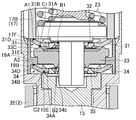
- the sectional view of a boosting mechanism when the valve concerning a 1st embodiment is in a closed state is shown.
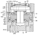
- the sectional view of the boosting mechanism when the valve according to the first embodiment is in the open state is shown.
- (A) is a top view of the boosting mechanism and the moving part in the valve closed state in the second embodiment, and (b) is a cross-sectional view along the line XI-XI of (a).
- (A) is a top view of the boosting mechanism and the moving part in the state where the valve is open in the second embodiment,
- (b) is a cross-sectional view along the line XII-XII of (a).
- the schematic of a semiconductor manufacturing apparatus is shown.
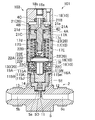
- FIG. 1 shows a longitudinal sectional view of the valve 1 in the closed state in the first embodiment.
- the valve 1 is a diaphragm valve and is used in a gas line (for example, the most upstream side of the gas line) configured by a plurality of fluid control devices of the fluid control device 55 (FIG. 13) It is a valve.
- the valve 1 includes a body 2 and an actuator 3.
- the actuator 3 of the valve 1 will be described as the upper side and the body 2 side as the lower side.
- the body portion 2 has a body 5 and a diaphragm 11.
- a cylindrical valve chamber 5a and an inflow passage 5b and an outflow passage 5c communicating with the valve chamber 5a are formed.
- An annular valve seat 5D protruding toward the casing 10 is provided on the periphery (the opening of the inflow path 5b) of the portion where the inflow path 5b of the body 5 and the valve chamber 5a communicate with each other.
- the valve seat 5D is made of the same metal material as the body 5.
- the body 5 is provided so as to extend upward, has a cylindrical shape, and has a cylindrical portion 5E having an internal thread portion formed on the inner peripheral portion.
- the diaphragm 11 is constituted by a plurality of diaphragms, and the outer peripheral edge portion of the diaphragm 11 is narrowed by the annular pressing adapter 12 and held against the body 5.
- the diaphragm 11 which is a valve body has a substantially spherical shell shape, and a substantially arc shape convex upward is in a natural state.
- the diaphragm 11 abuts and separates from the valve seat 5D, communication or blocking between the inflow passage 5b and the outflow passage 5c is performed.
- the valve 1 is in the closed state, the diaphragm 11 abuts on the valve seat 5D, and the inflow passage 5b and the outflow passage 5c are shut off.
- the diaphragm 11 is separated from the valve seat 5D, and the inflow passage 5b and the outflow passage 5c communicate with each other.
- the actuator 3 has a casing 10, a pressure adapter 12, a diaphragm pressure member 13, a rod 14, a moving member 15, a drive unit 20, and first to fourth O-rings 4A to 4D.
- the casing 10 comprises a bonnet 16, an intermediate casing 17, an actuator cap 18 and a support ring 19.
- the bonnet 16 has a substantially cylindrical shape, and is fixed to the body 5 by screwing the male screw portion on the outer periphery of the lower end portion thereof with the cylindrical portion 5E of the body 5.
- a female screw portion is formed on the inner circumference of the upper end portion of the bonnet 16.
- the intermediate casing 17 is substantially cylindrical and has an upper portion 17A and a lower portion 17B.
- a through hole 17c is formed in the upper side portion 17A, and an accommodation hole 17d having a larger inside diameter than the through hole 17c is formed in the lower side portion 17B.
- An outwardly projecting protrusion 17E is provided on the outer periphery of the lower side 17B.
- Male screw parts are formed on the outer peripheral surface of the lower side part 17B and above and below the projecting part 17E.
- the intermediate casing 17 is fixed to the bonnet 16 by screwing the lower male screw portion of the protruding portion 17E to the female screw portion at the upper end of the bonnet 16.
- the lower end of the lower side portion 17B has an annular lower surface 17F, and the inner diameter side of the lower surface 17F is configured to be positioned inside the inner peripheral surface of the support ring 19 described later.
- a first O-ring 4A is provided on the outer periphery of the upper portion 17A to prevent the drive fluid from leaking from a fluid introduction chamber 21d described later.
- the actuator cap 18 has a substantially cylindrical shape, and is fixed to the intermediate casing 17 by screwing an internal thread provided on the inner periphery of the lower end portion thereof with an external thread on the upper side of the projecting portion 17E of the intermediate casing 17. ing.
- the actuator cap 18 is formed with a fluid inflow path 18a into which the driving fluid flows, and an upper end portion of the fluid inflow path 18a is formed with a threaded portion 18b for screwing a pipe joint (not shown). .
- the support ring 19 has a cylindrical shape, and is disposed on the step portion 16A provided on the inner periphery of the bonnet 16.
- the upper end of the support ring 19 abuts on the lower surface 17 F of the intermediate casing 17, and the lower end of the support ring 19 abuts on a stepped portion 16 A provided on the inner periphery of the bonnet 16.
- the support ring 19 can not move up and down with respect to the bonnet 16.
- an inward projecting portion 19A is provided on the inner circumference of the support ring 19.
- the diaphragm presser 13 is provided on the upper side of the diaphragm 11, supported movably in the vertical direction by the presser adapter 12, and can press the central portion of the diaphragm 11.
- the rod 14 is provided on the upper side of the diaphragm presser 13, supported movably in the vertical direction by the presser adapter 12, and capable of pressing the diaphragm presser 13.
- the moving member 15 is vertically movably supported at the lower end portion of the bonnet 16.
- the moving member 15 has a cylindrical portion 15A and a flange portion 15B.
- the cylindrical portion 15A can press the rod 14.
- the flange portion 15B is provided on the upper side portion of the cylindrical portion 15A so as to protrude outward.
- a recess 15d is formed in the central portion of the upper surface 15C of the flange portion 15B.
- An annular first protrusion 15E is provided on the outer peripheral edge of the flange 15B so as to protrude upward.
- the drive unit 20 is configured of a piston 21, a spring support member 22, two coil springs 23, and a power boosting mechanism 30.
- the drive unit 20 is an air pressure drive type drive unit.
- the piston 21 and the two coil springs 23 correspond to driving means, and the spring receiving member 22 corresponds to a reciprocating member.
- the piston 21 has a substantially disc-shaped base 21A, a first upper extension 21B extending upward from the center of the base 21A, and a first lower extension 21C extending downward from the center of the base 21A. Equipped with
- the base 21 ⁇ / b> A is located above the upper portion 17 ⁇ / b> A of the intermediate casing 17 in the actuator cap 18.
- a second O-ring 4B is provided on the outer peripheral edge of the base 21A.
- the second O-ring 4B suppresses the radial movement of the base 21A when the base 21A moves in the vertical direction.
- the lower surface of the base 21A and the upper surface of the upper portion 17A of the intermediate casing 17 form a fluid introduction chamber 21d.
- the second O-ring 4B prevents the drive fluid from leaking from the fluid introduction chamber 21d.
- the upper portion of the first upward extending portion 21B is inserted into the fluid inflow path 18a.
- the third O-ring 4C suppresses the radial movement of the first upper extending portion 21B when the first upper extending portion 21B moves in the vertical direction. In addition, the third O-ring 4C prevents the drive fluid from leaking to the outside.
- the piston 21 is formed with a fluid introduction passage 21e which extends from the upper end of the first upward extension 21B to the lower surface of the base 21A and communicates with the fluid introduction chamber 21d.
- the first lower extending portion 21C penetrates the through hole 17c, and the radial direction of the first lower extending portion 21C when the first lower extending portion 21C moves up and down by the fourth O-ring 4D. Movement is suppressed.
- the fourth O-ring 4D prevents the drive fluid from leaking from the fluid introduction chamber 21d.
- a male screw portion is formed on the outer periphery of the lower end portion of the first lower extending portion 21C.
- the spring receiving member 22 is located below the piston 21 and includes a spring receiving portion 22A, a second upper extending portion 22B, and a second lower extending portion 22C.
- the spring receiving member 22 is provided so as to be capable of reciprocating in the vertical direction in the casing 10 together with the piston 21.
- the spring receiving portion 22A includes a disc-shaped main body portion 22D, a disc-shaped upper projecting portion 22E projecting upward from the upper surface of the main body portion 22D, and a disc-like projecting downward from the lower surface of the main body portion 22D. And a lower protrusion 22F.
- the main body 22D is located inside the intermediate casing 17, and the diameter of the main body 22D is smaller than the inner diameter of the accommodation hole 17d of the intermediate casing 17.
- the second upper extension 22B has a cylindrical shape with a bottom, and is provided to extend upward from the central portion of the upper protrusion 22E.
- a female screw is formed on the inner peripheral surface of the second upper extension 22B, and is screwed into the male screw of the first lower extension 21C.
- the second lower extending portion 22C has a regular hexagonal column shape, and is provided to extend downward from the central portion of the lower protruding portion 22F.
- the lower end of the second lower extending portion 22C is configured to be located in the recess 15d of the moving member 15.
- the two coil springs 23 are disposed in the accommodation hole 17d of the intermediate casing 17 between the lower surface of the upper portion 17A and the upper surfaces of the main portion 22D of the spring receiving portion 22A and the upper protrusion 22E.
- the two coil springs 23 always bias the spring receiving member 22 downward, whereby the piston 21 is always biased downward.
- FIG. 2 shows a cross-sectional perspective view around the boosting mechanism 30.
- FIG. 3 (a) shows a perspective view of a state in which the first lever 31 (second lever 34) and the first retainer 32 (second retainer 35) are combined
- FIG. 3 (b) shows the first retainer 32.
- the perspective view of (2nd retainer 35) is shown.
- the boosting mechanism 30 includes six first levers 31, a first retainer 32, a transmission member 33, six second levers 34, and a second retainer 35.
- the six first levers 31 correspond to a first lever portion
- the six second levers 34 correspond to a second lever portion.
- the six first levers 31 independently have the same shape, and are arranged at equal intervals along the circumferential direction of the actuator 3 around the second lower extension 22C.
- Each first lever 31 is made of metal (for example, stainless steel), resin, ceramic or the like, and has a hardness that does not deform (do not distort) when the valve 1 is opened or closed. That is, each first lever 31 functions as a rigid body with respect to the opening / closing operation of the valve 1.
- Each first lever 31 has an inner portion 31A and an outer portion 31B, and is tapered from the outer portion 31B toward the inner portion 31A.
- the outer side portion 31B is connected to the inner side portion 31A so as to be bent upward.
- An engagement hole 31c is formed in the inner portion 31A.
- each first lever 31 is in contact with the lower surface 17F of the intermediate casing 17, and the inner end 31E is opposed to the respective surfaces of the regular hexagonal column of the second lower extension 22C so that the lower projection is formed. It is arrange
- the first retainer 32 is made of a flexible material such as rubber, has a substantially hexagonal shape in a plan view, and is formed with a regular hexagonal insertion hole 32a.
- the first retainer 32 has an annular portion 32B, six engagement protrusions 32C, and six support protrusions 32D.
- Each of the six engagement protrusions 32C has a substantially cylindrical shape, and is disposed at equal intervals in the circumferential direction of the actuator 3 with respect to the annular portion 32B.
- the six support protrusions 32D are provided between the adjacent engagement protrusions 32C, and have a shape that tapers toward the center of the annular portion 32B in a plan view.
- Each first lever 31 is held by the first retainer 32 by inserting the engagement protrusion 32C of the first retainer 32 into the engagement hole 31c of the inner portion 31A.
- the rotation of each first lever 31 is suppressed by arranging each first lever 31 between the adjacent support protrusions 32D.
- a second lower extension 22C of a regular hexagonal column shape is inserted into the regular hexagonal insertion hole 32a of the annular portion 32B. Since the insertion hole 32a has a dimension slightly larger than the outer diameter of the second lower extension 22C, the rotation of the first retainer 32 with respect to the second lower extension 22C is suppressed.
- the transmission member 33 is located below the first lever 31 and the first retainer 32, has an annular shape, and is formed with a regular hexagonal insertion hole 33a.
- annular second protrusion 33C is provided which protrudes upward.
- the second projection 33C is in contact with the outer side portion 31B of each first lever 31 from the lower side inside the outer end portion 31D.
- annular third protrusion 33E is provided which protrudes downward. The third protrusion 33E is located more inward than the second protrusion 33C.
- the third projection 33E is located on the same side as the inner end 31E side of the outer side 31B of the first lever 31 with respect to the second projection 33C.
- a recess 33f is formed on the upper surface 33B of the transmission member 33 and inside the second protrusion 33C.
- the second lower extension 22 ⁇ / b> C of the regular hexagonal column is inserted into the regular hexagonal insertion hole 33 a of the transmission member 33. Since the insertion hole 33a has a dimension slightly larger than the outer diameter of the second lower extending portion 22C, the rotation of the transmission member 33 with respect to the second lower extending portion 22C is suppressed.
- the six second levers 34 and the second retainers 35 are located below the transmission member 33, and have the same configuration and shape as the six first levers 31 and the first retainers 32, respectively.
- each second lever 34 is made of metal (for example, stainless steel), resin, ceramics, etc., and has a hardness that does not deform (do not distort) at the time of opening and closing operation of the valve 1 described later. It has the formed inside part 34A and the outside part 34B.
- the outer end 34D of each second lever 34 abuts on the lower surface 19B of the protrusion 19A of the support ring 19, and the inner end 34E faces each surface of the regular hexagonal column of the second lower extension 22C. And the third projection 33E.
- the second retainer 35 In the second retainer 35, a regular hexagonal insertion hole 35a is formed.
- the second retainer 35 has an annular portion 35B, six engagement protrusions 35C, and six support protrusions 35D.
- Each second lever 34 is held by the second retainer 35 by inserting the engagement projection 35C of the second retainer 35 into the engagement hole 34c of the inner portion 34A.
- the rotation of each second lever 34 is suppressed by arranging each second lever 34 between the adjacent support protrusions 35D.
- a second lower extension 22C of a regular hexagonal column shape is inserted into the regular hexagonal insertion hole 35a of the annular portion 35B. Since the insertion hole 35a has a dimension slightly larger than the outer diameter of the second lower extension 22C, the rotation of the second retainer 35 relative to the second lower extension 22C is suppressed.
- each second lever 34 As the transmission member 33 moves downward, the inner end 34E of each second lever 34 is pushed by the third projection 33E of the transmission member 33 and abuts against the lower surface 19B of the projection 19A of the support ring 19 It pivots around the end 34D. As a result, the first projection 15E of the moving member 15 that abuts the second lever 34 from below is pushed downward, and the moving member 15 moves downward.
- the moving member 15 presses the rod 14 downward, and the rod 14 presses the diaphragm retainer 13 downward, whereby the diaphragm 11 is pressed to abut the valve seat 5D, and the communication between the inflow passage 5b and the outflow passage 5c. Is cut off.
- the force (driving force) by which the two coil springs 23 push the spring receiving portion 22A of the spring receiving member 22 is amplified by the power boosting mechanism 30 to press the moving member 15. ing. That is, the contact point A1 of the outer end 31D of the first lever 31 with respect to the lower surface 17F of the intermediate casing 17 is a fulcrum, and the contact point B1 of the lower projection 22F of the inner end 31E of the first lever 31 with the lower surface 22G is a force point With the contact portion C1 of the transmission member 33 of the outer side portion 31B of the first lever 31 against the second projection 33C as an action point, the force is amplified by the principle of leverage and transmitted to the transmission member 33.
- the inner end 31E of the first lever 31 is the force application point
- the outer end 31D is the fulcrum
- the portion of the outer part 31B of the first lever 31 that contacts the second projection 33C is the action point Equivalent to.
- the second protrusion 33C corresponds to a force receiving portion.
- the contact portion A2 of the outer end 34D of the second lever 34 with the lower surface 19B of the support 19 of the support ring 19 is a fulcrum
- the third projection 33E of the transmission member 33 of the inner end 34E of the second lever 34 is The force is amplified by the principle of leverage with the contact portion B2 as the force point and the contact portion C2 of the inner portion 34A of the second lever 34 against the first projection 15E of the moving member 15 as the action point, and transmitted to the moving member 15 Be done.
- the inner end 34E of the second lever 34 corresponds to a force application point
- the outer end 34D corresponds to a fulcrum
- the part in contact with the first projection 15E of the inner part 34A of the second lever 34 corresponds to an action point.
- the third protrusion 33E corresponds to a transmission unit.
- the biasing force of the two coil springs 23 is amplified by the power boosting mechanism 30 so as to press the moving member 15.
- the diaphragm 11 is pressed against the pressure of the fluid flowing in the inflow path 5b to interrupt the communication between the inflow path 5b and the outflow path 5c. be able to.
- the diaphragm presser 13 and the rod 14 are pushed up by the diaphragm 11 being pushed up, and the moving member 15 is also pushed up.
- the second lever 34 is pushed upward by the first projection 15E of the moving member 15, and the second lever 34 pivots about its outer end 34D, The inner end 34E is pushed up.
- the third projection 33E of the transmission member 33 is pushed upward by the inner end 34E of the second lever 34, and the first lever 31 is pushed upward by the second projection 33C of the transmission member 33.
- the first lever 31 is pivoted about its outer end 31D to push up the inner end 31E.
- the air pressure required to open the valve may be slightly larger than the biasing force of the two coil springs 23, and the biasing force of the two coil springs 23 can be reduced by the boosting mechanism 30. As such, the air pressure required to open the valve may be small.
- the boosting mechanism 30 does not deform the plurality of first levers when the biasing force (driving force) of the two coil springs 23 is amplified.
- Each first lever 31 is in contact with a power point portion (inner end portion 31E) receiving a force from the spring receiving portion 22A of the spring receiving member 22 and the lower surface 17F of the intermediate casing 17. It has a fulcrum portion (outer end 31D) which is the center of rotation, and an action point (a portion in contact with the second projection 33C of the outer portion 31B) for transmitting a force to the moving member 15.
- each first lever 31 is not deformed when the valve 1 is opened and closed. That is, each first lever 31 does not deform even under repeated stress, and does not deform an elastic-plastic region which is plastically deformed at a micro level which causes fatigue failure. Therefore, even if the required number of opening / closing operations of the actuator 3 and the valve 1 is, for example, 10 million times or more, it is possible to provide the actuator 3 and the valve 1 having excellent durability satisfying the requirements.
- the driving means is constituted by the piston 21 to which the spring receiving member 22 is connected, and the two coil springs 23 which bias the spring receiving member 22 toward the moving member 15.
- the biasing force (driving force) of the coil spring 23 is amplified by the plurality of first levers 31, even if the biasing force of the coil spring 23 is small, it resists the pressure of the fluid flowing through the inflow path 5b.
- the diaphragm 11 can be pressed to shut off the communication between the inflow passage 5b and the outflow passage 5c.
- the boosting mechanism 30 includes the first lever portion (six first levers 31), the transmission member 33, and the second lever portion (six second And a lever 34).
- the first lever 31 is located between the spring receiving portion 22A of the spring receiving member 22 and the transmission member 33, and has a force application portion (inner end 31E), a fulcrum (outer end 31D), and an action point ( And the transmission member 33 is positioned between the first lever 31 and the second lever 34, and the action point of the first lever 31.
- a force receiving portion for receiving a force from the force receiving portion, and a transmission that transmits the force to the second lever 34 on the same side of the force receiving portion with respect to the action point portion of the first lever 31
- the second lever 34 includes a force application point (inner end 34E), a fulcrum (outer end 34D), and a first projection of the action point (inner side 34A). And a portion abutting against the portion 15E.
- the third projection 33E of the transmission member 33 is located on the same side as the inner end 31E of the outer side 31B of the first lever 31 with respect to the second projection 33C.
- the arrangement space of the lever structure consisting of a plurality of stages can be reduced.
- the actuator 3 and the valve 1 having the small-sized and high-power boosting mechanism 30 can be provided.
- the driving means is constituted by the piston 21 to which the spring receiving member 22 is connected, and the two coil springs 23 which bias the spring receiving member 22 toward the moving member 15. According to this configuration, since the biasing force of the coil spring 23 is amplified by the boosting mechanism 30, even if the biasing force of the coil spring 23 is small, the diaphragm 11 is resisted against the pressure of the fluid flowing through the inflow path 5b. By pressing, communication between the inflow passage 5b and the outflow passage 5c can be cut off.
- FIG. 6 is a longitudinal sectional view of the valve 101 in the closed state in the second embodiment.
- the valve 101 is a diaphragm valve and is used in a gas line (for example, the most upstream side of the gas line) configured by a plurality of fluid control devices of the fluid control device 55 (FIG. 13). It is a valve.
- the valve 101 includes a body 2 and an actuator 103.
- the actuator 103 of the valve 101 is described as the upper side and the body portion 2 side as the lower side.
- the actuator 103 has a casing 10, a press adapter 12, a diaphragm press 13, a rod 14, a moving unit 115, a drive unit 20, and first to fourth O-rings 4A to 4D.
- the moving unit 115 is supported at the lower end portion of the bonnet 16 so as to be movable in the vertical direction.
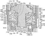
- FIG. 7 is a cross-sectional perspective view of the vicinity of the boosting mechanism 130.
- FIG. 8 is a perspective view of a state in which the boosting mechanism 130 and the moving unit 115 are combined.
- FIG. 9 is an exploded perspective view of the boosting mechanism 130 and the moving unit 115.
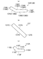
- FIG. 10 (a) is a side view of the first lever 134 (second lever 138)
- FIG. 10 (b) is a side view of the first transmission member 137
- FIG. 10 (c) is a second view. It is a side view of transmission member 115A.
- the boosting mechanism 130 has a first boosting portion 131, a first transmission portion 132, and a second boosting portion 133. As shown in FIG. 8, on the moving unit 115, the second boosting unit 133, the first transmission unit 132, and the first boosting unit 131 are stacked in this order.
- the first boosting portion 131 has six first levers 134 and a first support member 135.
- the six first levers 134 independently have the same shape, and are arranged at equal intervals along the circumferential direction of the actuator 103 around the second lower extension 22C.
- Each first lever 134 is made of metal (for example, stainless steel), resin, ceramic or the like, and has a hardness that does not deform (do not distort) when the valve 101 is opened and closed. That is, each first lever 134 functions as a rigid body for the opening and closing operation of the valve 101.
- Each first lever 134 has an inner portion 134A and an outer portion 134B, and is tapered from the outer portion 134B toward the inner portion 134A.
- the outer side portion 134B is connected to be bent upward with respect to the inner side portion 134A.
- the first lever 134 has an upper surface 134C and a lower surface 134D.
- the portions constituting the inner portion 134A and the outer portion 134B of the upper surface 134C and the lower surface 134D are each planar.
- each first lever 134 extends parallel to a tangential direction of a circle centered on the axis of the actuator 103. Then, as shown in FIG. 7, the outer end 134E of each first lever 134 makes line contact with the lower surface 17F of the intermediate casing 17, and the inner end 134F is a regular hexagonal column of the second lower extension 22C. Are in line contact with the lower surface 22G of the lower protrusion 22F.
- the first support member 135 is made of an elastic material having flexibility, such as rubber, and has a substantially hexagonal ring shape in a plan view, and an insertion hole 135a is formed.
- An inner portion 134A of each first lever 134 is bonded to a portion of each side of the substantially hexagonal shape of the first support member 135 by an adhesive or the like.
- the six first levers 134 and the first support member 135 are integrated.
- the second lower extension 22 ⁇ / b> C having a regular hexagonal column shape is inserted into the substantially hexagonal insertion hole 135 a of the first support member 135.
- the insertion hole 135a has a dimension slightly larger than the outer diameter of the second lower extending portion 22C, so that the rotation of the first boosting portion 131 with respect to the second lower extending portion 22C is suppressed.
- the first transmission portion 132 is located below the first power boosting portion 131, and has a ring member 136 and six first transmission members 137.
- the six first transmission members 137 correspond to a first transmission unit.
- the ring member 136 is made of, for example, a metal (for example, stainless steel), a resin, a ceramic, or the like, has an annular shape, and has a regular hexagonal insertion hole 136a.
- the outer circumferential surface 136B of the ring member 136 is tapered downward.
- the second lower extension 22C of the regular hexagonal column is inserted into the regular hexagonal insertion hole 136a of the ring member 136. Since the insertion hole 136a has a dimension slightly larger than the outer diameter of the second lower extension 22C, the rotation of the ring member 136 with respect to the second lower extension 22C is suppressed.
- Each first transmission member 137 is made of, for example, a plate material such as metal (for example, stainless steel), resin, ceramics, etc., and has a hardness which does not deform (do not distort) at the opening and closing operation of the valve 101. It has a shape. As shown in FIG. 10B, each first transmission member 137 has an upper surface 137A and a lower surface 137B. As shown in FIG. 9, the first transmission members 137 are arranged at equal intervals along the circumferential direction of the actuator 103 around the second lower extending portion 22 C, and the upper surface 137 A of each first transmission member 137 is The outer peripheral surface 136B of the ring member 136 is joined by an adhesive, brazing or welding. Thus, each first transmission member 137 is inclined with respect to the axial direction of the actuator 103, and the upper end portion 137C is located radially outward of the lower end portion 137D.
- a plate material such as metal (for example, stainless steel), resin, ceramics, etc.
- each first transmission member 137 extends parallel to the tangential direction of a circle centered on the axis of the actuator 103. Then, as shown in FIG. 7, the upper end portion 137C of each first transmission member 137 makes line contact with the lower surface 134D on the outer side portion 134B side of each first lever 134, and the lower end portion 137D has a second lower extension. It faces each surface of the regular hexagonal column of the protrusion 22C. Further, each first transmission member 137 is configured to be tapered from the upper end portion 137C to the lower end portion 137D. The upper end portion 137C of each first transmission member 137 corresponds to a first contact portion.
- the second boosting portion 133 is located below the first transmission portion 132, and includes six second levers 138 and a second support member 139.
- the six second levers 138 and the second support members 139 have the same configuration and shape as the six first levers 134 and the first support members 135, respectively.
- each second lever 138 is made of metal (for example, stainless steel), resin, ceramic or the like, has a hardness that does not deform (do not distort) at the time of opening / closing operation of the valve 101 described later. And an outer side 138B.
- the outer end 138E and the inner end 138F of each second lever 138 extend parallel to the tangential direction of a circle centered on the axis of the actuator 103.
- the second lever 138 has an upper surface 138C and a lower surface 138D, and portions constituting the inner portion 138A and the outer portion 138B of the upper surface 138C and the lower surface 138D are planar. There is no.
- each second lever 138 makes line contact with the lower surface 19B of the protrusion 19A of the support ring 19, and each upper surface 138C of the inner end 138F
- the lower end portion 137D of the first transmission member 137 is in line contact.
- the lower end portion 137D of each first transmission member 137 corresponds to a second contact portion.
- the second support member 139 is made of a flexible elastic material such as rubber, and has a substantially hexagonal ring shape in a plan view, and an insertion hole 139a is formed.
- An inner portion 138A of each second lever 138 is bonded to a portion of each side of the substantially hexagonal shape of the second support member 139 by an adhesive or the like. Thereby, the six second levers 138 and the second support member 139 are integrated.
- the second lower extending portion 22C having a regular hexagonal column shape is inserted into the substantially hexagonal insertion hole 139a of the second support member 139.
- the insertion hole 139a has a size slightly larger than the outer diameter of the second lower extending portion 22C, so that the rotation of the second force multiplying portion 133 with respect to the second lower extending portion 22C is suppressed.
- the moving unit 115 has six second transmission members 115A and a moving member 115B.
- the six second transmission members 115A correspond to a second transmission unit.
- the six second transmission members 115A have the same configuration and shape as the six first levers 134 except for the size thereof.
- each second transmission member 115A is made of metal (for example, stainless steel), resin, ceramic or the like, has a hardness that does not deform (do not distort) at the time of opening / closing operation of the valve 101 described later , And an outer side portion 115D.
- the outer end 115G and the inner end 115H of each second transmission member 115A extend parallel to the tangential direction of a circle centered on the axis of the actuator 103.
- the second transmission member 115A has an upper surface 115E and a lower surface 115F, and the portions constituting the inner portion 115C and the outer portion 115D of the upper surface 115E and the lower surface 115F are planar.
- each second transmission member 115A makes line contact with the lower surface 138D on the inner side 138A side of each second lever 138, and the inner end 115H is a second It opposes each surface of the regular hexagonal column of lower extending part 22C.
- the outer end 115G of each second transmission member 115A corresponds to a third contact portion.
- the moving member 115B is made of metal (for example, stainless steel), resin, ceramic or the like, and has a cylindrical base 115J and a protrusion 115K.
- the lower surface of the cylindrical base portion 115 J can press the rod 14.
- the protrusion 115K is provided on the outer peripheral edge of the upper surface of the cylindrical base 115J so as to protrude upward and radially outward.
- the protrusion 115K has an annular shape, and the protrusion 115K forms a recess 115m.
- Six second transmission members 115A are fixed to the upper surface 115N of the protrusion 115K by an adhesive, brazing, welding or the like so as to be equally spaced along the circumferential direction of the actuator 103.
- FIG. 11 (a) is a plan view of the boosting mechanism 130 and the moving part 115 when the valve 101 is in a closed state
- FIG. 11 (b) is a cross-sectional view taken along line XI-XI of FIG. 11 (a). is there.
- 12 (a) is a plan view of the boosting mechanism 130 and the moving part 115 when the valve 101 is in the open state
- FIG. 12 (b) is a cross-sectional view along the line XII-XII of FIG. 12 (a). is there.
- the first support member 135 and the second support member 139 are not shown.
- each first lever 134 is pushed by the lower surface 22G of the lower projection 22F, and each first lever 134 It pivots around an outer end portion 134E that contacts the lower surface 17F of the intermediate casing 17.
- the upper end portions 137C of the first transmission members 137 that contact the first levers 134 from below are pushed downward, and the ring member 136 and the first transmission members 137 move downward.
- each first transmission member 137 is moved downward, the inner end 138F of each second lever 138 is pushed by the lower end 137D of each first transmission member 137, and each second lever 138 It pivots around an outer end portion 138E that abuts the lower surface 19B of the protrusion 19A of the support ring 19.
- the outer end portions 115G of the second transmission members 115A that are in contact with the second lever 138 from below are pushed downward, and the moving member 115B of the moving unit 115 moves downward.
- the moving member 115B presses the rod 14 downward, and the rod 14 presses the diaphragm retainer 13 downward, whereby the diaphragm 11 is pressed and abuts on the valve seat 5D, and the communication between the inflow path 5b and the outflow path 5c Is blocked.
- the first support member 135 and the second support member 139 are made of an elastic material, the first support member 135 and the second support member are rotated by rotation of the first levers 134 and the second levers 138.
- the diameters of the outer peripheral portion and the inner peripheral portion of 139 are deformed so as to expand and contract.
- the force (driving force) by which the two coil springs 23 push the spring receiving portion 22A of the spring receiving member 22 is boosted by the power boosting mechanism 130 to press the moving portion 115. It is done. That is, the contact point A3 of the outer end 134E of the first lever 134 with the lower surface 17F of the intermediate casing 17 is a fulcrum, and the contact point B3 of the lower projection 22F of the inner end 134F of the first lever 134 with the lower surface 22G is a force point The force is multiplied by the principle of leverage and transmitted to the first transmission member 137, with the contact portion C3 of the outer portion 134B of the first lever 134 against the upper end 137C of the first transmission member 137 acting as an action point.
- the inner end 134F of the first lever 134 is the point of force
- the outer end 134E is the fulcrum
- the portion of the outer portion 134B of the first lever 134 that contacts the upper end 137C of the first transmission member 137 is It corresponds to the point of action.
- the abutment portion A4 of the outer end 138E of the second lever 138 against the lower surface 19B of the protrusion 19A of the support ring 19 is a fulcrum, and the inner end 138F of the second lever 138 is lower
- the force is boosted by the principle based on the principle that the contact portion B4 is a force point and the contact portion C4 of the inner portion 138A of the second lever 138 against the outer end portion 115G of the second transmission member 115A is a force point.
- the inner end 138F of the second lever 138 functions as a point of force
- the outer end 138E functions as a fulcrum
- the portion of the inner portion 138A of the second lever 138 that abuts against the outer end 115G of the second transmission member 115A functions. It corresponds to the point section.
- the biasing force of the two coil springs 23 is configured to be boosted by the boosting mechanism 130 to press the moving portion 115. Thereby, even if the biasing force of the two coil springs 23 is small, the diaphragm 11 is pressed against the pressure of the fluid flowing in the inflow path 5b to interrupt the communication between the inflow path 5b and the outflow path 5c. be able to.
- the second lever 138 is pushed upward by the outer end 115G of the second transmission member 115A, and the second lever 138 pivots about the outer end 138E.
- the inner end 138F is pushed up.
- the lower end 137D of the first transmission member 137 is pushed upward by the inner end 138F of the second lever 138, and the first lever 134 is pushed upward by the upper end 137C of the first transmission member 137.
- the first lever 137 is pivoted about its outer end 134E to push up the inner end 134F.
- the air pressure required to open the valve may be slightly larger than the biasing force of the two coil springs 23, and the biasing force of the two coil springs 23 may be reduced by the boosting mechanism 130. As such, the air pressure required to open the valve may be small.
- the first electromotive force unit 131 has the plurality of first levers 134 and the plurality of first transmission members corresponding to the first transmission unit. 137 are provided corresponding to the plurality of first levers 134.
- Each of the first levers 134 is a force point portion (inner end portion 134F) receiving a force from the spring receiving member 22 and a fulcrum portion that abuts on the lower surface 17F of the intermediate casing 17 and serves as a center of rotation of each first lever 134 (The outer end portion 134E) and an action point portion (a portion in contact with the upper end portion 137C of the first transmission member 137 of the outer side portion 134B) for transmitting the force to the first transmission member 137;
- the member 137 has a first contact portion (upper end portion 137C) in line contact with the action point portion of each first lever 134.
- each first transmission member 137 contacts the respective first levers 134 not by a point but by a line, so that the forces are concentrated at the mutually contacting portions of the respective first levers 134 and the respective first transmission members 137. Can be prevented. For this reason, even if the required number of times of opening and closing of the actuator 103 and the valve 101 is, for example, 10 million times or more, the actuator 103 and the valve 101 having excellent durability satisfying the request can be provided.
- the second booster 133 has a plurality of second levers 138 provided corresponding to the first transmission member 137, and the second transmission The plurality of second transmission members 115A corresponding to the above are provided corresponding to the plurality of second levers 138.
- Each of the second levers 138 is in contact with a power point portion (inner end portion 138F) receiving the force from the first transmission member 137 and the lower surface 19B of the projecting portion 19A of the support ring 19 to rotate the second levers 138
- a power point portion inner end portion 138F
- a fulcrum portion outer end 138E
- an action point a portion of the inner portion 138A that abuts against the outer end 115G of the second transmission member 115A
- Each first transmission member 137 has a second contact portion (lower end portion 137D) in line contact with the power application point of each second lever 138, and each second transmission member 115A It has a third contact portion (outer end portion 115G) in line contact with the action point portion.
- each first transmission member 137 contacts the second levers 138 not with a point but with a line, so that the forces are concentrated at the mutually contacting portions of the second levers 138 and the first transmission members 137. Can be prevented.
- each second transmission member 115A contacts each second lever 138 not by a point but by a line, the forces concentrate at the mutually contacting portions of each second lever 138 and each second transmission member 115A. Can be prevented. For this reason, even if the required number of times of opening and closing of the actuator 103 and the valve 101 is, for example, 10 million times or more, the actuator 103 and the valve 101 having excellent durability satisfying the request can be provided.
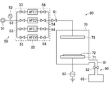
- FIG. 13 is a schematic view of a semiconductor manufacturing apparatus 60.
- the semiconductor manufacturing apparatus 60 is, for example, a CVD apparatus, has a gas supply unit 50 having a fluid control unit 55, a vacuum chamber 70, and an exhaust unit 80, and forms a passivation film (oxide film) on a wafer. Device.
- the gas supply means 50 includes a gas supply source 51, a pressure gauge 52, and a fluid control device 55.
- the fluid control device 55 has a plurality of gas lines configured of a plurality of fluid control devices, and includes on-off valves 53 and 54 and MFCs 1 to 4 (mass flow controllers) as fluid control devices.
- An open / close valve 61 is provided between the gas supply means 50 and the vacuum chamber 70.
- the vacuum chamber 70 includes a mounting table 71 for mounting the wafer 72 and an electrode 73 for forming a thin film on the wafer 72.
- a commercial power supply 62 is connected to the vacuum chamber 70.
- the exhaust means 80 includes an exhaust pipe 81, an open / close valve 82, and a dust collector 83.
- the supply of gas to the vacuum chamber 70 is controlled by opening and closing the on-off valves 53 and 54, and the MFCs 1 to 4 and the on-off valve 61. Further, when removing the particulate matter which is a by-product generated when a thin film is formed on the wafer 72, the on-off valve 82 is opened, and the particulate matter is removed by the dust collector 83 through the exhaust pipe 81. Ru.
- bulb 1, 101 in the said embodiment is applicable with respect to on-off valve 53, 54, 61, 82.
- FIG. As described above, since the valve 1 101 is excellent in durability, the fluid control device 55 excellent in durability can be provided. Further, since the valve 1, 101 includes the actuator 3, 103 having the small power boosting mechanism 30, 130, the fluid control device 55 can be miniaturized as a result.
- the etching apparatus includes a processing chamber, a gas supply unit (fluid control apparatus), and an exhaust unit, and is an apparatus for processing a material surface or the like by a corrosive action of a reactive gas.
- the sputtering apparatus comprises a target, a vacuum chamber, gas supply means (fluid control device), and exhaust means, and is an apparatus for forming a film on the surface of a material.
- the boosting mechanism 30 in the above embodiment includes the six first levers 31, the first retainer 32, the transmission member 33, the six second levers 34, and the second retainer 35. , And may be configured by only the six first levers 31 and the first retainer 32, or may be configured by only the six first levers 31. Moreover, although the boosting mechanism 30 had the six 1st levers 31, it should just be 2 or more.
- the boosting mechanism 30 includes the six first levers 31, the first retainer 32, the transmission member 33, the six second levers 34, and the second retainer 35
- the first retainer 32 And the second retainer 35 may not be provided.
- the first lever portion and the second lever portion are constituted by six members independent of each other, six first levers 31 or six second levers 34 are connected at their inner peripheral edge or outer peripheral edge It may be an integrated structure.
- the first lever 31 or the second lever 34 may be made of a material such as metal or resin that deforms as the spring receiving member 22 and the transmission member 33 move.
- the boosting mechanism 130 in the above embodiment includes the first boosting portion 131, the first transmission portion 132, and the second boosting portion 133
- the first boosting portion 131 and the first boosting portion It may be configured only by the transmission unit 132 or only by the first boosting unit 131.
- the boosting mechanism 130 includes only the first boosting portion 131 and the first transmission portion 132
- the lower end portion 137D of each first transmission member 137 is the inner portion 115C of each second transmission member 115A.
- the lower end portion 137D of each first transmission member 137 may press the projection 115K of the moving member 115B without providing the six second transmission members 115A in the moving portion 115.
- first force boosting portion 131 has six first levers 134, it may have two or more levers, and the first transmission member 137, the second lever 138, and the second transmission member 115A may The number may be the same as that of the first lever 134.
- biasing means is the two coil springs 23, it may be a disc spring.
- the two coil springs 23 are provided on the lower side of the piston 21 to bias the spring receiving member 22.
- the two coil springs 23 are provided on the upper side of the piston 21 to bias from the upper side of the piston 21 You may
- the drive means was comprised by piston 21 and the two coiled springs 23, you may be another structure.
- the actuator 3 includes the presser adapter 12, the diaphragm presser 13, and the rod 14.
- the actuator 3 may not be provided.
- the valve seat 5D is made of the same metal material as the body 5, the valve seat may be configured by embedding an annular sheet made of resin.
Landscapes
- Engineering & Computer Science (AREA)
- General Engineering & Computer Science (AREA)
- Mechanical Engineering (AREA)
- Mechanically-Actuated Valves (AREA)
- Fluid-Driven Valves (AREA)
Abstract
耐久性に優れた倍力機構を有するアクチュエータ、バルブ、および流体制御装置を提供する。 アクチュエータ(3)を備えるバルブ(1)は、倍力機構(30)は、駆動力を増幅するときに変形しない複数の第1レバー(31)を有し、各第1レバー(31)は、ばね受け部材(22)のばね受け部(22A)から力を受ける力点部(内端部(31E))と、中間ケーシング(17)の下面(17F)に当接して第1レバー(31)の回動の中心となる支点部(外端部(31D))と、移動部材(15)へ力を伝える作用点部(外側部(31B)の第2突起部(33C)に対して当接する部分)とを有する。
Description
本発明は、半導体製造装置等の流体管路に使用されるアクチュエータ、バルブ、および流体制御装置に関する。
てこの原理を利用した柔軟性のある付勢部材により力を増幅する倍力機構を備えたバルブが提案されている。(例えば、特許文献1参照)。
しかし、特許文献1に開示された倍力機構では、付勢部材に歪が発生してしまうため、耐久性が悪く、開閉回数が多いバルブでは使用することができなかった。
そこで本発明は、耐久性に優れた倍力機構を有するアクチュエータ、バルブ、および流体制御装置を提供することを目的とする。
上記目的を解決するために、本発明の一態様であるアクチュエータは、ケーシングと、前記ケーシング内に往復動可能に設けられた往復動部材と、前記ケーシング内に設けられ、前記往復動部材を駆動させる駆動手段と、前記駆動手段により前記往復動部材にかかった駆動力を増幅させる倍力機構と、前記倍力機構により増幅された力を受けて移動する移動部材と、を備え、前記倍力機構は、前記移動部材の周方向に配置され、前記駆動力を増幅するときに変形しない複数のレバーを有し、各レバーは、前記往復動部材からの力を受ける力点部と、前記ケーシングに当接して各レバーの回動の中心となる支点部と、前記移動部材へ力を伝える作用点部とを有する。
また、前記力点部は、前記各レバーの内端部であり、前記支点部は、前記各レバーの外端部であり、前記作用点部は、前記内端部と前記外端部との間に位置してもよい。
また、前記倍力機構は、前記複数のレバーを保持するリテーナを備えてもよい。
前記複数のレバーは、複数の第1レバーを有し、前記倍力機構は、前記駆動手段により前記往復動部材にかかった駆動力を倍力させる第1倍力部と、前記第1倍力部により倍力された力を伝達する第1伝達部と、を有し、前記第1倍力部は、前記往復動部材の周方向に配置された前記複数の第1レバーを有し、前記第1伝達部は、前記複数の第1レバーに対応して設けられた複数の第1伝達部材を有し、各第1レバーは、前記往復動部材からの力を受ける力点部と、前記ケーシングに当接して各第1レバーの回動の中心となる支点部と、前記第1伝達部材へ力を伝える作用点部とを有し、各第1伝達部材は、各第1レバーの作用点部に対し線接触する第1接触部を有してもよい。
前記複数のレバーは、複数の第2レバーを有し、前記倍力機構は、前記第1伝達部により伝達される力を増幅する第2倍力部と、前記第2倍力部により増幅された力を前記移動部材に伝達する第2伝達部と、をさらに備え、前記第2倍力部は、前記第1伝達部材に対応して設けられた複数の第2レバーを有し、前記第2伝達部は、前記複数の第2レバーに対応して設けられた複数の第2伝達部材を有し、各第2レバーは、前記第1伝達部からの力を受ける力点部と、前記ケーシングに当接して各第2レバーの回動の中心となる支点部と、前記第2伝達部材へ力を伝える作用点部とを有し、各第1伝達部材は、各第2レバーの力点部に対し線接触する第2接触部を有し、各第2伝達部材は、各第2レバーの作用点部に対し線接触する第3接触部を有してもよい。
また、前記駆動手段は、外部から供給される駆動流体により駆動し、前記往復動部材が接続されたピストンと、前記移動部材に向かって前記往復動部材を付勢する付勢手段と、を備えてもよい。
また、本発明の一態様であるバルブは、前記ボディに接続されるケーシングと、前記ケーシング内に往復動可能に設けられた往復動部材と、前記ケーシング内に設けられ、前記往復動部材を駆動させる駆動手段と、前記駆動手段により前記往復動部材にかかった駆動力を増幅させる倍力機構と、前記弁体により前記流体通路を開閉させるために、前記ボディに対し近接および離間移動可能に設けられ、前記倍力機構により増幅された力を受けて移動する移動部材と、を備え、前記倍力機構は、前記移動部材の周方向に配置され、前記駆動力を増幅するときに変形しない複数のレバーを有し、各レバーは、前記往復動部材からの力を受ける力点部と、前記ケーシングに当接して各レバーの回動の中心となる支点部と、前記移動部材へ力を伝える作用点部とを有する。
前記複数のレバーは、複数の第1レバーを有し、前記倍力機構は、前記駆動手段により前記往復動部材にかかった駆動力を倍力させる第1倍力部と、前記第1倍力部により倍力された力を伝達する第1伝達部と、を有し、前記第1倍力部は、前記往復動部材の周方向に配置された前記複数の第1レバーを有し、前記第1伝達部は、前記複数の第1レバーに対応して設けられた複数の第1伝達部材を有し、各第1レバーは、前記往復動部材からの力を受ける力点部と、前記ケーシングに当接して各第1レバーの回動の中心となる支点部と、前記第1伝達部材へ力を伝える作用点部とを有し、各第1伝達部材は、各第1レバーの作用点部に対し線接触する第1接触部を有してもよい。
前記複数のレバーは、複数の第2レバーを有し、前記倍力機構は、前記第1伝達部により伝達される力を増幅する第2倍力部と、前記第2倍力部により増幅された力を前記移動部材に伝達する第2伝達部と、をさらに備え、前記第2倍力部は、前記第1伝達部材に対応して設けられた複数の第2レバーを有し、前記第2伝達部は、前記複数の第2レバーに対応して設けられた複数の第2伝達部材を有し、各第2レバーは、前記第1伝達部からの力を受ける力点部と、前記ケーシングに当接して各第2レバーの回動の中心となる支点部と、前記第2伝達部材へ力を伝える作用点部とを有し、各第1伝達部材は、各第2レバーの力点部に対し線接触する第2接触部を有し、各第2伝達部材は、各第2レバーの作用点部に対し線接触する第3接触部を有してもよい。
また、本発明の一態様である流体制御装置は、前複数の流体制御機器により構成される流体制御装置であって、前記複数の流体制御機器の少なくとも一つは、上記のバルブである。
本発明によれば、耐久性に優れた倍力機構を有するアクチュエータ、バルブ、および流体制御装置を提供することができる。
本発明の一実施形態によるアクチュエータ、バルブ、および流体制御装置について、図面を参照して説明する。
第1の実施形態に係るアクチュエータおよびバルブについて説明する。
図1は、第1の実施形態における閉状態にあるバルブ1の縦断面図を示している。図1に示すように、バルブ1は、ダイヤフラムバルブであり、流体制御装置55(図13)の複数の流体制御機器により構成されるガスライン(例えば、ガスラインの最も上流側)で使用されるバルブである。
図1は、第1の実施形態における閉状態にあるバルブ1の縦断面図を示している。図1に示すように、バルブ1は、ダイヤフラムバルブであり、流体制御装置55(図13)の複数の流体制御機器により構成されるガスライン(例えば、ガスラインの最も上流側)で使用されるバルブである。
バルブ1は、ボディ部2と、アクチュエータ3とを備える。なお、以下の説明において、バルブ1の、アクチュエータ3を上側、ボディ部2側を下側として説明する。
ボディ部2は、ボディ5と、ダイヤフラム11とを有する。
ボディ5には、円柱状の弁室5aと、弁室5aに連通する流入路5bおよび流出路5cとが形成されている。ボディ5の流入路5bと弁室5aとが連通する箇所の周縁(流入路5bの開口部)には、ケーシング10に向かって突出する円環状の弁座5Dが設けられている。弁座5Dは、ボディ5と同じ金属材料により構成される。また、ボディ5は、上方に延びるように設けられ、円筒状をなし、内周部に雌ねじ部が形成された円筒部5Eを有する。
ダイヤフラム11は、複数枚のダイヤフラムにより構成され、環状の押さえアダプタ12により、その外周縁部が狭圧され、ボディ5に対し保持されている。弁体であるダイヤフラム11は、略球殻状をなし、上に凸の略円弧状が自然状態となっている。ダイヤフラム11が弁座5Dに対し当接および離間することによって、流入路5bと流出路5cとの間の連通または遮断が行われる。バルブ1が閉状態にあるときには、ダイヤフラム11が弁座5Dに当接し、流入路5bと流出路5cとが遮断される。バルブ1が開状態にあるときには、ダイヤフラム11が弁座5Dから離間し、流入路5bと流出路5cとが連通する。
アクチュエータ3は、ケーシング10と、押さえアダプタ12と、ダイヤフラム押さえ13と、ロッド14と、移動部材15と、駆動部20と、第1~第4Oリング4A~4Dとを有する。
ケーシング10は、ボンネット16と、中間ケーシング17と、アクチュエータキャップ18と、支持リング19とを備える。
ボンネット16は、略円筒状をなし、その下端部の外周の雄ねじ部がボディ5の円筒部5Eに対し螺合されることにより、ボディ5に対し固定されている。ボンネット16の上端部の内周には、雌ねじ部が形成されている。
中間ケーシング17は、略円筒状をなし、上側部17Aと、下側部17Bとを有する。上側部17Aには、貫通孔17cが形成され、下側部17Bには、貫通孔17cよりも内径が大きい収容孔17dが形成されている。下側部17Bの外周には、外方へ突出する突出部17Eが設けられている。下側部17Bの外周面であって突出部17Eの上下には、それぞれ雄ねじ部が形成されている。突出部17Eの下側の雄ねじ部が、ボンネット16の上端部の雌ねじ部に螺合することにより、中間ケーシング17がボンネット16に対し固定されている。下側部17Bの下端は、環状の下面17Fを有し、下面17Fの内径側は、後述の支持リング19の内周面よりも内側に位置するように構成されている。上側部17Aの外周には、駆動流体が後述の流体導入室21dから漏れるのを防止する第1Oリング4Aが設けられている。
アクチュエータキャップ18は、略円筒状をなし、その下端部の内周に設けられた雌ねじ部を中間ケーシング17の突出部17Eの上側の雄ねじ部に螺合させることにより、中間ケーシング17に対し固定されている。アクチュエータキャップ18には、駆動流体が流入する流体流入路18aが形成され、流体流入路18aの上端部には、図示せぬ管継手を螺合するための被螺合部18bが形成されている。
支持リング19は、円筒状をなし、ボンネット16の内周に設けられた段差部16A上に配置されている。支持リング19の上端は、中間ケーシング17の下面17Fに当接し、支持リング19の下端は、ボンネット16の内周に設けられた段差部16Aに当接している。これにより、支持リング19は、ボンネット16に対し上下動不能である。また、支持リング19の内周には、内方に突出する突出部19Aが設けられている。
ダイヤフラム押さえ13は、ダイヤフラム11の上側に設けられ、押さえアダプタ12により上下方向に移動可能に支持され、ダイヤフラム11の中央部を押圧可能である。
ロッド14は、ダイヤフラム押さえ13の上側に設けられ、押さえアダプタ12により上下方向に移動可能に支持され、ダイヤフラム押さえ13を押圧可能である。
移動部材15は、ボンネット16の下端部において、上下方向に移動可能に支持されている。移動部材15は、円柱部15Aとフランジ部15Bとを有する。円柱部15Aは、ロッド14を押圧可能である。フランジ部15Bは、円柱部15Aの上側部に外方に突出するように設けられている。フランジ部15Bの上面15Cの中央部には、凹部15dが形成されている。フランジ部15Bの外周縁には、上方に突出する環状の第1突起部15Eが設けられている。
駆動部20は、ピストン21と、ばね受け部材22と、2本のコイルばね23と、倍力機構30とにより構成される。駆動部20は、空圧駆動式の駆動部である。なお、ピストン21と2本のコイルばね23とは駆動手段に相当し、ばね受け部材22は往復動部材に相当する
ピストン21は、略円板状をなす基部21Aと、基部21Aの中央部から上側に延びる第1上延出部21Bと、基部21Aの中央部から下側に延びる第1下延出部21Cとを備える。
基部21Aは、アクチュエータキャップ18内において、中間ケーシング17の上側部17Aの上側に位置している。基部21Aの外周縁には、第2Oリング4Bが設けられている。第2Oリング4Bにより、基部21Aの上下方向への移動時における基部21Aの径方向の移動が抑制される。基部21Aの下面と中間ケーシング17の上側部17Aの上面とにより、流体導入室21dが形成される。第2Oリング4Bは、駆動流体が流体導入室21dから漏れるのを防止する。
第1上延出部21Bの上側部は、流体流入路18a内に挿入されている。第3Oリング4Cにより、第1上延出部21Bの上下方向への移動時における第1上延出部21Bの径方向の移動が抑制される。また、第3Oリング4Cは、駆動流体が外部に漏れるのを防止する。ピストン21には、第1上延出部21Bの上端から基部21Aの下面に延び、流体導入室21dに連通する流体導入路21eが形成されている。
第1下延出部21Cは、貫通孔17cを貫通しており、第4Oリング4Dにより、第1下延出部21Cの上下方向への移動時における第1下延出部21Cの径方向の移動が抑制される。第4Oリング4Dは、駆動流体が流体導入室21dから漏れるのを防止する。第1下延出部21Cの下端部の外周には雄ねじ部が形成されている。
ばね受け部材22は、ピストン21の下側に位置し、ばね受け部22Aと、第2上延出部22Bと、第2下延出部22Cとを備える。ばね受け部材22は、ピストン21と共にケーシング10内を上下方向に往復動可能に設けられている。
ばね受け部22Aは、円板状の本体部22Dと、本体部22Dの上面から上側に突出する円板状の上突出部22Eと、本体部22Dの下面から下側に突出する円板状の下突出部22Fとを有する。本体部22Dは、中間ケーシング17内に位置し、本体部22Dの直径は、中間ケーシング17の収容孔17dの内径よりも小さく構成されている。
第2上延出部22Bは、有底円筒状をなし、上突出部22Eの中央部から上側に延びるように設けられている。第2上延出部22Bの内周面には雌ねじ部が形成され、第1下延出部21Cの雄ねじ部に螺合されている。これにより、ピストン21と、ばね受け部材22とは一体的に構成される。
第2下延出部22Cは、正六角柱状をなし、下突出部22Fの中央部から下側に延びるように設けられている。第2下延出部22Cの下端は、移動部材15の凹部15d内に位置するように構成されている。
2本のコイルばね23は、中間ケーシング17の収容孔17d内において、上側部17Aの下面と、ばね受け部22Aの本体部22Dおよび上突出部22Eの上面との間に配置されている。2本のコイルばね23は、ばね受け部材22を常に下側に付勢し、これにより、ピストン21も常に下側に付勢されている。
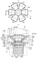
図2は、倍力機構30付近の断面斜視図を示す。図3(a)は、第1レバー31(第2レバー34)と第1リテーナ32(第2リテーナ35)とを組み合わせた状態の斜視図を示し、図3(b)は、第1リテーナ32(第2リテーナ35)の斜視図を示す。
倍力機構30は、6つの第1レバー31と、第1リテーナ32と、伝達部材33と、6つの第2レバー34と、第2リテーナ35とを備える。6つの第1レバー31は、第1レバー部に相当し、6つの第2レバー34は、第2レバー部に相当する。
6つの第1レバー31は、それぞれ独立して同形状をなし、第2下延出部22Cの周囲にアクチュエータ3の円周方向に沿って等間隔に配置されている。各第1レバー31は、金属(例えば、ステンレス鋼)、樹脂、セラミックス等により構成され、後述のバルブ1の開閉動作時に変形しない(歪まない)硬さを有している。すなわち、各第1レバー31は、バルブ1の開閉動作に対し剛体として機能する。各第1レバー31は、内側部31Aと、外側部31Bとを有し、外側部31Bから内側部31Aに向かって先細る形状をなしている。外側部31Bは、内側部31Aに対し、上側に屈曲するように接続されている。内側部31Aには、係合孔31cが形成されている。
各第1レバー31は、その外端部31Dが、中間ケーシング17の下面17Fに当接し、内端部31Eが、第2下延出部22Cの正六角柱の各面に対向して下突出部22Fの下面22Gに当接するように配置される。
第1リテーナ32は、ゴム等の柔軟性を有する材料により構成され、平面視で略六角形状をなし、正六角形状の挿入孔32aが形成されている。第1リテーナ32は、環状部32Bと、6つの係合突起32Cと、6つの支持突起32Dとを有する。
6つの係合突起32Cは、それぞれ略円柱状をなし、環状部32Bに対しアクチュエータ3の円周方向に等間隔に配置されている。
6つの支持突起32Dは、それぞれ隣り合う係合突起32Cの間に設けられており、平面視で環状部32Bの中心に向かって先細る形状をなしている。
各第1レバー31は、その内側部31Aの係合孔31cに、第1リテーナ32の係合突起32Cを挿入することにより、第1リテーナ32に保持される。各第1レバー31は、隣り合う支持突起32Dの間に配置されることにより、各第1レバー31の回転が抑制される。
環状部32Bの正六角形状の挿入孔32aに、正六角柱状の第2下延出部22Cが挿入される。挿入孔32aは、第2下延出部22Cの外形よりもわずかに大きい寸法を有するので、第1リテーナ32の第2下延出部22Cに対する回転が抑制される。
伝達部材33は、第1レバー31および第1リテーナ32の下側に位置し、環状をなし、正六角形状の挿入孔33aが形成されている。伝達部材33の上面33Bの外周縁には、上方に突出する環状の第2突起部33Cが設けられている。第2突起部33Cは、各第1レバー31の外側部31Bに対し、外端部31Dよりも内側において下側から当接している。伝達部材33の下面33Dの内周縁には、下方に突出する環状の第3突起部33Eが設けられている。第3突起部33Eは、第2突起部33Cよりも内方に位置する。つまり、第3突起部33Eは、第2突起部33Cに対して、第1レバー31の外側部31Bに対する内端部31E側と同じ側に位置する。伝達部材33の上面33Bであって、第2突起部33Cよりも内側には、凹部33fが形成されている。
伝達部材33の正六角形状の挿入孔33aに、正六角柱状の第2下延出部22Cが挿入される。挿入孔33aは、第2下延出部22Cの外形よりもわずかに大きい寸法を有するので、伝達部材33の第2下延出部22Cに対する回転が抑制される。
6つの第2レバー34および第2リテーナ35は、伝達部材33の下側に位置し、それぞれ6つの第1レバー31および第1リテーナ32と同様の構成・形状を有する。
すなわち、各第2レバー34は、金属(例えば、ステンレス鋼)、樹脂、セラミックス等により構成され、後述のバルブ1の開閉動作時に変形しない(歪まない)硬さを有し、係合孔34cが形成された内側部34Aと、外側部34Bとを有する。各第2レバー34は、その外端部34Dが、支持リング19の突出部19Aの下面19Bに当接し、内端部34Eが、第2下延出部22Cの正六角柱の各面に対向して第3突起部33Eに当接するように配置される。
第2リテーナ35には、正六角形状の挿入孔35aが形成されている。第2リテーナ35は、環状部35Bと、6つの係合突起35Cと、6つの支持突起35Dとを有する。
各第2レバー34は、その内側部34Aの係合孔34cに、第2リテーナ35の係合突起35Cを挿入することにより、第2リテーナ35に保持される。各第2レバー34は、隣り合う支持突起35Dの間に配置されることにより、各第2レバー34の回転が抑制される。
環状部35Bの正六角形状の挿入孔35aに、正六角柱状の第2下延出部22Cが挿入される。挿入孔35aは、第2下延出部22Cの外形よりもわずかに大きい寸法を有するので、第2リテーナ35の第2下延出部22Cに対する回転が抑制される。
図1に示すように、バルブ1が閉状態にある場合には、流体導入室21dに駆動流体は流入しておらず、ばね受け部材22は、2本のコイルばね23により下方に付勢されて、最下端に位置している。バルブ1が図5に示す開状態から図4に示す閉状態になるときには、各第1レバー31の内端部31Eが下突出部22Fの下面22Gに押されて、中間ケーシング17の下面17Fに当接する外端部31Dを中心に回動する。これにより、第1レバー31に下方から当接する伝達部材33の第2突起部33Cが下方に押されて、伝達部材33が下方に移動する。
伝達部材33が下方に移動することにより、各第2レバー34の内端部34Eが伝達部材33の第3突起部33Eに押されて、支持リング19の突出部19Aの下面19Bに当接し外端部34Dを中心に回動する。これにより、第2レバー34に下方から当接する移動部材15の第1突起部15Eが下方に押されて、移動部材15が下方に移動する。
移動部材15がロッド14を下方に押圧し、ロッド14がダイヤフラム押さえ13を下方に押圧することにより、ダイヤフラム11が押圧されて、弁座5Dに当接し、流入路5bと流出路5cとの連通が遮断される。
本実施形態では、2本のコイルばね23が、ばね受け部材22のばね受け部22Aを押す力(駆動力)は、倍力機構30により増幅されて、移動部材15を押圧するように構成されている。すなわち、第1レバー31の外端部31Dの中間ケーシング17の下面17Fに対する当接部A1を支点、第1レバー31の内端部31Eの下突出部22Fの下面22Gに対する当接部B1を力点、第1レバー31の外側部31Bの伝達部材33の第2突起部33Cに対する当接部C1を作用点として、てこの原理により力が増幅されて、伝達部材33に伝達される。このように、第1レバー31の内端部31Eは力点部、外端部31Dは支点部、第1レバー31の外側部31Bの第2突起部33Cに対して当接する部分は作用点部に相当する。第2突起部33Cは、力受部に相当する。
さらに、第2レバー34の外端部34Dの支持リング19の突出部19Aの下面19Bに対する当接部A2を支点、第2レバー34の内端部34Eの伝達部材33の第3突起部33Eに対する当接部B2を力点、第2レバー34の内側部34Aの移動部材15の第1突起部15Eに対する当接部C2を作用点として、てこの原理により力が増幅されて、移動部材15に伝達される。なお、第2レバー34の内端部34Eは力点部、外端部34Dは支点部、第2レバー34の内側部34Aの第1突起部15Eに対して当接する部分は作用点部に相当する。第3突起部33Eは、伝達部に相当する。
このようにして、2本のコイルばね23の付勢力は、倍力機構30により増幅されて、移動部材15を押圧するように構成される。これにより、2本のコイルばね23の付勢力が小さくても、流入路5bを流れる流体の圧力に抗して、ダイヤフラム11を押圧して、流入路5bと流出路5cとの連通を遮断することができる。
また、駆動流体を、流体流入路18aおよび流体導入路21eを介して、流体導入室21dに導入することにより、ピストン21およびばね受け部材22に対し空気圧による上向きの力が働く。この力を、2本のコイルばね23の付勢力よりも大きくすることにより、ピストン21およびばね受け部材22は上側に移動する。これにより、移動部材15を押す力がなくなるので、ダイヤフラム11が流入路5bを流れる流体の圧力およびダイヤフラム11の復元力により押し上げられ、弁座5Dから離間し、弁が開かれる。
この時、ダイヤフラム11が押し上げられることによって、ダイヤフラム押さえ13およびロッド14が押し上げられ、移動部材15も押し上げられる。これにより、図5に示すように、第2レバー34が移動部材15の第1突起部15Eにより上方に押されて、第2レバー34は、その外端部34Dを中心に回動して、内端部34Eが押し上げられる。その結果、第2レバー34の内端部34Eにより、伝達部材33の第3突起部33Eが上方に押され、伝達部材33の第2突起部33Cにより、第1レバー31が上方に押されて、第1レバー31は、その外端部31Dを中心に回動して、内端部31Eが押し上げられる。
なお、弁を開けるために必要な空気圧は、2本のコイルばね23の付勢力よりもわずかに大きければ十分であり、2本のコイルばね23の付勢力は倍力機構30により、小さくできるものであるから、弁を開けるために必要な空気圧は小さくてよい。
以上のように、本実施形態のアクチュエータ3を備えるバルブ1によれば、倍力機構30は、2本のコイルばね23の付勢力(駆動力)を増幅するときに変形しない複数の第1レバー31を有し、各第1レバー31は、ばね受け部材22のばね受け部22Aから力を受ける力点部(内端部31E)と、中間ケーシング17の下面17Fに当接して第1レバー31の回動の中心となる支点部(外端部31D)と、移動部材15へ力を伝える作用点部(外側部31Bの第2突起部33Cに対して当接する部分)とを有する。
かかる構成により、バルブ1の開閉動作時に各第1レバー31が変形しない。すなわち、各第1レバー31が、繰返し応力を受けても変形せず、疲労破壊を起こすようなミクロレベルでの塑性変形する弾塑性域も変形しない。このため、アクチュエータ3およびバルブ1の要求開閉回数が例えば1000万回以上であったとしても、当該要求を満たす耐久性に優れたアクチュエータ3およびバルブ1を提供することができる。
また、複数の第1レバー31は、第1リテーナ32により保持されるので、アクチュエータ3およびバルブ1の組立性を向上させることができる。
また、駆動手段は、ばね受け部材22が接続されたピストン21と、移動部材15に向かってばね受け部材22を付勢する2本のコイルばね23とにより構成される。かかる構成によれば、複数の第1レバー31によりコイルばね23の付勢力(駆動力)が増幅されるので、コイルばね23の付勢力が小さくても、流入路5bを流れる流体の圧力に抗して、ダイヤフラム11を押圧して、流入路5bと流出路5cとの連通が遮断することができる。
また、本実施形態のアクチュエータ3を備えるバルブ1によれば、倍力機構30は、第1レバー部(6つの第1レバー31)と、伝達部材33と、第2レバー部(6つの第2レバー34)とを備える。第1レバー31は、ばね受け部材22のばね受け部22Aと伝達部材33との間に位置し、力点部(内端部31E)と、支点部(外端部31D)と、作用点部(外側部31Bの第2突起部33Cに対して当接する部分)とを有し、伝達部材33は、第1レバー31と第2レバー34との間に位置し、第1レバー31の作用点部から力を受ける力受部(第2突起部33C)と、力受部に対して第1レバー31の作用点部に対する力点部側と同じ側に位置し、第2レバー34へ力を伝える伝達部(第3突起部33E)とを有し、第2レバー34は、力点部(内端部34E)と、支点部(外端部34D)と、作用点部(内側部34Aの第1突起部15Eに対して当接する部分)とを有する。
かかる構成によれば、伝達部材33の第3突起部33Eは、第2突起部33Cに対して、第1レバー31の外側部31Bに対する内端部31E側と同じ側に位置しているので、複数段からなるてこ構造の配置空間を小さくすることができる。よって、小型かつ高倍率な倍力機構30を有するアクチュエータ3およびバルブ1を提供することができる。
また、駆動手段は、ばね受け部材22が接続されたピストン21と、移動部材15に向かってばね受け部材22を付勢する2本のコイルばね23とにより構成される。かかる構成によれば、倍力機構30によりコイルばね23の付勢力が増幅されるので、コイルばね23の付勢力が小さくても、流入路5bを流れる流体の圧力に抗して、ダイヤフラム11を押圧して、流入路5bと流出路5cとの連通が遮断することができる。
次に、第2の実施形態に係るアクチュエータおよびバルブについて説明する。なお、第1の実施形態のアクチュエータおよびバルブと同様の構成については同じ参照番号を付し説明を省略する。
図6は、第2の実施形態における閉状態にあるバルブ101の縦断面図である。図6に示すように、バルブ101は、ダイヤフラムバルブであり、流体制御装置55(図13)の複数の流体制御機器により構成されるガスライン(例えば、ガスラインの最も上流側)で使用されるバルブである。
バルブ101は、ボディ部2と、アクチュエータ103とを備える。なお、以下の説明において、バルブ101の、アクチュエータ103を上側、ボディ部2側を下側として説明する。
アクチュエータ103は、ケーシング10と、押さえアダプタ12と、ダイヤフラム押さえ13と、ロッド14と、移動部115と、駆動部20と、第1~第4Oリング4A~4Dとを有する。
移動部115は、ボンネット16の下端部に、上下方向に移動可能に支持されている。
次に、倍力機構130および移動部115について説明する。
図7は、倍力機構130付近の断面斜視図である。図8は、倍力機構130と移動部115とを組み合わせた状態の斜視図である。図9は、倍力機構130および移動部115の分解斜視図である。図10(a)は、第1レバー134(第2レバー138)の側面図であり、図10(b)は、第1伝達部材137の側面図であり、図10(c)は、第2伝達部材115Aの側面図である。
倍力機構130は、第1倍力部131と、第1伝達部132と、第2倍力部133とを有する。図8に示すように、移動部115の上に、第2倍力部133、第1伝達部132、および第1倍力部131がこの順で積層されている。
第1倍力部131は、6つの第1レバー134と、第1支持部材135とを有する。
6つの第1レバー134は、それぞれ独立して同形状をなし、第2下延出部22Cの周囲にアクチュエータ103の円周方向に沿って等間隔に配置されている。各第1レバー134は、金属(例えば、ステンレス鋼)、樹脂、セラミックス等により構成され、後述のバルブ101の開閉動作時に変形しない(歪まない)硬さを有している。すなわち、各第1レバー134は、バルブ101の開閉動作に対し剛体として機能する。
各第1レバー134は、内側部134Aと、外側部134Bとを有し、外側部134Bから内側部134Aに向かって先細る形状をなしている。外側部134Bは、内側部134Aに対し、上側に屈曲するように接続されている。
図10(a)に示すように、第1レバー134は、上面134Cおよび下面134Dを有している。上面134Cおよび下面134Dの内側部134Aおよび外側部134Bを構成する部分は、それぞれ平面状をなしている。
各第1レバー134の外端部134Eおよび内端部134Fは、アクチュエータ103の軸を中心とする円の接線方向に平行をなすように延びている。そして、図7に示すように、各第1レバー134は、その外端部134Eが、中間ケーシング17の下面17Fに線接触し、内端部134Fが、第2下延出部22Cの正六角柱の各面に対向して下突出部22Fの下面22Gに線接触している。
第1支持部材135は、ゴム等の柔軟性を有する弾性材料により構成され、平面視で略六角環状をなし、挿入孔135aが形成されている。第1支持部材135の略六角形の各辺の部分に、各第1レバー134の内側部134Aが接着剤等により接着されている。これにより、6つの第1レバー134と第1支持部材135とが一体化されている。
第1支持部材135の略六角形状の挿入孔135aに正六角柱状の第2下延出部22Cが挿入される。挿入孔135aは、第2下延出部22Cの外形よりもわずかに大きい寸法を有するので、第1倍力部131の第2下延出部22Cに対する回転が抑制される。
第1伝達部132は、第1倍力部131の下側に位置し、リング部材136と、6つの第1伝達部材137とを有する。6つの第1伝達部材137は、第1伝達部に相当する。
リング部材136は、例えば金属(例えば、ステンレス鋼)、樹脂、セラミックス等により構成され、環状をなし、正六角形状の挿入孔136aが形成されている。リング部材136の外周面136Bは、下側に向かってテーパ状をなしている。
リング部材136の正六角形状の挿入孔136aに、正六角柱状の第2下延出部22Cが挿入される。挿入孔136aは、第2下延出部22Cの外形よりもわずかに大きい寸法を有するので、リング部材136の第2下延出部22Cに対する回転が抑制される。
各第1伝達部材137は、例えば金属(例えば、ステンレス鋼)、樹脂、セラミックス等の板材により構成され、バルブ101の開閉動作時に変形しない(歪まない)硬さを有し、それぞれ独立して同形状をなしている。図10(b)に示すように、各第1伝達部材137は、上面137Aと、下面137Bとを有する。図9に示すように、各第1伝達部材137は、第2下延出部22Cの周囲にアクチュエータ103の円周方向に沿って等間隔に配置され、各第1伝達部材137の上面137Aが、リング部材136の外周面136Bに接着剤、ロウ付けまたは溶接により接合されている。これにより、各第1伝達部材137は、アクチュエータ103の軸方向に対して傾斜し、上端部137Cが下端部137Dよりも径方向の外側に位置している。
また、各第1伝達部材137の上端部137Cおよび下端部137Dは、アクチュエータ103の軸を中心とする円の接線方向に平行をなすように延びている。そして、図7に示すように、各第1伝達部材137は、その上端部137Cは、各第1レバー134の外側部134B側の下面134Dに線接触し、下端部137Dは、第2下延出部22Cの正六角柱の各面に対向している。また、各第1伝達部材137は、上端部137Cから下端部137Dに向かうにつれて先細るように構成されている。各第1伝達部材137の上端部137Cは、第1接触部に相当する。
第2倍力部133は、第1伝達部132の下側に位置し、6つの第2レバー138と、第2支持部材139とを有する。6つの第2レバー138および第2支持部材139は、それぞれ6つの第1レバー134および第1支持部材135と同様の構成・形状を有する。
すなわち、各第2レバー138は、金属(例えば、ステンレス鋼)、樹脂、セラミックス等により構成され、後述のバルブ101の開閉動作時に変形しない(歪まない)硬さを有し、内側部138Aと、外側部138Bとを有する。各第2レバー138の外端部138Eおよび内端部138Fは、アクチュエータ103の軸を中心とする円の接線方向に平行をなすように延びている。また、図10(a)に示すように、第2レバー138は、上面138Cおよび下面138Dを有し、上面138Cおよび下面138Dの内側部138Aおよび外側部138Bを構成する部分は、それぞれ平面状をなしている。
そして、図7に示すように、各第2レバー138は、その外端部138Eが、支持リング19の突出部19Aの下面19Bと線接触し、内端部138Fの上面138Cには、各第1伝達部材137の下端部137Dが線接触している。各第1伝達部材137の下端部137Dは、第2接触部に相当する。
第2支持部材139は、ゴム等の柔軟性を有する弾性材料により構成され、平面視で略六角環状をなし、挿入孔139aが形成されている。第2支持部材139の略六角形の各辺の部分に、各第2レバー138の内側部138Aが接着剤等により接着されている。これにより、6つの第2レバー138と第2支持部材139とが一体化されている。
第2支持部材139の略六角形状の挿入孔139aに正六角柱状の第2下延出部22Cが挿入される。挿入孔139aは、第2下延出部22Cの外形よりもわずかに大きい寸法を有するので、第2倍力部133の第2下延出部22Cに対する回転が抑制される。
移動部115は、6つの第2伝達部材115Aと、移動部材115Bとを有する。6つの第2伝達部材115Aは、第2伝達部に相当する。
6つの第2伝達部材115Aは、6つの第1レバー134と寸法が小さい以外は、同様の構成・形状を有する。
すなわち、各第2伝達部材115Aは、金属(例えば、ステンレス鋼)、樹脂、セラミックス等により構成され、後述のバルブ101の開閉動作時に変形しない(歪まない)硬さを有し、内側部115Cと、外側部115Dとを有する。各第2伝達部材115Aの外端部115Gおよび内端部115Hは、アクチュエータ103の軸を中心とする円の接線方向に平行をなすように延びている。また、図10(c)に示すように、第2伝達部材115Aは、上面115Eおよび下面115Fを有し、上面115Eおよび下面115Fの内側部115Cおよび外側部115Dを構成する部分は、それぞれ平面状をなしている。
そして、図7に示すように、各第2伝達部材115Aは、その外端部115Gが、各第2レバー138の内側部138A側の下面138Dに線接触し、内端部115Hは、第2下延出部22Cの正六角柱の各面に対向している。各第2伝達部材115Aの外端部115Gは、第3接触部に相当する。
移動部材115Bは、金属(例えば、ステンレス鋼)、樹脂、セラミックス等により構成され、円柱基部115Jと、突出部115Kとを有する。
円柱基部115Jは、その下面がロッド14を押圧可能である。突出部115Kは、円柱基部115Jの上面の外周縁に、上方および径方向の外方に突出するように設けられている。突出部115Kは環状をなしており、突出部115Kにより、凹部115mが形成されている。突出部115Kの上面115Nには、6つの第2伝達部材115Aが、アクチュエータ103の円周方向に沿って等間隔となるように、接着剤、ロウ付け、溶接等により固定されている。
次に、バルブ101の開閉動作について説明する。
図11(a)は、バルブ101が閉状態における倍力機構130および移動部115の平面図であり、図11(b)は、図11(a)のXI-XI線に沿った断面図である。図12(a)は、バルブ101が開状態における倍力機構130および移動部115の平面図であり、図12(b)は、図12(a)のXII-XII線に沿った断面図である。なお、図11、12では、第1支持部材135および第2支持部材139の図示を省略している。
図6に示すように、バルブ101が閉状態にある場合には、流体導入室21dに駆動流体は流入しておらず、ばね受け部材22は、2本のコイルばね23により下方に付勢されて、最下端に位置している。バルブ101が図12に示す開状態から図11に示す閉状態になるときには、各第1レバー134の内端部134Fが下突出部22Fの下面22Gに押されて、各第1レバー134は、中間ケーシング17の下面17Fに当接する外端部134Eを中心に回動する。これにより、各第1レバー134に下方から当接する各第1伝達部材137の上端部137Cが下方に押されて、リング部材136および各第1伝達部材137が下方に移動する。
各第1伝達部材137が下方に移動されていることにより、各第2レバー138の内端部138Fが、各第1伝達部材137の下端部137Dに押されて、各第2レバー138は、支持リング19の突出部19Aの下面19Bに当接する外端部138Eを中心に回動する。これにより、第2レバー138に下方から当接する各第2伝達部材115Aの外端部115Gが下方に押されて、移動部115の移動部材115Bが下方に移動する。
移動部材115Bがロッド14を下方に押圧し、ロッド14がダイヤフラム押さえ13を下方に押圧することにより、ダイヤフラム11が押圧されて、弁座5Dに当接し、流入路5bと流出路5cとの連通が遮断されている。なお、第1支持部材135および第2支持部材139は、弾性材料により構成されているので、各第1レバー134および各第2レバー138の回動によって、第1支持部材135および第2支持部材139の外周部と内周部の直径が伸縮するように変形する。
本実施形態では、2本のコイルばね23が、ばね受け部材22のばね受け部22Aを押す力(駆動力)は、倍力機構130により倍力されて、移動部115を押圧するように構成されている。すなわち、第1レバー134の外端部134Eの中間ケーシング17の下面17Fに対する当接部A3を支点、第1レバー134の内端部134Fの下突出部22Fの下面22Gに対する当接部B3を力点、第1レバー134の外側部134Bの第1伝達部材137の上端部137Cに対する当接部C3を作用点として、てこの原理により力が倍力されて、第1伝達部材137に伝達される。このように、第1レバー134の内端部134Fは力点部、外端部134Eは支点部、第1レバー134の外側部134Bの第1伝達部材137の上端部137Cに対して当接する部分は作用点部に相当する。
さらに、第2レバー138の外端部138Eの支持リング19の突出部19Aの下面19Bに対する当接部A4を支点、第2レバー138の内端部138Fの第1伝達部材137の下端部137Dに対する当接部B4を力点、第2レバー138の内側部138Aの第2伝達部材115Aの外端部115Gに対する当接部C4を作用点として、てこの原理により力が倍力されて、移動部115に伝達される。なお、第2レバー138の内端部138Fは力点部、外端部138Eは支点部、第2レバー138の内側部138Aの第2伝達部材115Aの外端部115Gに対して当接する部分は作用点部に相当する。
このようにして、2本のコイルばね23の付勢力は、倍力機構130により倍力されて、移動部115を押圧するように構成される。これにより、2本のコイルばね23の付勢力が小さくても、流入路5bを流れる流体の圧力に抗して、ダイヤフラム11を押圧して、流入路5bと流出路5cとの連通を遮断することができる。
また、駆動流体を、流体流入路18aおよび流体導入路21eを介して、流体導入室21dに導入することにより、ピストン21およびばね受け部材22に対し空気圧による上向きの力が働く。この力を、2本のコイルばね23の付勢力よりも大きくすることにより、ピストン21およびばね受け部材22は上側に移動する。これにより、移動部材115Bを押す力がなくなるので、ダイヤフラム11が流入路5bを流れる流体の圧力およびダイヤフラム11の復元力により押し上げられ、弁座5Dから離間し、弁が開かれる。
この時、ダイヤフラム11が押し上げられることによって、ダイヤフラム押さえ13およびロッド14が押し上げられ、移動部115も押し上げられる。これにより、図12に示すように、第2レバー138が第2伝達部材115Aの外端部115Gにより上方に押されて、第2レバー138は、その外端部138Eを中心に回動して、内端部138Fが押し上げられる。その結果、第2レバー138の内端部138Fにより、第1伝達部材137の下端部137Dが上方に押され、第1伝達部材137の上端部137Cにより、第1レバー134が上方に押されて、第1レバー137は、その外端部134Eを中心に回動して、内端部134Fが押し上げられる。
なお、弁を開けるために必要な空気圧は、2本のコイルばね23の付勢力よりもわずかに大きければ十分であり、2本のコイルばね23の付勢力は倍力機構130により、小さくできるものであるから、弁を開けるために必要な空気圧は小さくてよい。
以上のように、本実施形態のアクチュエータ103を備えるバルブ101によれば、第1倍力部131は、複数の第1レバー134を有し、第1伝達部に相当する複数の第1伝達部材137が、複数の第1レバー134に対応して設けられている。各第1レバー134は、ばね受け部材22からの力を受ける力点部(内端部134F)と、中間ケーシング17の下面17Fに当接して各第1レバー134の回動の中心となる支点部(外端部134E)と、第1伝達部材137へ力を伝える作用点部(外側部134Bの第1伝達部材137の上端部137Cに対して当接する部分)とを有し、各第1伝達部材137は、各第1レバー134の作用点部に対し線接触する第1接触部(上端部137C)を有する。
かかる構成により、各第1伝達部材137は、各第1レバー134に対し、点ではなく線で接触するので、各第1レバー134および各第1伝達部材137の互いに接触する部分において力が集中するのを防止することができる。このため、アクチュエータ103およびバルブ101の要求開閉回数が例えば1000万回以上であったとしても、当該要求を満たす耐久性に優れたアクチュエータ103およびバルブ101を提供することができる。
また、本実施形態のアクチュエータ103を備えるバルブ101によれば、第2倍力部133は、第1伝達部材137に対応して設けられた複数の第2レバー138を有し、第2伝達部に相当する複数の第2伝達部材115Aは、複数の第2レバー138に対応して設けられている。各第2レバー138は、第1伝達部材137からの力を受ける力点部(内端部138F)と、支持リング19の突出部19Aの下面19Bに当接して各第2レバー138の回動の中心となる支点部(外端部138E)と、第2伝達部材115Aへ力を伝える作用点部(内側部138Aの第2伝達部材115Aの外端部115Gに対して当接する部分)とを有し、各第1伝達部材137は、各第2レバー138の力点部に対し線接触する第2接触部(下端部137D)を有し、各第2伝達部材115Aは、各第2レバー138の作用点部に対し線接触する第3接触部(外端部115G)を有する。
かかる構成により、各第1伝達部材137は、各第2レバー138に対し、点ではなく線で接触するので、各第2レバー138および各第1伝達部材137の互いに接触する部分において力が集中するのを防止することができる。同様に、各第2伝達部材115Aは、各第2レバー138に対し、点ではなく線で接触するので、各第2レバー138および各第2伝達部材115Aの互いに接触する部分において力が集中するのを防止することができる。このため、アクチュエータ103およびバルブ101の要求開閉回数が例えば1000万回以上であったとしても、当該要求を満たす耐久性に優れたアクチュエータ103およびバルブ101を提供することができる。
次に、上記で説明したバルブ1、101が使用される流体制御装置55および流体制御装置55を備える半導体製造装置60について説明する。
図13は、半導体製造装置60の概略図である。半導体製造装置60は、例えば、CVD装置であり、流体制御装置55を有するガス供給手段50と、真空チャンバ70と、排気手段80とを有し、ウェハ上に不動態膜(酸化膜)を形成する装置である。
ガス供給手段50は、ガス供給源51と、圧力計52と、流体制御装置55とを備える。流体制御装置55は、複数の流体制御機器により構成される複数のガスラインを有し、流体制御機器として、開閉弁53、54と、MFC1~4(マスフローコントローラ)とを備える。ガス供給手段50と真空チャンバ70との間には、開閉弁61が設けられている。真空チャンバ70は、ウェハ72を載置するための載置台71と、ウェハ72上に薄膜を形成するための電極73とを備える。真空チャンバ70には、商用電源62が接続されている。排気手段80は、排気配管81と、開閉弁82と、集塵機83とを備える。
ウェハ72上に薄膜を形成する時には、開閉弁53、54の開閉、MFC1~4、および開閉弁61の開閉により、真空チャンバ70へのガスの供給が制御される。また、ウェハ72上に薄膜を形成した際に発生する副生成物たる粉粒体を除去する時には、開閉弁82が開状態とされ、排気配管81を介して集塵機83により粉粒体が除去される。
そして、開閉弁53、54、61、82に対して、上記実施形態におけるバルブ1、101を適用することができる。上記のように、バルブ1、101は耐久性に優れているので、耐久性に優れた流体制御装置55を提供することができる。また、バルブ1、101は、小型の倍力機構30、130を有するアクチュエータ3、103を備えるので、ひいては流体制御装置55の小型化を図ることができる。
なお、半導体製造装置60がCVD装置の場合について説明したが、スパッタリング装置またはエッチング装置であっても良い。エッチング装置(ドライエッチング装置)は、処理室、ガス供給手段(流体制御装置)、排気手段から構成され、反応性の気体による腐食作用によって、材料表面等を加工する装置である。スパッタリング装置は、ターゲット、真空チャンバ、ガス供給手段(流体制御装置)、排気手段から構成され、材料表面を成膜する装置である。
なお、本実施形態は、上述した実施形態に限定されない。当業者であれば、本発明の範囲内で、種々の追加や変更等を行うことができる。
例えば、上記の実施形態における倍力機構30は、6つの第1レバー31と、第1リテーナ32と、伝達部材33と、6つの第2レバー34と、第2リテーナ35とを備えていたが、6つの第1レバー31および第1リテーナ32のみにより構成されていてもよいし、6つの第1レバー31のみにより構成されていてもよい。また、倍力機構30は、6つの第1レバー31を有していたが、2つ以上であればよい。
また、倍力機構30は、6つの第1レバー31と、第1リテーナ32と、伝達部材33と、6つの第2レバー34と、第2リテーナ35とを備えていたが、第1リテーナ32および第2リテーナ35を備えていなくてもよい。また、第1レバー部および第2レバー部は、それぞれ独立した6つの部材により構成されていたが、6つの第1レバー31または6つの第2レバー34が、それらの内周縁または外周縁で接続された一体構造であってもよい。この場合、第1レバー31または第2レバー34は、ばね受け部材22および伝達部材33の移動に伴い変形する金属、樹脂等の材料に構成されていてもよい。
また、上記の実施形態における倍力機構130は、第1倍力部131と、第1伝達部132と、第2倍力部133とを備えていたが、第1倍力部131および第1伝達部132のみにより、または、第1倍力部131のみにより構成されていてもよい。倍力機構130が、第1倍力部131および第1伝達部132のみで構成されている場合は、各第1伝達部材137の下端部137Dが、各第2伝達部材115Aの内側部115Cを押圧してもよいし、移動部115に6つの第2伝達部材115Aを設けず、各第1伝達部材137の下端部137Dが、移動部材115Bの突出部115Kを押圧してもよい。
また、第1倍力部131は、6つの第1レバー134を有していたが、2つ以上であればよく、第1伝達部材137、第2レバー138、および第2伝達部材115Aは、第1レバー134と同数であればよい。
また、付勢手段は2本のコイルばね23であったが、皿ばねであってもよい。また、2本のコイルばね23は、ピストン21の下側に設けてばね受け部材22を付勢するように構成したが、ピストン21の上側に設けてピストン21の上側から付勢するように構成してもよい。
また、上記の実施形態では、駆動手段は、ピストン21および2本のコイルばね23により構成したが、他の構成であってもよい。また、上記の実施形態では、アクチュエータ3は、押さえアダプタ12、ダイヤフラム押さえ13、およびロッド14を備える構成としたが、これらを備えなくてもよい。また、弁座5Dは、ボディ5と同じ金属材料により構成したが、樹脂からなる環状のシートを埋め込んで弁座を構成してもよい。
1:バルブ、 3:アクチュエータ、 5:ボディ、 5b:流入路、 5c:流出路、 10:ケーシング、 11:ダイヤフラム、 15:移動部材、 16:ボンネット、 17:中間ケーシング、 18:アクチュエータキャップ、 19:支持リング、 20:駆動部、 21:ピストン、 22:ばね受け部材、 23:コイルばね、 30:倍力機構、 31:第1レバー、 31A:内側部、 31B:外側部、 31D:外端部、 31E:内端部、 32:第1リテーナ、 33:伝達部材、 33C:第2突起部、 33E:第3突起部、34:第2レバー、 34A:内側部、 34B:外側部、 34D:外端部、 34E:内端部、 35:第2リテーナ、 55:流体制御装置、 115:移動部、 115A:第2伝達部材、 115B:移動部材、 131:第1倍力部、 132:第1伝達部、 133:第2倍力部、 134:第1レバー、 137:第1伝達部材、 138:第2レバー
Claims (10)
- ケーシングと、
前記ケーシング内に往復動可能に設けられた往復動部材と、
前記ケーシング内に設けられ、前記往復動部材を駆動させる駆動手段と、
前記駆動手段により前記往復動部材にかかった駆動力を増幅させる倍力機構と、
前記倍力機構により増幅された力を受けて移動する移動部材と、を備え、
前記倍力機構は、前記移動部材の周方向に配置され、前記駆動力を増幅するときに変形しない複数のレバーを有し、
各レバーは、前記往復動部材からの力を受ける力点部と、前記ケーシングに当接して各レバーの回動の中心となる支点部と、前記移動部材へ力を伝える作用点部とを有する、アクチュエータ。 - 前記力点部は、前記各レバーの内端部であり、前記支点部は、前記各レバーの外端部であり、前記作用点部は、前記内端部と前記外端部との間に位置する、請求項1に記載のアクチュエータ。
- 前記倍力機構は、前記複数のレバーを保持するリテーナを備える、請求項1または請求項2に記載のアクチュエータ。
- 前記複数のレバーは、複数の第1レバーを有し、
前記倍力機構は、
前記駆動手段により前記往復動部材にかかった駆動力を倍力させる第1倍力部と、
前記第1倍力部により倍力された力を伝達する第1伝達部と、を有し、
前記第1倍力部は、前記往復動部材の周方向に配置された前記複数の第1レバーを有し、
前記第1伝達部は、前記複数の第1レバーに対応して設けられた複数の第1伝達部材を有し、
各第1レバーは、前記往復動部材からの力を受ける力点部と、前記ケーシングに当接して各第1レバーの回動の中心となる支点部と、前記第1伝達部材へ力を伝える作用点部とを有し、
各第1伝達部材は、各第1レバーの作用点部に対し線接触する第1接触部を有する、請求項1から請求項3のいずれか一項に記載のアクチュエータ。 - 前記複数のレバーは、複数の第2レバーを有し、
前記倍力機構は、
前記第1伝達部により伝達される力を増幅する第2倍力部と、
前記第2倍力部により増幅された力を前記移動部材に伝達する第2伝達部と、をさらに備え、
前記第2倍力部は、前記第1伝達部材に対応して設けられた複数の第2レバーを有し、
前記第2伝達部は、前記複数の第2レバーに対応して設けられた複数の第2伝達部材を有し、
各第2レバーは、前記第1伝達部からの力を受ける力点部と、前記ケーシングに当接して各第2レバーの回動の中心となる支点部と、前記第2伝達部材へ力を伝える作用点部とを有し、
各第1伝達部材は、各第2レバーの力点部に対し線接触する第2接触部を有し、
各第2伝達部材は、各第2レバーの作用点部に対し線接触する第3接触部を有する、請求項4に記載のアクチュエータ。 - 前記駆動手段は、
外部から供給される駆動流体により駆動し、前記往復動部材が接続されたピストンと、
前記移動部材に向かって前記往復動部材を付勢する付勢手段と、を備える、請求項1から請求項5のいずれか一項に記載のアクチュエータ。 - 流体通路が形成されたボディと、
前記流体通路を開閉する弁体と、
前記ボディに接続されるケーシングと、
前記ケーシング内に往復動可能に設けられた往復動部材と、
前記ケーシング内に設けられ、前記往復動部材を駆動させる駆動手段と、
前記駆動手段により前記往復動部材にかかった駆動力を増幅させる倍力機構と、
前記弁体により前記流体通路を開閉させるために、前記ボディに対し近接および離間移動可能に設けられ、前記倍力機構により増幅された力を受けて移動する移動部材と、を備え、
前記倍力機構は、前記移動部材の周方向に配置され、前記駆動力を増幅するときに変形しない複数のレバーを有し、
各レバーは、前記往復動部材からの力を受ける力点部と、前記ケーシングに当接して各レバーの回動の中心となる支点部と、前記移動部材へ力を伝える作用点部とを有する、バルブ。 - 前記複数のレバーは、複数の第1レバーを有し、
前記倍力機構は、
前記駆動手段により前記往復動部材にかかった駆動力を倍力させる第1倍力部と、
前記第1倍力部により倍力された力を伝達する第1伝達部と、を有し、
前記第1倍力部は、前記往復動部材の周方向に配置された前記複数の第1レバーを有し、
前記第1伝達部は、前記複数の第1レバーに対応して設けられた複数の第1伝達部材を有し、
各第1レバーは、前記往復動部材からの力を受ける力点部と、前記ケーシングに当接して各第1レバーの回動の中心となる支点部と、前記第1伝達部材へ力を伝える作用点部とを有し、
各第1伝達部材は、各第1レバーの作用点部に対し線接触する第1接触部を有する、請求項7に記載のアクチュエータ。 - 前記複数のレバーは、複数の第2レバーを有し、
前記倍力機構は、
前記第1伝達部により伝達される力を増幅する第2倍力部と、
前記第2倍力部により増幅された力を前記移動部材に伝達する第2伝達部と、をさらに備え、
前記第2倍力部は、前記第1伝達部材に対応して設けられた複数の第2レバーを有し、
前記第2伝達部は、前記複数の第2レバーに対応して設けられた複数の第2伝達部材を有し、
各第2レバーは、前記第1伝達部からの力を受ける力点部と、前記ケーシングに当接して各第2レバーの回動の中心となる支点部と、前記第2伝達部材へ力を伝える作用点部とを有し、
各第1伝達部材は、各第2レバーの力点部に対し線接触する第2接触部を有し、
各第2伝達部材は、各第2レバーの作用点部に対し線接触する第3接触部を有する、請求項8に記載のアクチュエータ。 - 複数の流体制御機器により構成される流体制御装置であって、
前記複数の流体制御機器の少なくとも一つは、請求項7から請求項9のいずれか一項に記載のバルブである流体制御装置。
Priority Applications (3)
| Application Number | Priority Date | Filing Date | Title |
|---|---|---|---|
| KR1020207008653A KR102345939B1 (ko) | 2017-09-28 | 2018-09-25 | 액추에이터, 밸브, 및 유체 제어 장치 |
| CN201880056944.7A CN111051754A (zh) | 2017-09-28 | 2018-09-25 | 致动器、阀、以及流体控制装置 |
| US16/832,448 US11067195B2 (en) | 2017-09-28 | 2020-03-27 | Actuator, valve device, and fluid control apparatus |
Applications Claiming Priority (6)
| Application Number | Priority Date | Filing Date | Title |
|---|---|---|---|
| JP2017-188116 | 2017-09-28 | ||
| JP2017188104A JP2019065866A (ja) | 2017-09-28 | 2017-09-28 | アクチュエータ、バルブ、および流体制御装置 |
| JP2017188116A JP2019065867A (ja) | 2017-09-28 | 2017-09-28 | アクチュエータ、バルブ、および流体制御装置 |
| JP2017-188104 | 2017-09-28 | ||
| JP2017228568A JP6933369B2 (ja) | 2017-11-29 | 2017-11-29 | アクチュエータ、バルブ、および流体制御装置 |
| JP2017-228568 | 2017-11-29 |
Related Child Applications (1)
| Application Number | Title | Priority Date | Filing Date |
|---|---|---|---|
| US16/832,448 Continuation US11067195B2 (en) | 2017-09-28 | 2020-03-27 | Actuator, valve device, and fluid control apparatus |
Publications (1)
| Publication Number | Publication Date |
|---|---|
| WO2019065602A1 true WO2019065602A1 (ja) | 2019-04-04 |
Family
ID=65902395
Family Applications (1)
| Application Number | Title | Priority Date | Filing Date |
|---|---|---|---|
| PCT/JP2018/035379 Ceased WO2019065602A1 (ja) | 2017-09-28 | 2018-09-25 | アクチュエータ、バルブ、および流体制御装置 |
Country Status (5)
| Country | Link |
|---|---|
| US (1) | US11067195B2 (ja) |
| KR (1) | KR102345939B1 (ja) |
| CN (1) | CN111051754A (ja) |
| TW (1) | TWI683070B (ja) |
| WO (1) | WO2019065602A1 (ja) |
Families Citing this family (1)
| Publication number | Priority date | Publication date | Assignee | Title |
|---|---|---|---|---|
| SG11202100877QA (en) * | 2018-07-31 | 2021-03-30 | Fujikin Kk | Actuator, valve device, and fluid control apparatus |
Citations (3)
| Publication number | Priority date | Publication date | Assignee | Title |
|---|---|---|---|---|
| JP2003156167A (ja) * | 2001-11-22 | 2003-05-30 | Hitachi Metals Ltd | ガス流量制御機器用バルブ |
| US20040061084A1 (en) * | 2002-09-30 | 2004-04-01 | Baumann Hans D. | Valve actuator with internal amplifying means |
| JP2012211682A (ja) * | 2011-03-30 | 2012-11-01 | Kosmek Ltd | 倍力機構付きシリンダ装置 |
Family Cites Families (17)
| Publication number | Priority date | Publication date | Assignee | Title |
|---|---|---|---|---|
| US3812766A (en) * | 1972-04-28 | 1974-05-28 | D Weiss | Work locating apparatus |
| US4549719A (en) * | 1984-02-02 | 1985-10-29 | Baumann Hans D | Mechanical amplifying means for valves and other devices |
| US4609178A (en) * | 1984-02-02 | 1986-09-02 | Baumann Hans D | Diaphragm type control valve |
| US4729544A (en) * | 1987-05-07 | 1988-03-08 | Baumann Hans D | Electric-powered, lever-amplified actuating means for valves and other devices |
| US4875404A (en) * | 1988-07-05 | 1989-10-24 | Ewal Manufacturing Co., Inc. | Compact fluid powered actuator |
| US4955582A (en) * | 1989-08-14 | 1990-09-11 | Baumann Hans D | Weirless diaphragm valve |
| JP3239123B2 (ja) * | 1989-09-20 | 2001-12-17 | 株式会社フジキン | 流体制御装置用アクチエータ |
| JPH086828B2 (ja) * | 1991-08-09 | 1996-01-29 | 株式会社ベンカン | メタルダイヤフラム弁 |
| JP3616855B2 (ja) * | 1995-03-13 | 2005-02-02 | 株式会社フジキン | 制御器 |
| US6059259A (en) | 1997-12-31 | 2000-05-09 | Advanced Pressure Technology | Pneumatic valve actuator utilizing force multiplication |
| JP4551542B2 (ja) * | 2000-08-10 | 2010-09-29 | シーケーディ株式会社 | 流体制御バルブ |
| US6547214B2 (en) * | 2001-05-08 | 2003-04-15 | Roger J. Gregoire | Serpentine actuator disk |
| JP4300345B2 (ja) * | 2002-09-02 | 2009-07-22 | 株式会社フジキン | 制御器 |
| RU2254512C1 (ru) * | 2003-11-24 | 2005-06-20 | Латышев Яков Михайлович | Диафрагмовый клапан |
| GB201018553D0 (en) * | 2010-11-03 | 2010-12-15 | Aker Solutions Singapore Pte Ltd | Valve actuator |
| JP5978035B2 (ja) * | 2012-07-13 | 2016-08-24 | 株式会社フジキン | 流体制御器用アクチュエータ |
| SG11201907322SA (en) * | 2016-12-12 | 2019-09-27 | Fujikin Kk | Valve and semiconductor production device |
-
2018
- 2018-09-25 KR KR1020207008653A patent/KR102345939B1/ko active Active
- 2018-09-25 WO PCT/JP2018/035379 patent/WO2019065602A1/ja not_active Ceased
- 2018-09-25 CN CN201880056944.7A patent/CN111051754A/zh active Pending
- 2018-09-27 TW TW107133995A patent/TWI683070B/zh active
-
2020
- 2020-03-27 US US16/832,448 patent/US11067195B2/en active Active
Patent Citations (3)
| Publication number | Priority date | Publication date | Assignee | Title |
|---|---|---|---|---|
| JP2003156167A (ja) * | 2001-11-22 | 2003-05-30 | Hitachi Metals Ltd | ガス流量制御機器用バルブ |
| US20040061084A1 (en) * | 2002-09-30 | 2004-04-01 | Baumann Hans D. | Valve actuator with internal amplifying means |
| JP2012211682A (ja) * | 2011-03-30 | 2012-11-01 | Kosmek Ltd | 倍力機構付きシリンダ装置 |
Also Published As
| Publication number | Publication date |
|---|---|
| US11067195B2 (en) | 2021-07-20 |
| TWI683070B (zh) | 2020-01-21 |
| TW201920867A (zh) | 2019-06-01 |
| CN111051754A (zh) | 2020-04-21 |
| KR20200039794A (ko) | 2020-04-16 |
| KR102345939B1 (ko) | 2021-12-30 |
| US20200248833A1 (en) | 2020-08-06 |
Similar Documents
| Publication | Publication Date | Title |
|---|---|---|
| JP6646701B2 (ja) | 溶接されたダイヤフラム弁座担体を有するダイヤフラム弁 | |
| TWI698729B (zh) | 閥裝置、流體控制裝置、流體控制方法、半導體製造裝置及半導體製造方法 | |
| CN104685278B (zh) | 流体控制器用执行机构 | |
| JP7279954B2 (ja) | アクチュエータ、バルブ、および流体制御装置 | |
| JP4879285B2 (ja) | 反発性ダイヤフラムを備える弁 | |
| WO2019065602A1 (ja) | アクチュエータ、バルブ、および流体制御装置 | |
| US20240240726A1 (en) | Diaphragm valve with actuator bearing element | |
| JP6933369B2 (ja) | アクチュエータ、バルブ、および流体制御装置 | |
| JP2019065867A (ja) | アクチュエータ、バルブ、および流体制御装置 | |
| WO2007104333A1 (en) | One piece double membrane diaphragm valve | |
| JP2019065866A (ja) | アクチュエータ、バルブ、および流体制御装置 | |
| JP7025915B2 (ja) | ダイヤフラムバルブ | |
| JP7763086B2 (ja) | ダイヤフラム弁 | |
| JP2021071129A (ja) | シートおよびバルブ | |
| KR102742075B1 (ko) | 다이어프램, 밸브, 및 다이어프램의 제조 방법 | |
| JP7409694B2 (ja) | ダイヤフラム、バルブ、および成膜方法 | |
| US20100148100A1 (en) | Media isolated piezo valve |
Legal Events
| Date | Code | Title | Description |
|---|---|---|---|
| 121 | Ep: the epo has been informed by wipo that ep was designated in this application |
Ref document number: 18860858 Country of ref document: EP Kind code of ref document: A1 |
|
| ENP | Entry into the national phase |
Ref document number: 20207008653 Country of ref document: KR Kind code of ref document: A |
|
| NENP | Non-entry into the national phase |
Ref country code: DE |
|
| 122 | Ep: pct application non-entry in european phase |
Ref document number: 18860858 Country of ref document: EP Kind code of ref document: A1 |