WO2019065404A1 - 流体機械およびそのスリーブの取り外し方法 - Google Patents
流体機械およびそのスリーブの取り外し方法 Download PDFInfo
- Publication number
- WO2019065404A1 WO2019065404A1 PCT/JP2018/034639 JP2018034639W WO2019065404A1 WO 2019065404 A1 WO2019065404 A1 WO 2019065404A1 JP 2018034639 W JP2018034639 W JP 2018034639W WO 2019065404 A1 WO2019065404 A1 WO 2019065404A1
- Authority
- WO
- WIPO (PCT)
- Prior art keywords
- bearing cover
- bearing
- sleeve
- axial direction
- rotor
- Prior art date
- Legal status (The legal status is an assumption and is not a legal conclusion. Google has not performed a legal analysis and makes no representation as to the accuracy of the status listed.)
- Ceased
Links
Images




Classifications
-
- F—MECHANICAL ENGINEERING; LIGHTING; HEATING; WEAPONS; BLASTING
- F04—POSITIVE - DISPLACEMENT MACHINES FOR LIQUIDS; PUMPS FOR LIQUIDS OR ELASTIC FLUIDS
- F04C—ROTARY-PISTON, OR OSCILLATING-PISTON, POSITIVE-DISPLACEMENT MACHINES FOR LIQUIDS; ROTARY-PISTON, OR OSCILLATING-PISTON, POSITIVE-DISPLACEMENT PUMPS
- F04C18/00—Rotary-piston pumps specially adapted for elastic fluids
- F04C18/08—Rotary-piston pumps specially adapted for elastic fluids of intermeshing-engagement type, i.e. with engagement of co-operating members similar to that of toothed gearing
- F04C18/12—Rotary-piston pumps specially adapted for elastic fluids of intermeshing-engagement type, i.e. with engagement of co-operating members similar to that of toothed gearing of other than internal-axis type
- F04C18/14—Rotary-piston pumps specially adapted for elastic fluids of intermeshing-engagement type, i.e. with engagement of co-operating members similar to that of toothed gearing of other than internal-axis type with toothed rotary pistons
- F04C18/16—Rotary-piston pumps specially adapted for elastic fluids of intermeshing-engagement type, i.e. with engagement of co-operating members similar to that of toothed gearing of other than internal-axis type with toothed rotary pistons with helical teeth, e.g. chevron-shaped, screw type
-
- F—MECHANICAL ENGINEERING; LIGHTING; HEATING; WEAPONS; BLASTING
- F04—POSITIVE - DISPLACEMENT MACHINES FOR LIQUIDS; PUMPS FOR LIQUIDS OR ELASTIC FLUIDS
- F04C—ROTARY-PISTON, OR OSCILLATING-PISTON, POSITIVE-DISPLACEMENT MACHINES FOR LIQUIDS; ROTARY-PISTON, OR OSCILLATING-PISTON, POSITIVE-DISPLACEMENT PUMPS
- F04C27/00—Sealing arrangements in rotary-piston pumps specially adapted for elastic fluids
-
- F—MECHANICAL ENGINEERING; LIGHTING; HEATING; WEAPONS; BLASTING
- F16—ENGINEERING ELEMENTS AND UNITS; GENERAL MEASURES FOR PRODUCING AND MAINTAINING EFFECTIVE FUNCTIONING OF MACHINES OR INSTALLATIONS; THERMAL INSULATION IN GENERAL
- F16J—PISTONS; CYLINDERS; SEALINGS
- F16J15/00—Sealings
-
- F—MECHANICAL ENGINEERING; LIGHTING; HEATING; WEAPONS; BLASTING
- F16—ENGINEERING ELEMENTS AND UNITS; GENERAL MEASURES FOR PRODUCING AND MAINTAINING EFFECTIVE FUNCTIONING OF MACHINES OR INSTALLATIONS; THERMAL INSULATION IN GENERAL
- F16J—PISTONS; CYLINDERS; SEALINGS
- F16J15/00—Sealings
- F16J15/16—Sealings between relatively-moving surfaces
- F16J15/32—Sealings between relatively-moving surfaces with elastic sealings, e.g. O-rings
- F16J15/3204—Sealings between relatively-moving surfaces with elastic sealings, e.g. O-rings with at least one lip
-
- F—MECHANICAL ENGINEERING; LIGHTING; HEATING; WEAPONS; BLASTING
- F01—MACHINES OR ENGINES IN GENERAL; ENGINE PLANTS IN GENERAL; STEAM ENGINES
- F01C—ROTARY-PISTON OR OSCILLATING-PISTON MACHINES OR ENGINES
- F01C1/00—Rotary-piston machines or engines
- F01C1/08—Rotary-piston machines or engines of intermeshing engagement type, i.e. with engagement of co- operating members similar to that of toothed gearing
- F01C1/12—Rotary-piston machines or engines of intermeshing engagement type, i.e. with engagement of co- operating members similar to that of toothed gearing of other than internal-axis type
- F01C1/14—Rotary-piston machines or engines of intermeshing engagement type, i.e. with engagement of co- operating members similar to that of toothed gearing of other than internal-axis type with toothed rotary pistons
- F01C1/16—Rotary-piston machines or engines of intermeshing engagement type, i.e. with engagement of co- operating members similar to that of toothed gearing of other than internal-axis type with toothed rotary pistons with helical teeth, e.g. chevron-shaped, screw type
-
- F—MECHANICAL ENGINEERING; LIGHTING; HEATING; WEAPONS; BLASTING
- F01—MACHINES OR ENGINES IN GENERAL; ENGINE PLANTS IN GENERAL; STEAM ENGINES
- F01C—ROTARY-PISTON OR OSCILLATING-PISTON MACHINES OR ENGINES
- F01C19/00—Sealing arrangements in rotary-piston machines or engines
- F01C19/02—Radially-movable sealings for working fluids
- F01C19/06—Radially-movable sealings for working fluids of resilient material
Definitions
- the present invention relates to a fluid machine and a method of removing its sleeve.
- Patent Document 1 discloses a screw compressor provided with such a seal device.
- a seal device is disposed between the low pressure side bearing and the motor.
- the seal device is accommodated in a bearing cover that can be attached to and detached from the rotor casing from the viewpoint of improvement in maintainability. That is, at the time of maintenance, the bearing cover can be removed and the sealing device can be replaced.
- seal devices for screw compressors include non-contact seals or contact seals.
- a contact type seal a Teflon (registered trademark) lip seal which is excellent in durability performance, high speed performance, and pressure resistance performance and is inexpensive has become mainstream.
- This material is a Teflon (registered trademark) filled with a filler such as carbon or glass. While this material improves the wear resistance of the lip seal, it may wear the mating member (shaft member) of the lip seal. Therefore, a sleeve having high hardness such as hardened steel or bearing steel is often installed at the other side (shaft portion) with which the lip seal contacts.
- the seal device of the screw compressor disclosed in Patent Document 1 has a structure in which a sleeve is fitted to a shaft portion of a screw rotor and a lip seal contacts the sleeve.
- the shaft and the sleeve are fitted by an interference fit in order to prevent the fluid from leaking between the shaft and the sleeve.
- An object of the present invention is to provide a fluid machine capable of easily removing a sleeve of a sealing device and a method of removing the sleeve.
- a rotor casing defining a rotor chamber for housing a screw rotor body, a shaft portion extending from the screw rotor body through the rotor casing, and rotating the shaft portion outside the rotor
- a bearing that supports it and a tubular member arranged around the shaft at a distance in the radial direction of the shaft, and opposite to the rotor chamber with respect to the bearing in the axial direction of the shaft
- a bearing cover disposed on the side, which restricts the movement of the bearing, a sleeve which is a cylindrical member fitted with the shaft by an interference fit, and a lip seal which seals between the bearing cover and the sleeve
- the sleeve is provided with a step portion having the step in the radial direction at a portion on the side opposite to the side where the bearing is in the axial direction.
- an axial drawing force can be applied to the sleeve through the step portion of the sleeve, so the sleeve can be easily pulled out from the shaft without being thermally expanded by heating with a burner or the like. Therefore, there is no risk of thermal deformation of the bearings, and unnecessary replacement of the bearings is eliminated.
- at least the lip seal and the sleeve constitute a sealing device.
- the sleeve may be worn due to contact between the lip seal and the sleeve. Therefore, a structure that allows the sleeve to be easily removed without thermally deforming the bearing is useful because the sleeve needs to be replaced as the sleeve wears.
- the step portion may be a concave portion having a shape which is concave inward in the radial direction.
- an axial pulling force can be applied to the sleeve through the recess.
- the step portion is a recess, the step portion can be easily formed by cutting the existing sleeve.
- the stepped portion may be a convex portion having a shape that is convex outward in the radial direction.
- the step portion is a convex portion
- the necessary step can be secured by adjusting the height and width of the convex portion. Therefore, it is easy to apply the necessary pulling force to the sleeve, and the sleeve can be pulled out by various methods of applying the pulling force to the convex portion.
- the height of the convex portion may be a height that abuts on the bearing cover. Further, the height of the convex portion may be a height at which the surface on the side where the bearing is located in the axial direction of the convex portion can abut on the bearing cover. Further, the convex portion may be provided at a position where the surface on the bearing side in the axial direction of the convex portion abuts on the bearing cover when the bearing cover is pulled out in the axial direction.
- It further comprises a removal member which makes it possible to pull out the lip seal and the bearing cover together, the removal member being attached to the bearing cover and in the axial direction identical to the rotor chamber with respect to the lip seal It may be disposed on the side and move in the axial direction with the bearing cover to abut the lip seal.
- the takeout member abuts on the lip seal, so that the drawing force can be simultaneously applied to the bearing cover and the lip seal. Therefore, the bearing cover and the lip seal can be removed together, and the removal operation can be simplified.
- the bearing cover may have a flange portion to be attached to the rotor casing, and the flange portion may be provided with a screw hole for a push bolt for removing the bearing cover from the rotor casing.
- the push bolt can be inserted into the screw hole of the flange portion, and a gap can be provided between the bearing cover and the rotor casing like a screw jack. And a bearing cover can be removed from a rotor casing by pulling a bearing cover using the clearance gap.
- a method of removing a sleeve provided in the fluid machine wherein the hook is hooked on the step portion of the sleeve and the hook is pulled in the axial direction. Provide a way to remove the sleeve and remove it.
- the hook having an arbitrary shape engaged with the step portion can be hooked and the pulling force can be applied to the sleeve through the hook.
- the sleeve can be easily removed.
- a rotor casing defining a rotor chamber for housing a screw rotor body, a shaft portion extending from the screw rotor body through the rotor casing, and rotating the shaft portion outside the rotor
- a bearing that supports it and a tubular member arranged around the shaft at a distance in the radial direction of the shaft, and opposite to the rotor chamber with respect to the bearing in the axial direction of the shaft
- a bearing cover disposed on the side, which restricts the movement of the bearing, a sleeve which is a cylindrical member fitted with the shaft by an interference fit, and a lip seal which seals between the bearing cover and the sleeve
- a step portion having a step in the radial direction is provided on the sleeve at a portion opposite to the side where the bearing is present in the axial direction, and the step portion is in the radial direction It is a convex part which has a shape convex to the side, and the said
- the take-off member is further provided in the position and enables taking out the lip seal and the bearing cover together, the take-out member being attached to the bearing cover, and the take-off member being attached in the axial direction
- the lip cover is disposed on the same side as the rotor chamber, and the bearing cover has a flange portion to be attached to the rotor casing, and the flange portion includes the bearing cover from the rotor casing to the shaft
- a method for removing a sleeve in a fluid machine, provided with a threaded hole for a push bolt for removal in a direction comprising: By inserting a push bolt into the screw hole, the gap between the bearing cover and the rotor casing is expanded, a hook is hooked in the gap, and the hook is pulled in the axial direction, thereby the bearing cover In the axial direction, and with the movement of the bearing cover, the takeout member abuts against the lip seal to move the lip seal together with the bearing cover in the axial direction and move the bearing cover in
- the bearing cover in the fluid machine, can be easily removed from the rotor casing by using the push bolt and the hook, and by pulling the bearing cover in the axial direction, the bearing cover, lip seal and sleeve It can be removed together. Therefore, the removal operation can be simplified.
- a rotor casing defining a rotor chamber for accommodating a screw rotor body, a shaft portion extending from the screw rotor body through the rotor casing, and the shaft portion rotating outside the rotor
- a bearing that supports it and a tubular member arranged around the shaft at a distance in the radial direction of the shaft, and opposite to the rotor chamber with respect to the bearing in the axial direction of the shaft
- a bearing cover disposed on the side, which restricts the movement of the bearing, a sleeve which is a cylindrical member fitted with the shaft by an interference fit, and a lip seal which seals between the bearing cover and the sleeve
- a step portion having a step in the radial direction is provided on the sleeve at a portion opposite to the side where the bearing is present in the axial direction, and the step portion is in the radial direction It is a convex part which has a shape convex to the side, and the said
- the take-off member is further provided in the position and enables taking out the lip seal and the bearing cover together, the take-out member being attached to the bearing cover, and the take-off member being attached in the axial direction
- the lip cover is disposed on the same side as the rotor chamber, and the bearing cover has a flange portion to be attached to the rotor casing, and the flange portion includes the bearing cover from the rotor casing to the shaft
- the bearing cover in the fluid machine, can be easily removed from the rotor casing by using a push bolt, and by pulling the bearing cover in the axial direction, it is removed together with the bearing cover, lip seal and sleeve. be able to. Therefore, the removal operation can be simplified.
- the sleeve of the seal device since the sleeve of the seal device is provided with the step portion, the sleeve can be easily removed by applying the drawing force through the step portion.
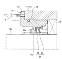
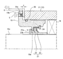
- FIG. 7 is a schematic partial cross-sectional view showing a first step of how to remove the sealing device of FIG. 2;
- FIG. 7 is a schematic partial cross-sectional view showing a second step of how to remove the seal device of FIG. 2;
- the typical fragmentary sectional view which shows the modification of the seal device of FIG.
- the schematic enlarged view of seal apparatus vicinity of the screw compressor which concerns on 3rd Embodiment of this invention.
- the schematic diagram which shows the positional relationship of the sleeve and bearing cover of the screw compressor which concerns on 3rd Embodiment of this invention.
- FIG. 1 is a partial cross-sectional view of a screw compressor (fluid machine) 1 according to a first embodiment of the present invention.
- screw compressor 1 is explained as an example of fluid machine, this art is applicable also to a screw expander which has the mechanism similar to it besides screw compressor 1.
- the screw compressor 1 includes a rotor casing 10 that defines a rotor chamber S1.
- the rotor casing 10 is divided into a main casing 11 accommodating the screw rotor 16 and a discharge casing 12 accommodating the bearing 17.
- the main casing 11 and the discharge casing 12 are fixed by screws and sealed with a packing (not shown) so as to prevent fluid from leaking therebetween.
- a lid 13 is attached to the discharge casing 12 on the opposite side of the main body casing 11.
- the lid 13 is fixed to the discharge casing 12 by screwing, and is sealed with a packing (not shown) so as to prevent fluid from leaking therebetween.
- the bearing chamber S2 which is a substantially enclosed space is defined by the lid 13 and the discharge casing 12.
- the screw compressor 1 also includes a motor casing 14 that defines a motor chamber S3 together with the rotor casing 10.
- the motor 15 is accommodated in the motor chamber S3.
- a pair of male and female screw rotors 16 are accommodated in the rotor chamber S1.
- a suction port 11 a is provided in the main body casing 11, and the suction port 11 a communicates with the left end in the drawing of the screw rotor 16.
- the fluid is supplied from the inlet 11 a into the rotor chamber S 1 and compressed by the screw rotor 16.
- the discharge port is not shown in FIG. 1, the fluid is discharged in the right direction in the figure of the screw rotor 16.
- the right side may be referred to as the discharge side
- the left side may be referred to as the suction side.
- the screw rotor 16 includes a screw rotor main body 16a in which teeth (not shown) of a screw are formed, and shaft portions 16b and 16c serving as rotation shafts thereof. Shaft portions 16b and 16c extend from the screw rotor main body 16a to the discharge side and the suction side, respectively.
- the discharge side shaft portion 16b penetrates the discharge casing 12 and extends to the bearing chamber S2, and is rotatably supported by the bearing 17 in the bearing chamber S2.
- the suction side shaft portion 16c penetrates the main body casing 11 from the rotor chamber S1 and extends to the motor chamber S3, and is mechanically connected to the motor 15 in the motor chamber S3.
- the shaft portion 16c on the suction side is rotatably supported by the bearing 18 in the bearing chamber S4.
- a bearing cover 19 which is a substantially cylindrical member disposed at intervals in the radial direction of the shaft portion 16 c and disposed around the shaft portion 16 c is provided.
- the bearing cover 19 is disposed on the opposite side to the rotor chamber S1 with respect to the bearing 18 in the axial direction of the shaft portion 16c. Therefore, the position of the bearing 18 is regulated by the bearing cover 19. Further, the bearing cover 19 is partially disposed radially inward of the rotor casing 10 to define the bearing chamber S4 together with the rotor casing 10.
- the bearing cover 19 is provided with a protruding portion 19a that protrudes radially inward from the inner surface thereof, and the seal device 21 is attached so as to be adjacent to the protruding portion 19a.
- the sealing device 21 is a device for sealing the bearing chamber S4.
- FIG. 2 shows a schematic enlarged view in the vicinity of the seal device 21 of FIG. Note that FIG. 2 is shown as a schematic diagram for the sake of clarity. Therefore, in FIG. 2, the shape, position, etc. of each configuration may not correspond to FIG.
- the seal device 21 includes a sleeve 22 which is a substantially cylindrical member fitted to the shaft portion 16c by interference fit, and a lip seal 23 which functions as a seal member.
- the sleeve 22 is provided with a convex portion (step portion) 22a having a contact surface 22b directed to the bearing 18 side at the end opposite to the side where the bearing 18 is in the axial direction of the shaft portion 16c.
- the convex portion 22a has a shape which is convex outward in the radial direction of the shaft portion 16c. In the present embodiment, the convex portion 22a is continuously provided at 360 ° around the shaft portion 16c.
- the lip seal 23 is disposed such that the lip portion is in contact with the sleeve 22 between the bearing cover 19 and the sleeve 22, and seals between the bearing cover 19 and the sleeve 22.
- a lip seal of Teflon (registered trademark) is adopted as the lip seal 23, and a sleeve of bearing steel is adopted as the sleeve 22.
- the type and material of the lip seal 23 and the sleeve 22 are not particularly limited.
- an O-ring 20 is disposed between the bearing cover 19 and the rotor casing 10 in the radial direction.
- the O-ring 20 has a function of preventing fluid from leaking between the bearing cover 19 and the rotor casing 10.
- the contact surface 22b of the convex portion 22a When viewed from the axial direction of the shaft portion 16c, the contact surface 22b of the convex portion 22a has a size in contact with the bearing cover 19 in the axial direction. That is, the interference width d between the sleeve 22 and the bearing cover 19 shown in FIG. 2 does not become 0 or less, and the height of the convex portion 22a is such that the bearing cover 19 and the sleeve 22 contact when the bearing cover 19 is pulled out. It is set. In other words, the height of the convex portion 22 a is a height at which the surface on which the bearing 18 is present (the contact surface 22 b) in the axial direction of the convex portion 22 a abuts on the bearing cover 19.
- the bearing cover 19 includes a takeout member 24 in contact with the lip seal 23 for withdrawing the lip seal 23 and the bearing cover 19 together.
- the takeout member 24 is a substantially annular member and is attached to the inside of the bearing cover 19. Further, the takeout member 24 is disposed on the same side as the lip chamber 23 in the axial direction of the shaft portion 16c as the rotor chamber S1 (see FIG. 1). That is, in FIG. 2, the takeout member 24 is disposed in the bearing chamber S ⁇ b> 4 on the side where the bearing is located with respect to the lip seal 23.
- the bearing cover 19 has a flange portion 19 b for being attached to the rotor casing 10.
- the flange portion 19 b is provided with a plurality of screw holes 19 c for the push bolt 5 (see FIG. 3) for removing the bearing cover 19 in the axial direction from the rotor casing 10.
- the screw hole 19c passes through the flange portion 19b.
- the push bolt 5 is prepared and inserted into a screw hole 19 c provided in the flange portion 19 b of the bearing cover 19.
- the push bolt 5 is longer than the thickness of the flange portion 19 b and has a length that penetrates the flange portion 19 b when inserted from the screw hole 19 c.
- the convex portion 22a of the sleeve is separated by a predetermined distance D from the protruding portion 19a of the bearing cover 19 in the axial direction of the shaft portion 16c. It is arranged on the 15 side. That is, the convex portion 22a of the sleeve 22 is disposed on the left side in the figure at a predetermined distance D apart from the protruding portion 19a of the bearing cover 19 in the axial direction of the shaft portion 16c.
- the protrusion 19 a of the bearing cover 19 abuts on the contact surface 22 b of the protrusion 22 a of the sleeve 22. If the hook 6 is further pulled in that state, the sleeve 22 is pushed and moved by the bearing cover 19, that is, the bearing cover 19, the lip seal 23, and the sleeve 22 are moved together. Accordingly, the bearing cover 19, the lip seal 23, and the sleeve 22 can be pulled out together.
- the hook 6 has been described in the case where the axial cross section has one L-shaped end, but the invention is not limited to this, and a plurality of the ends may be provided in the circumferential direction. Good. In this case, a plurality of ends of the hook 6 can be provided in rotational symmetry.
- the shaft can be easily heated without being thermally expanded by heating the sleeve 22 with a burner or the like. It can be pulled out from the part 16c. Therefore, there is no possibility that the bearing 18 is thermally deformed, and unnecessary replacement of the bearing 18 is eliminated.
- the sleeve 22 may be worn because the lip portion of the lip seal 23 and the sleeve 22 come into contact with each other. Therefore, since the replacement of the sleeve 22 is required as the sleeve 22 wears, a structure that allows the sleeve 22 to be easily removed without thermally deforming the bearing 18 is useful.
- the present embodiment by adjusting the height and the width of the convex portion 22 a of the sleeve 22 when designing the sleeve 22, it is possible to secure the required area of the contact surface 22 b. Therefore, it is easy to apply the required pulling force to the sleeve 22, and the sleeve can be pulled out more reliably.
- the bearing cover 19 when the bearing cover 19 is pulled out in the axial direction and removed, the bearing cover 19 abuts on the sleeve 22 so that the drawing force can be simultaneously applied to the bearing cover 19 and the sleeve 22. Therefore, the bearing cover 19 and the sleeve 22 can be removed together, and the removal operation can be simplified.
- the takeout member 24 abuts on the lip seal 23 so that a drawing force is simultaneously applied to the bearing cover 19 and the lip seal 23. it can. Accordingly, the bearing cover 19 and the lip seal 23 can be simultaneously removed, and the removal operation can be simplified.
- the push bolt 5 can be inserted into the screw hole 19c of the flange portion 19b, and the clearance C can be provided between the bearing cover 19 and the rotor casing 10 like a screw jack.
- the bearing cover 19 can be removed from the rotor casing 10 by inserting the hook 6 into the gap C and pulling it.
- the screw compressor 1 of this embodiment shown in FIG. 5 differs in the shape of the sleeve 22 from 1st Embodiment. Except for the configuration regarding the sleeve 22, the configuration is substantially the same as the configuration of the screw compressor 1 of the first embodiment of FIG. Therefore, the same parts as those in the configuration shown in FIG.
- the length of the sleeve 22 is longer than that of the first embodiment. Therefore, in a state where the sleeve 22 is mounted to the shaft portion 16c, the convex portion 22a of the sleeve 22 is not accommodated in the bearing cover 19 and is exposed to the outside.
- the end of the hook 7 having an L-shaped ( ⁇ -shaped) axial cross section is hooked to the contact surface 22b of the projection 22a.
- the tool 7 is pulled in the axial direction of the shaft portion 16c (see the arrow in FIG. 5), and a pullout force is directly applied to the sleeve 22 via the contact surface 22b. Therefore, the height of the convex portion 22a is such a height that the hook 7 can be hooked and a necessary pulling force can be applied.
- the necessary pullout force depends on the fitting strength between the sleeve 22 and the shaft portion 16c, but in the present embodiment, the height of the convex portion 22a is, for example, about 2 mm.
- a plurality of L-shaped (wedge-shaped) end portions of the convex portion 22 a and the hook 7 be provided in rotational symmetry. More preferably, the convex portion 22a is continuously provided around the shaft portion 16c.
- the sleeve 22 can be pulled out with certainty because the sleeve 22 can be directly pulled out.
- FIG. 6 shows a modification of the second embodiment.
- the recess 22 c is provided in the sleeve 22 instead of the protrusion 22 a (see FIG. 5).
- the recess 22 c has a concave shape inward in the radial direction of the shaft portion 16 c.
- the depth of the recess 22 c is about half the thickness of the sleeve 22. In the present embodiment, for example, the depth of the recess 22c is about 2 mm with respect to the sleeve 22 having a thickness of 5 mm.
- the pulling-out force can be applied to the sleeve 22 via the contact surface 22d of the recess 22c.
- the recess 22c can be easily formed by cutting the existing sleeve or the like.
- the screw compressor 1 of the present embodiment shown in FIGS. 7 and 8 differs from the first embodiment in the shape of the bearing cover 19 and the shape of the sleeve 22. Except for the configuration regarding the bearing cover 19 and the sleeve 22, the configuration is substantially the same as the configuration of the screw compressor 1 of the first embodiment of FIG. 2. Therefore, the same parts as those in the configuration shown in FIG. In FIG. 8, only the protruding portion 19 d of the bearing cover 19 and the sleeve 22 are schematically shown in order to make the illustration clear.
- the convex portions 22a of the sleeve 22 are provided at a plurality of positions (four in the present embodiment) around the axial center when viewed from the motor 15 side in the extending direction of the sleeve 22.
- the projecting portions 19 d of the bearing cover 19 are also provided at a plurality of positions (four in the present embodiment) around the axis center when viewed from the extending direction of the sleeve 22.
- the protrusion 22a can move to a position where the contact surface 22b on the side with the bearing 18 in the axial direction of the protrusion 22a contacts the protrusion 19d of the bearing cover 19 when the bearing cover 19 is pulled out in the axial direction. .
- the shapes of the protrusion 22 a and the protrusion 19 d may not be continuously provided at 360 °.
- the protrusion 22 a and the protrusion 19 d are provided so as to be rotationally symmetrical around the axial center. Therefore, the number of the protrusions 22a and the corresponding protrusions 19a is not particularly limited.
- this invention is not limited to the said form, In the range of this invention, it can change variously and can implement. For example, an appropriate combination of the contents of the individual embodiments may be used as an embodiment of the present invention. Further, for example, in the third embodiment, although a plurality of protrusions 19 d around the axis as shown in FIG. 8 are provided on the bearing cover 19, such plurality of protrusions 19 d are changed to the bearing cover 19. Alternatively, it may be separately provided at the tip of the cylindrical hook.
- Screw compressor (fluid machine) Reference Signs List 5 push bolt 6, 7 hook 10 rotor casing 11 main casing 11a suction port 12 discharge casing 13 lid 14 motor casing 15 motor 16 screw rotor 16a screw rotor main body 16b, 16c shaft portion 17, 18 bearing 19 bearing cover 19a, 19d Protrusion 19b Flange 19c Screw hole 20 O-ring 21 Seal device 22 Sleeve 22a Convex part (step part) 22b contact surface 22c recess (step) 23 lip seal 24 takeout member
Landscapes
- Engineering & Computer Science (AREA)
- General Engineering & Computer Science (AREA)
- Mechanical Engineering (AREA)
- Applications Or Details Of Rotary Compressors (AREA)
- Sealing With Elastic Sealing Lips (AREA)
Abstract
スクリュ圧縮機1は、スクリュロータ本体16aを収容するロータ室S1を画定するロータケーシング10と、スクリュロータ本体16aからロータケーシング10を貫通して延びる軸部16cと、ロータ室S1外で軸部16cを回転可能に支持する軸受18と、軸部16cの径方向に間隔をおいて軸部16cの周囲に配置される筒状部材であり、軸部16cの軸方向において軸受18に対してロータ室S1と反対側に配置され、軸受18の移動を規制する軸受カバー19と、軸部16cに締まり嵌めによって嵌合される筒状部材であるスリーブ22と、軸受カバー19とスリーブ22との間を軸封するリップシール23とを備える。スリーブ22には、軸方向において軸受18のある側と反対側の部分に、径方向の段差を有する段差部22aが設けられている。
Description
本発明は、流体機械およびそのスリーブの取り外し方法に関する。
流体機械の一例であるスクリュ圧縮機では、軸部がロータ室の外部まで延びているため、ロータ室を画定するロータケーシングに貫通孔が設けられる。そのため、貫通孔を通じてロータ室の内部から外部へ流体が漏出することを防止するためにシール装置が必要である。そのようなシール装置を備えたスクリュ圧縮機が、例えば特許文献1に開示されている。
特許文献1のスクリュ圧縮機では、低圧側の軸受と電動機との間にシール装置が配置されている。このシール装置は、メンテナンス性向上の観点から、ロータケーシングに対して着脱可能な軸受カバーに収容されている。即ち、メンテナンスの際には、軸受カバーを取り外し、シール装置を交換できる。
スクリュ圧縮機のシール装置の例としては、非接触型シールまたは接触型シール等が挙げられる。特に近年、接触型のシールとして、耐久性能、高速性能、および耐圧性能に優れ、かつ、安価であるテフロン(登録商標)のリップシールが主流となっている。この材質は、テフロン(登録商標)にカーボンやガラス等の充填材を入れたものである。この材質は、リップシールの耐摩耗性を向上させる一方、リップシールの相手材(軸部材)を摩耗させることがある。そこで、リップシールの接触する相手(軸部)には、焼き入れ鋼または軸受鋼等の硬度の高いスリーブが設置されることが多い。
特許文献1に開示されたスクリュ圧縮機のシール装置は、スクリュロータの軸部にスリーブが嵌め込まれ、そのスリーブにリップシールが接触する構造を有している。通常、このような構造では、軸部とスリーブとの間からの流体の漏出を防止するため、軸部とスリーブとは締り嵌めによって嵌合されている。
締り嵌めによって嵌合されているスリーブを取り外すことは容易ではない。そのようなスリーブを取り外すときは、バーナでスリーブを炙るなどしてスリーブを熱膨張させる必要があり、作業が煩雑である。さらに、そのようなスリーブの取り外し作業では、スリーブと隣接した軸受も加熱されるおそれがある。軸受は過度に加熱されると変形し、寸法が変化して再使用できなくなる場合があり、その場合、軸受を交換する必要がある。従って、スリーブの交換に加えて軸受の交換に伴う工数およびコストが増える。
本発明は、シール装置のスリーブを容易に取り外すことができる流体機械およびそのスリーブの取り外し方法を提供することを課題とする。
本発明の第1の態様は、スクリュロータ本体を収容するロータ室を画定するロータケーシングと、前記スクリュロータ本体から前記ロータケーシングを貫通して延びる軸部と、前記ロータ室外で前記軸部を回転可能に支持する軸受と、前記軸部の径方向に間隔をおいて当該軸部の周囲に配置される筒状部材であり、前記軸部の軸方向において前記軸受に対して前記ロータ室と反対側に配置され、前記軸受の移動を規制する軸受カバーと、前記軸部に締まり嵌めによって嵌合される筒状部材であるスリーブと、前記軸受カバーと前記スリーブとの間を軸封するリップシールとを備え、前記スリーブには、前記軸方向において前記軸受のある側と反対側の部分に、前記径方向の段差を有する段差部が設けられている、流体機械を提供する。
この構成によれば、スリーブの段差部を介して軸方向の引き抜き力をスリーブに加えることができるため、スリーブをバーナ等で加熱して熱膨張させることなく容易に軸部から引き抜くことができる。そのため、軸受が熱変形するおそれもなく、不要な軸受の交換はなくなる。上記構成では、少なくともリップシールとスリーブとによってシール装置が構成される。このようなシール装置では、リップシールとスリーブとが接触するため、スリーブが摩耗することがある。従って、スリーブの摩耗に伴い、スリーブの交換が必要となることから、このように軸受を熱変形させることなくスリーブを容易に取り外すことのできる構造は有用である。
前記段差部は、前記径方向内側へ凹の形状を有する凹部であってもよい。
この構成によれば、凹部を介して軸方向の引き抜き力をスリーブに加えることができる。特に、段差部が凹部であるため、既存のスリーブを切削加工するなどして段差部を簡易に形成できる。
前記段差部は、前記径方向外側へ凸の形状を有する凸部であってもよい。
この構成によれば、凸部を介して軸方向の引き抜き力をスリーブに加えることができる。特に、段差部が凸部であるため、凸部の高さや幅を調整することで必要な段差を確保できる。そのため、スリーブに対して必要な引き抜き力を加え易く、凸部に対する引き抜き力を付加する種々の方法でスリーブを引き抜くことができる。
前記軸受カバーを前記軸方向に引き抜く際、前記凸部の高さは、前記軸受カバーと当接する高さであってもよい。また、前記凸部の高さは、前記凸部の前記軸方向において前記軸受のある側の面が前記軸受カバーと当接することのできる高さであってもよい。また、前記凸部は、前記軸受カバーを前記軸方向に引き抜く際、前記凸部の前記軸方向において前記軸受のある側の面が前記軸受カバーと当接する位置に、設けられてもよい。
これらの構成によれば、軸受カバーを軸方向に引き抜いて取り外すとき、または、スリーブを軸方向に引き抜いて取り外すとき、軸受カバーとスリーブとが当接するため、軸受カバーとスリーブとに同時に引き抜き力を作用させることができる。従って、軸受カバーとスリーブとを一緒に取り外すことができ、取り外し作業を簡略化できる。
前記リップシールと前記軸受カバーとを一緒に引き抜くことを可能にする取出部材をさらに備え、前記取出部材は、前記軸受カバーに取り付けられ、前記軸方向において前記リップシールに対して前記ロータ室と同じ側に配置され、前記軸受カバーとともに前記軸方向に移動して前記リップシールと当接してもよい。
この構成によれば、軸受カバーを軸方向に引き抜いて取り外すとき、取出部材がリップシールと当接するため、軸受カバーとリップシールとに同時に引き抜き力を作用させることができる。従って、軸受カバーとリップシールとを一緒に取り外すことができ、取り外し作業を簡略化できる。
前記軸受カバーは、前記ロータケーシングに取り付けられるためのフランジ部を有し、前記フランジ部には、前記軸受カバーを前記ロータケーシングから取り外すための押しボルト用のねじ孔が設けられていてもよい。
この構成によれば、押しボルトをフランジ部のねじ孔に挿入し、スクリュジャッキのようにして軸受カバーとロータケーシングとの間に隙間を設けることができる。そしてその隙間を利用して軸受カバーを引っ張ることで軸受カバーをロータケーシングから取り外すことができる。
本発明の第2の態様は、前記流体機械が備えているスリーブの取り外し方法であって、前記スリーブの前記段差部に引掛具を引掛け、前記引掛具を前記軸方向に引っ張ることで前記スリーブを引き抜く、スリーブの取り外し方法を提供する。
この方法によれば、流体機械において、スリーブが段差部を備えるため、段差部にそれと係合する任意形状の引掛具を引掛け、引掛具を介して引き抜き力をスリーブに加えることができる。従って、スリーブを容易に取り外すことができる。
本発明の第3の態様は、スクリュロータ本体を収容するロータ室を画定するロータケーシングと、前記スクリュロータ本体から前記ロータケーシングを貫通して延びる軸部と、前記ロータ室外で前記軸部を回転可能に支持する軸受と、前記軸部の径方向に間隔をおいて当該軸部の周囲に配置される筒状部材であり、前記軸部の軸方向において前記軸受に対して前記ロータ室と反対側に配置され、前記軸受の移動を規制する軸受カバーと、前記軸部に締まり嵌めによって嵌合される筒状部材であるスリーブと、前記軸受カバーと前記スリーブとの間を軸封するリップシールとを備え、前記スリーブには、前記軸方向において前記軸受のある側と反対側の部分に、前記径方向の段差を有する段差部が設けられており、前記段差部は、前記径方向外側へ凸の形状を有する凸部であり、前記凸部は、前記軸受カバーを前記軸方向に引き抜く際、前記凸部の前記軸方向において前記軸受のある側の面が前記軸受カバーと当接する位置に、設けられており、前記リップシールと前記軸受カバーとを一緒に引き抜くことを可能にする取出部材をさらに備え、前記取出部材は、前記軸受カバーに取り付けられており、前記軸方向において前記リップシールに対して前記ロータ室と同じ側に配置され、前記軸受カバーは、前記ロータケーシングに取り付けられるためのフランジ部を有し、前記フランジ部には、前記軸受カバーを前記ロータケーシングから前記軸方向へ取り外すための押しボルト用のねじ孔が設けられている、流体機械におけるスリーブの取り外し方法であって、前記押しボルト用のねじ孔に押しボルトを挿入することで、前記軸受カバーと前記ロータケーシングとの間の隙間を拡げ、前記隙間に引掛具を引掛け、前記引掛具を前記軸方向に引っ張ることで、前記軸受カバーを前記軸方向に引っ張り、前記軸受カバーの移動に伴って前記取出部材が前記リップシールと当接して前記リップシールを前記軸受カバーとともに前記軸方向に移動させ、前記軸受カバーを前記軸方向に移動させることで、前記軸受カバーを前記スリーブの前記凸部と当接させ、前記軸受カバーと前記リップシールと前記スリーブとを一緒に取り外す、スリーブの取り外し方法を提供する。
この方法によれば、流体機械において、押しボルトおよび引掛具を利用してロータケーシングから軸受カバーを容易に取り外すことができ、軸受カバーを軸方向に引っ張ることで、軸受カバーとリップシールとスリーブと一緒に取り外すことができる。従って、取り外し作業を簡略化できる。
本発明の第4の態様は、スクリュロータ本体を収容するロータ室を画定するロータケーシングと、前記スクリュロータ本体から前記ロータケーシングを貫通して延びる軸部と、前記ロータ室外で前記軸部を回転可能に支持する軸受と、前記軸部の径方向に間隔をおいて当該軸部の周囲に配置される筒状部材であり、前記軸部の軸方向において前記軸受に対して前記ロータ室と反対側に配置され、前記軸受の移動を規制する軸受カバーと、前記軸部に締まり嵌めによって嵌合される筒状部材であるスリーブと、前記軸受カバーと前記スリーブとの間を軸封するリップシールとを備え、前記スリーブには、前記軸方向において前記軸受のある側と反対側の部分に、前記径方向の段差を有する段差部が設けられており、前記段差部は、前記径方向外側へ凸の形状を有する凸部であり、前記凸部は、前記軸受カバーを前記軸方向に引き抜く際、前記凸部の前記軸方向において前記軸受のある側の面が前記軸受カバーと当接する位置に、設けられており、前記リップシールと前記軸受カバーとを一緒に引き抜くことを可能にする取出部材をさらに備え、前記取出部材は、前記軸受カバーに取り付けられており、前記軸方向において前記リップシールに対して前記ロータ室と同じ側に配置され、前記軸受カバーは、前記ロータケーシングに取り付けられるためのフランジ部を有し、前記フランジ部には、前記軸受カバーを前記ロータケーシングから前記軸方向へ取り外すための押しボルト用のねじ孔が設けられている、流体機械における前記スリーブの取り外す方法であって、前記押しボルト用のねじ孔に押しボルトを挿入することで、前記軸受カバーを前記軸方向へ移動させ、前記軸受カバーの移動に伴って前記取出部材が前記リップシールと当接して前記リップシールを前記軸受カバーとともに前記軸方向に移動させ、前記軸受カバーを前記軸方向に移動させることで、前記軸受カバーを前記スリーブの前記凸部と当接させ、前記軸受カバーと前記リップシールと前記スリーブとを一緒に取り外す、スリーブの取り外し方法を提供する。
この方法によれば、流体機械において、押しボルトを利用してロータケーシングから軸受カバーを容易に取り外すことができ、軸受カバーを軸方向に引っ張ることで、軸受カバーとリップシールとスリーブと一緒に取り外すことができる。従って、取り外し作業を簡略化できる。
本発明によれば、流体機械において、シール装置のスリーブが段差部を備えるため、段差部を介して引抜き力を加えることでスリーブを容易に取り外すことができる。
以下、添付図面を参照して本発明の実施形態を説明する。
(第1実施形態)
図1は、本発明の第1実施形態に係るスクリュ圧縮機(流体機械)1の部分断面図である。以下では、流体機械の一例としてスクリュ圧縮機1について説明するが、本技術はスクリュ圧縮機1以外にそれと同様の機構を有するスクリュ膨張機にも適用可能である。
図1は、本発明の第1実施形態に係るスクリュ圧縮機(流体機械)1の部分断面図である。以下では、流体機械の一例としてスクリュ圧縮機1について説明するが、本技術はスクリュ圧縮機1以外にそれと同様の機構を有するスクリュ膨張機にも適用可能である。
スクリュ圧縮機1は、ロータ室S1を画定するロータケーシング10を備える。詳細には、ロータケーシング10は、スクリュロータ16を収容する本体ケーシング11と、軸受17を収容する吐出ケーシング12とに分割される。本体ケーシング11および吐出ケーシング12はねじ止めによって固定されており、これらの間から流体が漏出しないように図示されないパッキンで密閉されている。吐出ケーシング12には、本体ケーシング11と反対側に蓋体13が取り付けられている。蓋体13は、吐出ケーシング12とねじ止めによって固定されており、これらの間から流体が漏出しないように図示されないパッキンで密閉されている。従って、蓋体13と吐出ケーシング12とによって、実質的に密閉空間となる軸受室S2が画定されている。また、スクリュ圧縮機1は、ロータケーシング10とともにモータ室S3を画定するモータケーシング14を備える。モータ室S3内には、モータ15が収容されている。
ロータ室S1の内部には、雌雄一対のスクリュロータ16が収容されている。本体ケーシング11には、吸入口11aが設けられており、吸入口11aはスクリュロータ16の図において左端部に連通している。流体は、吸入口11aからロータ室S1内に供給され、スクリュロータ16によって圧縮される。なお、図1では吐出口が図示されていないが、スクリュロータ16の図において右方向に流体は吐出される。以降、スクリュロータ16の図において右側を吐出側、左側を吸込側という場合がある。
スクリュロータ16は、スクリュの歯(不図示)を形成したスクリュロータ本体16aと、その回転軸となる軸部16b,16cとを備える。スクリュロータ本体16aからは、吐出側と吸込側のそれぞれに軸部16b,16cが延びている。吐出側の軸部16bは、吐出ケーシング12を貫通して軸受室S2まで延び、軸受室S2内にて軸受17によって回転可能に支持されている。吸込側の軸部16cは、ロータ室S1から本体ケーシング11を貫通してモータ室S3まで延び、モータ室S3内にてモータ15に機械的に接続されている。また、吸込側の軸部16cは、軸受室S4内にて軸受18によって回転可能に支持されている。
本体ケーシング11において、軸受18に隣接した位置には、軸部16cの径方向に間隔をおいて軸部16cの周囲に配置される概ね筒状の部材である軸受カバー19が設けられている。詳細には、軸受カバー19は、軸部16cの軸方向において軸受18に対してロータ室S1と反対側に配置されている。そのため、軸受カバー19によって軸受18の位置が規制されている。また、軸受カバー19は、部分的にロータケーシング10の径方向内側に配置されてロータケーシング10と共に軸受室S4を画定している。軸受カバー19には、その内面から径方向内側に突出した突出部19aが設けられており、突出部19aに隣接するようにシール装置21が取り付けられている。シール装置21は、軸受室S4を密閉するための装置である。
図2は、図1のシール装置21付近の模式的な拡大図を示している。なお、図2は説明を明瞭にするため模式図として示されている。従って、図2では、各構成の形状および位置等が図1と対応していない場合がある。
シール装置21は、軸部16cに締まり嵌めによって嵌合されている概ね筒状の部材であるスリーブ22と、シール部材として機能するリップシール23とを備える。なお、締まり嵌めの定義はJIS B 0401の規定に準じるものとする。スリーブ22には、軸部16cの軸方向において軸受18のある側と反対側の端部に、軸受18側に向けた当接面22bを有する凸部(段差部)22aが設けられている。凸部22aは、軸部16cの径方向外側へ凸の形状を有する。本実施形態では、凸部22aは、軸部16cの周囲に360°連続的に設けられている。リップシール23は、軸受カバー19とスリーブ22との間においてリップ部がスリーブ22と接触するように配置され、軸受カバー19とスリーブ22との間を軸封する。本実施形態では、リップシール23としてテフロン(登録商標)のリップシールを採用し、スリーブ22として軸受鋼のスリーブを採用している。ただし、本技術の適用に際し、リップシール23およびスリーブ22の種類および材質は特に限定されない。
また、径方向において軸受カバー19とロータケーシング10との間にはOリング20が配置されている。Oリング20は、軸受カバー19とロータケーシング10との間から流体が漏出することを防止する機能を有している。
軸部16cの軸方向から見ると、凸部22aの当接面22bは、軸受カバー19と該軸方向で接する大きさである。即ち、図2に示すスリーブ22と軸受カバー19との干渉幅dは0以下とならず、軸受カバー19を引き抜く際に軸受カバー19とスリーブ22とが当接するように凸部22aの高さは設定されている。換言すると、凸部22aの高さは、凸部22aの軸方向において軸受18のある側の面(当接面22b)が軸受カバー19と当接する高さである。
軸受カバー19は、リップシール23と当接してリップシール23と軸受カバー19とを一緒に引き抜くための取出部材24を備える。取出部材24は、略環状の部材であり、軸受カバー19の内側に取り付けられている。また、取出部材24は、軸部16cの軸方向においてリップシール23に対してロータ室S1(図1参照)と同じ側に配置されている。即ち、図2において、取出部材24は、リップシール23に対して軸受のある側の軸受室S4内に配置されている。
軸受カバー19は、ロータケーシング10に取り付けられるためのフランジ部19bを有している。フランジ部19bには、軸受カバー19をロータケーシング10から軸方向へ取り外すための押しボルト5(図3参照)用のねじ孔19cが複数個設けられている。ねじ孔19cはフランジ部19bを貫通している。
以下では、上記構成を有するスクリュ圧縮機1のシール装置21において、スリーブ22を取り外す方法の流れを説明する。なお、押しボルト5は複数設けられているが代表的に一つを取り上げて説明する。
まず、図3に示すように、押しボルト5を準備し、軸受カバー19のフランジ部19bに設けられたねじ孔19cに挿入する。押しボルト5は、フランジ部19bの厚みよりも長く、ねじ孔19cから挿入した際にフランジ部19bを貫通する長さである。図3に示す押しボルト5をねじ孔19cに挿入する前の状態では、スリーブの凸部22aは、軸部16cの軸方向において、軸受カバー19の突出部19aよりも所定距離Dを離してモータ15側に配置されている。即ち、スリーブ22の凸部22aは、軸部16cの軸方向において、軸受カバー19の突出部19aよりも所定距離Dを離して図において左側に配置されている。
次に、図4に示すように、押しボルト5を深く挿入してロータケーシング10に達した後、更にねじ込むと、軸受カバー19とロータケーシング10との間の隙間Cが拡がる。発生した隙間Cに端部の軸方向断面がL字型(鉤形)の引掛具6の当該端部を挿入し、軸受カバー19に引掛具6を引掛ける。そして、引掛具6を軸受カバー19に引掛けた状態で引掛具6を軸部16cの軸方向(図4の矢印参照)に引っ張ることで引抜き力を作用させて、軸受カバー19が該方向に移動される。軸受カバー19が該方向に移動されると、取出部材24に押されてリップシール23も一緒に移動される。所定距離D(図3参照)だけ移動されると、軸受カバー19の突出部19aがスリーブ22の凸部22aの当接面22bに当接する。その状態でさらに引掛具6を引っ張り続けると、スリーブ22は軸受カバー19に押されて移動され、即ち、軸受カバー19とリップシール23とスリーブ22とが一緒に移動される。従って、軸受カバー19とリップシール23とスリーブ22とを一緒に引き抜くことができる。ここで、引掛具6は、軸方向断面がL字型の端部が一つの場合で説明しているがこれに限らず、当該端部を周方向に複数個備えているものであってもよい。この場合、引掛具6の複数の端部が回転対称に設けることができる。
以下、本実施形態によって得られる効果を説明する。
本実施形態によれば、スリーブ22の凸部22aの当接面22bを介して引き抜き力をスリーブ22に加えることができるため、スリーブ22をバーナ等で加熱して熱膨張させることなく容易に軸部16cから引き抜くことができる。そのため、軸受18が熱変形するおそれもなく、不要な軸受18の交換がなくなる。特に、リップシール23を用いたシール装置21では、リップシール23のリップ部とスリーブ22とが接触するため、スリーブ22が摩耗することがある。従って、スリーブ22の摩耗に伴い、スリーブ22の交換が必要となることから、このように軸受18を熱変形させることなくスリーブ22を容易に取り外すことのできる構造は有用である。
また、本実施形態によれば、スリーブ22の設計の際にスリーブ22の凸部22aの高さや幅を調整することで必要な当接面22bの面積を確保できる。そのため、スリーブ22に対して必要な引き抜き力を加え易く、一層確実にスリーブを引き抜くことができる。
また、本実施形態によれば、軸受カバー19を軸方向に引き抜いて取り外すとき、軸受カバー19がスリーブ22と当接するため、軸受カバー19とスリーブ22とに同時に引き抜き力を作用させることができる。従って、軸受カバー19とスリーブ22とを一緒に取り外すことができ、取り外し作業を簡略化できる。
また、本実施形態によれば、軸受カバー19を軸方向に引き抜いて取り外すとき、取出部材24がリップシール23と当接するため、軸受カバー19とリップシール23とに同時に引き抜き力を作用させることができる。従って、軸受カバー19とリップシール23とを同時に取り外すことができ、取り外し作業を簡略化できる。
また、本実施形態によれば、押しボルト5をフランジ部19bのねじ孔19cに挿入し、スクリュジャッキのようにして軸受カバー19とロータケーシング10との間に隙間Cを設けることができる。そしてその隙間Cに引掛具6を挿入して引っ張ることで軸受カバー19をロータケーシング10から取り外すことができる。
(第2実施形態)
図5に示す本実施形態のスクリュ圧縮機1は、スリーブ22の形状が第1実施形態とは異なる。スリーブ22に関する構成以外は、図2の第1実施形態のスクリュ圧縮機1の構成と実質的に同じである。従って、図2に示した構成と同じ部分については同じ符号を付して説明を省略する。
図5に示す本実施形態のスクリュ圧縮機1は、スリーブ22の形状が第1実施形態とは異なる。スリーブ22に関する構成以外は、図2の第1実施形態のスクリュ圧縮機1の構成と実質的に同じである。従って、図2に示した構成と同じ部分については同じ符号を付して説明を省略する。
本実施形態では、スリーブ22の長さが第1実施形態よりも長い。従って、スリーブ22が軸部16cに装着された状態で、スリーブ22の凸部22aは、軸受カバー19内に収容されず、外部に露出している。
本実施形態では、スリーブ22を取り外すとき、端部の軸方向断面がL字型(鉤形)の引掛具7の当該端部を凸部22aの当接面22bに引掛けた状態で、引掛具7を軸部16cの軸方向(図5の矢印参照)に引っ張り、当接面22bを介してスリーブ22に直接引き抜き力を作用させる。そのため、凸部22aの高さは、引掛具7を引掛け、必要な引き抜き力を作用させることができる程度の高さである。必要な引き抜き力はスリーブ22と軸部16cとの嵌合強度に依存するが、本実施形態では、凸部22aの高さは例えば2mm程度である。また、スリーブ22に引き抜き力を均等に作用させるべく、凸部22a及び引掛具7のL字型(鉤形)の端部は、回転対称に複数個設けられていることが好ましい。さらに好ましくは、凸部22aは軸部16cの周囲に連続的に設けられている。
本実施形態によれば、スリーブ22に直接引き抜き力を作用させることができるため、確実にスリーブ22を引き抜くことができる。
図6は、第2実施形態の変形例を示している。本変形例では、凸部22a(図5参照)ではなく凹部22cがスリーブ22に設けられている。凹部22cは、軸部16cの径方向内側へ凹の形状を有する。凹部22cの深さは、スリーブ22の板厚の半分程度である。本実施形態では、例えば5mmの板厚のスリーブ22に対して、凹部22cの深さは2mm程度である。
本変形例によれば、凹部22cの当接面22dを介して引き抜き力をスリーブ22に加えることができる。特に、スリーブ22を形成する際、既存のスリーブを切削加工するなどして凹部22cを簡易に形成できる。
(第3実施形態)
図7及び図8に示す本実施形態のスクリュ圧縮機1は、軸受カバー19の形状およびスリーブ22の形状が第1実施形態とは異なる。軸受カバー19およびスリーブ22に関する構成以外は、図2の第1実施形態のスクリュ圧縮機1の構成と実質的に同じである。従って、図2に示した構成と同じ部分については同じ符号を付して説明を省略する。なお、図8では、図示を明瞭にするため、軸受カバー19の突出部19dと、スリーブ22のみを模式的に示している。
図7及び図8に示す本実施形態のスクリュ圧縮機1は、軸受カバー19の形状およびスリーブ22の形状が第1実施形態とは異なる。軸受カバー19およびスリーブ22に関する構成以外は、図2の第1実施形態のスクリュ圧縮機1の構成と実質的に同じである。従って、図2に示した構成と同じ部分については同じ符号を付して説明を省略する。なお、図8では、図示を明瞭にするため、軸受カバー19の突出部19dと、スリーブ22のみを模式的に示している。
本実施形態では、スリーブ22の凸部22aは、スリーブ22の延びる方向のモータ15側から見て、軸中心まわりの複数の位置に(本実施形態では4つ)設けられている。また、軸受カバー19の突出部19dもスリーブ22の延びる方向から見て軸中心まわりの複数の位置に(本実施形態では4つ)設けられている。凸部22aは、軸受カバー19を軸方向に引き抜く際、凸部22aの軸方向において軸受18のある側の当接面22bが軸受カバー19の突出部19dと当接する位置に移動することができる。このように、凸部22aおよび突出部19dの形状は、360°連続的に設けられていなくてもよい。好ましくは、凸部22aおよび突出部19dは、軸中心まわりに回転対称に設けられている。従って、凸部22aおよび対応する突出部19aの数は特に限定されない。
以上より、本発明の具体的な実施形態およびその変形例について説明したが、本発明は上記形態に限定されるものではなく、この発明の範囲内で種々変更して実施することができる。例えば、個々の実施形態の内容を適宜組み合わせたものを、この発明の一実施形態としてもよい。また、例えば、第3実施形態においては、図8に示すような軸心周りの複数の突出部19dを軸受カバー19に設けているが、このような複数の突出部19dを軸受カバー19に変えて、別途円筒状の引掛具の先端部に設けるようにしてもよい。
1 スクリュ圧縮機(流体機械)
5 押しボルト
6,7 引掛具
10 ロータケーシング
11 本体ケーシング
11a 吸入口
12 吐出ケーシング
13 蓋体
14 モータケーシング
15 モータ
16 スクリュロータ
16a スクリュロータ本体
16b,16c 軸部
17,18 軸受
19 軸受カバー
19a,19d 突出部
19b フランジ部
19c ねじ孔
20 Oリング
21 シール装置
22 スリーブ
22a 凸部(段差部)
22b 当接面
22c 凹部(段差部)
23 リップシール
24 取出部材
5 押しボルト
6,7 引掛具
10 ロータケーシング
11 本体ケーシング
11a 吸入口
12 吐出ケーシング
13 蓋体
14 モータケーシング
15 モータ
16 スクリュロータ
16a スクリュロータ本体
16b,16c 軸部
17,18 軸受
19 軸受カバー
19a,19d 突出部
19b フランジ部
19c ねじ孔
20 Oリング
21 シール装置
22 スリーブ
22a 凸部(段差部)
22b 当接面
22c 凹部(段差部)
23 リップシール
24 取出部材
Claims (11)
- スクリュロータ本体を収容するロータ室を画定するロータケーシングと、
前記スクリュロータ本体から前記ロータケーシングを貫通して延びる軸部と、
前記ロータ室外で前記軸部を回転可能に支持する軸受と、
前記軸部の径方向に間隔をおいて当該軸部の周囲に配置される筒状部材であり、前記軸部の軸方向において前記軸受に対して前記ロータ室と反対側に配置され、前記軸受の移動を規制する軸受カバーと、
前記軸部に締まり嵌めによって嵌合される筒状部材であるスリーブと、
前記軸受カバーと前記スリーブとの間を軸封するリップシールとを備え、
前記スリーブには、前記軸方向において前記軸受のある側と反対側の部分に、前記径方向の段差を有する段差部が設けられている、流体機械。 - 前記段差部は、前記径方向内側へ凹の形状を有する凹部である、請求項1に記載の流体機械。
- 前記段差部は、前記径方向外側へ凸の形状を有する凸部である、請求項1に記載の流体機械。
- 前記軸受カバーを前記軸方向に引き抜く際、前記凸部の高さは、前記軸受カバーと当接する高さである、請求項3に記載の流体機械。
- 前記凸部の高さは、前記凸部の前記軸方向において前記軸受のある側の面が前記軸受カバーと当接することのできる高さである、請求項3に記載の流体機械。
- 前記凸部は、前記軸受カバーを前記軸方向に引き抜く際、前記凸部の前記軸方向において前記軸受のある側の面が前記軸受カバーと当接する位置に、設けられる、請求項3に記載の流体機械。
- 前記リップシールと前記軸受カバーとを一緒に引き抜くことを可能にする取出部材をさらに備え、
前記取出部材は、前記軸受カバーに取り付けられており、前記軸方向において前記リップシールに対して前記ロータ室と同じ側に配置され、前記軸受カバーとともに前記軸方向に移動して前記リップシールと当接する、請求項4から請求項6のいずれか1項に記載の流体機械。 - 前記軸受カバーは、前記ロータケーシングに取り付けられるためのフランジ部を有し、
前記フランジ部には、前記軸受カバーを前記ロータケーシングから前記軸方向へ取り外すための押しボルト用のねじ孔が設けられている、請求項4から請求項6のいずれか1項に記載の流体機械。 - 請求項1から請求項6のいずれか1項に記載の流体機械が備えているスリーブの取り外し方法であって、
前記スリーブの前記段差部に引掛具を引掛け、前記引掛具を前記軸方向に引っ張ることで前記スリーブを引き抜く、スリーブの取り外し方法。 - スクリュロータ本体を収容するロータ室を画定するロータケーシングと、
前記スクリュロータ本体から前記ロータケーシングを貫通して延びる軸部と、
前記ロータ室外で前記軸部を回転可能に支持する軸受と、
前記軸部の径方向に間隔をおいて当該軸部の周囲に配置される筒状部材であり、前記軸部の軸方向において前記軸受に対して前記ロータ室と反対側に配置され、前記軸受の移動を規制する軸受カバーと、
前記軸部に締まり嵌めによって嵌合される筒状部材であるスリーブと、
前記軸受カバーと前記スリーブとの間を軸封するリップシールとを備え、
前記スリーブには、前記軸方向において前記軸受のある側と反対側の部分に、前記径方向の段差を有する段差部が設けられており、
前記段差部は、前記径方向外側へ凸の形状を有する凸部であり、
前記凸部は、前記軸受カバーを前記軸方向に引き抜く際、前記凸部の前記軸方向において前記軸受のある側の面が前記軸受カバーと当接する位置に、設けられており、
前記リップシールと前記軸受カバーとを一緒に引き抜くことを可能にする取出部材をさらに備え、
前記取出部材は、前記軸受カバーに取り付けられており、前記軸方向において前記リップシールに対して前記ロータ室と同じ側に配置され、 前記軸受カバーは、前記ロータケーシングに取り付けられるためのフランジ部を有し、
前記フランジ部には、前記軸受カバーを前記ロータケーシングから前記軸方向へ取り外すための押しボルト用のねじ孔が設けられている、流体機械におけるスリーブの取り外し方法であって、
前記押しボルト用のねじ孔に押しボルトを挿入することで、前記軸受カバーと前記ロータケーシングとの間の隙間を拡げ、
前記隙間に引掛具を引掛け、前記引掛具を前記軸方向に引っ張ることで、前記軸受カバーを前記軸方向に引っ張り、前記軸受カバーの移動に伴って前記取出部材が前記リップシールと当接して前記リップシールを前記軸受カバーとともに前記軸方向に移動させ、
前記軸受カバーを前記軸方向に移動させることで、前記軸受カバーを前記スリーブの前記凸部と当接させ、前記軸受カバーと前記リップシールと前記スリーブとを一緒に取り外す、スリーブの取り外し方法。 - スクリュロータ本体を収容するロータ室を画定するロータケーシングと、
前記スクリュロータ本体から前記ロータケーシングを貫通して延びる軸部と、
前記ロータ室外で前記軸部を回転可能に支持する軸受と、
前記軸部の径方向に間隔をおいて当該軸部の周囲に配置される筒状部材であり、前記軸部の軸方向において前記軸受に対して前記ロータ室と反対側に配置され、前記軸受の移動を規制する軸受カバーと、
前記軸部に締まり嵌めによって嵌合される筒状部材であるスリーブと、
前記軸受カバーと前記スリーブとの間を軸封するリップシールとを備え、
前記スリーブには、前記軸方向において前記軸受のある側と反対側の部分に、前記径方向の段差を有する段差部が設けられており、
前記段差部は、前記径方向外側へ凸の形状を有する凸部であり、
前記凸部は、前記軸受カバーを前記軸方向に引き抜く際、前記凸部の前記軸方向において前記軸受のある側の面が前記軸受カバーと当接する位置に、設けられており、
前記リップシールと前記軸受カバーとを一緒に引き抜くことを可能にする取出部材をさらに備え、
前記取出部材は、前記軸受カバーに取り付けられており、前記軸方向において前記リップシールに対して前記ロータ室と同じ側に配置され、
前記軸受カバーは、前記ロータケーシングに取り付けられるためのフランジ部を有し、
前記フランジ部には、前記軸受カバーを前記ロータケーシングから前記軸方向へ取り外すための押しボルト用のねじ孔が設けられている、流体機械における前記スリーブの取り外す方法であって、
前記押しボルト用のねじ孔に押しボルトを挿入することで、前記軸受カバーを前記軸方向へ移動させ、
前記軸受カバーの移動に伴って前記取出部材が前記リップシールと当接して前記リップシールを前記軸受カバーとともに前記軸方向に移動させ、
前記軸受カバーを前記軸方向に移動させることで、前記軸受カバーを前記スリーブの前記凸部と当接させ、前記軸受カバーと前記リップシールと前記スリーブとを一緒に取り外す、スリーブの取り外し方法。
Priority Applications (1)
| Application Number | Priority Date | Filing Date | Title |
|---|---|---|---|
| CN201880063217.3A CN111133198B (zh) | 2017-09-28 | 2018-09-19 | 流体机械及其轴套的拆卸方法 |
Applications Claiming Priority (2)
| Application Number | Priority Date | Filing Date | Title |
|---|---|---|---|
| JP2017188761A JP6735259B2 (ja) | 2017-09-28 | 2017-09-28 | 流体機械およびそのスリーブの取り外し方法 |
| JP2017-188761 | 2017-09-28 |
Publications (1)
| Publication Number | Publication Date |
|---|---|
| WO2019065404A1 true WO2019065404A1 (ja) | 2019-04-04 |
Family
ID=65900862
Family Applications (1)
| Application Number | Title | Priority Date | Filing Date |
|---|---|---|---|
| PCT/JP2018/034639 Ceased WO2019065404A1 (ja) | 2017-09-28 | 2018-09-19 | 流体機械およびそのスリーブの取り外し方法 |
Country Status (3)
| Country | Link |
|---|---|
| JP (1) | JP6735259B2 (ja) |
| CN (1) | CN111133198B (ja) |
| WO (1) | WO2019065404A1 (ja) |
Families Citing this family (1)
| Publication number | Priority date | Publication date | Assignee | Title |
|---|---|---|---|---|
| JP7352362B2 (ja) * | 2019-03-11 | 2023-09-28 | 北越工業株式会社 | スクリュ圧縮機の軸封装置 |
Citations (4)
| Publication number | Priority date | Publication date | Assignee | Title |
|---|---|---|---|---|
| JP2001141071A (ja) * | 1999-11-16 | 2001-05-25 | Koyo Sealing Techno Co Ltd | 密封装置 |
| JP2008121479A (ja) * | 2006-11-10 | 2008-05-29 | Hitachi Appliances Inc | 密閉形スクリュー圧縮機 |
| JP2008196312A (ja) * | 2007-02-08 | 2008-08-28 | Kobe Steel Ltd | スクリュ流体機械 |
| JP2016109280A (ja) * | 2014-12-10 | 2016-06-20 | Nok株式会社 | 密封装置 |
Family Cites Families (4)
| Publication number | Priority date | Publication date | Assignee | Title |
|---|---|---|---|---|
| HU201389B (en) * | 1987-07-10 | 1990-10-28 | Richter Gedeon Vegyeszet | Device for sealed leading axles of large deflection through the connecting branch of closed vessel |
| DE3815655C2 (de) * | 1988-05-07 | 1994-04-14 | Blohm Voss Ag | Abdichtung für rotierende Wellen, insbesondere Stevenrohrabdichtung |
| BE1013829A3 (nl) * | 2000-11-09 | 2002-09-03 | Atlas Copco Airpower Nv | Werkwijze voor het afdichten van een as van een rotor van in een compressorelement en daarbij gebruikte afdichting. |
| WO2006068047A1 (ja) * | 2004-12-20 | 2006-06-29 | Eagle Industry Co., Ltd. | 軸封装置 |
-
2017
- 2017-09-28 JP JP2017188761A patent/JP6735259B2/ja active Active
-
2018
- 2018-09-19 CN CN201880063217.3A patent/CN111133198B/zh active Active
- 2018-09-19 WO PCT/JP2018/034639 patent/WO2019065404A1/ja not_active Ceased
Patent Citations (4)
| Publication number | Priority date | Publication date | Assignee | Title |
|---|---|---|---|---|
| JP2001141071A (ja) * | 1999-11-16 | 2001-05-25 | Koyo Sealing Techno Co Ltd | 密封装置 |
| JP2008121479A (ja) * | 2006-11-10 | 2008-05-29 | Hitachi Appliances Inc | 密閉形スクリュー圧縮機 |
| JP2008196312A (ja) * | 2007-02-08 | 2008-08-28 | Kobe Steel Ltd | スクリュ流体機械 |
| JP2016109280A (ja) * | 2014-12-10 | 2016-06-20 | Nok株式会社 | 密封装置 |
Also Published As
| Publication number | Publication date |
|---|---|
| JP6735259B2 (ja) | 2020-08-05 |
| JP2019065718A (ja) | 2019-04-25 |
| CN111133198B (zh) | 2022-03-04 |
| CN111133198A (zh) | 2020-05-08 |
Similar Documents
| Publication | Publication Date | Title |
|---|---|---|
| JP6527734B2 (ja) | 固定装置、蒸気タービン、回転機械の製造方法及び組立方法 | |
| JP6941479B2 (ja) | シール構造及びメカニカルシール | |
| JP2007127276A (ja) | フェイスシール、シールハウジングおよびシール要素 | |
| TWI531744B (zh) | 密封裝置 | |
| KR101851482B1 (ko) | 오일프리 스크루 압축기 | |
| EP2886914A1 (en) | Double mechanical seal device | |
| KR102023909B1 (ko) | 오일 실링장치 | |
| TW201604452A (zh) | 密封裝置 | |
| JP5548596B2 (ja) | 水中ポンプ用軸封装置 | |
| WO2019065404A1 (ja) | 流体機械およびそのスリーブの取り外し方法 | |
| CN104246146B (zh) | 用于涡轮机械同轴的轴之间密封的设备 | |
| EP2726764B1 (en) | Locking shaft seal support and methods | |
| JP2016153633A5 (ja) | ||
| JP2018025130A (ja) | ポンプのための軸封装置及び軸封装置を備えるポンプ | |
| US10760450B2 (en) | Gas turbine and method for replacing bearing thereof | |
| JP2018040443A (ja) | メカニカルシール | |
| CN102341628A (zh) | 用于涡轮机的迷宫式密封衬套和用于安装具有迷宫式密封衬套的迷宫式密封装置的方法 | |
| CN105026767A (zh) | 大型压缩机套件组装 | |
| US9869193B2 (en) | Sealing device between two axisymmetric coaxial parts | |
| CN105556189A (zh) | 具有至少两个可相对运动的元件并且具有套筒的用于在车辆变速器中引导油的设备 | |
| CN100494759C (zh) | 在由多个零件构成的组件中润滑部件的装置 | |
| JP6991943B2 (ja) | 分割型メカニカルシール | |
| JP5368352B2 (ja) | 弾性シール装置の組み立て方法及びこれに使用する組み立て用治具 | |
| JP5510719B2 (ja) | 多流路形ロータリジョイントのメンテナンス方法及びこれに使用するメンテナンス用治具 | |
| KR101584156B1 (ko) | 가스 터빈용 씨일 및 이를 구비하는 씨일 조립체 |
Legal Events
| Date | Code | Title | Description |
|---|---|---|---|
| 121 | Ep: the epo has been informed by wipo that ep was designated in this application |
Ref document number: 18862110 Country of ref document: EP Kind code of ref document: A1 |
|
| NENP | Non-entry into the national phase |
Ref country code: DE |
|
| 122 | Ep: pct application non-entry in european phase |
Ref document number: 18862110 Country of ref document: EP Kind code of ref document: A1 |