WO2019065366A1 - 制御装置 - Google Patents
制御装置 Download PDFInfo
- Publication number
- WO2019065366A1 WO2019065366A1 PCT/JP2018/034455 JP2018034455W WO2019065366A1 WO 2019065366 A1 WO2019065366 A1 WO 2019065366A1 JP 2018034455 W JP2018034455 W JP 2018034455W WO 2019065366 A1 WO2019065366 A1 WO 2019065366A1
- Authority
- WO
- WIPO (PCT)
- Prior art keywords
- condition
- cell
- time
- control device
- exhaust gas
- Prior art date
- Legal status (The legal status is an assumption and is not a legal conclusion. Google has not performed a legal analysis and makes no representation as to the accuracy of the status listed.)
- Ceased
Links
Images






Classifications
-
- F—MECHANICAL ENGINEERING; LIGHTING; HEATING; WEAPONS; BLASTING
- F02—COMBUSTION ENGINES; HOT-GAS OR COMBUSTION-PRODUCT ENGINE PLANTS
- F02D—CONTROLLING COMBUSTION ENGINES
- F02D41/00—Electrical control of supply of combustible mixture or its constituents
- F02D41/02—Circuit arrangements for generating control signals
- F02D41/14—Introducing closed-loop corrections
- F02D41/1438—Introducing closed-loop corrections using means for determining characteristics of the combustion gases; Sensors therefor
- F02D41/1444—Introducing closed-loop corrections using means for determining characteristics of the combustion gases; Sensors therefor characterised by the characteristics of the combustion gases
- F02D41/146—Introducing closed-loop corrections using means for determining characteristics of the combustion gases; Sensors therefor characterised by the characteristics of the combustion gases the characteristics being an NOx content or concentration
- F02D41/1461—Introducing closed-loop corrections using means for determining characteristics of the combustion gases; Sensors therefor characterised by the characteristics of the combustion gases the characteristics being an NOx content or concentration of the exhaust gases emitted by the engine
- F02D41/1462—Introducing closed-loop corrections using means for determining characteristics of the combustion gases; Sensors therefor characterised by the characteristics of the combustion gases the characteristics being an NOx content or concentration of the exhaust gases emitted by the engine with determination means using an estimation
-
- F—MECHANICAL ENGINEERING; LIGHTING; HEATING; WEAPONS; BLASTING
- F02—COMBUSTION ENGINES; HOT-GAS OR COMBUSTION-PRODUCT ENGINE PLANTS
- F02D—CONTROLLING COMBUSTION ENGINES
- F02D41/00—Electrical control of supply of combustible mixture or its constituents
- F02D41/02—Circuit arrangements for generating control signals
- F02D41/14—Introducing closed-loop corrections
- F02D41/1438—Introducing closed-loop corrections using means for determining characteristics of the combustion gases; Sensors therefor
- F02D41/1444—Introducing closed-loop corrections using means for determining characteristics of the combustion gases; Sensors therefor characterised by the characteristics of the combustion gases
- F02D41/146—Introducing closed-loop corrections using means for determining characteristics of the combustion gases; Sensors therefor characterised by the characteristics of the combustion gases the characteristics being an NOx content or concentration
- F02D41/1463—Introducing closed-loop corrections using means for determining characteristics of the combustion gases; Sensors therefor characterised by the characteristics of the combustion gases the characteristics being an NOx content or concentration of the exhaust gases downstream of exhaust gas treatment apparatus
-
- F—MECHANICAL ENGINEERING; LIGHTING; HEATING; WEAPONS; BLASTING
- F01—MACHINES OR ENGINES IN GENERAL; ENGINE PLANTS IN GENERAL; STEAM ENGINES
- F01N—GAS-FLOW SILENCERS OR EXHAUST APPARATUS FOR MACHINES OR ENGINES IN GENERAL; GAS-FLOW SILENCERS OR EXHAUST APPARATUS FOR INTERNAL-COMBUSTION ENGINES
- F01N11/00—Monitoring or diagnostic devices for exhaust-gas treatment apparatus
- F01N11/002—Monitoring or diagnostic devices for exhaust-gas treatment apparatus the diagnostic devices measuring or estimating temperature or pressure in, or downstream of the exhaust apparatus
-
- F—MECHANICAL ENGINEERING; LIGHTING; HEATING; WEAPONS; BLASTING
- F01—MACHINES OR ENGINES IN GENERAL; ENGINE PLANTS IN GENERAL; STEAM ENGINES
- F01N—GAS-FLOW SILENCERS OR EXHAUST APPARATUS FOR MACHINES OR ENGINES IN GENERAL; GAS-FLOW SILENCERS OR EXHAUST APPARATUS FOR INTERNAL-COMBUSTION ENGINES
- F01N11/00—Monitoring or diagnostic devices for exhaust-gas treatment apparatus
- F01N11/007—Monitoring or diagnostic devices for exhaust-gas treatment apparatus the diagnostic devices measuring oxygen or air concentration downstream of the exhaust apparatus
-
- G—PHYSICS
- G01—MEASURING; TESTING
- G01N—INVESTIGATING OR ANALYSING MATERIALS BY DETERMINING THEIR CHEMICAL OR PHYSICAL PROPERTIES
- G01N27/00—Investigating or analysing materials by the use of electric, electrochemical, or magnetic means
- G01N27/26—Investigating or analysing materials by the use of electric, electrochemical, or magnetic means by investigating electrochemical variables; by using electrolysis or electrophoresis
- G01N27/403—Cells and electrode assemblies
- G01N27/406—Cells and probes with solid electrolytes
- G01N27/407—Cells and probes with solid electrolytes for investigating or analysing gases
- G01N27/41—Oxygen pumping cells
-
- G—PHYSICS
- G01—MEASURING; TESTING
- G01N—INVESTIGATING OR ANALYSING MATERIALS BY DETERMINING THEIR CHEMICAL OR PHYSICAL PROPERTIES
- G01N27/00—Investigating or analysing materials by the use of electric, electrochemical, or magnetic means
- G01N27/26—Investigating or analysing materials by the use of electric, electrochemical, or magnetic means by investigating electrochemical variables; by using electrolysis or electrophoresis
- G01N27/416—Systems
-
- F—MECHANICAL ENGINEERING; LIGHTING; HEATING; WEAPONS; BLASTING
- F01—MACHINES OR ENGINES IN GENERAL; ENGINE PLANTS IN GENERAL; STEAM ENGINES
- F01N—GAS-FLOW SILENCERS OR EXHAUST APPARATUS FOR MACHINES OR ENGINES IN GENERAL; GAS-FLOW SILENCERS OR EXHAUST APPARATUS FOR INTERNAL-COMBUSTION ENGINES
- F01N2560/00—Exhaust systems with means for detecting or measuring exhaust gas components or characteristics
- F01N2560/02—Exhaust systems with means for detecting or measuring exhaust gas components or characteristics the means being an exhaust gas sensor
- F01N2560/026—Exhaust systems with means for detecting or measuring exhaust gas components or characteristics the means being an exhaust gas sensor for measuring or detecting NOx
-
- F—MECHANICAL ENGINEERING; LIGHTING; HEATING; WEAPONS; BLASTING
- F02—COMBUSTION ENGINES; HOT-GAS OR COMBUSTION-PRODUCT ENGINE PLANTS
- F02D—CONTROLLING COMBUSTION ENGINES
- F02D41/00—Electrical control of supply of combustible mixture or its constituents
- F02D41/24—Electrical control of supply of combustible mixture or its constituents characterised by the use of digital means
- F02D41/26—Electrical control of supply of combustible mixture or its constituents characterised by the use of digital means using computer, e.g. microprocessor
- F02D41/28—Interface circuits
- F02D2041/281—Interface circuits between sensors and control unit
-
- F—MECHANICAL ENGINEERING; LIGHTING; HEATING; WEAPONS; BLASTING
- F02—COMBUSTION ENGINES; HOT-GAS OR COMBUSTION-PRODUCT ENGINE PLANTS
- F02D—CONTROLLING COMBUSTION ENGINES
- F02D41/00—Electrical control of supply of combustible mixture or its constituents
- F02D41/02—Circuit arrangements for generating control signals
- F02D41/04—Introducing corrections for particular operating conditions
- F02D41/06—Introducing corrections for particular operating conditions for engine starting or warming up
- F02D41/062—Introducing corrections for particular operating conditions for engine starting or warming up for starting
-
- F—MECHANICAL ENGINEERING; LIGHTING; HEATING; WEAPONS; BLASTING
- F02—COMBUSTION ENGINES; HOT-GAS OR COMBUSTION-PRODUCT ENGINE PLANTS
- F02D—CONTROLLING COMBUSTION ENGINES
- F02D41/00—Electrical control of supply of combustible mixture or its constituents
- F02D41/02—Circuit arrangements for generating control signals
- F02D41/14—Introducing closed-loop corrections
- F02D41/1438—Introducing closed-loop corrections using means for determining characteristics of the combustion gases; Sensors therefor
- F02D41/1493—Details
- F02D41/1494—Control of sensor heater
-
- G—PHYSICS
- G01—MEASURING; TESTING
- G01M—TESTING STATIC OR DYNAMIC BALANCE OF MACHINES OR STRUCTURES; TESTING OF STRUCTURES OR APPARATUS, NOT OTHERWISE PROVIDED FOR
- G01M15/00—Testing of engines
- G01M15/04—Testing internal-combustion engines
- G01M15/10—Testing internal-combustion engines by monitoring exhaust gases or combustion flame
- G01M15/102—Testing internal-combustion engines by monitoring exhaust gases or combustion flame by monitoring exhaust gases
Definitions
- the present disclosure relates to a control device of an exhaust gas sensor.
- An exhaust gas sensor that detects a component contained in exhaust gas discharged from an internal combustion engine is activated when a predetermined condition is satisfied after the start of driving, and detection data having a detection error within a predetermined range can be output. Therefore, what performs activation determination of an exhaust gas sensor like patent document 1 below, for example is known.
- An object of the present disclosure is to provide a control device capable of determining activation of an exhaust gas sensor in consideration of not only a temperature condition but also a condition inside the sensor.
- the present disclosure is a control device of an exhaust gas sensor, wherein oxygen is removed by a first parameter indicating a temperature of a first cell for removing oxygen from exhaust gas discharged from an internal combustion engine, or operation of the first cell.
- the temperature rise determination unit that acquires the second parameter that indicates the temperature of the second cell for detecting the measurement target component contained in the measurement target gas, and the exhaust gas sensor ensure predetermined accuracy and are in an active state that can be measured
- an activity determination unit that determines whether or not it has become.
- the temperature rise determination unit determines whether the temperature rise conditions for the first cell and the second cell are satisfied based on whether the first parameter or the second parameter exceeds a predetermined temperature threshold, and the activity determination unit holds the temperature rise condition. After that, when the time condition corresponding to the temperature threshold is satisfied, it is determined that the exhaust gas sensor is in the active state.
- the temperature rise condition When the temperature rise condition is satisfied, it can be determined that the first cell or the second cell constituting the exhaust gas sensor satisfies the necessary condition of the active state.
- the establishment of the time condition is determined corresponding to the temperature threshold value for determining the establishment of the temperature rising condition of the first cell or the second cell, when the temperature threshold value is set high or low Even in this case, it is possible to determine the decrease in the concentration of the inhibition factor gas according to the set value.
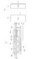
- FIG. 1 is a view schematically showing an engine exhaust system.
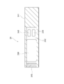
- FIG. 2 is a view schematically showing the configuration of the NOx sensor shown in FIG.
- FIG. 3 is a cross-sectional view showing a III-III cross section of FIG.
- FIG. 4 is a block diagram showing a configuration of the SCU shown in FIG.
- FIG. 5 is a block diagram showing a functional configuration of the microcomputer shown in FIG.
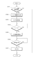
- FIG. 6 is a flowchart showing processing of the ECU and the SCU shown in FIG.
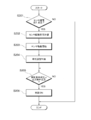
- FIG. 7 is a flowchart showing processing of the ECU and the SCU shown in FIG.
- FIG. 8 is a diagram for explaining the process of the SCU shown in FIG.
- FIG. 9 is a diagram for explaining the process of the SCU shown in FIG. FIG.
- FIG. 10 is a diagram for explaining the process of the SCU shown in FIG.
- FIG. 11 is a diagram for explaining the process of the SCU shown in FIG.
- FIG. 12 is a diagram for explaining the process of the SCU shown in FIG.
- FIG. 13 is a diagram for explaining the process of the SCU shown in FIG.
- FIG. 14 is a diagram for explaining the process of the SCU shown in FIG.
- the engine exhaust system ES is provided with an ECU (Engine Control Unit) 10 and an SCU (Sensor Control Unit) 40.
- the ECU 10 is a device that controls the diesel engine 20 and an engine exhaust system ES connected thereto.
- the ECU 10 has a function of controlling the behavior of the diesel engine 20.
- the ECU 10 adjusts the opening degree of the fuel injection valve based on the accelerator opening degree and the engine rotational speed.
- a diesel oxidation catalytic converter 22 and a selective catalytic reduction (SCR) catalytic converter 28 are provided in order from the diesel engine 20 side.
- the diesel oxidation catalytic converter 22 includes a diesel oxidation catalyst (DOC) 221 and a diesel particulate filter (DPF: diesel particulate filter) 222.
- DOC diesel oxidation catalyst
- DPF diesel particulate filter
- the diesel oxidation catalytic converter 22 purifies harmful substances contained in the exhaust gas by oxidation or reduction, and is an apparatus for collecting particulate matter (PM: Particulate Matter) made of carbon or the like.
- PM particulate Matter
- the diesel oxidation catalyst 221 is mainly composed of a ceramic carrier, an oxide mixture containing aluminum oxide, cerium dioxide and zirconium dioxide as components, and a noble metal catalyst such as platinum, palladium and rhodium.
- the diesel oxidation catalyst 221 oxidizes and purifies hydrocarbons, carbon monoxide, nitrogen oxides and the like contained in the exhaust gas.
- the diesel oxidation catalyst 221 raises the temperature of the exhaust gas by the heat generated during the catalytic reaction.
- the diesel particulate filter 222 is formed of a honeycomb structure in which a platinum group catalyst such as platinum or palladium is supported on porous ceramic.
- the diesel particulate filter 222 deposits particulate matter contained in the exhaust gas on the partition walls of the honeycomb structure.
- the deposited particulate matter is oxidized and purified by combustion. For this combustion, the temperature rise in the diesel oxidation catalyst 221 and the combustion temperature decrease of the particulate matter due to the additive are used.
- the SCR catalytic converter 28 is an apparatus for reducing NOx to nitrogen and water as an aftertreatment device for the diesel oxidation catalytic converter 22, and has an SCR 281 which is a selective reduction type catalyst.
- the SCR 281 can be exemplified by a catalyst in which a noble metal such as Pt is supported on a substrate surface such as zeolite or alumina.
- the SCR 281 reduces and purifies NOx when the catalyst temperature is in the active temperature range and urea as a reducing agent is further added.
- a urea addition injector 26 is provided upstream of the SCR catalytic converter 28 for urea addition.
- the NOx sensor 24 is disposed between the diesel oxidation catalytic converter 22 and the urea addition injector 26, and the NOx sensor 30 is disposed downstream of the SCR catalytic converter 28.
- the amount of urea to be added from the urea addition injector 26 to the SCR catalytic converter 28 is determined. More specifically, the amount of urea to be added is determined based on the NOx concentration detected from the exhaust gas before passing through the SCR catalytic converter 28 in the NOx sensor 24. Further, feedback is performed so that the NOx concentration detected from the exhaust gas after passing through the SCR catalytic converter 28 in the NOx sensor 30 becomes as small as possible, and the amount of urea to be added is corrected.
- the amount of urea thus determined is added from the urea addition injector 26 to the SCR 281, whereby the NOx in the exhaust gas is properly reduced in the SCR 281.
- hydrocarbons, carbon monoxide, and nitrogen oxides contained in the exhaust gas are externally transmitted from the tail pipe (not shown) which is the end of the engine exhaust system ES. Exhausted.
- the SCU 40 detects the current output from the NOx sensor 24 and the NOx sensor 30.
- the SCU 40 detects an amount of gas and performs abnormality detection processing, and transmits necessary data to the ECU 10.
- the ECU 10 and the SCU 40 are connected to a CAN (Controller Area Network) bus 50 and perform information communication via the CAN bus 50.
- CAN Controller Area Network
- the ECU 10 includes an arithmetic device such as a CPU, a RAM, a ROM, an input / output port, and a storage device.
- an arithmetic device such as a CPU, a RAM, a ROM, an input / output port, and a storage device.
- the function of detecting an abnormality in the electrical system connected to the NOx sensors 24 and 30 will be mainly described. Since the NOx sensor 24 and the NOx sensor 30 have the same configuration, the configuration will be described by taking the NOx sensor 24 as an example.
- the NOx sensor 24 includes a first body portion 241 a, a second body portion 241 b, a solid electrolyte body 244, a diffusion resistor 245, a pump electrode 246, and a heater 247. , A sensor electrode 248, a monitor electrode 249, and a common electrode 250.
- the solid electrolyte body 244 is a plate-like member, and is made of an oxygen ion conductive solid electrolyte material such as zirconia oxide.
- the first main body portion 241 a and the second main body portion 241 b are made of an insulator mainly composed of alumina, and are disposed with the solid electrolyte body 244 interposed therebetween.
- the first main body portion 241 a is formed with a recess provided so as to retract from the solid electrolyte body 244 side.
- the recess functions as a measurement chamber 242.
- One side of the measurement chamber 242 is open.
- a diffusion resistor 245 is disposed on the open side.
- the diffusion resistor 245 is made of a porous or porous ceramic material such as alumina. The action of the diffusion resistor 245 regulates the speed of the exhaust gas drawn into the measuring chamber 242.
- the second main body portion 241 b is also provided with a recess provided so as to retract from the solid electrolyte body 244 side.
- the recess functions as an atmosphere chamber 243.
- One side of the atmosphere chamber 243 is open. The gas drawn into the atmosphere chamber 243 from the solid electrolyte body 244 side is released to the atmosphere.
- a pump electrode 246 which is a cathode side is provided on the surface of the solid electrolyte body 244 facing the measurement chamber 242 and on the diffusion resistor 245 side.
- the pump electrode 246 is made of a Pt-Au alloy (platinum-gold alloy).
- a common electrode 250 which is an anode side with respect to the pump electrode 246 and is mainly composed of platinum is provided on the surface of the solid electrolyte body 244 facing the atmosphere chamber 243 and corresponding to the pump electrode 246. .
- the common electrode 250 is provided so that the sensor electrode 248 and the monitor electrode 249 overlap in the facing area when projected through the solid electrolyte 244.
- oxygen contained in the exhaust gas in the measurement chamber 242 contacts the cathode side pump electrode 246 and becomes oxygen ions.
- the oxygen ions flow in the solid electrolyte body 244 toward the common electrode 250 on the anode side, release charges in the common electrode 250 to become oxygen, and are discharged from the air chamber 243 to the air.
- the pump electrode 246, the common electrode 250, and the solid electrolyte 244 sandwiched between these two electrodes form a pump cell having a function of discharging oxygen ions from the measurement chamber 242 to the atmosphere chamber 243.
- a monitor electrode 249 serving as a cathode side is provided on the surface of the solid electrolyte body 244 facing the measurement chamber 242 and opposite to the diffusion resistor 245 across the pump electrode 246. The side opposite to the diffusion resistor 245 across the pump electrode 246 corresponds to the rear side of the pump electrode 246.
- a common electrode 250 which is an anode side of the monitor electrode 249 is provided on the surface of the solid electrolyte body 244 facing the atmosphere chamber 243 and at a position corresponding to the monitor electrode 249. As described above, the monitor electrode 249, the common electrode 250, and the solid electrolyte 244 sandwiched between the two electrodes form a monitor cell having a function of detecting the oxygen concentration.
- the monitor cell detects the concentration of oxygen remaining in the exhaust gas from which oxygen has been exhausted by the pump cell.
- a voltage is applied between the monitor electrode 249 and the common electrode 250, residual oxygen contained in the exhaust gas from which oxygen is exhausted by the pump cell comes in contact with the monitor electrode 249 on the cathode side to become oxygen ions.
- the oxygen ions flow in the solid electrolyte body 244 toward the common electrode 250 on the anode side, release charges in the common electrode 250 to become oxygen, and are discharged from the air chamber 243 to the air.
- the charge at this time is detected as the monitor cell current Im by the monitor cell detection unit 404, and the residual oxygen concentration in the exhaust gas can be calculated based on the monitor cell current Im.
- a sensor electrode 248 which is a cathode side is provided on the surface of the solid electrolyte body 244 facing the measurement chamber 242 and opposite to the diffusion resistor 245 with the pump electrode 246 interposed therebetween.
- a common electrode 250 which is an anode side of the sensor electrode 248 is provided at a position corresponding to the sensor electrode 248, which is a surface of the solid electrolyte body 244 facing the atmosphere chamber 243.
- the sensor electrode 248 is made of a Pt-Rh alloy (platinum-rhodium alloy) and has a strong reducibility against NOx.
- the NOx in contact with the sensor electrode 248 is reductively decomposed into N2 and O2.
- the decomposed O 2 receives a charge from the sensor electrode 248 on the cathode side to become oxygen ions.
- the oxygen ions flow in the solid electrolyte body 244 toward the common electrode 250 on the anode side, release charges in the common electrode 250 to become oxygen, and are discharged from the air chamber 243 to the air.
- the charge at this time is detected as the sensor cell current Is by the sensor cell detection unit 403, and the concentration of NOx in the exhaust gas and the residual oxygen concentration can be calculated based on the sensor cell current Is.
- the pump cell can detect the output depending on the oxygen concentration in the exhaust gas
- the function of the A / F sensor can also be provided.
- the element temperature is calculated by the output current when a predetermined voltage is applied.
- the element temperature has a correlation with the resistance of the element, but since the element has a capacitive component, it is preferable to remove the influence of the capacitive component. Therefore, it is preferable to set the applied voltage as a sweep voltage of a predetermined frequency. By applying the sweep voltage, the charge accumulated in the capacitive component of the element can be removed.
- the application of the sweep voltage has an effect of superimposing the current raised by the sweep on the output current depending on the original gas concentration, so that the gas concentration is not detected in the application period of the sweep voltage or for a predetermined time. desirable.
- the output current may be any element current. Since the current flowing by the sweep voltage is larger than the current flowing through the sensor electrode 248 and the monitor electrode 249 when detecting the gas concentration, it is preferable to grasp the element temperature by the output current of the pump electrode 246.
- the heater 247 is supplied with a voltage to the SCU 40 to start the micro-energization mode when it can be driven.
- the fine current conduction mode By setting the fine current conduction mode, it is possible to avoid sudden pressure change due to internal water boiling and breakage of the element due to water condensation on the exhaust pipe on the vehicle side being wetted by the sensor.
- the temperature is raised to a temperature at which the gas concentration can be detected, so that high-duty activation is performed early.
- the SCU 40 is configured as a digital processor with part or all of an analog circuit or a memory. In any case, in order to perform the function of outputting a control signal based on the received electrical signal, the SCU 40 is configured with a functional control block.
- FIG. 4 shows the SCU 40 as such a functional control block diagram.
- the SCU 40 includes a heater control unit 401, a pump cell detection unit 402, a sensor cell detection unit 403, a monitor cell detection unit 404, a common electrode detection unit 405, a microcomputer 406, a power supply circuit 407, a CAN communication unit 408, and a voltage. And an application circuit 409.
- the heater control unit 401 is a part that controls the voltage applied to the heater 247 and controls the amount of heat generation of the heater 247.
- the pump cell detection unit 402 is a portion that detects a pump cell current Ip flowing to the pump electrode 246.
- the pump cell detection unit 402 outputs a signal indicating the detected pump cell current Ip to the microcomputer 406.
- the pump cell detection unit 402 can also detect a pump cell voltage Vp of the pump cell.
- the pump cell detection unit 402 outputs a signal indicating the detected pump cell voltage Vp to the microcomputer 406.
- the sensor cell detection unit 403 is a portion that detects a sensor cell current Is flowing to the sensor electrode 248.
- the sensor cell detection unit 403 outputs a signal indicating the detected sensor cell current Is to the microcomputer 406.
- the monitor cell detection unit 404 is a part that detects a monitor cell current Im flowing to the monitor electrode 249.
- the monitor cell detection unit 404 outputs a signal indicating the detected monitor cell current Im to the microcomputer 406.
- the common electrode detection unit 405 is a portion that detects the common electrode current Icom flowing to the common electrode 250.
- the common electrode detection unit 405 outputs a signal indicating the detected common electrode current Icom to the microcomputer 406.
- the common electrode detection unit 405 can also detect the common electrode voltage Vcom of the common electrode 250.
- the common electrode detection unit 405 outputs a signal indicating the detected common electrode voltage Vcom to the microcomputer 406.
- the microcomputer 406 is a control unit in the SCU 40.
- the microcomputer 406 outputs a control signal for controlling the temperature of the heater 247 to the heater control unit 401.
- the microcomputer 406 is a part that calculates the NOx concentration in the exhaust gas based on the sensor cell current Is detected by the sensor cell detection unit 403 and the monitor cell current Im detected by the monitor cell detection unit 404.
- the microcomputer 406 subtracts the monitor cell current Im, which is the output current of the monitor electrode 249, from the sensor cell current Is, which is the output current of the sensor electrode 248, to remove the current value due to the residual oxygen concentration in the exhaust gas emitted by the sensor cell. Calculate the NOx concentration in the exhaust gas.
- the microcomputer 406 outputs a signal indicating the calculated NOx concentration to the CAN communication unit 408.
- the power supply circuit 407 is a power supply circuit in the SCU 40.
- the CAN communication unit 408 transmits a signal output from the microcomputer 406 to the CAN bus 50, and outputs a signal received from the CAN bus 50 to the microcomputer 406.
- the voltage application circuit 409 is a circuit unit for applying a voltage to the common electrode 250 and the pump electrode 246.
- the voltage application circuit 409 applies, to the common electrode 250, a sweep voltage in which the voltage changes continuously.
- the voltage application circuit 409 can apply a voltage to the pump electrode 246, and the voltage is variable. Further, the voltage application circuit 409 may be a composite circuit combined with another detection function (current detection or voltage detection).
- the microcomputer 406 includes, as functional components, a temperature rise determination unit 406a, an activity determination unit 406b, a time setting unit 406c, and an early activation unit 406d.
- step S101 the ECU 10 determines that the sensor energization condition is satisfied.
- the sensor energization condition is determined based on whether the environment of the NOx sensor 24 which is an exhaust gas sensor satisfies the drying condition. If the sensor energization condition is satisfied, the process proceeds to the process of step S102. If the sensor energization condition is not satisfied, the process ends.
- step S102 the sensor driving permission is transmitted from the ECU 10 to the SCU 40.
- step S103 the SCU 40 energizes the NOx sensor 24, and sensor driving is started.
- step S104 it is determined whether the pump cell admittance Ap exceeds the activity determination admittance Tha. If the pump cell admittance Ap exceeds the activity determination admittance Tha, the process proceeds to the process of step S105. If the pump cell admittance Ap does not exceed the activity determination admittance Tha, the determination of step S104 is repeated.
- step S105 the water evaporation time is calculated.
- the water evaporation time is calculated based on the time from when the sensor drive is started until the pump cell admittance Ap exceeds the activity determination admittance Tha.
- step S106 it is determined whether a time condition is satisfied.
- the establishment of the time condition is to ensure a time during which the influence of the water vapor and / or the rich gas on the sensor cell and the monitor cell which are the second cell is eliminated after the temperature rising condition is established. If the activity determination admittance Tha for setting the temperature rising condition is set low, the time for eliminating the influence of the water vapor and / or the rich gas becomes long, so the setting time for the time condition establishment becomes long. If the activity determination admittance Tha for setting the temperature rising condition is set high, the time for eliminating the influence of water vapor and / or rich gas becomes short, so the setting time for the time condition establishment becomes short, depending on the case. May be zero.
- the time condition under the operating condition where the time for which the water vapor and / or the rich gas disappear is the longest is set.
- the elapsed time from the sensor driving in step S103 to the establishment of the temperature rise condition in step S104 or the elapse of the threshold time variable according to the sensor environment can be regarded as the establishment of the time condition.
- the evaporation time of the water vapor and / or the rich gas becomes longer.
- the flow velocity of the portion where the NOx sensor 24 is disposed becomes slower, the evaporation time of the water vapor and / or the rich gas becomes longer.
- the threshold time can be determined according to such a situation. Further, the evaporation time corresponding to the minimum flow velocity of the mounted vehicle may be set as the threshold time.
- the evaporation time of the water vapor and / or the rich gas can also be set from the relationship between the rotational speed and the load. For example, in the idle condition, it is set to 50 s.
- step S106 If the time condition is not satisfied in step S106, the determination in step S106 is repeated. If the time condition is satisfied in step S106, the process proceeds to step S107. In step S107, the sensor activation determination is ON for water vapor and / or rich gas.
- step S201 the ECU 10 determines that the sensor energization condition is satisfied.
- the sensor energization condition is determined based on whether the environment of the NOx sensor 24 which is an exhaust gas sensor satisfies the drying condition. If the sensor energization condition is satisfied, the process proceeds to the process of step S202. If the sensor energization condition is not satisfied, the process ends.
- step S202 the sensor drive permission is transmitted from the ECU 10 to the SCU 40.
- step S203 following step S202 the SCU 40 energizes the NOx sensor 24, and sensor driving is started.
- step S204 following step S203 early activation control is executed. Specifically, the voltage applied to the pump cell is temporarily raised.
- step S205 it is determined whether an activation control time condition is established. Instead of the activation control time condition, it may be determined whether an output condition is satisfied.
- the establishment of the activation control time condition is conditioned on the passage of time for eliminating the influence of hydrogen generated due to the early activation control.
- the establishment of the output condition is on the condition that the output of the monitor cell has a substantially positive value.
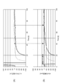
- (A) shows the current of the monitor cell
- (B) shows the detected NOx concentration.
- the solid line shows an example of the NOx sensor whose hydrogen elimination is slow
- the broken line shows the example of the NOx sensor whose hydrogen elimination is early.
- the detected NOx concentration is close to the actual gas concentration from the vicinity where the value of the monitor cell current exceeds zero. Therefore, on the condition that the output of the monitor cell has a substantially positive value, it can be determined that the influence of the residual hydrogen is eliminated.
- the monitor cell current value may fluctuate, not only when the monitor cell current value instantaneously becomes positive but also when the monitor cell current value becomes positive several times continuously or intermittently. It is preferable to judge that the influence of residual hydrogen is eliminated.
- the threshold may be slightly offset to the negative side (about several nA).
- step S205 if the activation control time condition or the output condition is not satisfied, the determination in step S205 is repeated.
- step S106 when the activation control time condition or the output time condition is satisfied, the process proceeds to step S206.
- step S206 the sensor activation determination is ON for hydrogen.
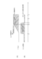
- FIG. 8 shows the establishment of the temperature condition described with reference to FIG. 6 and the establishment of the time condition of water vapor / rich gas evaporation.
- FIG. 8B shows the establishment of the time condition for hydrogen annihilation described with reference to FIG.
- the time t1 in (A) of FIG. 8 is the processing timing of step S102 of FIG.
- Time t2 in (A) of FIG. 8 is the processing timing of step S104 of FIG.
- Time t4 in (A) of FIG. 8 is processing timing of step S106 of FIG.
- Time t1 in (B) of FIG. 8 is processing timing of steps S203 and S204 of FIG.
- Time t3 in (B) of FIG. 8 is timing when the process of step 204 of FIG. 7 ends.
- Time t5 in (B) of FIG. 8 is processing timing of step S205 of FIG.
- the early activation control when the early activation control is not performed, it can be determined that the activation of the NOx sensor 24 is completed, with the establishment of the temperature condition and the establishment of the time condition of water vapor / rich gas evaporation described with reference to FIG.
- the abnormality determination of the NOx sensor 24 can be performed using the satisfaction of the temperature condition described with reference to FIG.
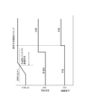
- the NOx sensor 24 is normal, as shown in FIG. 13, since the abnormality determination start timing comes after the establishment of the temperature condition and the time condition of water vapor / rich gas evaporation, the activation abnormality flag is transitioned from indeterminate to normal. .
- the microcomputer 406 is a control device of the NOx sensor 24 which is an exhaust gas sensor, and is a first cell indicating a temperature of a pump cell which is a first cell for removing oxygen from exhaust gas discharged from the internal combustion engine 20.
- the parameter and the second parameter indicating the temperature of the sensor cell and the monitor cell which are the second cell for detecting the measurement target component contained in the measurement target gas from which the oxygen has been removed by the operation of the pump cell which is the first cell
- a temperature determination unit 406a and an activity determination unit 406b that determines whether the NOx sensor 24 is in an active state that can be measured while securing predetermined accuracy are provided.
- the temperature rise determination unit 406a determines whether the temperature rise conditions for the first cell and the second cell are satisfied, based on whether at least one of the first parameter and the second parameter exceeds a predetermined temperature threshold, and the activity determination unit 406b After the temperature raising condition is established, when the time condition corresponding to the temperature threshold is satisfied, it is determined that the NOx sensor 24 is in the activated state.
- the temperature raising condition When the temperature raising condition is satisfied, it can be determined that the first cell or the second cell constituting the NOx sensor 24 which is the exhaust gas sensor satisfies the necessary condition of the active state.
- the establishment of the time condition it is also possible to determine the concentration decrease of the gas that becomes the inhibiting factor to secure the detection accuracy in the NOx sensor 24, so the activity determination with higher accuracy It can be performed. Since the establishment of the time condition is determined corresponding to the temperature threshold value for determining the establishment of the temperature rising condition of the first cell and the second cell, when the temperature threshold value is set high or low Even in this case, it is possible to determine the decrease in the concentration of the inhibiting gas according to the set value.
- the time condition is set so as to ensure a time during which the influence of water vapor and / or rich gas on the second cell is eliminated after the temperature raising condition is satisfied.
- the time condition is set so as to ensure the time during which the influence of water vapor and / or rich gas on the second cell is eliminated after the temperature rising condition is satisfied, the influence of water vapor and / or rich gas as an inhibiting gas is It is possible to make sure that the determination is made and the activity determination can be performed with higher accuracy.
- At least one of the first parameter and the second parameter is an admittance or an impedance when an alternating voltage is applied. Since the admittance or impedance at the time of AC voltage application is used as the parameter used for the temperature rise determination, the temperature rise determination can be performed accurately.
- the time setting unit 406 c is further provided which sets a predetermined time for determining the establishment of the time condition, and the time setting unit 406 c starts to energize the first cell and the second cell.
- the predetermined time is set based on the time until the temperature rise condition is established.
- the time from the start of energization of the first cell and the second cell to the establishment of the temperature rising condition varies depending on the reaction capacity of the cell, so setting the predetermined time according to this time Judgment of establishment can be optimized.
- the time setting unit 406 c is further provided to set a predetermined time for determining the establishment of the time condition, and the time setting unit 406 c operates the environment where the NOx sensor 24 is provided or the operation of the internal combustion engine 20.
- the predetermined time is set based on the conditions.
- the time condition according to the environment and operating conditions can be set by setting the predetermined time in consideration of these. It becomes possible to set
- the early activation unit 406d is further provided which executes early activation control to temporarily increase the voltage applied to the first cell when the internal combustion engine 20 is started.
- the early activation unit 406d determines an early activation completion condition for completing early activation control. In the case where the temperature determination condition, the time condition, and the early activation completion condition are satisfied, and the activity control time condition for eliminating the influence of hydrogen generated due to the early activation control is satisfied.
- the exhaust gas sensor is determined to be in an active state. Since the early activation control enables determination of the activation state in consideration of the influence of hydrogen generated, early activation judgment can be performed by utilizing the effect of the early activation.
- the NOx sensor 24 includes, as the second cell, a monitor cell for detecting the concentration of oxygen contained in the gas to be measured from which the oxygen has been removed by the operation of the first cell. 406b determines that the NOx sensor 24 is in the activated state if the output of the monitor cell indicates that the influence of hydrogen is removed instead of the establishment of the activation control time condition after the temperature rise condition is established. Since the monitor cell can confirm that the influence of hydrogen has been eliminated, it is possible to judge the activation state earlier and with higher accuracy.
- the activity determining unit 406b determines that the NOx sensor 24 is abnormal. Since the abnormality of the NOx sensor 24 can be determined by not satisfying the conditions within the predetermined time, the abnormality determination can be performed without spending unnecessary time.
- the temperature rise condition is determined based on whether at least one of the first parameter and the second parameter indicates that the admittance or impedance at the time of application of the alternating voltage exceeds a predetermined threshold value.
- the method of determining the temperature rise condition is not limited to this.
- each threshold corresponding to the first parameter and the second parameter is set in advance, and the temperature rise condition is determined based on whether each of the first parameter and the second parameter exceeds the set threshold. You may configure. According to this, since the temperature rise determination is performed based on both the first parameter and the second parameter, it is possible to reliably determine the active state.
- the NOx sensor 24 is disposed between the diesel oxidation catalytic converter 22 and the urea addition injector 26, and the NOx sensor 30 is disposed downstream of the SCR catalytic converter 28.
- An NOx storage reduction catalyst LNT Lean NOx Trap
- LNT Lean NOx Trap
- the LNT is composed of a NOx storage material and a ceramic carrier. LNT temporarily occludes NOx in exhaust gas into a NOx storage material consisting of an alkali metal such as potassium or an alkaline earth metal such as barium when the engine state is lean, to make the engine state rich
- the HC is supplied into the exhaust gas to release the stored NOx. Then, the released NOx is reduced by the function of the SCR catalytic converter provided downstream.
- the NOx sensor can be further provided upstream of the LNT. That is, the NOx sensor can be provided on the upstream side of the NOx storage reduction catalyst, between the diesel oxidation catalytic converter 22 and the urea addition injector 26, and on the downstream side of the SCR catalytic converter 28, respectively. And each NOx sensor is connected to one SCU. Others are the same as the said embodiment.
- the state of the engine can be switched to rich or lean on the ECU 10 side.
- the NOx sensor on the upstream side of the LNT contains a large amount of other gases because the exhaust gas discharged from the engine often does not pass through the reduction catalyst etc., and the influence of the other gases is large when detecting the NOx sensor. Therefore, in the activity determination of the NOx sensor on the upstream side of LNT, it is necessary to set a long time during which the influence of water vapor and / or rich gas on the sensor cell and monitor cell is eliminated after the temperature rising condition is satisfied corresponding to step S105. There is.
- the time condition is preferably set longer than the NOx sensor provided downstream of the LNT.
- the time during which the influence of water vapor and / or rich gas is eliminated becomes longer than the NOx sensor provided on the downstream side of LNT, so the influence of gas which is an inhibiting factor to secure the detection accuracy of the NOz sensor is taken into consideration.
- the activity of the NOx sensor can be determined accurately.
- the NOx sensor provided upstream of the LNT in the first modification can be provided between the LNT and the diesel oxidation catalytic converter.
- the NOx sensor can be provided between the LNT and the diesel oxidation catalytic converter, between the diesel oxidation catalytic converter 22 and the urea addition injector 26, and downstream of the SCR catalytic converter 28, respectively.
- the NOx sensor is a gas whose exhaust gas does not pass through a reduction catalyst or the like, so the influence of other gases is also large. Therefore, as in the first modification, the first parameter or the second parameter is the determination with respect to the activity determination admittance Tha for establishing the temperature rising condition in the NOx sensor provided between the LNT and the diesel oxidation catalytic converter
- the time condition from exceeding the admittance Tha of to the activation judgment ON is set longer than the NOx sensor provided between the diesel oxidation catalytic converter 22 and the urea addition injector 26 or downstream of the SCR catalytic converter 28. Is preferred.
- the time during which the influence of water vapor and / or rich gas is eliminated is longer than the NOx sensor provided between the diesel oxidation catalytic converter 22 and the urea addition injector 26 or downstream of the SCR catalytic converter 28.
- the activity of the NOx sensor can be determined with high accuracy, taking into consideration the influence of gas, which is an inhibiting factor for securing the detection accuracy of the NOz sensor.
Landscapes
- Engineering & Computer Science (AREA)
- Chemical & Material Sciences (AREA)
- General Engineering & Computer Science (AREA)
- Mechanical Engineering (AREA)
- Combustion & Propulsion (AREA)
- Chemical Kinetics & Catalysis (AREA)
- Health & Medical Sciences (AREA)
- Life Sciences & Earth Sciences (AREA)
- Biochemistry (AREA)
- General Health & Medical Sciences (AREA)
- General Physics & Mathematics (AREA)
- Immunology (AREA)
- Pathology (AREA)
- Analytical Chemistry (AREA)
- Physics & Mathematics (AREA)
- Electrochemistry (AREA)
- Molecular Biology (AREA)
- Exhaust Gas After Treatment (AREA)
- Combined Controls Of Internal Combustion Engines (AREA)
Abstract
第1パラメータが予め定められた第1閾値を超えたか、又は第2パラメータが予め定められた第2閾値を超えたかの一方の条件成立によって、第1セル又は第2セルの昇温条件成立を判断し、昇温条件成立後、対応する時間条件が成立している場合に、排出ガスセンサが活性状態になっていると判断する。
Description
本出願は、2017年9月29日に出願された日本国特許出願2017-190369号に基づくものであって、その優先権の利益を主張するものであり、その特許出願の全ての内容が、参照により本明細書に組み込まれる。
本開示は、排出ガスセンサの制御装置に関する。
内燃機関から排出される排出ガスに含まれる成分を検出する排出ガスセンサは、駆動開始から所定の条件を満たすと活性状態となり、検出誤差が所定範囲内の検出データを出力することができる。そのため、例えば下記特許文献1のように、排出ガスセンサの活性化判定を行うものが知られている。
特許文献1では、排出ガスセンサを構成するセルの素子温を表すパラメータに基づいて、排出ガスセンサの活性化がなされたか否かを判断している。しかしながら、温度条件のみでは、排出ガスセンサ内の状況が一義的に把握できないため、例えば検出データの正確性を阻害するガス成分が残った状態であることも想定される。
本開示は、温度条件のみならずセンサ内部の状況も勘案して排出ガスセンサの活性化を判断することが可能な制御装置を提供することを目的とする。
本開示は、排出ガスセンサの制御装置であって、内燃機関から排出される排気ガスから酸素を除去するための第1セルの温度を示す第1パラメータ、又は第1セルの作動により酸素が除去された測定対象ガスに含まれる測定対象成分を検出するための第2セルの温度を示す第2パラメータを取得する昇温判定部と、排出ガスセンサが、所定の精度を確保し測定可能な活性状態になったか否かを判断する活性判定部と、を備えている。昇温判定部は、第1パラメータ又は第2パラメータが予め定められた温度閾値を超えたかによって、第1セル及び第2セルの昇温条件成立を判断し、活性判定部は、昇温条件成立後、温度閾値に対応する時間条件が成立している場合に、排出ガスセンサが活性状態になっていると判断する。
昇温条件成立によって、排出ガスセンサを構成する第1セル又は第2セルが活性状態の必要条件を満たしていると判断することができる。この昇温条件に加えて、時間条件の成立を判断することで、排出ガスセンサ内において検出精度を確保する阻害要因となるガスの濃度低下も判断することができるので、より精度の高い活性判定を行うことができる。時間条件の成立は、第1セル又は第2セルの昇温条件成立を判断するための温度閾値に対応して判断するようにしているので、温度閾値が高く設定されたり低く設定されたりした場合であっても、その設定値に応じた阻害要因ガスの濃度低下を判断することができる。
以下、添付図面を参照しながら本実施形態について説明する。説明の理解を容易にするため、各図面において同一の構成要素に対しては可能な限り同一の符号を付して、重複する説明は省略する。
図1に示されるように、エンジン排気系ESには、ECU(Engine Control Unit)10及びSCU(Sensor Control Unit)40が設けられている。ECU10は、ディーゼルエンジン20及びそれに繋がるエンジン排気系ESを制御する装置である。ECU10は、ディーゼルエンジン20の挙動を制御する機能を有している。ECU10は、アクセル開度及びエンジン回転速度に基づいて燃料噴射弁の開度を調整する。
エンジン排気系ESには、ディーゼルエンジン20側から順に、ディーゼル酸化触媒コンバータ22と、SCR(Selective Catalytic Reduction)触媒コンバータ28と、が設けられている。ディーゼル酸化触媒コンバータ22は、ディーゼル酸化触媒(DOC:Diesel Oxidation Catalyst)221と、ディーゼルパティキュレートフィルタ(DPF:Diesel Particulate Filter)222と、を有している。
ディーゼル酸化触媒コンバータ22は、排出ガスに含まれる有害物質を酸化又は還元により浄化するものであって、特に炭素などからなる粒子状物質(PM:Particulate Matter)を捕集する装置である。
ディーゼル酸化触媒221は、主としてセラミック製の担体と、酸化アルミニウム、二酸化セリウム及び二酸化ジルコニウムを成分とする酸化物混合物、並びに白金、パラジウム、ロジウムといった貴金属触媒で構成されている。ディーゼル酸化触媒221は、排出ガスに含まれる炭化水素、一酸化炭素、窒素酸化物などを酸化させ浄化する。また、ディーゼル酸化触媒221は、触媒反応の際に発生する熱により排出ガス温度を上昇させる。
ディーゼルパティキュレートフィルタ222は、多孔質セラミックに白金やパラジウムなどの白金族触媒が担持され、ハニカム構造体で形成される。ディーゼルパティキュレートフィルタ222は、排出ガス中に含まれる粒子状物質をハニカム構造体の隔壁に堆積させる。堆積した粒子状物質は、燃焼によって酸化され浄化される。この燃焼には、ディーゼル酸化触媒221における温度上昇や、添加剤による粒子状物質の燃焼温度低下が利用される。
SCR触媒コンバータ28は、ディーゼル酸化触媒コンバータ22の後処理装置としてNOxを窒素と水に還元する装置であって、選択還元型の触媒であるSCR281を有する。SCR281は、ゼオライト又はアルミナなどの基材表面にPtなどの貴金属を担持した触媒が例示できる。SCR281は、触媒温度が活性温度域にあり、さらに、還元剤としての尿素が添加されているときにNOxを還元浄化するものである。尿素添加のため、SCR触媒コンバータ28の上流側には、尿素添加インジェクタ26が設けられている。
本実施形態では、ディーゼル酸化触媒コンバータ22と尿素添加インジェクタ26との間にNOxセンサ24が、SCR触媒コンバータ28の下流側にNOxセンサ30がそれぞれ配置されている。
NOxセンサ24で検出されるNOx濃度と、NOxセンサ30で検出されるNOx濃度とに基づき尿素添加インジェクタ26からSCR触媒コンバータ28に対して添加される尿素の量が決定される。より具体的には、NOxセンサ24においてSCR触媒コンバータ28通過前の排出ガスから検出されるNOx濃度に基づいて添加する尿素の量が決定される。また、NOxセンサ30においてSCR触媒コンバータ28を通過した後の排出ガスから検出されるNOx濃度が極力小さい値となるようにフィードバックし、添加する尿素の量を補正する。このように決定された量の尿素が、尿素添加インジェクタ26からSCR281に対して添加されることで、SCR281において排出ガス中のNOxが適正に還元される。このように、排出ガスに含まれる炭化水素、一酸化炭素、窒素酸化物は、NOxセンサ24及びNOxセンサ30を通過した後、エンジン排気系ESの終端であるテールパイプ(不図示)から外部に排出される。
NOxセンサ24及びNOxセンサ30が出力する電流は、SCU40が検出している。SCU40は、ガス量を検出すると共に異常検出処理を行って、必要なデータをECU10に送信している。ECU10及びSCU40は、CAN(Controller Area Network)バス50に繋がっており、CANバス50を介して情報通信を行っている。
ECU10は、CPU等の演算装置、RAM、ROM、入出力ポート、及び記憶装置を含むものである。特に本実施形態の説明では、NOxセンサ24,30に繋がる電気系統の異常を検出する機能を中心に説明をする。NOxセンサ24とNOxセンサ30とは同一の構成であるため、NOxセンサ24を例にとってその構成を説明する。
図2及び図3に示されるように、NOxセンサ24は、第1本体部241aと、第2本体部241bと、固体電解質体244と、拡散抵抗体245と、ポンプ電極246と、ヒータ247と、センサ電極248と、モニタ電極249と、共通電極250と、を備えている。
固体電解質体244は板状の部材であって、酸化ジルコニア等の酸素イオン伝導性固体電解質材料によって構成されている。第1本体部241a及び第2本体部241bは、アルミナを主成分とする絶縁体からなり、固体電解質体244を挟んで配置されている。第1本体部241aには、固体電解質体244側から後退するように設けられた凹部が形成されている。その凹部は測定室242として機能している。測定室242の一側面は開放されている。その開放された一側面に拡散抵抗体245が配置されている。拡散抵抗体245は、多孔質又は細孔が形成されたアルミナ等のセラミック材料からなっている。拡散抵抗体245の作用により、測定室242内に引き込まれる排出ガスの速度が律せられる。
第2本体部241bにも、固体電解質体244側から後退するように設けられた凹部が形成されている。その凹部は大気室243として機能している。大気室243の一側面は開放されている。固体電解質体244側から大気室243内に引き込まれる気体は大気に放出される。
固体電解質体244の測定室242側に臨む面であって、拡散抵抗体245側には陰極側となるポンプ電極246が設けられている。ポンプ電極246は、Pt-Au合金(白金-金合金)からなる。また、固体電解質体244の大気室243に臨む面であって、ポンプ電極246と対応する位置には、ポンプ電極246に対して陽極側となり主成分がプラチナからなる共通電極250が設けられている。共通電極250は、センサ電極248及びモニタ電極249が固体電解質244を介して投影した際の対向領域において重なるように設けられている。
ポンプ電極246と共通電極250との間に電圧が印加されると、測定室242内の排出ガス中に含まれる酸素が陰極側のポンプ電極246に接触して酸素イオンとなる。この酸素イオンは、陽極側の共通電極250に向かって固体電解質体244内を流れ、共通電極250において電荷を放出して酸素となり、大気室243から大気中に排出される。このように、ポンプ電極246、共通電極250、及びこれら2つの電極に挟まれる固体電解質244によって、酸素イオンを測定室242から大気室243に排出する機能を有するポンプセルが形成されている。
なお、ポンプ電極246と共通電極250との間に印加する電圧が高いほど、ポンプセルによって排出ガス中から大気室243を経由して大気中に排出される酸素の量は多くなる。逆にポンプ電極246と共通電極250との間に印加する電圧が低いほど、ポンプセルによって排出ガス中から排出される酸素の量は減る。従って、ポンプ電極246と共通電極250との間に印加する電圧を増減することで、後段のセンサ電極248及びモニタ電極249に流れる排出ガス中の残留酸素の量を増減させることができる。
固体電解質体244の測定室242側に臨む面であって、ポンプ電極246を挟んで拡散抵抗体245とは反対側には陰極側となるモニタ電極249が設けられている。ポンプ電極246を挟んで拡散抵抗体245とは反対側は、ポンプ電極246よりも後段側に相当する。固体電解質体244の大気室243に臨む面であって、モニタ電極249と対応する位置にモニタ電極249に対して陽極側となる共通電極250が設けられている。このように、モニタ電極249、共通電極250、及びこれら2つの電極に挟まれる固体電解質244によって、酸素濃度を検出する機能を有するモニタセルが形成されている。
モニタセルは、ポンプセルによって酸素が排出された排出ガス中に残留する酸素濃度を検出する。モニタ電極249と共通電極250との間に電圧が印加されると、ポンプセルによって酸素が排出された排出ガス中に含まれる残留酸素が陰極側のモニタ電極249に接触して酸素イオンとなる。この酸素イオンは、陽極側の共通電極250に向かって固体電解質体244内を流れ、共通電極250において電荷を放出して酸素となり、大気室243から大気中に排出される。この際の電荷は、モニタセル検出部404によりモニタセル電流Imとして検出され、このモニタセル電流Imに基づいて、排出ガス中の残留酸素濃度を算出し得る。
固体電解質体244の測定室242側に臨む面であって、ポンプ電極246を挟んで拡散抵抗体245とは反対側には陰極側となるセンサ電極248が設けられている。固体電解質体244の大気室243に臨む面であって、センサ電極248と対応する位置にセンサ電極248に対して陽極側となる共通電極250が設けられている。このように、センサ電極248、共通電極250、及びこれら2つの電極に挟まれる固体電解質244によって、排出ガス中のNOxの濃度及び残留酸素濃度を算出するセンサセルが形成されている。
センサ電極248は、Pt-Rh合金(白金-ロジウム合金)からなり、NOxに対して強い還元性を有している。センサ電極248に接触したNOxは、N2とO2とに還元分解される。センサ電極248と共通電極250との間に電圧が印加されると、分解されたO2は、陰極側のセンサ電極248から電荷を受け取って酸素イオンとなる。この酸素イオンは、陽極側の共通電極250に向かって固体電解質体244内を流れ、共通電極250において電荷を放出して酸素となり、大気室243から大気中に排出される。この際の電荷は、センサセル検出部403によりセンサセル電流Isとして検出され、このセンサセル電流Isに基づいて、排出ガス中のNOxの濃度及び残留酸素濃度を算出し得る。
ポンプセルで排出する酸素によって、測定室242内に流入する絶対ガス量が変化するため、NOx濃度の算出にあたっては、ポンプセルの影響を補正することが好ましい。
また、ポンプセルにおいて、排出ガス内の酸素濃度に依存した出力を検出することができるため、A/Fセンサの機能ももたせることができる。A/Fの算出にあたっては、ポンプ電極246と共通電極250との間を流れる電流であるポンプセル電流Ipにて算出することが好ましい。これらガス濃度検知は、車両で使われ方を考慮し、例えば5ms毎に行うことができる。
ガス濃度検知のためには、酸素イオンを流すため、素子温度が所定温度となるようにヒータ247で加温する必要がある。素子温度を把握することが必要であるが、直接温度を検知するセンサは装備していないため、所定の電圧を印加した場合の出力電流によって素子温度を算出する。素子温度は素子の抵抗と相関性があるが、素子には容量成分があるため、容量成分の影響を除去することが好ましい。そのため、印加電圧を所定周波数の掃引電圧とすることが好ましい。掃引電圧を印加することで、素子の容量成分に溜まった電荷を抜くことができる。掃引電圧の印加は、本来のガス濃度に依存した出力電流に掃引によって隆起された電流も重畳させる影響を及ぼすため、掃引電圧の印加期間もしくは、所定時間においてはガス濃度の検出を行わないことが望ましい。また、共通電極の電圧を掃引電圧とすることにより、ポンプ電極246、センサ電極248、モニタ電極249の各々の電流が流れる為、素子温度としてはどの出力電流としても良い。ガス濃度を検知する際にセンサ電極248やモニタ電極249を流れる電流に対して、掃引電圧によって流れる電流は大きくなるため、ポンプ電極246の出力電流によって素子温度を把握することが好ましい。
ヒータ247には、素子の破壊を防ぐため、SCU40に電圧が供給され駆動できる状態になった段階で微通電モードを開始する。微通電モードとすることで、内部水分の沸騰による圧力急変や車両側の排気管の凝縮水がセンサに被水し素子が破壊することを避けることができる。その後、ECU10からの通電要求を受け取ると、ガス濃度検知ができる温度に昇温するため、高デューティで早期活性させる。また、素子が破壊されたことやセンサの異常(断線、ショート等)をトリガとして、ヒータ247への通電を強制カットする機能を備えることも好ましい。SCU40の電源電圧によって素子の活性度合いが変化することを防止するため、SCU40の認識した電圧によってヒータ247のデューティを変化させることも好ましい。
一方、ヒータ247へ通電し、ポンプセル、及びセンサセルが機能する温度条件まで昇温させた後には、上述したようにポンプセルにより酸素を測定室242から大気室243へ排出するために電圧を印加する。ここで、エンジン始動時ではセンサ電極248の表面が酸化している可能性があり、このセンサ電極248の表面に含まれる酸素の影響によりセンサセルにおいて電流が流れてしまう可能性がある。これにより、エンジン始動時にはNOx濃度を精度良く検出することができない可能性がある。そこで、通常時よりも一時的に高い電圧をポンプセルに印加することで、測定室内のガスに含まれる水蒸気等の水分から電気分解により水素を生成させ、センサ電極248の表面に含まれる酸素を強制的に還元させることが望ましい。以降、ポンプセルにこの一時的な電圧を印加する制御を早期活性制御と呼称する。
SCU40は、その一部又は全部が、アナログ回路で構成されるか、メモリを備えたデジタルプロセッサとして構成される。いずれにしても、受信した電気信号に基づいて制御信号を出力する機能を果たすため、SCU40には機能的な制御ブロックが構成される。図4は、SCU40を、このような機能的な制御ブロック図として示したものである。
続いて、SCU40の機能的な構成要素について説明する。SCU40は、ヒータ制御部401と、ポンプセル検出部402と、センサセル検出部403と、モニタセル検出部404と、共通電極検出部405と、マイコン406と、電源回路407と、CAN通信部408と、電圧印加回路409と、を備えている。
ヒータ制御部401は、ヒータ247に印加する電圧を制御し、ヒータ247の発熱量を制御する部分である。
ポンプセル検出部402は、ポンプ電極246に流れるポンプセル電流Ipを検出する部分である。ポンプセル検出部402は、検出したポンプセル電流Ipを示す信号をマイコン406に出力する。ポンプセル検出部402は、ポンプセルのポンプセル電圧Vpも検出することができる。ポンプセル検出部402は、検出したポンプセル電圧Vpを示す信号をマイコン406に出力する。
センサセル検出部403は、センサ電極248に流れるセンサセル電流Isを検出する部分である。センサセル検出部403は、検出したセンサセル電流Isを示す信号をマイコン406に出力する。
モニタセル検出部404は、モニタ電極249に流れるモニタセル電流Imを検出する部分である。モニタセル検出部404は、検出したモニタセル電流Imを示す信号をマイコン406に出力する。
共通電極検出部405は、共通電極250に流れる共通電極電流Icomを検出する部分である。共通電極検出部405は、検出した共通電極電流Icomを示す信号をマイコン406に出力する。共通電極検出部405は、共通電極250の共通電極電圧Vcomも検出することができる。共通電極検出部405は、検出した共通電極電圧Vcomを示す信号をマイコン406に出力する。
マイコン406は、SCU40内の制御部である。マイコン406は、ヒータ制御部401にヒータ247の温度を制御するための制御信号を出力する。マイコン406は、センサセル検出部403が検出したセンサセル電流Is及びモニタセル検出部404が検出したモニタセル電流Imに基いて、排出ガス中のNOx濃度を算出する部分である。マイコン406は、センサ電極248の出力電流であるセンサセル電流Isからモニタ電極249の出力電流であるモニタセル電流Imを減算することで、センサセルが出した排出ガス中の残留酸素濃度による電流値を除き、排出ガス中のNOx濃度を算出する。マイコン406は、算出したNOx濃度を示す信号をCAN通信部408に出力する。
電源回路407は、SCU40内の電源回路である。CAN通信部408は、マイコン406が出力する信号をCANバス50に送信し、CANバス50から受信する信号をマイコン406に出力する。
電圧印加回路409は、共通電極250やポンプ電極246に電圧を印加するための回路部である。電圧印加回路409は、共通電極250に、電圧が連続的に変化する掃引電圧を印加する。電圧印加回路409は、ポンプ電極246に電圧を印加することができ、その電圧は可変である。また、電圧印加回路409は、他の検出機能(電流検出や電圧検出)と複合した複合回路でも良い。
続いて、マイコン406の機能的な構成要素について、図5を参照しながら説明する。マイコン406は、機能的な構成要素として、昇温判定部406aと、活性判定部406bと、時間設定部406cと、早期活性部406dと、を備えている。
続いて、ECU10及びSCU40の動作について、図6に示されるフローチャートを参照しながら説明する。
ステップS101では、ECU10がセンサ通電条件成立を判断する。センサ通電条件は、排出ガスセンサであるNOxセンサ24の環境が、乾燥条件を満たしているかどうかで判断される。センサ通電条件が成立していれば、ステップS102の処理に進み、センサ通電条件が成立していなければ、処理を終了する。
ステップS102では、ECU10からSCU40にセンサ駆動許可が送信される。ステップS102に続くステップS103では、SCU40がNOxセンサ24に通電し、センサ駆動が開始される。
ステップS103に続くステップS104では、ポンプセルアドミタンスApが活性判定アドミタンスThaを超えているか否かを判断する。ポンプセルアドミタンスApが活性判定アドミタンスThaを超えていれば、ステップS105の処理に進み、ポンプセルアドミタンスApが活性判定アドミタンスThaを超えていなければ、ステップS104の判断を繰り返す。
ステップS105では、水分蒸発時間を算出する。水分蒸発時間は、センサ駆動開始から、ポンプセルアドミタンスApが活性判定アドミタンスThaを超えるまでの時間に基づいて算出される。
ステップS105に続くステップS106では、時間条件が成立しているか否かを判断する。時間条件の成立は、昇温条件成立後において第2セルであるセンサセル及びモニタセルに対する水蒸気及び/又はリッチガスの影響が排除される時間が確保されるようにすることになる。昇温条件成立のための活性判定アドミタンスThaが低く設定されていれば、水蒸気及び/又はリッチガスの影響が排除される時間は長くなるので、時間条件成立のための設定時間は長くなる。昇温条件成立のための活性判定アドミタンスThaが高く設定されていれば、水蒸気及び/又はリッチガスの影響が排除される時間は短くなるので、時間条件成立のための設定時間は短くなり、場合によっては0となる場合もあり得る。
一例としては、水蒸気及び/又はリッチガスが消失する時間が最も長くなる運転条件での時間条件を設定する。また別例としては、ステップS103のセンサ駆動からステップS104の昇温条件成立までの経過時間や、センサ環境に応じて可変される閾値時間の経過を時間条件の成立とすることもできる。
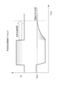
図9に示されるように、センサを駆動するための通電開始から活性判定アドミタンス到達までの時間が短くなると、水蒸気及び/又はリッチガスの蒸発時間は長くなる。また、NOxセンサ24が配置されている部分の流速が遅くなれば、水蒸気及び/又はリッチガスの蒸発時間は長くなる。このような状況に応じて閾値時間を決定することができる。また、搭載車両のミニマム流速に対応した蒸発時間を閾値時間として設定してもよい。
図10に示されるように、回転数と負荷との関係から、水蒸気及び/又はリッチガスの蒸発時間を設定することもできる。例えば、アイドル条件では、50sに設定される。
ステップS106において、時間条件が成立しなければ、ステップS106の判断を繰り返す。ステップS106において、時間条件が成立すれば、ステップS107の処理に進む。ステップS107において、水蒸気及び/又はリッチガスについて、センサ活性判定はONとなる。
続いて、早期活性制御を行う場合のECU10及びSCU40の動作について、図7に示されるフローチャートを参照しながら説明する。
ステップS201では、ECU10がセンサ通電条件成立を判断する。センサ通電条件は、排出ガスセンサであるNOxセンサ24の環境が、乾燥条件を満たしているかどうかで判断される。センサ通電条件が成立していれば、ステップS202の処理に進み、センサ通電条件が成立していなければ、処理を終了する。
ステップS202では、ECU10からSCU40にセンサ駆動許可が送信される。ステップS202に続くステップS203では、SCU40がNOxセンサ24に通電し、センサ駆動が開始される。
ステップS203に続くステップS204では、早期活性制御が実行される。具体的には、ポンプセルに印加される電圧を一時的に上げる。
ステップS204に続くステップS205では、活性制御時間条件が成立しているか否かを判断する。活性制御時間条件に代えて、出力条件が成立しているか否かを判断してもよい。活性制御時間条件の成立は、早期活性制御に起因して発生する水素の影響を排除するための時間の経過を条件とする。出力条件の成立は、モニタセルの出力が実質的に正の値になったことを条件とする。
図11に示されるように、早期活性制御が終了してポンプセルへの電圧印加が終了しても、残存水素の影響により、実際のガス濃度からのずれが発生する。そこで、図11に示されるような水素消滅時間を設定し、水素消滅時間の経過をもって活性制御時間条件が成立しているものとすることができる。
図12では、(A)にモニタセルの電流、(B)に検出NOx濃度、を示している。実線が水素消滅が遅いNOxセンサ、破線は水素消滅が早いNOxセンサの例を示している。いずれの場合も、モニタセル電流の値が0を超えた付近から検出NOx濃度が実際のガス濃度に近くなっている。そこで、モニタセルの出力が実質的に正の値になったことを条件とし、残存水素の影響が排除されたものと判断することができる。尚、モニタセル電流の値は揺らぐことが考えられるので、瞬間的にモニタセル電流の値が正になったのみならず、ある程度継続し又は断続的に数回モニタセル電流の値が正になった場合に、残存水素の影響が排除されたものと判断することが好ましい。また、SCU40のモニタセル電流検出誤差を考慮して、僅かに負側にオフセットした閾値(数nA程度)としてもよい。
ステップS205において、活性制御時間条件又は出力条件が成立しなければ、ステップS205の判断を繰り返す。ステップS106において、活性制御時間条件又は出力時間条件が成立すれば、ステップS206の処理に進む。ステップS206において、水素について、センサ活性判定はONとなる。
図8の(A)は、図6を参照しながら説明した温度条件の成立及び水蒸気/リッチガス蒸発の時間条件成立を示すものである。図8の(B)は、図7を参照しながら説明した水素消滅のための時間条件成立を示すものである。
図8の(A)における時刻t1は、図6のステップS102の処理タイミングである。図8の(A)における時刻t2は、図6のステップS104の処理タイミングである。図8の(A)における時刻t4は、図6のステップS106の処理タイミングである。
図8の(B)における時刻t1は、図7のステップS203,204の処理タイミングである。図8の(B)における時刻t3は、図7のステップ204の処理が終了するタイミングである。図8の(B)における時刻t5は、図7のステップS205の処理タイミングである。
従って、早期活性制御を行わない場合、図6を参照しながら説明した温度条件の成立及び水蒸気/リッチガス蒸発の時間条件成立をもって、NOxセンサ24の活性化が完了したと判断することができる。一方、早期活性制御を行う場合、図6を参照しながら説明した温度条件の成立及び水蒸気/リッチガス蒸発の時間条件成立と、図7を参照しながら説明した水素消滅のための時間条件成立と、の双方の条件が成立した場合に、NOxセンサ24の活性化が完了したと判断することができる。
図6を参照しながら説明した温度条件の成立を利用して、NOxセンサ24の異常判定を行うことができる。NOxセンサ24が正常の場合、図13に示されるように、温度条件の成立及び水蒸気/リッチガス蒸発の時間条件成立後に異常判定開始タイミングが到来するので、活性異常フラグは不定から正常に遷移される。
一方、NOxセンサ24が異常の場合、図14に示されるように、異常判定開始タイミングが到来しても温度条件も時間条件も不成立となっているので、活性異常フラグは不定から異常に遷移される。
本実施形態のマイコン406は、排出ガスセンサであるNOxセンサ24の制御装置であって、内燃機関20から排出される排気ガスから酸素を除去するための第1セルであるポンプセルの温度を示す第1パラメータ、及び第1セルであるポンプセルの作動により酸素が除去された測定対象ガスに含まれる測定対象成分を検出するための第2セルであるセンサセル及びモニタセルの温度を示す第2パラメータを取得する昇温判定部406aと、NOxセンサ24が、所定の精度を確保し測定可能な活性状態になったか否かを判断する活性判定部406bと、を備えている。
昇温判定部406aは、第1パラメータ及び第2パラメータの少なくとも一方が予め定められた温度閾値を超えたかによって、第1セル及び第2セルの昇温条件成立を判断し、活性判定部406bは、昇温条件成立後、温度閾値に対応する時間条件が成立している場合に、NOxセンサ24が活性状態になっていると判断する。
昇温条件成立によって、排出ガスセンサであるNOxセンサ24を構成する第1セル又は第2セルが活性状態の必要条件を満たしていると判断することができる。この昇温条件に加えて、時間条件の成立を判断することで、NOxセンサ24内において検出精度を確保する阻害要因となるガスの濃度低下も判断することができるので、より精度の高い活性判定を行うことができる。時間条件の成立は、第1セル及び第2セルの昇温条件成立を判断するための温度閾値に対応して判断するようにしているので、温度閾値が高く設定されたり低く設定されたりした場合であっても、その設定値に応じた阻害要因ガスの濃度低下を判断することができる。
また本実施形態では、時間条件は、昇温条件成立後において第2セルに対する水蒸気及び/又はリッチガスの影響が排除される時間が確保されるように設定される。
時間条件は、昇温条件成立後において第2セルに対する水蒸気及び/又はリッチガスの影響が排除される時間が確保されるように設定されるので、阻害要因ガスとしての水蒸気及び/又はリッチガスの影響を確実に排除し、より精度の高い活性判定を行うことができる。
また本実施形態では、第1パラメータ及び第2パラメータの少なくとも一方は、交流電圧印加時のアドミタンス又はインピーダンスである。昇温判定に用いるパラメータとして、交流電圧印加時のアドミタンス又はインピーダンスを用いるので、的確に昇温判定を行うことができる。
また本実施形態では、更に、時間条件の成立を判断するための所定時間を設定する時間設定部406cを備え、時間設定部406cは、第1セル及び第2セルへの通電を開始してから昇温条件成立までの時間に基づいて所定時間を設定する。
第1セル及び第2セルへの通電を開始してから昇温条件成立までの時間は、セルの反応能力によって変動するものなので、この時間に応じて所定時間を設定することで、時間条件の成立判断を最適化することができる。
また本実施形態では、更に、時間条件の成立を判断するための所定時間を設定する時間設定部406cを備え、時間設定部406cは、NOxセンサ24が設けられている環境又は内燃機関20の運転条件に基づいて所定時間を設定する。
排出ガスセンサが設けられている環境や内燃機関の運転条件は、阻害要因ガスの濃度低下に影響を与えるので、これらを勘案して所定時間を設定することで、環境や運転条件に応じた時間条件の設定が可能になる。
また本実施形態では、更に、内燃機関20の始動時に第1セルへの印加電圧を一時的に高める早期活性制御を実行する早期活性部406dを備えている。早期活性部406dは、早期活性制御が完了する早期活性完了条件を判断する。活性判定部406bは、昇温条件、時間条件及び早期活性完了条件がともに成立し、早期活性制御に起因して発生する水素の影響を排除するための活性制御時間条件が成立している場合に、排出ガスセンサが活性状態になっていると判断する。早期活性制御によって発生する水素の影響を勘案した活性状態の判定が可能になるので、早期活性の効果を活かして早期の活性判定を行うことができる。
また本実施形態では、NOxセンサ24は、第2セルとして、第1セルの作動により酸素が除去された測定対象ガスに含まれる酸素濃度を検出するためのモニタセルを有しており、活性判定部406bは、昇温条件成立後、活性制御時間条件の成立に代えてモニタセルの出力が水素の影響が排除されたものを示す場合に、NOxセンサ24が活性状態になっていると判断する。水素の影響が排除されたことをモニタセルで確認することができるので、より早期かつ高精度に活性状態の判断が可能となる。
また本実施形態では、活性判定部406bは、昇温条件が所定時間経過しても成立しない場合、NOxセンサ24に異常が発生していると判断する。所定時間内に条件成立をしないことで、NOxセンサ24の異常を判断することができるので、無駄な時間を費やすこと無く異常判断を行うことができる。
また、本実施形態では、第1パラメータ及び第2パラメータの少なくとも一方が、交流電圧印加時のアドミタンス、またはインピーダンスが、予め定められた閾値を超えたか否かによって昇温条件を判断しているが、昇温条件の判断手法はこれに限るものではない。例えば、第1パラメータ、及び第2パラメータに対応するそれぞれの閾値を予め設定し、第1パラメータ、第2パラメータがいずれも各々設定された閾値を超えたか否かによって昇温条件を判断するように構成しても良い。これによれば、第1パラメータ及び第2パラメータの両方に基づいて昇温判定を行うので確実に活性状態を判断することができる。
例えば、本実施形態では、ディーゼル酸化触媒コンバータ22と尿素添加インジェクタ26との間にNOxセンサ24が、SCR触媒コンバータ28の下流側にNOxセンサ30がそれぞれ配置されているが、変形例1として、ディーゼル酸化触媒コンバータの流れ方向の上流側に、更にNOx吸蔵還元触媒であるLNT(Lean NOx Trap)を設けてもよい。
LNTは、NOx吸蔵材とセラミックス製の担体からなる。LNTは、排ガス中のNOxをエンジンの状態がリーン状態のときにカリウムなどのアルカリ金属、またはバリウムなどのアルカリ土類金属からなるNOx吸蔵材に一旦吸蔵させ、エンジンの状態をリッチ状態にすることで排ガス中にHCを供給して、吸蔵されたNOxを放出させる。そして、放出させたNOxを下流側に設けられているSCR触媒コンバータの機能により還元する。
このような構成においては、NOxセンサは、LNTの上流側にさらに設けることができる。すなわち、NOxセンサは、NOx吸蔵還元触媒の上流側、ディーゼル酸化触媒コンバータ22と尿素添加インジェクタ26との間、及びSCR触媒コンバータ28の下流側に、それぞれ設けることができる。そして、それぞれのNOxセンサが、一つのSCUに接続されている。その他は、上記実施形態と同様である。
この構成によれば、LNT上流側のNOx濃度を検知し、検出されたNOx濃度をSCU40からECU10に送信することで、ECU10側でエンジンの状態をリッチかリーンかに切り替えることができる。
一方で、LNT上流側のNOxセンサは、エンジンから排出された排ガスが還元触媒等を通らないガスであることが多いために他ガスを多く含み、NOxセンサの検知に際して他ガスの影響が大きい。したがって、LNT上流側のNOxセンサの活性判定では、実施例中において、ステップS105に相当する昇温条件成立後におけるセンサセル及びモニタセルに対する水蒸気及び/又はリッチガスの影響が排除される時間を長く設定する必要がある。
すなわち、LNT上流側に用いられるNOxセンサに本発明を適用する場合には、第1パラメータ、または第2パラメータが昇温条件成立のための活性判定アドミタンスThaを超えてから、活性判定ONまでの時間条件は、LNTの下流に設けられているNOxセンサよりも長く設定されていることが好ましい。これにより、水蒸気及び/又はリッチガスの影響が排除される時間が、LNT下流側に設けられたNOxセンサよりも長くなるので、NOzセンサの検出精度を確保する阻害要因となるガスの影響を考慮し、精度良くNOxセンサの活性を判定することができる。
また、変形例2としては、変形例1におけるLNT上流に設けられているNOxセンサを、LNTとディーゼル酸化触媒コンバータとの間に設けることもできる。このような構成では、NOxセンサは、LNTとディーゼル酸化触媒コンバータとの間、ディーゼル酸化触媒コンバータ22と尿素添加インジェクタ26との間、及びSCR触媒コンバータ28の下流側に、それぞれ設けることができる。
このような構成であっても、当該NOxセンサは、排ガスが還元触媒等を通らないガスであるので、やはり他ガスの影響が大きいものとなる。したがって、変形例1のように、LNTとディーゼル酸化触媒コンバータとの間に設けたNOxセンサにおける昇温条件成立のための活性判定アドミタンスThaに対して、第1パラメータ、または第2パラメータが当該判定のアドミタンスThaを超えてから活性判定ONまでの時間条件は、ディーゼル酸化触媒コンバータ22と尿素添加インジェクタ26との間、またはSCR触媒コンバータ28の下流側に設けられたNOxセンサよりも長く設定されていることが好ましい。
これにより、水蒸気及び/又はリッチガスの影響が排除される時間が、ディーゼル酸化触媒コンバータ22と尿素添加インジェクタ26との間、またはSCR触媒コンバータ28の下流側に設けられたNOxセンサよりも長くなるので、NOzセンサの検出精度を確保する阻害要因となるガスの影響を考慮し、精度良くNOxセンサの活性を判定することができる。
以上、具体例を参照しつつ本実施形態について説明した。しかし、本開示はこれらの具体例に限定されるものではない。これら具体例に、当業者が適宜設計変更を加えたものも、本開示の特徴を備えている限り、本開示の範囲に包含される。前述した各具体例が備える各要素およびその配置、条件、形状などは、例示したものに限定されるわけではなく適宜変更することができる。前述した各具体例が備える各要素は、技術的な矛盾が生じない限り、適宜組み合わせを変えることができる。
Claims (9)
- 排出ガスセンサの制御装置であって、
内燃機関から排出される排気ガスから酸素を除去するための第1セルの温度を示す第1パラメータ、又は前記第1セルの作動により酸素が除去された測定対象ガスに含まれる測定対象成分を検出するための第2セルの温度を示す第2パラメータを取得する昇温判定部(406a)と、
前記排出ガスセンサが、所定の精度を確保し測定可能な活性状態になったか否かを判断する活性判定部(406b)と、を備え、
前記昇温判定部は、前記第1パラメータ又は前記第2パラメータが予め定められた温度閾値を超えたかによって、前記第1セル又は前記第2セルの昇温条件成立を判断し、
前記活性判定部は、前記昇温条件成立後、前記温度閾値に対応する時間条件が成立している場合に、前記排出ガスセンサが活性状態になっていると判断する、制御装置。 - 請求項1に記載の制御装置であって、
前記昇温判定部は、前記第1パラメータ及び前記第2パラメータを取得し、前記第1パラメータ及び前記第2パラメータが各々予め定められた温度閾値を超えたかによって、前記第1セル及び前記第2セルの昇温条件成立を判断する、制御装置。 - 請求項1又は2に記載の制御装置であって、
前記第1パラメータ及び前記第2パラメータの少なくとも一方は、交流電圧印加時のアドミタンス又はインピーダンスである、制御装置。 - 請求項1から3のいずれか1項に記載の制御装置であって、
更に、前記時間条件の成立を判断するための所定時間を設定する時間設定部(406c)を備え、
前記時間設定部は、前記第1セル及び前記第2セルへの通電を開始してから前記昇温条件成立までの時間に基づいて前記所定時間を設定する、制御装置。 - 請求項1から3のいずれか1項に記載の制御装置であって、
更に、前記時間条件の成立を判断するための所定時間を設定する時間設定部(406c)を備え、
前記時間設定部は、前記排出ガスセンサが設けられている環境又は前記内燃機関の運転条件に基づいて前記所定時間を設定する、制御装置。 - 請求項1から3のいずれか1項に記載の制御装置であって、
更に、内燃機関の始動時に前記第1セルへの印加電圧を一時的に高める早期活性制御を実行する早期活性部(406d)を備え、
前記早期活性部は、前記早期活性制御が完了する早期活性完了条件を判断し、
前記活性判定部は、前記昇温条件、前記時間条件及び前記早期活性完了条件がともに成立し、早期活性制御に起因して発生する水素の影響を排除するための活性制御時間条件が成立している場合に、前記排出ガスセンサが活性状態になっていると判断する、制御装置。 - 請求項6に記載の制御装置であって、
前記排出ガスセンサは、前記第2セルとして、前記第1セルの作動により酸素が除去された測定対象ガスに含まれる酸素濃度を検出するためのモニタセルを有しており、
前記活性判定部は、前記昇温条件成立後、前記活性制御時間条件の成立に代えて前記モニタセルの出力が水素の影響が排除されたものを示す場合に、前記排出ガスセンサが活性状態になっていると判断する、制御装置。 - 請求項1から4のいずれか1項に記載の制御装置であって、
前記時間条件は、前記昇温条件成立後において前記第2セルに対する水蒸気及び/又はリッチガスの影響が排除される時間が確保されるように予め設定される、制御装置。 - 請求項1から8のいずれか1項に記載の制御装置であって、
前記活性判定部は、前記昇温条件が所定時間経過しても成立しない場合、前記排出ガスセンサに異常が発生していると判断する、制御装置。
Priority Applications (3)
| Application Number | Priority Date | Filing Date | Title |
|---|---|---|---|
| DE112018004303.7T DE112018004303T5 (de) | 2017-09-29 | 2018-09-18 | Steuerapparat |
| CN201880062171.3A CN111133305B (zh) | 2017-09-29 | 2018-09-18 | 控制装置 |
| US16/832,521 US11092099B2 (en) | 2017-09-29 | 2020-03-27 | Control apparatus |
Applications Claiming Priority (2)
| Application Number | Priority Date | Filing Date | Title |
|---|---|---|---|
| JP2017190369A JP6828647B2 (ja) | 2017-09-29 | 2017-09-29 | 制御装置 |
| JP2017-190369 | 2017-09-29 |
Related Child Applications (1)
| Application Number | Title | Priority Date | Filing Date |
|---|---|---|---|
| US16/832,521 Continuation US11092099B2 (en) | 2017-09-29 | 2020-03-27 | Control apparatus |
Publications (1)
| Publication Number | Publication Date |
|---|---|
| WO2019065366A1 true WO2019065366A1 (ja) | 2019-04-04 |
Family
ID=65902853
Family Applications (1)
| Application Number | Title | Priority Date | Filing Date |
|---|---|---|---|
| PCT/JP2018/034455 Ceased WO2019065366A1 (ja) | 2017-09-29 | 2018-09-18 | 制御装置 |
Country Status (5)
| Country | Link |
|---|---|
| US (1) | US11092099B2 (ja) |
| JP (1) | JP6828647B2 (ja) |
| CN (1) | CN111133305B (ja) |
| DE (1) | DE112018004303T5 (ja) |
| WO (1) | WO2019065366A1 (ja) |
Families Citing this family (2)
| Publication number | Priority date | Publication date | Assignee | Title |
|---|---|---|---|---|
| US12399084B2 (en) | 2022-10-19 | 2025-08-26 | Honeywell International Inc. | Digitally controlled nitrogen oxide (NOx) sensor |
| EP4357601A1 (en) * | 2022-10-19 | 2024-04-24 | Honeywell International Inc. | Digitally controlled nitrogen oxide (nox) sensor |
Citations (5)
| Publication number | Priority date | Publication date | Assignee | Title |
|---|---|---|---|---|
| JP2002005882A (ja) * | 2000-06-15 | 2002-01-09 | Unisia Jecs Corp | 空燃比センサの活性判定装置 |
| JP2004132840A (ja) * | 2002-10-10 | 2004-04-30 | Denso Corp | ガス濃度検出装置 |
| JP2009257889A (ja) * | 2008-04-15 | 2009-11-05 | Toyota Motor Corp | NOxセンサの活性判定装置、異常診断装置及び出力補正装置 |
| JP2015206692A (ja) * | 2014-04-21 | 2015-11-19 | 株式会社デンソー | 排出ガスセンサのヒータ制御装置 |
| JP2016070922A (ja) * | 2014-10-01 | 2016-05-09 | 株式会社デンソー | ガス濃度検出装置 |
Family Cites Families (7)
| Publication number | Priority date | Publication date | Assignee | Title |
|---|---|---|---|---|
| JP2006162325A (ja) * | 2004-12-03 | 2006-06-22 | Toyota Motor Corp | 排気ガス成分濃度検出方法 |
| JP4662207B2 (ja) * | 2005-11-28 | 2011-03-30 | 日本特殊陶業株式会社 | 空燃比検出装置 |
| EP2336759B1 (en) * | 2008-10-09 | 2018-11-21 | Toyota Jidosha Kabushiki Kaisha | Exhaust gas sensor activity assessment device, and internal combustion engine control device |
| JP4768796B2 (ja) * | 2008-11-06 | 2011-09-07 | 日本特殊陶業株式会社 | ガスセンサ制御装置及びガスセンサ制御方法 |
| JP5134065B2 (ja) * | 2009-12-22 | 2013-01-30 | 日本特殊陶業株式会社 | センサ制御装置 |
| JP6241360B2 (ja) * | 2014-04-23 | 2017-12-06 | 株式会社デンソー | 排出ガスセンサのヒータ制御装置 |
| JP2017190369A (ja) | 2016-04-11 | 2017-10-19 | セイコーエプソン株式会社 | インクジェットインク組成物、及び記録方法 |
-
2017
- 2017-09-29 JP JP2017190369A patent/JP6828647B2/ja active Active
-
2018
- 2018-09-18 WO PCT/JP2018/034455 patent/WO2019065366A1/ja not_active Ceased
- 2018-09-18 DE DE112018004303.7T patent/DE112018004303T5/de active Pending
- 2018-09-18 CN CN201880062171.3A patent/CN111133305B/zh active Active
-
2020
- 2020-03-27 US US16/832,521 patent/US11092099B2/en active Active
Patent Citations (5)
| Publication number | Priority date | Publication date | Assignee | Title |
|---|---|---|---|---|
| JP2002005882A (ja) * | 2000-06-15 | 2002-01-09 | Unisia Jecs Corp | 空燃比センサの活性判定装置 |
| JP2004132840A (ja) * | 2002-10-10 | 2004-04-30 | Denso Corp | ガス濃度検出装置 |
| JP2009257889A (ja) * | 2008-04-15 | 2009-11-05 | Toyota Motor Corp | NOxセンサの活性判定装置、異常診断装置及び出力補正装置 |
| JP2015206692A (ja) * | 2014-04-21 | 2015-11-19 | 株式会社デンソー | 排出ガスセンサのヒータ制御装置 |
| JP2016070922A (ja) * | 2014-10-01 | 2016-05-09 | 株式会社デンソー | ガス濃度検出装置 |
Also Published As
| Publication number | Publication date |
|---|---|
| CN111133305A (zh) | 2020-05-08 |
| JP2019066252A (ja) | 2019-04-25 |
| CN111133305B (zh) | 2023-06-20 |
| US20200224600A1 (en) | 2020-07-16 |
| JP6828647B2 (ja) | 2021-02-10 |
| US11092099B2 (en) | 2021-08-17 |
| DE112018004303T5 (de) | 2020-05-07 |
Similar Documents
| Publication | Publication Date | Title |
|---|---|---|
| JP6776533B2 (ja) | ガスセンサの制御装置 | |
| US10564120B2 (en) | Gas concentration detection device | |
| JP2009175013A (ja) | NOxセンサの劣化診断装置 | |
| JP5093672B2 (ja) | NOxセンサの劣化判定制御装置及び劣化回復制御装置 | |
| US20180274428A1 (en) | NOx SENSOR ABNORMALITY DETECTOR | |
| CN108956867B (zh) | 气体传感器控制设备 | |
| CN110678744A (zh) | 气体传感器控制装置 | |
| JP6455185B2 (ja) | 内燃機関制御装置 | |
| US11774403B2 (en) | Gas sensor control device | |
| JP6828647B2 (ja) | 制御装置 | |
| JP2009175014A (ja) | NOxセンサ及びその劣化診断装置 | |
| JP2016156667A (ja) | 排気センサ | |
| JP6380022B2 (ja) | センサ制御装置 | |
| JP6708168B2 (ja) | ガスセンサ制御装置 | |
| WO2018123946A1 (ja) | 異常判断装置 | |
| WO2018221528A1 (ja) | ガスセンサ制御装置 | |
| JP6809428B2 (ja) | 制御装置 | |
| JP6984696B2 (ja) | ガスセンサの制御装置 | |
| JP2017116309A (ja) | 内燃機関のガス濃度検出装置 | |
| JP2019124185A (ja) | 制御装置 |
Legal Events
| Date | Code | Title | Description |
|---|---|---|---|
| 121 | Ep: the epo has been informed by wipo that ep was designated in this application |
Ref document number: 18860722 Country of ref document: EP Kind code of ref document: A1 |
|
| 122 | Ep: pct application non-entry in european phase |
Ref document number: 18860722 Country of ref document: EP Kind code of ref document: A1 |