WO2019065014A1 - 車両用指針計器 - Google Patents
車両用指針計器 Download PDFInfo
- Publication number
- WO2019065014A1 WO2019065014A1 PCT/JP2018/031063 JP2018031063W WO2019065014A1 WO 2019065014 A1 WO2019065014 A1 WO 2019065014A1 JP 2018031063 W JP2018031063 W JP 2018031063W WO 2019065014 A1 WO2019065014 A1 WO 2019065014A1
- Authority
- WO
- WIPO (PCT)
- Prior art keywords
- pointer
- output shaft
- press
- gear
- rotation
- Prior art date
- Legal status (The legal status is an assumption and is not a legal conclusion. Google has not performed a legal analysis and makes no representation as to the accuracy of the status listed.)
- Ceased
Links
Images


Classifications
-
- H—ELECTRICITY
- H02—GENERATION; CONVERSION OR DISTRIBUTION OF ELECTRIC POWER
- H02K—DYNAMO-ELECTRIC MACHINES
- H02K7/00—Arrangements for handling mechanical energy structurally associated with dynamo-electric machines, e.g. structural association with mechanical driving motors or auxiliary dynamo-electric machines
- H02K7/10—Structural association with clutches, brakes, gears, pulleys or mechanical starters
- H02K7/116—Structural association with clutches, brakes, gears, pulleys or mechanical starters with gears
-
- B—PERFORMING OPERATIONS; TRANSPORTING
- B60—VEHICLES IN GENERAL
- B60K—ARRANGEMENT OR MOUNTING OF PROPULSION UNITS OR OF TRANSMISSIONS IN VEHICLES; ARRANGEMENT OR MOUNTING OF PLURAL DIVERSE PRIME-MOVERS IN VEHICLES; AUXILIARY DRIVES FOR VEHICLES; INSTRUMENTATION OR DASHBOARDS FOR VEHICLES; ARRANGEMENTS IN CONNECTION WITH COOLING, AIR INTAKE, GAS EXHAUST OR FUEL SUPPLY OF PROPULSION UNITS IN VEHICLES
- B60K35/00—Instruments specially adapted for vehicles; Arrangement of instruments in or on vehicles
- B60K35/20—Output arrangements, i.e. from vehicle to user, associated with vehicle functions or specially adapted therefor
- B60K35/21—Output arrangements, i.e. from vehicle to user, associated with vehicle functions or specially adapted therefor using visual output, e.g. blinking lights or matrix displays
- B60K35/214—Variable gauge scales, e.g. scale enlargement to adapt to maximum driving speed
-
- B—PERFORMING OPERATIONS; TRANSPORTING
- B60—VEHICLES IN GENERAL
- B60K—ARRANGEMENT OR MOUNTING OF PROPULSION UNITS OR OF TRANSMISSIONS IN VEHICLES; ARRANGEMENT OR MOUNTING OF PLURAL DIVERSE PRIME-MOVERS IN VEHICLES; AUXILIARY DRIVES FOR VEHICLES; INSTRUMENTATION OR DASHBOARDS FOR VEHICLES; ARRANGEMENTS IN CONNECTION WITH COOLING, AIR INTAKE, GAS EXHAUST OR FUEL SUPPLY OF PROPULSION UNITS IN VEHICLES
- B60K35/00—Instruments specially adapted for vehicles; Arrangement of instruments in or on vehicles
- B60K35/20—Output arrangements, i.e. from vehicle to user, associated with vehicle functions or specially adapted therefor
- B60K35/28—Output arrangements, i.e. from vehicle to user, associated with vehicle functions or specially adapted therefor characterised by the type of the output information, e.g. video entertainment or vehicle dynamics information; characterised by the purpose of the output information, e.g. for attracting the attention of the driver
-
- B—PERFORMING OPERATIONS; TRANSPORTING
- B60—VEHICLES IN GENERAL
- B60K—ARRANGEMENT OR MOUNTING OF PROPULSION UNITS OR OF TRANSMISSIONS IN VEHICLES; ARRANGEMENT OR MOUNTING OF PLURAL DIVERSE PRIME-MOVERS IN VEHICLES; AUXILIARY DRIVES FOR VEHICLES; INSTRUMENTATION OR DASHBOARDS FOR VEHICLES; ARRANGEMENTS IN CONNECTION WITH COOLING, AIR INTAKE, GAS EXHAUST OR FUEL SUPPLY OF PROPULSION UNITS IN VEHICLES
- B60K35/00—Instruments specially adapted for vehicles; Arrangement of instruments in or on vehicles
- B60K35/60—Instruments characterised by their location or relative disposition in or on vehicles
-
- G—PHYSICS
- G01—MEASURING; TESTING
- G01D—MEASURING NOT SPECIALLY ADAPTED FOR A SPECIFIC VARIABLE; ARRANGEMENTS FOR MEASURING TWO OR MORE VARIABLES NOT COVERED IN A SINGLE OTHER SUBCLASS; TARIFF METERING APPARATUS; MEASURING OR TESTING NOT OTHERWISE PROVIDED FOR
- G01D13/00—Component parts of indicators for measuring arrangements not specially adapted for a specific variable
- G01D13/02—Scales; Dials
- G01D13/04—Construction
-
- G—PHYSICS
- G01—MEASURING; TESTING
- G01D—MEASURING NOT SPECIALLY ADAPTED FOR A SPECIFIC VARIABLE; ARRANGEMENTS FOR MEASURING TWO OR MORE VARIABLES NOT COVERED IN A SINGLE OTHER SUBCLASS; TARIFF METERING APPARATUS; MEASURING OR TESTING NOT OTHERWISE PROVIDED FOR
- G01D13/00—Component parts of indicators for measuring arrangements not specially adapted for a specific variable
- G01D13/22—Pointers, e.g. settable pointer
-
- H—ELECTRICITY
- H02—GENERATION; CONVERSION OR DISTRIBUTION OF ELECTRIC POWER
- H02K—DYNAMO-ELECTRIC MACHINES
- H02K1/00—Details of the magnetic circuit
- H02K1/06—Details of the magnetic circuit characterised by the shape, form or construction
- H02K1/12—Stationary parts of the magnetic circuit
- H02K1/14—Stator cores with salient poles
-
- H—ELECTRICITY
- H02—GENERATION; CONVERSION OR DISTRIBUTION OF ELECTRIC POWER
- H02K—DYNAMO-ELECTRIC MACHINES
- H02K21/00—Synchronous motors having permanent magnets; Synchronous generators having permanent magnets
- H02K21/12—Synchronous motors having permanent magnets; Synchronous generators having permanent magnets with stationary armatures and rotating magnets
- H02K21/14—Synchronous motors having permanent magnets; Synchronous generators having permanent magnets with stationary armatures and rotating magnets with magnets rotating within the armatures
-
- H—ELECTRICITY
- H02—GENERATION; CONVERSION OR DISTRIBUTION OF ELECTRIC POWER
- H02K—DYNAMO-ELECTRIC MACHINES
- H02K37/00—Motors with rotor rotating step by step and without interrupter or commutator driven by the rotor, e.g. stepping motors
- H02K37/10—Motors with rotor rotating step by step and without interrupter or commutator driven by the rotor, e.g. stepping motors of permanent magnet type
- H02K37/12—Motors with rotor rotating step by step and without interrupter or commutator driven by the rotor, e.g. stepping motors of permanent magnet type with stationary armatures and rotating magnets
- H02K37/14—Motors with rotor rotating step by step and without interrupter or commutator driven by the rotor, e.g. stepping motors of permanent magnet type with stationary armatures and rotating magnets with magnets rotating within the armatures
-
- H—ELECTRICITY
- H02—GENERATION; CONVERSION OR DISTRIBUTION OF ELECTRIC POWER
- H02K—DYNAMO-ELECTRIC MACHINES
- H02K37/00—Motors with rotor rotating step by step and without interrupter or commutator driven by the rotor, e.g. stepping motors
- H02K37/24—Structural association with auxiliary mechanical devices
-
- B—PERFORMING OPERATIONS; TRANSPORTING
- B60—VEHICLES IN GENERAL
- B60K—ARRANGEMENT OR MOUNTING OF PROPULSION UNITS OR OF TRANSMISSIONS IN VEHICLES; ARRANGEMENT OR MOUNTING OF PLURAL DIVERSE PRIME-MOVERS IN VEHICLES; AUXILIARY DRIVES FOR VEHICLES; INSTRUMENTATION OR DASHBOARDS FOR VEHICLES; ARRANGEMENTS IN CONNECTION WITH COOLING, AIR INTAKE, GAS EXHAUST OR FUEL SUPPLY OF PROPULSION UNITS IN VEHICLES
- B60K2360/00—Indexing scheme associated with groups B60K35/00 or B60K37/00 relating to details of instruments or dashboards
- B60K2360/16—Type of output information
- B60K2360/164—Infotainment
-
- B—PERFORMING OPERATIONS; TRANSPORTING
- B60—VEHICLES IN GENERAL
- B60K—ARRANGEMENT OR MOUNTING OF PROPULSION UNITS OR OF TRANSMISSIONS IN VEHICLES; ARRANGEMENT OR MOUNTING OF PLURAL DIVERSE PRIME-MOVERS IN VEHICLES; AUXILIARY DRIVES FOR VEHICLES; INSTRUMENTATION OR DASHBOARDS FOR VEHICLES; ARRANGEMENTS IN CONNECTION WITH COOLING, AIR INTAKE, GAS EXHAUST OR FUEL SUPPLY OF PROPULSION UNITS IN VEHICLES
- B60K2360/00—Indexing scheme associated with groups B60K35/00 or B60K37/00 relating to details of instruments or dashboards
- B60K2360/16—Type of output information
- B60K2360/167—Vehicle dynamics information
-
- B—PERFORMING OPERATIONS; TRANSPORTING
- B60—VEHICLES IN GENERAL
- B60K—ARRANGEMENT OR MOUNTING OF PROPULSION UNITS OR OF TRANSMISSIONS IN VEHICLES; ARRANGEMENT OR MOUNTING OF PLURAL DIVERSE PRIME-MOVERS IN VEHICLES; AUXILIARY DRIVES FOR VEHICLES; INSTRUMENTATION OR DASHBOARDS FOR VEHICLES; ARRANGEMENTS IN CONNECTION WITH COOLING, AIR INTAKE, GAS EXHAUST OR FUEL SUPPLY OF PROPULSION UNITS IN VEHICLES
- B60K2360/00—Indexing scheme associated with groups B60K35/00 or B60K37/00 relating to details of instruments or dashboards
- B60K2360/16—Type of output information
- B60K2360/171—Vehicle or relevant part thereof displayed
-
- B—PERFORMING OPERATIONS; TRANSPORTING
- B60—VEHICLES IN GENERAL
- B60K—ARRANGEMENT OR MOUNTING OF PROPULSION UNITS OR OF TRANSMISSIONS IN VEHICLES; ARRANGEMENT OR MOUNTING OF PLURAL DIVERSE PRIME-MOVERS IN VEHICLES; AUXILIARY DRIVES FOR VEHICLES; INSTRUMENTATION OR DASHBOARDS FOR VEHICLES; ARRANGEMENTS IN CONNECTION WITH COOLING, AIR INTAKE, GAS EXHAUST OR FUEL SUPPLY OF PROPULSION UNITS IN VEHICLES
- B60K2360/00—Indexing scheme associated with groups B60K35/00 or B60K37/00 relating to details of instruments or dashboards
- B60K2360/60—Structural details of dashboards or instruments
- B60K2360/68—Features of instruments
- B60K2360/691—Housings
-
- B—PERFORMING OPERATIONS; TRANSPORTING
- B60—VEHICLES IN GENERAL
- B60K—ARRANGEMENT OR MOUNTING OF PROPULSION UNITS OR OF TRANSMISSIONS IN VEHICLES; ARRANGEMENT OR MOUNTING OF PLURAL DIVERSE PRIME-MOVERS IN VEHICLES; AUXILIARY DRIVES FOR VEHICLES; INSTRUMENTATION OR DASHBOARDS FOR VEHICLES; ARRANGEMENTS IN CONNECTION WITH COOLING, AIR INTAKE, GAS EXHAUST OR FUEL SUPPLY OF PROPULSION UNITS IN VEHICLES
- B60K2360/00—Indexing scheme associated with groups B60K35/00 or B60K37/00 relating to details of instruments or dashboards
- B60K2360/60—Structural details of dashboards or instruments
- B60K2360/68—Features of instruments
- B60K2360/698—Pointers of combined instruments
Definitions
- the present disclosure relates to a pointer instrument for a vehicle.
- a pointer instrument for a vehicle in which a rotary pointer is rotationally driven by a step motor
- a rotary pointer is provided integrally rotatable with respect to an output gear accommodated in a casing in a step motor.
- the rotary shaft of the rotary pointer may be changed to be press-fit into the output gear. Conceivable.
- the rotation shaft is inserted on the inner peripheral side of the gear portion that is the final stage of the output gear. Therefore, when the rotation shaft is press-fit to the inner peripheral side of the final stage gear portion according to this, the press-in distortion is easily propagated to the final stage gear portion close to the press-fit portion.
- An object of the present disclosure is to provide a pointer instrument for a vehicle that avoids the rotation failure of the rotation pointer.
- a vehicle pointer instrument includes a rotary pointer for indicating a vehicle state value, and a step motor for rotating and driving the rotary pointer.
- the step motor has an output gear having an output shaft portion integrally rotating with a rotary pointer, and a final gear portion extending outward from the output shaft portion, and a reduction gear meshing with the final gear portion.
- a reduction gear mechanism and a motor casing accommodating an output gear and the reduction gear mechanism.
- the rotary pointer has a rotary shaft which is press-fitted in the motor casing at a specific position axially shifted from the final stage gear portion in the output shaft portion.
- the rotation axis of the rotary pointer is press-fit at a specific location axially shifted from the final stage gear in the output shaft of the output gear, the final stage gear separated from the specific location by the offset It is difficult for propagation of press-in distortion to the part. Therefore, even in the motor casing, it is possible to suppress that the final stage gear portion plastically deforms due to the propagation of the press-in distortion to cause the meshing failure with the reduction gear. According to this, it is possible to avoid the rotation failure of the rotary pointer caused by the meshing failure between the final stage gear portion and the reduction gear.
- the rotary pointer may have a pointer main body that protrudes outward from the rotary shaft to indicate a vehicle state value.
- the rotation shaft may be press-fit at a specific position shifted from the final stage gear portion toward the pointer main body side in the axial direction in the output shaft portion.
- the gravity center position on the rotary shaft tends to be biased toward the pointer main body side. Therefore, with the rotary shaft that is pressed into a specific location that is shifted from the final stage gear to the pointer main body side in the axial direction in the output shaft, the specific location approaches or overlaps the center of gravity, and the inclination relative to the original rotation center line It becomes difficult to occur with the output shaft. According to this, it is possible to avoid the rotation failure of the rotary pointer caused by the inclination of the rotary shaft, in addition to the rotation failure of the rotary pointer caused by the poor meshing between the final stage gear portion and the reduction gear.
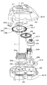
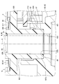
- FIG. 2 is a cross-sectional view showing a pointer instrument for a vehicle including a step motor according to one embodiment, and is a cross-sectional view taken along line II-II of FIG. 1 is an exploded perspective view of a stepper motor according to one embodiment. It is a top view showing the inside of the step motor by one embodiment. It is a perspective view showing the inside of the step motor by one embodiment. It is sectional drawing which expands and shows a part of FIG. It is sectional drawing which expands and shows a part of FIG. It is sectional drawing which shows the modification of FIG. It is sectional drawing which shows the modification of FIG. It is sectional drawing which shows the modification of FIG. It is sectional drawing which shows the modification of FIG. It is sectional drawing which shows the modification of FIG. It is sectional drawing which shows the modification of FIG. It is sectional drawing which shows the modification of FIG. It is sectional drawing which shows the modification of FIG. It is sectional drawing which shows the modification of FIG.
- a pointer 1 for a vehicle is installed in an instrument panel in a vehicle.
- the vehicle pointer instrument 1 includes a display member 2, a rotation pointer 4 and a step motor 6.
- “visual side” means the side on which the occupant of the driver's seat visually recognizes the display of the pointer instrument 1 in the vehicle
- the “anti-visual side” means the visual side. "Means the other side.
- the display member 2 is formed by laminating a light shielding print layer on a light transmitting substrate such as polycarbonate resin, and has a flat plate shape as a whole.
- the display surface 2a which is one surface of the display member 2 is disposed toward the viewing side.
- the open part of the light shielding print layer in the display member 2 is formed with a numeral and scale aligned in the rotational direction of the rotary pointer 4 as the indicator 20 in order to display the "vehicle condition value".
- the vehicle state value of the present embodiment is a vehicle speed value as shown in FIG. 1, but may be a physical quantity such as an engine rotational speed related to the vehicle.
- the opened portion of the light shielding print layer forms a warning lamp 21 for emitting a warning around the rotation axis 41 of the rotary pointer 4.
- the rotation pointer 4 is formed of a translucent resin material such as acrylic resin, and has a pointer main body 40 and a rotation shaft 41.
- the pointer body 40 has an elongated needle shape as a whole, and is disposed closer to the viewing side than the display surface 2 a of the display member 2.
- the pointer body 40 indicates the vehicle state value represented by the index 20 by the tip 40 a according to the rotational position.
- the rotary shaft 41 has a cylindrical shape extending from the proximal end 40 b of the pointer body 40 to the anti-viewing side as a whole. As a result, the pointer main body 40 is cantilevered on the outer peripheral side from the rotary shaft 41.
- the rotary shaft 41 is inserted into the pointer hole 22 penetrating between the both surfaces 2 a and 2 b in the display member 2.
- the rotating shaft 41 is connected to the step motor 6 on the side opposite to the viewing side of the rear surface 2 b of the display member 2.
- the step motor 6 rotationally drives the rotary pointer 4 around the rotation center line C, which is an axis of the rotary shaft 41, to realize the above-mentioned instruction from the pointer main body 40.
- the step motor 6 is disposed on the anti-viewing side relative to the back surface 2 b of the display member 2.
- the step motor 6 includes a motor casing 60, a motor main body 63, a motor substrate 64, and light sources 65 and 66.
- the motor casing 60 is a combination of a pair of case members 61 and 62, and has a hollow shape as a whole.
- Each case member 61, 62 is formed of a light shielding resin material such as a modified polyphenylene ether resin (m-PPE) and is formed in a cup shape.
- the respective case members 61 and 62 are coupled to each other by snap fit fitting in a state in which the respective opening edges 610 and 620 overlap each other.
- the case members 61 and 62 form through holes 612 and 622 which penetrate the bottoms 611 and 621 on the rotation center line C of the pointer body 40.
- the first case member 61 is disposed to face the back surface 2 b on the non-viewing side of the display member 2.
- the second case member 62 is disposed closer to the anti-viewing side than the first case member 61.
- the motor substrate 64 is formed by laminating a metal wiring layer on a printed circuit board such as a glass epoxy substrate, and has a flat plate shape as a whole.
- the motor substrate 64 is disposed on the anti-viewing side of the motor casing 60.
- the mounting surface 640 which is one surface of the motor substrate 64 has a planar shape. The mounting surface 640 holds the motor casing 60 and the light sources 65 and 66.
- the motor main body 63 is accommodated in the motor casing 60.
- the motor body 63 is mounted on the mounting surface 640 of the motor substrate 64 via the motor casing 60.
- the motor main body 63 includes a drive source D, a reduction mechanism R, and a rotation output mechanism O.
- the drive source D is a combination of the yoke 630, the two-phase coils 631a and 631b, and the magnet rotor 632 and is disposed radially deviated from the rotation center line C of the pointer body 40.
- the yoke 630 is formed in a frame shape by a magnetic metal material such as iron and fixed to the motor casing 60.
- the yoke 630 has a pair of magnetic poles 630a and 630b protruding to the inner peripheral side.
- the A-phase coil 631a is wound around one magnetic pole 630a
- the B-phase coil 631b is wound around the other magnetic pole 630b.
- the coils 631 a and 631 b of phases A and B are electrically connected to the metal wiring layer of the motor substrate 64 through the through holes penetrating the second case member 62 of the motor casing 60.
- the magnet rotor 632 is formed in the shape of a disk from a magnetic metal material such as ferrite, and is disposed on the inner peripheral side of the yoke 630 with a gap between each magnetic pole 630 a and 630 b.
- the magnet rotor 632 is radially supported and thrust supported by the motor casing 60 so as to be rotatable about an axis substantially parallel to the rotation center line C of the pointer body 40.
- N and S poles as magnetic poles are alternately magnetized in the rotational direction.
- the reduction mechanism R is a combination of a magnet gear 634, an idle gear 635, and a pinion gear 636 as a reduction gear, and is disposed radially away from the rotation center line C of the pointer body 40.
- the magnet gear 634 is formed of a hard resin material such as polyacetal resin (POM) and has a spur gear shape.
- the magnet gear 634 is radially supported and thrust supported by the motor casing 60 so as to be integrally rotatable with the magnet rotor 632.
- the idle gear 635 and the pinion gear 636 are integrally and coaxially formed of a hard resin material such as polybutylene terephthalate resin (PBT), and each have a spur gear shape.
- PBT polybutylene terephthalate resin
- the idle gear 635 and the pinion gear 636 are radially supported and thrust supported by the motor casing 60 so as to be integrally rotatable around an axis substantially parallel to the rotation center line C of the pointer body 40.
- the idle gear 635 decelerates the rotation of the gear 634 by meshing with the magnet gear 634.
- the rotation output mechanism O is a combination of the output gear 638 and the rotation stopper 638 a, and is disposed on the rotation center line C of the pointer body 40.
- the output gear 638 and the rotation stopper 638a are integrally formed of a hard resin material such as polyacetal resin (POM).
- POM polyacetal resin
- the output gear 638 and the rotation stopper 638 a are radially supported and thrust-supported by the motor casing 60 so as to be integrally rotatable around the rotation center line C of the pointer body 40.
- the output gear 638 integrally includes an output shaft 637 and a final gear portion 639.
- the output shaft portion 637 has a cylindrical shape forming the central hole 637a as a whole.
- the central hole 637a of the output shaft portion 637 is coaxially opened toward the through hole 612 which penetrates the first case member 61 in the motor casing 60 in the axial direction, and the central hole 637a of the output shaft portion 637
- the rotary shaft 41 of the rotary pointer 4 is coaxially press-fitted. As a result, the output shaft portion 637 rotates with the rotary pointer 4 around the rotation center line C, thereby outputting a rotational torque to the pointer 4.
- the final stage gear portion 639 has a spur gear shape that extends from the output shaft portion 637 to the outer peripheral side.
- the final gear portion 639 decelerates the rotation of the gear 636 by meshing with the pinion gear 636 in the reduction mechanism R. From the above configuration, in the motor main body 63, the rotational torque that is increased from the drive source D through the decelerating action of the reduction mechanism R is given from the rotational output mechanism O to the rotational pointer 4.
- the rotation stopper 638 a has a projecting piece shape which protrudes from the final stage gear portion 639 to the viewing side.
- the rotation stopper 638 a is provided so as to be able to be locked by the fixed stopper of the motor casing 60 at the limit positions on both sides which determine the rotation range of the rotation pointer 4. Thus, even if rotational torque is applied from the rotation output mechanism O to the rotary pointer 4, the rotation of the pointer 4 out of the rotation range is restricted.
- the rotating body illumination light source 65 is disposed on the rotation center line C of the pointer main body 40 in the through hole 622 of the second case member 62 and mounted on the mounting surface 640 of the motor substrate 64.
- the rotating body illumination light source 65 mainly includes an LED (Light Emitting Diode), and is electrically connected to the metal wiring layer of the motor substrate 64.
- the rotating body illumination light source 65 emits light by being energized from an external control circuit via the metal wiring layer.
- the light emitted from the rotating body illumination light source 65 passes through the through hole 622 of the second case member 62 and the central hole 637 a of the output shaft portion 637 and is incident on the rotation shaft 41 of the rotary pointer 4. Is guided to the pointer body 40 of FIG. Thereby, the rotary pointer 4 is illuminated through the motor main body 63, so that the pointer main body 40 is visually recognized in a light emitting state.
- a plurality of display illumination light sources 66 are disposed around the second case member 62 and mounted on the mounting surface 640 of the motor substrate 64.
- Each display illumination light source 66 is mainly composed of an LED, and is electrically connected to the metal wiring layer of the motor substrate 64.
- Each display illumination light source 66 emits light by being energized at the time of necessary warning from an external control circuit via the metal wiring layer. The light emitted from the display illumination light source 66 passes around the motor casing 60 and is incident on the display member 2. As a result, the display member 2 is directly illuminated, so that the warning lamp 21 is visually recognized in a light emitting state at the time of the necessary warning.
- the axial direction along the rotation center line C shown in FIGS. 6 and 7, the radial direction substantially perpendicular to the same line C, and the circumferential direction around the same line C are simply the axial direction and the radial direction, respectively. And the circumferential direction.
- the tip end 637 b of the output shaft portion 637 is inserted into the through hole 612 of the first case member 61 in the motor casing 60.
- the tip end 637b of the output shaft portion 637 forms a top 80 by the end face of the annular flat surface.
- the output shaft portion 637 has a press-in hole 81 and an opening hole 82 formed by a part in the axial direction of the central hole 637a opened at the top 80 of the tip 637b.
- the press-fitting hole 81 is provided in a predetermined axial range separated from the top 80 in the output shaft 637 in the direction opposite to the visual recognition side and apart from the final gear portion 639 in the visual recognition side.
- the press-in hole 81 has a cylindrical hole shape extending straight in the axial direction.
- the inner diameter of the press-fit hole 81 is set to be smaller than the inner diameter of the top 80.
- a part of the rotation shaft 41 in the axial direction is coaxially inserted into the press-fitting hole 81.
- the rotary shaft 41 which has a larger diameter than the hole 81 before insertion, is inserted into the press-in hole 81 with a press-in allowance.
- the rotary shaft 41 is integrated in the motor casing 60 with respect to the press-in hole 81 of the specific location Ps shifted to the pointer main body 40 side (that is, visual side) in the axial direction from the last stage gear 639 in the output shaft 637 It is rotatably press-fitted.
- the opening hole 82 is provided with a stepped inner circumferential surface in a predetermined axial range from the top 80 to the press-in hole 81 in the output shaft 637.
- the opening hole portion 82 forms the inner circumferential tapered portions 820 and 822 and the inner circumferential straight portion 821.
- the first inner tapered portion 820 has a tapered hole shape (i.e., a conical hole shape) that gradually reduces in diameter as it approaches from the inner peripheral edge of the top 80 to the press-in hole 81 in the axial direction.
- the inner peripheral straight portion 821 has a cylindrical hole shape which extends straight along the axial direction from the non-viewing side end (that is, the inner peripheral side edge) of the first inner peripheral tapered portion 820.
- the second inner tapered portion 822 has a tapered hole shape (i.e., a conical hole shape) whose diameter gradually decreases as it approaches the press-fit hole 81 from the anti-viewing side end of the inner circumferential straight portion 821 in the axial direction There is.
- the opening hole portion 82 formed of the inner peripheral tapered portions 820 and 822 and the inner peripheral straight portion 821 is larger than the inner diameter of the specific portion Ps of the central hole 637a into which the rotary shaft 41 is press-fitted.
- the diameter is larger than the inner diameter of the portion 81 and opens toward the through hole 612.
- the output shaft portion 637 further has an outer peripheral straight portion 83 and an outer peripheral tapered portion 84 formed by a part in the axial direction on the outer peripheral side of the top 80 of the tip 637 b.
- the outer peripheral straight portion 83 is provided in a predetermined axial range separated from the top portion 80 in the output shaft portion 637 in the opposite direction to the visual recognition side.
- the outer peripheral straight portion 83 has a cylindrical surface shape extending straight in the axial direction.
- the outer diameter of the outer peripheral straight portion 83 is set to be larger than the outer diameter of the top 80.
- the outer peripheral tapered portion 84 is provided in a predetermined axial range from the outer peripheral edge portion of the top portion 80 to the outer peripheral straight portion 83 in the output shaft portion 637.
- the outer peripheral tapered portion 84 has a tapered surface shape (i.e., a conical surface shape) whose diameter gradually increases as it approaches from the top 80 to a support location Pr1 by a first bearing 85 described later in the axial direction.
- the first case member 61 of the motor casing 60 has a first bearing 85 formed by a part of the through hole 612 in the axial direction.
- the first bearing 85 is provided in a predetermined axial range separated from the outer surface 611 a of the bottom portion 611 in the first case member 61 in the anti-viewing side.
- the first bearing 85 has a cylindrical hole shape extending straight along the axial direction on the inner circumferential surface.
- the inner diameter of the first bearing 85 is set to be smaller than the inner diameter of the portion of the through hole 612 located on both sides in the axial direction of the bearing 85.
- first bearing 85 In the entire axial direction of the first bearing 85, a part of the outer peripheral straight portion 83 in the axial direction on the visual recognition side with respect to the final stage gear portion 639 is coaxially inserted.
- an outer peripheral straight portion 83 formed to have a diameter slightly smaller than that of the bearing 85 is fitted so as to be relatively slidable. Thereby, the first bearing 85 radially supports the output shaft portion 637 from the outer peripheral side.
- the specific portion Ps of the output shaft portion 637 into which the rotary shaft 41 is press-fitted is a side opposite to the pointer body 40 in the axial direction from the support portion Pr1 by the first bearing 85 and the final stage gear portion 639 It is shifted to the anti-viewing side). From the above configuration, the rotary shaft 41 is axially shifted from the support location Pr1 and the gear portion 639 between the support location Pr1 by the first bearing 85 at the output shaft 637 and the last gear portion 639.
- the press-fit hole portion 81 at the point Ps is press-fit.
- the second case member 62 of the motor casing 60 has a second bearing 87 formed by a part in the axial direction of a cylindrical portion 624 protruding from the bottom portion 621 to the viewing side.
- the second bearing 87 is provided in a predetermined axial range from the bottom portion 621 in the second case member 62.
- the second bearing 87 has an inner circumferential surface in the form of a bottomed cylindrical hole coaxially connected to the through hole 622 of the second case member 62 and extending straight in the axial direction.
- the inner diameter of the second bearing 87 is set larger than the inner diameter of the through hole 622.
- the bottom surface 870 of the second bearing 87 has an annular planar shape.
- the second bearing 87 In the entire axial direction of the second bearing 87, a part of the outer peripheral straight portion 83 of the output shaft portion 637 on the side opposite to the visual recognition side with respect to the final stage gear portion 639 is coaxially inserted.
- an outer peripheral straight portion 83 formed to have a diameter slightly smaller than that of the bearing 87 is fitted so as to be relatively slidable.
- the bottom surface 870 of the second bearing 87 has an end surface 88 exhibiting an annular planar shape at the base end 637c on the non-viewing side opposite to the top 80 of the output shaft 637 in the axial direction. And in contact with each other in a slidable surface contact state.
- the second bearing 87 radially supports the output shaft portion 637 from the outer peripheral side, and thrust-supports the coaxial portion 637 from the anti-viewing side axially opposite to the top 80.
- the specific portion Ps of the output shaft portion 637 into which the rotary shaft 41 is press-fitted is the side of the pointer main body 40 in the axial direction (that is, the visual side) from the support portion Pr2 by the second bearing 87 and the final stage gear portion 639. It is misplaced. Further, as shown in FIGS. 6 and 7, the second bearing 87 and the first bearing 85 on the side of the pointer body 40 are axially separated from each other.
- the rotary shaft 41 is supported between the support location Pr1 by the first bearing 85 at the output shaft 637 and the support location Pr2 by the second bearing 87, with the respective support locations Pr1 and Pr2 and the final gear portion
- the press-fit hole 81 at the specific point Ps axially shifted from 639 is press-fit.
- the rotation output mechanism O is provided with a biasing member 89 together with the output gear 638 and the rotation stopper 638a.
- the biasing member 89 is made of an elastic metal material such as stainless steel (SUS) and has a leaf spring shape.
- the biasing member 89 has a central hole 890 in the form of a cylindrical hole, and is disposed coaxially with the outer peripheral straight portion 83 of the output shaft portion 637.
- the central hole 890 of the biasing member 89 surrounds the outer peripheral straight portion 83 from the outer peripheral side.
- the biasing member 89 is elastically deformed so as to be able to rotate integrally with the output gear 638 by being sandwiched and compressed between the bottom portion 611 of the first case member 61 and the final stage gear portion 639. As a result, regardless of the rotational position of the output gear 638, the biasing member 89 biases the final stage gear portion 639 to the side opposite to the pointer body 40 in the axial direction (that is, the anti-viewing side). The end surface 88 of the 637 is pressed against the bottom surface 870 of the second bearing 87 in the motor casing 60.
- the rotary shaft 41 of the rotary pointer 4 by the pointer instrument 1 for a vehicle is press-fit at the specific point Ps axially shifted from the final gear portion 639 at the output shaft portion 637 of the output gear 638. It is difficult for the press-in distortion to propagate to the final stage gear portion 639 separated from Ps. Therefore, even in the motor casing 60, it is possible to suppress that the final stage gear portion 639 plastically deforms due to the propagation of the press-in distortion to cause the meshing failure with the pinion gear 636 as the reduction gear. According to this, it is possible to avoid the rotation failure of the rotary pointer 4 caused by the poor meshing between the final stage gear portion 639 and the pinion gear 636.
- the center of gravity of the rotary shaft 41 with the pointer main body 40 protruding toward the outer peripheral side in the rotary pointer 4 tends to be biased toward the pointer main body 40 side. Therefore, in the rotary shaft 41 pressed into the specific location Ps shifted in the axial direction from the final gear portion 639 in the output shaft portion 637, the specific location Ps approaches or overlaps the center of gravity position. The inclination with respect to the rotation center line C is less likely to occur with the output shaft 637.
- the end face 88 of the output shaft portion 637 is pressed against the motor casing 60 by the final stage gear portion 639 being biased by the biasing member 89 to the side opposite to the pointer body 40 in the axial direction.
- the output shaft portion 637 in addition to the specific location Ps to which the rotary shaft 41 is press-fitted on the side of the pointer main body 40 with respect to the final stage gear portion 639 approaches or overlaps the center of gravity of the rotary shaft 41 By pressing to 60, the inclination is particularly hard to occur. According to this, it is possible to enhance the effect of avoiding the rotation failure of the rotary pointer 4 caused by the inclination of the rotary shaft 41 and the output shaft portion 637.
- the rotary shaft 41 is axially displaced from the final stage gear portion 639, and is press-fit to the output shaft portion 637 at a specific portion Ps which is also axially displaced from the support portions Pr1 and Pr2 by the bearings 85 and 87. . According to these deviations, it is difficult for the press-in distortion to propagate not only to the final stage gear portion 639 separated from the specific portion Ps but also to the support portions Pr1 and Pr2 of the output shaft portion 637 separated from the specific portion Ps.
- the support points Pr1 and Pr2 at the output shaft portion 637 are plastically deformed by the propagation of the press-in strain. Poor support caused between 85 and 87 can be suppressed. As described above, it is possible to avoid the rotation failure of the rotary pointer 4 caused by the poor meshing between the final stage gear portion 639 and the pinion gear 636 and the poor support of the output shaft portion 637 by the bearings 85 and 87.
- the rotational shaft 41 is axially displaced from the final stage gear portion 639, and is also axially offset from the respective portions Pr1 and Pr2 between the support portions Pr1 and Pr2 by the bearings 85 and 87. , And is press-fit into the output shaft portion 637. According to such a configuration, the press-in distortion hardly propagates not only in the final stage gear portion 639 separated from the specific portion Ps, but also in the support portions Pr1 and Pr2 separated with the specific portion Ps in the output shaft portion 637. Become.
- an opening hole portion 82 having a diameter larger than the inner diameter of the specific place Ps opens toward the through hole 612 penetrating in the axial direction of the output shaft portion 637 in the motor casing 60 It will be done.
- the attachment for torque inspection is fitted and attached to the large diameter opening hole portion 82, and the rotation torque output from the output shaft portion 637 is It becomes possible to inspect etc without the press fit.
- the rotation shaft 41 is shifted from the final stage gear portion 639 to the pointer main body 40 in the output shaft portion 637 in the axial opposite side (that is, the anti-viewing side) It may be pressed into the press-in hole 81 at the point Ps.
- the rotary shaft 41 is inserted into the press-fitting hole 81 at the specific location Ps that axially overlaps with at least one of the support locations Pr1 and Pr2 by the bearings 85 and 87 in the output shaft 637. , May be press-fit.
- FIG. 9 representatively shows an example of a specific place Ps which is overlapped with the first support place Pr1 in the axial direction but is axially shifted from the second support place Pr2 as in the above embodiment. ing.
- the biasing member 89 may not be provided.
- the opening hole 82 may not be provided.
- the opening hole 82 may be formed of only one or two of the inner peripheral tapered parts 820 and 822 and the inner peripheral straight part 821. Note that FIG. 11 representatively shows an example in which the opening hole 82 is formed only by the inner circumference taper portion 822 and the inner circumference straight portion 821.
- the rotary shaft 41 of the sixth modification may be bonded and fixed to the hole 81 in addition to or instead of being press-fit into the press-in hole 81 of the specific place Ps.
- the rotary shaft 41 of the modified example 7 may be fitted and fixed to the same hole 81 substantially without press-fit, for example, by a snap fit.
Landscapes
- Engineering & Computer Science (AREA)
- Power Engineering (AREA)
- Chemical & Material Sciences (AREA)
- Combustion & Propulsion (AREA)
- Transportation (AREA)
- Mechanical Engineering (AREA)
- Physics & Mathematics (AREA)
- General Physics & Mathematics (AREA)
- Instrument Panels (AREA)
Priority Applications (2)
| Application Number | Priority Date | Filing Date | Title |
|---|---|---|---|
| DE112018004367.3T DE112018004367T5 (de) | 2017-09-28 | 2018-08-23 | Indikatorinstrument für ein fahrzeug |
| US16/795,463 US11639104B2 (en) | 2017-09-28 | 2020-02-19 | Indicator instrument for vehicle |
Applications Claiming Priority (2)
| Application Number | Priority Date | Filing Date | Title |
|---|---|---|---|
| JP2017-188646 | 2017-09-28 | ||
| JP2017188646A JP6717279B2 (ja) | 2017-09-28 | 2017-09-28 | 車両用指針計器 |
Related Child Applications (1)
| Application Number | Title | Priority Date | Filing Date |
|---|---|---|---|
| US16/795,463 Continuation US11639104B2 (en) | 2017-09-28 | 2020-02-19 | Indicator instrument for vehicle |
Publications (1)
| Publication Number | Publication Date |
|---|---|
| WO2019065014A1 true WO2019065014A1 (ja) | 2019-04-04 |
Family
ID=65901848
Family Applications (1)
| Application Number | Title | Priority Date | Filing Date |
|---|---|---|---|
| PCT/JP2018/031063 Ceased WO2019065014A1 (ja) | 2017-09-28 | 2018-08-23 | 車両用指針計器 |
Country Status (4)
| Country | Link |
|---|---|
| US (1) | US11639104B2 (https=) |
| JP (1) | JP6717279B2 (https=) |
| DE (1) | DE112018004367T5 (https=) |
| WO (1) | WO2019065014A1 (https=) |
Families Citing this family (1)
| Publication number | Priority date | Publication date | Assignee | Title |
|---|---|---|---|---|
| JP6733593B2 (ja) * | 2017-04-13 | 2020-08-05 | 株式会社デンソー | ステップモータ及び車両用指針計器 |
Citations (5)
| Publication number | Priority date | Publication date | Assignee | Title |
|---|---|---|---|---|
| JPH0592648U (ja) * | 1992-05-15 | 1993-12-17 | 日本精機株式会社 | 計器用指針 |
| JPH11304547A (ja) * | 1998-04-16 | 1999-11-05 | Denso Corp | 指示計器及びその組み付け方法 |
| JP2002340631A (ja) * | 2001-05-14 | 2002-11-27 | Denso Corp | 計器用回動内機 |
| JP2010025837A (ja) * | 2008-07-23 | 2010-02-04 | Yazaki Corp | 指針照明構造 |
| JP2011220853A (ja) * | 2010-04-09 | 2011-11-04 | Yazaki Corp | 計器ユニット |
Family Cites Families (5)
| Publication number | Priority date | Publication date | Assignee | Title |
|---|---|---|---|---|
| JP2005099044A (ja) * | 2004-11-30 | 2005-04-14 | Denso Corp | 計器用回転内機 |
| FR2901605B1 (fr) | 2006-05-24 | 2008-08-08 | Sonceboz Sa Suisse | Module indicateur de tableau de bord |
| JP5255480B2 (ja) | 2009-02-18 | 2013-08-07 | 矢崎総業株式会社 | 指示計器用の駆動装置 |
| JP5631033B2 (ja) * | 2009-11-09 | 2014-11-26 | 矢崎総業株式会社 | 回転軸の指針取付構造、およびメータ装置 |
| JP5735851B2 (ja) | 2011-04-28 | 2015-06-17 | 矢崎総業株式会社 | 指針装置及びこれを取り付けたメータ装置 |
-
2017
- 2017-09-28 JP JP2017188646A patent/JP6717279B2/ja active Active
-
2018
- 2018-08-23 DE DE112018004367.3T patent/DE112018004367T5/de not_active Ceased
- 2018-08-23 WO PCT/JP2018/031063 patent/WO2019065014A1/ja not_active Ceased
-
2020
- 2020-02-19 US US16/795,463 patent/US11639104B2/en active Active
Patent Citations (5)
| Publication number | Priority date | Publication date | Assignee | Title |
|---|---|---|---|---|
| JPH0592648U (ja) * | 1992-05-15 | 1993-12-17 | 日本精機株式会社 | 計器用指針 |
| JPH11304547A (ja) * | 1998-04-16 | 1999-11-05 | Denso Corp | 指示計器及びその組み付け方法 |
| JP2002340631A (ja) * | 2001-05-14 | 2002-11-27 | Denso Corp | 計器用回動内機 |
| JP2010025837A (ja) * | 2008-07-23 | 2010-02-04 | Yazaki Corp | 指針照明構造 |
| JP2011220853A (ja) * | 2010-04-09 | 2011-11-04 | Yazaki Corp | 計器ユニット |
Also Published As
| Publication number | Publication date |
|---|---|
| DE112018004367T5 (de) | 2020-09-24 |
| US11639104B2 (en) | 2023-05-02 |
| US20200180437A1 (en) | 2020-06-11 |
| JP6717279B2 (ja) | 2020-07-01 |
| JP2019066197A (ja) | 2019-04-25 |
Similar Documents
| Publication | Publication Date | Title |
|---|---|---|
| US11440411B2 (en) | Step motor and indicator instrument for vehicle | |
| JP6044838B2 (ja) | ヘッドアップディスプレイ装置 | |
| CN102835005B (zh) | 仪表单元 | |
| JP4145083B2 (ja) | モータおよび計器 | |
| US20190337387A1 (en) | Step motor and vehicular indicator instrument | |
| US9003910B2 (en) | Instrumental unit | |
| WO2019065014A1 (ja) | 車両用指針計器 | |
| JP2017207543A (ja) | ヘッドアップディスプレイ装置 | |
| US11274730B2 (en) | Step motor and indicator instrument for vehicle | |
| JP2011223776A (ja) | 計器ユニット | |
| JP5594823B2 (ja) | 指針ユニット | |
| JP5448970B2 (ja) | 制動バネ、ギア、および計器ユニット | |
| JP2021067536A (ja) | 回転駆動装置及び車両用指針計器 | |
| JP5360998B2 (ja) | メータ装置の指針組付構造 | |
| WO2009131039A1 (ja) | 指示計器装置 | |
| EP4671026A1 (en) | DIGITAL AND ANALOGUE INSTRUMENT FOR VEHICLES WITH INTEGRATED ELECTRIC MOTORS | |
| CN108983415B (zh) | 旋转驱动装置 | |
| JP2022164412A (ja) | 動力伝達装置 | |
| JP2012050204A (ja) | ギア、および計器ユニット | |
| JP2009204391A (ja) | 計器用ステッピングモータ | |
| JP2021078174A (ja) | 回転駆動装置及び車両用指針計器 | |
| JP2010151541A (ja) | 表示装置 | |
| JPH0738973U (ja) | クロスコイル形指示計器ユニット | |
| JPH07231633A (ja) | 導光路内蔵モータおよび照明付メータ構造 | |
| JPH07181203A (ja) | クロスコイル形指示計器ユニット |
Legal Events
| Date | Code | Title | Description |
|---|---|---|---|
| 121 | Ep: the epo has been informed by wipo that ep was designated in this application |
Ref document number: 18862455 Country of ref document: EP Kind code of ref document: A1 |
|
| 122 | Ep: pct application non-entry in european phase |
Ref document number: 18862455 Country of ref document: EP Kind code of ref document: A1 |