WO2019059271A1 - 蚕飼育装置、および、蚕飼育方法 - Google Patents
蚕飼育装置、および、蚕飼育方法 Download PDFInfo
- Publication number
- WO2019059271A1 WO2019059271A1 PCT/JP2018/034794 JP2018034794W WO2019059271A1 WO 2019059271 A1 WO2019059271 A1 WO 2019059271A1 JP 2018034794 W JP2018034794 W JP 2018034794W WO 2019059271 A1 WO2019059271 A1 WO 2019059271A1
- Authority
- WO
- WIPO (PCT)
- Prior art keywords
- breeding
- container
- support member
- breeding room
- salmon
- Prior art date
Links
Images


Classifications
-
- A—HUMAN NECESSITIES
- A01—AGRICULTURE; FORESTRY; ANIMAL HUSBANDRY; HUNTING; TRAPPING; FISHING
- A01K—ANIMAL HUSBANDRY; CARE OF BIRDS, FISHES, INSECTS; FISHING; REARING OR BREEDING ANIMALS, NOT OTHERWISE PROVIDED FOR; NEW BREEDS OF ANIMALS
- A01K67/00—Rearing or breeding animals, not otherwise provided for; New breeds of animals
- A01K67/033—Rearing or breeding invertebrates; New breeds of invertebrates
- A01K67/04—Silkworms
Definitions
- the present invention relates to a salmon breeding apparatus and a salmon breeding method.
- a cage rearing container for rearing salmon is known. At least chopsticks and food are contained in the chopstick rearing container. The salmon in the salmon breeding container grows by eating the food in the salmon breeding container.
- Patent Document 1 describes a sericulture method.
- a sheet-like feed for sericulture is laid on a flat pallet, and a net is disposed thereon. The net is used to hold the moth when it molts.
- an object of the present invention is to provide a salmon breeding apparatus and a salmon breeding method that can improve the breeding environment of salmon.
- the apparatus for rearing silkworms comprises a rattan container having a first breeding room and a support member capable of supporting the rattan.
- the first breeding room extends in a first direction which is a direction from a first end of the crucible container to a second end of the crucible container.
- the support member is disposed in the first breeding room and has an opening.
- the method of rearing salmon is a method of rearing salmon using a rat rearing apparatus.
- the cage rearing apparatus comprises a rattan container having a first breeding room, and a support member disposed in the first breeding room.
- the method of rearing a rattan comprises the step of arranging a rattan in the first breeding room, the step of dropping the feces discharged by the rattan into the lower part of the support member, and the rattan made by the rattan or rattan And d) removing from the first breeding room.
- basket breeding apparatus which can improve the breeding
- the other effects of the present invention will be clarified in the mode for carrying out the invention.
- FIG. 1 is a schematic perspective view schematically showing a brow breeding apparatus according to a first embodiment.
- FIG. 2 is a cross-sectional view of the salmon breeding apparatus, which is a cross-sectional view along plane PL of FIG.
- FIG. 3 is a schematic perspective view schematically showing a brow breeding apparatus according to a second embodiment.
- FIG. 4A is a view schematically showing an example of a structural unit having a repeating shape.
- FIG. 4B is a view schematically showing an example of a structural unit having a repeating shape.
- FIG. 4C is a view schematically showing an example of a structural unit having a repeating shape.
- FIG. 5 is a schematic perspective view schematically showing a brow breeding apparatus according to a third embodiment.
- FIG. 5 is a schematic perspective view schematically showing a brow breeding apparatus according to a third embodiment.
- FIG. 6 is a schematic plan view schematically showing a brow breeding apparatus according to a third embodiment.
- FIG. 7 is a schematic perspective view schematically showing the first lid member.
- FIG. 8 is a schematic perspective view schematically showing the second lid member.
- FIG. 9 is a schematic vertical cross-sectional view schematically showing a brow breeding apparatus according to a fourth embodiment.
- FIG. 10 is a flow chart showing an example of a method of rearing salmon according to the embodiment.
- FIG. 11: is a figure which shows typically an example of a crucible arrangement
- FIG. 12 is a view schematically showing another example of the weir arrangement step.
- FIG. 13 is a view schematically showing an example of a manipulator.
- the direction from the first end 21 to the second end 22 of the crucible container 2 is defined as a “first direction”.
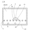
- FIG. 1 is a schematic perspective view schematically showing a salmon breeding apparatus 1A in the first embodiment.
- FIG. 2 is a cross-sectional view of the salmon breeding apparatus 1A, which is a cross-sectional view along a plane PL of FIG.
- the eyelid breeding apparatus 1A in the first embodiment includes a rattan container 2 having a first breeding room SP1 and a support member 3.
- the support member 3 may define a space on the support member 3 in which the bait is disposed and a space below the support member 3 in which the feces are stored.
- the support member 3 since it can be said that the space above the support member 3 and the space below the support member 3 are functionally separated, the support member 3 may be called a partition member.
- the rattan container 2 has a support member 3, a rattan A, and a first breeding room SP1 for housing the bait F.
- the first breeding room SP1 is at least a part of a space defined by the rattan container 2 and is a first direction from the first end 21 of the rattan container 2 to the second end 22 of the rattan container 2. Extend in the direction.
- the angle between the first direction and the horizontal plane is preferably 0 degrees or more and 45 degrees or less, more preferably 0 degrees or more and 20 degrees or less, and still more preferably 0 degrees.
- the angle between the first direction and the horizontal plane is 0 degree
- the first breeding room SP1 is arranged horizontally.
- the angle between the first direction and the horizontal plane is larger than 0 degree, the first breeding room SP1 is arranged to be inclined.
- the first breeding room SP1 is an elongated chamber in which the length in the direction along the first direction is longer than the length in the direction perpendicular to the first direction.
- the length L (the length in the direction along the first direction) of the first breeding room SP1 is, for example, 20 cm or more, 30 cm or more, or 40 cm or more.
- the width W (the length in the width direction perpendicular to the first direction) of the first breeding room SP1 is, for example, 1/2 or less or 1/5 or less of the length L of the first breeding room SP1.
- the height H (the length in the direction perpendicular to both the first direction and the width direction) of the first breeding room SP1 is, for example, 1 ⁇ 5 or less or 1 of the length L of the first breeding room SP1. It is less than / 10.
- the wall member W1 defining the first breeding room SP1 is made of, for example, a resin such as polyethylene terephthalate resin or acrylic resin.
- a resin such as polyethylene terephthalate resin or acrylic resin.
- the said resin is a raw material which can observe inner side from outer side, for example, it is preferable that it is transparent or semi-transparent resin.
- the first breeding room SP1 is preferably open at least at the first end 21.
- a third instar larva eg, first instar larva, second instar larva, third instar larva, fourth instar larva, or fifth instar larva
- the opening 21 a may be used as an opening for inserting the support member 3, or may be used as an opening for taking out the feces of the support member 3 or a cocoon.
- the first breeding room SP1 may be open at the second end 22.
- the first breeding room SP1 has at the second end 22 a takeout opening 22a through which the cocoon or cocoon can be taken out.
- the removal opening 22a may be utilized as an opening for inserting the support member 3, and may be utilized as an opening for taking out the feces of the support member 3 or a cocoon. Needless to say, depending on the position of the pupa (for example, 5th instar larva) or the pupa, these may be taken out from the first breeding room SP1 via the first end 21 (opening 21a).
- the wall member W1 defining the first breeding room SP1 is a cylindrical wall member.
- the wall member W1 defining the first breeding room SP1 is a bottomed cylindrical wall member. In this case, the inlet for inserting the weir A and the outlet for taking out the weir A or weir are the same.
- the support member 3 has a function of supporting the chopsticks A, a function of supporting the bait F, and a function of dropping the feces discharged by the chopsticks A on the support member 3 below the support member 3. For this reason, the support member 3 is provided with an opening OP through which the feces discharged by the sputum can pass. In the example shown in FIG. 1, the support member 3 is provided with 100 or more openings OP. In addition, when the function which drops the droppings which the gutter A on the supporting member 3 discharges to the lower part of the supporting member 3 is unnecessary, the opening OP does not need to be provided in the supporting member 3, and the supporting member 3 is opened. Even if the OP is provided, the shape and size of the opening OP may be such that the feces discharged by the weir A can not pass through.
- the support member 3 is a mesh-like member (in other words, a net-like member), and each opening of the mesh corresponds to the opening OP through which feces can pass.
- the minimum length of the opening OP is, for example, 5 mm or more, 7 mm or more, or 10 mm or more from the viewpoint of making the passage of the feces more reliable, but the shape and size of the feces may differ depending on the type of cocoon It is only necessary that feces can pass through.
- the minimum length corresponds to the diameter of the circle, and when the opening OP is a rectangle, the minimum length corresponds to a rectangular short piece.
- the maximum length of the opening OP is not particularly limited, but the maximum length is, for example, 30 mm or less, 20 mm or less, or 15 mm or less.
- the shapes and / or sizes of the plurality of openings OP may be the same as or different from each other.
- the rattan A inserted into the first breeding room SP1 has a tendency to move to a higher place, generally, from the first end 21 to the second end 22 as it grows It is assumed to move towards.
- basket in 1st breeding room SP1 is free, it does not need to perform the movement which the cage
- the weir A may reciprocate between the first end 21 and the second end 22.
- the upper surface of the support member 3 be disposed to be inclined with respect to the horizontal plane.
- the height (height of the top surface) of the support member 3 at the second end 22 is higher than the height (height of the top surface) of the support member 3 at the first end 21.
- the habit of moving to a higher place has the habit of moving upwards, especially at the stage of growth where the time of the making of the bush is approaching.
- the support member 3 is configured to be inclined with respect to the horizontal plane by arranging the leg 31 on the second end 22 side of the support member 3.
- the leg 31 on the second end 22 side may be made longer than the leg on the first end 21 side.
- the side surface of the wall member W1 may be provided with a protrusion which projects into the first breeding room SP1, and the support member 3 may be supported by the protrusion.
- the support member 3 is inclined to the bottom surface BS of the first breeding room SP1, whereby the support member 3 is inclined to the horizontal surface.
- the support member 3 is the first breeding room SP1. It may be disposed parallel to the bottom surface BS of the.
- the support members 3 are arranged such that the heights in the width W direction of the support members 3 are the same, but the heights in the width W direction of the support members 3 are not necessarily the same. May be Further, in the example shown in FIG.
- the upper surface of the support member 3 is formed in a planar shape, but the invention is not limited thereto.
- the second end 22 from the first end 21 side of the support member 3 There is a tendency that the side is higher or the first end 21 side is higher than the second end 22 side of the support member 3.
- the upper surface of the support member 3 has irregularities or other shapes. It may be done.
- the support member 3 is detachable with respect to the wall member W1 which defines the first breeding room SP1.
- the support member 3 may be supported by the wall member W1.
- the support member 3 can be removed from the wall member W1. In this case, the support member 3 and the wall member W1 can be cleaned independently.
- the support member 3 may be formed by weaving or knitting a thread-like member. Alternatively, the support member 3 may be formed integrally with the crucible container 2 or may be formed by joining a plurality of members.
- the support member 3 may be made of metal, may be made of resin, or may be made of other materials.
- the structure which inclines the support member 3 with respect to the horizontal surface is not an essential structure in embodiment.
- the support member 3 may be disposed parallel to the horizontal plane. In other words, the upper surface of the support member 3 may be substantially horizontal.
- the bait F is disposed, for example, along the longitudinal direction (first direction) of the support member 3.
- first direction the longitudinal direction of the support member 3.
- the weir A disposed on the first end 21 side is along the bait F while feeding the bait F to the second end 22 side. Moving. Accordingly, it becomes easy to take out the weir A or weir from the takeout opening 22a on the second end side.
- feed F is an inclined surface. Since the upper surface of the bait F is an inclined surface, it is difficult for the cocoon feces D (see FIG. 2) to be deposited on the upper part of the bait F. For this reason, the breeding environment of salmon does not deteriorate.
- the shape of the upper surface of the bait F may be any shape such as an inverted V-shape (a shape of a roof), for example, as long as it is a shape in which the droppings D do not easily deposit, that is, a shape in which droppings D are easily dropped. Can be adopted.
- the inclined surface also includes a curved inclined surface.
- the bait F in the cross section perpendicular to the first direction, has a first portion F1 whose height gradually decreases from the highest portion HP toward one side of the highest portion HP, and the highest portion And a second portion F2 whose height gradually decreases from the HP toward the other side of the highest portion HP.
- the bait F may have a semicircular shape in a cross section perpendicular to the first direction.
- the bait F is continuously disposed along the longitudinal direction of the support member 3.
- the bait F may be disposed intermittently along the longitudinal direction of the support member 3.
- the bait F is disposed along a straight line parallel to the longitudinal direction of the support member 3, but the bait F includes a plurality of bait F parallel to the longitudinal direction of the support member 3. It may be arranged along a straight line. Also, the bait F may have a curved portion as long as it extends in the longitudinal direction of the support member 3. In the case where the bait F is arranged in an elongated shape along one or more lines (including a curve), the task of arranging the bait F on the support member 3 is easy. For example, it is also possible to dispose the bait F on the support member 3 by pushing the bait F out of a tube or the like.
- a portion of the support member 3 is exposed without being covered by the bait F (see the exposed portion E).
- an exposed portion E which is exposed without being covered by the bait is arranged on the side of the bait F.
- the exposed portion E may be disposed on the first direction side (or the side opposite to the first direction) than the bait F. Since the rattan A prefers a dry atmosphere, the breeding environment of the rattan is improved by providing the exposed portion E in which no food (wet food) is present. More specifically, the cocoon A can rest at the exposed part E in a dry state than the place where the bait F is. ⁇ A can also spend a sleeping period in the exposed area E. In the example shown in FIG. 1, the area of the exposed portion E of the support member 3 is larger than the area where the support member 3 is covered by the bait F, but it is needless to say that the present invention is not limited thereto. .
- the feed F is, for example, an artificial feed containing mulberry leaves, okara and water.
- the support member 3 for supporting salmon and food has an opening OP through which the feces of salmon can pass. For this reason, the breeding environment of salmon is improved. Furthermore, after the chicks or chicks are taken out from the first breeding room SP1, the work of sorting the chick feces D and chick feed F becomes easy. Duck feces D can be used as feed for other livestock or as a component of medicine.
- FIG. 3 is a schematic perspective view schematically showing a salmon breeding apparatus 1B in the second embodiment.
- the rattan container 2 includes a plurality of breeding rooms SP including the first breeding room SP1 and the second breeding room SP2.
- the salmon breeding apparatus 1B in the second embodiment is the same as the salmon breeding apparatus 1A in the first embodiment.
- the first breeding room SP1 in the second embodiment is the same as the first breeding room SP1 in the first embodiment.
- the first breeding room SP1 is defined by the wall member W1, and in the first breeding room SP1, as in the first embodiment, the support member 3, the bait F, and the chopsticks A are arranged.
- the second breeding room SP2 extends along the first direction.
- the shape of the second breeding room SP2 is preferably the same as the shape of the first breeding room SP1, and the shape and structure of the support member 3 disposed in the second breeding room SP2 are the same as those in the first breeding room SP1. It is preferable that it is the same as the shape and structure of the support member 3 arrange
- the wall member W1 defining the first breeding room SP1 and the wall member W2 defining the second breeding room SP2 are integrally formed. For this reason, the strength of the crucible container 2 is improved. Moreover, it becomes possible to arrange more breeding rooms in the rattan container 2. As shown in FIG. 3, a part WP of the wall member W1 defining the first breeding room SP1 may simultaneously constitute a part WP of the wall member W2 defining the second breeding room SP2.
- the rattan container 2 of the rat breeding apparatus 1B may be configured by arranging the first breeding room SP1 and the second breeding room SP2 separately formed in close contact or in engagement with each other.
- a tubular container defining the first breeding room SP1 and a tubular container defining the second breeding room SP2 are separately prepared, and these tubular containers are inserted into the frame member,
- the crucible container 2 having a plurality of breeding rooms may be formed in a form that can be separated from each other.
- the shapes of the breeding rooms SP other than the first breeding room SP1 and the second breeding room SP2 are preferably the same as the shapes of the first breeding room SP1. Further, it is preferable that the shape and the structure of the support member 3 disposed in the breeding room SP be the same as the shape and the structure of the support member 3 disposed in the first breeding room SP1.
- the eyelid breeding apparatus 1B according to the second embodiment has the same effect as the eyelid breeding apparatus 1A according to the first embodiment.
- the rattan container 2 includes a plurality of breeding rooms SP. For this reason, it is possible to breed many chicks at one time.
- the number of breeding rooms SP provided in the container 2 is, for example, 2 or more and 1000 or less, or 50 or more and 1000 or less.
- the height of the support members 3 at the second end 22 is higher than the height of the support members 3 at the first end 21.
- the plurality of cages arranged in the plurality of breeding rooms SP move upward, that is, toward the second end 22 when the time of making the cages approaches. For this reason, it becomes easy to take out a plurality of folds or wrinkles from the 2nd end 22 side.
- the cross section of the crucible container 2 in a plane perpendicular to the first direction has a repeated shape of the cross-sectional shape including the first breeding room SP1.
- the constituent unit of the repetitive shape is a quadrangular shape (more specifically, a rectangular shape).
- the cross-sectional shape (the cross-sectional shape in the plane perpendicular to the first direction) of the wall member that defines each breeding room SP is a square frame shape.
- the cross section of the crucible container 2 in a plane perpendicular to the first direction has a repeated shape of the cross sectional shape of the first breeding room SP1, but the structural unit of the repeated shape is a quadrangle It is a shape other than the shape.
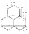
- the building blocks of the repeating shape may be hexagonal as shown in FIG. 4A.
- the cross-sectional shape (the cross-sectional shape in a plane perpendicular to the first direction) of the wall member defining each breeding room SP is a hexagonal frame shape.
- the corner CP is used to support the support member 3 May be
- the building blocks of repeating shapes may be polygonal shapes other than hexagonal shapes, for example triangular shapes as shown in FIG. 4B, and circular shapes as shown in FIG. 4C.
- the cross-sectional shape (the cross-sectional shape in the plane perpendicular to the first direction) of the wall member defining each breeding room SP is a polygonal frame shape (for example, a triangular frame shape) or a ring shape.
- the repeating shaped structural unit may be a rounded polygonal shape with rounded corners.
- angular part of the shape (structural unit of a repeating shape) of each breeding room is rounded, washing
- the corner is pointed, the feces (or dirt) attached to the corner tend to stay in the corner during cleaning.
- the corner is rounded, the feces (or dirt) attached to the corner are easily peeled off at the time of washing.
- the cross-sectional shapes (cross-sectional shapes in the direction perpendicular to the first direction) of all the breeding rooms SP are equal, the breeding environment of the chicks placed in each breeding room is placed in another breeding room. It becomes equivalent to breeding environment.
- the cross-sectional shapes of all the breeding rooms SP do not have to be the same.
- the cross-sectional shape of the first breeding room may be different from the cross-sectional shape of the second breeding room.
- two breeding rooms consisting of a first breeding room and a second breeding room may be structural units of repeated shape.
- three or more breeding rooms may be structural units of repeated shapes.
- FIG. 5 is a schematic perspective view schematically showing a salmon breeding apparatus 1C according to a third embodiment.
- FIG. 6 is a schematic plan view schematically showing a salmon breeding apparatus 1C in the third embodiment.
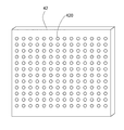
- FIG. 7 is a schematic perspective view schematically showing the first lid member 41, and
- FIG. 8 is a schematic perspective view schematically showing the second lid member 42. As shown in FIG.
- the rat breeding apparatus 1C in the third embodiment includes a first lid member 41 and / or a second lid member 42.
- the first lid member 41 is a member that covers the first end 21 of the crucible container 2
- the second lid member 42 is a member that covers the second end 22 of the crucible container 2.
- each of the first lid member 41 and the second lid member 42 is provided with a plurality of vent holes.
- the shape of each vent may be the same or different.
- the hole diameter of each air vent is preferably a size that can not pass through the weir A, and is, for example, 1 mm or more and 10 mm or less. Alternatively, the area of each vent is 0.5 mm 2 or more and 100 mm 2 or less.
- each air vent is preferably a shape that can not pass the weir A, and may be a circular shape or a non-circular shape such as a polygonal shape.
- the size of the vent 420 provided in the second lid member 42 may be larger or smaller than the size of the vent 410 provided in the first lid member 41, and may be the same.
- the first lid member 41 can cover the first end 21 of the crucible container 2 and can open the first end 21 of the crucible container 2. With the first end 21 of the rattan container 2 opened, a plurality of rattans are respectively inserted into a plurality of breeding rooms SP. After the plurality of rattan are inserted into the plurality of breeding rooms SP, the first end 21 of the rattan container 2 is covered by the first lid member 41.
- the first lid member 41 is a slide type lid member.
- the rat breeding apparatus 1 ⁇ / b> C includes the frame member 50 surrounding the crucible container 2, and the frame member 50 is provided with the sliding guide portion 51.
- the first lid member 41 is slidably movable with respect to the sliding guide portion 51.
- the first lid member 41 is completely separable from the frame member 50. Therefore, the cleaning of the first lid member 41 can be easily performed.
- the first lid member 41 may be a lid member other than a slide type, and for example, the first lid member 41 is provided on the frame member 50 and can be opened and closed with respect to the first end 21 of the crucible container 2 (for example, It may be swingable), or may be configured to act as a lid member by other means.
- the second lid member 42 can cover the second end 22 of the crucible container 2 and can open the second end 22 of the crucible container 2. With the second end 22 of the crucible container 2 open, the crucible or crucible can be removed from the crucible container 2. On the other hand, in a state where the second end 22 of the crucible container 2 is covered by the second lid member 42, the crucible is formed from the second end 22 side by making the size of the vent 420 smaller than the size of the crucible. I can not get out of the container.
- the second lid member 42 is a slide type lid member.
- the sliding guide portion 52 is provided on the frame member 50.
- the second lid member 42 is slidably movable relative to the sliding guide portion 52.
- the second lid member 42 is completely separable from the frame member 50. Therefore, the second lid member 42 can be easily cleaned.
- the second lid member 42 may be a lid member other than a slide type.
- the second lid member 42 is provided on the frame member 50 and can be opened and closed with respect to the second end 22 of the crucible container 2 (for example, It may be swingable), or may be configured to act as a lid member by other means.
- the eyelid breeding apparatus 1C according to the third embodiment exhibits the same effect as the eyelid breeding apparatus 1B according to the second embodiment.
- the salmon breeding apparatus 1C according to the third embodiment includes a first lid member 41 covering the first end 21 of the salmon container 2 and / or a second lid member 42 covering the second end 22 of the salmon container 2. Prepare. For this reason, the insertion of the crucible into the crucible container 2 and / or the removal of the crucible or the crucible from the crucible container 2 is easy. In addition, the dropping of the bag or the bag from the bag container 2 is effectively suppressed.
- the first lid member 41 is preferably a member that collectively covers the openings on the first end 21 side of the plurality of breeding rooms SP (more preferably, all breeding rooms SP), and the second lid member 42 is It is preferable that it is a member which covers the extraction opening by the side of the 2nd end 22 of a plurality of breeding rooms SP (more preferably, all breeding rooms SP) collectively. In this case, the work of covering the openings of the plurality of breeding rooms SP becomes easy.
- the frame member 50 and the crucible container 2 may be integral or separate.
- manufacture of the frame member 50 and the crucible container 2 becomes easy.
- crucible container 2 is completely separable from the frame member 50, cleaning of the crucible container 2 becomes easy.
- a lid member capable of covering an open portion of the breeding room (the first breeding room SP1 or the like) is provided. May be
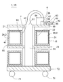
- FIG. 9 is a schematic vertical sectional view schematically showing a salmon breeding apparatus 1D in the fourth embodiment.
- a dry air supply device 6 is added to the eyelid breeding apparatus 1B according to the second embodiment or the eyelid breeding apparatus 1C according to the third embodiment.
- the second end 22 of the crucible container 2 is disposed facing the flow path 60 of the dry air supplied from the dry air supply device 6.
- the air outlet 61 of the dry air supply device 6 is disposed on the second end 22 side of the crucible container 2.
- the 5th instar larvae of silkworms have the habit of moving in search of a dry place. For this reason, in the example shown in FIG. 9, when dry air is supplied to the flow path 60, a plurality of weirs in the weir container 2 gather on the second end 22 side. Therefore, it is possible to easily take out the chopsticks or the cocoon from each breeding room through the removal opening on the second end 22 side of each breeding room SP.
- the dry air supply device 6 includes, for example, an air suction unit 62, a dehumidifying unit 63, and a blower 64. Further, the air suction portion 62 may be provided with a filter 65 for preventing suction of foreign matter and the like. As the air suction part 62, the dehumidification part 63, and the blower 64, it is possible to employ
- the dry air supply device 6 may have a function of supplying humidified air, as needed.
- the dry air supply device 6 preferably includes a valve device 66 that switches the air sent to the air outlet 61 to dry air or humidified air.
- the valve device 66 may be configured by one valve (for example, a three-way switching valve) or may be configured by a plurality of valves.
- a dry air supply pipe 67 and a humidified air supply pipe 68 are connected to the valve device 66.
- a humidifying unit 69 for example, a known humidifying unit that humidifies the sterilized air by introducing it into water
- the dry air supply device 6 When the dry air supply device 6 has a function of supplying humidified air, if humidified air is supplied from the air outlet 61 toward the flow path 60, the humidified air is supplied from the second end 22 side of each breeding room SP. It is introduced into the rattan container 2 and the drying of the bait is suppressed. Also, in order to easily take out firewood from each breeding room, it is sufficient to supply dry air to the firewood that is close to the time of making firewood. For this reason, the supply of the humidified air by the dry air supply device 6 may be switched to the supply of the dry air at a time close to the time when the cocoon makes the cocoon, regardless of whether the humidified air is supplied immediately before or not.
- the dry air may be controlled to be supplied at a time close to the time when the cocoons make a cocoon. Furthermore, in the control of the supply timing of the dry air, the drying container 6 is installed with the drying air supply device 6 as will be described later, when it becomes a time close to the time when the rattan inside the breeding room makes a rattan. It is also included to supply dry air to the second end 22 side of each breeding room SP of the container 2 by moving it to the location where it is located.
- the rat breeding apparatus 1D may include a container support member 7 for supporting one or more crucible containers 2 and a caster 71 provided at the bottom of the container support member 7.
- the container support member 7 includes a lower portion 72 supporting the crucible container 2 and an upper portion 73 supporting the crucible container 2.
- the crucible containers 2 are arrange
- a plurality of crucible containers 2 may be supported by the lower portion 72, and a plurality of crucible containers 2 may be supported by the upper portion 73.
- the crucible containers 2 are arranged in two stages, but the crucible containers 2 may be arranged in one stage or three or more stages.
- the salmon breeding apparatus 1D includes the caster 71, the arrangement of the plurality of salmon containers 2 in the salmon breeding facility can be easily changed. For this reason, the accumulation degree of the cane container 2 in cane breeding equipment can be improved.
- the dry air supply device 6 is fixed to a breeding facility (such as a building)
- the cane container 2 may be disposed close to the dry air supply device 6 or dry air according to the growth rate of the chicks. It becomes possible to separate from the supply device 6 or the like.
- two crucible containers (2A, 2B) are disposed so as to sandwich the flow path 60 (flow path of dry air). For this reason, it is possible to supply dry air to more crucible containers using one flow passage 60. More specifically, in the example shown in FIG. 9, the second end 22 of the first crucible container 2A faces the flow passage 60 (facing the flow passage 60 via the second lid member 42), and The second end 22 of the second crucible container 2B faces the flow passage 60 (facing the flow passage 60 through the second lid member 42), and the second end 22 of the first crucible container 2A and the second crucible The second end 22 of the container 2B is disposed to face each other.
- the dry air supply device 6 is attached to the container support member 7, but the dry air supply device 6 is attached to a member other than the container support member that supports the crucible container 2. It is also good.
- the dry air supply device 6 may be attached to the ceiling of the silkworm breeding facility.
- the dry air supply device 6 supplies dry air from top to bottom, but alternatively, the dry air supply device 6 supplies dry air in the horizontal direction. You may do it. In other words, instead of arranging the channels 60 in the vertical direction, they may be arranged in the horizontal direction.
- the eyelid breeding apparatus 1D according to the fourth embodiment has the same effect as the eyelid breeding apparatus 1B according to the second embodiment or the eyelid breeding apparatus 1C according to the third embodiment.
- the salmon breeding apparatus 1D in the fourth embodiment includes a dry air supply device 6 that supplies dry air to the second end 22 of the salmon container 2. Therefore, the crucible or the crucible can be collected on the second end 22 side of the crucible container 2 separately from the fact that the shape of the support member 3 induces the movement of the crucible. As a result, it becomes easy to collect the sputum or sputum.
- the rat breeding apparatus 1D includes a breeding room in which one crucible is placed, a wicker container 2 including a plurality of the breeding rooms, and a container support member 7 on which the plurality of wicker containers 2 are placed.
- a breeding room in which one crucible is placed
- a wicker container 2 including a plurality of the breeding rooms
- a container support member 7 on which the plurality of wicker containers 2 are placed.
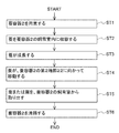
- FIG. 10 is a flow chart showing an example of a method of rearing salmon according to the embodiment.
- the chick breeding method in the embodiment is performed using the chick breeding apparatus 1 in any of the above-described embodiments.
- a rattan container 2 provided with at least one breeding room (for example, the first breeding room SP1) is prepared.
- the support member 3 and the bait F are disposed.
- the cocoon A is housed in the first breeding room SP1.
- the accommodation is performed, for example, by transferring the crucible A onto the support member 3.
- the cocoon A accommodated in the first breeding room SP1 is, for example, from a larva immediately after hatching (first instar larva) to a fourth instar larva.
- the first breeding room SP1 may store eggs of moth instead of containing moth A.
- each breeding room for example, the first breeding room SP1
- each breeding room for example, the first breeding room from the side of the first end 21. It is done by inserting in the breeding room).
- the rat breeding apparatus 1 includes the first lid member 41
- the first end 21 of the rattan container 2 is covered by the first lid member 41 after the rattan A is inserted into each breeding room.
- the salmon breeding apparatus 1 includes the second lid member 42
- the second end 22 of the salmon container 2 is covered by the second lid member 42.
- the process of covering the second end 22 with the second lid member 42 may be performed before the second step ST2 or may be performed after the second step ST2.
- the second step ST2 may be performed in a state where the rattan container 2 is placed on the container support member 7.
- the crucible container 2 may be placed on the container support member 7 after performing the second step ST2.
- the larvae from the first instar larva to the third instar larva are different from the weir container 2 in the embodiment.
- the cocoon A of the third instar larva is inserted and accommodated in the first breeding room SP1.
- the cocoon container 2 when the cocoon container 2 is provided with a plurality of breeding rooms, it is preferable that only one cocoon (for example, third instar larvae) is inserted into each breeding room.
- a dedicated breeding room individual room
- each cage A By providing a dedicated breeding room (individual room) for each cage A, the stress acting on the cage A is greatly reduced. As a result, it is expected that hemorrhoids will grow healthier and larger.
- the brow A grows by eating the bait F on the support member 3.
- the silkworm A digests the feed F to excrete it.
- the feces fall below the support member 3. Therefore, the breeding environment of salmon A does not deteriorate.
- a plurality of vent holes 410 are provided in the first lid member 41, and a plurality of vent holes 420 are provided in the second lid member 42. For this reason, even if the first lid member 41 covers the first end 21 of the crucible container 2 and the second lid member 42 covers the second end 22 of the crucible container 2, The air is introduced from the outside of the crucible container 2.
- the humidified air is supplied into the crucible container 2 in the third step ST3.
- the drying of the bait F is suppressed and the humidity in the container is maintained at a humidity suitable for the growth of the container.
- the humidified air supplied from the dry air supply device 6 is supplied into the crucible container 2 through, for example, the plurality of vent holes 420 of the second lid member 42. And the pressure in the crucible container 2 becomes positive pressure.
- the air in the crucible container 2 is discharged through the plurality of vent holes 410 of the first lid member 41.
- the weir A in each breeding room moves toward the second end 22 of the weir container 2.
- the movement may be induced by the bait F extending from the first end 21 toward the second end 22, or as the upper surface of the support member 3 is directed to the second end 22. It may be attracted by being arranged to become high.
- the salmon breeding apparatus 1 includes the dry air supply device 6, the movement toward the second end 22 of the salmon is induced by supplying the dry air to the second end 22.
- the dry air supplied from the dry air supply device 6 is supplied into the crucible container 2 through, for example, the plurality of vent holes 420 of the second lid member 42. And the pressure in the crucible container 2 becomes positive pressure.
- the air in the crucible container 2 is discharged through the plurality of vent holes 410 of the first lid member 41.
- chicks for example, fifth-instar larvae
- chicks are taken out from each breeding room (for example, first breeding room SP1).
- the chicks are transferred to an environment for producing chicks.
- the chicks make chicks in each breeding room, they are taken out of each breeding room in the fifth step ST5.
- the cocoon may be formed in a state in which the cocoon adheres to the wall member (cylindrical wall member) defining each breeding room, or may be formed in a state in which the cocoon adheres to the second lid member 42 , And the second cover member 42 may be formed in a state in which wrinkles adhere to both the wall member and the second cover member 42.
- the second lid member 42 is removed from the second end of the crucible container 2 before the fifth step ST5 is performed.
- the second lid member 42 may be completely separated from the crucible container 2.
- step ST4 since the eyelids move toward the second end 22 side, in the fifth step ST5, it is easy to take out the eyelids or eyelids from the second end 22 side.
- the fifth step ST5 may be performed after moving the cocoon container 2 from the cocoon rearing area to the cocoon removal work area.
- the movement of the cocoon container 2 is performed, for example, using a caster 71 provided in the cocoon breeding apparatus 1.
- the crucible container 2 is cleaned.
- the bait is disposed on the support member 3, and the cocoon feces is disposed below the support member 3. Therefore, it is easy to collect pupa feces.
- Duck feces can be used as feed for other livestock or as a component of medicine.
- the cleaning operation for example, the cleaning operation
- the cleaning operation of the crucible container 2 is easy.
- air or water is sprayed from the first end 21 (or the second end 22) of the crucible container 2, and unwanted matter is discharged from the second end 22 (or the first end 21) of the crucible container 2.
- water is drained.
- the support member 3, the first lid member 41 and the second lid member 42 can be completely separated from the crucible container 2, the cleaning operation of the support member 3, the first lid member 41 and the second lid member 42 is performed. (For example, cleaning operation) is easy.
- the cage arranged in the first breeding room SP1 is a cage of the 5th instar larva, it is not necessary to arrange the feed F in the first breeding room SP1. That is, in the case where the sufficiently grown salmon is disposed in the first breeding room SP1, it is not necessary to further enlarge the salmon. For this reason, in the first step ST1 described above, the food F need not necessarily be disposed in the first breeding room SP1.
- the cage arranged in the first breeding room SP1 is a cage of the 5th instar larva.
- the use of the single-chamber cocoon container 2 is limited to the cocoon of the 5th instar larva, the period in which the single room is occupied by one cocoon is further shortened.
- the period in which the chicks occupy the breeding room SP is shortened from 10 days to 5 days, the first chick is reared in the breeding room SP in the first 5 days, and the second five days thereafter. It becomes possible to breed the chicks in the breeding room SP. Therefore, the total number of the breeding rooms SP required to breed a predetermined number of chicks can be halved. When rearing salmon individually, the number of breeding rooms greatly affects the breeding cost. In the rat breeding method according to the modification, it is possible to reduce the number of breeding rooms by improving the use rotation rate of the breeding room. In this case, breeding costs are significantly reduced.
- the step of arranging the bait F in the first breeding room SP1 can be omitted. For this reason, the breeding cost of salmon is further reduced. Further, since the bait F does not adhere to the wall surface of the support member 3 or the first breeding room SP1, the step of cleaning the support member 3 and / or the rattan container 2 (the sixth step ST6 described above) can be performed more easily. Is possible.
- the above-mentioned points except that the cage of the 5th instar larva is arranged in the first breeding room SP1 and the point that the bait F is not arranged in the first breeding room SP1 The method is the same as the method for raising salmon (first step ST1 to sixth step ST6). Therefore, the description which becomes repetition about the matter already demonstrated in the above-mentioned cocoon breeding method (1st step ST1 thru
- the salmon breeding apparatus 1 used in the salmon breeding method further includes a manipulator 8 provided with a gripping unit 82 that grips the salmon A.
- the salmon breeding apparatus 1 may have a support member insertion device 9.
- the components other than the manipulator 8 and the support member insertion device 9 of the salmon breeding apparatus 1 are the salmon breeding apparatus 1A in the first embodiment, the salmon breeding apparatus 1B in the second embodiment, and the salmon breeding in the third embodiment It is the same as the apparatus 1C or the salmon breeding apparatus 1D in the fourth embodiment. Therefore, the repeated description of these components is omitted.
- the weir placement step includes the weir transfer step of transferring the weir A onto the support member 3 by the manipulator 8.
- the weir transfer step of transferring the weir A onto the support member 3 by the manipulator 8.
- at least a part of the support member 3 is disposed outside the first breeding room SP1.
- one mouse is placed on each support member 3 from a first container C (for example, a container whose upper side is open or a tray whose upper side is open) containing a plurality of bases. It is preferable to be transferred.
- the crucible arrangement step includes a support member insertion step of inserting the support member 3 to which the crucible A has been transferred into the first breeding room SP1.
- the support member 3 and the tub A are disposed in the first breeding room SP1.
- the insertion of the support member 3 into the first breeding room SP1 is performed using a support member insertion device 9 different from the manipulator 8.
- the support member insertion device 9 is, for example, a conveyor 90 (for example, a conveyor 90 provided with a pusher 91 for pressing the support member 3).
- the manipulator 8 may function as the support member insertion device 9. In other words, the manipulator 8 may push the support member 3 into the first breeding room SP1. In this case, the conveyor 90 in FIG. 11 can be omitted.
- the salmon breeding apparatus 1 includes the manipulator 8 including the gripping portion 82 that grips the salmon A and the support member insertion device 9.
- the work of inserting the rattan A into the breeding room SP can be automated. Since no worker intervenes in the work of inserting the crucible A into the breeding room SP, the risk of contamination of bacteria in the breeding room SP is reduced. Automation also reduces the cost of raising chicks.
- the rattan container 2 has a plurality of breeding rooms SP including a first breeding room SP1 and a second breeding room SP2.
- the first transfer / transfer step of transferring the first weir A1 to the support member 3 by the manipulator 8 and the support member 3-1 on which the first weir A1 has been transferred
- a second transfer transfer step of transferring the second weir A2 to the second support member 3-2 by the manipulator 8 (FIG.
- the second support member insertion step of inserting the second support member 3-2 to which the second weir A2 has been transferred into the second breeding room SP2 see FIG.
- the crucible arrangement step is performed by the manipulator 8 using the K-th support member 3-K. Transfer step of transferring the K-th cage to the K-th support member, and K-th support member insertion step of inserting the K-th support member 3-K to which the K-th cage is transferred into the K-th breeding room May be included.
- the insertion of the first support member 3-1 into the first breeding room SP1 and the insertion of the second support member 3-2 into the second breeding room SP2 At the same time.
- the second support member 3-2 may be inserted into the second breeding room SP2.
- the bait F is not disposed on each support member 3.
- the support member 3 in which the feed F and the meal A are disposed may be inserted into a breeding room such as the first breeding room SP1.
- the support member 3 is inserted into the breeding room such as the first breeding room SP1 through the opening of the first end 21 of the crucible container 2.
- the support member 3 may be inserted into a breeding room such as the first breeding room SP1 through the opening of the second end 22 of the crucible container 2.
- the crucible arrangement process described in FIG. 12 differs from the crucible arrangement process described in FIG. 11 in that the crucible A is transferred to the support member 3 in the first breeding room SP1.
- the crucible placement step includes a tray transfer step of transferring the crucible A to the support member 3 in the first breeding room SP1 by the manipulator 8.
- the transfer of the crucible A by the manipulator 8 is performed through the opening of the first end 21 of the crucible container 2 (or the opening of the second end 22).
- the pot transfer process from the first container C containing a plurality of pots (for example, a container whose upper side is opened or a tray whose upper side is opened), 1 on the support member 3 in each breeding room SP It is preferred that only individual bales be transferred.
- the salmon breeding apparatus 1 includes a manipulator 8 provided with a gripping portion 82 that grips the salmon A.
- the work of inserting the rattan A into the breeding room SP can be automated. Since no worker intervenes in the work of inserting the crucible A into the breeding room SP, the risk of contamination of bacteria in the breeding room SP is reduced. Automation also reduces the cost of raising chicks.
- the rattan container 2 has a plurality of breeding rooms SP including a first breeding room SP1 and a second breeding room SP2.
- the rod placement step is performed by the manipulator 8
- a second transfer / transfer process may be performed to transfer the second crucible A2 to the support member 3-2 in the second breeding room SP2.
- the chopstick placement step is performed by the manipulator 8 to support the K-th breeding room It may have a K transfer transfer step of transferring the K-th bottle to 3-K.
- the bait F is not disposed on each support member 3.
- the chopsticks A may be transferred to the support member 3 on which the bait F is disposed.
- the manipulator 8 has an arm 81 and a grip 82.
- the arm unit 81 is, for example, a robot arm including one or more joints.
- the gripping portion 82 includes, for example, a plurality of gripping pieces 820 including a first gripping piece 820a and a second gripping piece 820b.
- the number of gripping pieces 820 included in the gripping portion 82 may be two, or three or more.
- the contact portion 821 in contact with the hook of the grip piece 820 is formed of an elastically deformable member (elastic member).
- the contact portion 821 is formed of, for example, silicone rubber. By forming the contact portion 821 with an elastic material (for example, silicone rubber), it becomes possible to preferably hold the chewing that changes in shape and moves.
- the grip piece 820 may be, for example, a grip piece having an internal space P surrounded by an elastic material.
- the gripping piece 820 can be driven by supplying a fluid such as air to the internal space P.
- each gripping piece 820 includes a fluid supply path PH that supplies fluid to the internal space P.
- the method disclosed by international publication 2012/148742 may be employ
- the crucible container 2 and / or the container support member 7 may be placed in a sterile facility in a building, or in a sterile facility in a cavity surrounded by soil (eg in a tunnel) It is also good. If the container 2 and / or the container support 7 is arranged in a sterile installation in a cavity surrounded by soil, the construction costs of the building can be omitted. In addition, since the temperature and humidity are substantially constant in the cavity surrounded by the soil, the energy (for example, the energy required for air conditioning) for realizing the breeding environment of the rattan is greatly reduced. Furthermore, since the inside of the cavity surrounded by the soil has high sound insulation and vibration resistance, the deterioration of the breeding environment of salmon due to noise, vibration and the like is suppressed.
- the first cylindrical container defining the first breeding room SP1 may be a bottomed cylindrical container in which only the first end 21 is opened and the second end 22 is closed.
- the first cylindrical container defining the first breeding room SP1 is a tubular cylindrical container in which both the first end 21 and the second end 22 are open (in other words, a tubular cylinder). Container may be used.
- Dehumidification part 64 ... Blower, 65 ... Filter, 66 ... Valve device, 67 ... Dry air supply piping, 68 ... Humidified air supply piping, 69 ... Humidification part, 71 ... Castor, 72 ...
Abstract
蚕飼育装置は、第1飼育室を有する蚕容器と、蚕を支持可能な支持部材とを具備する。第1飼育室は、蚕容器の第1端部から蚕容器の第2端部に向かう方向である第1方向に延在する。支持部材は、第1飼育室に配置され、かつ、蚕が排出する糞が通過可能な開口を有する。
Description
本発明は、蚕飼育装置、および、蚕飼育方法に関する。
蚕を飼育するための蚕飼育容器が知られている。蚕飼育容器内には、少なくとも蚕および餌が収容される。蚕飼育容器内の蚕は、蚕飼育容器内の餌を食べて成長する。
蚕を飼育する場合、一般的には、桑の葉等の餌を、毎日(蚕の眠期を除く)、蚕飼育容器に供給する必要がある。蚕の幼虫期は約25日であり、幼虫期に4回脱皮する。そして、蚕は、最終齢の5齢期に、体内で絹蛋白を合成して、約1200mの糸を吐き、当該糸によって繭を作る。
関連する技術として、特許文献1には、養蚕方法が記載されている。特許文献1に記載の養蚕方法では、平板状のパレットにシート状の養蚕用飼料が敷かれ、その上にネットが配設される。ネットは、蚕が脱皮をするときに掴まるために利用される。
特許文献1に記載の養蚕方法では、ネットの下部に、餌と蚕とが配置される。このため、餌と蚕の糞とが混在することとなる。餌と糞とが混在することにより、蚕がそのような餌を食べなくなる等、蚕の飼育環境が悪化する。
そこで、本発明の目的は、蚕の飼育環境を改善することが可能な蚕飼育装置および蚕飼育方法を提供することである。
いくつかの実施形態における蚕飼育装置は、第1飼育室を有する蚕容器と、蚕を支持可能な支持部材とを具備する。前記第1飼育室は、前記蚕容器の第1端部から前記蚕容器の第2端部に向かう方向である第1方向に延在する。前記支持部材は、前記第1飼育室に配置され、かつ、開口を有する。
いくつかの実施形態における蚕飼育方法は、蚕飼育装置を用いた蚕飼育方法である。前記蚕飼育装置は、第1飼育室を有する蚕容器と、前記第1飼育室に配置される支持部材とを具備する。蚕飼育方法は、蚕を前記第1飼育室内に配置する蚕配置工程と、前記蚕が排出する糞を、前記支持部材の下に落下させる工程と、前記蚕または前記蚕によって作られる繭を前記第1飼育室から取り出す工程とを具備する。
本発明により、蚕の飼育環境を改善することが可能な蚕飼育装置および蚕飼育方法を提供することができる。なお、本発明のその他の効果は、発明を実施する形態にて明らかにされる。
以下、実施形態における蚕飼育装置1および蚕飼育方法に関して、添付図面を参照して説明する。なお、以下の説明において、同じ機能を有する部材、部位については、同一の符号が付され、同一の符号が付されている部材、部位について、繰り返しの説明は省略される。
(方向の定義)
本明細書において、蚕容器2の第1端部21から第2端部22に向かう方向を「第1方向」と定義する。
本明細書において、蚕容器2の第1端部21から第2端部22に向かう方向を「第1方向」と定義する。
(第1の実施形態)
図1を参照して、第1の実施形態における蚕飼育装置1Aについて説明する。図1は、第1の実施形態における蚕飼育装置1Aを模式的に示す概略斜視図である。図2は、蚕飼育装置1Aの断面図であって、図1の面PLにおける断面図である。
図1を参照して、第1の実施形態における蚕飼育装置1Aについて説明する。図1は、第1の実施形態における蚕飼育装置1Aを模式的に示す概略斜視図である。図2は、蚕飼育装置1Aの断面図であって、図1の面PLにおける断面図である。
第1の実施形態における蚕飼育装置1Aは、第1飼育室SP1を有する蚕容器2と、支持部材3とを具備する。なお、後述のとおり、支持部材3によって、餌が配置される支持部材3上の空間と、糞が収容される支持部材3よりも下側の空間とが規定される場合がある。この場合、支持部材3は、支持部材3上の空間と支持部材3下の空間とを、機能的に分離していると言えるため、当該支持部材3のことを仕切り部材と呼んでもよい。
(蚕容器2および第1飼育室SP1)
蚕容器2は、支持部材3、蚕A、および、餌Fを収容するための第1飼育室SP1を有する。第1飼育室SP1は、蚕容器2で規定される空間の少なくとも一部であって、蚕容器2の第1端部21から前記蚕容器2の第2端部22に向かう方向である第1方向に延在する。
蚕容器2は、支持部材3、蚕A、および、餌Fを収容するための第1飼育室SP1を有する。第1飼育室SP1は、蚕容器2で規定される空間の少なくとも一部であって、蚕容器2の第1端部21から前記蚕容器2の第2端部22に向かう方向である第1方向に延在する。
第1方向と水平面との間のなす角度は、好ましくは、0度以上45度以下、より好ましくは、0度以上20度以下、更により好ましくは、0度である。第1方向と水平面との間のなす角度が0度である場合、第1飼育室SP1は、水平に配置されることとなる。他方、第1方向と水平面との間のなす角度が0度より大きい場合、第1飼育室SP1は、傾斜して配置されることとなる。
図1に記載の例では、第1飼育室SP1は、第1方向に沿う方向の長さが、第1方向に垂直な任意の方向に沿う方向の長さよりも長い細長い室である。第1飼育室SP1の長さL(第1方向に沿う方向の長さ)は、例えば、20cm以上、30cm以上、あるいは、40cm以上である。また、第1飼育室SP1の幅W(第1方向に垂直な幅方向における長さ)は、例えば、第1飼育室SP1の長さLの1/2以下、あるいは、1/5以下である。また、第1飼育室SP1の高さH(第1方向および幅方向の両方に垂直な方向における長さ)は、例えば、第1飼育室SP1の長さLの1/5以下、あるいは、1/10以下である。
第1飼育室SP1を規定する壁部材W1は、例えば、ポリエチレンテレフタレート樹脂、アクリル樹脂等の樹脂によって構成される。なお、当該樹脂は、外側から内側を観察できる素材であることが好ましく、例えば、透明又は半透明な樹脂であることが好ましい。
第1飼育室SP1は、少なくとも第1端部21において開放されていることが好ましい。この場合、蚕(例えば、1齢幼虫、2齢幼虫、3齢幼虫、4齢幼虫、あるいは、5齢幼虫)、より好ましくは、蚕の3齢幼虫を、第1端部21の開口21aを介して、第1飼育室SP1内に容易に配置することが可能となる。なお、開口21aは、支持部材3を挿入するための開口として利用されてもよく、また、支持部材3または蚕の糞を取り出すための開口として利用されてもよい。
第1飼育室SP1は、第2端部22において開放されていてもよい。この場合、第1飼育室SP1は、第2端部22に、蚕または繭を取り出すことができる取出開口22aを有することとなる。このため、蚕(例えば、5齢幼虫)または繭を、第2端部22(取出開口22a)を介して、第1飼育室SP1から容易に取り出すことが可能となる。なお、取出開口22aは、支持部材3を挿入するための開口として利用されてもよく、また、支持部材3または蚕の糞を取り出すための開口として利用されてもよい。なお、蚕(例えば、5齢幼虫)または繭の位置によっては、これらを、第1端部21(開口21a)を介して、第1飼育室SP1から取り出してよいことは、いうまでもない。
第1飼育室SP1の両端が開放されている場合、第1飼育室SP1を規定する壁部材W1は、筒状の壁部材となる。他方、第1飼育室SP1の一端のみ開放されている場合、第1飼育室SP1を規定する壁部材W1は、有底筒状の壁部材となる。この場合、蚕Aを挿入する入口と、蚕Aまたは繭を取り出す出口とが同じになる。
(支持部材3)
支持部材3は、蚕Aを支持する機能と、餌Fを支持する機能と、支持部材3上の蚕Aが排出する糞を、支持部材3の下方に落下させる機能とを有する。このため、支持部材3には、蚕が排出する糞が通過可能な開口OPが設けられる。図1に記載の例では、支持部材3は、100個以上の開口OPを備える。なお、支持部材3上の蚕Aが排出する糞を支持部材3の下方に落下させる機能が不要である場合には、支持部材3に開口OPが設けられなくてもよく、支持部材3に開口OPが設けられたとしても、開口OPの形状やサイズは、蚕Aが排出する糞が通過不能なものであってよい。
支持部材3は、蚕Aを支持する機能と、餌Fを支持する機能と、支持部材3上の蚕Aが排出する糞を、支持部材3の下方に落下させる機能とを有する。このため、支持部材3には、蚕が排出する糞が通過可能な開口OPが設けられる。図1に記載の例では、支持部材3は、100個以上の開口OPを備える。なお、支持部材3上の蚕Aが排出する糞を支持部材3の下方に落下させる機能が不要である場合には、支持部材3に開口OPが設けられなくてもよく、支持部材3に開口OPが設けられたとしても、開口OPの形状やサイズは、蚕Aが排出する糞が通過不能なものであってよい。
図1に記載の例では、第1飼育室SP1の両端が開放されている場合を想定している。支持部材3は、メッシュ状の部材(換言すれば、網状の部材)であり、メッシュの各開口が、糞が通過可能な開口OPに対応する。糞の通過をより確実にする観点から、開口OPの最小長さは、例えば、5mm以上、7mm以上、あるいは、10mm以上であるが、蚕の種類によって、糞の形状やサイズが異なり得るから、糞が通過可能でありさえすればよい。なお、開口OPが円である場合には、最小長さは、円の直径に対応し、開口OPが長方形である場合には、最小長さは、長方形の短片に対応する。開口OPの最大長さに特に制限はないが、当該最大長さは、例えば、30mm以下、20mm以下、あるいは、15mm以下である。なお、複数の開口OPの形状および/または大きさは、互いに同一であってもよいし、異なっていてもよい。
図1に記載の例では、第1飼育室SP1に挿入された蚕Aは、より高い場所へ移動する習性があるため、成長するにつれて、概ね、第1端部21から第2端部22に向かって移動することが想定されている。なお、第1飼育室SP1内における蚕の移動は自由であるため、蚕Aが想定された移動を行わなくても構わない。例えば、蚕Aが、第1端部21と第2端部22との間を往復移動してもよい。
支持部材3の上面は、水平面に対して傾斜して配置されることが好ましい。図1に記載の例では、第2端部22における支持部材3の高さ(上面の高さ)は、第1端部21における支持部材3の高さ(上面の高さ)よりも高い。蚕は、より高い場所へ移動する習性があるので、特に、繭づくりの時期が近づくような成長の段階に至ると、上方に向かって移動する習性を持つ。このため、支持部材3の高さが第2端部22に向かうにつれて高くなるように支持部材3を配置することにより、蚕が、第2端部22側に向かって移動することが期待できる。よって、蚕が繭を作る場所が自ずと一定の範囲に収まることが期待できるので、第2端部側の取出開口22aから、蚕または繭を取り出すことが容易となる。
図1に記載の例では、支持部材3の第2端部22側に脚部31を配置することにより、支持部材3が水平面に対して傾斜するように構成される。支持部材3の第1端部21側にも脚部を配置する場合には、第2端部22側の脚部31を第1端部21側の脚部よりも長くすればよい。代替的に、壁部材W1の側面に、第1飼育室SP1内に突出する突出部を設け、当該突出部により、支持部材3を支持してもよい。
図1に記載の例では、支持部材3が、第1飼育室SP1の底面BSに対して傾斜配置されることにより、支持部材3が水平面に対して傾斜配置される。他方、第1飼育室SP1の底面BSが水平面に対して傾斜配置される場合(例えば、蚕容器2が水平面に対して傾斜配置される場合)には、支持部材3は、第1飼育室SP1の底面BSに対して平行に配置されてもよい。図1に記載の例では、支持部材3の幅W方向の高さが同じになるように支持部材3が配置されているが、支持部材3の幅W方向の高さは、必ずしも同じでなくてもよい。また、図1に記載の例では、支持部材3の上面は、平面状に形成されているが、これに限られず、全体として、支持部材3の第1端部21側より第2端部22側が高いという傾向または支持部材3の第2端部22側より第1端部21側が高いという傾向があればよく、例えば、支持部材3の上面は、凹凸が存在したり、その他の形状を有していてもよい。なお、支持部材3の上面を、水平面に対して傾斜して配置することは必須の構成ではない。換言すれば、支持部材3の上面は、非傾斜面であっても構わない。
支持部材3は、第1飼育室SP1を規定する壁部材W1に対して着脱自在であることが好ましい。この場合、支持部材3上に餌Fを配置した後に、支持部材3を壁部材W1に支持させればよい。また、蚕または繭を第1飼育室SP1から取り出した後に、支持部材3を壁部材W1から取り外すことが可能である。この場合、支持部材3および壁部材W1を独立して洗浄することが可能である。
支持部材3は、糸状の部材を織ったり、編んだりすることにより形成してもよい。代替的に、支持部材3は、蚕容器2と一体成形により形成されてもよいし、複数の部材を接合することにより形成されてもよい。支持部材3は、金属製であってもよいし、樹脂製であってもよいし、その他の材料によって構成されていてもよい。
図1に記載の例では、第1飼育室SP1の両端が開放されている場合(より具体的には、第1端部21に開口21aが設けられ、第2端部22に取出開口22aが設けられる場合)が想定されている。他方、第1飼育室SP1の一方端のみが開放され、第1飼育室SP1の他方端が開放されていない場合(他方端に開口が設けられていない場合)には、支持部材3は、開放された一方端に向かうにつれて支持部材3の高さ(上面の高さ)が高くなるように配置されてもよい。
なお、支持部材3を水平面に対して傾斜配置する構成は、実施形態において必須の構成ではない。支持部材3は、水平面に対して平行に配置されてもよい。換言すれば、支持部材3の上面は、実質的に水平であってもよい。
(餌F)
餌Fは、例えば、支持部材3の長手方向(第1方向)に沿って配置される。餌Fが、支持部材3の長手方向に沿って配置される場合、第1端部21側に配置された蚕Aは、餌Fを食べながら餌Fに沿って、第2端部22側に移動する。よって、第2端部側の取出開口22aから、蚕Aまたは繭を取り出すのが容易となる。
餌Fは、例えば、支持部材3の長手方向(第1方向)に沿って配置される。餌Fが、支持部材3の長手方向に沿って配置される場合、第1端部21側に配置された蚕Aは、餌Fを食べながら餌Fに沿って、第2端部22側に移動する。よって、第2端部側の取出開口22aから、蚕Aまたは繭を取り出すのが容易となる。
なお、餌Fの上面は、傾斜面であることが好ましい。餌Fの上面が傾斜面であることにより、餌Fの上部に蚕の糞D(図2を参照)が堆積しにくい。このため、蚕の飼育環境が悪化しない。なお、餌Fの上面の形状は、糞Dが堆積しにくい形状、すなわち、糞Dが落下しやすい形状でありさえすればよいので、例えば、逆V字形状(屋根の形状)等任意の形状を採用することができる。また、傾斜面には、曲面状の傾斜面も包含される。
図2に記載の例では、第1方向に垂直な断面において、餌Fは、最高部HPから、最高部HPの一方側に向かって高さが徐々に低くなる第1部分F1と、最高部HPから、最高部HPの他方側に向かって高さが徐々に低くなる第2部分F2とを備える。図2に示されるように、餌Fは、第1方向に垂直な断面において、半円形状を有していてもよい。
図1に記載の例では、餌Fは、支持部材3の長手方向に沿って連続的に配置されている。代替的に、餌Fは、支持部材3の長手方向に沿って、断続的に配置されていてもよい。なお、餌Fが、支持部材3の長手方向に沿って連続的に配置される場合には、餌Fを断続的に配置する場合と比較して、餌Fを支持部材3上に配置する作業が容易である。
図1に記載の例では、餌Fは、支持部材3の長手方向に平行な1本の直線に沿って配置されているが、餌Fは、支持部材3の長手方向に平行な複数本の直線に沿って配置されていてもよい。また、餌Fは、支持部材3の長手方向に向かってさえいれば、湾曲部を有していてもよい。なお、餌Fを、1本または複数本の線(曲線を含む)に沿って、細長形状に配置する場合、餌Fを支持部材3上に配置する作業が容易である。例えば、チューブ等から餌Fを押し出して、餌Fを支持部材3上に配置することも可能である。
図1に記載の例では、支持部材3の一部は、餌Fによって覆われることなく、露出している(露出部Eを参照)。図1に記載の例では、餌Fの側方に、餌によって覆われることなく露出する露出部Eが配置されている。代替的に、あるいは、付加的に、餌Fよりも第1方向側(または、第1方向とは反対方向側)に露出部Eが配置されてもよい。蚕Aは乾燥した雰囲気を好むため、餌(湿っている餌)が存在しない露出部Eを設けることにより、蚕の飼育環境が改善される。より具体的には、蚕Aは、餌Fのある場所よりも乾燥した状態の露出部Eにおいて、休むことができる。蚕Aは、露出部Eにおいて眠期を過ごすことも可能である。なお、図1に記載の例では、支持部材3の露出部Eの面積は、支持部材3が餌Fによって覆われている面積よりも大きいが、これに限られないことは、いうまでもない。
餌Fは、例えば、桑の葉と、おからと、水分とを含む人工飼料である。
第1の実施形態における蚕飼育装置1Aは、蚕および餌を支持する支持部材3が、蚕の糞が通過可能な開口OPを有する。このため、蚕の飼育環境が改善される。さらに、蚕または繭を第1飼育室SP1から取り出した後に、蚕の糞Dと、蚕の餌Fとを選別する作業が容易となる。蚕の糞Dは、他の家畜の飼料、あるいは、薬の成分として利用可能である。
(第2の実施形態)
図3を参照して、第2の実施形態における蚕飼育装置1Bについて説明する。図3は、第2の実施形態における蚕飼育装置1Bを模式的に示す概略斜視図である。
図3を参照して、第2の実施形態における蚕飼育装置1Bについて説明する。図3は、第2の実施形態における蚕飼育装置1Bを模式的に示す概略斜視図である。
第2の実施形態における蚕飼育装置1Bでは、蚕容器2が、第1飼育室SP1および第2飼育室SP2を含む複数の飼育室SPを備える。その他の点では、第2の実施形態における蚕飼育装置1Bは、第1の実施形態における蚕飼育装置1Aと同様である。例えば、第2の実施形態における第1飼育室SP1は、第1の実施形態における第1飼育室SP1と同様である。また、第1飼育室SP1は壁部材W1によって規定され、第1飼育室SP1内には、第1の実施形態と同様に、支持部材3、餌F、および、蚕Aが配置される。
このため、第2の実施形態では、第1の実施形態と異なる点を中心に説明し、第1の実施形態において説明済みの事項についての繰り返しとなる説明は省略する。したがって、第2の実施形態において、明示的に説明をしなかったとしても、第1の実施形態において説明済み事項を第2の実施形態に適用できることは、いうまでもない。このことは、他の実施形態においても同様である。
第2飼育室SP2は、第1方向に沿って延在する。第2飼育室SP2の形状は、第1飼育室SP1の形状と同一であることが好ましく、第2飼育室SP2内に配置される支持部材3の形状および構造は、第1飼育室SP1内に配置される支持部材3の形状および構造と同一であることが好ましい。
図3に記載の例では、第1飼育室SP1を規定する壁部材W1と、第2飼育室SP2を規定する壁部材W2とが、一体的に形成されている。このため、蚕容器2の強度が向上する。また、蚕容器2内に、より多くの飼育室を配置することが可能となる。図3に示されるように、第1飼育室SP1を規定する壁部材W1の一部WPが、同時に、第2飼育室SP2を規定する壁部材W2の一部WPを構成していてもよいし、それぞれ別個に形成された第1飼育室SP1及び第2飼育室SP2を密着又は係合等させて並べることによって、蚕飼育装置1Bの蚕容器2を構成してもよい。例えば、第1飼育室SP1を規定する筒状容器と、第2飼育室SP2を規定する筒状容器とが別々に用意され、これらの筒状容器が、枠部材内に挿入されることにより、互いに分離可能な形態で、複数の飼育室を有する蚕容器2が形成されてもよい。
図3に記載の例では、第1飼育室SP1および第2飼育室SP2以外の飼育室SPの形状は、第1飼育室SP1の形状と同様であることが好ましい。また、飼育室SP内に配置される支持部材3の形状および構造は、第1飼育室SP1内に配置される支持部材3の形状および構造と同一であることが好ましい。
第2の実施形態における蚕飼育装置1Bは、第1の実施形態における蚕飼育装置1Aと同様の効果を奏する。また、第2の実施形態における蚕飼育装置1Bでは、蚕容器2が、複数の飼育室SPを備える。このため、多数の蚕を、一度に飼育することが可能である。なお、隣接する飼育室である第1飼育室SP1および第2飼育室SP2が、壁部材によって完全に隔離されている場合、万が一、第1飼育室SP1内の蚕が病気になった場合でも、第2飼育室SP2内の蚕が病気に感染するリスクが低減される。蚕容器2が備える飼育室SPの数は、例えば、2個以上1000個以下、あるいは、50個以上1000個以下である。なお、蚕容器2が備える飼育室SPの数が、50個以上300個以下である場合には、作業者等による蚕容器2の取り扱い(運搬作業等)が容易となり、かつ、多数の蚕を効率的に飼育することが可能となる。
複数の飼育室SP内の各々に配置される支持部材3に関し、第2端部22における支持部材3の高さが、第1端部21における支持部材3の高さよりも高い場合を想定する。この場合、複数の飼育室SP内に配置される複数の蚕は、繭づくりの時期が近づくと、上方、すなわち、第2端部22に向かって移動する。このため、第2端部22側から、複数の蚕または繭を取り出すのが容易となる。
(第1変形例)
第2の実施形態(図3に記載の例)では、第1方向に垂直な面における蚕容器2の断面は、第1飼育室SP1を含む断面形状の繰り返し形状を有する。また、図3に記載の例では、繰り返し形状の構成単位が、四角形形状(より具体的には、長方形形状)である。換言すれば、各飼育室SPを規定する壁部材の断面形状(第1方向に垂直な面における断面形状)が、四角枠形状である。
第2の実施形態(図3に記載の例)では、第1方向に垂直な面における蚕容器2の断面は、第1飼育室SP1を含む断面形状の繰り返し形状を有する。また、図3に記載の例では、繰り返し形状の構成単位が、四角形形状(より具体的には、長方形形状)である。換言すれば、各飼育室SPを規定する壁部材の断面形状(第1方向に垂直な面における断面形状)が、四角枠形状である。
第2の実施形態の第1変形例では、第1方向に垂直な面における蚕容器2の断面は、第1飼育室SP1の断面形状の繰り返し形状を有するが、繰り返し形状の構成単位が、四角形形状以外の形状である。繰り返し形状の構成単位は、図4Aに示されるように、六角形形状であってもよい。この場合、各飼育室SPを規定する壁部材の断面形状(第1方向に垂直な面における断面形状)は、六角枠形状となる。なお、各飼育室SPを規定する壁部材の断面形状が、角部CP(例えば、六角形の角部)を有する形状の場合、当該角部CPを用いて、支持部材3を支持するようにしてもよい。
代替的に、繰り返し形状の構成単位は、図4Bに示されるように、六角形形状以外の多角形形状、例えば、三角形形状であってもよく、図4Cに示されるように、円形状であってもよい。この場合、各飼育室SPを規定する壁部材の断面形状(第1方向に垂直な面における断面形状)は、多角枠形状(例えば、三角枠形状)、あるいは、リング形状となる。
更に代替的に、繰り返し形状の構成単位は、角部が丸い角丸多角形形状であってもよい。なお、各飼育室の形状(繰り返し形状の構成単位)の角部が丸められている場合には、当該角部の洗浄が容易となる。換言すれば、角部が尖っている場合には、洗浄時に、当該角部に付着した糞(または汚れ)が角部に留まる傾向がある。これに対し、角部が丸められている場合には、洗浄時に、当該角部に付着した糞(または汚れ)が剥離しやすい。
なお、全ての飼育室SPの断面形状(第1方向に垂直な方向の断面形状)が等しい場合には、各飼育室に配置された蚕の飼育環境が他の飼育室に配置された蚕の飼育環境と同等となる。ただし、第2の実施形態において、全ての飼育室SPの断面形状が同一である必要はない。例えば、第1飼育室の断面形状と、第2飼育室の断面形状とが異なる形状であってもよい。この場合、第1飼育室および第2飼育室からなる2つの飼育室が、繰り返し形状の構成単位となっていてもよい。代替的に、3つ以上の飼育室が、繰り返し形状の構成単位となっていてもよい。
(第3の実施形態)
図5乃至図8を参照して、第3の実施形態における蚕飼育装置1Cについて説明する。図5は、第3の実施形態における蚕飼育装置1Cを模式的に示す概略斜視図である。図6は、第3の実施形態における蚕飼育装置1Cを模式的に示す概略平面図である。図7は、第1蓋部材41を模式的に示す概略斜視図であり、図8は、第2蓋部材42を模式的に示す概略斜視図である。
図5乃至図8を参照して、第3の実施形態における蚕飼育装置1Cについて説明する。図5は、第3の実施形態における蚕飼育装置1Cを模式的に示す概略斜視図である。図6は、第3の実施形態における蚕飼育装置1Cを模式的に示す概略平面図である。図7は、第1蓋部材41を模式的に示す概略斜視図であり、図8は、第2蓋部材42を模式的に示す概略斜視図である。
図6に示されるように、第3の実施形態における蚕飼育装置1Cは、第2の実施形態における蚕容器2に加え、第1蓋部材41および/または第2蓋部材42を備える。
第1蓋部材41は、蚕容器2の第1端部21を覆う部材であり、第2蓋部材42は、蚕容器2の第2端部22を覆う部材である。図7および図8に示されるように、第1蓋部材41および第2蓋部材42の各々には、複数の通気孔が設けられている。各通気孔の形状は、全て同じであってもよいが、それぞれ異なっていてもよい。各通気孔の孔径は、蚕Aが通過できないサイズが好ましく、例えば、1mm以上、10mm以下である。あるいは、各通気孔の面積は、0.5mm2以上、100mm2以下である。各通気孔の形状は、蚕Aが通過できない形状が好ましく、円形状であってもよく、多角形形状等の非円形形状であってもよい。第2蓋部材42に設けられる通気孔420のサイズは、第1蓋部材41に設けられる通気孔410のサイズより大きくてもよいし、小さくてもよく、また、同じであってもよい。
第1蓋部材41は、蚕容器2の第1端部21を覆うことが可能であり、また、蚕容器2の第1端部21を開放することが可能である。蚕容器2の第1端部21が開放された状態で、複数の蚕が、複数の飼育室SPに、それぞれ挿入される。複数の蚕が、複数の飼育室SPに挿入された後、蚕容器2の第1端部21は、第1蓋部材41によって覆われる。
図6に記載の例では、第1蓋部材41は、スライドタイプの蓋部材である。図5および図6に記載の例では、蚕飼育装置1Cは、蚕容器2を囲む枠部材50を備え、当該枠部材50に摺動案内部51が設けられている。第1蓋部材41は、摺動案内部51に対してスライド移動可能である。図5および図6に記載の例では、第1蓋部材41は、枠部材50から完全に分離可能である。よって、第1蓋部材41の洗浄等を容易に行うことができる。なお、第1蓋部材41は、スライドタイプ以外の蓋部材であってよく、例えば、第1蓋部材41を枠部材50に設け、蚕容器2の第1端部21に対し、開閉可能(例えば、揺動可能)としてもよいし、その他の手段によって、蓋部材として作用するように構成してもよい。
第2蓋部材42は、蚕容器2の第2端部22を覆うことが可能であり、また、蚕容器2の第2端部22を開放することが可能である。蚕容器2の第2端部22が開放された状態で、蚕または繭を蚕容器2から取り出すことが可能である。他方、蚕容器2の第2端部22が第2蓋部材42によって覆われた状態では、蚕は、通気孔420のサイズを蚕のサイズより小さくすることによって、第2端部22側から蚕容器外に抜け出すことができない。
図6に記載の例では、第2蓋部材42は、スライドタイプの蓋部材である。図5および図6に記載の例では、枠部材50に摺動案内部52が設けられている。第2蓋部材42は、摺動案内部52に対してスライド移動可能である。図5および図6に記載の例では、第2蓋部材42は、枠部材50から完全に分離可能である。よって、第2蓋部材42の洗浄等を容易に行うことができる。なお、第2蓋部材42は、スライドタイプ以外の蓋部材であってよく、例えば、第2蓋部材42を枠部材50に設け、蚕容器2の第2端部22に対し、開閉可能(例えば、揺動可能)としてもよいし、その他の手段によって、蓋部材として作用するように構成してもよい。
第3の実施形態における蚕飼育装置1Cは、第2の実施形態における蚕飼育装置1Bと同様の効果を奏する。また、第3の実施形態における蚕飼育装置1Cは、蚕容器2の第1端部21を覆う第1蓋部材41および/または蚕容器2の第2端部22を覆う第2蓋部材42を備える。このため、蚕容器2内への蚕の挿入および/または蚕容器2からの蚕または繭の取り出しが容易である。また、蚕容器2からの蚕または繭の脱落が効果的に抑制される。第1蓋部材41は、複数の飼育室SP(より好ましくは、全ての飼育室SP)の第1端部21側の開口を一括して覆う部材であることが好ましく、第2蓋部材42は、複数の飼育室SP(より好ましくは、全ての飼育室SP)の第2端部22側の取出開口を一括して覆う部材であることが好ましい。この場合、複数の飼育室SPの開口を覆う作業が容易となる。
なお、枠部材50と、蚕容器2とは一体であってもよいし、別体であってもよい。枠部材50と、蚕容器2とが別体である場合、枠部材50および蚕容器2の製造が容易となる。また、蚕容器2が、枠部材50から完全に分離可能である場合には、蚕容器2の洗浄等が容易となる。
なお、第1の実施形態における蚕飼育装置1Aまたは第2の実施形態における蚕飼育装置1Bにおいて、飼育室(第1飼育室SP1等)の開放部分を覆うことが可能な蓋部材を設けるようにしてもよい。
(第4の実施形態)
図9を参照して、第4の実施形態における蚕飼育装置1Dについて説明する。図9は、第4の実施形態における蚕飼育装置1Dを模式的に示す概略縦断面図である。
図9を参照して、第4の実施形態における蚕飼育装置1Dについて説明する。図9は、第4の実施形態における蚕飼育装置1Dを模式的に示す概略縦断面図である。
第4の実施形態における蚕飼育装置1Dでは、第2の実施形態における蚕飼育装置1Bまたは第3の実施形態における蚕飼育装置1Cに対して、乾燥空気供給装置6が付加されている。
図9に記載の例では、蚕容器2の第2端部22が、乾燥空気供給装置6から供給される乾燥空気の流路60に面して配置されている。換言すれば、乾燥空気供給装置6の空気吹出口61が蚕容器2の第2端部22側に配置されている。
蚕の5齢幼虫は、乾燥した場所を求めて移動する習性を有する。このため、図9に記載の例では、流路60に乾燥空気が供給されると、蚕容器2内の複数の蚕は、第2端部22側に集まる。よって、各飼育室SPの第2端部22側の取出開口を介して、蚕または繭を各飼育室から容易に取り出すことが可能となる。
乾燥空気供給装置6は、例えば、空気吸込部62、除湿部63、および、ブロワ64を備える。また、空気吸込部62には、異物等の吸込を防止するフィルタ65が配置されていてもよい。空気吸込部62、除湿部63、ブロワ64としては、公知の機構を採用することが可能である。
乾燥空気供給装置6は、必要に応じて、加湿空気を供給する機能を備えていてもよい。この場合、乾燥空気供給装置6は、空気吹出口61に送る空気を、乾燥空気または加湿空気に切り換える弁装置66を備えることが好ましい。弁装置66は、1つの弁(例えば、3方切換弁)によって構成されてもよいし、複数の弁によって構成されてもよい。弁装置66には、乾燥空気供給配管67と、加湿空気供給配管68とが接続される。また、加湿空気供給配管68には、加湿部69(例えば、除菌された空気を、水中に導入することにより加湿する公知の加湿部)が配置される。
乾燥空気供給装置6が、加湿空気を供給する機能を備える場合、空気吹出口61から流路60に向けて加湿空気を供給すれば、各飼育室SPの第2端部22側から加湿空気が蚕容器2内に導入され、餌の乾燥が抑制される。また、繭を各飼育室から容易に取り出すためには、繭を作る時期に近接した蚕に対し、乾燥空気を供給すれば足りる。このため蚕が繭を作る時期に近接した時期に、乾燥空気供給装置6による加湿空気の供給を乾燥空気の供給に切り替えてもよいし、直前に加湿空気が供給されているか否かに関係なく、蚕が繭を作る時期に近接した時期に乾燥空気が供給されるようにコントロールしてもよい。さらに、乾燥空気の供給タイミングのコントロールには、飼育室の内部の蚕が繭を作る時期に近接した時期になった場合に、後述するとおり、蚕容器2を乾燥空気供給装置6が設置されている場所へ移動させることによって、乾燥空気を蚕容器2の各飼育室SPの第2端部22側へ供給することも包含される。
蚕飼育装置1Dは、1つまたは複数の蚕容器2を支持する容器支持部材7と、容器支持部材7の底部に設けられたキャスタ71とを備えていてもよい。
図9に記載の例では、容器支持部材7は、蚕容器2を支持する下段部72と、蚕容器2を支持する上段部73とを具備する。このため、蚕容器2が、上下方向に並んだ状態で配置される。この場合、蚕容器2の集積度を向上させることが可能である。下段部72に、複数の蚕容器2が支持され、上段部73に複数の蚕容器2が支持されるようにしてもよい。なお、図9に記載の例では、蚕容器2は、2段に配置されているが、蚕容器2は、1段でもよいし、3段以上に配置されてもよい。
蚕飼育装置1Dが、キャスタ71を備える場合、蚕飼育設備における複数の蚕容器2の配置の変更が容易となる。このため、蚕飼育設備における蚕容器2の集積度を向上させることができる。また、乾燥空気供給装置6が、蚕飼育設備(建物等)に固定されている場合には、蚕の成長度合いに合わせて、蚕容器2を乾燥空気供給装置6に近接配置したり、乾燥空気供給装置6から離間配置したりすることが可能となる。
図9に記載の例では、流路60(乾燥空気の流路)を挟むように2つの蚕容器(2A、2B)が配置されている。このため、1つの流路60を用いて、より多くの蚕容器に乾燥空気を供給することが可能である。より具体的には、図9に記載の例では、第1蚕容器2Aの第2端部22が流路60に面し(第2蓋部材42を介して流路60に面し)、第2蚕容器2Bの第2端部22が流路60に面し(第2蓋部材42を介して流路60に面し)、第1蚕容器2Aの第2端部22と、第2蚕容器2Bの第2端部22とが互いに対向配置されている。
図9に記載の例では、乾燥空気供給装置6が、容器支持部材7に取り付けられているが、乾燥空気供給装置6は、蚕容器2を支持する容器支持部材以外の部材に取り付けられていてもよい。例えば、乾燥空気供給装置6は、蚕飼育施設の天井部に取り付けられていてもよい。また、図9に記載の例では、乾燥空気供給装置6は、上から下に向かって乾燥空気を供給しているが、代替的に、乾燥空気供給装置6は、水平方向に乾燥空気を供給するようにしてもよい。換言すれば、流路60を鉛直方向に沿って配置する代わりに、水平方向に沿って配置してもよい。
第4の実施形態における蚕飼育装置1Dは、第2の実施形態における蚕飼育装置1Bまたは第3の実施形態における蚕飼育装置1Cと同様の効果を奏する。また、第4の実施形態における蚕飼育装置1Dは、蚕容器2の第2端部22に乾燥空気を供給する乾燥空気供給装置6を備える。このため、支持部材3の形状によって蚕の移動が誘引されることとは別に、蚕または繭を、蚕容器2の第2端部22側に集めることができる。その結果、蚕または繭の回収が容易となる。また、蚕容器2に、乾燥空気供給装置6からの無菌空気(無菌乾燥空気または無菌加湿空気)が供給される場合、蚕容器2内の圧力が陽圧に維持される。このため、外部から蚕容器2内への細菌またはウイルスの進入が防止される。また、蚕飼育装置1Dが、1個の蚕が配置される飼育室と、当該飼育室を複数備えた蚕容器2と、複数の蚕容器2が載置される容器支持部材7とを備える場合には、各蚕の飼育環境が良好に維持された状態で、大量の蚕を効率的、かつ、省スペースで飼育することが可能である。
(実施形態における蚕飼育方法)
図1乃至図10を参照して、実施形態における蚕飼育方法について説明する。図10は、実施形態における蚕飼育方法の一例を示すフローチャートである。
図1乃至図10を参照して、実施形態における蚕飼育方法について説明する。図10は、実施形態における蚕飼育方法の一例を示すフローチャートである。
実施形態における蚕飼育方法は、上述のいずれかの実施形態における蚕飼育装置1を用いて行われる。
第1ステップST1において、少なくとも1つの飼育室(例えば、第1飼育室SP1)を備えた蚕容器2が用意される。蚕容器2の各飼育室(例えば、第1飼育室SP1)には、支持部材3と、餌Fとが配置される。
第2ステップST2において、蚕Aが、第1飼育室SP1に収容される。当該収容は、例えば、蚕Aを支持部材3上に移載することにより行われる。なお、第1飼育室SP1に収容される蚕Aは、例えば、孵化直後の幼虫(1齢幼虫)から4齢幼虫までのものである。なお、第1飼育室SP1に蚕Aを収容するのではなく、蚕の卵を収容してもよい。
各飼育室(例えば、第1飼育室SP1)が、第1端部21において開放されている場合、第2ステップST2は、蚕Aを第1端部21側から各飼育室(例えば、第1飼育室)に挿入することにより行われる。また、蚕飼育装置1が、第1蓋部材41を備える場合、各飼育室に蚕Aが挿入された後、蚕容器2の第1端部21は、第1蓋部材41によって覆われる。また、蚕飼育装置1が、第2蓋部材42を備える場合、蚕容器2の第2端部22は、第2蓋部材42によって覆われる。なお、第2端部22を第2蓋部材42によって覆う工程は、第2ステップST2の前に実行されてもよいし、第2ステップST2の後に実行されてもよい。
蚕飼育装置1が、蚕容器2を支持する容器支持部材7を備える場合、第2ステップST2は、蚕容器2が容器支持部材7上に載置された状態で実行されてもよい。代替的に、第2ステップST2を実行後に、蚕容器2が容器支持部材7上に載置されてもよい。
なお、1齢幼虫から3齢幼虫になるまでの幼虫を、高密度で効率的に飼育する観点から、1齢幼虫から3齢幼虫になるまでの幼虫は、実施形態における蚕容器2とは別の容器において飼育されてもよい。この場合、第2ステップST2において、3齢幼虫の蚕Aが第1飼育室SP1内に挿入されて収容されることになる。
また、蚕容器2が、複数の飼育室を備える場合には、各飼育室に1個のみの蚕(例えば、3齢幼虫)が挿入されることが好ましい。各蚕Aに、専用の飼育室(個室)を用意することにより、蚕Aに作用するストレスが大幅に軽減される。その結果、蚕が、より健康でより大型に成長することが期待される。また、各蚕Aを個室に入れて飼育する場合、万が一、1つの蚕がウイルス等に感染した場合であっても、当該感染が他の蚕に伝染しにくい。
各飼育室に1個のみの蚕を挿入する場合には、蚕1個当たりの飼育スペースが大きくなり、飼育設備の省スペース化に反する。しかし、例えば、3齢幼虫になるまでは、実施形態における蚕容器2とは別の場所で蚕を飼育することにより、蚕1個当たりの飼育スペースの増加と、飼育設備全体の省スペース化とを両立できる。より具体的には、個室形態の蚕容器2の使用を、3齢幼虫以降の蚕に限定することにより、1個の蚕によって個室が占有される期間が短くなる。このため、蚕容器2の使用の回転率を向上させることが可能となる。その結果、所望の数量の蚕を育成するために要する蚕容器2の総数を低減することが可能となり、蚕飼育設備全体の省スペース化が実現される。
第3ステップST3において、蚕Aは、支持部材3上の餌Fを食べることにより成長する。蚕Aは、餌Fを消化して糞をする。糞は、支持部材3の下に落下する。このため、蚕Aの飼育環境は悪化しない。
第1蓋部材41には、複数の通気孔410が設けられており、第2蓋部材42には、複数の通気孔420が設けられている。このため、第1蓋部材41が蚕容器2の第1端部21を覆い、第2蓋部材42が、蚕容器2の第2端部22を覆う場合であっても、蚕容器2内には、蚕容器2外から空気が導入される。
蚕飼育装置1が、乾燥空気供給装置6を備え、かつ、乾燥空気供給装置6が、加湿空気の供給機能を備える場合、第3ステップST3において、蚕容器2内に加湿空気が供給される。この場合、餌Fの乾燥が抑制され、かつ、蚕容器内の湿度が、蚕の成長に適した湿度に維持される。乾燥空気供給装置6から供給される加湿空気は、例えば、第2蓋部材42の複数の通気孔420を介して、蚕容器2内に供給される。そして、蚕容器2内の圧力が陽圧となる。また、蚕容器2内の空気は、第1蓋部材41の複数の通気孔410を介して排出される。
第4ステップST4において、各飼育室(例えば、第1飼育室SP1)内の蚕Aは、蚕容器2の第2端部22に向かって移動する。当該移動は、餌Fが、第1端部21から第2端部22に向かって延在していることにより誘引されてもよいし、支持部材3の上面が第2端部22に向かうにつれて高くなるように配置されていることにより誘引されてもよい。
なお、蚕飼育装置1が、乾燥空気供給装置6を備える場合、第2端部22に乾燥空気を供給することにより、蚕の第2端部22に向けての移動が誘引される。乾燥空気供給装置6から供給される乾燥空気は、例えば、第2蓋部材42の複数の通気孔420を介して、蚕容器2内に供給される。そして、蚕容器2内の圧力が陽圧となる。また、蚕容器2内の空気は、第1蓋部材41の複数の通気孔410を介して排出される。
第5ステップST5において、蚕(例えば、5齢幼虫)または繭が、各飼育室(例えば、第1飼育室SP1)から取り出される。
第5ステップST5において、蚕が各飼育室から取り出される場合には、蚕は、繭を作成する環境に移される。代替的に、蚕が、各飼育室内で繭を作成する場合には、第5ステップST5において、繭が各飼育室から取り出される。
繭は、各飼育室を規定する壁部材(筒状の壁部材)に繭が付着した状態で形成されてもよいし、第2蓋部材42に繭が付着した状態で形成されてもよいし、壁部材と第2蓋部材42の両方に繭が付着した状態で形成されてもよい。
蚕飼育装置1が、第2蓋部材42を備える場合には、第5ステップST5の実行前に、第2蓋部材42が、蚕容器2の第2端部から取り外される。第2蓋部材42は、蚕容器2から完全に分離されてもよい。
第4ステップST4において、蚕が第2端部22側に向かって移動しているため、第5ステップST5において、第2端部22側から、蚕または繭を取り出す作業は容易である。
第5ステップST5は、蚕容器2を、蚕飼育領域から、蚕取出作業領域に移動させた後に実行されてもよい。蚕容器2の移動は、例えば、蚕飼育装置1が備えるキャスタ71を用いて実行される。
第6ステップST6において、蚕容器2が清掃される。蚕容器2内の各飼育室において、餌は、支持部材3上に配置され、蚕の糞は、支持部材3の下に配置されている。よって、蚕の糞の回収が容易である。蚕の糞は、他の家畜の飼料、あるいは、薬の成分として利用可能である。
蚕容器2の第1端部21が開放され、蚕容器2の第2端部22が開放されている場合、蚕容器2の清掃作業(例えば、洗浄作業)が容易である。例えば、蚕容器2の第1端部21(または、第2端部22)から、空気または水を吹き付け、蚕容器2の第2端部22(または、第1端部21)から、不要物または水が排出される。また、支持部材3、第1蓋部材41、第2蓋部材42が、蚕容器2から完全分離可能である場合には、支持部材3、第1蓋部材41、第2蓋部材42の清掃作業(例えば、洗浄作業)が容易である。
(変形例)
上述の「実施形態における蚕飼育方法」では、1齢幼虫から4齢幼虫まで蚕(例えば、4齢幼虫の蚕)が、第1飼育室SP1内に収容される例について説明された。代替的に、上述の第2ステップ(ST2)において、第1飼育室SP1内に収容される蚕は、5齢幼虫(例えば、5齢幼虫のうち蛹になる直前のもの)の蚕であってもよい。
上述の「実施形態における蚕飼育方法」では、1齢幼虫から4齢幼虫まで蚕(例えば、4齢幼虫の蚕)が、第1飼育室SP1内に収容される例について説明された。代替的に、上述の第2ステップ(ST2)において、第1飼育室SP1内に収容される蚕は、5齢幼虫(例えば、5齢幼虫のうち蛹になる直前のもの)の蚕であってもよい。
第1飼育室SP1内に配置される蚕が5齢幼虫の蚕である場合には、第1飼育室SP1内に餌Fを配置する必要がない。すなわち、十分に成長した蚕を第1飼育室SP1内に配置する場合には、当該蚕を更に大きくする必要がない。このため、上述の第1ステップST1において、必ずしも、第1飼育室SP1内に餌Fを配置する必要がない。
変形例における蚕飼育方法では、第1飼育室SP1内に配置される蚕が5齢幼虫の蚕である。この場合、個室形態の蚕容器2の使用が、5齢幼虫の蚕に限定されることとなるため、1個の蚕によって個室が占有される期間が更に短くなる。こうして、蚕容器2の使用の回転率を更に向上させることが可能となる。その結果、所望の数量の蚕を育成するために要する蚕容器2の総数をさらに低減することが可能となり、蚕飼育設備全体の省スペース化が実現される。例えば、蚕が飼育室SPを占有する期間を10日から5日に短縮すれば、最初の5日間で、第1の蚕を飼育室SP内で飼育し、その後の5日間で、第2の蚕を飼育室SP内で飼育することが可能となる。このため、所定数の蚕を飼育するのに要する飼育室SPの総数が半分で済む。蚕を個別飼育する場合、飼育室の数の多寡が飼育コストに大きく影響する。変形例における蚕飼育方法では、飼育室の使用回転率を向上させることにより、飼育室の数を少なくすることが可能である。この場合、飼育コストが大幅に低減される。
また、変形例における蚕飼育方法では、第1飼育室SP1内に餌Fを配置する工程を省略可能である。このため、蚕の飼育コストが更に低減される。また、支持部材3または第1飼育室SP1の壁面に餌Fが付着しないため、支持部材3および/または蚕容器2を清掃する工程(上述の第6ステップST6)を、より容易に実行することが可能となる。
なお、変形例における蚕飼育方法では、第1飼育室SP1内に5齢幼虫の蚕が配置される点、および、第1飼育室SP1内に餌Fが配置されない点以外の点は、上述の蚕飼育方法(第1ステップST1乃至第6ステップST6)と同様である。よって、上述の蚕飼育方法(第1ステップST1乃至第6ステップST6)において説明済みの事項についての繰り返しとなる説明は省略する。
(蚕を飼育室SP内に配置する蚕配置工程)
続いて、図11を参照して、蚕を飼育室SP内に配置する蚕配置工程(上述の第2ステップST2)の一例についてより詳細に説明する。
続いて、図11を参照して、蚕を飼育室SP内に配置する蚕配置工程(上述の第2ステップST2)の一例についてより詳細に説明する。
図11に記載の例では、蚕飼育方法において用いられる蚕飼育装置1は、蚕Aを把持する把持部82を備えたマニピュレータ8を更に具備する。蚕飼育装置1は、支持部材挿入装置9を具備していてもよい。蚕飼育装置1のマニピュレータ8および支持部材挿入装置9以外の構成要素については、第1の実施形態における蚕飼育装置1A、第2の実施形態における蚕飼育装置1B、第3の実施形態における蚕飼育装置1C、または、第4の実施形態における蚕飼育装置1Dと同様である。よって、これらの構成要素についての繰り返しとなる説明は省略する。
図11(a)に記載の例では、蚕配置工程は、マニピュレータ8によって、支持部材3に蚕Aを移載する蚕移載工程を含む。なお、図11(a)に記載の例では、支持部材3の少なくとも一部は、第1飼育室SP1外に配置されている。蚕移載工程では、複数の蚕を収容した第1容器C(例えば、上方が開放された容器、または、上方が開放されたトレイ)から、各支持部材3上に、それぞれ1匹の蚕が移載されることが好ましい。
図11(b)に記載の例では、蚕配置工程は、蚕Aが移載された支持部材3を、第1飼育室SP1内に挿入する支持部材挿入工程を含む。支持部材挿入工程の実行により、支持部材3および蚕Aが第1飼育室SP1内に配置される。図11(b)に記載の例では、第1飼育室SP1内への支持部材3の挿入が、マニピュレータ8とは別の支持部材挿入装置9を用いて実行される。支持部材挿入装置9は、例えば、コンベヤ90(例えば、支持部材3を押圧するプッシャー91を備えたコンベヤ90)である。代替的に、マニピュレータ8が、支持部材挿入装置9として機能してもよい。換言すれば、マニピュレータ8が、支持部材3を第1飼育室SP1内に押し込んでもよい。この場合、図11におけるコンベヤ90は省略可能である。
図11に記載の例では、蚕飼育装置1が、蚕Aを把持する把持部82を備えたマニピュレータ8および支持部材挿入装置9を備える。この場合、飼育室SP内への蚕Aの挿入作業を自動化することができる。飼育室SP内への蚕Aの挿入作業に、作業者が介在しないことにより、飼育室SP内への雑菌の混入リスクが低減される。また、自動化により、蚕の飼育コストが低減される。
図11に記載の例では、蚕容器2は、第1飼育室SP1および第2飼育室SP2を含む複数の飼育室SPを有する。この場合、蚕配置工程は、マニピュレータ8によって、支持部材3に第1の蚕A1を移載する第1蚕移載工程、および、第1の蚕A1が移載された支持部材3-1を、第1飼育室SP1内に挿入する第1支持部材挿入工程に加え、マニピュレータ8によって、第2の支持部材3-2に第2の蚕A2を移載する第2蚕移載工程(図11(a)を参照。)、および、第2の蚕A2が移載された第2の支持部材3-2を、第2飼育室SP2内に挿入する第2支持部材挿入工程(図11(b)を参照。)を有していてもよい。また、蚕容器2が、第K飼育室(「K」は、「3」以上の任意の自然数。)を備える場合には、蚕配置工程は、マニピュレータ8によって、K番目の支持部材3-KにK番目の蚕を移載する第K蚕移載工程、および、K番目の蚕が移載されたK番目の支持部材3-Kを、第K飼育室内に挿入する第K支持部材挿入工程を有していてもよい。
なお、図11(b)に記載の例では、第1飼育室SP1への第1の支持部材3-1の挿入と、第2飼育室SP2への第2の支持部材3-2の挿入とが同時に行われている。代替的に、第1飼育室SP1に第1の支持部材3-1を挿入した後、第2飼育室SP2に第2の支持部材3-2を挿入してもよい。また、図11に記載の例では、各支持部材3に餌Fが配置されていない。代替的に、餌Fおよび蚕Aが配置された支持部材3が、第1飼育室SP1等の飼育室に挿入されるようにしてもよい。また、図11に記載の例では、蚕容器2の第1端部21の開口を介して、支持部材3が第1飼育室SP1等の飼育室に挿入される。代替的に、蚕容器2の第2端部22の開口を介して、支持部材3が第1飼育室SP1等の飼育室に挿入されるようにしてもよい。
(蚕配置工程の変形例)
続いて、図12を参照して、蚕を飼育室SP内に配置する蚕配置工程(上述の第2ステップST2)の変形例について説明する。
続いて、図12を参照して、蚕を飼育室SP内に配置する蚕配置工程(上述の第2ステップST2)の変形例について説明する。
図12に記載の蚕配置工程は、第1飼育室SP1内の支持部材3に蚕Aを移載する点において、図11に記載の蚕配置工程とは異なる。
図12(a)に記載の例では、蚕配置工程は、マニピュレータ8によって、第1飼育室SP1内の支持部材3に蚕Aを移載する蚕移載工程を含む。マニピュレータ8による蚕Aの移載は、蚕容器2の第1端部21の開口(または、第2端部22の開口)を介して行われる。蚕移載工程では、複数の蚕を収容した第1容器C(例えば、上方が開放された容器、または、上方が開放されたトレイ)から、各飼育室SP内の支持部材3上に、1個のみの蚕が移載されることが好ましい。
図12(a)に記載の例では、蚕飼育装置1が、蚕Aを把持する把持部82を備えたマニピュレータ8を備える。この場合、飼育室SP内への蚕Aの挿入作業を自動化することができる。飼育室SP内への蚕Aの挿入作業に、作業者が介在しないことにより、飼育室SP内への雑菌の混入リスクが低減される。また、自動化により、蚕の飼育コストが低減される。
図12に記載の例では、蚕容器2は、第1飼育室SP1および第2飼育室SP2を含む複数の飼育室SPを有する。この場合、蚕配置工程は、マニピュレータ8によって、第1飼育室SP1内の第1の支持部材3-1に第1の蚕A1を移載する第1蚕移載工程に加えて、マニピュレータ8によって、第2飼育室SP2内の支持部材3-2に第2の蚕A2を移載する第2蚕移載工程(図12(b)を参照。)を有していてもよい。また、蚕容器2が、第K飼育室(「K」は、「3」以上の任意の自然数。)を備える場合には、蚕配置工程は、マニピュレータ8によって、K番目の飼育室内の支持部材3-KにK番目の蚕を移載する第K蚕移載工程を有していてもよい。
図12に記載の例では、各支持部材3に餌Fが配置されていない。代替的に、餌Fが配置された支持部材3に、蚕Aが移載されるようにしてもよい。
(マニピュレータ8)
図13を参照して、蚕移載工程において使用されるマニピュレータ8の一例について説明する。図13に記載の例では、マニピュレータ8は、アーム部81と、把持部82とを有する。アーム部81は、例えば、1個以上の関節部を含むロボットアームである。また、把持部82は、例えば、第1把持片820aおよび第2把持片820bを含む複数の把持片820を有する。なお、把持部82が有する把持片820の数は、2個であってもよいし、3個以上であってもよい。
図13を参照して、蚕移載工程において使用されるマニピュレータ8の一例について説明する。図13に記載の例では、マニピュレータ8は、アーム部81と、把持部82とを有する。アーム部81は、例えば、1個以上の関節部を含むロボットアームである。また、把持部82は、例えば、第1把持片820aおよび第2把持片820bを含む複数の把持片820を有する。なお、把持部82が有する把持片820の数は、2個であってもよいし、3個以上であってもよい。
把持片820のうちの蚕と接触する接触部821は、弾性変形可能な部材(弾性部材)で構成されていることが好ましい。接触部821は、例えば、シリコーンゴムによって形成される。接触部821を弾性材料(例えば、シリコーンゴム)によって形成することにより、形状が変化し、かつ、運動する蚕を、好適に把持することが可能となる。
把持片820は、例えば、弾性材料によって囲まれた内部空間Pを有する把持片であってもよい。この場合、内部空間Pにエア等の流体を供給することにより、把持片820を駆動することが可能である。図13に記載の例では、各把持片820は、内部空間Pに流体を供給する流体供給路PHを備える。なお、内部空間に流体を供給することにより把持片を駆動する方法としては、例えば、国際公開第2012/148742号に開示された方法が採用されてもよい。
本発明は上記各実施形態に限定されず、本発明の技術思想の範囲内において、各実施形態は適宜変形又は変更され得ることは明らかである。また、各実施形態又は変形例で用いられる種々の技術は、技術的矛盾が生じない限り、他の実施形態又は変形例にも適用可能である。さらに、各実施形態又は変形例における任意付加的な構成は、適宜省略可能である。
例えば、蚕容器2および/または容器支持部材7は、建物内の無菌設備内に配置されてもよく、あるいは、土によって囲まれた空洞内(例えば、トンネル内)の無菌設備内に配置されてもよい。蚕容器2および/または容器支持部材7が、土によって囲まれた空洞内の無菌設備内に配置される場合には、建物の建設費を省略することができる。また、土によって囲まれた空洞内は、温度および湿度が概ね一定であるため、蚕の飼育環境を実現するためのエネルギ(例えば、空調に要するエネルギ)が大幅に低減される。更に、土によって囲まれた空洞内は、遮音性、耐振性が高いため、騒音、振動等に起因する蚕の飼育環境の悪化が抑制される。
また、上述の実施形態では、第2端部22に乾燥空気を供給することにより、蚕の第2端部22に向けての移動が誘引される例について説明された。代替的に、第1端部21に乾燥空気を供給することにより、蚕の第1端部21に向けての移動が誘引されてもよい。この場合、蚕または繭を回収する開口として、第1端部21側の開口が利用されてもよい。また、乾燥空気供給の実行の有無に関わらず、蚕または繭が、第2端部22側の開口から回収されてもよいし、あるいは、第1端部21側の開口から回収されてもよい。
第1飼育室SP1を規定する第1筒状容器は、第1端部21のみが開放され第2端部22が閉鎖された有底の筒状容器であってもよい。代替的に、第1飼育室SP1を規定する第1筒状容器は、第1端部21および第2端部22の両方が開放されたチューブ状の筒状容器(換言すれば、管状の筒状容器)であってもよい。
1、1A、1B、1C、1D…蚕飼育装置、2…蚕容器、2A…第1蚕容器、2B…第2蚕容器、3…支持部材、3-1…第1の支持部材、3-2…第2の支持部材、6…乾燥空気供給装置、7…容器支持部材、8…マニピュレータ、9…支持部材挿入装置、21…第1端部、21a…開口、22…第2端部、22a…取出開口、31…脚部、41…第1蓋部材、42…第2蓋部材、50…枠部材、51、52…摺動案内部、60…流路、61…空気吹出口、62…空気吸込部、63…除湿部、64…ブロワ、65…フィルタ、66…弁装置、67…乾燥空気供給配管、68…加湿空気供給配管、69…加湿部、71…キャスタ、72…下段部、73…上段部、81…アーム部、82…把持部、90…コンベヤ、91…プッシャー、410、420…通気孔、820…把持片、820a…第1把持片、820b…第2把持片、821…接触部、A…蚕、A1…第1の蚕、A2…第2の蚕、BS…底面、C…第1容器、CP…角部、D…糞、E…露出部、F…餌、F1…第1部分、F2…第2部分、HP…最高部、OP…開口、P…内部空間、PH…流体供給路、SP…飼育室、SP1…第1飼育室、SP2…第2飼育室、W1、W2…壁部材、WP…壁部材の一部
Claims (14)
- 第1飼育室を有する蚕容器と、
蚕を支持可能な支持部材と
を具備し、
前記第1飼育室は、前記蚕容器の第1端部から前記蚕容器の第2端部に向かう方向である第1方向に延在し、
前記支持部材は、前記第1飼育室に配置され、かつ、開口を有する
蚕飼育装置。 - 前記第1方向と水平面との間のなす角度は、0度以上45度以下である
請求項1に記載の蚕飼育装置。 - 前記第1飼育室は、前記第2端部において、蚕または繭を取り出す取出開口を有する
請求項1または2に記載の蚕飼育装置。 - 前記支持部材の高さは、前記第2端部に向かうにつれて高くなる
請求項1乃至3のいずれか一項に記載の蚕飼育装置。 - 餌が、前記支持部材の長手方向に沿って配置されている
請求項1乃至4のいずれか一項に記載の蚕飼育装置。 - 前記蚕容器は、前記第1方向に延在する前記第1飼育室および前記第1方向に延在する第2飼育室を含む複数の飼育室を含む
請求項1乃至5のいずれか一項に記載の蚕飼育装置。 - 前記蚕容器の前記第1方向に垂直な方向の断面は、前記第1飼育室の断面形状を含む断面形状の繰り返し形状を有する
請求項6に記載の蚕飼育装置。 - 前記蚕容器の前記第1端部を覆う第1蓋部材および前記蚕容器の前記第2端部を覆う第2蓋部材のうちの少なくとも1つを更に具備する
請求項6または7に記載の蚕飼育装置。 - 前記第1飼育室を規定する第1筒状容器と前記第2飼育室を規定する第2筒状容器とは、別体であるか、あるいは、
前記第1飼育室を規定する第1筒状容器の壁の一部が、前記第2飼育室を規定する第2筒状容器の壁の一部を構成している
請求項6乃至8のいずれか一項に記載の蚕飼育装置。 - 乾燥空気供給装置を更に具備し、
前記第1端部または前記第2端部は、前記乾燥空気供給装置から供給される乾燥空気の流路に面して配置される
請求項6乃至9のいずれか一項に記載の蚕飼育装置。 - 蚕飼育装置を用いた蚕飼育方法であって、
前記蚕飼育装置は、
第1飼育室を有する蚕容器と、
前記第1飼育室に配置される支持部材と
を具備し、
前記蚕飼育方法は、
蚕を前記第1飼育室内に配置する蚕配置工程と、
前記蚕が排出する糞を、前記支持部材の下に落下させる工程と、
前記蚕または前記蚕によって作られる繭を前記第1飼育室から取り出す工程と
を具備する
蚕飼育方法。 - 前記蚕容器は、複数の飼育室を備え、前記複数の飼育室の各々には、ただ1個の蚕のみが挿入される
請求項11に記載の蚕飼育方法。 - 前記蚕飼育装置は、前記蚕を把持する把持部を備えたマニピュレータを更に具備し、
前記蚕配置工程は、
前記マニピュレータによって、前記支持部材に前記蚕を移載する蚕移載工程と、
前記蚕が移載された前記支持部材を、前記第1飼育室内に挿入する工程と
を含む
請求項11または12に記載の蚕飼育方法。 - 前記蚕飼育装置は、前記蚕を把持する把持部を備えたマニピュレータを更に具備し、
前記蚕配置工程は、
前記マニピュレータによって、前記第1飼育室内の前記支持部材に前記蚕を移載する蚕移載工程を含む
請求項11または12に記載の蚕飼育方法。
Priority Applications (2)
| Application Number | Priority Date | Filing Date | Title |
|---|---|---|---|
| CN201880033437.1A CN110662422B (zh) | 2017-09-22 | 2018-09-20 | 蚕饲养装置以及蚕饲养方法 |
| JP2019534993A JP6635425B2 (ja) | 2017-09-22 | 2018-09-20 | 蚕飼育装置、および、蚕飼育方法 |
Applications Claiming Priority (2)
| Application Number | Priority Date | Filing Date | Title |
|---|---|---|---|
| JP2017-182633 | 2017-09-22 | ||
| JP2017182633 | 2017-09-22 |
Publications (1)
| Publication Number | Publication Date |
|---|---|
| WO2019059271A1 true WO2019059271A1 (ja) | 2019-03-28 |
Family
ID=65810871
Family Applications (1)
| Application Number | Title | Priority Date | Filing Date |
|---|---|---|---|
| PCT/JP2018/034794 WO2019059271A1 (ja) | 2017-09-22 | 2018-09-20 | 蚕飼育装置、および、蚕飼育方法 |
Country Status (3)
| Country | Link |
|---|---|
| JP (1) | JP6635425B2 (ja) |
| CN (1) | CN110662422B (ja) |
| WO (1) | WO2019059271A1 (ja) |
Cited By (1)
| Publication number | Priority date | Publication date | Assignee | Title |
|---|---|---|---|---|
| CN110521680A (zh) * | 2019-09-17 | 2019-12-03 | 重庆世纪传奇科技发展合伙企业(有限合伙) | 一种用于桑蚕养殖的喂食装置 |
Citations (7)
| Publication number | Priority date | Publication date | Assignee | Title |
|---|---|---|---|---|
| JPS50121086A (ja) * | 1974-02-26 | 1975-09-22 | ||
| JPS526671A (en) * | 1975-07-07 | 1977-01-19 | Shinei Kk | Appliance for silkworm breeding |
| JPS5233032B1 (ja) * | 1975-09-11 | 1977-08-25 | ||
| JPH0657162U (ja) * | 1993-01-25 | 1994-08-09 | 株式会社公進都市企画 | 養蚕用飼育箱 |
| JP2013013969A (ja) * | 2011-07-04 | 2013-01-24 | Hirotaka Niitsuma | microsoftkinectによるロボット制御とその応用 |
| CN105519497A (zh) * | 2015-09-21 | 2016-04-27 | 广东中科英海科技有限公司 | 一种养蚕盒 |
| JP2017135998A (ja) * | 2016-02-02 | 2017-08-10 | 新菱冷熱工業株式会社 | 蚕の飼育装置 |
Family Cites Families (3)
| Publication number | Priority date | Publication date | Assignee | Title |
|---|---|---|---|---|
| CN86207703U (zh) * | 1986-09-29 | 1987-09-16 | 四川省丝绸公司内江市公司 | 塑料散卵盒 |
| CN205093400U (zh) * | 2015-11-23 | 2016-03-23 | 刘同娟 | 一种小学科学实验用的饲养箱 |
| CN206196721U (zh) * | 2016-11-25 | 2017-05-31 | 安徽省农业科学院蚕桑研究所 | 一种家蚕饲育装置 |
-
2018
- 2018-09-20 CN CN201880033437.1A patent/CN110662422B/zh active Active
- 2018-09-20 WO PCT/JP2018/034794 patent/WO2019059271A1/ja active Application Filing
- 2018-09-20 JP JP2019534993A patent/JP6635425B2/ja active Active
Patent Citations (7)
| Publication number | Priority date | Publication date | Assignee | Title |
|---|---|---|---|---|
| JPS50121086A (ja) * | 1974-02-26 | 1975-09-22 | ||
| JPS526671A (en) * | 1975-07-07 | 1977-01-19 | Shinei Kk | Appliance for silkworm breeding |
| JPS5233032B1 (ja) * | 1975-09-11 | 1977-08-25 | ||
| JPH0657162U (ja) * | 1993-01-25 | 1994-08-09 | 株式会社公進都市企画 | 養蚕用飼育箱 |
| JP2013013969A (ja) * | 2011-07-04 | 2013-01-24 | Hirotaka Niitsuma | microsoftkinectによるロボット制御とその応用 |
| CN105519497A (zh) * | 2015-09-21 | 2016-04-27 | 广东中科英海科技有限公司 | 一种养蚕盒 |
| JP2017135998A (ja) * | 2016-02-02 | 2017-08-10 | 新菱冷熱工業株式会社 | 蚕の飼育装置 |
Cited By (1)
| Publication number | Priority date | Publication date | Assignee | Title |
|---|---|---|---|---|
| CN110521680A (zh) * | 2019-09-17 | 2019-12-03 | 重庆世纪传奇科技发展合伙企业(有限合伙) | 一种用于桑蚕养殖的喂食装置 |
Also Published As
| Publication number | Publication date |
|---|---|
| CN110662422A (zh) | 2020-01-07 |
| JPWO2019059271A1 (ja) | 2019-11-14 |
| CN110662422B (zh) | 2020-12-29 |
| JP6635425B2 (ja) | 2020-01-22 |
Similar Documents
| Publication | Publication Date | Title |
|---|---|---|
| RU2736337C2 (ru) | Способ перемещения предварительно инкубированных яиц в птичник и используемое для этого устройство перемещения | |
| JP3657326B2 (ja) | 蚕の飼育方法 | |
| US9630889B2 (en) | System for producing organic fertilizer and a feed from excreta of domestic animal | |
| CN107568170B (zh) | 一种规模化蠋蝽的人工饲养方法 | |
| WO2020188506A1 (ja) | 自動養蚕システム、自動養蚕方法、プログラム及び記憶媒体 | |
| EP3200581B1 (en) | Final hatching holder for use in a method of incubating hatching eggs, and associated method | |
| WO2017007310A1 (en) | Insect breeding facility and method for the industrial scale production of mature larvae from egg-laying mothers | |
| HUT67573A (en) | Method and apparatus for mass producing insects | |
| KR101946828B1 (ko) | 유용곤충 대량 사육 자동화 설비 | |
| JP2021058179A (ja) | 自動養蚕システム、自動養蚕方法、プログラム及び記憶媒体 | |
| US8327797B1 (en) | System and method for production of predatory mites | |
| CN205813183U (zh) | 一种饲养肉鸡的笼架设备 | |
| CN106857414A (zh) | 斜纹夜蛾的人工扩繁方法 | |
| WO2019059271A1 (ja) | 蚕飼育装置、および、蚕飼育方法 | |
| Peters et al. | Production of entomopathogenic nematodes | |
| JP2021058116A (ja) | 自動養蚕システム、自動養蚕方法、プログラム及び記憶媒体 | |
| CN206791431U (zh) | 一种具有自动清洁功能的黑水虻养殖设备 | |
| KR20190073905A (ko) | 성충 사육용 관리작업기 | |
| CN101356906B (zh) | 一种卵寄生蜂人工繁殖方法及装置 | |
| CN205337273U (zh) | 一种米蛾产卵装置 | |
| KR20190073891A (ko) | 산업용 곤충의 사육을 위한 성충용 사육기 | |
| CN104886009A (zh) | 一种蛾类低龄幼虫室内养殖方法 | |
| KR20190137819A (ko) | 곤충 번식 인클로저에 산란을 위한 후각 유인제를 분배하기 위한 중앙 집중식 시스템 | |
| RU2807445C1 (ru) | Отсек роста насекомых, система их выращивания и способы выращивания насекомых | |
| CN113180015A (zh) | 一种蚕房及三段式流水线养蚕方法 |
Legal Events
| Date | Code | Title | Description |
|---|---|---|---|
| 121 | Ep: the epo has been informed by wipo that ep was designated in this application |
Ref document number: 18858265 Country of ref document: EP Kind code of ref document: A1 |
|
| ENP | Entry into the national phase |
Ref document number: 2019534993 Country of ref document: JP Kind code of ref document: A |
|
| NENP | Non-entry into the national phase |
Ref country code: DE |
|
| 122 | Ep: pct application non-entry in european phase |
Ref document number: 18858265 Country of ref document: EP Kind code of ref document: A1 |