WO2019059138A1 - 受信装置、通信システム、距離判定方法及びコンピュータプログラム - Google Patents
受信装置、通信システム、距離判定方法及びコンピュータプログラム Download PDFInfo
- Publication number
- WO2019059138A1 WO2019059138A1 PCT/JP2018/034297 JP2018034297W WO2019059138A1 WO 2019059138 A1 WO2019059138 A1 WO 2019059138A1 JP 2018034297 W JP2018034297 W JP 2018034297W WO 2019059138 A1 WO2019059138 A1 WO 2019059138A1
- Authority
- WO
- WIPO (PCT)
- Prior art keywords
- signal
- terminal
- input
- frequency
- unit
- Prior art date
- Legal status (The legal status is an assumption and is not a legal conclusion. Google has not performed a legal analysis and makes no representation as to the accuracy of the status listed.)
- Ceased
Links
Images






Classifications
-
- B—PERFORMING OPERATIONS; TRANSPORTING
- B60—VEHICLES IN GENERAL
- B60R—VEHICLES, VEHICLE FITTINGS, OR VEHICLE PARTS, NOT OTHERWISE PROVIDED FOR
- B60R25/00—Fittings or systems for preventing or indicating unauthorised use or theft of vehicles
-
- G—PHYSICS
- G01—MEASURING; TESTING
- G01S—RADIO DIRECTION-FINDING; RADIO NAVIGATION; DETERMINING DISTANCE OR VELOCITY BY USE OF RADIO WAVES; LOCATING OR PRESENCE-DETECTING BY USE OF THE REFLECTION OR RERADIATION OF RADIO WAVES; ANALOGOUS ARRANGEMENTS USING OTHER WAVES
- G01S5/00—Position-fixing by co-ordinating two or more direction or position line determinations; Position-fixing by co-ordinating two or more distance determinations
- G01S5/02—Position-fixing by co-ordinating two or more direction or position line determinations; Position-fixing by co-ordinating two or more distance determinations using radio waves
- G01S5/06—Position of source determined by co-ordinating a plurality of position lines defined by path-difference measurements
Definitions
- the present invention relates to a receiving device, a communication system, a distance determination method, and a computer program.
- Patent Document 1 discloses a communication system that prevents a malicious third party from unlocking a door.
- the wireless terminal when the wireless terminal receives from the in-vehicle apparatus a request signal requesting transmission of the response signal, the wireless terminal transmits, to the in-vehicle apparatus, the response signal including position information indicating the position of the wireless terminal.
- the door When the in-vehicle apparatus receives the response signal, the door is unlocked when the position of the wireless terminal indicated by the position information included in the response signal is within the predetermined range. When the position of the wireless terminal is out of the predetermined range, the door is not unlocked. Therefore, as long as the position of the wireless terminal is out of the predetermined range, the door is not unlocked even if the on-vehicle apparatus receives the response signal by the relay performed by the relay.
- a receiving device is a receiving device for a vehicle that receives a signal via a plurality of receiving antennas, and based on the frequency of the common signal input to each of the plurality of receiving antennas,
- the position calculation unit that calculates the position of the transmission source of the common signal
- the acquisition unit that acquires the position information included in the common signal
- the position calculated by the position calculation unit and the position information acquired by the acquisition unit
- a determination unit that determines whether the distance between the positions indicated is less than a predetermined distance.
- a communication system includes the above-described receiving device and a wireless terminal wirelessly transmitting the common signal whose frequency increases or decreases with time from the reference frequency each time a predetermined time elapses.
- the common signal includes position information indicating the position of the wireless terminal.
- a distance determination method includes the steps of: calculating the position of a transmission source of the common signal based on the frequency of the common signal input to each of the plurality of receiving antennas; and the position included in the common signal
- the method includes the steps of acquiring information, and determining whether the distance between the calculated position and the position indicated by the acquired position information is less than a predetermined distance.
- a computer program includes, in a computer, calculating the position of a transmission source of the common signal based on the frequency of the common signal input to each of the plurality of receiving antennas, and including the common signal. The step of acquiring position information to be performed and the step of determining whether the distance between the calculated position and the position indicated by the acquired position information is less than a predetermined distance are performed.
- the present invention can not only be realized as a receiving apparatus provided with such a characteristic processing unit, but also realized as a receiving method in which such characteristic processing is taken as a step, or causing a computer to execute such a step.
- a characteristic processing unit can be realized as a computer program for Further, the present invention can be realized as a semiconductor integrated circuit that realizes a part or all of the receiving device, or as a receiving system including the receiving device.
- FIG. 1 is a block diagram showing a main configuration of a communication system in Embodiment 1. It is a block diagram which shows the principal part structure of a radio
- positioning of a receiving antenna. It is explanatory drawing of the coordinate position of a receiving antenna. It is a schematic explanatory drawing of operation of a beat signal generation part. It is a chart showing a receiving antenna concerning generation of a beat signal. It is explanatory drawing of a 1st beat signal. It is a graph which shows the relationship between the frequency and delay time of a 1st beat signal. It is a flowchart which shows the procedure of confirmation processing. FIG. 10 is an explanatory diagram of the frequency and waveform of a terminal signal in the second embodiment. It is explanatory drawing of a 1st beat signal.
- the in-vehicle device can not detect the relaying performed by the relay device. Therefore, in the situation where the wireless terminal is within the predetermined range, the malicious third party can arrange the relay between the wireless terminal and the in-vehicle device and unlock the door by pressing the push button on the doorknob. . Therefore, measures to prevent the unlocking of the door by a malicious third party are insufficient.
- a receiving device is a receiving device for a vehicle that receives signals via a plurality of receiving antennas, and is based on the frequency of a common signal input to each of the plurality of receiving antennas.
- a position calculation unit that calculates the position of the transmission source of the common signal, an acquisition unit that acquires position information included in the common signal, the position calculated by the position calculation unit, and the position acquired by the acquisition unit
- a determination unit that determines whether the distance between the positions indicated by the position information is less than a predetermined distance.
- the common signal input to the first antenna included in the plurality of receiving antennas is input to the plurality of second antennas included in the plurality of receiving antennas.
- the common signal is input to the first antenna based on a generation unit that generates a plurality of beat signals by being mixed with each of the plurality of common signals, and frequencies of the plurality of beat signals generated by the generation unit.
- a determination unit that determines a plurality of delay times until the common signal is input to each of the plurality of second antennas, and the position calculation unit determines the plurality of delay times determined by the determination unit.
- the position of the transmission source is calculated based on
- the receiving device subtracts the first delay time included in the plurality of delay times determined by the determining unit from each of the plurality of second delay times included in the plurality of delay times.
- a time difference calculation unit that calculates a plurality of time differences is provided, and the position calculation unit calculates the position of the transmission source based on the plurality of time differences calculated by the time difference calculation unit.
- a communication system includes the above-described receiving device and a wireless terminal wirelessly transmitting the common signal whose frequency increases or decreases with time from the reference frequency each time a predetermined time elapses. And the common signal includes position information indicating the position of the wireless terminal.
- the wireless terminal includes the position information in the common signal by changing the reference frequency as time passes.
- the distance determination method includes the steps of: calculating the position of the transmission source of the common signal based on the frequency of the common signal input to each of the plurality of reception antennas; The method includes the steps of acquiring included position information, and determining whether the distance between the calculated position and the position indicated by the acquired position information is less than a predetermined distance.
- the computer program includes the step of calculating, in the computer, the position of the transmission source of the common signal based on the frequency of the common signal input to each of the plurality of receiving antennas. The steps of acquiring position information included in the signal and determining whether the distance between the calculated position and the position indicated by the acquired position information is less than a predetermined distance are performed.
- the common signal transmitted by the wireless terminal is relayed by the relay, input to the plurality of receiving antennas, and the position of the wireless terminal is input to the common signal. It is assumed that the indicated position information is included.
- the position of the relay device that is the transmission source of the common signal is calculated based on the frequency of the common signal input to each of the plurality of reception antennas. Since the position information indicates the position of the wireless terminal, the calculated position is different from the position indicated by the position information. As a result, it is determined that the distance between the calculated position and the position indicated by the position information is equal to or greater than a predetermined distance, and the relay performed by the relay is detected.
- the relay does not relay the common signal, the calculated position substantially matches the position indicated by the position information, so it is determined that the distance between the calculated position and the position indicated by the position information is less than a predetermined distance. Do.
- the common signal is a signal whose frequency rises or falls with the passage of time.
- the frequency of the beat signal is the difference (absolute value) of the frequencies of the two common signals input to the first antenna and the second antenna.
- the delay time is the difference between the distance from the transmission source to the first antenna and the distance from the transmission source to the second antenna Show.
- the position of the transmission source is calculated based on the plurality of delay times corresponding to the plurality of second antennas.
- the time difference calculated by subtracting the first delay time from the second delay time is determined after the common signal is input to the second antenna related to the first delay time.
- the second delay time indicates the time until the common signal is input to the second antenna. That is, this time difference indicates the difference between the distance from the transmission source to the second antenna related to the first delay time and the distance from the transmission source to the second antenna related to the second delay time.
- the first delay time is subtracted from each of the plurality of second delay times, and the position of the transmission source is calculated based on the result.
- the common signal is a signal whose frequency rises or falls with the passage of time from the reference frequency each time the predetermined time elapses.
- Position information included in the common signal indicates the position of the wireless terminal.
- the reference frequency when the bit value “0” is included in the common signal, for example, the reference frequency is changed in the order of the first frequency, the second frequency, and the third frequency.
- the bit value “1” when the bit value “1” is included in the common signal, for example, the reference frequency is changed in the order of the second frequency, the third frequency, and the first frequency.
- FIG. 1 is a block diagram showing the main configuration of the communication system 1 in the first embodiment.
- the communication system 1 includes a wireless terminal 2 and an on-vehicle device 3.
- the in-vehicle device 3 is mounted on a vehicle 300.
- the wireless terminal 2 and the in-vehicle device 3 communicate with each other wirelessly.
- the in-vehicle device 3 wirelessly transmits a request signal requesting transmission of a terminal signal including terminal position information indicating the position of the wireless terminal 2 to the wireless terminal 2.
- the predetermined condition is pressing of a push button provided on a doorknob of a door (not shown) of the vehicle 300 or pressing of a push button for starting the engine of the vehicle 300 or the like.
- the wireless terminal 2 When receiving the request signal, the wireless terminal 2 acquires terminal position information indicating the position of itself (the wireless terminal 2), and wirelessly transmits a terminal signal including the acquired terminal position information to the on-vehicle apparatus 3.
- the in-vehicle device 3 When receiving the terminal signal, the in-vehicle device 3 calculates the position of the transmission source that directly transmitted the terminal signal to the in-vehicle device 3, and indicates the position of the calculated transmission source and the wireless indicated by the terminal position information included in the terminal signal. It is determined whether the distance between the terminal 2 and the position is less than a predetermined distance.
- the source of the terminal signal is the wireless terminal 2, and the vehicle 300 locks or unlocks the door or starts the engine The action is taken.
- the in-vehicle device 3 detects that the transmission source of the terminal signal is not the wireless terminal 2 but the relay relays the terminal signal. In this case, vehicle operation such as locking or unlocking of the door or starting of the engine is not performed.
- the wireless terminal 2 is, for example, a smartphone.
- the transmission of the request signal from the in-vehicle device 3 to the wireless terminal 2 is performed according to the NFC (Near Field Communication) communication standard, and the transmission of the terminal signal from the wireless terminal 2 to the in-vehicle device 3 is Bluetooth ( It is performed according to the communication standard of registered trademark).
- the transmission of the request signal is performed using, for example, a 13.56 MHz band frequency.
- the terminal signal transmission is performed using, for example, a frequency of 2.4 GHz band.
- FIG. 2 is a block diagram showing the main configuration of the wireless terminal 2.
- the wireless terminal 2 includes a terminal receiving unit 20, a terminal transmitting unit 21, a GPS (Global Positioning System) receiving unit 22, a microcomputer (hereinafter referred to as a microcomputer) 23, a receiving antenna R2, and a transmitting antenna T2.
- the microcomputer 23 includes input units 40 and 41, an output unit 42, a storage unit 43, and a control unit 44.
- the receiving antenna R2 is connected to the terminal receiving unit 20.
- the terminal reception unit 20 is further connected to the input unit 40 of the microcomputer 23.
- the transmission antenna T2 is connected to the terminal transmission unit 21.
- the terminal transmission unit 21 is further connected to the output unit 42 of the microcomputer 23.
- the GPS receiving unit 22 is connected to the input unit 41 of the microcomputer 23.
- the input units 40 and 41, the output unit 42, the storage unit 43, and the control unit 44 are connected to the bus 45.
- An analog request signal having a sinusoidal waveform is input to the receiving antenna R2.
- the terminal receiving unit 20 receives an analog request signal input to the receiving antenna R2.
- the terminal reception unit 20 converts the received analog request signal into a digital request signal whose content is indicated by a plurality of bit values, and the converted digital request signal is input to the microcomputer 23 Output to section 40.
- the input unit 40 notifies the control unit 44 of the content of the input request signal.
- the output unit 42 outputs a digital terminal signal indicating the content with a plurality of bit values to the terminal transmission unit 21 according to the instruction of the control unit 44.
- the terminal transmitting unit 21 converts the input digital terminal signal into an analog terminal signal having a sinusoidal waveform, and converts the converted analog terminal signal. Wirelessly transmit to the on-vehicle device 3 via the transmitting antenna T2.
- the GPS receiving unit 22 periodically receives a plurality of radio waves from a plurality of GPS satellites.
- the GPS receiving unit 22 measures the position of the GPS receiving unit 22, that is, the wireless terminal 2 based on the received plurality of radio waves each time a plurality of radio waves are received from a plurality of GPS satellites, and indicates the measured position
- the position information is output to the input unit 41 of the microcomputer 23.
- the control unit 44 acquires terminal position information indicating the position of the wireless terminal 2 from the input unit 41.
- the storage unit 43 is a non-volatile memory.
- the storage unit 43 stores a computer program P2.
- the control unit 44 has a CPU (Central Processing Unit), and the CPU of the control unit 44 executes transmission processing by executing the computer program P2.
- the transmission process is a process of wirelessly transmitting a terminal signal to the on-vehicle apparatus 3.
- the computer program P2 is used to cause the CPU of the control unit 44 to execute transmission processing.
- the control unit 44 executes transmission processing when the terminal reception unit 20 receives a request signal. In the transmission process, the control unit 44 first acquires terminal position information indicating the position of the wireless terminal 2 from the input unit 41. Next, the control unit 44 instructs the output unit 42 to output a digital terminal signal including the acquired terminal position information to the terminal transmission unit 21, and ends the transmission process.
- the terminal transmission unit 21 converts the input digital terminal signal into an analog terminal signal, and converts the converted analog terminal signal through the transmission antenna T2. Wirelessly to the in-vehicle device 3.
- FIG. 3 is an explanatory diagram of the frequency and waveform of an analog terminal signal.
- FIG. 3 shows an example of the transition of the frequency of the terminal signal and an example of the waveform of the terminal signal.
- the horizontal axis represents time.
- the frequency of the terminal signal rises with a constant slope as time passes.
- the wave period narrows with the passage of time.
- the terminal transmission unit 21 transmits a terminal signal using three frequency bands B1, B2, and B3.
- the terminal transmission unit 21 increases the frequency of the terminal signal with the passage of time with a constant inclination from the reference frequency which is one of three preset frequency f1, f2 and f3 each time the reference time elapses.
- the set frequencies f1, f2 and f3 respectively belong to the frequency bands B1, B2 and B3.
- the reference time is constant and stored in advance in the storage unit 43.
- the terminal transmission unit 21 includes the terminal position information in the terminal signal by changing the reference frequency to one of the three set frequencies f1, f2, and f3 with the passage of time.
- the terminal transmission unit 21 includes the bit value “0” in the terminal signal, for example, the terminal transmission unit 21 changes the reference frequency in the order of the set frequencies f1, f3, and f2.
- the terminal transmission unit 21 includes the bit value “1” in the terminal signal, for example, the terminal transmission unit 21 changes the reference frequency in the order of the set frequencies f3, f2, and f1.
- the terminal position information included in the digital terminal signal is included in the analog terminal signal.
- the terminal transmission unit 21 changes the reference frequency in the order of the set frequencies f1, f3, f2, f3, and f2.
- Changing the reference frequency to each of the set frequencies f1, f2 and f3 corresponds to changing the frequency band that raises the frequency with the passage of time to the frequency bands B1, B2 and B3.
- the frequency bands B1, B2, and B3 belong to, for example, the 2.4 GHz band.
- Each of the frequency bands B1, B2, and B3 is used, for example, in Bluetooth (registered trademark), for connection between a plurality of devices, for example, an advertising channel frequency band (wireless LAN (Local Area Network) used for establishing pairing) It is included in the frequency band which does not overlap with the frequency band.
- Bluetooth registered trademark
- an advertising channel frequency band wireless LAN (Local Area Network) used for establishing pairing
- the number of set frequencies set as the reference frequency that is, the number of frequency bands used for terminal signal transmission is not limited to three, and may be two or four or more.
- the number of setting frequencies is preferably 2 k -1 (k: an integer of 2 or more).
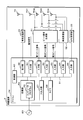
- FIG. 4 is a block diagram showing the main configuration of the on-vehicle apparatus 3.
- the in-vehicle device 3 includes a vehicle transmission unit 30, a beat signal generation unit 31, a vehicle reception unit 32, a GPS reception unit 33, a microcomputer 34, four reception antennas R31, R32, R33, R34, and a transmission antenna T3.
- the microcomputer 34 has six input units 50, 51,..., 55, an output unit 56, an input / output unit 57, a timer 58, a storage unit 59, and a control unit 60.
- the transmission antenna T3 is connected to the vehicle transmission unit 30.
- the vehicle transmission unit 30 is further connected to the output unit 56.
- the four reception antennas R31, R32, R33, and R34 are connected to the beat signal generation unit 31 and the vehicle reception unit 32, respectively.
- the beat signal generation unit 31 is further connected to four input units 50, 51, 52, 53.
- the vehicle reception unit 32 is further connected to the input unit 54.
- the GPS receiver 33 is connected to the input unit 55.
- the six input units 50, 51,..., 55, the output unit 56, the input / output unit 57, the timer 58, the storage unit 59, and the control unit 60 are connected to the bus 61.
- the output unit 56 outputs a digital request signal indicating the content with a plurality of bit values to the vehicle transmission unit 30 according to the instruction of the control unit 60.
- the vehicle transmission unit 30 converts the input digital request signal into an analog request signal having a sinusoidal waveform.
- the vehicle transmission unit 30 wirelessly transmits the converted analog request signal to the wireless terminal 2 via the transmission antenna T3.
- Analog terminal signals are input to each of the four reception antennas R31, R32, R33, and R34.
- the beat signal generation unit 31 receives the four analog terminal signals input to the four reception antennas R31, R32, R33, and R34.
- the vehicle reception unit 32 receives the four analog terminal signals input to the four reception antennas R31, R32, R33, and R34.
- the in-vehicle device 3 functions as a receiving device.
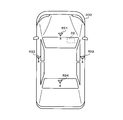
- FIG. 5 is an explanatory view of the arrangement of the receiving antennas R31, R32, R33, and R34. As shown in FIG. 5, receiving antennas R31, R32, R33 and R34 are disposed on the front side, the right side, the left side and the rear side of the vehicle 300, respectively. These positions are stored in the storage unit 59 of the microcomputer 34 at coordinates with the position of the GPS receiving unit 33 as the origin.
- FIG. 6 is an explanatory view of coordinate positions of the receiving antennas R31, R32, R33, and R34.
- the coordinate positions of the receiving antennas R31, R32, R33, and R34 are coordinate positions as viewed from the upper side of the vehicle 300.
- the coordinate positions of the receiving antennas R31, R32, R33 and R34 are stored by two-dimensional coordinates constituted by the x axis and the y axis.
- the axial direction of the x axis coincides with the lateral direction of the vehicle 300, and the axial direction of the y axis coincides with the longitudinal direction of the vehicle 300.
- the origin is the position of the GPS receiver 33.
- the control unit 60 of the microcomputer 34 calculates the coordinate position of the transmission source that has directly transmitted the terminal signal to the on-vehicle apparatus 3 in this two-dimensional coordinate.
- the beat signal generation unit 31 outputs, to the input unit 50 of the microcomputer 34, a notification signal indicating the receiving antenna to which the terminal signal has been input first.
- the input unit 50 notifies the control unit 60 of a reception antenna indicated by the input notification signal.
- the beat signal generation unit 31 treats, as a reference antenna, the reception antenna to which the terminal signal is input first among the four reception antennas R31, R32, R33, and R34.
- the beat signal generation unit 31 mixes the terminal signals input to the reference antenna with the terminal signals input to the remaining three receiving antennas.
- the reference antenna functions as a first antenna, and the remaining three receive antennas each function as a second antenna.
- FIG. 7 is a schematic explanatory view of the operation of the beat signal generator 31.
- the beat signal generation unit 31 includes three mixers 31a, 31b, and 31c.
- the mixer 31a generates an analog first beat signal by mixing the terminal signal input to the reference antenna with the terminal signal input to one of the remaining three receiving antennas.
- the mixer 31b generates an analog second beat signal by mixing the terminal signal input to the reference antenna with the terminal signal input to another one of the remaining three receiving antennas.
- the mixer 31c generates an analog third beat signal by mixing the terminal signal input to the reference antenna with the terminal signal input to the last one of the remaining three receiving antennas.
- the beat signal generation unit 31 converts the analog first beat signal, the second beat signal, and the third beat signal into digital first beat signals, second beat signals, and third beat signals that indicate waveforms.
- the beat signal generation unit 31 outputs the converted digital first beat signal, second beat signal and third beat signal to the input units 51, 52, and 53, respectively.
- the control unit 60 acquires the first beat signal, the second beat signal, and the third beat signal from the input units 51, 52, 53, respectively.
- the two receive antennas involved in generating the first beat signal, the second beat signal and the third beat are predetermined according to the reference antenna, that is, the receive antenna that received the terminal signal first.
- FIG. 8 is a chart showing a receiving antenna related to generation of a beat signal.
- the receiving antennas involved in the generation of the first beat signal are the receiving antennas R31 and R32. That is, the mixer 31a generates the first beat signal by mixing the terminal signal input to the receiving antenna R32 with the terminal signal input to the receiving antenna R31.
- the receiving antennas for generating the second beat signal are the receiving antennas R31 and R33. That is, the mixer 31b generates a second beat signal by mixing the terminal signal input to the reception antenna R33 with the terminal signal input to the reception antenna R31.
- the receiving antennas for generating the third beat signal are the receiving antennas R31 and R34. That is, the mixer 31 c generates a third beat signal by mixing the terminal signal input to the receiving antenna R ⁇ b> 34 with the terminal signal input to the receiving antenna R ⁇ b> 31.
- receiving antennas for generating the first beat signal, the second beat signal, and the third beat signal when the reference antenna is the receiving antenna R32 are also predetermined.
- Receiving antennas for generating the first beat signal, the second beat signal, and the third beat signal when the reference antenna is the receiving antenna R33 are also predetermined.
- Receiving antennas for generating the first beat signal, the second beat signal, and the third beat signal when the reference antenna is the receiving antenna R34 are also predetermined.
- the antenna information indicating the receiving antenna relating to the generation of the first beat signal, the second beat signal, and the third beat signal as illustrated in FIG. 8 is stored in advance in the storage unit 59 of the microcomputer 34.
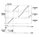
- FIG. 9 is an explanatory diagram of the first beat signal.
- the first beat signal generated by the mixer 31a when the reference antenna is the receiving antenna R31 will be described. Therefore, the mixer 31a mixes the terminal signal input to the receiving antenna R32 with the terminal signal input to the receiving antenna R31.
- FIG. 9 shows the transition of the frequency of the terminal signal input to each of the reception antennas R31 and R32 and the transition of the frequency of the first beat signal.
- the horizontal axis represents time.
- the transition of the frequency of the terminal signal input to each of the receiving antennas R31 and R32 is indicated by thick lines and thin lines.
- the frequency of the terminal signal transmitted by the terminal transmission unit 21 of the wireless terminal 2 via the transmission antenna T2 rises at a constant slope from the reference frequency each time the reference time elapses. Therefore, the frequency of the terminal signal input to each of the receiving antennas R31 and R32 similarly rises at a constant inclination from the reference frequency each time the reference time elapses.
- FIG. 9 shows an example in which the number of set frequencies is three, as in FIG.
- the frequency of the terminal signal input to the receiving antenna R32 changes in the same manner as the frequency of the terminal signal input to the receiving antenna R31. Further, since the reference antenna is the receiving antenna R31, after the terminal signal is input to the receiving antenna R31, the terminal signal is input to the receiving antenna R32. Therefore, the frequency of the terminal signal input to the receiving antenna R32 shifts so as to follow the frequency of the terminal signal input to the receiving antenna R31.
- the frequency of the first beat signal is the difference (absolute value) of the frequency of the terminal signal input to each of the receiving antennas R31 and R32.
- an initial period a period from the terminal signal being input to the receiving antenna R31 to the elapse of the reference time described above.
- the frequency of the first beat signal rises at a constant slope with the passage of time, similarly to the frequency of the terminal signal input to the receiving antenna R31, until the terminal signal is input to the receiving antenna R32.
- the frequency of the terminal signal input to the receiving antennas R31 and R2 rises with the same slope, so the frequency of the first beat signal is constant.
- a detection period of the first beat signal is provided immediately before the end of the initial period, and the control unit 60 detects the frequency of the first beat signal within the detection period.
- the frequency to be detected is the frequency of the first beat signal which changes constantly in the initial period.
- the frequency of the first beat signal detected within the detection period is higher as the delay time from the terminal signal being input to the receiving antenna R31 to the terminal signal being input to the receiving antenna R32 is longer.
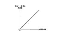
- FIG. 10 is a graph showing the relationship between the frequency of the first beat signal and the delay time.
- the frequency of the first beat signal is a frequency detected within the detection period.
- the frequency of the first beat signal rises with a constant slope as the delay time rises. Therefore, the frequency of the first beat signal detected in the detection period indicates the delay time from the terminal signal being input to the receiving antenna R31 to the terminal signal being input to the receiving antenna R32.
- a graph showing the relationship between the frequency of the first beat signal and the delay time is stored in advance in the storage unit 59.
- the frequency of the first beat signal shifts in accordance with the difference (absolute value) of the frequency of the terminal signal input to the receiving antennas R31 and R32.
- the frequencies of the second beat signal and the third beat signal generated by the mixers 31b and 31c when the reference antenna is the receiving antenna R31 also change in the same manner as the frequency of the first beat signal.
- the second beat signal is a signal generated by mixing the terminal signals input to the receiving antennas R31 and R33
- the third beat signal is input to the receiving antennas R31 and R34. These signals are generated by mixing different terminal signals. Therefore, the frequency of the second beat signal is the difference (absolute value) of the frequency of the terminal signal input to each of the receiving antennas R31 and R33.
- the frequency of the third beat signal is the difference (absolute value) of the frequency of the terminal signal input to each of the receiving antennas R31 and R34.
- a frequency detection period is provided immediately before the end of the initial period, and the frequency detected in the detection period has a longer delay time ,high.
- a graph indicating the relationship between the frequency and the delay time as shown in FIG. 10 is stored in advance in the storage unit 59.
- the frequency of the second beat signal detected within the detection period indicates the delay time from the terminal signal being input to the receiving antenna R31 to the terminal signal being input to the receiving antenna R33.
- the frequency of the third beat signal detected within the detection period indicates the delay time from the terminal signal being input to the receiving antenna R31 to the terminal signal being input to the receiving antenna R33.
- the control unit 60 performs the first beat signal, the second beat signal, and the third beat signal as in the case where the reference antenna is the receiving antenna R31.
- a graph showing the relationship between the frequency and the delay time as shown in FIG. 10 is stored in advance in the storage unit 59.
- the vehicle reception unit 32 illustrated in FIG. 4 selects a terminal signal with the best sensitivity, for example, a terminal signal with the largest amplitude, among the received four terminal signals. .
- the vehicle receiver 32 converts the selected analog terminal signal into a digital terminal signal whose content is indicated by a plurality of bit values, and outputs the converted digital terminal signal to the input unit 54 of the microcomputer 34.
- the vehicle reception unit 32 may combine four analog terminal signals without performing selection.
- the vehicle receiving unit 32 converts the synthesized analog terminal signal into a digital terminal signal, and outputs the converted digital terminal signal to the input unit 54 of the microcomputer 34.
- the control unit 60 acquires terminal position information included in the terminal signal from the input unit 54.
- the GPS reception unit 33 Similar to the GPS reception unit 22 of the wireless terminal 2, the GPS reception unit 33 also periodically receives a plurality of radio waves from a plurality of GPS satellites.
- the GPS receiving unit 33 measures the position of the GPS receiving unit 33, that is, the in-vehicle device 3 based on the received plurality of radio waves each time it receives a plurality of radio waves from a plurality of GPS satellites, and indicates the measured position
- the position information is output to the input unit 55 of the microcomputer 34.
- the control unit 60 acquires device position information indicating the position of the GPS receiving unit 33 from the input unit 55.
- an instruction signal for instructing confirmation of the position of the wireless terminal 2 is not shown. It is input to the input / output unit 57 from an external device.
- the input / output unit 57 outputs the absence signal, the normal signal and the abnormality signal to the external device according to the instruction of the control unit 60.
- the absence signal indicates that the wireless terminal 2 is absent near the vehicle 300.
- the normal signal indicates that the wireless terminal 2 is present in or near the vehicle 300 and the source of the terminal signal transmitted directly to the on-vehicle apparatus 3 is the wireless terminal 2.
- the abnormal signal indicates that the transmission source that has transmitted the terminal signal directly to the in-vehicle apparatus 3 is not the wireless terminal 2.
- the timer 58 starts and ends timing according to an instruction of the control unit 60.
- the time measured by the timer 58 is read from the timer 58 by the control unit 60.
- the storage unit 59 is a non-volatile memory. As described above, in the storage unit 59, the coordinate positions of the receiving antennas R31, R32, R33, R34 with the position of the GPS receiving unit 33 as the origin, the antenna information, the first beat signal, the second beat signal, the second And a graph showing the relationship between frequency and delay time for each of the 3-beat signals.
- the antenna information is information indicating the receiving antenna related to the generation of each of the first beat signal, the second beat signal, and the third beat signal as shown in FIG.
- the storage unit 59 further stores a computer program P3.
- the control unit 60 has a CPU (not shown).
- the CPU of the control unit 60 executes the confirmation process by executing the computer program P3.
- the confirmation process is a process of confirming the position of the wireless terminal 2.
- the computer program P3 is used to cause the CPU of the control unit 60 to execute confirmation processing.
- the computer program P3 may be stored in the storage medium E3 so as to be readable by the CPU of the control unit 60.
- the computer program P3 read from the storage medium E3 by a reading device (not shown) is stored in the storage unit 59.
- the storage medium E3 is an optical disk, a flexible disk, a magnetic disk, a magnetic optical disk, a semiconductor memory, or the like.
- the optical disc is a CD (Compact Disc) -ROM (Read Only Memory), a DVD (Digital Versatile Disc) -ROM, a BD (Blu-ray (registered trademark) Disc), or the like.
- the magnetic disk is, for example, a hard disk.
- the computer program P3 may be downloaded from an external device (not shown) connected to a communication network (not shown), and the downloaded computer program P3 may be stored in the storage unit 59.
- FIG. 11 is a flowchart showing the procedure of confirmation processing.
- the control unit 60 executes a confirmation process when an instruction signal is input to the input / output unit 57. First, the control unit 60 instructs the output unit 56 to cause the vehicle transmission unit 30 to output a digital request signal (step S1).
- the vehicle transmitting unit 30 converts the digital request signal input from the output unit 56 into an analog request signal, and converts the converted analog request signal to the wireless terminal 2 via the transmitting antenna T3.
- the control unit 44 executes transmission processing, and the terminal transmitting unit 21 transmits an analog terminal signal via the transmitting antenna T2.
- the beat signal generation unit 31 inputs a notification signal indicating the reference antenna, that is, the receiving antenna to which the terminal signal is initially input to the microcomputer 34. Output to 50.
- step S1 the control unit 60 of the in-vehicle device 3 instructs the timer 58 to start clocking (step S2), and determines whether a notification signal is input to the input unit 50 (step S3) .
- the control unit 60 determines whether the timed time kept by the timer 58 is equal to or longer than the reference time (step S4).
- the control unit 60 executes step S3, and a notification signal is input to the input unit 50, or the clocked time is equal to or longer than the reference time. Wait until it is
- control unit 60 determines that the clocked time is equal to or longer than the reference time (S4: YES), it instructs the timer 58 to end the clocking (step S5), and instructs the input / output unit 57 to An absence signal indicating that the vehicle 2 is absent near the vehicle 300 is output to the external device (step S6). In this case, for example, the vehicle operation such as locking or unlocking of the door or starting of the engine is not performed according to the instruction received by pressing the push button. After executing step S6, the control unit 60 ends the confirmation process.
- the control unit 60 determines that the notification signal is input (S3: YES)
- the control unit 60 instructs the timer 58 to end the clocking (step S7), and the first input to the input units 51, 52, 53 is performed.
- the frequencies of the beat signal, the second beat signal, and the third beat signal are detected (step S8). These frequencies are frequencies within the detection period described above.
- generation of a 1st beat signal, a 2nd beat signal, and a 3rd beat signal is predetermined by the reference
- control unit 60 determines three delay times based on the three frequencies detected in step S8 (step S9).
- three graphs showing the relationship between the frequency of each of the first beat signal, the second beat signal and the third beat signal and the delay time are used.
- the control unit 60 functions as a determination unit.
- control unit 60 calculates the coordinate position of the transmission source that has directly transmitted the terminal signal to the on-vehicle apparatus 3 based on the three delay times determined in step S9 (step S10). The calculation of the coordinate position of the transmission source will be described in detail later.
- the terminal signal corresponds to a common signal.
- the control unit 60 also functions as a position calculation unit.
- the control unit 60 After executing step S10, the control unit 60 acquires, from the input unit 55, the device position information 11 indicating the position of the GPS reception unit 33 measured by the GPS reception unit 33 (step S11). Next, the control unit 60 acquires terminal position information included in the terminal signal input from the vehicle reception unit 32 to the input unit 54 (step S12). The control unit 60 also functions as an acquisition unit. Next, the control unit 60 calculates the coordinate position of the wireless terminal 2 based on the device position information acquired in steps S11 and S12 and the position of the GPS receiving unit 33 and the wireless terminal 2 indicated by the terminal position information (step S13). ).
- control unit 60 determines whether the distance between the two coordinate positions calculated in steps S10 and S13 is less than the reference distance (step S14).
- the reference distance is stored in advance in the storage unit 59 and is constant.
- the control unit 60 also functions as a determination unit.
- control unit 60 determines that the distance between the two coordinate positions is less than the reference distance (S14: YES)
- the control unit 60 instructs the input / output unit 57 to locate the wireless terminal 2 in or near the vehicle 300.
- a normal signal indicating that the transmission source is the wireless terminal 2 is transmitted to the external device (step S15).
- the vehicle operation is performed according to the instruction received by pressing the push button.
- control unit 60 determines that the distance between the two coordinate positions is equal to or greater than the reference distance (S14: NO)
- the control unit 60 instructs the input / output unit 57 to transmit the terminal signal instead of the wireless terminal 2 as the transmission source.
- An abnormality signal indicating that the relay device is to be relayed is output to the external device (step S16). In this case, for example, the vehicle operation is not performed in accordance with the instruction received by pressing the push button, and the relay device notifies that relay is being performed.
- the control unit 60 ends the confirmation process. Note that determining that the distance between two coordinate positions is equal to or greater than the reference distance corresponds to detecting a relay performed by the relay.
- the reference antenna is the receiving antenna R31.
- the delay time determined based on the frequency of the first beat signal is from the terminal signal being input to the receiving antenna R31 to the terminal signal being input to the receiving antenna R32. It's time.
- the delay time determined based on the frequency of the second beat signal is the time from the terminal signal being input to the receiving antenna R31 to the terminal signal being input to the receiving antenna R33.
- the delay time determined based on the frequency of the third beat signal is the time from the terminal signal being input to the receiving antenna R31 to the terminal signal being input to the receiving antenna R34.
- the delay time from the terminal signal being input to the receiving antenna R31 to the terminal signal being input to each of the receiving antennas R32, R33, R34 is described as ⁇ 2, ⁇ 3 and ⁇ 4.
- the coordinate positions of the transmission source and the receiving antennas R31, R32, R33, R34 are respectively (X0, Y0), (X1, Y1), (X2) , Y2), (X3, Y3) and (X4, Y4).
- the distances from the transmission source to the reception antennas R31, R32, R33, and R34 are described as D1, D2, D3, and D4, respectively.
- the speed of light in vacuum is described as C.
- D2-D1 C ⁇ ⁇ 2 ... [1]
- D3-D1 C ⁇ ⁇ 3 ... [2]
- D4-D1 C ⁇ ⁇ 4 ... [3]
- ⁇ represents a product.
- the distances D2, D3 and D4 are expressed as follows using coordinate positions (X0, Y0), (X2, Y2), (X3, Y3), and (X4, Y4).
- D2 ⁇ ((X2-X0) 2 + (Y2-Y0) 2 ) ... [6]
- D3 (((X3-X0) 2 + (Y3-Y0) 2 ) ... [7]
- D4 (((X4-X0) 2 + (Y4-Y0) 2 ) ... [8]
- the positions of the receiving antennas R31, R32, R33, R34 and the GPS receiving unit 33 are fixed in the vehicle 300. For this reason, coordinate positions (X1, Y1), (X2, Y2), (X3, Y3), and (X4, Y4) are known.
- the velocity C of light propagating in vacuum is also known.
- step S10 of the confirmation process the control unit 60 solves the simultaneous equations configured by the equations [9] and [10] using the three delay times ⁇ 2, ⁇ 3, and ⁇ 4 determined in step S9.
- the coordinate position (X0, Y0) of the transmission source is calculated.
- the control unit 60 calculates the two time differences ( ⁇ 3- ⁇ 2) and ( ⁇ 4- ⁇ 2) by subtracting the delay time ⁇ 2 from the two delay times ⁇ 3 and ⁇ 4, respectively, and calculates the two time differences.
- the coordinate position of the transmission source is calculated based on ( ⁇ 3- ⁇ 2) and ( ⁇ 4- ⁇ 2).
- the control unit 60 functions as a time difference calculation unit. In this calculation, the delay time ⁇ 2 corresponds to the first delay time, and each of the delay times ⁇ 3 and ⁇ 4 corresponds to the second delay time.
- the coordinate position (X0, Y0) of the transmission source may be calculated using the coordinates shown in FIG. First, a curve of coordinate position (X, Y) satisfying the following equation (11) is drawn.
- This coordinate position is a position at which the value calculated by subtracting the distance from the reception antenna R32 from the distance from the reception antenna R33 is C ⁇ ( ⁇ 3 ⁇ 2).
- ⁇ ((X3-X) 2 + (Y3-Y) 2) - ⁇ ((X2-X) 2 + (Y2-Y) 2) C ⁇ ( ⁇ 3- ⁇ 2) ⁇ [11]
- This coordinate position is a position at which the value calculated by subtracting the distance from the reception antenna R32 from the distance from the reception antenna R34 is C ⁇ ( ⁇ 4 ⁇ 2).
- ⁇ ((X 4 ⁇ X) 2 + (Y 4 ⁇ Y) 2 ) ⁇ (((X 2 ⁇ X) 2 + (Y 2 ⁇ Y) 2 ) C ⁇ ( ⁇ 4 ⁇ ⁇ 2) ...
- the coordinate position of the intersection of the two curves described above is the coordinate position (X0, Y0) of the transmission source.
- the coordinate position of the transmission source is calculated in the same manner as in the case where the reference antenna is the reception antenna R31.
- the control unit 60 determines that the distance between the coordinate positions of the transmission source and the wireless terminal 2 is equal to or greater than the reference distance, and detects relaying performed by the relay device.
- the control unit 60 determines the distance between these coordinate positions as the reference distance Determined to be less than.
- the terminal signal transmitted by the wireless terminal 2 is not limited to a signal whose frequency rises with the passage of time as in the first embodiment.
- the differences between the second embodiment and the first embodiment will be described below.
- the configuration other than the configuration to be described later is the same as that of the first embodiment. Therefore, the same components as those of the first embodiment are denoted by the same reference numerals as those of the first embodiment and the description thereof is omitted.
- FIG. 12 is an explanatory diagram of the frequency and waveform of a terminal signal in the second embodiment.
- FIG. 12 corresponds to FIG. Similar to FIG. 3,
- FIG. 12 shows an example of the transition of the frequency of the terminal signal and an example of the waveform of the terminal signal.
- the horizontal axis represents time.
- the frequency of the terminal signal transmitted by the terminal transmission unit 21 of the wireless terminal 2 decreases at a constant slope with the passage of time.
- the wave period spreads with the passage of time.
- the terminal transmission unit 21 transmits a terminal signal using three frequency bands B1, B2, and B3.
- the terminal transmission unit 21 decreases the frequency of the terminal signal with time from the reference frequency which is one of three preset setting frequencies f1, f2 and f3 each time the reference time passes.
- the terminal transmission unit 21 causes the terminal position information to be included in the terminal signal as in the first embodiment by changing the reference frequency to one of the three set frequencies f1, f2 and f3 with the passage of time.
- the terminal transmission unit 21 changes the reference frequency in the order of the set frequencies f1, f3, f2, f3, and f2. Changing the reference frequency to each of the set frequencies f1, f2 and f3 corresponds to changing the frequency band that raises the frequency with the passage of time to the frequency bands B1, B2 and B3.
- the number of setting frequencies set as the reference frequency that is, the number of frequency bands used for the transmission of the terminal signal is not limited to three, and may be two or four or more. It may be.
- the number of setting frequencies is preferably 2 k -1 (k: an integer of 2 or more).
- FIG. 13 is an explanatory diagram of the first beat signal.
- FIG. 13 corresponds to FIG.
- the reference antenna is the receiving antenna R31
- a first beat signal generated by the mixer 31a of the beat signal generation unit 31 will be described. Therefore, the mixer 31a mixes the terminal signal input to the receiving antenna R32 with the terminal signal input to the receiving antenna R31.
- FIG. 13 shows the transition of the frequency of the terminal signal input to each of the reception antennas R31 and R32 and the transition of the frequency of the first beat signal.
- the horizontal axis represents time.
- the transition of the frequency of the terminal signal input to each of the receiving antennas R31 and R32 is indicated by thick lines and thin lines.
- the frequency of the terminal signal transmitted by the terminal transmission unit 21 of the wireless terminal 2 via the transmission antenna T2 decreases at a constant inclination from the reference frequency each time the reference time elapses. For this reason, the frequency of the terminal signal input to each of the receiving antennas R31 and R32 similarly decreases with a constant inclination from the reference frequency each time the reference time elapses.
- FIG. 13 shows an example in which the number of set frequencies is three, as in FIG.
- the frequency of the terminal signal input to the receiving antenna R32 shifts so as to follow the frequency of the terminal signal input to the receiving antenna R31 as in the first embodiment.
- the frequency of the first beat signal is received until the terminal signal is input to the receiving antenna R32 within the initial period which is the period from when the terminal signal is input to the receiving antenna R31 until the above-mentioned reference time elapses. Similar to the frequency of the terminal signal input to the antenna R31, the frequency decreases at a constant slope with the passage of time. In the initial period, after the terminal signal is input to the receiving antenna R32, the frequency of the terminal signal input to the receiving antennas R31 and R2 decreases at the same inclination, so the frequency of the first beat signal is constant. .
- the control unit 60 detects the frequency of the first beat signal within the detection period provided immediately before the end of the initial period.
- the frequency to be detected is the frequency of the first beat signal which changes constantly in the initial period.
- the frequency of the first beat signal detected within the detection period is higher as the delay time from the terminal signal being input to the receiving antenna R31 to the terminal signal being input to the receiving antenna R32 is longer.
- the relationship between the frequency and delay time of the first beat signal is the same as that of the first embodiment (see FIG. 10).
- the frequency of the first beat signal shifts in accordance with the difference (absolute value) of the frequency of the terminal signal input to the receiving antennas R31 and R32.
- the frequencies of the second beat signal and the third beat signal generated by the mixers 31b and 31c when the reference antenna is the receiving antenna R31 also change in the same manner as the frequency of the first beat signal.
- a frequency detection period is provided immediately before the end of the initial period, and the frequency detected in the detection period has a longer delay time ,high.
- the control unit 60 performs the first beat signal, the second beat signal, and the third beat signal as in the case where the reference antenna is the receiving antenna R31.
- the arrangement of the four reception antennas R31, R32, R33, and R34 is not limited to the front side, the right side, the left side, and the rear side of the vehicle 300. These may be disposed at mutually different positions in the vehicle 300. Further, the direction of the x-axis is not limited to the lateral direction of the vehicle 300, and the direction of the y-axis is not limited to the longitudinal direction of the vehicle 300. It is sufficient that the coordinate position viewed from the upper side of the vehicle 300 can be indicated by the coordinate constituted by the x axis and the y axis.
- the control unit 60 calculates the coordinate position (X0, Y0) of the transmission source using the equations [1] and [2]. May be
- the distance D1 can be expressed by the following equation [13] using coordinate positions (X0, Y0) and (X1, Y1) of the transmission source and the reception antenna R31, respectively.
- D1 ⁇ ((X1 ⁇ X0) 2 + (Y1 ⁇ Y0) 2 ) ⁇ [13]
- the coordinate positions (X1, Y1), (X2, Y2), (X3, Y3) and the velocity C of light are known. Therefore, the coordinate position (X0, Y0) of the transmission source is calculated by solving the simultaneous equations of [14] and [15].
- the coordinate position (X0, Y0) of the transmission source may be calculated using the coordinates shown in FIG.
- a curve at coordinate position (X, Y) satisfying the following equation (16) is drawn.
- ⁇ ((X2-X) 2 + (Y 2 -Y) 2 ) - ⁇ ((X 1 -X) 2 + (Y 1 -Y) 2 ) C ⁇ ⁇ 2 ...
- a curve at coordinate position (X, Y) satisfying the following equation (17) is drawn.
- ⁇ ((X3-X) 2 + (Y 3 -Y) 2 )-((X 1 -X) 2 + (Y 1 -Y) 2 ) C ⁇ ⁇ 3 ... [17]
- the coordinate position of the intersection of the two curves described above is the coordinate position (X0, Y0) of the transmission source.
- the coordinate position of the transmission source is calculated in the same manner as in the case where the reference antenna is the reception antenna R31.
- the coordinate position (X0, Y0) of the transmission source is calculated using the equation [1] and the equation [2], the delay time ⁇ 4 relating to the receiving antenna R34 and the third beat signal is unnecessary. Therefore, the number of receiving antennas in the on-vehicle apparatus 3 may be three. Further, the number of receiving antennas included in the in-vehicle device 3 is not limited to three or four, and may be five or more.
- the wireless terminal 2 may be an electronic key as long as it is a terminal that transmits a signal wirelessly.
- transmission of the request signal from the on-vehicle apparatus 3 to the wireless terminal 2 is performed using a frequency of 30 to 300 kHz, and transmission of a terminal signal from the wireless terminal 2 to the on-vehicle apparatus 3 is 30 to 300 MHz. It is done using frequency.
Landscapes
- Engineering & Computer Science (AREA)
- Mechanical Engineering (AREA)
- Physics & Mathematics (AREA)
- General Physics & Mathematics (AREA)
- Radar, Positioning & Navigation (AREA)
- Remote Sensing (AREA)
- Traffic Control Systems (AREA)
- Position Fixing By Use Of Radio Waves (AREA)
Abstract
車載装置(3)では、車両受信部(32)は、複数の受信アンテナ(R31,R32,R33,R34)を介して信号を受信する。制御部(60)は、複数の受信アンテナ(R31,R32,R33,R34)夫々に入力された共通信号の周波数に基づいて、共通信号の送信元の位置を算出する。制御部(60)は、算出した位置と、共通信号に含まれる位置情報が示す位置との間の距離が所定距離未満であるか否かを判定する。
Description
本発明は、受信装置、通信システム、距離判定方法及びコンピュータプログラムに関する。
本出願は、2017年9月22日出願の日本出願第2017-182908号に基づく優先権を主張し、前記日本出願に記載された全ての記載内容を援用するものである。
本出願は、2017年9月22日出願の日本出願第2017-182908号に基づく優先権を主張し、前記日本出願に記載された全ての記載内容を援用するものである。
特許文献1には、悪意ある第三者がドアをアンロックすることを防止する通信システムが開示されている。この通信システムでは、無線端末は、応答信号の送信を要求する要求信号を車載装置から受信した場合、自身の位置を示す位置情報を含む応答信号を車載装置に送信する。
車載装置が応答信号を受信した場合において、応答信号に含まれる位置情報が示す無線端末の位置が所定範囲内の位置であるとき、ドアがアンロックされる。無線端末の位置が所定範囲外の位置であるとき、ドアがアンロックされることはない。このため、無線端末の位置が所定範囲外の位置である限り、たとえ、中継機が行う中継によって、車載装置が応答信号を受信した場合であっても、ドアがアンロックされることはない。
本発明の一態様に係る受信装置は、複数の受信アンテナを介して信号を受信する車両用の受信装置であって、前記複数の受信アンテナ夫々に入力された共通信号の周波数に基づいて、該共通信号の送信元の位置を算出する位置算出部と、該共通信号に含まれる位置情報を取得する取得部と、前記位置算出部が算出した位置、及び、前記取得部が取得した位置情報が示す位置の間の距離が所定距離未満であるか否かを判定する判定部とを備える。
本発明の一態様に係る通信システムは、前述した受信装置と、所定時間が経過する都度、周波数が基準周波数から時間の経過とともに上昇又は低下する前記共通信号を無線で送信する無線端末とを備え、該共通信号には、前記無線端末の位置を示す位置情報が含まれる。
本発明の一態様に係る距離判定方法は、複数の受信アンテナ夫々に入力された共通信号の周波数に基づいて、該共通信号の送信元の位置を算出するステップと、該共通信号に含まれる位置情報を取得するステップと、算出した位置と、取得した位置情報が示す位置との間の距離が所定距離未満であるか否かを判定するステップとを含む。
本発明の一態様に係るコンピュータプログラムは、コンピュータに、複数の受信アンテナ夫々に入力された共通信号の周波数に基づいて、該共通信号の送信元の位置を算出するステップと、該共通信号に含まれる位置情報を取得するステップと、算出した位置と、取得した位置情報が示す位置との間の距離が所定距離未満であるか否かを判定するステップとを実行させる。
なお、本発明を、このような特徴的な処理部を備える受信装置として実現することができるだけでなく、かかる特徴的な処理をステップとする受信方法として実現したり、かかるステップをコンピュータに実行させるためのコンピュータプログラムとして実現したりすることができる。また、本発明を、受信装置の一部又は全部を実現する半導体集積回路として実現したり、受信装置を含む受信システムとして実現したりすることができる。
[本開示が解決しようとする課題]
特許文献1に記載の通信システムでは、車載装置は、中継機が行っている中継を検知することができない。従って、無線端末が所定範囲内にある状況では、悪意ある第三者は、無線端末及び車載装置間に中継機を配置し、ドアノブの押ボタンを押すことによって、ドアをアンロックすることができる。このため、悪意ある第三者によるドアのアンロックを防止する対策が不十分である。
特許文献1に記載の通信システムでは、車載装置は、中継機が行っている中継を検知することができない。従って、無線端末が所定範囲内にある状況では、悪意ある第三者は、無線端末及び車載装置間に中継機を配置し、ドアノブの押ボタンを押すことによって、ドアをアンロックすることができる。このため、悪意ある第三者によるドアのアンロックを防止する対策が不十分である。
そこで、中継機が行っている中継を検知することができる受信装置、通信システム、距離判定方法及びコンピュータプログラムを提供することを目的とする。
[本開示の効果]
本開示によれば、中継機が行っている中継を検知することができる。
本開示によれば、中継機が行っている中継を検知することができる。
[本発明の実施形態の説明]
最初に本発明の実施態様を列挙して説明する。以下に記載する実施形態の少なくとも一部を任意に組み合わせてもよい。
最初に本発明の実施態様を列挙して説明する。以下に記載する実施形態の少なくとも一部を任意に組み合わせてもよい。
(1)本発明の一態様に係る受信装置は、複数の受信アンテナを介して信号を受信する車両用の受信装置であって、前記複数の受信アンテナ夫々に入力された共通信号の周波数に基づいて、該共通信号の送信元の位置を算出する位置算出部と、該共通信号に含まれる位置情報を取得する取得部と、前記位置算出部が算出した位置、及び、前記取得部が取得した位置情報が示す位置の間の距離が所定距離未満であるか否かを判定する判定部とを備える。
(2)本発明の一態様に係る受信装置は、前記複数の受信アンテナに含まれる第1アンテナに入力された前記共通信号を、前記複数の受信アンテナに含まれる複数の第2アンテナに入力された複数の前記共通信号夫々に混合することによって、複数のビート信号を生成する生成部と、該生成部が生成した複数のビート信号の周波数に基づいて、前記共通信号が前記第1アンテナに入力されてから、該共通信号が前記複数の第2アンテナ夫々に入力されるまでの複数の遅延時間を決定する決定部とを備え、前記位置算出部は、前記決定部が決定した複数の遅延時間に基づいて、前記送信元の位置を算出する。
(3)本発明の一態様に係る受信装置は、前記決定部が決定した複数の遅延時間に含まれる第1遅延時間を、該複数の遅延時間に含まれる複数の第2遅延時間夫々から減算することによって、複数の時間差を算出する時間差算出部を備え、前記位置算出部は、該時間差算出部が算出した複数の時間差に基づいて、前記送信元の位置を算出する。
(4)本発明の一態様に係る通信システムは、前述した受信装置と、所定時間が経過する都度、周波数が基準周波数から時間の経過とともに上昇又は低下する前記共通信号を無線で送信する無線端末とを備え、該共通信号には、前記無線端末の位置を示す位置情報が含まれる。
(5)本発明の一態様に係る通信システムは、前記無線端末は、前記基準周波数を時間の経過とともに変更することによって、前記共通信号に前記位置情報を含ませる。
(6)本発明の一態様に係る距離判定方法は、複数の受信アンテナ夫々に入力された共通信号の周波数に基づいて、該共通信号の送信元の位置を算出するステップと、該共通信号に含まれる位置情報を取得するステップと、算出した位置と、取得した位置情報が示す位置との間の距離が所定距離未満であるか否かを判定するステップとを含む。
(7)本発明の一態様に係るコンピュータプログラムは、コンピュータに、複数の受信アンテナ夫々に入力された共通信号の周波数に基づいて、該共通信号の送信元の位置を算出するステップと、該共通信号に含まれる位置情報を取得するステップと、算出した位置と、取得した位置情報が示す位置との間の距離が所定距離未満であるか否かを判定するステップとを実行させる。
上記の一態様に係る受信装置、距離判定方法及びコンピュータプログラムにあっては、無線端末が送信した共通信号が中継機によって中継され、複数の受信アンテナに入力され、共通信号に無線端末の位置を示す位置情報が含まれていると仮定する。この場合、複数の受信アンテナ夫々に入力された共通信号の周波数に基づいて、共通信号の送信元である中継機の位置が算出される。位置情報は無線端末の位置を示すので、算出された位置は位置情報が示す位置と異なる。結果、算出した位置と位置情報が示す位置との間の距離が所定距離以上であると判定し、中継機が行っている中継を検知する。
中継機が共通信号を中継していない場合、算出した位置は、位置情報が示す位置と略一致するので、算出した位置と位置情報が示す位置との間の距離が所定距離未満であると判定する。
上記の一態様に係る受信装置にあっては、共通信号は、周波数が時間の経過とともに上昇又は低下する信号であると仮定する。ビート信号の周波数は、第1アンテナ及び第2アンテナに入力された2つの共通信号の周波数の差分(絶対値)である。共通信号が第1アンテナに入力されてから、共通信号が第2アンテナに入力されるまでの遅延時間が長い程、ビート信号の周波数が高い。共通信号の伝播速度は、真空中を伝播する光の速度とみなすことができるので、遅延時間は、送信元から第1アンテナまでの距離と、送信元から第2アンテナまでの距離との差分を示す。複数の第2アンテナに対応する複数の遅延時間に基づいて、送信元の位置を算出する。
上記の一態様に係る受信装置にあっては、第2遅延時間から第1遅延時間を減算することによって算出される時間差は、第1遅延時間に係る第2アンテナに共通信号が入力されてから、第2遅延時間に係る第2アンテナに共通信号が入力されるまでの時間を示す。即ち、この時間差は、送信元から第1遅延時間に係る第2アンテナまでの距離と、送信元から第2遅延時間に係る第2アンテナまでの距離との差分を示す。複数の第2遅延時間夫々から第1遅延時間を減算し、その結果に基づいて、送信元の位置を算出する。
上記の一態様に係る通信システムにあっては、共通信号は、所定時間が経過する都度、周波数が基準周波数から時間の経過とともに上昇又は低下する信号である。共通信号に含まれる位置情報は、無線端末の位置を示す。
上記の一態様に係る通信システムにあっては、ビット値「0」を共通信号に含ませる場合、例えば、基準周波数を第1周波数、第2周波数及び第3周波数の順に変更する。また、ビット値「1」を共通信号に含ませる場合、例えば、基準周波数を第2周波数、第3周波数及び第1周波数の順に変更する。これにより、位置情報を共通信号に含ませることができる。
[本発明の実施形態の詳細]
本発明の実施形態に係る通信システムの具体例を、以下に図面を参照しつつ説明する。なお、本発明はこれらの例示に限定されるものではなく、請求の範囲によって示され、請求の範囲と均等の意味および範囲内でのすべての変更が含まれることが意図される。
本発明の実施形態に係る通信システムの具体例を、以下に図面を参照しつつ説明する。なお、本発明はこれらの例示に限定されるものではなく、請求の範囲によって示され、請求の範囲と均等の意味および範囲内でのすべての変更が含まれることが意図される。
(実施形態1)
図1は、実施形態1における通信システム1の要部構成を示すブロック図である。通信システム1は、無線端末2及び車載装置3を備える。車載装置3は車両300に搭載されている。無線端末2及び車載装置3は、無線で相互に通信する。
図1は、実施形態1における通信システム1の要部構成を示すブロック図である。通信システム1は、無線端末2及び車載装置3を備える。車載装置3は車両300に搭載されている。無線端末2及び車載装置3は、無線で相互に通信する。
車載装置3は、所定の条件が満たされた場合、無線端末2の位置を示す端末位置情報を含む端末信号の送信を要求する要求信号を無線端末2に無線で送信する。所定の条件は、車両300の図示しないドアのドアノブに設けられている押ボタンの押下、又は、車両300のエンジンの始動を受ける押ボタンの押下等である。
無線端末2は、要求信号を受信した場合、自身(無線端末2)の位置を示す端末位置情報を取得し、取得した端末位置情報を含む端末信号を車載装置3に無線で送信する。
車載装置3は、端末信号を受信した場合、車載装置3に端末信号を直接に送信した送信元の位置を算出し、算出した送信元の位置と、端末信号に含まれる端末位置情報が示す無線端末2の位置との間の距離が所定距離未満であるか否かを判定する。
車載装置3によって、距離が所定距離未満であると判定された場合、端末信号の送信元は無線端末2であるとして、車両300では、ドアのロック若しくはアンロック、又は、エンジンの始動等の車両動作が行われる。
車載装置3は、距離が所定距離以上であると判定した場合、端末信号の送信元は無線端末2ではなく、中継機が端末信号を中継していることを検知する。この場合、ドアのロック若しくはアンロック、又は、エンジンの始動等の車両動作が行われることはない。
無線端末2は、例えば、スマートフォンである。この場合、例えば、車載装置3から無線端末2への要求信号の送信は、NFC(Near Field Communication)の通信規格に従って行われ、無線端末2から車載装置3への端末信号の送信は、Bluetooth(登録商標)の通信規格に従って行われる。要求信号の送信は、例えば、13.56MHz帯の周波数を用いて行われる。端末信号の送信は、例えば、2.4GHz帯の周波数を用いて行われる。
図2は、無線端末2の要部構成を示すブロック図である。無線端末2は、端末受信部20、端末送信部21、GPS(Global Positioning System)受信部22、マイクロコンピュータ(以下、マイコンという)23、受信アンテナR2及び送信アンテナT2を有する。マイコン23は、入力部40,41、出力部42、記憶部43及び制御部44を有する。
受信アンテナR2は端末受信部20に接続されている。端末受信部20は、更に、マイコン23の入力部40に接続されている。送信アンテナT2は端末送信部21に接続されている。端末送信部21は、更に、マイコン23の出力部42に接続されている。GPS受信部22は、マイコン23の入力部41に接続されている。入力部40,41、出力部42、記憶部43及び制御部44はバス45に接続されている。
受信アンテナR2には、正弦波状の波形を有するアナログの要求信号が入力される。端末受信部20は、受信アンテナR2に入力されたアナログの要求信号を受信する。端末受信部20は、アナログの要求信号を受信した場合、受信したアナログの要求信号を、複数のビット値で内容を示すデジタルの要求信号に変換し、変換したデジタルの要求信号をマイコン23の入力部40に出力する。入力部40は、端末受信部20から要求信号が入力された場合、入力された要求信号の内容を制御部44に通知する。
出力部42は、制御部44の指示に従って、複数のビット値で内容を示すデジタルの端末信号を端末送信部21に出力する。端末送信部21は、出力部42からデジタルの端末信号が入力された場合、入力されたデジタルの端末信号を、正弦波状の波形を有するアナログの端末信号に変換し、変換したアナログの端末信号を、送信アンテナT2を介して車載装置3に無線で送信する。
GPS受信部22は、複数のGPS衛星から複数の電波を周期的に受信する。GPS受信部22は、複数のGPS衛星から複数の電波を受信する都度、受信した複数の電波に基づいて、GPS受信部22、即ち、無線端末2の位置を測定し、測定した位置を示す端末位置情報をマイコン23の入力部41に出力する。制御部44は、入力部41から、無線端末2の位置を示す端末位置情報を取得する。
記憶部43は不揮発性メモリである。記憶部43には、コンピュータプログラムP2が記憶されている。制御部44は、CPU(Central Processing Unit)を有し、制御部44のCPUは、コンピュータプログラムP2を実行することによって送信処理を実行する。送信処理は、端末信号を車載装置3に無線で送信する処理である。コンピュータプログラムP2は、制御部44のCPUに送信処理を実行させるために用いられる。
制御部44は、端末受信部20が要求信号を受信した場合に送信処理を実行する。送信処理では、制御部44は、まず、入力部41から、無線端末2の位置を示す端末位置情報を取得する。次に、制御部44は、出力部42に指示して、取得した端末位置情報を含むデジタルの端末信号を端末送信部21に出力させ、送信処理を終了する。
前述したように、端末送信部21は、デジタルの端末信号が入力された場合、入力されたデジタルの端末信号をアナログの端末信号に変換し、変換したアナログの端末信号を、送信アンテナT2を介して車載装置3に無線で送信する。
図3は、アナログの端末信号の周波数及び波形の説明図である。図3には、端末信号の周波数の推移の一例と、端末信号の波形の一例とが示されている。横軸は時間を表す。図3に示すように、端末信号の周波数は、時間の経過とともに一定の傾きで上昇する。端末信号の波形では、時間の経過とともに、波の周期が狭まっている。
端末送信部21は、3つの周波数帯域B1,B2,B3を用いて端末信号を送信する。端末送信部21は、端末信号の周波数を、基準時間が経過する都度、予め設定された3つの設定周波数f1,f2,f3中の1つである基準周波数から一定の傾きで時間の経過とともに上昇させる。設定周波数f1,f2,f3夫々は、周波数帯域B1,B2,B3に属する。基準時間は、一定であり、記憶部43に予め記憶されている。
端末送信部21は、基準周波数を、時間の経過とともに、3つの設定周波数f1,f2,f3中の1つに変更するによって、端末位置情報を端末信号に含ませる。端末送信部21は、ビット値「0」を端末信号に含ませる場合、例えば、基準周波数を、設定周波数f1,f3,f2の順に変更する。また、端末送信部21は、ビット値「1」を端末信号に含ませる場合、例えば、基準周波数を、設定周波数f3,f2,f1の順に変更する。これにより、デジタルの端末信号に含まれる端末位置情報が、アナログの端末信号に含まれる。
図3の例では、端末送信部21は、基準周波数を、設定周波数f1,f3,f2,f3,f2の順に変更している。基準周波数を設定周波数f1,f2,f3夫々に変更することは、時間の経過とともに周波数を上昇させる周波数帯域を、周波数帯域B1,B2,B3に変更することに相当する。
周波数帯域B1,B2,B3は、例えば、2.4GHz帯に属する。周波数帯域B1,B2,B3夫々は、例えば、Bluetooth(登録商標)において、複数の機器間における接続、例えばペアリングの確立に用いられるアドバタイジングチャネル周波数帯域(無線LAN(Local Area Network)で使用される周波数帯域と重ならない周波数帯域)に含まれる。
なお、端末信号の送信において、基準周波数として設定される設定周波数の数、即ち、端末信号の送信に用いられる周波数帯域の数は、3に限定されず、2又は4以上であってもよい。設定周波数の数は、2k -1(k:2以上の整数)であることが好ましい。
図4は、車載装置3の要部構成を示すブロック図である。車載装置3は、車両送信部30、ビート信号生成部31、車両受信部32、GPS受信部33、マイコン34、4つの受信アンテナR31,R32,R33,R34及び送信アンテナT3を有する。マイコン34は、6つの入力部50,51,・・・,55、出力部56、入出力部57、タイマ58、記憶部59及び制御部60を有する。
送信アンテナT3は、車両送信部30に接続されている。車両送信部30は、更に、出力部56に接続されている。4つの受信アンテナR31,R32,R33,R34夫々は、ビート信号生成部31及び車両受信部32に接続されている。ビート信号生成部31は、更に、4つの入力部50,51,52,53に接続されている。車両受信部32は、更に、入力部54に接続されている。GPS受信部33は入力部55に接続されている。6つの入力部50,51,・・・,55、出力部56、入出力部57、タイマ58、記憶部59及び制御部60はバス61に接続されている。
出力部56は、制御部60の指示に従って、複数のビット値で内容を示すデジタルの要求信号を車両送信部30に出力する。車両送信部30は、出力部56からデジタルの要求信号が入力された場合、入力されたデジタルの要求信号を、正弦波状の波形を有するアナログの要求信号に変換する。次に、車両送信部30は、変換したアナログの要求信号を、送信アンテナT3を介して、無線端末2に無線で送信する。
4つの受信アンテナR31,R32,R33,R34夫々には、アナログの端末信号が入力される。ビート信号生成部31には、4つの受信アンテナR31,R32,R33,R34に入力された4つのアナログの端末信号が入力される。車両受信部32は、4つの受信アンテナR31,R32,R33,R34に入力された4つのアナログの端末信号を受信する。車載装置3は受信装置として機能する。
図5は、受信アンテナR31,R32,R33,R34の配置の説明図である。図5に示すように、車両300の前側、右側、左側及び後側夫々に、受信アンテナR31,R32,R33,R34が配置されている。これらの位置は、GPS受信部33の位置を原点とした座標でマイコン34の記憶部59に記憶されている。
図6は、受信アンテナR31,R32,R33,R34の座標位置の説明図である。受信アンテナR31,R32,R33,R34の座標位置は、車両300の上側から見た座標位置である。図6に示すように、受信アンテナR31,R32,R33,R34の座標位置は、x軸及びy軸によって構成される2次元座標によって記憶されている。x軸の軸方向は車両300の左右方向と一致し、y軸の軸方向は車両300の前後方向と一致する。前述したように、原点はGPS受信部33の位置である。マイコン34の制御部60は、この2次元座標において、端末信号を車載装置3に直接に送信した送信元の座標位置を算出する。
図4に示す4つの受信アンテナR31,R32,R33,R34のいずれにも、端末信号が入力されていない状態で、端末信号が4つの受信アンテナR31,R32,R33,R34に入力されたと仮定する。この場合において、ビート信号生成部31は、最初に端末信号が入力された受信アンテナを示す通知信号をマイコン34の入力部50に出力する。入力部50は、ビート信号生成部31から通知信号が入力された場合、入力された通知信号が示す受信アンテナを制御部60に通知する。
ビート信号生成部31は、4つの受信アンテナR31,R32,R33,R34の中で最初に端末信号が入力された受信アンテナを基準アンテナとして扱う。ビート信号生成部31は、残りの3つの受信アンテナに入力された端末信号夫々に、基準アンテナに入力された端末信号を混合する。基準アンテナは第1アンテナとして機能し、残りの3つの受信アンテナ夫々は第2アンテナとして機能する。
図7は、ビート信号生成部31の動作の概略的な説明図である。ビート信号生成部31は、3つの混合器31a,31b,31cを有する。混合器31aは、残りの3つの受信アンテナ中の1つに入力された端末信号に、基準アンテナに入力された端末信号を混合することによって、アナログの第1ビート信号を生成する。
混合器31bは、残りの3つ受信アンテナ中のもう1つに入力された端末信号に、基準アンテナに入力された端末信号を混合することによって、アナログの第2ビート信号を生成する。
混合器31cは、残りの3つ受信アンテナ中の最後の1つに入力された端末信号に、基準アンテナに入力された端末信号を混合することによって、アナログの第3ビート信号を生成する。
混合器31cは、残りの3つ受信アンテナ中の最後の1つに入力された端末信号に、基準アンテナに入力された端末信号を混合することによって、アナログの第3ビート信号を生成する。
ビート信号生成部31は、アナログの第1ビート信号、第2ビート信号及び第3ビート信号夫々を、波形を示すデジタルの第1ビート信号、第2ビート信号及び第3ビート信号に変換する。ビート信号生成部31は、変換したデジタルの第1ビート信号、第2ビート信号及び第3ビート信号夫々を、入力部51,52,53に出力する。制御部60は、第1ビート信号、第2ビート信号及び第3ビート信号夫々を入力部51,52,53から取得する。
第1ビート信号、第2ビート信号及び第3ビート夫々の生成に係る2つの受信アンテナは、基準アンテナ、即ち、最初に端末信号を受信した受信アンテナに応じて予め決められている。
第1ビート信号、第2ビート信号及び第3ビート夫々の生成に係る2つの受信アンテナは、基準アンテナ、即ち、最初に端末信号を受信した受信アンテナに応じて予め決められている。
図8は、ビート信号の生成に係る受信アンテナを示す図表である。図8に示すように、基準アンテナが受信アンテナR31である場合、第1ビート信号の生成に係る受信アンテナは、受信アンテナR31,R32である。即ち、混合器31aは、受信アンテナR32に入力された端末信号に、受信アンテナR31に入力された端末信号を混合することによって、第1ビート信号を生成する。
また、基準アンテナが受信アンテナR31である場合、第2ビート信号の生成に係る受信アンテナは、受信アンテナR31,R33である。即ち、混合器31bは、受信アンテナR33に入力された端末信号に、受信アンテナR31に入力された端末信号を混合することによって、第2ビート信号を生成する。
同様に、基準アンテナが受信アンテナR31である場合、第3ビート信号の生成に係る受信アンテナは、受信アンテナR31,R34である。即ち、混合器31cは、受信アンテナR34に入力された端末信号に、受信アンテナR31に入力された端末信号を混合することによって、第3ビート信号を生成する。
同様に、基準アンテナが受信アンテナR31である場合、第3ビート信号の生成に係る受信アンテナは、受信アンテナR31,R34である。即ち、混合器31cは、受信アンテナR34に入力された端末信号に、受信アンテナR31に入力された端末信号を混合することによって、第3ビート信号を生成する。
図8に示すように、基準アンテナが受信アンテナR32である場合における第1ビート信号、第2ビート信号及び第3ビート信号夫々の生成に係る受信アンテナも予め決められている。基準アンテナが受信アンテナR33である場合における第1ビート信号、第2ビート信号及び第3ビート信号夫々の生成に係る受信アンテナも予め決められている。基準アンテナが受信アンテナR34である場合における第1ビート信号、第2ビート信号及び第3ビート信号夫々の生成に係る受信アンテナも予め決められている。
第1ビート信号、第2ビート信号及び第3ビート信号夫々の生成に係る受信アンテナを図8のように示すアンテナ情報は、マイコン34の記憶部59に予め記憶されている。
図9は第1ビート信号の説明図である。ここでは、基準アンテナが受信アンテナR31である場合に混合器31aが生成する第1ビート信号を説明する。従って、混合器31aは、受信アンテナR32に入力された端末信号に、受信アンテナR31に入力された端末信号を混合する。図9には、受信アンテナR31,R32夫々に入力された端末信号の周波数の推移と、第1ビート信号の周波数の推移とが示されている。横軸は時間を表す。受信アンテナR31,R32夫々に入力された端末信号の周波数の推移は、太線及び細線で示されている。
前述したように、無線端末2の端末送信部21が送信アンテナT2を介して送信する端末信号の周波数は、基準時間が経過する都度、基準周波数から一定の傾きで上昇する。このため、受信アンテナR31,R32夫々に入力される端末信号の周波数も、同様に、基準時間が経過する都度、基準周波数から一定の傾きで上昇する。
なお、図9では、図3と同様に、設定周波数の数が3である例を示している。
なお、図9では、図3と同様に、設定周波数の数が3である例を示している。
受信アンテナR31,R32には、共通の端末信号が入力されているため、受信アンテナR32に入力された端末信号の周波数は、受信アンテナR31に入力された端末信号の周波数と同様に推移する。また、基準アンテナが受信アンテナR31であるため、受信アンテナR31に端末信号が入力された後、受信アンテナR32に端末信号が入力される。 従って、受信アンテナR32に入力された端末信号の周波数は、受信アンテナR31に入力された端末信号の周波数の後を追うように推移する。
第1ビート信号の周波数は、受信アンテナR31,R32夫々に入力されている端末信号の周波数の差分(絶対値)である。
以下、受信アンテナR31に端末信号が入力されてから、前述した基準時間が経過するまでの期間を初期期間と記載する。
以下、受信アンテナR31に端末信号が入力されてから、前述した基準時間が経過するまでの期間を初期期間と記載する。
初期期間内において、受信アンテナR32に端末信号が入力されるまで、第1ビート信号の周波数は、受信アンテナR31に入力された端末信号の周波数と同様に時間の経過とともに一定の傾きで上昇する。初期期間内においては、受信アンテナR32に端末信号が入力された後、受信アンテナR31,R2に入力された端末信号の周波数は同一の傾きで上昇するので、第1ビート信号の周波数は一定である。
初期期間が終了する直前に第1ビート信号の検出期間が設けられており、制御部60は、検出期間内における第1ビート信号の周波数を検出する。検出される周波数は、初期期間において、一定で推移する第1ビート信号の周波数である。
検出期間内に検出する第1ビート信号の周波数は、受信アンテナR31に端末信号が入力されてから、受信アンテナR32に端末信号が入力されるまでの遅延時間が長い程、高い。
検出期間内に検出する第1ビート信号の周波数は、受信アンテナR31に端末信号が入力されてから、受信アンテナR32に端末信号が入力されるまでの遅延時間が長い程、高い。
図10は、第1ビート信号の周波数及び遅延時間の関係を示すグラフである。ここで、第1ビート信号の周波数は、検出期間内に検出される周波数である。第1ビート信号の周波数は、遅延時間の上昇とともに、一定の傾きで上昇する。従って、検出期間内に検出される第1ビート信号の周波数は、受信アンテナR31に端末信号が入力されてから、受信アンテナR32に端末信号が入力されるまでの遅延時間を示す。第1ビート信号の周波数及び遅延時間の関係を示すグラフは、記憶部59に予め記憶されている。
初期期間が終了した後においては、図9に示すように、第1ビート信号の周波数は、受信アンテナR31,R32に入力された端末信号の周波数の差分(絶対値)に応じて推移する。
基準アンテナが受信アンテナR31である場合に混合器31b,31cが生成する第2ビート信号及び第3ビート信号の周波数も、第1ビート信号の周波数と同様に推移する。図8に示すように、第2ビート信号は、受信アンテナR31,R33に入力された端末信号を混合することによって生成される信号であり、第3ビート信号は、受信アンテナR31,R34に入力された端末信号を混合することによって生成される信号である。従って、第2ビート信号の周波数は、受信アンテナR31,R33夫々に入力されている端末信号の周波数の差分(絶対値)である。第3ビート信号の周波数は、受信アンテナR31,R34夫々に入力されている端末信号の周波数の差分(絶対値)である。
第2ビート信号及び第3ビート信号夫々についても、第1ビート信号と同様に、初期期間が終了する直前に周波数の検出期間が設けられ、検出期間に検出される周波数は、遅延時間が長い程、高い。第2ビート信号及び第3ビート信号夫々についても、図10に示すような周波数及び遅延時間の関係を示すグラフが記憶部59に予め記憶されている。
検出期間内に検出される第2ビート信号の周波数は、受信アンテナR31に端末信号が入力されてから、受信アンテナR33に端末信号が入力されるまでの遅延時間を示す。検出期間内に検出される第3ビート信号の周波数は、受信アンテナR31に端末信号が入力されてから、受信アンテナR33に端末信号が入力されるまでの遅延時間を示す。
検出期間内に検出される第2ビート信号の周波数は、受信アンテナR31に端末信号が入力されてから、受信アンテナR33に端末信号が入力されるまでの遅延時間を示す。検出期間内に検出される第3ビート信号の周波数は、受信アンテナR31に端末信号が入力されてから、受信アンテナR33に端末信号が入力されるまでの遅延時間を示す。
基準アンテナが受信アンテナR31とは異なる受信アンテナである場合においても、制御部60は、基準アンテナが受信アンテナR31である場合と同様に、第1ビート信号、第2ビート信号及び第3ビート信号夫々の周波数を検出する。また、第1ビート信号、第2ビート信号及び第3ビート信号夫々について、図10に示すような周波数及び遅延時間の関係を示すグラフが記憶部59に予め記憶されている。
図4に示す車両受信部32は、4つのアナログの端末信号を受信した場合、受信した4つの端末信号の中で、感度が最も良好な端末信号、例えば、振幅が最も大きい端末信号を選択する。車両受信部32は、選択したアナログの端末信号を、複数のビット値で内容を示すデジタルの端末信号に変換し、変換したデジタルの端末信号をマイコン34の入力部54に出力する。
なお、車両受信部32は、4つのアナログの端末信号を受信した場合、選択を行わず、4つのアナログの端末信号を合成してもよい。この場合、車両受信部32は、合成したアナログの端末信号をデジタルの端末信号に変換し、変換したデジタルの端末信号をマイコン34の入力部54に出力する。
制御部60は、入力部54から端末信号に含まれている端末位置情報を取得する。
制御部60は、入力部54から端末信号に含まれている端末位置情報を取得する。
GPS受信部33も、無線端末2のGPS受信部22と同様に、複数のGPS衛星から複数の電波を周期的に受信する。GPS受信部33は、複数のGPS衛星から複数の電波を受信する都度、受信した複数の電波に基づいて、GPS受信部33、即ち、車載装置3の位置を測定し、測定した位置を示す装置位置情報をマイコン34の入力部55に出力する。制御部60は、入力部55から、GPS受信部33の位置を示す装置位置情報を取得する。
例えば、エンジンの始動を受け付ける押ボタンが押された場合、又は、ドアのロック若しくはアンロックを受け付けるドアノブの押ボタンが押された場合、無線端末2の位置の確認を指示する指示信号が図示しない外部装置から入出力部57に入力される。
また、入出力部57は、制御部60の指示に従って、不在信号、正常信号及び異常信号を外部装置に出力する。不在信号は、無線端末2が車両300の近傍に不在であることを示す。正常信号は、無線端末2が車両300の中又は近傍に存在し、端末信号を車載装置3に直接に送信した送信元が無線端末2であることを示す。異常信号は、端末信号を車載装置3に直接に送信した送信元が無線端末2ではないことを示す。
タイマ58は、制御部60の指示に従って、計時の開始及び終了を行う。タイマ58が計時している計時時間は、制御部60によってタイマ58から読み出される。
記憶部59は不揮発性メモリである。前述したように、記憶部59には、GPS受信部33の位置を原点とした受信アンテナR31,R32,R33,R34の座標位置と、アンテナ情報と、第1ビート信号、第2ビート信号及び第3ビート信号夫々に関する周波数及び遅延時間の関係を示すグラフとが記憶されている。アンテナ情報は、第1ビート信号、第2ビート信号及び第3ビート信号夫々の生成に係る受信アンテナを図8のように示す情報である。
記憶部59には、コンピュータプログラムP3が更に記憶されている。制御部60は、図示しないCPUを有する。制御部60のCPUは、コンピュータプログラムP3を実行することによって確認処理を実行する。確認処理は、無線端末2の位置を確認する処理である。コンピュータプログラムP3は、制御部60のCPUに確認処理を実行させるために用いられる。
なお、コンピュータプログラムP3は、制御部60のCPUが読み取り可能に、記憶媒体E3に記憶されていてもよい。この場合、図示しない読み出し装置によって記憶媒体E3から読み出されたコンピュータプログラムP3が記憶部59に記憶される。記憶媒体E3は、光ディスク、フレキシブルディスク、磁気ディスク、磁気光ディスク又は半導体メモリ等である。光ディスクは、CD(Compact Disc)-ROM(Read Only Memory)、DVD(Digital Versatile Disc)-ROM、又は、BD(Blu-ray(登録商標) Disc)等である。磁気ディスクは、例えばハードディスクである。また、図示しない通信網に接続されている図示しない外部装置からコンピュータプログラムP3をダウンロードし、ダウンロードしたコンピュータプログラムP3を記憶部59に記憶してもよい。
図11は確認処理の手順を示すフローチャートである。制御部60は、指示信号が入出力部57に入力された場合に確認処理を実行する。まず、制御部60は、出力部56に指示して、車両送信部30にデジタルの要求信号を出力させる(ステップS1)。
前述したように、車両送信部30は、出力部56から入力されたデジタルの要求信号をアナログの要求信号に変換し、変換したアナログの要求信号を、送信アンテナT3を介して無線端末2に無線で送信する。無線端末2では、端末受信部20が受信アンテナR2を介して要求信号を受信した場合、制御部44は送信処理を実行し、端末送信部21は、アナログの端末信号を、送信アンテナT2を介して車載装置3に無線で送信する。受信アンテナR31,R32,R33,R34に端末信号が入力された場合、ビート信号生成部31は、基準アンテナ、即ち、端末信号が最初に入力された受信アンテナを示す通知信号をマイコン34の入力部50に出力する。
車載装置3の制御部60は、ステップS1を実行した後、タイマ58に指示して計時を開始させ(ステップS2)、入力部50に通知信号が入力されたか否かを判定する(ステップS3)。制御部60は、通知信号が入力されていないと判定した場合(S3:NO)、タイマ58が計時している計時時間が基準時間以上であるか否かを判定する(ステップS4)。制御部60は、計時時間が基準時間未満であると判定した場合(S4:NO)、ステップS3を実行し、通知信号が入力部50に入力されるか、又は、計時時間が基準時間以上となるまで待機する。
制御部60は、計時時間が基準時間以上であると判定した場合(S4:YES)、タイマ58に指示して、計時を終了させ(ステップS5)、入出力部57に指示して、無線端末2が車両300近傍に不在であることを示す不在信号を外部装置に出力させる(ステップS6)。この場合、例えば、押ボタンが押されることによって受け付けた指示に従って、ドアのロック若しくはアンロック、又は、エンジンの始動等の車両動作が実行されることはない。制御部60は、ステップS6を実行した後、確認処理を終了する。
制御部60は、通知信号が入力されたと判定した場合(S3:YES)、タイマ58に指示して、計時を終了させ(ステップS7)、入力部51,52,53に入力されている第1ビート信号、第2ビート信号及び第3ビート信号の周波数を検出する(ステップS8)。これらの周波数は、前述した検出期間内の周波数である。第1ビート信号、第2ビート信号及び第3ビート信号夫々の生成に係る受信アンテナは、図8に示すように、通知信号が示す基準アンテナによって予め決められている。
次に、制御部60は、ステップS8で検出した3つの周波数に基づいて3つの遅延時間を決定する(ステップS9)。ここで、第1ビート信号、第2ビート信号及び第3ビート信号夫々の周波数と遅延時間との関係を示す3つのグラフ(図10参照)が用いられる。制御部60は決定部として機能する。
次に、制御部60は、ステップS9で決定した3つの遅延時間に基づいて、端末信号を車載装置3に直接に送信した送信元の座標位置を算出する(ステップS10)。送信元の座標位置の算出については後で詳細に説明する。端末信号は共通信号に相当する。制御部60は、位置算出部としても機能する。
制御部60は、ステップS10を実行した後、入力部55から、GPS受信部33が測定したGPS受信部33の位置を示す装置位置情報11を取得する(ステップS11)。次に、制御部60は、車両受信部32から入力部54に入力された端末信号に含まれる端末位置情報を取得する(ステップS12)。制御部60は取得部としても機能する。
次に、制御部60は、ステップS11,S12で取得した装置位置情報及び端末位置情報が示すGPS受信部33及び無線端末2の位置に基づいて、無線端末2の座標位置を算出する(ステップS13)。
次に、制御部60は、ステップS11,S12で取得した装置位置情報及び端末位置情報が示すGPS受信部33及び無線端末2の位置に基づいて、無線端末2の座標位置を算出する(ステップS13)。
制御部60は、ステップS13を実行した後、ステップS10,S13で算出した2つの座標位置間の距離が基準距離未満であるか否かを判定する(ステップS14)。基準距離は、予め記憶部59に記憶されており、一定である。制御部60は判定部としても機能する。
制御部60は、2つの座標位置間の距離が基準距離未満であると判定した場合(S14:YES)、入出力部57に指示して、無線端末2は車両300の中又は近傍に存在し、かつ、送信元が無線端末2であることを示す正常信号を外部装置に送信させる(ステップS15)。この場合、例えば、押ボタンが押されることによって受け付けた指示に従って車両動作が実行される。制御部60は、ステップS15を実行した後、確認処理を終了する。
制御部60は、2つの座標位置間の距離が基準距離以上であると判定した場合(S14:NO)、入出力部57に指示して、送信元が、無線端末2ではなく、端末信号を中継する中継機であることを示す異常信号を外部装置に出力させる(ステップS16)。この場合、例えば、押ボタンが押されることによって受け付けた指示に従って車両動作が実行されず、中継機が中継を行っていることを報知する。制御部60は、ステップS16を実行した後、確認処理を終了する。
なお、2つの座標位置間の距離が基準距離以上であると判定することは、中継機が行っている中継を検知することに相当する。
なお、2つの座標位置間の距離が基準距離以上であると判定することは、中継機が行っている中継を検知することに相当する。
次に、送信元の座標位置の算出を説明する。以下では、基準アンテナは受信アンテナR31であると仮定する。この場合、図8に示すように、第1ビート信号の周波数に基づいて決定される遅延時間は、端末信号が受信アンテナR31に入力されてから、端末信号が受信アンテナR32に入力されるまでの時間である。第2ビート信号の周波数に基づいて決定される遅延時間は、端末信号が受信アンテナR31に入力されてから、端末信号が受信アンテナR33に入力されるまでの時間である。第3ビート信号の周波数に基づいて決定される遅延時間は、端末信号が受信アンテナR31に入力されてから、端末信号が受信アンテナR34に入力されるまでの時間である。
端末信号が受信アンテナR31に入力されてから、端末信号が受信アンテナR32,R33,R34夫々に入力されるまでの遅延時間を、τ2、τ3及びτ4と記載する。また、GPS受信部33の位置を原点とした図6の座標において、送信元及び受信アンテナR31,R32,R33,R34夫々の座標位置を、(X0,Y0)、(X1,Y1)、(X2,Y2)、(X3,Y3)及び(X4,Y4)と記載する。送信元から受信アンテナR31,R32,R33,R34夫々までの距離をD1、D2、D3及びD4と記載する。真空中の光の速度をCと記載する。
距離の差分(D2-D1),(D3-D1),(D4-D1)夫々は、遅延時間τ2,τ3,τ4及び光の速度Cを用いて下記のように表される。
D2-D1=C・τ2・・・[1]
D3-D1=C・τ3・・・[2]
D4-D1=C・τ4・・・[3]
ここで、「・」は積を表す。
D2-D1=C・τ2・・・[1]
D3-D1=C・τ3・・・[2]
D4-D1=C・τ4・・・[3]
ここで、「・」は積を表す。
[1]式及び[2]式を用いて距離D1を消去する。これにより、下記の[4]式が得られる。
D3-D2=C・(τ3-τ2)・・・[4]
また、[1]式及び[3]式を用いて距離D1を消去する。これにより、下記の[5]式が得られる。
D4-D2=C・(τ4-τ2)・・・[5]
D3-D2=C・(τ3-τ2)・・・[4]
また、[1]式及び[3]式を用いて距離D1を消去する。これにより、下記の[5]式が得られる。
D4-D2=C・(τ4-τ2)・・・[5]
距離D2,D3,D4夫々は、座標位置(X0,Y0),(X2,Y2),(X3,Y3),(X4,Y4)を用いて、下記のように表される。
D2=√((X2-X0)2 +(Y2-Y0)2 )・・・[6]
D3=√((X3-X0)2+(Y3-Y0)2)・・・[7]
D4=√((X4-X0)2+(Y4-Y0)2)・・・[8]
D2=√((X2-X0)2 +(Y2-Y0)2 )・・・[6]
D3=√((X3-X0)2+(Y3-Y0)2)・・・[7]
D4=√((X4-X0)2+(Y4-Y0)2)・・・[8]
[6]式及び[7]式を[4]式に代入し、距離D2,D3を消去する。これにより、下記の[9]式が得られる。
√((X3-X0)2 +(Y3-Y0)2 )-√((X2-X0)2 +(Y2-Y0)2 )=C・(τ3-τ2)・・・[9]
√((X3-X0)2 +(Y3-Y0)2 )-√((X2-X0)2 +(Y2-Y0)2 )=C・(τ3-τ2)・・・[9]
同様に、[6]式及び[8]式を[5]式に代入し、距離D2,D4を消去する。これにより、下記の[10]式が得られる。
√((X4-X0)2 +(Y4-Y0)2 )-√((X2-X0)2 +(Y2-Y0)2)=C・(τ4-τ2)・・・[10]
√((X4-X0)2 +(Y4-Y0)2 )-√((X2-X0)2 +(Y2-Y0)2)=C・(τ4-τ2)・・・[10]
受信アンテナR31,R32,R33,R34及びGPS受信部33の位置は、車両300内において固定されている。このため、座標位置(X1,Y1),(X2,Y2),(X3,Y3),(X4,Y4)は、既知である。真空中を伝播する光の速度Cも既知である。
従って、確認処理のステップS10では、制御部60は、ステップS9で決定した3つの遅延時間τ2,τ3,τ4を用いて、[9]式及び[10]式で構成される連立方程式を解くことによって、送信元の座標位置(X0,Y0)が算出される。
このとき、制御部60は、遅延時間τ2を、2つの遅延時間τ3,τ4夫々から減算することによって、2つの時間差(τ3-τ2),(τ4-τ2)を算出し、算出した2つの時間差(τ3-τ2),(τ4-τ2)に基づいて送信元の座標位置を算出する。制御部60は時間差算出部として機能する。この算出では、遅延時間τ2が第1遅延時間に相当し、遅延時間τ3,τ4夫々が第2遅延時間に相当する。
このとき、制御部60は、遅延時間τ2を、2つの遅延時間τ3,τ4夫々から減算することによって、2つの時間差(τ3-τ2),(τ4-τ2)を算出し、算出した2つの時間差(τ3-τ2),(τ4-τ2)に基づいて送信元の座標位置を算出する。制御部60は時間差算出部として機能する。この算出では、遅延時間τ2が第1遅延時間に相当し、遅延時間τ3,τ4夫々が第2遅延時間に相当する。
なお、図6に示す座標を用いて送信元の座標位置(X0,Y0)を算出してもよい。まず、下記の[11]式を満たす座標位置(X,Y)の曲線を描く。この座標位置は、受信アンテナR33との距離から受信アンテナR32との距離を減算することによって算出される値がC・(τ3-τ2)となる位置である。
√((X3-X)2+(Y3-Y)2)-√((X2-X)2+(Y2-Y)2)=C・(τ3-τ2)・・・[11]
√((X3-X)2+(Y3-Y)2)-√((X2-X)2+(Y2-Y)2)=C・(τ3-τ2)・・・[11]
次に、下記の[12]式を満たす座標位置(X,Y)の曲線を描く。この座標位置は、受信アンテナR34との距離から受信アンテナR32との距離を減算することによって算出される値がC・(τ4-τ2)となる位置である。
√((X4-X)2 +(Y4-Y)2 )-√((X2-X)2 +(Y2-Y)2 )=C・(τ4-τ2)・・・[12]
前述した2つの曲線の交点の座標位置が送信元の座標位置(X0,Y0)である。
√((X4-X)2 +(Y4-Y)2 )-√((X2-X)2 +(Y2-Y)2 )=C・(τ4-τ2)・・・[12]
前述した2つの曲線の交点の座標位置が送信元の座標位置(X0,Y0)である。
基準アンテナが受信アンテナR32,R33,R34中の1つである場合、送信元の座標位置は、基準アンテナが受信アンテナR31である場合と同様に算出される。
以上のように構成された通信システム1では、無線端末2が送信した端末信号が中継機によって中継され、車載装置3の受信アンテナR31,R32,R33,R34に入力した場合、車載装置3の制御部60が確認処理で算出する送信元の座標位置は、無線端末2の座標位置と異なる。このため、制御部60は、送信元及び無線端末2の座標位置間の距離は基準距離以上であると判定し、中継機が行っている中継を検知する。
中継機が端末信号を中継していない場合、制御部60が確認処理で算出する送信元及び無線端末2の座標位置は略一致し、制御部60は、これらの座標位置間の距離は基準距離未満であると判定する。
中継機が端末信号を中継していない場合、制御部60が確認処理で算出する送信元及び無線端末2の座標位置は略一致し、制御部60は、これらの座標位置間の距離は基準距離未満であると判定する。
(実施形態2)
無線端末2が送信する端末信号は、実施形態1のように、周波数が時間の経過とともに上昇する信号に限定されない。
以下では、実施形態2について、実施形態1と異なる点を説明する。後述する構成を除く他の構成については、実施形態1と共通しているため、実施形態1と共通する構成部には実施形態1と同一の参照符号を付してその説明を省略する。
無線端末2が送信する端末信号は、実施形態1のように、周波数が時間の経過とともに上昇する信号に限定されない。
以下では、実施形態2について、実施形態1と異なる点を説明する。後述する構成を除く他の構成については、実施形態1と共通しているため、実施形態1と共通する構成部には実施形態1と同一の参照符号を付してその説明を省略する。
図12は、実施形態2における端末信号の周波数及び波形の説明図である。図12は図3に対応する。図12には、図3と同様に、端末信号の周波数の推移の一例と、端末信号の波形の一例とが示されている。横軸は時間を表す。図12に示すように、無線端末2の端末送信部21が送信する端末信号の周波数は、時間の経過とともに一定の傾きで低下する。端末信号の波形では、時間の経過とともに、波の周期が広がっている。
図12で示す例では、端末送信部21は、3つの周波数帯域B1,B2,B3を用いて端末信号を送信する。端末送信部21は、端末信号の周波数を、基準時間が経過する都度、予め設定された3つの設定周波数f1,f2,f3中の1つである基準周波数から一定の傾きで時間の経過とともに低下させる。端末送信部21は、基準周波数を、時間の経過とともに、3つの設定周波数f1,f2,f3中の1つに変更するによって、実施形態1と同様に、端末位置情報を端末信号に含ませる。
図12の例では、端末送信部21は、基準周波数を、設定周波数f1,f3,f2,f3,f2の順に変更している。基準周波数を設定周波数f1,f2,f3夫々に変更することは、時間の経過とともに周波数を上昇させる周波数帯域を、周波数帯域B1,B2,B3に変更することに相当する。
実施形態1と同様に、端末信号の送信において、基準周波数として設定される設定周波数の数、即ち、端末信号の送信に用いられる周波数帯域の数は、3に限定されず、2又は4以上であってもよい。設定周波数の数は、2k -1(k:2以上の整数)であることが好ましい。
図13は第1ビート信号の説明図である。図13は、図9に対応する。ここでは、基準アンテナが受信アンテナR31である場合に、ビート信号生成部31の混合器31aが生成する第1ビート信号を説明する。従って、混合器31aは、受信アンテナR32に入力された端末信号に、受信アンテナR31に入力された端末信号を混合する。図13には、受信アンテナR31,R32夫々に入力された端末信号の周波数の推移と、第1ビート信号の周波数の推移とが示されている。横軸は時間を表す。受信アンテナR31,R32夫々に入力された端末信号の周波数の推移は、太線及び細線で示されている。
前述したように、無線端末2の端末送信部21が送信アンテナT2を介して送信する端末信号の周波数は、基準時間が経過する都度、基準周波数から一定の傾きで低下する。このため、受信アンテナR31,R32夫々に入力される端末信号の周波数も、同様に、基準時間が経過する都度、基準周波数から一定の傾きで低下する。
なお、図13では、図12と同様に、設定周波数の数が3である例を示している。
なお、図13では、図12と同様に、設定周波数の数が3である例を示している。
受信アンテナR32に入力された端末信号の周波数は、実施形態1と同様に、受信アンテナR31に入力された端末信号の周波数の後を追うように推移する。受信アンテナR31に端末信号が入力されてから、前述した基準時間が経過するまでの期間である初期期間内において、受信アンテナR32に端末信号が入力されるまで、第1ビート信号の周波数は、受信アンテナR31に入力された端末信号の周波数と同様に時間の経過とともに一定の傾きで低下する。初期期間内においては、受信アンテナR32に端末信号が入力された後、受信アンテナR31,R2に入力された端末信号の周波数は同一の傾きで低下するので、第1ビート信号の周波数は一定である。
制御部60は、初期期間が終了する直前に設けられた検出期間内における第1ビート信号の周波数を検出する。検出される周波数は、初期期間において、一定で推移する第1ビート信号の周波数である。検出期間内に検出する第1ビート信号の周波数は、受信アンテナR31に端末信号が入力されてから、受信アンテナR32に端末信号が入力されるまでの遅延時間が長い程、高い。第1ビート信号の周波数及び遅延時間の関係は、実施形態1と同様である(図10参照)。
初期期間が終了した後においては、図13に示すように、第1ビート信号の周波数は、受信アンテナR31,R32に入力された端末信号の周波数の差分(絶対値)に応じて推移する。
基準アンテナが受信アンテナR31である場合に混合器31b,31cが生成する第2ビート信号及び第3ビート信号の周波数も、第1ビート信号の周波数と同様に推移する。
第2ビート信号及び第3ビート信号夫々についても、第1ビート信号と同様に、初期期間が終了する直前に周波数の検出期間が設けられ、検出期間に検出される周波数は、遅延時間が長い程、高い。
基準アンテナが受信アンテナR31とは異なる受信アンテナである場合においても、制御部60は、基準アンテナが受信アンテナR31である場合と同様に、第1ビート信号、第2ビート信号及び第3ビート信号夫々の周波数を検出する。
以上のように構成された実施形態2における通信システム1、無線端末2及び車載装置3夫々は、実施形態1における通信システム1、無線端末2及び車載装置3が奏する効果を同様に奏する。
なお、実施形態1,2において、4つの受信アンテナR31,R32,R33,R34の配置は、車両300の前側、右側、左側及び後側に限定されない。これらは、車両300において、相互に異なる位置に配置されていればよい。また、x軸の方向は車両300の左右方向に限定されず、y軸の方向は車両300の前後方向に限定されない。車両300の上側から見た座標位置を、x軸及びy軸によって構成される座標で示すことができればよい。
また、実施形態1,2において、基準アンテナが受信アンテナR31である場合、制御部60は、[1]式及び[2]式を用いて、送信元の座標位置(X0,Y0)を算出してもよい。距離D1は、送信元及び受信アンテナR31夫々の座標位置(X0,Y0),(X1,Y1)を用いて下記の[13]式で表すことができる。
D1=√((X1-X0)2+(Y1-Y0)2)・・・[13]
D1=√((X1-X0)2+(Y1-Y0)2)・・・[13]
[6]式及び[13]式を[1]式に代入し、距離D1,D2を消去する。これにより、下記の[14]式が得られる。
√((X2-X0)2 +(Y2-Y0)2 )-√((X1-X0)2 +(Y1-Y0)2)=C・τ2・・・[14]
√((X2-X0)2 +(Y2-Y0)2 )-√((X1-X0)2 +(Y1-Y0)2)=C・τ2・・・[14]
同様に、[7]式及び[13]式を[2]式に代入し、距離D1,D3を消去する。これにより、下記の[14]式が得られる。
√((X3-X0)2 +(Y3-Y0)2 )-√((X1-X0)2 +(Y1-Y0)2)=C・τ3・・・[15]
√((X3-X0)2 +(Y3-Y0)2 )-√((X1-X0)2 +(Y1-Y0)2)=C・τ3・・・[15]
実施形態1で述べたように、座標位置(X1,Y1),(X2,Y2),(X3,Y3)及び光の速度Cは既知である。このため、[14]式及び[15]式の連立方程式を解くことによって、送信元の座標位置(X0,Y0)が算出される。
また、図6に示す座標を用いて送信元の座標位置(X0,Y0)を算出してもよい。まず、下記の[16]式を満たす座標位置(X,Y)の曲線を描く。
√((X2-X)2 +(Y2-Y)2 )-√((X1-X)2 +(Y1-Y)2 )=C・τ2・・・[16]
次に、下記の[17]式を満たす座標位置(X,Y)の曲線を描く。
√((X3-X)2 +(Y3-Y)2 )-√((X1-X)2 +(Y1-Y)2 )=C・τ3・・・[17]
前述した2つの曲線の交点の座標位置が送信元の座標位置(X0,Y0)である。
√((X2-X)2 +(Y2-Y)2 )-√((X1-X)2 +(Y1-Y)2 )=C・τ2・・・[16]
次に、下記の[17]式を満たす座標位置(X,Y)の曲線を描く。
√((X3-X)2 +(Y3-Y)2 )-√((X1-X)2 +(Y1-Y)2 )=C・τ3・・・[17]
前述した2つの曲線の交点の座標位置が送信元の座標位置(X0,Y0)である。
基準アンテナが受信アンテナR32,R33,R34中の1つである場合、送信元の座標位置は、基準アンテナが受信アンテナR31である場合と同様に算出される。
[1]式及び[2]式を用いて送信元の座標位置(X0,Y0)を算出する場合、受信アンテナR34及び第3ビート信号に係る遅延時間τ4は不要である。従って、車載装置3が有する受信アンテナの数は3であってもよい。
また、車載装置3が有する受信アンテナの数は、3又は4に限定されず、5以上であってもよい。
[1]式及び[2]式を用いて送信元の座標位置(X0,Y0)を算出する場合、受信アンテナR34及び第3ビート信号に係る遅延時間τ4は不要である。従って、車載装置3が有する受信アンテナの数は3であってもよい。
また、車載装置3が有する受信アンテナの数は、3又は4に限定されず、5以上であってもよい。
なお、実施形態1,2において、無線端末2は、無線で信号を送信する端末であればよいので、電子キーであってもよい。この場合、例えば、車載装置3から無線端末2への要求信号の送信は、30~300kHzの周波数を用いて行われ、無線端末2から車載装置3への端末信号の送信は、30~300MHzの周波数を用いて行われる。
開示された実施形態1,2はすべての点で例示であって、制限的なものではないと考えられるべきである。本発明の範囲は、上述した意味ではなく、請求の範囲によって示され、請求の範囲と均等の意味及び範囲内でのすべての変更が含まれることが意図される。
1 通信システム
2 無線端末
20 端末受信部
21 端末送信部
22,33 GPS受信部
23,34 マイコン
3 車載装置
30 車両送信部
31 ビート信号生成部
32 車両受信部
40,41,50,51,・・・,55 入力部
42,56 出力部
43,59 記憶部
44 制御部
45,61 バス
57 入出力部
58 タイマ
60 制御部(位置算出部、取得部、判定部、決定部、時間差算出部)
E3 記憶媒体
P2,P3 コンピュータプログラム
R2,R31,R32,R33,R34 受信アンテナ
T2,T3 送信アンテナ
300 車両
2 無線端末
20 端末受信部
21 端末送信部
22,33 GPS受信部
23,34 マイコン
3 車載装置
30 車両送信部
31 ビート信号生成部
32 車両受信部
40,41,50,51,・・・,55 入力部
42,56 出力部
43,59 記憶部
44 制御部
45,61 バス
57 入出力部
58 タイマ
60 制御部(位置算出部、取得部、判定部、決定部、時間差算出部)
E3 記憶媒体
P2,P3 コンピュータプログラム
R2,R31,R32,R33,R34 受信アンテナ
T2,T3 送信アンテナ
300 車両
Claims (7)
- 複数の受信アンテナを介して信号を受信する車両用の受信装置であって、
前記複数の受信アンテナ夫々に入力された共通信号の周波数に基づいて、該共通信号の送信元の位置を算出する位置算出部と、
該共通信号に含まれる位置情報を取得する取得部と、
前記位置算出部が算出した位置、及び、前記取得部が取得した位置情報が示す位置の間の距離が所定距離未満であるか否かを判定する判定部と
を備える受信装置。 - 前記複数の受信アンテナに含まれる第1アンテナに入力された前記共通信号を、前記複数の受信アンテナに含まれる複数の第2アンテナに入力された複数の前記共通信号夫々に混合することによって、複数のビート信号を生成する生成部と、
該生成部が生成した複数のビート信号の周波数に基づいて、前記共通信号が前記第1アンテナに入力されてから、該共通信号が前記複数の第2アンテナ夫々に入力されるまでの複数の遅延時間を決定する決定部と
を備え、
前記位置算出部は、前記決定部が決定した複数の遅延時間に基づいて、前記送信元の位置を算出する
請求項1に記載の受信装置。 - 前記決定部が決定した複数の遅延時間に含まれる第1遅延時間を、該複数の遅延時間に含まれる複数の第2遅延時間夫々から減算することによって、複数の時間差を算出する時間差算出部を備え、
前記位置算出部は、該時間差算出部が算出した複数の時間差に基づいて、前記送信元の位置を算出する
請求項2に記載の受信装置。 - 請求項1から請求項3のいずれか1つに記載の受信装置と、
所定時間が経過する都度、周波数が基準周波数から時間の経過とともに上昇又は低下する前記共通信号を無線で送信する無線端末と
を備え、
該共通信号には、前記無線端末の位置を示す位置情報が含まれる
通信システム。 - 前記無線端末は、前記基準周波数を時間の経過とともに変更することによって、前記共通信号に前記位置情報を含ませる
請求項4に記載の通信システム。 - 複数の受信アンテナ夫々に入力された共通信号の周波数に基づいて、該共通信号の送信元の位置を算出するステップと、
該共通信号に含まれる位置情報を取得するステップと、
算出した位置と、取得した位置情報が示す位置との間の距離が所定距離未満であるか否かを判定するステップと
を含む距離判定方法。 - コンピュータに、
複数の受信アンテナ夫々に入力された共通信号の周波数に基づいて、該共通信号の送信元の位置を算出するステップと、
該共通信号に含まれる位置情報を取得するステップと、
算出した位置と、取得した位置情報が示す位置との間の距離が所定距離未満であるか否かを判定するステップと
を実行させるためのコンピュータプログラム。
Applications Claiming Priority (2)
| Application Number | Priority Date | Filing Date | Title |
|---|---|---|---|
| JP2017-182908 | 2017-09-22 | ||
| JP2017182908A JP2019060607A (ja) | 2017-09-22 | 2017-09-22 | 受信装置、通信システム、距離判定方法及びコンピュータプログラム |
Publications (1)
| Publication Number | Publication Date |
|---|---|
| WO2019059138A1 true WO2019059138A1 (ja) | 2019-03-28 |
Family
ID=65811248
Family Applications (1)
| Application Number | Title | Priority Date | Filing Date |
|---|---|---|---|
| PCT/JP2018/034297 Ceased WO2019059138A1 (ja) | 2017-09-22 | 2018-09-14 | 受信装置、通信システム、距離判定方法及びコンピュータプログラム |
Country Status (2)
| Country | Link |
|---|---|
| JP (1) | JP2019060607A (ja) |
| WO (1) | WO2019059138A1 (ja) |
Families Citing this family (1)
| Publication number | Priority date | Publication date | Assignee | Title |
|---|---|---|---|---|
| WO2020196799A1 (ja) | 2019-03-27 | 2020-10-01 | 古河電気工業株式会社 | セルロース繊維強化ポリプロピレン樹脂成形体及びその製造方法 |
Citations (7)
| Publication number | Priority date | Publication date | Assignee | Title |
|---|---|---|---|---|
| JPH07333313A (ja) * | 1994-06-07 | 1995-12-22 | Fujitsu Ltd | 位置評定方法及び位置評定装置 |
| JP2002517732A (ja) * | 1998-06-04 | 2002-06-18 | ハリス コーポレイション | 複数の遠隔送信機の地球上の位置探査装置及び方法 |
| JP2006118148A (ja) * | 2004-10-19 | 2006-05-11 | Sanyo Electric Co Ltd | 通信管理システム、通信管理システムの通信管理方法、通信管理装置、通信装置 |
| US20080143500A1 (en) * | 2006-12-15 | 2008-06-19 | Riad Ghabra | Method and apparatus for an anti-theft system against radio relay attack in passive keyless entry/start systems |
| JP2012108141A (ja) * | 2003-11-03 | 2012-06-07 | Cambridge Consultants Ltd | 位置情報の決定 |
| JP2014094680A (ja) * | 2012-11-09 | 2014-05-22 | Toyota Motor Corp | 車両盗難防止装置および方法、並びにスマートエントリーシステム |
| JP2016035453A (ja) * | 2014-07-31 | 2016-03-17 | シナノケンシ株式会社 | 三次元空間座標測定装置 |
-
2017
- 2017-09-22 JP JP2017182908A patent/JP2019060607A/ja active Pending
-
2018
- 2018-09-14 WO PCT/JP2018/034297 patent/WO2019059138A1/ja not_active Ceased
Patent Citations (7)
| Publication number | Priority date | Publication date | Assignee | Title |
|---|---|---|---|---|
| JPH07333313A (ja) * | 1994-06-07 | 1995-12-22 | Fujitsu Ltd | 位置評定方法及び位置評定装置 |
| JP2002517732A (ja) * | 1998-06-04 | 2002-06-18 | ハリス コーポレイション | 複数の遠隔送信機の地球上の位置探査装置及び方法 |
| JP2012108141A (ja) * | 2003-11-03 | 2012-06-07 | Cambridge Consultants Ltd | 位置情報の決定 |
| JP2006118148A (ja) * | 2004-10-19 | 2006-05-11 | Sanyo Electric Co Ltd | 通信管理システム、通信管理システムの通信管理方法、通信管理装置、通信装置 |
| US20080143500A1 (en) * | 2006-12-15 | 2008-06-19 | Riad Ghabra | Method and apparatus for an anti-theft system against radio relay attack in passive keyless entry/start systems |
| JP2014094680A (ja) * | 2012-11-09 | 2014-05-22 | Toyota Motor Corp | 車両盗難防止装置および方法、並びにスマートエントリーシステム |
| JP2016035453A (ja) * | 2014-07-31 | 2016-03-17 | シナノケンシ株式会社 | 三次元空間座標測定装置 |
Also Published As
| Publication number | Publication date |
|---|---|
| JP2019060607A (ja) | 2019-04-18 |
Similar Documents
| Publication | Publication Date | Title |
|---|---|---|
| JP6428655B2 (ja) | 電子キーシステム、車載機、および電子キー | |
| US10692318B2 (en) | Method for estimating a distance and electronic unit for a vehicle | |
| US10502808B2 (en) | Distance measuring device and distance measuring method | |
| KR102101638B1 (ko) | 단말기, 차량 제어 시스템 및 차량 제어 방법 | |
| JP7147879B2 (ja) | Bleパケットの一定部分および/または既知部分の到着角度の測定 | |
| JP2018155725A (ja) | 測距装置及び測距方法 | |
| US12096212B2 (en) | Unauthorized communication prevention system and unauthorized communication prevention method | |
| JP7380156B2 (ja) | 携帯端末距離推定システムおよび車載システム | |
| WO2019059138A1 (ja) | 受信装置、通信システム、距離判定方法及びコンピュータプログラム | |
| WO2019216158A1 (ja) | 車載装置、距離判定方法及びコンピュータプログラム | |
| KR20160035423A (ko) | 차량 내 스마트기기 분실방지 시스템 | |
| US20220279335A1 (en) | Vehicle system, in-vehicle device, and terminal locating method | |
| JP6512799B2 (ja) | 給電装置、制御方法及びプログラム | |
| JP6276097B2 (ja) | 測定システム | |
| JP2018107627A (ja) | 通信不正成立防止システム | |
| JP2006105723A (ja) | 無線タグ位置検知システム、無線タグ位置検知装置及び無線タグ | |
| JP5592577B1 (ja) | 信号処理装置、及び、レーダ装置 | |
| JP7107101B2 (ja) | 認証システム | |
| JP6636817B2 (ja) | 通信不正成立防止システム及び電子キーシステム | |
| JP2023171038A5 (ja) | ||
| JP2018059745A (ja) | 変位計測装置および変位計測方法 | |
| US20240295650A1 (en) | Distance measurement apparatus and setting method of transmission condition | |
| CN121794589A (zh) | 位置判定系统、位置判定方法 | |
| JP2019065674A (ja) | 車載装置、解錠方法及びコンピュータプログラム | |
| JP2021016098A (ja) | 通信システム及び送信機 |
Legal Events
| Date | Code | Title | Description |
|---|---|---|---|
| 121 | Ep: the epo has been informed by wipo that ep was designated in this application |
Ref document number: 18858802 Country of ref document: EP Kind code of ref document: A1 |
|
| NENP | Non-entry into the national phase |
Ref country code: DE |
|
| 122 | Ep: pct application non-entry in european phase |
Ref document number: 18858802 Country of ref document: EP Kind code of ref document: A1 |