WO2019058910A1 - 固定炭素繊維束、及び固定炭素繊維束の製造方法 - Google Patents
固定炭素繊維束、及び固定炭素繊維束の製造方法 Download PDFInfo
- Publication number
- WO2019058910A1 WO2019058910A1 PCT/JP2018/031987 JP2018031987W WO2019058910A1 WO 2019058910 A1 WO2019058910 A1 WO 2019058910A1 JP 2018031987 W JP2018031987 W JP 2018031987W WO 2019058910 A1 WO2019058910 A1 WO 2019058910A1
- Authority
- WO
- WIPO (PCT)
- Prior art keywords
- carbon fiber
- fiber bundle
- fixed carbon
- fixing agent
- fixed
- Prior art date
Links
- 229920000049 Carbon (fiber) Polymers 0.000 title claims abstract description 347
- 239000004917 carbon fiber Substances 0.000 title claims abstract description 347
- VNWKTOKETHGBQD-UHFFFAOYSA-N methane Chemical compound C VNWKTOKETHGBQD-UHFFFAOYSA-N 0.000 title claims abstract description 333
- 238000004519 manufacturing process Methods 0.000 title claims description 46
- 239000003795 chemical substances by application Substances 0.000 claims abstract description 120
- 229920005989 resin Polymers 0.000 claims description 74
- 239000011347 resin Substances 0.000 claims description 74
- 238000000034 method Methods 0.000 claims description 57
- 239000000834 fixative Substances 0.000 claims description 38
- 239000002131 composite material Substances 0.000 claims description 37
- 238000000926 separation method Methods 0.000 claims description 30
- 239000011159 matrix material Substances 0.000 claims description 28
- 229920001169 thermoplastic Polymers 0.000 claims description 28
- 239000004416 thermosoftening plastic Substances 0.000 claims description 28
- 229920005992 thermoplastic resin Polymers 0.000 claims description 17
- 239000000843 powder Substances 0.000 claims description 7
- 238000007711 solidification Methods 0.000 claims description 4
- 230000008023 solidification Effects 0.000 claims description 4
- 238000001035 drying Methods 0.000 claims description 3
- 239000000835 fiber Substances 0.000 abstract description 32
- 230000008018 melting Effects 0.000 description 15
- 238000002844 melting Methods 0.000 description 15
- 238000010438 heat treatment Methods 0.000 description 14
- 238000000576 coating method Methods 0.000 description 8
- 238000000465 moulding Methods 0.000 description 8
- -1 polytetrafluoroethylene Polymers 0.000 description 8
- 239000011248 coating agent Substances 0.000 description 7
- 230000008569 process Effects 0.000 description 7
- 229920002239 polyacrylonitrile Polymers 0.000 description 5
- 239000004677 Nylon Substances 0.000 description 4
- 229920002292 Nylon 6 Polymers 0.000 description 4
- 230000000052 comparative effect Effects 0.000 description 4
- 238000001816 cooling Methods 0.000 description 4
- 208000028659 discharge Diseases 0.000 description 4
- 238000009826 distribution Methods 0.000 description 4
- 239000000463 material Substances 0.000 description 4
- 238000005259 measurement Methods 0.000 description 4
- 229920001778 nylon Polymers 0.000 description 4
- 238000003825 pressing Methods 0.000 description 4
- 238000004513 sizing Methods 0.000 description 4
- 239000002904 solvent Substances 0.000 description 4
- 238000010586 diagram Methods 0.000 description 3
- 238000011156 evaluation Methods 0.000 description 3
- 229920001643 poly(ether ketone) Polymers 0.000 description 3
- 229920002492 poly(sulfone) Polymers 0.000 description 3
- 229920001955 polyphenylene ether Polymers 0.000 description 3
- 229920005990 polystyrene resin Polymers 0.000 description 3
- 229920001343 polytetrafluoroethylene Polymers 0.000 description 3
- 239000004810 polytetrafluoroethylene Substances 0.000 description 3
- 239000002994 raw material Substances 0.000 description 3
- 239000012779 reinforcing material Substances 0.000 description 3
- 239000004925 Acrylic resin Substances 0.000 description 2
- 229920000178 Acrylic resin Polymers 0.000 description 2
- YCKRFDGAMUMZLT-UHFFFAOYSA-N Fluorine atom Chemical compound [F] YCKRFDGAMUMZLT-UHFFFAOYSA-N 0.000 description 2
- 229920000571 Nylon 11 Polymers 0.000 description 2
- 229920000299 Nylon 12 Polymers 0.000 description 2
- 229920003189 Nylon 4,6 Polymers 0.000 description 2
- 229920000305 Nylon 6,10 Polymers 0.000 description 2
- 229920002302 Nylon 6,6 Polymers 0.000 description 2
- 229920000122 acrylonitrile butadiene styrene Polymers 0.000 description 2
- 230000008901 benefit Effects 0.000 description 2
- 238000000354 decomposition reaction Methods 0.000 description 2
- 238000000151 deposition Methods 0.000 description 2
- 239000012530 fluid Substances 0.000 description 2
- 229910052731 fluorine Inorganic materials 0.000 description 2
- 239000011737 fluorine Substances 0.000 description 2
- 230000004927 fusion Effects 0.000 description 2
- 238000005470 impregnation Methods 0.000 description 2
- 150000002500 ions Chemical class 0.000 description 2
- 239000002245 particle Substances 0.000 description 2
- 230000000704 physical effect Effects 0.000 description 2
- 229920006122 polyamide resin Polymers 0.000 description 2
- 239000004645 polyester resin Substances 0.000 description 2
- 229920001225 polyester resin Polymers 0.000 description 2
- 229920001721 polyimide Polymers 0.000 description 2
- 239000009719 polyimide resin Substances 0.000 description 2
- 229920000642 polymer Polymers 0.000 description 2
- 229920005672 polyolefin resin Polymers 0.000 description 2
- 229920006324 polyoxymethylene Polymers 0.000 description 2
- 238000012545 processing Methods 0.000 description 2
- 239000007787 solid Substances 0.000 description 2
- 239000007921 spray Substances 0.000 description 2
- OEPOKWHJYJXUGD-UHFFFAOYSA-N 2-(3-phenylmethoxyphenyl)-1,3-thiazole-4-carbaldehyde Chemical compound O=CC1=CSC(C=2C=C(OCC=3C=CC=CC=3)C=CC=2)=N1 OEPOKWHJYJXUGD-UHFFFAOYSA-N 0.000 description 1
- OKTJSMMVPCPJKN-UHFFFAOYSA-N Carbon Chemical compound [C] OKTJSMMVPCPJKN-UHFFFAOYSA-N 0.000 description 1
- JHWNWJKBPDFINM-UHFFFAOYSA-N Laurolactam Chemical compound O=C1CCCCCCCCCCCN1 JHWNWJKBPDFINM-UHFFFAOYSA-N 0.000 description 1
- 229930040373 Paraformaldehyde Natural products 0.000 description 1
- 239000004696 Poly ether ether ketone Substances 0.000 description 1
- 229930182556 Polyacetal Natural products 0.000 description 1
- 239000004952 Polyamide Substances 0.000 description 1
- 239000004962 Polyamide-imide Substances 0.000 description 1
- 239000004693 Polybenzimidazole Substances 0.000 description 1
- 239000005062 Polybutadiene Substances 0.000 description 1
- 239000004695 Polyether sulfone Substances 0.000 description 1
- 239000004697 Polyetherimide Substances 0.000 description 1
- 239000004721 Polyphenylene oxide Substances 0.000 description 1
- 239000004734 Polyphenylene sulfide Substances 0.000 description 1
- 239000004743 Polypropylene Substances 0.000 description 1
- 239000004372 Polyvinyl alcohol Substances 0.000 description 1
- 229920000297 Rayon Polymers 0.000 description 1
- XTXRWKRVRITETP-UHFFFAOYSA-N Vinyl acetate Chemical compound CC(=O)OC=C XTXRWKRVRITETP-UHFFFAOYSA-N 0.000 description 1
- BZHJMEDXRYGGRV-UHFFFAOYSA-N Vinyl chloride Chemical compound ClC=C BZHJMEDXRYGGRV-UHFFFAOYSA-N 0.000 description 1
- 238000010521 absorption reaction Methods 0.000 description 1
- XECAHXYUAAWDEL-UHFFFAOYSA-N acrylonitrile butadiene styrene Chemical compound C=CC=C.C=CC#N.C=CC1=CC=CC=C1 XECAHXYUAAWDEL-UHFFFAOYSA-N 0.000 description 1
- 239000004676 acrylonitrile butadiene styrene Substances 0.000 description 1
- 229920001893 acrylonitrile styrene Polymers 0.000 description 1
- 230000037237 body shape Effects 0.000 description 1
- 229910052799 carbon Inorganic materials 0.000 description 1
- 230000008859 change Effects 0.000 description 1
- 239000011300 coal pitch Substances 0.000 description 1
- 230000006835 compression Effects 0.000 description 1
- 238000007906 compression Methods 0.000 description 1
- 238000000748 compression moulding Methods 0.000 description 1
- 230000008602 contraction Effects 0.000 description 1
- 238000003851 corona treatment Methods 0.000 description 1
- 239000013078 crystal Substances 0.000 description 1
- 229920006038 crystalline resin Polymers 0.000 description 1
- 230000008021 deposition Effects 0.000 description 1
- 238000007598 dipping method Methods 0.000 description 1
- 229920001971 elastomer Polymers 0.000 description 1
- 238000005516 engineering process Methods 0.000 description 1
- 230000008020 evaporation Effects 0.000 description 1
- 238000001704 evaporation Methods 0.000 description 1
- 238000007654 immersion Methods 0.000 description 1
- 229920005610 lignin Polymers 0.000 description 1
- 239000004973 liquid crystal related substance Substances 0.000 description 1
- 238000012986 modification Methods 0.000 description 1
- 230000004048 modification Effects 0.000 description 1
- 150000002825 nitriles Chemical class 0.000 description 1
- 239000003973 paint Substances 0.000 description 1
- 230000035699 permeability Effects 0.000 description 1
- 239000011301 petroleum pitch Substances 0.000 description 1
- ISWSIDIOOBJBQZ-UHFFFAOYSA-N phenol group Chemical group C1(=CC=CC=C1)O ISWSIDIOOBJBQZ-UHFFFAOYSA-N 0.000 description 1
- 229920006287 phenoxy resin Polymers 0.000 description 1
- 239000013034 phenoxy resin Substances 0.000 description 1
- 229920001652 poly(etherketoneketone) Polymers 0.000 description 1
- 229920003207 poly(ethylene-2,6-naphthalate) Polymers 0.000 description 1
- 229920003229 poly(methyl methacrylate) Polymers 0.000 description 1
- 229920002647 polyamide Polymers 0.000 description 1
- 229920002312 polyamide-imide Polymers 0.000 description 1
- 229920001230 polyarylate Polymers 0.000 description 1
- 229920002480 polybenzimidazole Polymers 0.000 description 1
- 229920002857 polybutadiene Polymers 0.000 description 1
- 229920001707 polybutylene terephthalate Polymers 0.000 description 1
- 229920005668 polycarbonate resin Polymers 0.000 description 1
- 239000004431 polycarbonate resin Substances 0.000 description 1
- 229920000728 polyester Polymers 0.000 description 1
- 229920000570 polyether Polymers 0.000 description 1
- 229920006393 polyether sulfone Polymers 0.000 description 1
- 229920002530 polyetherether ketone Polymers 0.000 description 1
- 229920001601 polyetherimide Polymers 0.000 description 1
- 239000011112 polyethylene naphthalate Substances 0.000 description 1
- 229920013716 polyethylene resin Polymers 0.000 description 1
- 229920000139 polyethylene terephthalate Polymers 0.000 description 1
- 239000005020 polyethylene terephthalate Substances 0.000 description 1
- 229920001470 polyketone Polymers 0.000 description 1
- 239000004926 polymethyl methacrylate Substances 0.000 description 1
- 239000011116 polymethylpentene Substances 0.000 description 1
- 229920000306 polymethylpentene Polymers 0.000 description 1
- 229920000069 polyphenylene sulfide Polymers 0.000 description 1
- 229920001155 polypropylene Polymers 0.000 description 1
- 229920002215 polytrimethylene terephthalate Polymers 0.000 description 1
- 229920002451 polyvinyl alcohol Polymers 0.000 description 1
- SCUZVMOVTVSBLE-UHFFFAOYSA-N prop-2-enenitrile;styrene Chemical compound C=CC#N.C=CC1=CC=CC=C1 SCUZVMOVTVSBLE-UHFFFAOYSA-N 0.000 description 1
- 239000002964 rayon Substances 0.000 description 1
- 239000005060 rubber Substances 0.000 description 1
- 230000011218 segmentation Effects 0.000 description 1
- 238000010008 shearing Methods 0.000 description 1
- 239000000126 substance Substances 0.000 description 1
- 238000012360 testing method Methods 0.000 description 1
- 238000002411 thermogravimetry Methods 0.000 description 1
- 229920006259 thermoplastic polyimide Polymers 0.000 description 1
- 229920002803 thermoplastic polyurethane Polymers 0.000 description 1
- XLYOFNOQVPJJNP-UHFFFAOYSA-N water Substances O XLYOFNOQVPJJNP-UHFFFAOYSA-N 0.000 description 1
Images

Classifications
-
- D—TEXTILES; PAPER
- D02—YARNS; MECHANICAL FINISHING OF YARNS OR ROPES; WARPING OR BEAMING
- D02G—CRIMPING OR CURLING FIBRES, FILAMENTS, THREADS, OR YARNS; YARNS OR THREADS
- D02G3/00—Yarns or threads, e.g. fancy yarns; Processes or apparatus for the production thereof, not otherwise provided for
- D02G3/44—Yarns or threads characterised by the purpose for which they are designed
- D02G3/447—Yarns or threads for specific use in general industrial applications, e.g. as filters or reinforcement
-
- D—TEXTILES; PAPER
- D02—YARNS; MECHANICAL FINISHING OF YARNS OR ROPES; WARPING OR BEAMING
- D02G—CRIMPING OR CURLING FIBRES, FILAMENTS, THREADS, OR YARNS; YARNS OR THREADS
- D02G3/00—Yarns or threads, e.g. fancy yarns; Processes or apparatus for the production thereof, not otherwise provided for
- D02G3/22—Yarns or threads characterised by constructional features, e.g. blending, filament/fibre
- D02G3/40—Yarns in which fibres are united by adhesives; Impregnated yarns or threads
- D02G3/402—Yarns in which fibres are united by adhesives; Impregnated yarns or threads the adhesive being one component of the yarn, i.e. thermoplastic yarn
-
- C—CHEMISTRY; METALLURGY
- C08—ORGANIC MACROMOLECULAR COMPOUNDS; THEIR PREPARATION OR CHEMICAL WORKING-UP; COMPOSITIONS BASED THEREON
- C08J—WORKING-UP; GENERAL PROCESSES OF COMPOUNDING; AFTER-TREATMENT NOT COVERED BY SUBCLASSES C08B, C08C, C08F, C08G or C08H
- C08J5/00—Manufacture of articles or shaped materials containing macromolecular substances
- C08J5/04—Reinforcing macromolecular compounds with loose or coherent fibrous material
- C08J5/06—Reinforcing macromolecular compounds with loose or coherent fibrous material using pretreated fibrous materials
-
- C—CHEMISTRY; METALLURGY
- C08—ORGANIC MACROMOLECULAR COMPOUNDS; THEIR PREPARATION OR CHEMICAL WORKING-UP; COMPOSITIONS BASED THEREON
- C08L—COMPOSITIONS OF MACROMOLECULAR COMPOUNDS
- C08L101/00—Compositions of unspecified macromolecular compounds
-
- D—TEXTILES; PAPER
- D02—YARNS; MECHANICAL FINISHING OF YARNS OR ROPES; WARPING OR BEAMING
- D02G—CRIMPING OR CURLING FIBRES, FILAMENTS, THREADS, OR YARNS; YARNS OR THREADS
- D02G3/00—Yarns or threads, e.g. fancy yarns; Processes or apparatus for the production thereof, not otherwise provided for
- D02G3/02—Yarns or threads characterised by the material or by the materials from which they are made
-
- D—TEXTILES; PAPER
- D02—YARNS; MECHANICAL FINISHING OF YARNS OR ROPES; WARPING OR BEAMING
- D02J—FINISHING OR DRESSING OF FILAMENTS, YARNS, THREADS, CORDS, ROPES OR THE LIKE
- D02J1/00—Modifying the structure or properties resulting from a particular structure; Modifying, retaining, or restoring the physical form or cross-sectional shape, e.g. by use of dies or squeeze rollers
- D02J1/18—Separating or spreading
-
- D—TEXTILES; PAPER
- D06—TREATMENT OF TEXTILES OR THE LIKE; LAUNDERING; FLEXIBLE MATERIALS NOT OTHERWISE PROVIDED FOR
- D06M—TREATMENT, NOT PROVIDED FOR ELSEWHERE IN CLASS D06, OF FIBRES, THREADS, YARNS, FABRICS, FEATHERS OR FIBROUS GOODS MADE FROM SUCH MATERIALS
- D06M15/00—Treating fibres, threads, yarns, fabrics, or fibrous goods made from such materials, with macromolecular compounds; Such treatment combined with mechanical treatment
- D06M15/19—Treating fibres, threads, yarns, fabrics, or fibrous goods made from such materials, with macromolecular compounds; Such treatment combined with mechanical treatment with synthetic macromolecular compounds
- D06M15/37—Macromolecular compounds obtained otherwise than by reactions only involving carbon-to-carbon unsaturated bonds
- D06M15/59—Polyamides; Polyimides
-
- D—TEXTILES; PAPER
- D06—TREATMENT OF TEXTILES OR THE LIKE; LAUNDERING; FLEXIBLE MATERIALS NOT OTHERWISE PROVIDED FOR
- D06M—TREATMENT, NOT PROVIDED FOR ELSEWHERE IN CLASS D06, OF FIBRES, THREADS, YARNS, FABRICS, FEATHERS OR FIBROUS GOODS MADE FROM SUCH MATERIALS
- D06M23/00—Treatment of fibres, threads, yarns, fabrics or fibrous goods made from such materials, characterised by the process
- D06M23/08—Processes in which the treating agent is applied in powder or granular form
-
- D—TEXTILES; PAPER
- D02—YARNS; MECHANICAL FINISHING OF YARNS OR ROPES; WARPING OR BEAMING
- D02G—CRIMPING OR CURLING FIBRES, FILAMENTS, THREADS, OR YARNS; YARNS OR THREADS
- D02G3/00—Yarns or threads, e.g. fancy yarns; Processes or apparatus for the production thereof, not otherwise provided for
- D02G3/22—Yarns or threads characterised by constructional features, e.g. blending, filament/fibre
- D02G3/40—Yarns in which fibres are united by adhesives; Impregnated yarns or threads
- D02G3/404—Yarns or threads coated with polymeric solutions
-
- D—TEXTILES; PAPER
- D10—INDEXING SCHEME ASSOCIATED WITH SUBLASSES OF SECTION D, RELATING TO TEXTILES
- D10B—INDEXING SCHEME ASSOCIATED WITH SUBLASSES OF SECTION D, RELATING TO TEXTILES
- D10B2101/00—Inorganic fibres
- D10B2101/10—Inorganic fibres based on non-oxides other than metals
- D10B2101/12—Carbon; Pitch
-
- D—TEXTILES; PAPER
- D10—INDEXING SCHEME ASSOCIATED WITH SUBLASSES OF SECTION D, RELATING TO TEXTILES
- D10B—INDEXING SCHEME ASSOCIATED WITH SUBLASSES OF SECTION D, RELATING TO TEXTILES
- D10B2505/00—Industrial
- D10B2505/02—Reinforcing materials; Prepregs
Definitions
- the present invention relates to a fixed carbon fiber bundle in which a carbon fiber bundle is fixed using a fixing agent, a method for producing the same, and a method for producing a composite material using the fixed carbon fiber bundle.
- a composite material using carbon fiber as a reinforcing material is excellent in dimensional stability because of high tensile strength and tensile elastic modulus and small coefficient of linear expansion, heat resistance, chemical resistance, fatigue resistance, wear resistance, Composite materials using carbon fiber as a reinforcing material are widely applied to automotive, sports, leisure, aerospace, and general industrial applications because they are excellent in electromagnetic wave shielding properties and X-ray permeability.
- thermoplastic composites containing carbon fibers and a thermoplastic matrix resin are attracting attention. Since carbon fibers are present in a thermoplastic matrix resin, these fiber-reinforced resin moldings are excellent in mechanical properties and are drawing attention as structural members for automobiles and the like. In particular, the fiber opening technology of carbon fiber bundles is important to secure the physical properties necessary for the structural material.
- Patent Document 1 discloses a method in which a carbon fiber bundle is sealed by supplying heat fusion yarn in a meandering manner after opening the carbon fiber bundle, and maintaining the parallel state of the carbon fiber bundle. And the device is described.
- the physical properties of the composite material depend on the number of filaments (single yarns) contained in the carbon fiber bundles, but the invention described in Patent Document 1 , The number of filaments (single yarn) contained in the carbon fiber bundle can be stably controlled and can not be divided. In particular, when the average thickness of the carbon fiber bundle is reduced, the carbon fiber bundle may crack in the width direction at an unintended location, and the carbon fiber bundle may not be split into the target width.
- an object of the present invention is a fixed carbon fiber bundle in which an opened carbon fiber bundle is fixed by a fixing agent, and a fixed carbon fiber bundle capable of stably dividing, a method for producing the same, and the fixed carbon fiber bundle Providing a method of producing a composite material.
- the present invention provides the following means.
- the fixed carbon fiber bundle according to 1 or 2 wherein the weight ratio of the fixing agent contained in the fixed carbon fiber bundle is 0.5% or more and 30% or less with respect to the whole fixed carbon fiber bundle. 4.
- a fixing agent is attached to a carbon fiber bundle before or after opening the carbon fiber bundle, and after making the average thickness 180 ⁇ m or less, the width and thickness of the carbon fiber bundle are fixed to manufacture a fixed carbon fiber bundle. There, In the fixed carbon fiber bundle, a fixing agent adheres to at least one surface of the carbon fiber bundle, and a separation tear load is 0.02 N or more and 1.00 N or less. 7.
- the fixing agent is a thermoplastic resin having a softening point of 60 ° C. or more and 250 ° C.
- the method for producing a fixed carbon fiber bundle according to any one of 6 to 10 wherein the method of attaching the fixing agent to the carbon fiber bundle is a dry process.
- a method for producing a split fixed carbon fiber bundle comprising: splitting the fixed carbon fiber bundle produced by the method according to any one of 6 to 15 above to produce two or more split fixed carbon fiber bundles.
- the manufacturing method of the discontinuous separation fixed carbon fiber bundle which cuts the separation fixed fixed carbon fiber bundle manufactured by the manufacturing method as described in said 16 and manufactures a discontinuous separation fixed carbon fiber bundle.
- 18. 17. A method for producing a composite material by impregnating a discontinuous divided fixed carbon fiber bundle produced by the production method according to the above 17 with a thermoplastic matrix resin.
- the fixing agent is attached to at least one surface (preferably, 50% or more of one surface area) of the carbon fiber bundle, and the carbon fiber bundle is fixed and adjusted. Control of the thickness and width at the time of dividing the bundle becomes extremely easy.
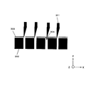
- segmentation tear load The schematic diagram which shows the manufacturing process of a fixed carbon fiber bundle.
- Carbon fibers used in the present invention generally include polyacrylonitrile (PAN) carbon fibers, petroleum / coal pitch carbon fibers, rayon carbon fibers, cellulosic carbon fibers, lignin carbon fibers, phenolic carbon fibers, etc. Are known, but any of these carbon fibers can be suitably used in the present invention. Among them, in the present invention, it is preferable to use polyacrylonitrile (PAN) -based carbon fiber in terms of excellent tensile strength.
- PAN polyacrylonitrile
- PAN polyacrylonitrile
- the carbon fiber used in the present invention may have a sizing agent attached to the surface.
- the type of sizing agent can be appropriately selected according to the type of carbon fiber and thermoplastic matrix resin, and is not particularly limited. .
- the fiber diameter of the single yarn of carbon fiber used in the present invention may be appropriately determined according to the type of carbon fiber, and is not particularly limited.
- the average fiber diameter is usually preferably in the range of 3 ⁇ m to 50 ⁇ m, more preferably in the range of 4 ⁇ m to 12 ⁇ m, and still more preferably in the range of 5 ⁇ m to 8 ⁇ m.
- the said average fiber diameter shall point out the diameter of the single yarn of a carbon fiber. Therefore, when the carbon fiber is in the form of a fiber bundle, it refers not to the diameter of the fiber bundle but to the diameter of the carbon fiber single yarn constituting the fiber bundle.
- the average fiber diameter of carbon fibers can be measured, for example, by the method described in JIS R 7607: 2000. In the present specification, a single yarn may be referred to as a filament.
- the type of fixing agent used in the present invention is not particularly limited as long as it can fix a carbon fiber bundle, but preferably it is solid at normal temperature, more preferably a resin, still more preferably a thermoplastic resin It is.
- the fixative may be only one type, or two or more types.
- the fixing agent When a thermoplastic resin is used as the fixing agent, one having a desired softening point can be appropriately selected and used according to the environment in which the fixed carbon fiber bundle is produced.
- the range of the softening point is not limited, the lower limit value of the preferable softening point is 60 ° C. or more, more preferably 70 ° C. or more, still more preferably 80 ° C. or more.
- the softening point of the fixing agent is preferable because it is solid at room temperature and excellent in handleability even in the use environment at high temperature in summer.
- the upper limit value is 250 ° C. or less, more preferably 180 ° C. or less, still more preferably 150 ° C.
- the contact surface of the heating device can be surface-treated with a material such as PTFE (polytetrafluoroethylene) that is compatible with heat resistance and releasability.
- PTFE polytetrafluoroethylene
- softening temperature refers to the melting temperature when the thermoplastic resin is a crystalline polymer, and is a crystal of DSC (differential scanning calorie) measured from room temperature to 300 ° C at a heating rate of 15 ° C. The peak temperature of the melting curve.
- the melting temperature means the melting point of the thermoplastic resin.
- the softening temperature is defined by the Vicat softening point (JIS K 7206: 2016).
- thermoplastic resins include polyolefin resin, polystyrene resin, polyamide resin, polyester resin, polyacetal resin (polyoxymethylene resin), polycarbonate resin, (meth) acrylic resin, polyarylate resin, polyphenylene ether resin, polyimide resin, Polyether nitrile resin, phenoxy resin, polyphenylene sulfide resin, polysulfone resin, polyketone resin, polyether ketone resin, thermoplastic urethane resin fluorine resin, thermoplastic polybenzimidazole resin and the like can be mentioned.
- polystyrene resin examples include polyethylene resin, polypropylene resin, polybutadiene resin, polymethylpentene resin, vinyl chloride resin, vinylidene chloride resin, vinyl acetate resin, polyvinyl alcohol resin and the like.
- polystyrene resin examples include polystyrene resin, acrylonitrile-styrene resin (AS resin), acrylonitrile-butadiene-styrene resin (ABS resin) and the like.
- polyamide resin examples include polyamide 6 resin (nylon 6), polyamide 11 resin (nylon 11), polyamide 12 resin (nylon 12), polyamide 46 resin (nylon 46), polyamide 66 resin (nylon 66), polyamide 610 Resin (nylon 610), copolyamide etc.
- polyester resin examples include polyethylene terephthalate resin, polyethylene naphthalate resin, polybutylene terephthalate resin, polytrimethylene terephthalate resin, and liquid crystal polyester.
- acrylic resin polymethyl methacrylate can be mentioned, for example.
- polyphenylene ether resin a modified polyphenylene ether etc. can be mentioned, for example.
- polyimide resin examples include thermoplastic polyimide, polyamide imide resin, and polyether imide resin.
- polysulfone resin modified polysulfone resin, polyether sulfone resin etc. can be mentioned, for example.
- polyether ketone resin polyether ketone resin, polyether ether ketone resin, polyether ketone ketone resin can be mentioned, for example.
- fluorine resin a polytetrafluoroethylene etc. can be mentioned, for example.
- thermoplastic resins having different softening points are used in combination
- thermoplastic resins having different average molecular weights in combination are used, etc. You can, but not this.
- the fixing agent is preferably in the form of a powder (powder) having a median diameter of 5 ⁇ m to 300 ⁇ m. Furthermore, it is preferable that the average distance between single filaments of the carbon fiber bundle is smaller than the median diameter of the fixative.
- the fixing agent can not enter the inside of the carbon fiber bundle, and only the surface of the obtained fixed carbon fiber bundle is fixed with the fixing agent, Internal cohesion can be reduced. That is, in the fixed carbon fiber bundle, the fixing agent can be unevenly distributed on one side or both sides (a fixed carbon fiber bundle in which the fixing agent does not exist inside the carbon fiber bundle can be used).
- the fixed carbon fiber bundle of the present invention has the advantage of easy control of the bundle / single yarn distribution.
- the fixative is attached to at least one side of the carbon fiber bundle. Preferably, it is 50% or more on one side, more preferably 70% or more on one side, and still more preferably 80% or more on one side.
- the fixing agent may be attached to both sides.
- “one side” means one side of the carbon fiber bundle viewed from the thickness direction. Since the average thickness of the fixed carbon fiber bundle in the present invention is 180 ⁇ m or less, in many cases, the cross-sectional shape of the fixed short fiber bundle is flat, and one side of the carbon fiber bundle can be clearly seen.
- the preferred embodiment of the present invention is A fixed carbon fiber bundle having a fixing agent attached thereto,
- the fixative adheres to at least 50% of the area of one side of the carbon fiber bundle,
- the average thickness of the fixed carbon fiber bundle is 180 ⁇ m or less, It is a fixed carbon fiber bundle whose separation splitting load is 0.02 N or more and 1.00 N or less.
- the weight ratio of the fixing agent contained in the fixed carbon fiber bundle is preferably 0.5% or more and 30% or less with respect to the whole fixed carbon fiber bundle.
- the lower limit of the weight ratio of the fixing agent is more preferably 1% or more, still more preferably 2% or more, still more preferably 3% or more, based on the whole fixed carbon fiber bundle.
- the upper limit of the weight ratio of the fixing agent is more preferably 20% or less, still more preferably 15% or less, still more preferably 10% or less, based on the whole fixed carbon fiber bundle.
- the fixative By setting the fixative to 30% or less, the fixative is reduced relative to the ratio of the matrix resin (preferably a thermoplastic matrix resin having a higher softening point than the fixative) in the composite material. Even when using a fixing agent having a low softening point, heat resistance can be secured.
- the matrix resin preferably a thermoplastic matrix resin having a higher softening point than the fixative
- the average thickness of the fixed carbon fiber bundle in the present invention is 180 ⁇ m or less.
- the average thickness of the fixed carbon fiber bundle in the present invention is preferably 150 ⁇ m or less, more preferably 120 ⁇ m or less. If it is the said thickness, it is easy to make the fixed carbon fiber bundle impregnate the thermoplastic matrix resin mentioned later.
- splitting and tearing load of fixed carbon fiber bundle The ease of splitting of fixed carbon fiber bundle can be expressed by tearing load.
- the separation tear load of the fiber bundle is 0.02 N or more and 1.00 N or less.
- the lower limit of the splitting tear load is more preferably 0.05 N or more.
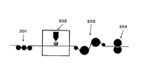
- FIG. 3 shows how the fixed carbon fiber bundle escapes from the blade for separating the fixed carbon fiber bundle.
- the depth indicates the MD (Machine Direction) direction, and the X direction indicates the width direction of the carbon fiber bundle.
- the fixed carbon fiber bundle (303 in FIG. 3) is divided by the upper blade (301) and the lower blade (302), but when the separation tear load of fixed carbon fiber is low, fixed carbon as shown in 304 in FIG. The fiber bundle escapes from the blade for splitting.
- the upper limit of the separation splitting load is more preferably 0.80 N or less, still more preferably 0.40 N or less.
- the split tear load per unit thickness of the fixed carbon fiber bundle is preferably 0.2 N / mm or more 5 It is not more than 0 N / mm, more preferably not less than 0.2 N / mm and not more than 2.0 N / mm, still more preferably not less than 0.3 N / mm and not more than 1.8 N / mm.
- the fixing agent is attached to the carbon fiber bundle before or after opening the carbon fiber bundle, and after making the average thickness 180 ⁇ m or less, the width and thickness of the carbon fiber bundle
- a method for producing a fixed carbon fiber bundle by fixing wherein the fixing carbon fiber bundle has a fixing agent attached to at least one side (preferably a region of 50% or more of one side) of the carbon fiber bundle, and a splitting tear load It is 0.02N or more and 1.00N or less.
- the fixative is preferably attached to the carbon fiber bundle after opening the carbon fiber bundle.
- the preferred embodiment of the present invention is A fixing agent is attached to a carbon fiber bundle before or after opening the carbon fiber bundle, and after making the average thickness 180 ⁇ m or less, the width and thickness of the carbon fiber bundle are fixed to manufacture a fixed carbon fiber bundle.
- the fixed carbon fiber bundle is a method for producing a fixed carbon fiber bundle in which a fixing agent adheres to at least a region of 50% or more of one surface of the carbon fiber bundle, and a splitting tear load is 0.02 N or more and 1.00 N or less .
- the method of attaching the fixing agent there is no limitation on the method of attaching the fixing agent, but a method which can be uniformly applied uniformly is preferable.
- a powdery agent as a raw material of a fixing agent
- the application method by a spray gun the method of fluid immersion, the method of melt
- the raw material of a fixative is disperse
- the application method by a spray gun, the method of using a coater, the method of dipping a fiber bundle in a solution, etc. are mentioned.
- the method of depositing the fixative is preferably a dry process (a method without using a solvent).
- the fixing agent dry By applying the fixing agent dry, compared with the application of the fixing agent in the wet process (method using a solvent), the step of removing the solvent is unnecessary, and the energy required for fixing the carbon fiber bundle is reduced. be able to.
- the concentration In the case of a wet process, the concentration may change due to evaporation of the solvent during work, and the control of the concentration may be required.
- the dry type it is easy to reuse the fixing agent which has not adhered to the carbon fiber bundle.
- a method for applying a dry fixing agent a method (for example, powder coating) in which the fixing agent is charged and attached to a carbon fiber bundle is preferable.
- the fixing agent can be efficiently attached to the carbon fiber by charging the fixing agent and grounding the carbon fiber by utilizing the potential difference. More specifically, the amount of adhesion to the carbon fiber bundle can be increased relative to the amount of fixing agent supplied, and the adhesion efficiency can be enhanced. More specifically, the deposition efficiency can be increased to 50% to 80%.
- the treatment of the fixing agent by corona discharge can be performed, for example, by applying a high voltage to the corona electrode at the tip of the coating gun, causing corona discharge from the electrode, and charging the paint with ions generated by the discharge.
- the weight ratio of the fixing agent contained in the fixed carbon fiber bundle is 0.5% or more and 30% or less with respect to the whole fixed carbon fiber bundle, the fixing agent is charged and fixed to the carbon fiber bundle. It is particularly preferred to produce carbon fiber bundles.
- the method for fixing the width and thickness of the carbon fiber bundle after attaching the fixing agent to the carbon fiber bundle and setting the average thickness to 180 ⁇ m or less but the fixing agent has a softening point of 60 ° C to 250 ° C.
- the carbon fiber bundle be fixed by melting and solidifying.
- the heating method at the time of melting but there may be mentioned a method of heating by bringing it into contact with a heated fixed bar, a roller or the like, a method of heating without contact using heated air or the like or an infrared heater.
- variety of a carbon fiber bundle means the direction longer than thickness.
- a method of melting and fixing the fixing agent a method of heating by contact with a heating roller or the like in a state where the fixing agent is molten, and a method of heating without contact by an infrared heater or hot air may be mentioned.
- the thickness of a fixed carbon fiber bundle can be made uniform by pressurization. After pressure is applied, a fixed carbon fiber bundle can be manufactured by using a cooling roll or solidifying the fixative by natural cooling.
- Fixing the width and thickness of the carbon fiber bundle is not necessary to completely fix the width and thickness of the carbon fiber bundle, and it is easy to separate in a later step by fixing to keep elasticity in the width direction to some extent It is preferable because That is, in other words, the fixed carbon fiber bundle having a separation splitting load of 0.02 N or more and 1.00 N or less is also an index indicating the degree of fixation of the width and thickness of the carbon fiber bundle.
- the fixed carbon fiber bundle may have a tear load of 0.02 N or more and 1.00 N or less.
- the fixed carbon fiber bundle in the present invention is preferably divided to produce two or more divided fixed carbon fiber bundles.
- a separation method such as may be used.
- split fixed carbon fiber bundle (herein sometimes referred to as split fixed carbon fiber bundle) be cut to produce a discontinuous split fixed carbon fiber bundle.
- the fixed carbon fiber bundle length of the obtained discontinuous divided fixed carbon fiber bundle is evaluated by weight average fixed carbon fiber bundle length.
- the weight-averaged fixed carbon fiber bundle length can be determined, for example, by measuring the individual lengths of 100 discontinuous fixed carbon fiber bundles randomly extracted to 1 mm using a caliper or the like.
- the composite material in the present invention can be prepared by impregnating a fixed carbon fiber bundle or a discontinuous divided fixed carbon fiber bundle with a thermoplastic matrix resin.
- the fixed carbon fiber bundle is not called a composite material.
- the composite material in the present specification is a fixed carbon fiber bundle impregnated with a thermoplastic matrix resin separately from the fixing agent.
- thermoplastic matrix resin As one form of the composite material, it is possible to obtain a unidirectional material by impregnating a thermoplastic matrix resin in a state in which a plurality of fixed carbon fiber bundles or a plurality of divided fixed carbon fiber bundles are arranged in parallel without gaps. At this time, it is preferable that the thermoplastic matrix resin be compatible with the fixative.
- a composite material capable of being formed into a complicated shape is manufactured by impregnating a thermoplastic resin with a discrete fixed-fixed carbon fiber bundle in a mat-like state. it can. In this case, it is possible to obtain a material having isotropy in the in-plane direction (the direction perpendicular to the thickness of the composite material) by randomly dispersing the discrete distribution fixed carbon fiber bundles.
- the split fixed carbon fiber bundle is impregnated with a thermoplastic matrix resin
- the thermoplastic matrix resin to be impregnated is preferably compatible with the fixing agent.
- the impregnation with the thermoplastic matrix resin is to fill the spaces between the fixed carbon fiber bundles and the filaments in the fixed carbon fiber bundles with the thermoplastic matrix resin, but it is not necessary to be completely filled. An air gap may remain in the part.
- the carbon fiber volume ratio (hereinafter sometimes simply referred to as “Vf”) defined in the following formula (c) is not particularly limited, but the carbon fiber volume ratio (Vf) is 10 to 60% is preferable, 20 to 50% is more preferable, and 25 to 45% is more preferable.
- Carbon fiber volume ratio (Vf) 100 ⁇ carbon fiber volume / (carbon fiber volume + fixing agent volume + thermoplastic matrix resin volume) (c)
- thermoplastic matrix resin used for the composite material of the present invention is not particularly limited, and one having a desired softening point or melting point can be appropriately selected and used.
- thermoplastic matrix resin one having a softening point in the range of 180 ° C. to 350 ° C. is usually used, but it is not limited thereto.
- Molded body It is preferable to press-mold a composite material produced by impregnating a discontinuous separation-fixed carbon fiber bundle with a thermoplastic matrix resin to produce a molded body.
- a preferable press-forming method for producing a molded body compression molding using a cold press or a hot press is used.
- the cold pressing method includes at least the following steps A-1) to A-3).
- Step A-1) A step of heating the composite material to a temperature higher than the softening temperature of the thermoplastic matrix resin contained in the composite material.
- Step A-2) A step of arranging the heated composite material obtained in the above step A-1) in a mold in which the thermoplastic matrix resin is temperature-controlled to a temperature lower than the softening temperature.
- Step A-3) A step of pressing and molding the composite material disposed in the mold in the step A-2).
- the hot press method includes at least the following steps B-1) to B-3).
- Step B-1) Step of placing the composite material in the mold step B-2) Step of raising the temperature of the mold to a temperature higher than the softening temperature of the thermoplastic matrix resin and pressing it Step B-3) Of the thermoplastic matrix resin Process of molding by controlling the temperature of the mold below the softening point
- the composite material When feeding into the mold, the composite material may be used singly (in one sheet) or plural sheets in accordance with the thickness of the target molded body.
- process A-3) and process B-2 are processes of applying a pressure to a composite material and obtaining the molded object of a desired shape, although there is no limitation in particular about the molding pressure at this time, less than 30 MPa
- the pressure is preferably 20 MPa or less, more preferably 10 MPa or less.
- various steps may be inserted between the above steps at the time of press forming, for example, vacuum compression forming may be used while press forming while applying a vacuum.
- the raw materials used in the following production examples and examples are as follows.
- the decomposition temperature is a measurement result by thermogravimetric analysis.
- Fixing agent 1 Copolymerized nylon "VESTAMELT” (registered trademark) Hylink manufactured by Daicel Evonik, thermoplastic resin, melting point 126 ° C.
- Fixing agent 2 Copolymerized nylon "VESTAMELT” (registered trademark) 250-P1 manufactured by Daicel Evonik Co., thermoplastic resin, melting point 123 ° C.
- Fixative 3 The polyamide particles described in Example 3 of WO 2013/133421 were used.
- Polyamide 6 Hereinafter, sometimes abbreviated as PA6. Crystalline resin, melting point 225 ° C, decomposition temperature (in air) 300 ° C
- the electrification of the fixative agent is carried out using a corona discharger provided in an automatic gun for electrostatic powder coating (GX 531N made by Parker Engineering Co., Ltd.), applying a high voltage to the corona discharge electrode to generate ions from the electrode
- the fixative was charged by passing the fixative there.
- the voltage for charging was 50 kV.
- the fixing agent After applying a fixing agent to the carbon fiber bundle, the fixing agent is heated and melted by a 30 kW infrared heater (manufactured by NGK Kilntech Co., Ltd.), and solidified after cooling and solidifying to obtain a fixed carbon fiber bundle.
- a 30 kW infrared heater manufactured by NGK Kilntech Co., Ltd.
- the average inter-yarn distance is the number of single yarns contained in the carbon fiber (Mi), the width of the carbon fiber bundle (Wi ⁇ m), and the carbon fiber for the carbon fiber bundle before applying the fixative.
- the bundle thickness (Ti ⁇ m) and the fiber diameter (Di ⁇ m) were used to calculate from the following equation (b).
- Average distance between single yarns ( ⁇ m) Wi / (Mi / (Ti / Di))-Di (b)
- the width of the carbon fiber bundle was measured by a ruler (manufactured by Shinwa Measurement Co., Ltd.), and the thickness was measured by a micrometer (manufactured by Mitutoyo).
- the median diameter (D50) of various fixatives was measured using a laser diffraction scattering particle size distribution analyzer (LA-960 manufactured by Horiba, Ltd.).
- Adhesion area of fixative on one side of fixed carbon fiber bundle (%)
- the adhesion area of the fixing agent on one side can be measured by cross-sectional observation of the cut surface of the fixed carbon fiber bundle. Specifically, the fixed carbon fiber bundle is cut in the width direction, and the cut surface is observed with a microscope.
- the length (Lr) on the cross section where the fixing agent exists on the outermost surface and the length (Lf) on the cross section where carbon fibers exist on the outermost surface are represented by the following formula be able to. Ignore the gap.
- Adhesion area of fixative on one side 100 ⁇ Lr / (Lr + Lf)
- region is evaluated by the average value of the measured value at the time of ten-point observation.
- Example 1 51%
- Example 2 77%
- Example 3 80%
- Example 4 100%
- Example 5 100%
- Adhesion efficiency The adhesion efficiency of the fixative agent is determined using the weight Wa (kg) of the fixative agent applied (supplied) from the coating apparatus and the weight Wb (kg) of the fixative agent actually attached to the carbon fiber bundle, as described below Calculated by the equation.
- Adhesion efficiency (%) Wb / Wa ⁇ 100
- -Average thickness of fixed carbon fiber bundle 20 thickness of a sample is measured at intervals of 5 m using a Mitutoyo Micrometer, and the average value of each measurement value is taken as the average thickness of the fixed carbon fiber bundle.
- a fixed carbon fiber bundle having a length of 10 m is prepared, and obtained by dividing it with a score type separation device using 11 blades set at a distance of 2 mm. Also, the first 300 mm (area of 300 mm in the length direction from the end where the blade contacts the blade first) is observed for the separation fixed carbon fiber bundle, and the fiber width is evaluated. Specifically, it is as follows. Fiber width of the widest split fixed carbon fiber bundle is less than 3 mm: Good Fiber width of the widest split fixed carbon fiber bundle is 3 mm or more: Bad
- Example 1 25 lines
- Example 2 5 lines
- Example 7 4 lines
- Example 8 1 Example 1 and 2 in which the application method of the fixing agent is dry
- Example 1 and 2 are in contrast to Examples 7 and 8 in which the fixing agent is wet
- more single yarns are generated, which is preferable from the viewpoint of easy generation of bundles and single yarns.
- Example 1 As carbon fiber, carbon fiber “tenax” (registered trademark) STS40-24K (average fiber diameter 7 ⁇ m, number of single fibers 24,000) manufactured by Teijin Ltd. is used, and the thickness of carbon fiber bundle is about 100 ⁇ m. A 10 mm wide carbon fiber bundle was opened to a width of 20 mm. The average interfilamentary distance of the opened carbon fiber bundle was 2.8 ⁇ m. A powdery co-polymerized nylon "VESTAMELT” (registered trademark) Hylink manufactured by Daicel Evonik Co., Ltd. was applied thereto as a fixing agent, and was solidified by solidification to fix the opened state of the carbon fiber bundle. The median diameter of the powdery fixative was 47.1 ⁇ m.
- the weight ratio of the fixing agent contained in the fixed carbon fiber bundle was 2.0%.
- the split tear load of this fixed carbon fiber bundle was measured, and it was 0.07N.
- the average thickness of the produced fixed carbon fiber bundle was 140 ⁇ m.
- the adhesion area of the fixing agent was 100% on one side of the carbon fiber bundle (the surface to which the fixing agent was applied).
- the fixed carbon fiber bundle was divided into 20 (20 bundles) by a micro slitter so as to be 1 mm wide in the width direction. The results are shown in Table 1.
- Examples 2 and 3 A fixed carbon fiber bundle was produced in the same manner as in Example 1 except that the weight ratio of the fixing agent was changed to 4.5% and 14.2% of the whole fixed carbon fiber bundle, respectively. The results are shown in Table 1.
- Examples 4 and 5 A fixed carbon fiber bundle is manufactured in the same manner as in Example 1 except that the weight ratio of the fixing agent is set to 20.0% and 30.0% of the whole fixed carbon fiber bundle, respectively. The results are shown in Table 1.
- Example 6 A fixed carbon fiber bundle is manufactured in the same manner as in Example 1 except that the fixing agent is a copolyamide nylon "VESTAMELT” (registered trademark) 250-P1 manufactured by Daicel-Evonik. The results are shown in Table 1.
- Example 7 A fixed carbon fiber bundle is manufactured in the same manner as in Example 1 except that the fixing agent 3 is used for wet coating. The results are shown in Table 1.
- Example 8 A fixed carbon fiber bundle is produced in the same manner as in Example 7 except that the weight ratio of the fixing agent is 4.5%. The results are shown in Table 1.
- Example 9 A fixed carbon fiber bundle is produced in the same manner as in Example 1 except that the fixing agent is applied without being charged. Two times as much fixative as in Example 1 is provided to deposit the same amount. The results are shown in Table 1.
- Example 10 The fixative is supplied as in Example 9 except that the fixative is wet applied. Concentration control is difficult, and stable production is difficult even when trying to make a fixed carbon fiber bundle with a length of 100 m. The results are shown in Table 1.
- Comparative Example 1 As carbon fiber, carbon fiber “tenax” (registered trademark) STS40-24K (average fiber diameter 7 ⁇ m, number of single fibers 24,000) manufactured by Teijin Ltd. is used, and the thickness of carbon fiber bundle is about 100 ⁇ m. A 10 mm wide carbon fiber bundle was opened to a width of 20 mm. Subsequently, the carbon fiber bundle was divided into 20 (20 bundles) by a micro slitter so as to be 1 mm wide in the width direction. Since the carbon fiber bundle is not fixed and the separated carbon fiber bundle returns to the state of the carbon fiber bundle before the separation even if the separation is performed, the stability of the separation is Bad. The results are shown in Table 1.
- the fixed carbon fiber bundle of the present invention can be stably divided and is suitable for producing a stable performance composite material.
- This composite material can be used for various components, for example, structural members of automobiles, various electric products, frames and casings of machines, etc., for all parts where impact absorption is desired. Preferably, it can be used as an automobile part.
Landscapes
- Engineering & Computer Science (AREA)
- Chemical & Material Sciences (AREA)
- Textile Engineering (AREA)
- Chemical Kinetics & Catalysis (AREA)
- Mechanical Engineering (AREA)
- Polymers & Plastics (AREA)
- Health & Medical Sciences (AREA)
- Medicinal Chemistry (AREA)
- Materials Engineering (AREA)
- Organic Chemistry (AREA)
- Manufacturing & Machinery (AREA)
- Reinforced Plastic Materials (AREA)
- Treatments For Attaching Organic Compounds To Fibrous Goods (AREA)
- Chemical Or Physical Treatment Of Fibers (AREA)
- Yarns And Mechanical Finishing Of Yarns Or Ropes (AREA)
Priority Applications (3)
| Application Number | Priority Date | Filing Date | Title |
|---|---|---|---|
| JP2019543510A JP6875538B2 (ja) | 2017-09-21 | 2018-08-29 | 固定炭素繊維束の製造方法 |
| EP18859351.1A EP3686331B1 (de) | 2017-09-21 | 2018-08-29 | Festes kohlenstofffaserbündel und verfahren zur herstellung eines festen kohlenstofffaserbündels |
| US16/647,230 US12018410B2 (en) | 2017-09-21 | 2018-08-29 | Fixed carbon fiber bundle and method for producing fixed carbon fiber bundle |
Applications Claiming Priority (2)
| Application Number | Priority Date | Filing Date | Title |
|---|---|---|---|
| JP2017180992 | 2017-09-21 | ||
| JP2017-180992 | 2017-09-21 |
Publications (1)
| Publication Number | Publication Date |
|---|---|
| WO2019058910A1 true WO2019058910A1 (ja) | 2019-03-28 |
Family
ID=65811271
Family Applications (1)
| Application Number | Title | Priority Date | Filing Date |
|---|---|---|---|
| PCT/JP2018/031987 WO2019058910A1 (ja) | 2017-09-21 | 2018-08-29 | 固定炭素繊維束、及び固定炭素繊維束の製造方法 |
Country Status (4)
| Country | Link |
|---|---|
| US (1) | US12018410B2 (de) |
| EP (1) | EP3686331B1 (de) |
| JP (1) | JP6875538B2 (de) |
| WO (1) | WO2019058910A1 (de) |
Cited By (1)
| Publication number | Priority date | Publication date | Assignee | Title |
|---|---|---|---|---|
| WO2021251205A1 (ja) * | 2020-06-09 | 2021-12-16 | 三菱ケミカル株式会社 | スリット入り炭素繊維束の製造方法、炭素繊維パッケージおよび炭素繊維パッケージの製造方法 |
Citations (9)
| Publication number | Priority date | Publication date | Assignee | Title |
|---|---|---|---|---|
| JPH0457974A (ja) * | 1990-06-25 | 1992-02-25 | Idemitsu Kosan Co Ltd | ポリシアノアリールエーテル被覆炭素繊維とその製造方法 |
| JP2008297670A (ja) * | 2007-05-31 | 2008-12-11 | Sakai Ovex Co Ltd | 分繊糸織物の製造方法および分繊糸織物 |
| WO2013133421A1 (ja) | 2012-03-09 | 2013-09-12 | 帝人株式会社 | 炭素繊維束及びその製造方法 |
| JP2015218417A (ja) | 2014-05-21 | 2015-12-07 | 株式会社ハーモニ産業 | 開繊繊維束の目止め処理装置、目止め処理方法及び目止め処理された開繊繊維束 |
| JP2016003412A (ja) * | 2014-06-16 | 2016-01-12 | 帝人株式会社 | サイジング剤付着繊維束およびその製造方法 |
| JP2016509638A (ja) * | 2013-01-28 | 2016-03-31 | トウホウ テナックス ユーロップ ゲゼルシャフト ミット ベシュレンクテル ハフツングToho Tenax Europe GmbH | 含浸された補強用繊維ヤーン及び複合材料を製造するためのその使用 |
| JP2016060976A (ja) * | 2014-09-16 | 2016-04-25 | 三菱レイヨン株式会社 | 強化繊維束、繊維強化熱可塑性樹脂組成物およびその成形品 |
| WO2016104154A1 (ja) * | 2014-12-26 | 2016-06-30 | 東レ株式会社 | 部分分繊繊維束の製造方法および製造装置、部分分繊繊維束 |
| JP2017180992A (ja) | 2016-03-31 | 2017-10-05 | 明智セラミックス株式会社 | 溶融炉の炉底構造 |
Family Cites Families (12)
| Publication number | Priority date | Publication date | Assignee | Title |
|---|---|---|---|---|
| JPH01292038A (ja) | 1988-05-19 | 1989-11-24 | Toray Ind Inc | 開繊性の優れた無撚炭素繊維束、その製造法および製造装置 |
| DE69526997T2 (de) | 1994-03-31 | 2003-01-23 | Toray Industries, Inc. | Prepreg-Pröcursor aus kohlenfasergeweben Prepregs und Verfahren zu deren Herstellung |
| JP3440616B2 (ja) | 1994-03-31 | 2003-08-25 | 東レ株式会社 | 炭素繊維織物、プリプレグ、繊維強化複合材料、およびそれらの製造方法 |
| US5756206A (en) * | 1995-03-15 | 1998-05-26 | Custom Composite Materials, Inc. | Flexible low bulk pre-impregnated tow |
| JPH0938972A (ja) | 1995-07-31 | 1997-02-10 | Sekisui Chem Co Ltd | 繊維複合シートの製造方法 |
| JP3927795B2 (ja) | 2001-11-29 | 2007-06-13 | 三菱レイヨン株式会社 | 炭素繊維束とその繊維織物 |
| JP4068938B2 (ja) | 2002-10-02 | 2008-03-26 | サカイオーベックス株式会社 | 開繊糸の開繊幅安定化方法 |
| JP4443148B2 (ja) | 2003-01-07 | 2010-03-31 | 三菱レイヨン株式会社 | 炭素繊維束及びチョップド炭素繊維束及びその製造方法、並びに炭素繊維強化熱可塑性樹脂組成物及びその成形品 |
| JP2007216432A (ja) | 2006-02-14 | 2007-08-30 | Fukui Prefecture | 一方向強化繊維シート及びその製造方法 |
| JP5996320B2 (ja) | 2012-08-01 | 2016-09-21 | 帝人株式会社 | ランダムマットの製造方法 |
| JPWO2015194457A1 (ja) * | 2014-06-16 | 2017-04-20 | 帝人株式会社 | 強化繊維束およびその製造方法 |
| KR20170081117A (ko) | 2015-12-31 | 2017-07-11 | 코오롱플라스틱 주식회사 | 섬유강화 복합재료 시트의 제조방법 및 섬유강화 복합재료 시트 |
-
2018
- 2018-08-29 WO PCT/JP2018/031987 patent/WO2019058910A1/ja unknown
- 2018-08-29 US US16/647,230 patent/US12018410B2/en active Active
- 2018-08-29 EP EP18859351.1A patent/EP3686331B1/de active Active
- 2018-08-29 JP JP2019543510A patent/JP6875538B2/ja active Active
Patent Citations (9)
| Publication number | Priority date | Publication date | Assignee | Title |
|---|---|---|---|---|
| JPH0457974A (ja) * | 1990-06-25 | 1992-02-25 | Idemitsu Kosan Co Ltd | ポリシアノアリールエーテル被覆炭素繊維とその製造方法 |
| JP2008297670A (ja) * | 2007-05-31 | 2008-12-11 | Sakai Ovex Co Ltd | 分繊糸織物の製造方法および分繊糸織物 |
| WO2013133421A1 (ja) | 2012-03-09 | 2013-09-12 | 帝人株式会社 | 炭素繊維束及びその製造方法 |
| JP2016509638A (ja) * | 2013-01-28 | 2016-03-31 | トウホウ テナックス ユーロップ ゲゼルシャフト ミット ベシュレンクテル ハフツングToho Tenax Europe GmbH | 含浸された補強用繊維ヤーン及び複合材料を製造するためのその使用 |
| JP2015218417A (ja) | 2014-05-21 | 2015-12-07 | 株式会社ハーモニ産業 | 開繊繊維束の目止め処理装置、目止め処理方法及び目止め処理された開繊繊維束 |
| JP2016003412A (ja) * | 2014-06-16 | 2016-01-12 | 帝人株式会社 | サイジング剤付着繊維束およびその製造方法 |
| JP2016060976A (ja) * | 2014-09-16 | 2016-04-25 | 三菱レイヨン株式会社 | 強化繊維束、繊維強化熱可塑性樹脂組成物およびその成形品 |
| WO2016104154A1 (ja) * | 2014-12-26 | 2016-06-30 | 東レ株式会社 | 部分分繊繊維束の製造方法および製造装置、部分分繊繊維束 |
| JP2017180992A (ja) | 2016-03-31 | 2017-10-05 | 明智セラミックス株式会社 | 溶融炉の炉底構造 |
Non-Patent Citations (1)
| Title |
|---|
| See also references of EP3686331A4 |
Cited By (2)
| Publication number | Priority date | Publication date | Assignee | Title |
|---|---|---|---|---|
| WO2021251205A1 (ja) * | 2020-06-09 | 2021-12-16 | 三菱ケミカル株式会社 | スリット入り炭素繊維束の製造方法、炭素繊維パッケージおよび炭素繊維パッケージの製造方法 |
| TWI823098B (zh) * | 2020-06-09 | 2023-11-21 | 日商三菱化學股份有限公司 | 導入切口之碳纖維束之製造方法、碳纖維捲裝物及碳纖維捲裝物之製造方法 |
Also Published As
| Publication number | Publication date |
|---|---|
| EP3686331A1 (de) | 2020-07-29 |
| JP6875538B2 (ja) | 2021-05-26 |
| EP3686331B1 (de) | 2021-10-20 |
| US20210054543A1 (en) | 2021-02-25 |
| EP3686331A4 (de) | 2020-11-11 |
| US12018410B2 (en) | 2024-06-25 |
| JPWO2019058910A1 (ja) | 2020-03-26 |
Similar Documents
| Publication | Publication Date | Title |
|---|---|---|
| EP2716433B1 (de) | Verfahren zur herstellung von presslingen mit verzögerter isotropie | |
| US20200332077A1 (en) | Random Mat and Fiber-Reinforced Composite Material Shaped Product | |
| JP5702854B2 (ja) | 強化繊維複合材料 | |
| KR102021629B1 (ko) | 랜덤 매트 및 섬유 강화 복합재료 | |
| CN110072693B (zh) | 复合结构体及其制造方法 | |
| JP5944114B2 (ja) | 熱可塑等方性プリプレグ | |
| US9884954B2 (en) | Random mat and fiber-reinforced composite material shaped product | |
| US10208174B2 (en) | Random mat and fiber-reinforced composite material shaped product | |
| WO2012105080A1 (ja) | ランダムマット、および強化繊維複合材料 | |
| JP2011178890A (ja) | 炭素繊維複合材料 | |
| WO2019058910A1 (ja) | 固定炭素繊維束、及び固定炭素繊維束の製造方法 | |
| JP6421300B2 (ja) | 炭素繊維強化樹脂押出材及びその製造方法 | |
| JP6092923B2 (ja) | 炭素繊維複合材料 | |
| CN117062857A (zh) | 预浸料坯层叠体及复合结构体以及复合结构体的制造方法 | |
| JP2013052602A (ja) | 表面が平滑で均一な厚みを有する成形体およびその製造方法 |
Legal Events
| Date | Code | Title | Description |
|---|---|---|---|
| 121 | Ep: the epo has been informed by wipo that ep was designated in this application |
Ref document number: 18859351 Country of ref document: EP Kind code of ref document: A1 |
|
| ENP | Entry into the national phase |
Ref document number: 2019543510 Country of ref document: JP Kind code of ref document: A |
|
| NENP | Non-entry into the national phase |
Ref country code: DE |
|
| ENP | Entry into the national phase |
Ref document number: 2018859351 Country of ref document: EP Effective date: 20200421 |