WO2019058805A1 - 機器温調装置 - Google Patents
機器温調装置 Download PDFInfo
- Publication number
- WO2019058805A1 WO2019058805A1 PCT/JP2018/029938 JP2018029938W WO2019058805A1 WO 2019058805 A1 WO2019058805 A1 WO 2019058805A1 JP 2018029938 W JP2018029938 W JP 2018029938W WO 2019058805 A1 WO2019058805 A1 WO 2019058805A1
- Authority
- WO
- WIPO (PCT)
- Prior art keywords
- temperature
- refrigerant
- condenser
- target
- working fluid
- Prior art date
- Legal status (The legal status is an assumption and is not a legal conclusion. Google has not performed a legal analysis and makes no representation as to the accuracy of the status listed.)
- Ceased
Links
Images


Classifications
-
- B—PERFORMING OPERATIONS; TRANSPORTING
- B60—VEHICLES IN GENERAL
- B60H—ARRANGEMENTS OF HEATING, COOLING, VENTILATING OR OTHER AIR-TREATING DEVICES SPECIALLY ADAPTED FOR PASSENGER OR GOODS SPACES OF VEHICLES
- B60H1/00—Heating, cooling or ventilating devices
- B60H1/22—Heating, cooling or ventilating devices the heat source being other than the propulsion plant
-
- B—PERFORMING OPERATIONS; TRANSPORTING
- B60—VEHICLES IN GENERAL
- B60K—ARRANGEMENT OR MOUNTING OF PROPULSION UNITS OR OF TRANSMISSIONS IN VEHICLES; ARRANGEMENT OR MOUNTING OF PLURAL DIVERSE PRIME-MOVERS IN VEHICLES; AUXILIARY DRIVES FOR VEHICLES; INSTRUMENTATION OR DASHBOARDS FOR VEHICLES; ARRANGEMENTS IN CONNECTION WITH COOLING, AIR INTAKE, GAS EXHAUST OR FUEL SUPPLY OF PROPULSION UNITS IN VEHICLES
- B60K1/00—Arrangement or mounting of electrical propulsion units
- B60K1/04—Arrangement or mounting of electrical propulsion units of the electric storage means for propulsion
-
- B—PERFORMING OPERATIONS; TRANSPORTING
- B60—VEHICLES IN GENERAL
- B60K—ARRANGEMENT OR MOUNTING OF PROPULSION UNITS OR OF TRANSMISSIONS IN VEHICLES; ARRANGEMENT OR MOUNTING OF PLURAL DIVERSE PRIME-MOVERS IN VEHICLES; AUXILIARY DRIVES FOR VEHICLES; INSTRUMENTATION OR DASHBOARDS FOR VEHICLES; ARRANGEMENTS IN CONNECTION WITH COOLING, AIR INTAKE, GAS EXHAUST OR FUEL SUPPLY OF PROPULSION UNITS IN VEHICLES
- B60K11/00—Arrangement in connection with cooling of propulsion units
- B60K11/02—Arrangement in connection with cooling of propulsion units with liquid cooling
- B60K11/04—Arrangement or mounting of radiators, radiator shutters, or radiator blinds
-
- F—MECHANICAL ENGINEERING; LIGHTING; HEATING; WEAPONS; BLASTING
- F28—HEAT EXCHANGE IN GENERAL
- F28D—HEAT-EXCHANGE APPARATUS, NOT PROVIDED FOR IN ANOTHER SUBCLASS, IN WHICH THE HEAT-EXCHANGE MEDIA DO NOT COME INTO DIRECT CONTACT
- F28D15/00—Heat-exchange apparatus with the intermediate heat-transfer medium in closed tubes passing into or through the conduit walls ; Heat-exchange apparatus employing intermediate heat-transfer medium or bodies
- F28D15/02—Heat-exchange apparatus with the intermediate heat-transfer medium in closed tubes passing into or through the conduit walls ; Heat-exchange apparatus employing intermediate heat-transfer medium or bodies in which the medium condenses and evaporates, e.g. heat pipes
- F28D15/06—Control arrangements therefor
-
- H—ELECTRICITY
- H01—ELECTRIC ELEMENTS
- H01M—PROCESSES OR MEANS, e.g. BATTERIES, FOR THE DIRECT CONVERSION OF CHEMICAL ENERGY INTO ELECTRICAL ENERGY
- H01M10/00—Secondary cells; Manufacture thereof
- H01M10/60—Heating or cooling; Temperature control
- H01M10/61—Types of temperature control
- H01M10/613—Cooling or keeping cold
-
- H—ELECTRICITY
- H01—ELECTRIC ELEMENTS
- H01M—PROCESSES OR MEANS, e.g. BATTERIES, FOR THE DIRECT CONVERSION OF CHEMICAL ENERGY INTO ELECTRICAL ENERGY
- H01M10/00—Secondary cells; Manufacture thereof
- H01M10/60—Heating or cooling; Temperature control
- H01M10/61—Types of temperature control
- H01M10/617—Types of temperature control for achieving uniformity or desired distribution of temperature
-
- H—ELECTRICITY
- H01—ELECTRIC ELEMENTS
- H01M—PROCESSES OR MEANS, e.g. BATTERIES, FOR THE DIRECT CONVERSION OF CHEMICAL ENERGY INTO ELECTRICAL ENERGY
- H01M10/00—Secondary cells; Manufacture thereof
- H01M10/60—Heating or cooling; Temperature control
- H01M10/62—Heating or cooling; Temperature control specially adapted for specific applications
- H01M10/625—Vehicles
-
- H—ELECTRICITY
- H01—ELECTRIC ELEMENTS
- H01M—PROCESSES OR MEANS, e.g. BATTERIES, FOR THE DIRECT CONVERSION OF CHEMICAL ENERGY INTO ELECTRICAL ENERGY
- H01M10/00—Secondary cells; Manufacture thereof
- H01M10/60—Heating or cooling; Temperature control
- H01M10/63—Control systems
- H01M10/633—Control systems characterised by algorithms, flow charts, software details or the like
-
- H—ELECTRICITY
- H01—ELECTRIC ELEMENTS
- H01M—PROCESSES OR MEANS, e.g. BATTERIES, FOR THE DIRECT CONVERSION OF CHEMICAL ENERGY INTO ELECTRICAL ENERGY
- H01M10/00—Secondary cells; Manufacture thereof
- H01M10/60—Heating or cooling; Temperature control
- H01M10/64—Heating or cooling; Temperature control characterised by the shape of the cells
- H01M10/647—Prismatic or flat cells, e.g. pouch cells
-
- H—ELECTRICITY
- H01—ELECTRIC ELEMENTS
- H01M—PROCESSES OR MEANS, e.g. BATTERIES, FOR THE DIRECT CONVERSION OF CHEMICAL ENERGY INTO ELECTRICAL ENERGY
- H01M10/00—Secondary cells; Manufacture thereof
- H01M10/60—Heating or cooling; Temperature control
- H01M10/65—Means for temperature control structurally associated with the cells
- H01M10/655—Solid structures for heat exchange or heat conduction
- H01M10/6552—Closed pipes transferring heat by thermal conductivity or phase transition, e.g. heat pipes
-
- H—ELECTRICITY
- H01—ELECTRIC ELEMENTS
- H01M—PROCESSES OR MEANS, e.g. BATTERIES, FOR THE DIRECT CONVERSION OF CHEMICAL ENERGY INTO ELECTRICAL ENERGY
- H01M10/00—Secondary cells; Manufacture thereof
- H01M10/60—Heating or cooling; Temperature control
- H01M10/65—Means for temperature control structurally associated with the cells
- H01M10/655—Solid structures for heat exchange or heat conduction
- H01M10/6556—Solid parts with flow channel passages or pipes for heat exchange
-
- H—ELECTRICITY
- H01—ELECTRIC ELEMENTS
- H01M—PROCESSES OR MEANS, e.g. BATTERIES, FOR THE DIRECT CONVERSION OF CHEMICAL ENERGY INTO ELECTRICAL ENERGY
- H01M10/00—Secondary cells; Manufacture thereof
- H01M10/60—Heating or cooling; Temperature control
- H01M10/65—Means for temperature control structurally associated with the cells
- H01M10/656—Means for temperature control structurally associated with the cells characterised by the type of heat-exchange fluid
- H01M10/6569—Fluids undergoing a liquid-gas phase change or transition, e.g. evaporation or condensation
-
- H—ELECTRICITY
- H01—ELECTRIC ELEMENTS
- H01M—PROCESSES OR MEANS, e.g. BATTERIES, FOR THE DIRECT CONVERSION OF CHEMICAL ENERGY INTO ELECTRICAL ENERGY
- H01M10/00—Secondary cells; Manufacture thereof
- H01M10/60—Heating or cooling; Temperature control
- H01M10/66—Heat-exchange relationships between the cells and other systems, e.g. central heating systems or fuel cells
- H01M10/663—Heat-exchange relationships between the cells and other systems, e.g. central heating systems or fuel cells the system being an air-conditioner or an engine
-
- Y—GENERAL TAGGING OF NEW TECHNOLOGICAL DEVELOPMENTS; GENERAL TAGGING OF CROSS-SECTIONAL TECHNOLOGIES SPANNING OVER SEVERAL SECTIONS OF THE IPC; TECHNICAL SUBJECTS COVERED BY FORMER USPC CROSS-REFERENCE ART COLLECTIONS [XRACs] AND DIGESTS
- Y02—TECHNOLOGIES OR APPLICATIONS FOR MITIGATION OR ADAPTATION AGAINST CLIMATE CHANGE
- Y02E—REDUCTION OF GREENHOUSE GAS [GHG] EMISSIONS, RELATED TO ENERGY GENERATION, TRANSMISSION OR DISTRIBUTION
- Y02E60/00—Enabling technologies; Technologies with a potential or indirect contribution to GHG emissions mitigation
- Y02E60/10—Energy storage using batteries
Definitions
- the present disclosure relates to an apparatus temperature control device.
- thermoregulator temperature control apparatus of a loop type
- mold is known (for example, refer patent document 1).
- the battery temperature control device described in Patent Document 1 absorbs heat from the battery by an evaporator which is a battery temperature control unit, evaporates the refrigerant in the battery temperature control unit, and heat medium cooling unit for the evaporated refrigerant
- the battery is configured to be cooled by condensation using a condenser.
- the liquid refrigerant in the battery temperature control unit is evaporated by the heating member disposed in the battery temperature control unit, and the evaporated refrigerant is It is configured to warm up the battery by condensing internally.
- Patent Document 1 describes that the battery temperature control device performs cooling and warm-up of the battery, the relationship between the control process and the battery temperature and the working fluid required for cooling and warm-up of the battery. No mention is made about etc.
- the present inventors provide a temperature sensor for detecting the device temperature of a target device such as a battery, and adjust the capabilities of the condenser, the heating member, and the like so that the difference between the device temperature and the predetermined appropriate temperature is reduced. We examined to perform the control processing.
- the temperature change of the target device becomes gentler than the temperature change of the working fluid of the device temperature regulator. Therefore, when the above-described control process is performed, for example, if the calorific value of the target device increases and the difference between the device temperature and the appropriate temperature increases, the temperature of the working fluid near the target device until the device temperature stops rising The temperature of the working fluid may fall too much. In this case, useless power increases as the temperature of the working fluid decreases excessively. In addition, even if the temperature of the working fluid is lowered, the device temperature becomes high, which may cause a decrease in the performance of the target device.
- the target device is cooled by the working fluid whose temperature is excessively lowered.
- the device temperature approaches the appropriate temperature, but since the refrigerant temperature is low, the device temperature may fall excessively below the appropriate temperature.
- the target device is brought close to the appropriate temperature by heating or the like, the temperature of the working fluid may rise excessively, and useless power may increase as the temperature of the working fluid is excessively raised. I will.
- An object of the present disclosure is to provide a device temperature control apparatus capable of appropriately adjusting the temperature of a target device.
- the present disclosure relates to an apparatus temperature control device that adjusts the temperature of at least one target device (BP).
- the device temperature control device A heat exchanger for equipment which absorbs heat from the target equipment to evaporate the liquid working fluid when the target equipment is cooled; At least one condenser for condensing the gaseous working fluid evaporated in the equipment heat exchanger when the target equipment is cooled; A gas passage unit for guiding a gaseous working fluid evaporated in the equipment heat exchanger to the condenser; A liquid passage portion for guiding a liquid working fluid condensed by the condenser to the heat exchanger for equipment; A state quantity detection unit provided at a predetermined location in a fluid circulation circuit including an apparatus heat exchanger, a condenser, a gas passage, and a liquid passage, and detecting a predetermined amount of state of working fluid; And a controller configured to adjust the heat radiation capacity of the condenser such that the difference between the state quantity detected by the state quantity detection unit and the predetermined target state quantity
- the heat radiation capacity of the condenser is adjusted so that the difference between the state quantity of the working fluid and the target state quantity is reduced, the temperature fluctuation of the working fluid is unlikely to be excessive. For this reason, it becomes possible to avoid the hunting of the temperature of the object device accompanying the temperature fluctuation of the working fluid, and to adjust the temperature of the object device appropriately.
- the device temperature control device A device heat exchanger configured to be able to exchange heat between the working fluid and the target device so that the working fluid condenses when the target device is warmed up; An upper side connection portion provided at a portion on the upper side in the direction of gravity of the heat exchanger for equipment; A lower connection portion provided at a position lower than the upper connection portion in the direction of gravity of the heat exchanger for equipment; A communication passage portion communicating the upper connection portion and the lower connection portion; A heating device for heating a liquid working fluid flowing in the communication passage; A state amount detection unit that detects a predetermined state amount of the working fluid flowing through the communication passage; And a controller configured to adjust the capability of the heating device such that the state quantity detected by the state quantity detection unit becomes a predetermined target state quantity.
- the heat radiation capacity of the heating device is adjusted so that the difference between the state quantity of the working fluid and the target state quantity becomes small, the temperature fluctuation of the working fluid is unlikely to be excessive. For this reason, it becomes possible to avoid the hunting of the temperature of the object device accompanying the temperature fluctuation of the working fluid, and to adjust the temperature of the object device appropriately.
- the present embodiment will be described with reference to FIGS. 1 to 3.
- an example in which the device temperature control device 1 of the present disclosure is applied to a device that adjusts the battery temperature TB of a battery pack BP mounted on a vehicle will be described.
- a vehicle equipped with the device temperature control device 1 shown in FIG. 1 an electric car, a hybrid car, etc. capable of traveling by a traveling electric motor (not shown) powered by a battery pack BP are assumed.
- the assembled battery BP is configured by a stacked body in which a plurality of rectangular battery cells BC are stacked.
- the plurality of battery cells BC that constitute the assembled battery BP are electrically connected in series.
- Each battery cell BC constituting the assembled battery BP is constituted by a chargeable / dischargeable secondary battery (for example, a lithium ion battery, a lead storage battery).
- battery cell BC may have other shapes, such as not only a rectangular parallelepiped shape but a cylindrical shape.
- the battery pack BP may be configured to include battery cells BC electrically connected in parallel.
- the assembled battery BP may become excessively hot due to self-heating when power supply during traveling of the vehicle is performed.
- the battery pack BP becomes excessively hot, deterioration of the battery cell BC is accelerated, so it is necessary to limit the output and input so as to reduce self-heating. For this reason, in order to secure the output and input of the battery cell BC, a cooling means for maintaining the temperature or less at a predetermined temperature is required.
- the battery temperature TB of the battery assembly BP may become excessively high even during parking in summer. That is, the power storage device including the battery pack BP is often disposed under the floor of the vehicle or under the trunk room, and the battery temperature TB gradually rises not only during traveling of the vehicle but also during parking in summer. It may become hot. If the battery pack BP is left in a high temperature environment, the battery life is greatly reduced due to the progress of deterioration. Therefore, the battery temperature TB of the battery pack BP is maintained below a predetermined temperature even while the vehicle is parked. Is desired.
- the battery pack BP is configured of a plurality of battery cells BC, if there is variation in the temperature of each battery cell BC, a bias occurs in the progress of deterioration of each battery cell BC. Input and output characteristics of the This is because the battery pack BP includes the series connection body of the battery cells BC, and the input / output characteristics of the entire battery pack BP according to the battery characteristics of the battery cell BC most deteriorated among the battery cells BC. Is determined. For this reason, in order to cause the battery pack BP to exhibit desired performance for a long period of time, temperature equalization for reducing the temperature variation of each battery cell BC is important.
- a cooling means for cooling the battery pack BP a cooling means using an air-cooling type by a blower and a cooling means using cold heat of a vapor compression type refrigeration cycle are generally used.
- the air-cooling type cooling means using a blower only blows air and the like in the vehicle compartment to the battery assembly BP, a cooling capacity sufficient to sufficiently cool the battery assembly BP may not be obtained.
- the cooling means utilizing the cold heat of the refrigeration cycle has a high cooling capacity of the battery pack BP, it is necessary to drive a compressor or the like that consumes a large amount of power even while the vehicle is parked. This is not preferable because it causes an increase in power consumption and noise.
- the device temperature control device 1 of the present embodiment not the forced circulation of the refrigerant by the compressor, but the thermosyphon method of adjusting the battery temperature TB of the assembled battery BP by natural circulation of the refrigerant that is the working fluid.
- the device temperature control device 1 of the present embodiment is a device that adjusts the battery temperature TB of the assembled battery BP with the assembled battery BP mounted on a vehicle as a target device.
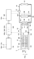
- the device temperature control device 1 includes a fluid circulation circuit 10 in which a refrigerant, which is a working fluid, circulates, and a device control device 100.
- the arrow DRg shown in FIG. 1 indicates the direction in which the vertical line extends, that is, the direction of gravity.
- fluorocarbon refrigerants for example, R134a and R1234yf
- fluorocarbon refrigerants used in a vapor compression refrigeration cycle
- working fluid not only fluorocarbon-based refrigerants, but also other refrigerants such as carbon dioxide, antifreeze, etc. can be used.
- the fluid circulation circuit 10 is a heat pipe that transfers heat by evaporation and condensation of the refrigerant, and is a loop-type thermosyphon in which a flow path through which the gaseous refrigerant flows and a flow path through which the liquid refrigerant flows are separated. Is configured.
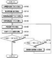
- the fluid circulation circuit 10 is configured to include a device heat exchanger 12, a condenser 14, a gas side pipe 18 which constitutes a gas passage, and a liquid side pipe 16 which constitutes a liquid passage.
- the fluid circulation circuit 10 of the present embodiment is configured as a closed annular fluid circuit by connecting the device heat exchanger 12, the condenser 14, the gas side pipe 18, and the liquid side pipe 16 to one another. There is.
- the fluid circulation circuit 10 is filled with a predetermined amount of refrigerant in a state where the inside of the fluid circulation circuit 10 is evacuated.
- FIG. 1 an example of the liquid level of the refrigerant in the heat exchanger 12 for the device at the time of cooling of the assembled battery BP is indicated by a dashed dotted line FL.
- the device heat exchanger 12 is a heat exchanger that functions as a heat absorbing portion that absorbs heat from the assembled battery BP and evaporates a liquid refrigerant when the assembled battery BP that is the target device is cooled.
- the heat exchanger 12 for apparatus has a heat exchange part 123 which makes the cylindrical upper tank 121, the cylindrical lower tank 122, the upper tank 121, and the lower tank 122 communicate.
- the upper tank 121, the lower tank 122, and the heat exchange unit 123 are made of, for example, a metal material having high thermal conductivity, such as aluminum or copper.
- the upper tank 121, the lower tank 122, and the heat exchange part 123 may be comprised with the material with high heat conductivity other than a metal material.
- the upper tank 121 is provided on the upper side of the device heat exchanger 12 in the gravity direction DRg. Further, the lower tank 122 is provided at a position below the upper tank 121 in the device heat exchanger 12 on the lower side in the gravity direction DRg.
- the heat exchange unit 123 is sandwiched between the upper tank 121 and the lower tank 122 in the gravity direction DRg. At least one refrigerant passage for flowing the refrigerant in the vertical direction is formed inside the heat exchange unit 123.
- the assembled battery BP is disposed outside the heat exchange portion 123 via a heat conductive sheet having electrical insulation (not shown).
- the heat conductive sheet is provided to ensure the insulation between the heat exchange portion 123 and the battery pack BP and to suppress the thermal resistance between the heat exchange portion 123 and the battery pack BP.
- the surface opposite to the surface on which the terminals CT of the battery cell BC are provided is installed in the heat exchange unit 123 via the heat conduction sheet.
- Each battery cell BC which comprises the assembled battery BP is arranged in the direction which cross
- the device heat exchanger 12 is provided with an upper connection 125 and a lower connection 126.
- Each of the upper side connection portion 125 and the lower side connection portion 126 is a pipe connection portion for causing the refrigerant to flow into the device heat exchanger 12 or causing the refrigerant to flow out of the device heat exchanger 12.
- the upper side connection part 125 is provided in the site
- the lower side connection part 126 is provided in the site
- the lower connection portion 126 is provided on one end side of the lower tank 122.
- the liquid side pipe 16 is connected to the lower connection portion 126.
- the condenser 14 is a heat exchanger that functions as a heat radiating portion that causes the gaseous refrigerant evaporated in the device heat exchanger 12 to be condensed by radiating heat when the battery pack BP which is the target device is cooled. is there.
- the condenser 14 is constituted by a refrigerant-refrigerant heat exchanger that cools the refrigerant flowing therein by heat exchange with the low pressure refrigerant flowing in the refrigeration cycle apparatus 50 for air conditioning the vehicle interior. .
- the condenser 14 has a gas inlet portion 141 to which the upper end of the gas side pipe 18 is connected, and a liquid outlet portion 142 to which the upper end of the liquid side pipe 16 is connected.
- the condenser 14 of this embodiment is configured such that the gas inlet portion 141 is located above the liquid outlet portion 142 in the gravity direction DRg.
- the condenser 14 is made of a metal or alloy excellent in thermal conductivity, such as aluminum or copper.
- the condenser 14 may be comprised including materials other than a metal, it is desirable to comprise at least the site
- the condenser 14 of the present embodiment is disposed at a position overlapping the heat exchange portion 123 of the heat exchanger 12 for the device in the direction orthogonal to the gravity direction DRg.
- the condenser 14 is configured such that at least the position of the gas inlet portion 141 is higher than the liquid level position of the refrigerant formed inside the condenser 14 so that the refrigerant can be condensed inside. It is assumed that
- the refrigeration cycle apparatus 50 includes a compressor 51 that compresses and discharges a refrigerant, a radiator 52 that dissipates the refrigerant discharged from the compressor 51, an air conditioning side open / close valve 53, an air conditioning side expansion valve 54, an air conditioning side evaporation And a battery-side expansion valve 57, and a battery-side evaporator 58.
- the air conditioning side evaporator 55 is a heat exchanger for cooling the air blown into the vehicle compartment.
- the air conditioning expansion valve 54 is a decompression device that decompresses and expands the refrigerant flowing into the air conditioning evaporator 55.
- the battery-side evaporator 58 is a heat exchanger for cooling the refrigerant flowing through the condenser 14.
- the battery side expansion valve 57 is a decompression device that decompresses and expands the refrigerant flowing into the battery side evaporator 58.
- the refrigerant flow downstream side of the radiator 52 is branched into the air conditioning side piping 500 and the battery side piping 510.
- the air conditioning side opening / closing valve 53, the air conditioning side expansion valve 54, and the air conditioning side evaporator 55 are disposed with respect to the air conditioning side piping 500, and the battery side opening / closing valve 56 with respect to the battery side piping 510
- An expansion valve 57 and a battery-side evaporator 58 are disposed.
- the air conditioning side on-off valve 53 and the battery side on-off valve 56 function as a flow path switching valve that switches the flow path of the refrigerant in the refrigeration cycle apparatus 50.
- the air conditioning side on-off valve 53 and the battery side on-off valve 56 are configured so that the refrigerant flows to both the air conditioning side evaporator 55 and the battery side evaporator 58. It is controlled to be open.
- the air conditioning side on-off valve 53 is controlled to be open and the battery side on-off valve 56 is controlled to be closed so that the refrigerant flows only to the air conditioning side evaporator 55.
- the air conditioning side on-off valve 53 is controlled to be closed and the battery side on-off valve 56 is controlled to be open so that the refrigerant flows only to the battery side evaporator 58.
- the gas side pipe 18 is a gas passage portion which guides the refrigerant of the gas evaporated in the heat exchanger 12 for the device to the condenser 14.
- One end of the gas-side pipe 18 is connected to the upper connection 125 of the heat exchanger 12 for an apparatus, and the other end is connected to the gas inlet 141 of the condenser 14.
- the gas side piping 18 shown in FIG. 1 is an example to the last, and can be suitably changed in consideration of the mounting property to a vehicle.
- the liquid side pipe 16 is a liquid passage portion for leading the liquid refrigerant condensed in the condenser 14 to the heat exchanger 12 for the device.
- One end of the liquid side pipe 16 is connected to the lower connection portion 126 of the heat exchanger 12 for the device, and the other end is connected to the liquid outlet portion 142 of the condenser 14.
- the liquid side piping 16 shown in FIG. 1 is an example to the last, and can be suitably changed in consideration of the mounting property to a vehicle.
- the liquid side pipe 16 is provided with a refrigerant temperature sensor 162 for detecting the temperature of the liquid refrigerant flowing inside.
- the refrigerant temperature sensor 162 is provided in a portion of the liquid side pipe 16 closer to the heat exchanger 12 for the device than the condenser 14.
- the refrigerant temperature sensor 162 can detect the temperature of the refrigerant flowing through a portion of the liquid side pipe 16 closer to the lower connection portion 126 of the heat exchanger 12 for the device than the liquid outlet portion 142 of the condenser 14
- the heat exchanger 12 is provided closer to the heat exchanger 12 than the condenser 14 is.
- the refrigerant temperature sensor 162 of this embodiment is configured to directly detect the temperature of the refrigerant flowing through the liquid side pipe 16.
- the refrigerant temperature sensor 162 may be configured to indirectly detect, for example, the temperature of the refrigerant flowing through the liquid side pipe 16 from the surface temperature of the liquid side pipe 16.
- thermosyphon system temperature controller 1 configured as described above, when the temperature of the refrigerant present on the condenser 14 side becomes lower than the battery temperature TB of the assembled battery BP, the liquid refrigerant in the heat exchanger 12 for the device Starts to evaporate. At this time, the battery pack BP is cooled by the latent heat of vaporization of the liquid working fluid in the heat exchanger 12 for equipment.
- the refrigerant evaporated inside the device heat exchanger 12 is gasified and flows into the condenser 14 through the gas side pipe 18.
- the gaseous refrigerant that has flowed into the condenser 14 is cooled by the condenser 14 to be liquefied, and flows into the heat exchanger 12 for equipment again via the liquid side pipe 16.
- the device temperature control device 1 is configured such that continuous cooling of the battery pack BP can be performed by natural circulation of the refrigerant without requiring a driving device such as a compressor.
- the liquid level in the condenser 14 becomes larger than the liquid level in the heat exchanger 12 for the device.
- the device control apparatus 100 which is an electronic control unit of the device temperature control device 1 will be described.
- the device control apparatus 100 includes a processor, a microcomputer including a storage unit 100a, and peripheral circuits thereof.
- the device control apparatus 100 performs various operations and processes based on the control program stored in the storage unit 100a.
- the storage unit 100 a of the device control apparatus 100 is configured of a non-transitional substantial storage medium.
- the refrigerant temperature sensor 162 described above is connected to the input side of the device control apparatus 100.
- the device control apparatus 100 can acquire the detection value detected by the refrigerant temperature sensor 162 as the state amount of the refrigerant.
- the refrigerant temperature sensor 162 configures a state quantity detection unit that detects the state quantity of the refrigerant that is the working fluid.
- the device control apparatus 100 is bi-directionally communicably connected to a battery control apparatus 110 for controlling the battery pack BP and an air conditioning control apparatus 120 for controlling the refrigeration cycle apparatus 50.
- the battery control device 110 is a device for controlling the input / output of the battery pack BP and monitoring the battery temperature TB and the like of the battery pack BP.
- the battery control device 110 includes a processor, a microcomputer including a storage unit, and peripheral circuits thereof. Connected to the input side of the battery control device 110 are a current sensor 110a that detects an output current value of the assembled battery BP, a battery temperature sensor 110b that detects a battery temperature TB that is an internal temperature of the assembled battery BP, and the like.
- the air conditioning control device 120 is a device for controlling the compressor 51, the air conditioning side on-off valve 53, and the battery side on-off valve 56 of the refrigeration cycle device 50.
- the air conditioning control device 120 is connected to an input side of the air conditioning control device 120, such as an outside air temperature sensor 120a that detects the outside air temperature Tam.
- the device control apparatus 100 can acquire detection values of various sensors connected to the battery control apparatus 110 by outputting a predetermined control signal to the battery control apparatus 110. Further, the device control apparatus 100 outputs various control signals to the air conditioning control apparatus 120 to control various components of the refrigeration cycle apparatus 50 or detect various sensors connected to the refrigeration cycle apparatus 50. It is possible to get a value.
- the device control apparatus 100 is configured to detect the heat generation amount Q of the battery pack BP based on detection values of various sensors acquired from the battery control apparatus 110 and the like.
- the configuration for detecting the heat generation amount Q of the battery pack BP in the device control device 100 constitutes the heat generation amount detection unit 100b.
- the device control apparatus 100 controls various constituent devices of the refrigeration cycle apparatus 50 via the air conditioning control device 120 based on detection values of various sensors acquired from the refrigerant temperature sensor 162 and the battery control device 110, and the like.
- the heat dissipation capacity of the condenser 14 can be adjusted.
- the configuration for adjusting the heat release capacity of the condenser 14 in the device control apparatus 100 constitutes the heat release capacity adjustment unit 100 c.
- control processing executed when the device control apparatus 100 of the present embodiment cools the battery pack BP will be described with reference to the flowchart shown in FIG.
- the control process shown in FIG. 2 is executed by the device control apparatus 100 at a predetermined cycle when the start switch of the vehicle is turned on.
- the device temperature control apparatus 1 may be configured to be executed when the control process shown in FIG. 2 is performed while the start switch of the vehicle is turned off.
- Each step of the control process shown in FIG. 2 constitutes a function implementing unit for realizing various functions executed by the device control apparatus 100.
- the device control apparatus 100 first sets a target battery temperature TB0 in step S100.
- the target battery temperature TB0 is a temperature at which the input / output characteristics of the battery pack BP are expected to be optimal, and is predetermined.
- the target battery temperature TB0 may not be a fixed value but a variable value that changes according to an external factor, for example, when the input / output characteristics of the battery pack BP change due to an external factor or the like.
- the device control apparatus 100 detects a battery calorific value QB which is a calorific value of the assembled battery BP. Specifically, the device control apparatus 100 acquires the output current value I of the battery pack BP from the battery control device 110, and based on the output current value I and the electric resistance value Re inside the battery pack BP, the battery heat generation amount QB. Calculate When the battery control device 110 is configured to be able to detect the battery heat generation amount QB, the device control device 100 may be configured to acquire the battery heat generation amount QB via the battery control device 110. .
- step S120 the device control apparatus 100 calculates a target contact surface temperature TS0 that is a target temperature of the battery contact surface 13 of the device heat exchanger 12 in contact with the battery pack BP, and in step S130.
- the target refrigerant temperature TR0 which is the target temperature of the liquid refrigerant, is calculated.
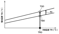
- FIG. 3 shows the relationship between the battery heat generation amount Q, the contact surface temperature TS, and the required refrigerant temperatures TR1 to TR4 evaluated by the present inventors.
- the target contact surface temperature TSO needs to be reduced as the battery heat generation amount Q increases. This is because the temperature difference due to the thermal resistance Rt inside the battery pack BP increases as the battery heat generation amount Q increases.
- the target contact surface temperature TSO is determined to be a low temperature as the battery heating value Q increases.
- the device control apparatus 100 calculates a target refrigerant temperature TR0 of the refrigerant based on the target contact surface temperature TS0.
- the target contact surface temperature TS0 is calculated based on the battery heat generation amount Q. Therefore, the device control apparatus 100 can also be interpreted as calculating the target refrigerant temperature TR0 based on the battery heat generation amount Q which is the device heat generation amount.
- the device control apparatus 100 of the present embodiment stores the relationship shown in FIG. 3 in advance as a control map in the storage unit 100a, and refers to the control map to determine the target coolant temperature from the target contact surface temperature TS0. Determine TR0. For example, when the target contact surface temperature TS0 is reached, the device control apparatus 100 determines a refrigerant temperature R2 that intersects a plot indicating TS0 among the refrigerant temperatures TR1 to TR4 shown in FIG. 3 as the target refrigerant temperature TR0.
- step S140 the device control apparatus 100 detects the refrigerant temperature TR, which is the temperature of the liquid refrigerant, with the refrigerant temperature sensor 162. Then, in step S150, the device control apparatus 100 operates the refrigeration cycle apparatus 50 such that the refrigerant temperature TR approaches the target refrigerant temperature TR0. Specifically, the device control apparatus 100 controls the air-conditioning control apparatus 120 so that the control signal for opening the battery side on-off valve 56, and the battery whose temperature difference between the refrigerant temperature TR and the target refrigerant temperature TR0 decreases. A control signal or the like for setting the throttle opening degree of the side expansion valve 57 is output.
- the device heat exchanger 12 part of the liquid refrigerant evaporates by absorbing heat from the battery pack BP.
- the battery pack BP is cooled by the latent heat of vaporization of the refrigerant in the heat exchanger 12 for equipment, and its temperature decreases.
- the gaseous refrigerant evaporated in the device heat exchanger 12 flows out from the upper connection portion 125 of the device heat exchanger 12 to the gas side pipe 18, and to the condenser 14 through the gas side pipe 18.
- the refrigerant flowing inside is condensed by radiating heat to the refrigerant flowing through the battery-side evaporator 58.
- the gaseous refrigerant is liquefied to increase the specific gravity of the refrigerant.
- the refrigerant liquefied inside the condenser 14 descends toward the liquid outlet 142 of the condenser 14 by its own weight.
- the liquid refrigerant condensed in the condenser 14 flows out from the liquid outlet portion 142 of the condenser 14 to the liquid side pipe 16, and moves to the heat exchanger 12 for equipment via the liquid side pipe 16. Then, in the device heat exchanger 12, the liquid refrigerant that has flowed in from the lower connection portion 126 via the liquid pipe 16 evaporates by absorbing heat from the assembled battery BP.
- the device temperature control device 1 circulates between the heat exchanger 12 for the device and the condenser 14 while the phase of the refrigerant changes to the gas state and the liquid state, Heat is transported from the heat exchanger 12 to the condenser 14 to cool the battery pack BP.
- step S160 the device control apparatus 100 determines whether the absolute value of the temperature difference between the refrigerant temperature TR and the target refrigerant temperature TR0 is equal to or less than a preset allowable value ⁇ 1.
- the allowable value ⁇ 1 is set to an allowable value at the time of cooling of the assembled battery BP by an experiment, a simulation or the like.
- the absolute value of the temperature difference between the refrigerant temperature TR and the target refrigerant temperature TR0 is equal to or less than the allowable value ⁇ 1, it is considered that cooling of the battery pack BP can be appropriately performed, and the device control apparatus 100 leaves this process.
- step S170 the device control apparatus 100 determines whether the subtraction value obtained by subtracting the refrigerant temperature TR from the target refrigerant temperature TR0 exceeds the allowable value ⁇ 1.
- the device control apparatus 100 returns to step S140 so as to bring the refrigerant temperature TR closer to the target refrigerant temperature TR0.
- step S180 when the subtraction value obtained by subtracting the refrigerant temperature TR from the target refrigerant temperature TR0 becomes equal to or less than the allowable value ⁇ 1, it is considered that the cooling capacity of the assembled battery BP is insufficient. For this reason, after increasing the heat dissipation capacity of the condenser 14 in step S180, the device control apparatus 100 returns to step S140.
- the temperature of the refrigerant flowing through the battery-side evaporator 58 may be decreased, or the flow rate of the refrigerant flowing through the battery-side evaporator 58 may be increased. Therefore, in step S180, the device control apparatus 100 outputs, to the air-conditioning control apparatus 120, for example, a control signal instructing the temperature decrease or the flow rate increase of the refrigerant flowing through the battery-side evaporator 58.
- the battery pack BP can be appropriately cooled.
- the device temperature control device 1 of the present embodiment described above has the heat dissipation capacity of the condenser 14 so that the difference between the refrigerant temperature TR, which is the temperature of the liquid refrigerant, and the target refrigerant temperature TR0 is reduced by the device control device 100. It is configured to adjust.
- the temperature adjustment device 1 since the temperature of the refrigerant is directly controlled, the temperature fluctuation of the refrigerant as compared with the configuration in which the heat dissipation capacity of the condenser 14 is adjusted so that the difference between the battery temperature TB and the target battery temperature TB0 becomes smaller. Is unlikely to be excessive. For this reason, in the device temperature adjustment device 1, it is possible to prevent the hunting of the temperature of the battery pack BP due to the temperature fluctuation of the refrigerant circulating in the fluid circulation circuit 10, and adjust the temperature of the battery pack BP appropriately. .
- the refrigerant temperature sensor 162 is provided for the liquid side pipe 16 to control the temperature of the refrigerant having a high correlation with the temperature of the battery pack BP. It becomes easy to adjust the temperature of the battery pack BP properly.
- the refrigerant flowing in a portion of the liquid side pipe 16 closer to the heat exchanger 12 for the device than the condenser 14 is the condenser 14.
- the influence on the temperature of the battery pack BP is considered to be larger than that of the refrigerant flowing near.
- the refrigerant temperature sensor 162 is provided in a portion of the liquid side pipe 16 closer to the heat exchanger 12 for the device than the condenser 14.
- the target refrigerant temperature TR0 is determined so that the heat release capacity of the condenser 14 increases as the heat generation amount Q of the battery pack BP increases. According to this, even if the calorific value of the assembled battery BP is increased or decreased, the temperature of the assembled battery BP can be appropriately adjusted.
- the upper side connection portion 125 connected to the gas side pipe 18 in the device heat exchanger 12 is lower than the lower side connection portion 126 connected to the liquid side pipe 16. It is configured to be located on the side. According to this, it is possible to suppress that the gaseous refrigerant flows to the liquid side pipe 16 side and the liquid refrigerant flows to the gas side pipe 18 when the battery assembly BP is cooled. As a result, the circulation of the refrigerant in the fluid circulation circuit 10 is less likely to be inhibited, so that the temperature of the battery pack BP can be appropriately adjusted.
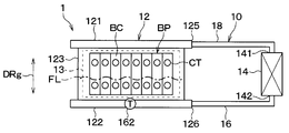
- the lower tank 122 has a liquid refrigerant rather than the gaseous refrigerant compared to the upper tank 121. Is easy to exist. For this reason, as shown in FIG. 4, for example, in the device temperature control device 1, the refrigerant temperature sensor 162 is in the lower tank 122 of the device heat exchanger 12 in which the liquid refrigerant is more likely to be present than the gaseous refrigerant. It may be provided.
- the refrigerant temperature sensor 162 may be provided at a portion of the heat exchange unit 123 closer to the lower tank 122 than the upper tank 121.
- the refrigerant temperature sensor 162 is provided in the heat exchange unit 123, there is a concern that the heat exchange between the refrigerant and the battery pack BP may be inhibited by the refrigerant temperature sensor 162.
- the device temperature control device 1 is configured such that the refrigerant temperature sensor 162 is provided in the portion 14 of the condenser 14 where the liquid refrigerant is more likely to be present than the gaseous refrigerant.
- the portion 143 of the condenser 14 where the liquid refrigerant is more likely to be present than the gaseous refrigerant is, for example, a portion closer to the liquid outlet portion 142 than the gas inlet portion 141 of the condenser 14.
- the device temperature control device 1 of this embodiment is different from the first embodiment in that the state of the refrigerant circulating in the fluid circulation circuit 10 can be notified to the outside.
- parts different from the first embodiment will be mainly described, and description of parts equivalent to the first embodiment may be omitted.
- a notification device 130 for notifying the user etc. of information is connected on the output side thereof.
- the notification device 130 includes, for example, an audio output unit for outputting information in voice and an information display unit for visually displaying information.
- FIG. 7 corresponds to FIG. 2 of the first embodiment.
- the same steps as those in FIG. 2 are denoted by the same reference numerals as those in the first embodiment.
- the device control apparatus 100 After detecting the refrigerant temperature TR in step S140, the device control apparatus 100 outputs an operation state signal indicating the refrigerant temperature TR to the notification device 130 in step S142. Thereby, the notification device 130 notifies the refrigerant temperature TR to the outside by the voice output unit and the information display unit.
- step S170 when the result of the determination processing in step S170 shows that the subtraction value obtained by subtracting the refrigerant temperature TR from the target refrigerant temperature TR exceeds the allowable value ⁇ 1, the device control apparatus 100 cools the assembled battery BP in step S172. It is determined whether a reference time has elapsed since the start. The reference time is set to be longer than the time required to set the refrigerant temperature TR at the start of cooling of the battery pack BP to the target refrigerant temperature TR0. The necessary time may be calculated by experiment or simulation.
- step S172 when the reference time has not elapsed from the start of cooling of the battery pack BP, it is considered that it is a transition period of cooling of the battery pack BP. Therefore, the device control apparatus 100 proceeds to step S180.
- step S190 the device control apparatus 100 outputs an operation failure signal indicating the operation failure state of the device temperature adjustment device 1 to the notification device 130.
- the notification device 130 notifies the malfunction state of the device temperature control device 1 to the outside by the voice output unit and the information display unit.
- the device temperature control device 1 of the present embodiment can obtain the same effects and advantages as those of the first embodiment from the common configuration and operation of the first embodiment.
- the device control apparatus 100 since the device control apparatus 100 according to the present embodiment can notify the refrigerant temperature TR and the like in the device temperature control device 1 to the outside through the notification device 130, the operating state of the device temperature control device 1, the assembled battery, There is an advantage that it becomes easy to grasp the temperature condition etc. of BP.
- the device control apparatus 100 since the device control apparatus 100 according to the present embodiment can notify the malfunction state of the device temperature control device 1 to the outside through the notification device 130, the user can check or repair the device temperature control device 1. It has the advantage of being able to encourage.
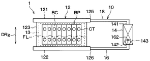
- the device temperature control apparatus 1 of the present embodiment is different from the first embodiment in that a plurality of condensers 14A and 14B are provided.
- parts different from the first embodiment will be mainly described, and description of parts equivalent to the first embodiment may be omitted.
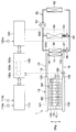
- the device temperature control apparatus 1 includes a first condenser 14A and a second condenser 14B.
- the first condenser 14A and the second condenser 14B are connected to the gas side pipe 18 and the liquid side pipe 16 so as to be in parallel in the fluid circulation circuit 10.
- portions on the side of the first condenser 14A and the second condenser 14B are able to supply the gaseous refrigerant to both the first condenser 14A and the second condenser 14B. Bifurcated.
- liquid side pipe 16 of the present embodiment is a portion on the side of the first condenser 14A and the second condenser 14B so that the liquid refrigerant can be drawn out from both the first condenser 14A and the second condenser 14B. Are bifurcated.
- the first condenser 14A is a low-pressure refrigerant flowing in the refrigeration cycle apparatus 50 for air conditioning the passenger compartment, in the refrigerant flowing therein. And a refrigerant-refrigerant heat exchanger which is cooled by heat exchange.
- the second condenser 14B is an air-cooled heat exchanger which condenses the gaseous working fluid by exchanging heat between the blast air blown from the blower fan BF and the gaseous working fluid. It is done.
- the blower fan BF is a device that blows out air outside the vehicle toward the second condenser 14B.
- the blower fan BF is composed of an electric fan operated by energization.
- the blower fan BF is connected to the air conditioning control device 120.
- the device control apparatus 100 can control the air blowing capacity of the air blowing fan BF by outputting a control signal to the air conditioning control apparatus 120.
- the power and power required to operate the blower fan BF are smaller than the power and power required to operate the refrigeration cycle apparatus 50.
- the outside air temperature Tam is lower than the refrigerant temperature TR. That is, the heat dissipation capacity of the refrigerant by the operation of the blower fan BF is smaller than the heat dissipation capacity of the refrigerant by the refrigeration cycle apparatus 50.
- the device control apparatus 100 is configured to be able to separately adjust the heat dissipation capacity of the first condenser 14A and the heat dissipation capacity of the second condenser 14B. That is, the device control apparatus 100 is configured to be able to adjust the heat release capacity of some of the plurality of condensers 14A and 14B separately from the heat release capacity of the other condensers. Then, the device control apparatus 100 is configured to select one of the first condenser 14A and the second condenser 14B based on the target refrigerant temperature TR0, and adjust the heat radiation capacity of the selected condenser.
- FIG. 10 corresponds to FIG. 2 of the first embodiment.
- the same steps as those in FIG. 2 are denoted by the same reference numerals as in the first embodiment.
- step S140 after detecting the refrigerant temperature TR in step S140, the device control apparatus 100 proceeds to step S160, and the absolute value of the temperature difference between the refrigerant temperature TR and the target refrigerant temperature TR0 is set in advance. It is determined whether it is less than or equal to the allowable value ⁇ 1.
- the device control apparatus 100 determines that the target refrigerant temperature TR0 is the outside air temperature in step S200. It is determined whether it is smaller than Tam.
- step S210 the device control apparatus 100 operates the refrigeration cycle apparatus 50 such that the refrigerant temperature TR approaches the target refrigerant temperature TR0 while stopping the blower fan BF. Specifically, the device control apparatus 100 controls the air-conditioning control apparatus 120 so that the control signal for opening the battery side on-off valve 56, and the battery whose temperature difference between the refrigerant temperature TR and the target refrigerant temperature TR0 decreases. A control signal or the like for setting the throttle opening degree of the side expansion valve 57 is output.
- step S220 the device control apparatus 100 increases the heat dissipation capacity of the first condenser 14A, and then returns to step S140.
- the refrigerant circulates between the device heat exchanger 12 and the first condenser 14A while being phase-changed into the gas state and the liquid state, and the device heat exchanger 12
- the assembled battery BP is cooled by transporting the heat to the one condenser 14A.
- the ventilation fan BF is stopping, compared with the case where the refrigerating cycle apparatus 50 and the ventilation fan BF are operated, the assembled battery BP can be cooled by power saving and power saving.
- step S230 the device control apparatus 100 operates the blower fan BF so that the refrigerant temperature TR approaches the target refrigerant temperature TR0 while the refrigeration cycle apparatus 50 is stopped. Specifically, the device control apparatus 100 outputs, to the air conditioning control apparatus 120, a control signal for instructing the operation of the blower fan BF, and the like.
- the device control apparatus 100 returns to step S140.
- the refrigerant circulates between the device heat exchanger 12 and the second condenser 14B while changing its phase to the gas state and the liquid state, and the device heat exchanger 12
- the heat is transported to the second condenser 14B, whereby the battery pack BP is cooled.
- the battery assembly BP can be cooled with power saving and power saving as compared with the case where the refrigeration cycle apparatus 50 and the blower fan BF are operated.
- the device temperature control device 1 of the present embodiment can obtain the same effects and advantages as those of the first embodiment from the common configuration and operation of the first embodiment.
- the device control apparatus 100 of the present embodiment is configured to be able to individually adjust the heat radiation capabilities of the first condenser 14A and the second condenser 14B provided in the fluid circulation circuit 10. According to this, it is possible to expand the adjustment range of the heat dissipation capacity of the working fluid as the whole of the device temperature control device 1 at the time of cooling of the assembled battery BP. According to this, even if the temperature of the battery pack BP fluctuates significantly, it is possible to appropriately adjust the temperature of the battery pack BP according to the temperature fluctuation.
- the device control apparatus 100 of the present embodiment selects one of the first condenser 14A and the second condenser 14B based on the relationship between the target refrigerant temperature TR0 and the outside air temperature Tam, and the heat radiation capacity of the selected condenser It is configured to adjust the According to this, even if the temperature of the battery pack BP fluctuates significantly, the device temperature control device 1 capable of appropriately adjusting the temperature of the battery pack BP in response to the temperature fluctuation can be specifically realized.
- the above-mentioned 3rd Embodiment demonstrated the example which thermally radiates the refrigerant
- the first condenser 14A and the second condenser 14B may be configured to dissipate the refrigerant in the fluid circulation circuit 10 by the same type of fluid.
- the first condenser 14A and the second condenser 14B may be configured to dissipate the refrigerant in the fluid circulation circuit 10 by the low-pressure refrigerant of the separate refrigeration cycle apparatus 50.
- the capacities of the compressors of the respective refrigeration cycle apparatuses 50 and the sizes and capacities of the heat exchangers may be different. The same applies to the following fourth embodiment.
- the device control apparatus 100 is configured to change the adjustment order of the heat dissipation capabilities of the first condenser 14A and the second condenser 14B based on the refrigerant temperature TR and the target refrigerant temperature TR0. It is different from the third embodiment. In the present embodiment, portions different from the third embodiment will be mainly described, and description of portions equivalent to the third embodiment may be omitted.
- FIG. 11 corresponds to FIG. 10 of the third embodiment.
- the same steps as those in FIG. 10 are denoted by the same reference numerals as in the first embodiment.
- step S222 the device control apparatus 100 determines whether the absolute value of the temperature difference between the refrigerant temperature TR and the target refrigerant temperature TR0 is less than or equal to a preset reference value ⁇ 2.
- the reference value ⁇ 2 is a determination threshold value for determining whether the refrigerant temperature TR and the target refrigerant temperature TR0 largely deviate, and is set to a value larger than the allowable value ⁇ 1.
- the device control apparatus 100 causes the blower fan BF to make the refrigerant temperature TR approach the target refrigerant temperature TR0 early.
- the refrigeration cycle apparatus 50 is operated in a state in which is stopped. That is, when the absolute value of the temperature difference between the refrigerant temperature TR and the target refrigerant temperature TR0 is larger than the reference value ⁇ 2, the device control apparatus 100 proceeds to step S210.
- the device control apparatus 100 proceeds to step S230 and operates the blower fan BF.
- the other configuration and operation are similar to those of the third embodiment.
- the device temperature control apparatus 1 of the present embodiment can obtain the same effects and advantages as those of the third embodiment from the common configuration and operation of the third embodiment.
- the device control apparatus 100 changes the adjustment order of the heat dissipation capabilities of the first condenser 14A and the second condenser 14B based on the relationship between the refrigerant temperature TR and the target refrigerant temperature TR0. It has become. Specifically, when there is a difference in the heat release capacities of the plurality of condensers 14A and 14B, the device control apparatus 100 has a high heat release capacity when the difference between the refrigerant temperature TR and the target refrigerant temperature TR0 is large. The heat is dissipated by the refrigerant 14A. According to this, it is possible to rapidly reduce the difference between the refrigerant temperature TR and the target refrigerant temperature TR0.
- the present embodiment is different from the first embodiment in that the configuration is such that the temperature of the gaseous refrigerant, not the temperature of the liquid refrigerant, is detected as the state quantity of the refrigerant.
- parts different from the first embodiment will be mainly described, and description of parts equivalent to the first embodiment may be omitted.
- the refrigerant undergoes a phase change from a liquid state to a gas state.
- the temperature of the gaseous refrigerant becomes substantially equal to the temperature of the liquid refrigerant. Therefore, there is almost no temperature difference between the liquid refrigerant and the gaseous refrigerant in the vicinity of the heat exchanger 12 for the device.
- the refrigerant temperature sensor 162 for detecting the temperature of the liquid refrigerant is eliminated, and the gaseous refrigerant flowing inside with respect to the gas side pipe 18
- a refrigerant temperature sensor 182 is provided to detect the temperature of The refrigerant temperature sensor 182 is provided in a portion of the gas side pipe 18 closer to the heat exchanger 12 for the device than the condenser 14.
- the refrigerant temperature sensor 182 can detect the temperature of the refrigerant flowing through a portion of the gas side pipe 18 closer to the upper connection portion 125 of the heat exchanger 12 for the device than the gas inlet portion 141 of the condenser 14 As such, the heat exchanger 12 is provided closer to the heat exchanger 12 than the condenser 14 is.
- the refrigerant temperature sensor 182 of the present embodiment is configured to directly detect the temperature of the refrigerant flowing through the gas side pipe 18.
- the refrigerant temperature sensor 182 may be configured to indirectly detect, for example, the temperature of the refrigerant flowing through the gas side pipe 18 from the surface temperature of the gas side pipe 18.
- the refrigerant temperature sensor 182 described above is connected to the input side of the device control apparatus 100.
- the refrigerant temperature sensor 182 constitutes a state quantity detection unit that detects the state quantity of the refrigerant that is the working fluid. Accordingly, the device control apparatus 100 according to the present embodiment detects the refrigerant temperature TR by the refrigerant temperature sensor 182, for example, in step S140 of FIG.
- the temperature when the gaseous refrigerant flowing through the fluid circulation circuit 10 is heated by the heat generation of the battery pack BP, the temperature may be higher than that of the liquid refrigerant. Therefore, when using the refrigerant temperature sensor 182, it is desirable to correct the sensor output in accordance with the calorific value of the assembled battery BP. Specifically, the correction amount to be added to the sensor output of the refrigerant temperature sensor 182 may be increased as the heat generation amount of the battery pack BP increases.
- the device temperature control apparatus 1 of this embodiment is configured to detect the refrigerant temperature TR by the refrigerant temperature sensor 182, but the operation and effects exhibited from the configuration and operation of the first embodiment are the same as those of the first embodiment It can be obtained similarly.
- the gaseous refrigerant evaporated in the heat exchange section 123 flows into the upper tank 121, so the upper tank 121 side is more gaseous than the liquid refrigerant compared to the lower tank 122 side.
- the refrigerant is likely to be present.
- the refrigerant temperature sensor 182 is used in the upper tank 121 of the device heat exchanger 12 in which gaseous refrigerant tends to be present more easily than liquid refrigerant. It may be provided.
- the refrigerant temperature sensor 182 may be provided at a portion of the heat exchange unit 123 closer to the upper tank 121 than the lower tank 122.
- the refrigerant temperature sensor 182 is provided in the heat exchange unit 123, there is a concern that the heat exchange between the refrigerant and the battery pack BP may be inhibited by the refrigerant temperature sensor 182.
- the device temperature control device 1 is configured such that the refrigerant temperature sensor 182 is provided in the portion 14 of the condenser 14 where the gaseous refrigerant tends to be present more than the liquid refrigerant.
- the portion 144 of the condenser 14 in which the gaseous refrigerant is more likely to be present than the liquid refrigerant is, for example, a portion closer to the gas inlet portion 141 than the liquid outlet portion 142 of the condenser 14.
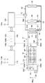
- the present embodiment is different from the first embodiment in that the pressure of the liquid refrigerant, not the temperature of the liquid refrigerant, is detected as the state quantity of the refrigerant.
- parts different from the first embodiment will be mainly described, and description of parts equivalent to the first embodiment may be omitted.
- the temperature and pressure of the refrigerant circulating in the fluid circulation circuit 10 have a relationship in which the pressure of the refrigerant increases as the temperature of the refrigerant rises, and the pressure of the refrigerant decreases as the temperature of the refrigerant decreases.
- the device temperature adjustment device 1 of the present embodiment is a refrigerant pressure sensor that detects the pressure of the gaseous refrigerant flowing inside, instead of the refrigerant temperature sensor 162 with respect to the liquid side pipe 16 164 are provided.
- the refrigerant pressure sensor 164 is provided at a portion of the liquid side pipe 16 closer to the heat exchanger 12 for the device than the condenser 14.
- the refrigerant pressure sensor 164 can detect the pressure of the refrigerant flowing through a portion of the gas side pipe 18 closer to the upper connection portion 125 of the heat exchanger 12 for the device than the gas inlet portion 141 of the condenser 14 As such, the heat exchanger 12 is provided closer to the heat exchanger 12 than the condenser 14 is.
- the refrigerant pressure sensor 184 of this embodiment is configured to directly detect the pressure of the refrigerant flowing through the liquid side pipe 16.
- the refrigerant pressure sensor 164 described above is connected to the input side of the device control apparatus 100.
- the refrigerant pressure sensor 164 constitutes a state quantity detection unit that detects the state quantity of the refrigerant that is the working fluid.
- FIG. 16 corresponds to FIG. 2 of the first embodiment.
- the same steps as those in FIG. 2 are denoted by the same reference numerals as in the first embodiment.
- the device control apparatus 100 calculates a target refrigerant pressure PR0 in step S130A. For example, the device control apparatus 100 calculates the target refrigerant temperature TR0 of the refrigerant based on the target contact surface temperature TS0, and calculates the refrigerant pressure corresponding to the calculated target refrigerant temperature TR0 as the target refrigerant pressure PR0.
- the target refrigerant pressure PR0 is calculated from the target refrigerant temperature TR0
- a control map that defines the correspondence between the refrigerant temperature TR and the refrigerant pressure PR may be referred to. Since the target contact surface temperature TS0 is calculated based on the battery heat generation amount Q, the device control apparatus 100 is interpreted as calculating the target refrigerant pressure PR0 based on the battery heat generation amount Q, which is the device heat generation amount. You can also
- step S140A the device control apparatus 100 detects the refrigerant pressure PR, which is the pressure of the liquid refrigerant, with the refrigerant pressure sensor 164. Then, in step S150, the device control apparatus 100 operates the refrigeration cycle apparatus 50 such that the refrigerant pressure PR approaches the target refrigerant pressure PR0.
- the refrigerant pressure PR which is the pressure of the liquid refrigerant
- step S160A device control apparatus 100 performs, in step S160A, the absolute value of the pressure difference between refrigerant pressure PR and target refrigerant pressure PR0 at preset allowance value ⁇ 3. It is determined whether or not The allowable value ⁇ 3 is set to an allowable value at the time of cooling of the battery pack BP by an experiment, a simulation, or the like.
- the absolute value of the pressure difference between the refrigerant pressure PR and the target refrigerant pressure PR0 is equal to or less than the allowable value ⁇ 3, it is considered that cooling of the battery pack BP can be appropriately performed, and the device control apparatus 100 leaves this process.
- step S170A the device control apparatus 100 determines whether the subtraction value obtained by subtracting the refrigerant pressure PR from the target refrigerant pressure PR0 exceeds the allowable value ⁇ 3.
- the device control apparatus 100 returns to step S140 in order to bring the refrigerant pressure PR closer to the target refrigerant pressure PR0.
- step S180 when the subtraction value obtained by subtracting the refrigerant pressure PR from the target refrigerant pressure PR0 becomes equal to or less than the allowable value ⁇ 3, it is considered that the cooling capacity of the assembled battery BP is insufficient. For this reason, after increasing the heat dissipation capacity of the condenser 14 in step S180, the device control apparatus 100 returns to step S140.
- the device temperature control device 1 of this embodiment is configured to control the pressure of the refrigerant having a high correlation with the temperature of the battery pack BP, the operation and effects exhibited from the configuration and operation of the first embodiment It can be obtained similarly to the one embodiment.
- the device temperature control device 1 is provided with a refrigerant pressure sensor 184 that detects the pressure of the refrigerant with respect to the gas side pipe 18, and detects the pressure of the refrigerant flowing through the gas side pipe 18. It may be done. Further, the refrigerant pressure sensors 164 and 184 may be provided inside the heat exchanger 12 for an apparatus or in the condenser 14 as in each modification of the first embodiment or each modification of the fifth embodiment. .
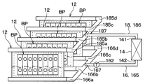
- the device temperature control device 1 of this embodiment is different from the first embodiment in that a plurality of device heat exchangers 12 are provided in order to cool a plurality of battery packs BP.
- a plurality of device heat exchangers 12 are provided in order to cool a plurality of battery packs BP.
- parts different from the first embodiment will be mainly described, and description of parts equivalent to the first embodiment may be omitted.
- the device temperature control apparatus 1 includes four device heat exchangers 12.
- the four apparatus heat exchangers 12 are connected to the gas side pipe 18 and the liquid side pipe 16 so as to be in parallel in the fluid circulation circuit 10.
- the gas side pipe 18 of the present embodiment combines four upstream gas passages 185a to 185d, a single downstream gas passage 186, and four upstream gas passages 185a to 185d into the downstream gas passage 186.
- a merging portion 187 is provided.
- the four upstream gas passages 185a to 185d are connected to the upper connection 125 of the heat exchanger 12 for the apparatus.
- the downstream gas passage 186 is connected to the gas inlet portion 141 of the condenser 14.
- the liquid side pipe 16 of the present embodiment includes a single upstream side fluid passage 165, four downstream side fluid passages 166a to 166d, and a single upstream side fluid passage 165 as four downstream side fluid passages 166a to 166d.
- Branch portion 167 for branching into two.
- the single upstream fluid passage 165 is connected to the fluid outlet portion 142 of the condenser 14.
- the four downstream fluid passages 166a to 166d are connected to the lower connection portion 126 of the heat exchanger 12 for the device.
- a refrigerant temperature sensor 162 is provided in the liquid side pipe 16 at a portion closer to the branch portion 167 than the liquid outlet portion 142 of the condenser 14 in the upstream side liquid passage 165.
- the other configuration is the same as that of the first embodiment. Since the device temperature control device 1 of the present embodiment is configured to detect the temperature of the refrigerant having a high correlation with the temperature of the battery pack BP, the effects and advantages exhibited from the configuration and operation of the first embodiment It can be obtained similarly to the one embodiment.
- the refrigerant temperature sensor 162 may be provided in each of the four downstream fluid passages 166a to 166d. In this case, it is desirable to provide the refrigerant temperature sensor 162 at a portion closer to the lower connection portion 126 of the heat exchanger 12 than the branch portion 167 among the four downstream side liquid passages 166a to 166d.
- each refrigerant temperature sensor 162 may be used as the refrigerant temperature TR. Just do it.
- the refrigerant temperature sensor 162 may be provided in a part of the four downstream side fluid passages 166a to 166d when the necessity for providing the refrigerant temperature sensor 162 in each of the four downstream side fluid passages 166a to 166d is low.
- the device temperature adjustment device 1 is provided with a refrigerant temperature sensor 182 at a location closer to the junction portion 187 of the downstream gas passage 186 than the gas inlet portion 141 of the condenser 14, and It may be configured to detect the temperature of the flowing refrigerant.
- the device temperature adjustment device 1 has a configuration in which the refrigerant temperature sensor 182 is provided in each of the four upstream gas passages 185 a to 185 d to detect the temperature of the refrigerant flowing through the gas side pipe 18. May be In this case, it is desirable to provide the refrigerant temperature sensor 182 at a location closer to the upper connection 125 of the heat exchanger 12 than the junction 187 among the four upstream gas passages 185a to 185d.
- each refrigerant temperature sensor 182 may be used as the refrigerant temperature TR. Just do it.
- the refrigerant temperature sensor 182 may be provided in a part of the four upstream gas passages 185a to 185d when the necessity for providing the refrigerant temperature sensor 182 on each of the four upstream gas passages 185a to 185d is low.
- an eighth embodiment will be described with reference to FIG. 22 and FIG.
- the present embodiment is different from the first embodiment in that the target refrigerant temperature TR0 is corrected in consideration of the relationship between the contact surface temperature TS and the target contact surface temperature TS0.
- parts different from the first embodiment will be mainly described, and description of parts equivalent to the first embodiment may be omitted.
- the device temperature control device 1 of the present embodiment is provided with a contact surface temperature sensor 127 that detects the contact surface temperature TS with respect to the device heat exchanger 12.
- the contact surface temperature sensor 127 described above is connected to the input side of the device control apparatus 100.
- FIG. 23 corresponds to FIG. 2 of the first embodiment.
- the steps that are the same as in FIG. 2 are given the same reference numerals as in the first embodiment.
- step S160 when the absolute value of the temperature difference between the refrigerant temperature TR and the target refrigerant temperature TR0 is equal to or smaller than the allowable value ⁇ 1 as a result of the determination processing in step S160, the device control apparatus 100 proceeds to step S250. .
- step S250 the device control apparatus 100 determines whether the absolute value of the difference between the target contact surface temperature TS0 and the current contact surface temperature TS is less than or equal to a predetermined allowable temperature difference ⁇ 0.
- the allowable temperature difference ⁇ 0 is set to an allowable value at the time of cooling of the battery pack BP by experiments, simulations, and the like.
- step S260 the device control apparatus 100 calculates a subtraction value dT obtained by subtracting the current contact surface temperature TS from the target contact surface temperature TS0.
- step S270 the device control apparatus 100 corrects the target refrigerant temperature TR0 with the above-described subtraction value dT.
- step S270 the device control apparatus 100 sets a target refrigerant temperature TR0 that is obtained by adding the subtraction value dT to the target refrigerant temperature TR0 calculated in step S130. Thereafter, the device control apparatus 100 proceeds to step S180, and increases the heat dissipation capacity of the condenser 14 such that the refrigerant temperature TR approaches the target refrigerant temperature TR0 set in step S270.
- the device temperature control device 1 of the present embodiment can obtain the same effects and advantages as those of the first embodiment from the common configuration and operation of the first embodiment.
- the heat dissipation of the condenser 14 occurs when the contact surface temperature TS does not converge to the target contact surface temperature TS0.
- the refrigeration cycle apparatus 50 is configured to be controlled to increase the capacity. According to this, since the contact surface temperature TS can be brought close to the target contact surface temperature TS0 at an early stage, the temperature of the battery pack BP can be appropriately adjusted.
- the subtraction value dT obtained by subtracting the current contact surface temperature TS from the target contact surface temperature TS0 is used as a correction value for correcting the target refrigerant temperature TR0.
- the correction value of the target refrigerant temperature TR0 may be, for example, the difference between the target battery temperature TB0 and the battery temperature TB, the difference between the surface temperature of the heat exchanger 12 for the device, and the battery temperature TB.
- the ninth embodiment A ninth embodiment will now be described with reference to FIGS. 24 to 26.
- the device temperature control device 1 of the present embodiment is different from the eighth embodiment in that the battery assembly BP can be warmed up in addition to the cooling of the battery assembly BP.
- parts different from the eighth embodiment will be mainly described, and description of parts equivalent to the eighth embodiment may be omitted.
- the device heat exchanger 12 of the present embodiment is configured to be able to exchange heat between the refrigerant and the battery assembly BP so that the refrigerant condenses when the battery assembly BP is warmed up.
- the second upper connecting portion 125B is connected to the upper tank 121 of the heat exchanger 12 of the present embodiment. Is provided.
- the second upper connection portion 125B is provided at a portion on the upper side of the device heat exchanger 12 in the gravity direction DRg, similarly to the first upper connection portion 125A.
- the lower tank 122 of the heat exchanger 12 for the apparatus of the present embodiment is provided with a second lower connection portion 126B. Similarly to the first lower connection portion 126A, the second lower connection portion 126B is provided at a portion of the heat exchanger 12 below the gravity direction DRg.
- the heat exchanger 12 for a device of the present embodiment is provided with the communication passage portion 22 which causes the second upper connection portion 125B and the second lower connection portion 126B to communicate with each other.
- the communication passage portion 22 is configured by a pipe that communicates with the second upper connection portion 125B and the second lower connection portion 126B without including the condenser 14 on the path.
- a heating device 20 for heating a liquid refrigerant flowing in the communication passage portion 22 is disposed.
- the heating device 20 is configured by an electric heater that generates heat by energization.
- the heating device 20 of the present embodiment is configured of a variable type electric heater whose calorific value changes in accordance with the amount of current. The amount of current supplied to the heating device 20 is controlled in accordance with the control signal from the device control apparatus 100.
- the communication passage portion 22 is provided with a communication side temperature sensor 222 which detects the temperature of the gaseous refrigerant flowing inside.
- the communication side temperature sensor 222 is closer to the second upper connecting portion 125 B of the heat exchanger 12 for the device than the heating device 20 so as to be less susceptible to the temperature of the heating device 20. It is provided.
- the communication-side temperature sensor 222 configures a state quantity detection unit that detects the state quantity of the refrigerant that is the working fluid.
- control processing executed when the device control apparatus 100 according to the present embodiment warms up the assembled battery BP will be described with reference to the flowchart shown in FIG.
- the control process shown in FIG. 25 is executed by the device control apparatus 100 at a predetermined cycle when the outside air temperature Tam becomes equal to or lower than a predetermined temperature (for example, zero degree).
- a predetermined temperature for example, zero degree.
- the device control apparatus 100 first sets a target battery temperature TB0 in step S500.
- the target battery temperature TB0 is a temperature at which the input / output characteristics of the battery pack BP are expected to be optimal, and is predetermined.
- the target battery temperature TB0 may not be a fixed value but a variable value that changes according to an external factor, for example, when the input / output characteristics of the battery pack BP change due to an external factor or the like.
- step S510 the device control apparatus 100 calculates a target contact surface temperature TS0 that is a target temperature of the battery contact surface 13 of the device heat exchanger 12 in contact with the battery pack BP, and in step S520.
- the target refrigerant temperature TR0 which is the target temperature of the liquid refrigerant, is set.
- the device control apparatus 100 calculates the target contact surface temperature TS0 so as to be higher than the target battery temperature TB0.
- the device control apparatus 100 sets a target refrigerant temperature TR0 of the refrigerant based on the target contact surface temperature TS0.
- the target contact surface temperature TS0 calculated in step S510 is set to the target refrigerant temperature TR0.
- step S530 the device control apparatus 100 operates the heating device 20 in a state in which the refrigeration cycle apparatus 50 is stopped. Specifically, the device control apparatus 100 controls the amount of current supplied to the heating device 20 such that the refrigerant temperature R approaches the target refrigerant temperature TR0.
- the refrigerant in the communication passage 22 vaporizes. Then, the refrigerant in the form of vapor flows upward through the communication passage portion 22 and flows into the upper tank 121 of the heat exchanger 12 for the device from the second upper connection portion 125B.
- the gaseous refrigerant that has flowed into the upper tank 121 flows through the heat exchange section 123 in contact with the low-temperature assembled battery BP, and is condensed by heat exchange with the assembled battery BP.
- the battery pack BP is warmed up (i.e., warmed) by the latent heat of condensation of the refrigerant.
- the refrigerant condensed in the heat exchange unit 123 of the device heat exchanger 12 flows toward the lower tank 122 of the device heat exchanger 12, and returns to the communication passage 22 from the second lower connection portion 126B.
- the heat of the heating device 20 is transported to the device heat exchanger 12 via the refrigerant to add the assembled battery BP. Be warmed.
- step S540 the device control apparatus 100 detects the refrigerant temperature TR, which is the temperature of the gaseous refrigerant supplied from the communication passage portion 22 to the device heat exchanger 12, with the communication-side temperature sensor 222.
- step S550 the device control apparatus 100 determines whether the absolute value of the temperature difference between the refrigerant temperature TR and the target refrigerant temperature TR0 is equal to or less than a preset allowable value ⁇ 1.
- the allowable value ⁇ 1 is set to an allowable value at the time of warming up the assembled battery BP by an experiment, a simulation, or the like.
- the device control apparatus 100 returns to step S540 and continues the operation of the heating device 20.
- the device control apparatus 100 detects the contact surface temperature TS by the contact surface temperature sensor 127 in step S560. . Then, in step S570, the device control apparatus 100 determines whether the difference between the contact surface temperature TS and the target contact surface temperature TS0 is equal to or less than a predetermined reference value ⁇ 2.
- the device control apparatus 100 returns to step S500, and performs calculation of the target contact surface temperature TS0 and setting of the target refrigerant temperature TR0 again.
- the device temperature adjustment device 1 of the present embodiment described above has a small difference between the target refrigerant temperature TR0 and the refrigerant temperature TR, which is the temperature of the gaseous refrigerant supplied to the device heat exchanger 12 by the device control apparatus 100. Thus, the capacity of the heating device 20 is adjusted.
- the capacity of the heating device 20 is adjusted so that the difference between the refrigerant temperature TR and the target refrigerant temperature TR0 becomes small, the temperature fluctuation of the refrigerant is unlikely to be excessive. Therefore, it is possible to appropriately adjust the temperature of the battery pack BP while avoiding hunting of the temperature of the battery pack BP due to the temperature change of the refrigerant.
- the apparatus temperature control apparatus 1 of this embodiment demonstrated the example in which warming up of the assembled battery BP is possible in addition to cooling of the assembled battery BP, it is not limited to this.
- the device temperature control device 1 may be configured to be able to warm up only the battery pack BP.
- the device temperature adjustment device 1 may be configured to adjust the capability of the heating device 20 so that the state quantity other than the temperature of the refrigerant that is the working fluid approaches the target state quantity.
- the device temperature adjusting device 1 may be configured to adjust the capability of the heating device 20 so that the difference between the refrigerant pressure PR and the target refrigerant pressure PR0 becomes smaller.
- each embodiment illustrated the composition which makes the condenser 14 radiate heat by the low pressure refrigerant which flows through refrigeration cycle device 50, or the open air supplied from ventilation fan BF, it is not limited to this.
- the apparatus temperature control device 1 may be configured to radiate the heat of the condenser 14 by, for example, cooling water flowing in a cooling circuit for cooling another apparatus, a Peltier element or the like which generates cold heat by energization.
- the battery calorific value QB which is the calorific value of the battery pack BP
- the device temperature adjustment device 1 may be configured to estimate the battery heat generation amount QB from at least one state of, for example, the electric energy of the assembled battery BP, the current value, the battery temperature, the environmental temperature, the heat amount, the heat capacity, etc. .
- each embodiment demonstrated the example which detects battery temperature TB of the assembled battery BP by the battery temperature sensor 110b, it is not limited to this.
- the device temperature adjustment device 1 may be configured to estimate the battery temperature TB, for example, from at least one of the current value of the assembled battery BP, the electrical resistance, the heat capacity, the calorific value, and the like. Further, the device temperature adjustment device 1 estimates the battery temperature TB from at least one of the temperature of the heat exchanger 12 for the device, the contact surface temperature between the assembled battery BP and the heat exchanger 12 for the device, and the thermal resistance. You may
- the target refrigerant temperature TR0 is described with reference to a control map in which the refrigerant temperature TR, the battery heat generation amount Q, the target contact surface temperature TS0, etc. are defined.
- the device temperature adjustment device 1 may be configured to calculate the target refrigerant temperature TR0, for example, from the electrical resistance value inside the battery pack BP, the contact surface temperature TS, the thermal resistance of the refrigerant, and the like.
- each embodiment explained the example where condenser 14 is arranged in the position which overlaps with heat exchange part 123 of heat exchanger 12 for apparatus in the direction orthogonal to gravity direction DRg, it is not limited to this .
- the condenser 14 may be disposed above the heat exchange portion 123 of the heat exchanger 12 for the device in the gravity direction DRg.
- the battery pack BP is illustrated as a target device whose device temperature control device 1 adjusts the temperature, the present invention is not limited to this.
- the target device may be, for example, another device that requires cooling or warming up, such as a motor, an inverter, or a charger.
- the device temperature controller controls the condenser to reduce the difference between the working fluid state quantity and the target state quantity.
- the heat dissipation capacity of the is adjusted.
- the device temperature control device includes a calorific value detection unit that detects a physical quantity having a correlation with the calorific value of the target device. Then, the control device determines the target state quantity so that the heat dissipation capacity of the condenser increases at least with the increase of the heat generation amount of the target device.
- the temperature of the target device does not easily decrease. Therefore, if the target state quantity is determined so that the heat release capacity of the condenser increases as the heat generation amount of the target device increases, the temperature of the target device is appropriate even if the heat generation amount of the target device increases or decreases. It is possible to adjust to
- the heat exchanger for equipment of the equipment temperature control device is provided at the upper connection portion where the working fluid flows in or out, and at the lower portion in the gravity direction than the upper connection portion A lower connection is included into which the working fluid flows in or out.
- the gas passage portion is connected to the upper connection portion, and the liquid passage portion is connected to the lower connection portion.
- connection portion with the gas passage portion in the heat exchanger for equipment when the connection portion with the gas passage portion in the heat exchanger for equipment is positioned above the connection portion with the liquid passage portion, the gaseous working fluid flows in the liquid passage when the target device is cooled. It is possible to suppress the flow to the part side and the flow of the liquid working fluid to the gas passage part. As a result, the circulation of the working fluid in the fluid circulation circuit is less likely to be impeded, so that the temperature of the target device can be properly adjusted.
- the apparatus temperature control device is provided with a plurality of condensers in the fluid circulation circuit.
- the control device is configured to be able to adjust the heat release capacity of some of the plurality of condensers separately from the heat release capacity of the other condensers.
- the heat radiation capabilities of the plurality of condensers provided in the fluid circulation circuit can be adjusted individually, the adjustment range of the heat radiation capability of the working fluid as the entire device temperature control device at the time of cooling the target device Can be expanded. According to this, even if the temperature of the target device greatly fluctuates, it is possible to appropriately adjust the temperature of the target device according to the temperature fluctuation.
- the control device selects at least one of the plurality of condensers based on at least the target state quantity, and adjusts the heat dissipation capacity of the selected condenser. It has become. According to this, even if the temperature of the target device largely fluctuates, it is possible to specifically realize the device temperature control device capable of appropriately adjusting the temperature of the target device according to the temperature fluctuation.
- the control device determines the heat radiation capacity of each of the plurality of condensers based on at least the relationship between the state quantity detected by the state quantity detection unit and the target state quantity. It is configured to change the adjustment order. According to this, even if the temperature of the target device largely fluctuates, it is possible to specifically realize the device temperature control device capable of appropriately adjusting the temperature of the target device according to the temperature fluctuation.
- the state quantity detection unit is configured to detect at least the temperature or pressure of the working fluid as the state quantity. According to this, since the temperature or pressure of the working fluid having high correlation with the temperature of the target device is controlled as the state quantity, the temperature of the target device can be easily adjusted appropriately.
- the state quantity detection unit of the device temperature control device includes the liquid passage portion, the portion where the liquid working fluid tends to be present in the condenser, and the liquid working fluid among the device heat exchangers. It is provided in at least one place of the easy-to-use part. As described above, it is desirable to detect the state quantity of the liquid working fluid that has a large influence on the temperature of the target device.
- the state quantity detection unit of the device temperature adjustment device is provided in a portion of the liquid passage portion closer to the heat exchanger for the device than the condenser.
- the working fluid flowing in the portion closer to the heat exchanger for the device than the condenser in the liquid passage portion is the portion closer to the condenser
- the influence on the temperature of the target device is considered to be greater than the flow of the working fluid. For this reason, it is desirable to detect the state quantity of the liquid working fluid which flows in the part near a heat exchanger for equipment rather than a condenser among the fluid passage parts.
- the device temperature control device is provided with a plurality of device heat exchangers in the fluid circulation circuit.
- the liquid passage portion includes an upstream side fluid passage connected to the condenser, a plurality of downstream side fluid passages connected to the lower side connection portions of the plurality of heat exchangers for equipment, and a plurality of downstream side fluid passages Is configured to include a branch portion for branching into.
- the state quantity detection unit is provided at least at one portion of the upstream side liquid passage closer to the branch than the condenser and at least one of the plurality of downstream side liquid passages closer to the device heat exchanger than the branch. It is provided.
- the state quantity detection unit of the device temperature control device includes the gas passage portion, the portion of the condenser where the gas working fluid tends to be present, and the gas working fluid of the device heat exchanger It is provided in at least one place of the easy-to-use part.
- the target device is cooled by the heat absorption effect when the liquid working fluid evaporates in the device heat exchanger when the target device is cooled. For this reason, in the state in which the working fluid undergoes a phase change, the state quantity of the gaseous working fluid becomes equal to the state quantity of the liquid working fluid. Therefore, the device temperature control apparatus may be configured to detect the state quantity of the gaseous working fluid.
- the state quantity detection unit of the device temperature control device is provided in a portion of the gas passage portion closer to the heat exchanger for the device than the condenser.
- the working fluid flowing in a portion closer to the heat exchanger for equipment than the condenser in the gas passage portion is closer to the condenser.
- the influence on the temperature of the target device is considered to be greater than the flow of the working fluid. For this reason, it is desirable to detect the amount of state of the gaseous working fluid which flows through a portion of the gas passage portion closer to the heat exchanger for the device than the condenser.
- the device temperature control device is provided with a plurality of device heat exchangers in the fluid circulation circuit.
- the gas passage portion includes a downstream gas passage connected to the condenser, a plurality of upstream gas passages connected to the upper connection portions of the plurality of heat exchangers for equipment, and a downstream gas passage on the upstream gas passages.
- a confluence unit for joining the Then, the state quantity detection unit is located at least at one portion of the downstream gas passage closer to the junction than the condenser, and at least one of the upstream gas passages closer to the heat exchanger than the junction. It is provided.
- the state quantity of the gaseous working fluid flowing in a portion near the heat exchanger for equipment in the fluid circulation circuit is detected. Is desirable.
- the control device of the device temperature adjusting device does not approach the target state amount with the state amount detected by the state amount detection unit even if a predetermined reference time has elapsed since the start of cooling of the target device
- an operation failure signal indicating at least an operation failure state is output to the notification device.
- the notification device is a device that notifies information to the outside. As described above, when the malfunction state of the device temperature control apparatus is notified to the outside, there is an advantage that the user etc. can be urged to check and repair the device temperature control apparatus.
- the control device of the device temperature control device outputs an operation state signal indicating at least the state amount detected by the state amount detection unit to the notification device for notifying the information to the outside.
- the device temperature adjusting device is a heating device such that the control device reduces the difference between the state quantity of the working fluid and the target state quantity.
- the ability to adjust is configured.
Landscapes
- Engineering & Computer Science (AREA)
- Chemical & Material Sciences (AREA)
- Manufacturing & Machinery (AREA)
- Chemical Kinetics & Catalysis (AREA)
- Electrochemistry (AREA)
- General Chemical & Material Sciences (AREA)
- Mechanical Engineering (AREA)
- Transportation (AREA)
- Combustion & Propulsion (AREA)
- Physics & Mathematics (AREA)
- Thermal Sciences (AREA)
- Sustainable Development (AREA)
- General Engineering & Computer Science (AREA)
- Life Sciences & Earth Sciences (AREA)
- Automation & Control Theory (AREA)
- Secondary Cells (AREA)
- Cooling, Air Intake And Gas Exhaust, And Fuel Tank Arrangements In Propulsion Units (AREA)
- Arrangement Or Mounting Of Propulsion Units For Vehicles (AREA)
- Air-Conditioning For Vehicles (AREA)
Applications Claiming Priority (2)
| Application Number | Priority Date | Filing Date | Title |
|---|---|---|---|
| JP2017-181305 | 2017-09-21 | ||
| JP2017181305A JP6729527B2 (ja) | 2017-09-21 | 2017-09-21 | 機器温調装置 |
Publications (1)
| Publication Number | Publication Date |
|---|---|
| WO2019058805A1 true WO2019058805A1 (ja) | 2019-03-28 |
Family
ID=65811352
Family Applications (1)
| Application Number | Title | Priority Date | Filing Date |
|---|---|---|---|
| PCT/JP2018/029938 Ceased WO2019058805A1 (ja) | 2017-09-21 | 2018-08-09 | 機器温調装置 |
Country Status (2)
| Country | Link |
|---|---|
| JP (1) | JP6729527B2 (https=) |
| WO (1) | WO2019058805A1 (https=) |
Cited By (3)
| Publication number | Priority date | Publication date | Assignee | Title |
|---|---|---|---|---|
| CN111934078A (zh) * | 2020-06-30 | 2020-11-13 | 中国人民解放军63921部队 | 一种用于毫米波相控阵天线的温度均衡控制装置 |
| WO2021074263A1 (de) * | 2019-10-17 | 2021-04-22 | Kautex Textron Gmbh & Co. Kg | Kühlvorrichtung für eine transaktionsbatterie eines fahrzeugs |
| WO2021169837A1 (zh) * | 2020-02-28 | 2021-09-02 | 西安交通大学 | 一种相变冷却系统及其工作方法 |
Families Citing this family (3)
| Publication number | Priority date | Publication date | Assignee | Title |
|---|---|---|---|---|
| JP7310622B2 (ja) * | 2020-01-24 | 2023-07-19 | トヨタ自動車株式会社 | 車両 |
| JP7521481B2 (ja) * | 2021-05-14 | 2024-07-24 | 株式会社デンソー | 車両用空調装置 |
| JP7505452B2 (ja) | 2021-06-21 | 2024-06-25 | トヨタ自動車株式会社 | 電池冷却装置 |
Citations (4)
| Publication number | Priority date | Publication date | Assignee | Title |
|---|---|---|---|---|
| JPH04350497A (ja) * | 1991-05-28 | 1992-12-04 | Sanki Eng Co Ltd | 冷暖房装置 |
| JPH05106855A (ja) * | 1991-10-18 | 1993-04-27 | Mitsubishi Electric Corp | 暖房装置 |
| JP2002085256A (ja) * | 2000-09-21 | 2002-03-26 | Samson Co Ltd | 運転制御装置を持った蒸気釜 |
| JP2013088031A (ja) * | 2011-10-18 | 2013-05-13 | Hitachi Plant Technologies Ltd | 冷却システムとその制御方法 |
-
2017
- 2017-09-21 JP JP2017181305A patent/JP6729527B2/ja not_active Expired - Fee Related
-
2018
- 2018-08-09 WO PCT/JP2018/029938 patent/WO2019058805A1/ja not_active Ceased
Patent Citations (4)
| Publication number | Priority date | Publication date | Assignee | Title |
|---|---|---|---|---|
| JPH04350497A (ja) * | 1991-05-28 | 1992-12-04 | Sanki Eng Co Ltd | 冷暖房装置 |
| JPH05106855A (ja) * | 1991-10-18 | 1993-04-27 | Mitsubishi Electric Corp | 暖房装置 |
| JP2002085256A (ja) * | 2000-09-21 | 2002-03-26 | Samson Co Ltd | 運転制御装置を持った蒸気釜 |
| JP2013088031A (ja) * | 2011-10-18 | 2013-05-13 | Hitachi Plant Technologies Ltd | 冷却システムとその制御方法 |
Cited By (6)
| Publication number | Priority date | Publication date | Assignee | Title |
|---|---|---|---|---|
| WO2021074263A1 (de) * | 2019-10-17 | 2021-04-22 | Kautex Textron Gmbh & Co. Kg | Kühlvorrichtung für eine transaktionsbatterie eines fahrzeugs |
| CN114641888A (zh) * | 2019-10-17 | 2022-06-17 | 考特克斯·特克斯罗恩有限公司及两合公司 | 车辆牵引电池的冷却装置 |
| CN114641888B (zh) * | 2019-10-17 | 2023-12-29 | 考特克斯·特克斯罗恩有限公司及两合公司 | 车辆牵引电池的冷却装置 |
| US12502986B2 (en) | 2019-10-17 | 2025-12-23 | Kautex Textron Gmbh & Co. Kg | Cooling device for a traction battery of a vehicle |
| WO2021169837A1 (zh) * | 2020-02-28 | 2021-09-02 | 西安交通大学 | 一种相变冷却系统及其工作方法 |
| CN111934078A (zh) * | 2020-06-30 | 2020-11-13 | 中国人民解放军63921部队 | 一种用于毫米波相控阵天线的温度均衡控制装置 |
Also Published As
| Publication number | Publication date |
|---|---|
| JP2019057429A (ja) | 2019-04-11 |
| JP6729527B2 (ja) | 2020-07-22 |
Similar Documents
| Publication | Publication Date | Title |
|---|---|---|
| US20200254845A1 (en) | Equipment cooling device | |
| US20190363411A1 (en) | Device temperature regulator | |
| CN109690223B (zh) | 设备温度调节装置 | |
| JP6729527B2 (ja) | 機器温調装置 | |
| JP5983534B2 (ja) | 電池温調システム | |
| CN112572092B (zh) | 冷却系统 | |
| JP2019119437A (ja) | 車両用冷却システム | |
| WO2015136768A1 (ja) | 車載温調装置、車両用空調装置及びバッテリ温調装置 | |
| JP6579276B2 (ja) | 機器温調装置 | |
| JPWO2017217099A1 (ja) | 冷凍サイクル装置 | |
| WO2018168276A1 (ja) | 機器温調装置 | |
| JP6669266B2 (ja) | 機器温調装置 | |
| CN113646594A (zh) | 空调装置 | |
| JP2014037182A (ja) | 電動車両用熱管理システム | |
| WO2020129491A1 (ja) | 電池昇温装置 | |
| JP2012081932A (ja) | 駆動用バッテリ温度調整システム | |
| CN118269544B (zh) | 热管理系统、热管理控制方法、装置和车辆及存储介质 | |
| WO2020203152A1 (ja) | 車両用サーモサイフォン式冷却装置 | |
| WO2020213535A1 (ja) | 車両用サーモサイフォン式冷却装置 | |
| US20240336114A1 (en) | Transportation device and thermal management system and thermal management method therefor | |
| JP2020030977A (ja) | 保温装置 | |
| WO2019138732A1 (ja) | 車両用冷却システム | |
| CN120858036A (zh) | 制冷循环装置 | |
| WO2024195385A1 (ja) | 車両用温調システム | |
| CN120826321A (zh) | 制冷循环装置 |
Legal Events
| Date | Code | Title | Description |
|---|---|---|---|
| 121 | Ep: the epo has been informed by wipo that ep was designated in this application |
Ref document number: 18858707 Country of ref document: EP Kind code of ref document: A1 |
|
| NENP | Non-entry into the national phase |
Ref country code: DE |
|
| 122 | Ep: pct application non-entry in european phase |
Ref document number: 18858707 Country of ref document: EP Kind code of ref document: A1 |