WO2019049593A1 - ニッケル酸化鉱石の湿式製錬方法 - Google Patents
ニッケル酸化鉱石の湿式製錬方法 Download PDFInfo
- Publication number
- WO2019049593A1 WO2019049593A1 PCT/JP2018/029778 JP2018029778W WO2019049593A1 WO 2019049593 A1 WO2019049593 A1 WO 2019049593A1 JP 2018029778 W JP2018029778 W JP 2018029778W WO 2019049593 A1 WO2019049593 A1 WO 2019049593A1
- Authority
- WO
- WIPO (PCT)
- Prior art keywords
- neutralization
- liquid
- solid
- slurry
- nickel oxide
- Prior art date
- Legal status (The legal status is an assumption and is not a legal conclusion. Google has not performed a legal analysis and makes no representation as to the accuracy of the status listed.)
- Ceased
Links
Images
Classifications
-
- B—PERFORMING OPERATIONS; TRANSPORTING
- B01—PHYSICAL OR CHEMICAL PROCESSES OR APPARATUS IN GENERAL
- B01D—SEPARATION
- B01D21/00—Separation of suspended solid particles from liquids by sedimentation
- B01D21/01—Separation of suspended solid particles from liquids by sedimentation using flocculating agents
-
- C—CHEMISTRY; METALLURGY
- C22—METALLURGY; FERROUS OR NON-FERROUS ALLOYS; TREATMENT OF ALLOYS OR NON-FERROUS METALS
- C22B—PRODUCTION AND REFINING OF METALS; PRETREATMENT OF RAW MATERIALS
- C22B23/00—Obtaining nickel or cobalt
-
- C—CHEMISTRY; METALLURGY
- C22—METALLURGY; FERROUS OR NON-FERROUS ALLOYS; TREATMENT OF ALLOYS OR NON-FERROUS METALS
- C22B—PRODUCTION AND REFINING OF METALS; PRETREATMENT OF RAW MATERIALS
- C22B3/00—Extraction of metal compounds from ores or concentrates by wet processes
- C22B3/04—Extraction of metal compounds from ores or concentrates by wet processes by leaching
- C22B3/06—Extraction of metal compounds from ores or concentrates by wet processes by leaching in inorganic acid solutions, e.g. with acids generated in situ; in inorganic salt solutions other than ammonium salt solutions
- C22B3/08—Sulfuric acid, other sulfurated acids or salts thereof
-
- C—CHEMISTRY; METALLURGY
- C22—METALLURGY; FERROUS OR NON-FERROUS ALLOYS; TREATMENT OF ALLOYS OR NON-FERROUS METALS
- C22B—PRODUCTION AND REFINING OF METALS; PRETREATMENT OF RAW MATERIALS
- C22B3/00—Extraction of metal compounds from ores or concentrates by wet processes
- C22B3/20—Treatment or purification of solutions, e.g. obtained by leaching
- C22B3/22—Treatment or purification of solutions, e.g. obtained by leaching by physical processes, e.g. by filtration, by magnetic means, or by thermal decomposition
-
- C—CHEMISTRY; METALLURGY
- C22—METALLURGY; FERROUS OR NON-FERROUS ALLOYS; TREATMENT OF ALLOYS OR NON-FERROUS METALS
- C22B—PRODUCTION AND REFINING OF METALS; PRETREATMENT OF RAW MATERIALS
- C22B3/00—Extraction of metal compounds from ores or concentrates by wet processes
- C22B3/20—Treatment or purification of solutions, e.g. obtained by leaching
- C22B3/44—Treatment or purification of solutions, e.g. obtained by leaching by chemical processes
-
- Y—GENERAL TAGGING OF NEW TECHNOLOGICAL DEVELOPMENTS; GENERAL TAGGING OF CROSS-SECTIONAL TECHNOLOGIES SPANNING OVER SEVERAL SECTIONS OF THE IPC; TECHNICAL SUBJECTS COVERED BY FORMER USPC CROSS-REFERENCE ART COLLECTIONS [XRACs] AND DIGESTS
- Y02—TECHNOLOGIES OR APPLICATIONS FOR MITIGATION OR ADAPTATION AGAINST CLIMATE CHANGE
- Y02P—CLIMATE CHANGE MITIGATION TECHNOLOGIES IN THE PRODUCTION OR PROCESSING OF GOODS
- Y02P10/00—Technologies related to metal processing
- Y02P10/20—Recycling
Definitions
- the present invention relates to a method for hydrometallurgical refining of nickel oxide ore, more specifically, the leaching solution obtained by adding sulfuric acid to nickel oxide ore is subjected to neutralization treatment, and the slurry after neutralization is converted to solid-liquid
- the present invention relates to a method for hydrous smelting of nickel oxide ore in which nickel and cobalt are recovered by subjecting a solution obtained after separation to neutralization treatment by sulfidation treatment.
- HPAL high pressure acid leaching
- the amount of hydrogen sulfide gas that can be dissolved in the process liquid in the sulfurization treatment that causes a sulfurization reaction can be calculated by the acid dissociation constant of hydrogen sulfide shown in the following formulas (4) and (5).
- dissolved in a process liquid can be shown by the following (6) Formula.
- [S 2- ] (K 1 K 2 ⁇ [H 2 S]) ⁇ [H + ] 2 (6)
- a method of adding a polymer such as a coagulant or a coagulant which captures fine particles generated by the neutralization reaction to a reaction solution is generally used.
- a polymer such as a coagulant or a coagulant which captures fine particles generated by the neutralization reaction
- Patent Document 1 discloses that in the hydrometallurgical process of nickel oxide ore, in order to improve the filterability in the separation of zinc sulfide formed in the dezincification treatment and extend the life of the filter cloth, There is disclosed a method of adding a coagulant to the slurry after the sum reaction. However, this patent document 1 does not show anything about raising the pH in the sulfurization reaction, and enhancing the efficiency of the sulfurization reaction by the pH increase to improve the yield of sulfide.
- Patent Document 2 discloses a leaching solution containing nickel and cobalt in order to effectively separate and remove neutralized precipitates by suppressing poor filtration and a decrease in filtration rate in a hydrometallurgical process of nickel oxide ore.
- a method is disclosed in which a neutralization treatment is performed using magnesium oxide as a neutralizing agent, and a cationic flocculant is added to the neutralized slurry to separate and remove the neutralized precipitate.
- Patent Document 2 there is no indication that the pH is increased in the sulfurization reaction, and the efficiency of the sulfurization reaction is enhanced by the pH increase to improve the yield of sulfide.
- the present invention has been proposed in view of such circumstances, and it is an object of the present invention to provide a method of hydrorefining a nickel oxide ore without deteriorating the solid-liquid separability of the slurry after the neutralization reaction against the leachate. It is an object of the present invention to provide a method capable of effectively raising the pH and using the process solution to efficiently promote the sulfurization reaction.
- an aggregating agent is added to the liquid feed line for feeding the neutralized slurry obtained by the neutralization treatment from the neutralization reaction tank to the solid-liquid separator, and the slurry after neutralization passed through the feed line. It has been found that solid-liquid separation can improve solid-liquid separation while effectively raising the pH, and the present invention has been completed.
- the leaching solution obtained by adding sulfuric acid to nickel oxide ore and leaching is subjected to neutralization treatment in a neutralization reaction tank, and the slurry after neutralization is subjected to solid-liquid
- It is a wet refining method of nickel oxide ore including a treatment of recovering nickel and cobalt by subjecting a solution after neutralization obtained by solid-liquid separation with a separation device to a sulfurization treatment, and the neutralization reaction tank
- a coagulant is added to the solid-liquid separator from the feed line for feeding the slurry after neutralization and a flocculant is added, and the slurry passed through the feed line is solid-liquid separated, wet smelting nickel oxide ore It is a method.
- the second invention of the present invention is, in the first invention, a method for hydrosmelting nickel oxide ore, wherein a coagulant is further added to the liquid feed line.
- the third invention of the present invention is the method for hydrosmelting nickel oxide ore according to the first or second invention, wherein the coagulant is a cationic coagulant.
- the pH of the obtained post-neutralization solution is 3.2 or more and 3.5 or less. It is a hydrometallurgical method of nickel oxide ore.
- a fifth invention of the present invention is the method of hydrosmelting nickel oxide ore according to any one of the first to fourth inventions, wherein calcium carbonate is used as the neutralizing agent in the neutralization treatment.
- the sixth invention of the present invention is the method according to the fourth or fifth invention, wherein the turbidity of the supernatant liquid in the solid-liquid separator is 50 NTU or less. .
- the process liquid can be used to provide a method capable of efficiently promoting the sulfidation reaction.
- the present embodiment will be described in detail with reference to the drawings.
- this invention is not limited to the following embodiment, A various change is possible in the range which does not change the summary of this invention.
- the notation “x to y” (x and y are arbitrary numerical values) has the meaning of “x or more and y or less” unless otherwise specified.
- wet smelting method of nickel oxide ore In the wet refining method of nickel oxide ore according to the present embodiment, the raw material nickel oxide ore is leached with sulfuric acid under high temperature and high pressure conditions, and the obtained leachate is neutralized After removing impurities, nickel and cobalt contained in the leachate are recovered as sulfides.
- the following wet refining processes show the form which collect
- HPAL method high temperature pressure acid leaching method
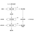
- FIG. 1 is a process diagram showing an example of the flow of the hydrometallurgical method of nickel oxide ore.
- a leaching process S1 is carried out in which sulfuric acid is added to a slurry of raw material nickel oxide ore under high temperature and high pressure to leach out, and a leachate obtained by the leaching process
- a sulfiding step S3 for obtaining a mixed sulfide of nickel and cobalt by adding a sulfiding agent to the obtained solution after the neutralization and subjecting the solution to a sulfiding treatment.
- Stir treatment is performed in a high pressure atmosphere to produce a leached slurry consisting of leachate and leachate residue.
- the treatment in the leaching step S1 may be performed in accordance with the conventionally known HPAL process.
- laterite ores such as limonite ore and saprolite ore can be used.
- the nickel content of laterite ore is about 0.8% by weight to 2.5% by weight, and is contained as a hydroxide or siliceous earth (magnesium silicate) mineral.
- solid-liquid separation is performed into a leachate containing nickel, cobalt and the like, and a leachate mainly composed of hematite.
- a leaching slurry is mixed with a washing solution, and subjected to a solid-liquid separation process by a solid-liquid separation facility such as a thickener.
- the leaching slurry is first diluted by the washing solution, and then the leaching residue in the slurry is concentrated as a thickener of thickener.
- solid-liquid separation tanks such as thickeners connected in multiple stages and perform solid-liquid separation while washing the leached slurry in multiple stages.
- the leaching solution obtained by solid-liquid separation of the leaching slurry is transferred to the neutralization step S2 of the next step, while the leaching residue is subjected to washing treatment and the like and discharged out of the system.
- neutralizing agent conventionally known ones can be used.
- calcium carbonate, calcium hydroxide, sodium hydroxide and the like can be used, and calcium carbonate is particularly preferable.
- the treatment in the neutralization step S2 is performed in a neutralization treatment plant.
- the neutralization processing plant includes a neutralization reaction tank that performs processing (neutralization processing) based on the neutralization reaction, and a solid-liquid separation device that separates the obtained post-neutralization slurry into a post-neutralization solution and neutralization sediment. And have.
- an aggregating agent is added in the liquid feed line for feeding the slurry after neutralization from the neutralization reaction tank to the solid-liquid separator in the neutralization treatment plant, and the fluid passes through the liquid feed line. After neutralization, the slurry is subjected to a solid-liquid separation treatment.
- the pH of the obtained solution after neutralization is in the range of 3.2 or more and 3.5 or less.
- the pH exceeds 3.5 hydroxides of nickel may occur, resulting in a recovery loss of nickel.
- solid-liquid separation may be reduced.
- the pH of the post-neutralization solution is less than 3.2, the amount of hydrogen sulfide gas that can be dissolved in the subsequent sulfurization step S3 decreases, which may reduce the efficiency of the sulfurization reaction.
- a sulfiding agent such as hydrogen sulfide gas, sodium sulfide, sodium hydrosulfide or the like is added to the obtained neutralized solution, and a sulfide containing nickel and cobalt with few impurity components (Silver-cobalt mixed sulfide) and a post-sulfiding solution stabilized at a low level of nickel concentration.
- the slurry of the nickel-cobalt mixed sulfide produced by the sulfidation reaction is subjected to separation treatment using a solid-liquid separation device (sedimentation separation device) such as thickener, etc. Separately from the bottom of the thickener.
- a solid-liquid separation device such as thickener, etc. Separately from the bottom of the thickener.
- the post-sulfiding solution which is an aqueous solution component is overflowed and recovered.
- the recovered after-sulfiding solution is subjected to washing treatment, (final) neutralization treatment and the like together with the leaching residue and the like and discharged out of the system.
- This neutralization treatment is performed, for example, in a neutralization treatment plant provided with a neutralization reaction tank for performing a neutralization reaction and a solid-liquid separation device for solid-liquid separation of the obtained slurry after neutralization.
- a neutralization treatment plant provided with a neutralization reaction tank for performing a neutralization reaction and a solid-liquid separation device for solid-liquid separation of the obtained slurry after neutralization.
- the post-neutralization slurry is sent from the neutralization reaction tank to the solid-liquid separator.
- a flocculant is added in the feed line, and the neutralized slurry which has passed through the feed line is subjected to solid-liquid separation.
- the neutralization treatment such that the pH of the obtained solution after neutralization is in a relatively high range, specifically in the range of about 3.2 to 3.5.
- the deterioration of the solid-liquid separation property of the obtained slurry after neutralization can be prevented.
- the pH of the obtained solution after neutralization can be set in the range of about 3.2 or more and 3.5 or less, it is possible to dissolve the hydrogen sulfide gas and the like added in the sulfurization treatment using the solution after neutralization as the initial solution. The amount can be increased, the sulfurization reaction efficiency can be improved, and nickel can be recovered with a high recovery rate.
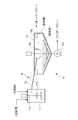
- FIG. 2 is a figure which shows an example of a structure of the neutralization process plant used at neutralization process S2.
- the neutralization processing plant 10 includes a neutralization reaction tank 11 that performs neutralization processing based on the neutralization reaction, and a solid-liquid separation device 12 that separates the obtained post-neutralization slurry into a post-neutralization solution and neutralization sediment. And have.
- the neutralization reaction tank 11 and the solid-liquid separation device 12 are connected by the liquid feed line 13, and the slurry after neutralization generated in the neutralization reaction tank 11 is the liquid feed line 13. It passes through and is charged into the solid-liquid separator 12.
- the neutralization reaction vessel 11 is, for example, a cylindrical vessel, and the leachate obtained through the leaching step S1 is charged into the vessel, and a neutralizing agent for neutralization treatment is added to the neutralization reaction vessel 11.
- a stirring apparatus is installed in the neutralization reaction tank 11, and causes the neutralization reaction to occur while stirring the leachate charged in the tank.
- FIG. 2 the example of the stirring apparatus provided with the stirring shaft 11a and the stirring blade 11b is shown.
- a liquid feed line 13 is connected to the neutralization reaction tank 11, and the neutralized slurry generated in the tank is transferred to the solid-liquid separator 12 through the liquid feed line 13.
- the solid-liquid separator 12 is, for example, a device such as a thickener.
- the solid-liquid separator 12 is charged with a slurry after neutralization reaction (slurry after neutralization) generated by the neutralization reaction in the neutralization reaction tank 11, and the slurry is neutralized to be a mother liquor for nickel recovery.
- the solution is separated into a post-liquid and a neutralized precipitate slurry consisting of impurity components.
- the solid-liquid separation device 12 overflows and transfers the post-neutralization solution separated from the neutralization precipitate by the solid-liquid separation and the feed well portion 12 a to which the slurry after neutralization, which is the solid-liquid separation target, is supplied And 12 b.
- the other end of the liquid feed line 13 connected to the neutralization reaction tank 11 is connected to the feed well 12a, and the neutralized slurry transferred from the neutralization reaction tank 11 is solidified via the feed well 12a. It is charged into the liquid separation device 12.
- the liquid phase (phase of the solution after neutralization) is on the top and the phase of the solid phase (neutralization slurry is on the bottom) by solid-liquid separation processing. ) Is formed, and the neutralization final solution constituting the liquid phase overflows and is transferred to, for example, an attached reservoir etc., while the neutralization precipitate slurry constituting the solid phase is the bottom of the solid-liquid separator 12 Taken from
- the neutralized sediment slurry extracted from the bottom portion is transferred by the transfer pump 12c, and appropriately repeated in a predetermined reaction tank or the like in the system.
- the liquid transfer line 13 is a liquid transfer line connecting the neutralization reaction tank 11 and the solid-liquid separator 12 in the neutralization processing plant 10, and the slurry after neutralization generated in the neutralization reaction tank 11 is solid-liquid The liquid is sent to the separation device 12.
- the liquid transfer line 13 is constituted by a weir, piping and the like.
- the liquid feed line 13 connects, for example, the neutralization reaction tank 11 located on the upper side at the position in the height direction, and the solid-liquid separation device 12 located on the lower side, and is installed in an inclined state due to the difference in height position. It is done. Therefore, the post-neutralization slurry transferred from the neutralization reaction tank 11 is sent to flow downstream along the inclined liquid feed line 13.
- the liquid feed line 13 is connected to the feedwell portion 12a of the solid-liquid separator 12, and the neutralized slurry is charged into the solid-liquid separator 12 through the feedwell portion 12a.
- a flocculant is added in the liquid feeding line 13 for feeding the slurry after neutralization from the neutralization reaction tank 11 to the solid-liquid separator 12.
- the slurry which has passed through the liquid feed line 13 is separated into solid and liquid.
- a chemical agent such as a coagulant and a coagulant made of a polymer is added.
- a coagulant and a coagulant are added to the inside of the neutralization reaction tank 11 and to the feed well portion 12a of the solid-liquid separator 12, and the neutralization treatment and solid-liquid separation are performed while stirring. I was processing.
- coagulants and coagulants made of high-molecular polymers have the property of capturing fine particles by their functional groups, it is advantageous to lower the drug concentration from the viewpoint of polymer dispersibility, and also high-molecular An aggregate substance formed by combining the polymer and the fine particles is easily destroyed by physical force by a stirring device or the like.
- the generated aggregate substance is hard to be destroyed since it is not affected by the power of the stirring device, and the solid-liquid separation property is improved. It can be enhanced.
- the coagulant When a coagulant is added in the liquid feed line 13, the coagulant is added to the neutralized slurry which passes through the liquid feed line 13 at a stage where the slurry is fed after neutralization in the liquid feed line 13. Can be added. Alternatively, a predetermined amount of coagulant is placed on the liquid feed line 13 before the slurry passes through the liquid feed line 13 after neutralization, and thereafter, on the liquid feed line 13 on which the coagulant is placed. The slurry may pass after neutralization.
- the addition position of the coagulant in the liquid delivery line 13 is not particularly limited as long as it is on the liquid delivery line 13, but it is relatively upstream from the viewpoint of effectively producing an aggregate substance in the liquid delivery line 13. It is preferable to add on the side (the side of the neutralization reaction tank 11). In addition, a coagulant may be added in multiple stages on the liquid feed line 13.
- the coagulant is not particularly limited, and cationic coagulants, non-ionic coagulants, nonionic coagulants, amphoteric coagulants and the like can be used. Among them, it is preferable to use a cationic coagulant from the viewpoint of further enhancing the solid-liquid separation property of the slurry after neutralization. Moreover, it is preferable to use a polymer flocculant from the viewpoint of being excellent in cohesiveness.
- cationic flocculants include polymer flocculants such as polyaminoalkyl methacrylate, polyethylene imine, halogenated polydiallyl ammonium, chitosan, urea-formalin resin and the like.
- anionic flocculant include sodium polyacrylate, partially hydrolyzed polyacrylamide, partially sulfomethylated polyacrylamide, poly (2-acrylamido) -2-methylpropane sulfate and the like.
- flocculant a polyacrylamide, a polyethylene oxide etc. are mentioned, for example.
- flocculant the copolymer etc. of acrylamide, an aminoalkyl methacrylate, and sodium acrylate are mentioned, for example.
- the addition amount of the coagulant is not particularly limited, and it is preferable to adjust appropriately according to the solid content contained in the slurry after neutralization, for example, 1 m 3 of the slurry after neutralization passing through the liquid feeding line 13 Therefore, it is preferable to set it to about 0.3 L to 1.0 L, and more preferable to set it to about 0.4 L to 0.7 L.
- a coagulant can be added together with the coagulant in the liquid feed line 13.
- a coagulant a cationic coagulant, an anionic coagulant, a nonionic coagulant, an amphoteric coagulant etc. can be used.
- polydiallyldimethyl ammonium chloride which is a cationic coagulant can be used. Even when a coagulant is added, the addition of the coagulant is performed in the liquid feed line 13.
- the solid-liquid separation property of the slurry after neutralization can be further enhanced by using the coagulant and the coagulant in combination and adding them in the liquid feed line 13.
- the reaction efficiency in the sulfidation treatment depends on the amount of the sulfiding agent dissolved in the solution after neutralization.
- the sulfurization reaction proceeds more efficiently, and nickel etc. in the solution after neutralization are effectively sulfided. can do.
- the amount of sulfurizing agent that can be dissolved depends on the pH of the solution after neutralization.
- the neutralization treatment can be performed such that the pH of the solution after neutralization is in the range of 3.2 or more and 3.5 or less. Even if it is, it can prevent effectively that the solid-liquid separation property of the slurry after neutralization deteriorates. That is, in the present embodiment, an aggregating agent is added in the liquid feeding line 13 for feeding the slurry after neutralization from the neutralization reaction tank 11 to the solid-liquid separator 12 and after the neutralization passing through the liquid feeding line 13 Since the slurry is subjected to solid-liquid separation, the solid content is efficiently aggregated and separated even if it is a post-neutralization slurry containing a post-neutralization solution having a pH of 3.2 or more and 3.5 or less. It is possible to obtain a post-neutralization solution with low turbidity.
- the numerical value measured by a turbidimeter (for example, a 2100P type scattered light turbidimeter manufactured by HACH) Can be less than 50 NTU.
- the recovery rate of nickel and cobalt recovered by the sulfidation treatment is correlated with the turbidity of the post-neutralization solution which is the starting solution of the sulfidation reaction. From this, the recovery of nickel and cobalt can be managed by the turbidity of the solution after neutralization (sulfurization reaction start solution). The lower the turbidity of the sulfurization reaction start solution (the higher the transparency), the more the aggregation of the solid proceeds and the more the adhesion water is washed. And since it is such a sulfurization reaction starting solution, nickel can be collect
- the solid content can be efficiently aggregated and separated, it is possible to obtain a post-neutralization solution with low turbidity, and a high recovery rate. Nickel can be recovered.
- Comparative Example 1 Conventional Method In the wet smelting process of nickel oxide ore, neutralization treatment was carried out using a leaching solution obtained by subjecting nickel oxide ore to leaching treatment with sulfuric acid using a neutralization treatment plant 10 as shown in FIG. .
- the neutralization processing plant 10 includes a neutralization reaction tank 11 for neutralizing the leachate, and a solid-liquid separator 12 for solid-liquid separation of the neutralized slurry into a post-neutralization solution and a neutralized precipitate.
- calcium carbonate was used as a neutralizing agent.
- Comparative Example 1 a cationic coagulant was added to the neutralization reaction tank 11, and a nonionic coagulant was added to the feedwell portion 12a of the solid-liquid separator (thickener) 12.
- Example 1 In Example 1, the cationic coagulant and the nonionic coagulant are added to the liquid feeding line 13 for feeding the slurry after neutralization from the neutralization reaction tank 11 to the solid-liquid separator 12. , And treated in the same manner as in Comparative Example 1. Specifically, arrow P in FIG. 2 is the addition position of the cationic coagulant and the nonionic coagulant.
- the turbidity of the supernatant liquid of the solid-liquid separator 12 was measured using a turbidimeter and was 37 NTU, which was slightly higher than that of Comparative Example 1, but the pH of the solution after neutralization was 3.27 It was possible to raise it.
- Example 2 In Example 2, the cationic flocculant is added to the feed line 13 (the position of the arrow P in FIG. 2) in the same manner as in Example 1 except that the drug used is changed to only the cationic flocculant. It was made to do.
- Comparative Example 2 was the same as Comparative Example 1 except that the pH of the post-neutralization solution obtained in the neutralization treatment in the neutralization reaction tank 11 was 3.31. That is, a cationic coagulant was added to the neutralization reaction tank 11, and a nonionic coagulant was added to the feed well portion 12 a of the solid-liquid separator 12.
- Comparative Example 3 Comparative Example 3 was the same as Example 2 except that the addition position of the cationic coagulant was changed to the inside of the neutralization reaction tank 11 and the inside of the solid-liquid separator 12. No flocculant was added to the liquid delivery line 13.
Landscapes
- Chemical & Material Sciences (AREA)
- Engineering & Computer Science (AREA)
- Manufacturing & Machinery (AREA)
- Materials Engineering (AREA)
- Mechanical Engineering (AREA)
- Metallurgy (AREA)
- Organic Chemistry (AREA)
- Geochemistry & Mineralogy (AREA)
- Life Sciences & Earth Sciences (AREA)
- Environmental & Geological Engineering (AREA)
- General Life Sciences & Earth Sciences (AREA)
- Geology (AREA)
- Chemical Kinetics & Catalysis (AREA)
- General Chemical & Material Sciences (AREA)
- Inorganic Chemistry (AREA)
- Manufacture And Refinement Of Metals (AREA)
- Separation Of Suspended Particles By Flocculating Agents (AREA)
Abstract
ニッケル酸化鉱石の湿式製錬方法において、浸出液に対する中和反応後のスラリーの固液分離性を悪化させることなく、プロセス液のpHを有効に高めることができ、そのプロセス液を用いて硫化反応を効率的に促進させることができる方法を提供する。 本発明に係るニッケル酸化鉱石の湿式製錬方法は、ニッケル酸化鉱石に硫酸を添加して浸出して得られた浸出液に対して中和反応槽11にて中和処理を施し、中和後スラリーを固液分離装置12にて固液分離して得られる中和後液に対して硫化処理を施すことによってニッケル及びコバルトを回収する処理を含む方法であって、中和反応槽11から固液分離装置12に中和後スラリーを送液する送液ライン13において凝集剤を添加し、その送液ライン13を通過した中和後スラリーを固液分離する。
Description
本発明は、ニッケル酸化鉱石の湿式製錬方法に関するものであり、より詳しくは、ニッケル酸化鉱石に硫酸を添加して得られた浸出液に対して中和処理を施し、中和後スラリーを固液分離して得られる中和後液に対して硫化処理を施すことによってニッケル及びコバルトを回収するニッケル酸化鉱石の湿式製錬方法に関する。
ニッケル酸化鉱石を原料とする湿式製錬方法においては、近年、高温高圧下において酸を用いて浸出する高圧酸浸出(HPAL:High Pressure Acid Leach)法による低ニッケル品位鉱石からの有価金属の回収方法が実用化されている。HPAL法によってニッケル酸化鉱石より浸出されたニッケル、コバルト等の有価金属は、加圧下でその有価金属を含む硫酸水溶液に硫化水素ガス等の硫化剤を添加して硫化処理を行うことにより、硫化物として回収される。
HPAL法では、ニッケルのほか、コバルト、マグネシウム、アルミニウム、鉄、クロムといった鉱石中に含まれている他の成分も、下記(1)式に従って浸出される。このうち、3価の金属イオンは、硫化処理を行う前に下記(2)式に示す中和反応(中和処理)によって除去されており、中和終液のpHは3.0~3.2前後に調整されている。そして、中和処理後、下記(3)式に従って硫化反応を生じさせることで、有価金属を硫化物として回収している。なお、中和処理は、炭酸カルシウム等の中和剤を用いて行われる。
MO+H2SO4=MSO4+H2O ・・・(1)
(M=Ni,Co,Mg,Al,Fe,Cr)
M2(SO4)3+4H2O=2MO(OH)+3H2SO4 ・・・(2)
(M3+=Al,Fe,Cr)
MSO4+H2S=MS+H2SO4 ・・・(3)
(M=Ni,Co,Zn)
MO+H2SO4=MSO4+H2O ・・・(1)
(M=Ni,Co,Mg,Al,Fe,Cr)
M2(SO4)3+4H2O=2MO(OH)+3H2SO4 ・・・(2)
(M3+=Al,Fe,Cr)
MSO4+H2S=MS+H2SO4 ・・・(3)
(M=Ni,Co,Zn)
さて、硫化反応を生じさせる硫化処理において、プロセス液中に溶存可能な硫化水素ガス量は、下記(4)及び(5)式に示す硫化水素の酸解離定数により計算することができる。また、その(4)及び(5)式に基づき、プロセス液中に溶存可能なSイオン濃度を下記(6)式で示すことができる。
H2S=H++HS- K1=1.0×10⁻⁷ ・・・(4)
HS-=H++S2- K2=1.0×10⁻¹⁴ ・・・(5)
[S2-]=(K1K2×[H2S])÷[H+]2 ・・・(6)
H2S=H++HS- K1=1.0×10⁻⁷ ・・・(4)
HS-=H++S2- K2=1.0×10⁻¹⁴ ・・・(5)
[S2-]=(K1K2×[H2S])÷[H+]2 ・・・(6)
上記(6)式において、[H2S]は飽和状態と仮定し0.10mol/Lであるとすると、pH3.1、pH3.3における[S2-]は、それぞれ下記(7)及び(8)式として示すことができる。
<pH3.1のとき>
[S2-]=[(1.0×10-7)×(1.0×10-14)×0.10mol/L]÷[10-3.1]2=1.58×10-15mol/L ・・・(7)
<pH3.3のとき>
[S2-]=[(1.0×10-7)×(1.0×10-14)×0.10mol/L]÷[10-3.3]2=3.98×10-15mol/L ・・・(8)
<pH3.1のとき>
[S2-]=[(1.0×10-7)×(1.0×10-14)×0.10mol/L]÷[10-3.1]2=1.58×10-15mol/L ・・・(7)
<pH3.3のとき>
[S2-]=[(1.0×10-7)×(1.0×10-14)×0.10mol/L]÷[10-3.3]2=3.98×10-15mol/L ・・・(8)
このことから、プロセス液中に溶存可能な硫化水素ガス量は、pHに依存することがわかる。例えば、pH3.1であるときの[S2-]=1.58×10⁻¹⁵mol/Lに対して、pH3.3のときは[S2-]=3.98×10-15mol/Lであるため、プロセス液中に溶存可能な硫化水素ガス濃度は約2.5倍に増加する。
このように、pH上昇によりプロセス液中に溶存可能な硫化水素ガス量が増加することから、硫化反応は極力高いpHで行うことが望ましくなる。しかしながら、プロセス液のpHが上昇すると、上述した(2)式に示す反応のほかに、下記(9)式に従って石膏(CaSO4)が生成する反応も進行する。石膏や一部の三価金属の澱物粒径は、非常に小さいことで知られており(例えばアルミニウム)、石膏等の生成により、固液分離処理における制御性の悪化を招くことがある。
H2SO4+CaCO3+H2O=CaSO4・H2O+CO2 ・・・(9)
H2SO4+CaCO3+H2O=CaSO4・H2O+CO2 ・・・(9)
そのため、中和処理では、固液分離性が悪化しない程度のpHに制御する必要があり、pH3.0~3.2程度までの上昇にとどめているのが現状であり、高pH領域において、固液分離性を向上させる技術の開発が求められていた。
固液分離性を向上させる手段としては、中和反応で生成する微粒子を捕捉する凝集剤や凝結剤といった高分子ポリマーを反応溶液に添加する方法が一般的である。しかしながら、高pH領域において固液分離性を保つことは容易ではなく、プロセス液組成に適した薬剤の選定が求められる。
また、その他の解決策として、直接、硫化処理においてNaSHを添加することによってpHを上昇させる方法が考えられるが、余剰なコストが必要になるという問題がある。
ここで、特許文献1には、ニッケル酸化鉱石の湿式製錬プロセスにおいて、脱亜鉛処理で形成される亜鉛硫化物の分離に際しての濾過性を改善し、濾布の寿命を延長させるために、中和反応後のスラリーに凝集剤を添加する方法が開示されている。しかしながら、この特許文献1には、硫化反応においてpHを上昇させること、そしてそのpH上昇により硫化反応の効率性を高め、硫化物の収率を向上させることについて何ら示されていない。
また、特許文献2には、ニッケル酸化鉱石の湿式製錬プロセスにおいて、濾過不良や濾過速度の低下を抑制して中和澱物を効果的に分離除去するために、ニッケル及びコバルトを含む浸出液に対してマグネシウム酸化物を中和剤として用いて中和処理を施し、その中和スラリーに対してカチオン系凝集剤を添加して中和澱物を分離除去する方法が開示されている。しかしながら、この特許文献2においても、硫化反応においてpHを上昇させること、そしてそのpH上昇により硫化反応の効率性を高め、硫化物の収率を向上させることについては何ら示されていない。
本発明は、このような実情に鑑みて提案されたものであり、ニッケル酸化鉱石の湿式製錬方法において、浸出液に対する中和反応後のスラリーの固液分離性を悪化させることなく、プロセス液のpHを有効に高めることができ、そのプロセス液を用いて硫化反応を効率的に促進させることができる方法を提供することを目的とする。
本発明者は、上述した課題を解決するために鋭意検討を重ねた。その結果、中和処理により得られた中和後スラリーを中和反応槽から固液分離装置に送液する送液ライン内に凝集剤を添加し、その送液ラインを通過した中和後スラリーを固液分離するようにすることで、pHを有効に高めながら固液分離性を向上させることができることを見出し、本発明を完成するに至った。
(1)本発明の第1の発明は、ニッケル酸化鉱石に硫酸を添加して浸出して得られた浸出液に対して中和反応槽にて中和処理を施し、中和後スラリーを固液分離装置にて固液分離して得られる中和後液に対して硫化処理を施すことによってニッケル及びコバルトを回収する処理を含むニッケル酸化鉱石の湿式製錬方法であって、前記中和反応槽から前記固液分離装置に中和後スラリーを送液する送液ラインにおいて凝集剤を添加し、該送液ラインを通過した該中和後スラリーを固液分離する、ニッケル酸化鉱石の湿式製錬方法である。
(2)本発明の第2の発明は、第1の発明において、前記送液ラインにおいて、さらに凝結剤を添加する、ニッケル酸化鉱石の湿式製錬方法である。
(3)本発明の第3の発明は、第1又は第2の発明において、前記凝集剤は、カチオン系凝集剤である、ニッケル酸化鉱石の湿式製錬方法である。
(4)本発明の第4の発明は、第1乃至第3のいずれかの発明において、前記中和処理では、得られる中和後液のpHを3.2以上3.5以下とする、ニッケル酸化鉱石の湿式製錬方法である。
(5)本発明の第5の発明は、第1乃至第4のいずれかの発明において、前記中和処理では、中和剤として炭酸カルシウムを用いる、ニッケル酸化鉱石の湿式製錬方法である。
(6)本発明の第6の発明は、第4又は第5の発明において、前記固液分離装置内における上澄み液の濁度が、50NTU以下である、ニッケル酸化鉱石の湿式製錬方法である。
本発明によれば、ニッケル酸化鉱石の湿式製錬方法において、浸出液に対する中和反応後のスラリーの固液分離性を悪化させることなく、プロセス液のpHを有効に高めることができ、そのプロセス液を用いて硫化反応を効率的に促進させることができる方法を提供することができる。
以下、本発明の具体的な実施形態(以下、「本実施の形態」という)について、図面を参照しながら詳細に説明する。なお、本発明は、以下の実施形態に限定されるものではなく、本発明の要旨を変更しない範囲で種々の変更が可能である。また、本明細書において、「x~y」(x、yは任意の数値)との表記は、特に断らない限り「x以上y以下」の意味である。
≪1.ニッケル酸化鉱石の湿式製錬方法≫
本実施の形態に係るニッケル酸化鉱石の湿式製錬方法は、原料であるニッケル酸化鉱石に対して高温高圧の条件下で硫酸により浸出処理を施し、得られた浸出液に対して中和処理を施して不純物を除去したのち、その浸出液に含まれるニッケル及びコバルトを硫化物として回収するものである。なお、以下の湿式製錬方法は、硫酸溶液を用いた高温加圧酸浸出法(HPAL法)によりニッケル及びコバルトを回収する形態を具体例として示す。
本実施の形態に係るニッケル酸化鉱石の湿式製錬方法は、原料であるニッケル酸化鉱石に対して高温高圧の条件下で硫酸により浸出処理を施し、得られた浸出液に対して中和処理を施して不純物を除去したのち、その浸出液に含まれるニッケル及びコバルトを硫化物として回収するものである。なお、以下の湿式製錬方法は、硫酸溶液を用いた高温加圧酸浸出法(HPAL法)によりニッケル及びコバルトを回収する形態を具体例として示す。
図1は、ニッケル酸化鉱石の湿式製錬方法の流れの一例を示す工程図である。図1に示すように、この湿式製錬方法は、原料のニッケル酸化鉱石のスラリーに対して高温高圧下で硫酸を添加して浸出処理を施す浸出工程S1と、浸出処理により得られた浸出液に対して中和処理を施す中和工程S2と、得られた中和後液に硫化剤を添加して硫化処理を施し、ニッケル及びコバルトの混合硫化物を得る硫化工程S3と、を含む。
(1)浸出工程
浸出工程S1では、例えば高温加圧容器(オートクレーブ)等を用いて、ニッケル酸化鉱石のスラリーに硫酸を添加し、例えば、240℃~260℃程度の高温、3MPa~5MPa程度の高い圧力雰囲気で撹拌処理を施し、浸出液と浸出残渣とからなる浸出スラリーを生成する。なお、浸出工程S1における処理は、従来知られているHPALプロセスに従って行えばよい。
浸出工程S1では、例えば高温加圧容器(オートクレーブ)等を用いて、ニッケル酸化鉱石のスラリーに硫酸を添加し、例えば、240℃~260℃程度の高温、3MPa~5MPa程度の高い圧力雰囲気で撹拌処理を施し、浸出液と浸出残渣とからなる浸出スラリーを生成する。なお、浸出工程S1における処理は、従来知られているHPALプロセスに従って行えばよい。
ニッケル酸化鉱石としては、リモナイト鉱及びサプロライト鉱等のいわゆるラテライト鉱を用いることができる。ラテライト鉱のニッケル含有量は、0.8重量%~2.5重量%程度であり、水酸化物又はケイ苦土(ケイ酸マグネシウム)鉱物として含有される。
浸出工程S1では、得られた浸出液と浸出残渣とからなる浸出スラリーを洗浄しながら、ニッケルやコバルト等を含む浸出液と、ヘマタイトを主成分とする浸出残渣とに固液分離する。この固液分離処理では、例えば、浸出スラリーを洗浄液と混合し、シックナー等の固液分離設備によって固液分離処理を施す。具体的には、先ず、浸出スラリーが洗浄液により希釈され、次に、スラリー中の浸出残渣がシックナーの沈降物として濃縮される。なお、この固液分離処理では、シックナー等の固液分離槽を多段に連結させて用い、浸出スラリーを多段洗浄しながら固液分離することが好ましい。
なお、浸出スラリーを固液分離して得られた浸出液は次工程の中和工程S2へと移送され、一方で、浸出残渣は洗浄処理等が施されて系外に排出される。
(2)中和工程
中和工程S2では、得られた浸出液の酸化を抑制しながら、中和剤を添加して浸出液中の余剰酸を中和するとともに、浸出液中に含まれる3価の鉄やアルミニウム等の不純物成分を中和澱物とする中和処理を施す。この中和工程S2では、中和処理して得られた中和処理後のスラリー(中和後スラリー)中の中和澱物を沈降分離させ、シックナー等の固液分離装置により固液分離処理を施し、中和澱物を分離除去する。これにより、中和澱物スラリーと、ニッケル及びコバルトを回収するための母液となる中和後液とが分離される。
中和工程S2では、得られた浸出液の酸化を抑制しながら、中和剤を添加して浸出液中の余剰酸を中和するとともに、浸出液中に含まれる3価の鉄やアルミニウム等の不純物成分を中和澱物とする中和処理を施す。この中和工程S2では、中和処理して得られた中和処理後のスラリー(中和後スラリー)中の中和澱物を沈降分離させ、シックナー等の固液分離装置により固液分離処理を施し、中和澱物を分離除去する。これにより、中和澱物スラリーと、ニッケル及びコバルトを回収するための母液となる中和後液とが分離される。
中和剤としては、従来公知のもの使用することができ、例えば、炭酸カルシウム、消石灰、水酸化ナトリウム等を用いることができ、特に、炭酸カルシウムが好ましい。
中和工程S2における処理は、中和処理プラントにて行われる。中和処理プラントは、中和反応に基づく処理(中和処理)を行う中和反応槽と、得られた中和後スラリーを中和後液と中和澱物とに分離する固液分離装置と、を備えている。
ここで、本実施の形態では、中和処理プラントにおける、中和反応槽から固液分離装置へと中和後スラリーを送液する送液ラインにおいて凝集剤を添加し、その送液ラインを通過した中和後スラリーに対して固液分離処理を施すことを特徴としている。
また、この中和処理では、好ましくは、得られる中和後液のpHが3.2以上3.5以下の範囲となるようにする。pHが3.5を超えると、ニッケルの水酸化物が生じることがあり、ニッケルの回収ロスとなる。また、固液分離性が低下することがある。一方で、中和後液のpHが3.2未満になると、次工程の硫化工程S3において添加する硫化水素ガスの溶存可能量が減少し、硫化反応の効率が低下する可能性がある。
なお、中和処理プラントの構成例を含め、詳しくは後述する。
(3)硫化工程
硫化工程S3では、中和工程S2により得られた中和後液に硫化水素ガス等の硫化剤を添加して硫化処理を施し、ニッケルを含む硫化物と硫化後液とを得る。この硫化処理により、ニッケル、コバルト、亜鉛等は硫化物となり、スカンジウム等は硫化後液に含まれることになる。
硫化工程S3では、中和工程S2により得られた中和後液に硫化水素ガス等の硫化剤を添加して硫化処理を施し、ニッケルを含む硫化物と硫化後液とを得る。この硫化処理により、ニッケル、コバルト、亜鉛等は硫化物となり、スカンジウム等は硫化後液に含まれることになる。
具体的に、硫化工程S3では、得られた中和後液に対して、硫化水素ガス、硫化ナトリウム、水素化硫化ナトリウム等の硫化剤を添加し、不純物成分の少ないニッケル及びコバルトを含む硫化物(ニッケル・コバルト混合硫化物)と、ニッケル濃度を低い水準で安定させた硫化後液とを生成させる。
硫化工程S3における硫化処理では、硫化反応により生成したニッケル・コバルト混合硫化物のスラリーに対してシックナー等の固液分離装置(沈降分離装置)を用いた分離処理を施し、ニッケル・コバルト混合硫化物をシックナー底部より分離回収する。一方、水溶液成分である硫化後液についてはオーバーフローさせて回収する。なお、回収した硫化後液は、浸出残渣等と共に洗浄処理や(最終)中和処理等が施されて系外に排出される。
≪2.中和後スラリーに対する固液分離≫
上述したように、ニッケル酸化鉱石の湿式製錬方法においては、浸出工程S1にて生成した浸出液に対して中和工程S2にて中和処理を施すことにより、浸出液中に含まれる余剰酸の中和と不純物成分の分離除去を行う。具体的には、浸出液に炭酸カルシウム等の中和剤を添加して不純物成分の沈澱物(中和澱物)を生成させたのち、得られた中和後スラリーを固液分離することによって中和後液と中和澱物とに分離する。
上述したように、ニッケル酸化鉱石の湿式製錬方法においては、浸出工程S1にて生成した浸出液に対して中和工程S2にて中和処理を施すことにより、浸出液中に含まれる余剰酸の中和と不純物成分の分離除去を行う。具体的には、浸出液に炭酸カルシウム等の中和剤を添加して不純物成分の沈澱物(中和澱物)を生成させたのち、得られた中和後スラリーを固液分離することによって中和後液と中和澱物とに分離する。
この中和処理は、例えば、中和反応を行う中和反応槽と、得られた中和後スラリーを固液分離する固液分離装置と、を備えた中和処理プラントにて行われる。このとき、本実施の形態では、中和反応槽にて中和処理を施して中和後スラリーを生成させたのち、中和反応槽から固液分離装置へと中和後スラリーを送液する送液ラインにおいて凝集剤を添加し、その送液ラインを通過した中和後スラリーを固液分離する。
このような方法によれば、得られる中和後液のpHを比較的高めの範囲、具体的には3.2以上3.5以下程度の範囲となるように中和処理を施すことができ、一方で、得られる中和後スラリーの固液分離性の悪化を防ぐことができる。そして、得られる中和後液のpHが3.2以上3.5以下程度の範囲に設定できることから、その中和後液を始液として用いる硫化処理において、添加する硫化水素ガス等の溶存可能量を高めることができ、硫化反応効率を向上させて、高い回収率でニッケルを回収することができる。
[中和処理プラントについて]
図2は、中和工程S2にて使用する中和処理プラントの構成の一例を示す図である。中和処理プラント10は、中和反応に基づく中和処理を行う中和反応槽11と、得られた中和後スラリーを中和後液と中和澱物とに分離する固液分離装置12と、を備えている。中和処理プラント10においては、中和反応槽11と固液分離装置12とが送液ライン13により接続されており、中和反応槽11にて生成した中和後スラリーは送液ライン13を通過して固液分離装置12内に装入される。
図2は、中和工程S2にて使用する中和処理プラントの構成の一例を示す図である。中和処理プラント10は、中和反応に基づく中和処理を行う中和反応槽11と、得られた中和後スラリーを中和後液と中和澱物とに分離する固液分離装置12と、を備えている。中和処理プラント10においては、中和反応槽11と固液分離装置12とが送液ライン13により接続されており、中和反応槽11にて生成した中和後スラリーは送液ライン13を通過して固液分離装置12内に装入される。
(中和反応槽)
中和反応槽11は、例えば円筒形の容器であり、浸出工程S1を経て得られた浸出液が槽内に装入され、また中和処理のための中和剤が添加されて、中和反応を生じさせる。中和反応槽11には、撹拌装置が設置されており、槽内に装入された浸出液を撹拌しながら中和反応を生じさせる。なお、図2では、撹拌軸11aと、撹拌羽根11bと、を備えた撹拌装置の例を示している。
中和反応槽11は、例えば円筒形の容器であり、浸出工程S1を経て得られた浸出液が槽内に装入され、また中和処理のための中和剤が添加されて、中和反応を生じさせる。中和反応槽11には、撹拌装置が設置されており、槽内に装入された浸出液を撹拌しながら中和反応を生じさせる。なお、図2では、撹拌軸11aと、撹拌羽根11bと、を備えた撹拌装置の例を示している。
中和反応槽11には、送液ライン13が接続されており、槽内で生成した中和後スラリーが送液ライン13を介して固液分離装置12に移送される。
(固液分離装置)
固液分離装置12は、例えばシックナー等の装置である。固液分離装置12には、中和反応槽11における中和反応により生成した中和反応後のスラリー(中和後スラリー)が装入され、そのスラリーを、ニッケル回収用の母液となる中和後液と不純物成分からなる中和澱物スラリーとに分離する。
固液分離装置12は、例えばシックナー等の装置である。固液分離装置12には、中和反応槽11における中和反応により生成した中和反応後のスラリー(中和後スラリー)が装入され、そのスラリーを、ニッケル回収用の母液となる中和後液と不純物成分からなる中和澱物スラリーとに分離する。
固液分離装置12は、固液分離対象である中和後スラリーが供給されるフィードウェル部12aと、固液分離により中和澱物と分離された中和後液をオーバーフローさせて移送するオーバーフロー樋12bと、を備えている。中和反応槽11に接続された送液ライン13は、他端がフィードウェル部12aに接続されており、中和反応槽11から移送された中和後スラリーがフィードウェル部12aを介して固液分離装置12内に装入される。
図2に模式的に示すように、固液分離装置12においては、固液分離処理により、上部に液体相(中和後液の相)が、下部に固体相(中和澱物スラリーの相)が形成され、液体相を構成する中和終液がオーバーフローして例えば付設された貯留槽等に移送され、一方で、固体相を構成する中和澱物スラリーは固液分離装置12の底部から抜き出される。
なお、底部から抜き出された中和澱物スラリーは、移送ポンプ12cにより移送され、適宜系内の所定の反応槽等に繰り返される。
(送液ライン)
送液ライン13は、中和処理プラント10における、中和反応槽11と固液分離装置12とを連結する送液ラインであり、中和反応槽11にて生成した中和後スラリーを固液分離装置12へと送液する。送液ライン13は、樋や配管等により構成されている。
送液ライン13は、中和処理プラント10における、中和反応槽11と固液分離装置12とを連結する送液ラインであり、中和反応槽11にて生成した中和後スラリーを固液分離装置12へと送液する。送液ライン13は、樋や配管等により構成されている。
送液ライン13は、例えば、高さ方向の位置において上側にある中和反応槽11と、下側にある固液分離装置12とを連結し、その高さ位置の違いにより傾斜した状態で設置されている。したがって、中和反応槽11から移送される中和後スラリーは、傾斜した送液ライン13に沿って下流側に流れるように送られる。
なお、送液ライン13は、固液分離装置12のフィードウェル部12aに接続され、中和後スラリーをそのフィードウェル部12aを介して固液分離装置12内に装入する。
[中和後スラリーに対する固液分離について]
本実施の形態では、上述した構成を有する中和処理プラント10において、中和反応槽11から固液分離装置12へと中和後スラリーを送液する送液ライン13において凝集剤を添加することを特徴としており、その送液ライン13を通過した中和後スラリーを固液分離する。
本実施の形態では、上述した構成を有する中和処理プラント10において、中和反応槽11から固液分離装置12へと中和後スラリーを送液する送液ライン13において凝集剤を添加することを特徴としており、その送液ライン13を通過した中和後スラリーを固液分離する。
ここで、中和後スラリーに対する固液分離処理では、その固液分離性を向上させるために、高分子ポリマーからなる凝集剤や凝結剤といった薬剤が添加される。
従来、中和処理プラント10においては、中和反応槽11の槽内や固液分離装置12のフィードウェル部12aに凝集剤や凝結剤を添加し、撹拌を施しながら中和処理や固液分離処理を行っていた。ところが、高分子ポリマーからなる凝集剤や凝結剤は、その官能基によって微粒子を捕捉するという性質を有するため、ポリマーの分散性の観点から薬剤濃度を低くする方が有利であり、また、高分子ポリマーと微粒子とが結合して生成する凝集体物質は、撹拌装置等による物理的な力によって容易に破壊されてしまう。
本発明者の研究の結果、少なくとも凝集剤を添加するにあたっては、中和反応槽11から固液分離装置12へと中和後ラリーを送液する送液ライン13内に添加するようにすることで、固液分離装置12における中和後スラリーの固液分離性が向上することが見出された。具体的に、本実施の形態においては、図2中の矢印Pで示すように、送液ライン13内に凝集剤を添加する。
このように、送液ライン13において少なくとも凝集剤を添加することによって、その送液ライン13内を通過する中和後スラリー中に均一に分散させることができ、凝集効果を高めることができる。また、送液ライン13内においては、中和反応槽11や固液分離装置12のように撹拌装置による動力の影響を受けないため、生成した凝集体物質が破壊され難く、固液分離性を高めることができる。
凝集剤を送液ライン13において添加する際、送液ライン13内を中和後スラリーが送液されている途中の段階で、その送液ライン13を通過する中和後スラリーに対して凝集剤を添加することができる。または、中和後スラリーが送液ライン13を通過する前に、その送液ライン13上に所定量の凝集剤を載置しておき、その後、凝集剤を載置した送液ライン13上を中和後スラリーが通過するようにしてもよい。
送液ライン13における凝集剤の添加位置としては、送液ライン13上であればいずれの箇所でもよく特に限定されないが、送液ライン13において有効に凝集体物質を生成させる観点から、比較的上流側(中和反応槽11側)にて添加することが好ましい。また、送液ライン13上において多段階に亘って凝集剤を添加してもよい。
凝集剤としては、特に限定されず、カチオン系凝集剤、ニオン系凝集剤、ノニオン系凝集剤、両性系凝集剤等を用いることができる。その中でも、中和後スラリーの固液分離性をより高める観点から、カチオン系凝集剤を用いることが好ましい。また、凝集性に優れる観点から、高分子凝集剤を用いることが好ましい。
カチオン系凝集剤としては、例えば、ポリアミノアルキルメタクリレート、ポリエチレンイミン、ハロゲン化ポリジアリルアンモニウム、キトサン、尿素-ホルマリン樹脂等の高分子凝集剤が挙げられる。また、アニオン系凝集剤としては、例えば、ポリアクリル酸ナトリウム、ポリアクリルアミド部分加水分解物、部分スルホメチル化ポリアクリルアミド、ポリ(2-アクリルアミド)-2-メチルプロパン硫酸塩等が挙げられる。また、ノニオン系凝集剤としては、例えば、ポリアクリルアミド、ポリエチレンオキシド等が挙げられる。また、両性系凝集剤としては、例えば、アクリルアミドとアミノアルキルメタクリレートとアクリル酸ナトリウムの共重合体等が挙げられる。
凝集剤の添加量としては、特に限定されず、中和後スラリーに含まれる固形分量に応じて適宜調整することが好ましいが、例えば、送液ライン13を通過する中和後スラリー1m3に対して、0.3L~1.0L程度とすることが好ましく、0.4L~0.7L程度とすることがより好ましい。
また、送液ライン13において、凝集剤と併せて、凝結剤を添加することができる。凝結剤としては、カチオン系凝結剤、アニオン凝結剤、ノニオン系凝結剤、両性系凝結剤等を用いることができる。例えば、カチオン系凝結剤であるポリジアリルジメチル塩化アンモニム等を用いることができる。なお、凝結剤を添加する場合でも、その凝結剤の添加は、送液ライン13において行う。
このように、凝集剤と凝結剤とを併用し、それらを送液ライン13において添加することによって、中和後スラリーの固液分離性をより一層に高めることができる。
≪3.中和後液を用いた硫化工程≫
上述したような、中和後スラリーに対する固液分離処理の後、中和澱物を分離して得られた中和後液を硫化反応始液として硫化処理を施す(硫化工程)。硫化処理においては、中和後液に硫化水素ガス等の硫化剤を添加して硫化反応を生じさせて、ニッケル、コバルトの硫化物を生成させる。
上述したような、中和後スラリーに対する固液分離処理の後、中和澱物を分離して得られた中和後液を硫化反応始液として硫化処理を施す(硫化工程)。硫化処理においては、中和後液に硫化水素ガス等の硫化剤を添加して硫化反応を生じさせて、ニッケル、コバルトの硫化物を生成させる。
硫化処理における反応効率は、中和後液中に添加する硫化剤の溶存量に依存する。例えば硫化剤として硫化水素ガスを用いた反応では、溶液中に溶存し得る硫化水素ガス量が多いほど硫化反応が効率的に進行し、中和後液中のニッケル等を効果的に硫化物にすることができる。一方で、硫化剤の溶存可能量は、中和後液のpHに依存する。
この点においては、本実施の形態においては、中和後液のpHが3.2以上3.5以下の範囲となるように中和処理を施すことができ、このようなpHに制御した場合であっても、中和後スラリーの固液分離性が悪化することを効果的に防ぐことができる。すなわち、本実施の形態では、中和反応槽11から固液分離装置12に中和後スラリーを送液する送液ライン13において凝集剤を添加し、その送液ライン13を通過した中和後スラリーを固液分離するようにしていることから、pHが3.2以上3.5以下の中和後液を含む中和後スラリーであっても、固形分を効率的に凝集させて分離することができ、濁度の低い中和後液を得ることができる。
具体的に、固液分離装置12内における上澄み液(液体相)である中和後液の濁度としては、濁度計(例えば、HACH社製2100P型散乱光式濁度計)による測定数値で50NTU以下とすることができる。
ここで、硫化処理により回収されるニッケル及びコバルトの回収率は、その硫化反応の始液となる中和後液の濁度と相関関係があることが知られている。このことから、ニッケル及びコバルトの回収率は、中和後液(硫化反応始液)の濁度で管理することができる。硫化反応始液の濁度が低いほど(透明度が高いほど)、固形分の凝集が進行し、また付着水の洗浄が十分に行われていることを意味する。そして、このような硫化反応始液であることにより、高い回収率でニッケルを回収することができ、また生成する硫化物に含まれる不純物含有量も極めて低く抑えることができる。
この点においては、上述したように本実施の形態においては、固形分を効率的に凝集させて分離することができることから、濁度の低い中和後液を得ることができ、高い回収率でニッケルを回収することができる。
以下、本発明の実施例を示してより具体的に説明するが、本発明は以下の実施例に何ら限定されるものではない。
[比較例1:従来法]
ニッケル酸化鉱石の湿式製錬プロセスにおいて、ニッケル酸化鉱石に対し硫酸で浸出処理を施して得られた浸出液を用い、図2に示すような中和処理プラント10を使用して中和処理を実行した。なお、中和処理プラント10は、浸出液を中和する中和反応槽11と、中和後スラリーを中和後液と中和澱物とに固液分離する固液分離装置12とを備える。また、中和反応槽11での中和処理においては、中和剤として炭酸カルシウムを用いた。
ニッケル酸化鉱石の湿式製錬プロセスにおいて、ニッケル酸化鉱石に対し硫酸で浸出処理を施して得られた浸出液を用い、図2に示すような中和処理プラント10を使用して中和処理を実行した。なお、中和処理プラント10は、浸出液を中和する中和反応槽11と、中和後スラリーを中和後液と中和澱物とに固液分離する固液分離装置12とを備える。また、中和反応槽11での中和処理においては、中和剤として炭酸カルシウムを用いた。
このとき、比較例1では、カチオン系凝結剤を中和反応槽11に添加し、ノニオン系凝集剤を固液分離装置(シックナー)12のフィードウェル部12aに添加した。
処理後、固液分離装置12の上澄み液の濁度を濁度計(2100P型散乱光式濁度計,HACH社製)を用いて測定したところ、23NTUであった。また、中和後液のpHは3.17まで上昇させることができた。このようにして得られた中和後液を用いて硫化水素ガスにより硫化処理(硫化工程)を実行したところ、中和後液(硫化反応始液)中に溶存可能な硫化水素ガス量は2.19×10⁻¹⁶mol/Lであり、有価金属(ニッケル、コバルト)の回収率は97.3%であった。
[実施例1]
実施例1では、カチオン系凝結剤とノニオン系凝集剤とを、中和反応槽11から固液分離装置12へと中和後スラリーを送液する送液ライン13に添加するようしたこと以外は、比較例1と同様にして処理した。具体的に、図2中の矢印Pがカチオン系凝結剤及びノニオン系凝集剤の添加位置である。
実施例1では、カチオン系凝結剤とノニオン系凝集剤とを、中和反応槽11から固液分離装置12へと中和後スラリーを送液する送液ライン13に添加するようしたこと以外は、比較例1と同様にして処理した。具体的に、図2中の矢印Pがカチオン系凝結剤及びノニオン系凝集剤の添加位置である。
処理後、固液分離装置12の上澄み液の濁度を濁度計を用いて測定したところ、37NTUであり、比較例1と比べて若干上昇したものの、中和後液のpHは3.27まで上昇させることができた。そして、このようにして得られた中和後液を用いて硫化水素ガスにより硫化処理(硫化工程)を実行したところ、中和後液(硫化反応始液)中に溶存可能な硫化水素ガス量は3.47×10⁻¹⁶mol/Lで、有価金属(ニッケル、コバルト)の回収率は97.9%となり、比較例1よりも有価金属の回収率を高めることができた。
[実施例2]
実施例2では、使用する薬剤をカチオン系凝集剤のみに変更したこと以外は、実施例1と同様にしてそのカチオン系凝集剤を送液ライン13(図2中の矢印Pの位置)に添加するようにした。
実施例2では、使用する薬剤をカチオン系凝集剤のみに変更したこと以外は、実施例1と同様にしてそのカチオン系凝集剤を送液ライン13(図2中の矢印Pの位置)に添加するようにした。
処理後、固液分離装置12の上澄み液の濁度を濁度計を用いて測定したところ、48NTUであり、中和後液のpHは3.32まで上昇させることができた。そして、このようにして得られた中和後液を用いて硫化水素ガスにより硫化処理(硫化工程)を実行したところ、中和後液(硫化反応始液)中に溶存可能な硫化水素ガス量は4.37×10⁻¹⁶mol/Lであり、有価金属(ニッケル、コバルト)の回収率は98.2%となった。
[比較例2]
比較例2では、中和反応槽11における中和処理において得られる中和後液のpHが3.31となるように処理したこと以外は、比較例1と同様にした。すなわち、カチオン系凝結剤を中和反応槽11に添加し、ノニオン系凝集剤を固液分離装置12のフィードウェル部12aに添加した。
比較例2では、中和反応槽11における中和処理において得られる中和後液のpHが3.31となるように処理したこと以外は、比較例1と同様にした。すなわち、カチオン系凝結剤を中和反応槽11に添加し、ノニオン系凝集剤を固液分離装置12のフィードウェル部12aに添加した。
処理後、固液分離装置12の上澄み液の濁度を濁度計を用いて測定したところ、100NTUを大幅に超える値となり、このような濁度の悪化は後工程に影響を及ぼすため、連続運転を停止させた。
[比較例3]
比較例3では、カチオン系凝集剤の添加位置を、中和反応槽11内及び固液分離装置12内に変更した以外は、実施例2と同様とした。なお、送液ライン13には凝集剤を添加しなかった。
比較例3では、カチオン系凝集剤の添加位置を、中和反応槽11内及び固液分離装置12内に変更した以外は、実施例2と同様とした。なお、送液ライン13には凝集剤を添加しなかった。
処理後、固液分離装置12の上澄み液の濁度を濁度計を用いて測定したところ、63NTUまで上昇した。一方で、中和後液のpHは3.22までしか上昇しなかった。そして、このようにして得られた中和後液を用いて硫化水素ガスにより硫化処理(硫化工程)を実行したところ、中和後液(硫化反応始液)中に溶存可能な硫化水素ガス量は2.75×10⁻¹⁶mol/Lであり、有価金属(ニッケル、コバルト)の回収率は97.6%となった。

以上の結果から、中和反応槽から固液分離装置へと中和後スラリーを送液する送液ラインにおいて凝集剤を添加するようにすることで、優れた固液分離性を保持したまま、中和後液のpHを有効に上昇させることができ、硫化処理によるニッケル等の有価金属の回収率を高めることができることがわかった。
Claims (6)
- ニッケル酸化鉱石に硫酸を添加して浸出して得られた浸出液に対して中和反応槽にて中和処理を施し、中和後スラリーを固液分離装置にて固液分離して得られる中和後液に対して硫化処理を施すことによってニッケル及びコバルトを回収する処理を含むニッケル酸化鉱石の湿式製錬方法であって、
前記中和反応槽から前記固液分離装置に中和後スラリーを送液する送液ラインにおいて凝集剤を添加し、該送液ラインを通過した該中和後スラリーを固液分離する
ニッケル酸化鉱石の湿式製錬方法。 - 前記送液ラインにおいて、さらに凝結剤を添加する
請求項1に記載のニッケル酸化鉱石の湿式製錬方法。 - 前記凝集剤は、カチオン系凝集剤である
請求項1又は2に記載のニッケル酸化鉱石の湿式製錬方法。 - 前記中和処理では、得られる中和後液のpHを3.2以上3.5以下とする
請求項1乃至3のいずれか1項に記載のニッケル酸化鉱石の湿式製錬方法。 - 前記中和処理では、中和剤として炭酸カルシウムを用いる
請求項1乃至4のいずれか1項に記載のニッケル酸化鉱石の湿式製錬方法。 - 前記固液分離装置内における上澄み液の濁度が、50NTU以下である
請求項4又は5に記載のニッケル酸化鉱石の湿式製錬方法。
Priority Applications (1)
| Application Number | Priority Date | Filing Date | Title |
|---|---|---|---|
| PH1/2020/500279A PH12020500279B1 (en) | 2017-09-11 | 2018-08-08 | Hydrometallurgical method for nickel oxide mineral ore |
Applications Claiming Priority (2)
| Application Number | Priority Date | Filing Date | Title |
|---|---|---|---|
| JP2017174034A JP6551481B2 (ja) | 2017-09-11 | 2017-09-11 | ニッケル酸化鉱石の湿式製錬方法 |
| JP2017-174034 | 2017-09-11 |
Publications (1)
| Publication Number | Publication Date |
|---|---|
| WO2019049593A1 true WO2019049593A1 (ja) | 2019-03-14 |
Family
ID=65633908
Family Applications (1)
| Application Number | Title | Priority Date | Filing Date |
|---|---|---|---|
| PCT/JP2018/029778 Ceased WO2019049593A1 (ja) | 2017-09-11 | 2018-08-08 | ニッケル酸化鉱石の湿式製錬方法 |
Country Status (3)
| Country | Link |
|---|---|
| JP (1) | JP6551481B2 (ja) |
| PH (1) | PH12020500279B1 (ja) |
| WO (1) | WO2019049593A1 (ja) |
Families Citing this family (2)
| Publication number | Priority date | Publication date | Assignee | Title |
|---|---|---|---|---|
| JP7183503B2 (ja) * | 2018-08-30 | 2022-12-06 | 住友金属鉱山株式会社 | 高濃度鉱石スラリーの製造方法 |
| JP7115170B2 (ja) * | 2018-09-12 | 2022-08-09 | 住友金属鉱山株式会社 | ニッケル酸化鉱石の処理方法及び該処理方法を含んだニッケルコバルト混合硫化物の製造方法 |
Citations (7)
| Publication number | Priority date | Publication date | Assignee | Title |
|---|---|---|---|---|
| JPH0760009A (ja) * | 1993-06-16 | 1995-03-07 | Sumitomo Chem Co Ltd | 沈降式固液分離装置 |
| JP2005213343A (ja) * | 2004-01-29 | 2005-08-11 | Tomooka Kaken Kk | 有機凝結剤および高分子凝集剤 |
| WO2008003160A1 (en) * | 2006-07-03 | 2008-01-10 | Curlook Enterprises Inc. | Metal recovery system as applied to the high pressure leaching of limonitic nickel laterite ores |
| JP2010075802A (ja) * | 2008-09-24 | 2010-04-08 | Kurita Water Ind Ltd | 有機凝結剤及び排水処理方法並びに汚泥脱水方法 |
| US20140150886A1 (en) * | 2012-11-30 | 2014-06-05 | Total E&P Canada Ltd. | Two-stage flocculation of fluid fine tailings |
| JP2014101548A (ja) * | 2012-11-20 | 2014-06-05 | Sumitomo Metal Mining Co Ltd | 中和スラリーの沈降分離方法、並びにニッケル酸化鉱石の湿式製錬方法 |
| US20150053623A1 (en) * | 2013-08-22 | 2015-02-26 | Psmg, Llc | Particle suspensions of floculating polymer powders |
-
2017
- 2017-09-11 JP JP2017174034A patent/JP6551481B2/ja active Active
-
2018
- 2018-08-08 WO PCT/JP2018/029778 patent/WO2019049593A1/ja not_active Ceased
- 2018-08-08 PH PH1/2020/500279A patent/PH12020500279B1/en unknown
Patent Citations (7)
| Publication number | Priority date | Publication date | Assignee | Title |
|---|---|---|---|---|
| JPH0760009A (ja) * | 1993-06-16 | 1995-03-07 | Sumitomo Chem Co Ltd | 沈降式固液分離装置 |
| JP2005213343A (ja) * | 2004-01-29 | 2005-08-11 | Tomooka Kaken Kk | 有機凝結剤および高分子凝集剤 |
| WO2008003160A1 (en) * | 2006-07-03 | 2008-01-10 | Curlook Enterprises Inc. | Metal recovery system as applied to the high pressure leaching of limonitic nickel laterite ores |
| JP2010075802A (ja) * | 2008-09-24 | 2010-04-08 | Kurita Water Ind Ltd | 有機凝結剤及び排水処理方法並びに汚泥脱水方法 |
| JP2014101548A (ja) * | 2012-11-20 | 2014-06-05 | Sumitomo Metal Mining Co Ltd | 中和スラリーの沈降分離方法、並びにニッケル酸化鉱石の湿式製錬方法 |
| US20140150886A1 (en) * | 2012-11-30 | 2014-06-05 | Total E&P Canada Ltd. | Two-stage flocculation of fluid fine tailings |
| US20150053623A1 (en) * | 2013-08-22 | 2015-02-26 | Psmg, Llc | Particle suspensions of floculating polymer powders |
Also Published As
| Publication number | Publication date |
|---|---|
| PH12020500279A1 (en) | 2021-01-25 |
| JP2019049033A (ja) | 2019-03-28 |
| PH12020500279B1 (en) | 2022-11-09 |
| JP6551481B2 (ja) | 2019-07-31 |
Similar Documents
| Publication | Publication Date | Title |
|---|---|---|
| JP5644878B2 (ja) | 固液分離処理方法、並びにニッケル酸化鉱石の湿式製錬方法 | |
| JP6750698B2 (ja) | ニッケル高圧浸出残渣の固液分離方法 | |
| JP7183503B2 (ja) | 高濃度鉱石スラリーの製造方法 | |
| JP7095606B2 (ja) | 湿式製錬法によるニッケル酸化鉱石からのニッケルコバルト混合硫化物の製造方法 | |
| JP6984191B2 (ja) | ニッケル高圧浸出残渣の固液分離方法 | |
| JP5692458B1 (ja) | 固液分離処理方法、並びにニッケル酸化鉱石の湿式製錬方法 | |
| JP5348267B2 (ja) | 脱亜鉛処理プラント及び脱亜鉛プラントの操業方法、並びにニッケル酸化鉱石の湿式製錬方法 | |
| JP6551481B2 (ja) | ニッケル酸化鉱石の湿式製錬方法 | |
| JP2016113703A (ja) | ニッケル酸化鉱石の湿式製錬における中和方法 | |
| JP6828359B2 (ja) | ニッケル酸化鉱の湿式製錬方法 | |
| JP6202083B2 (ja) | 硫化剤の除去方法 | |
| JP7115170B2 (ja) | ニッケル酸化鉱石の処理方法及び該処理方法を含んだニッケルコバルト混合硫化物の製造方法 | |
| JP7005909B2 (ja) | 中和処理方法、及び中和終液の濁度低減方法 | |
| CN104955968A (zh) | 中和浆料的沉降分离方法、以及氧化镍矿石的湿式冶炼方法 | |
| JP7506356B2 (ja) | 高濃度スラリーを得るためのシックナーの管理方法 | |
| JP2019157236A (ja) | 固液分離処理方法、ニッケル酸化鉱石の湿式製錬方法 | |
| JP2020028858A (ja) | ニッケル酸化鉱石の湿式製錬プロセスにおける最終中和方法 | |
| JP7039936B2 (ja) | ニッケル高圧浸出残渣の固液分離方法 | |
| JP2018079435A (ja) | 中和処理方法 | |
| JP7585804B2 (ja) | 固液分離処理方法、ニッケル酸化鉱石の湿式製錬方法 | |
| JP7585921B2 (ja) | ニッケル酸化鉱石の湿式製錬方法 | |
| JP2020076130A (ja) | ニッケル酸化鉱石の湿式製錬方法 | |
| JP7147362B2 (ja) | ニッケル酸化鉱石の湿式製錬法における臭気低減方法 | |
| JP2019077928A (ja) | 中和処理方法およびニッケル酸化鉱石の湿式製錬方法 | |
| JP2019210514A (ja) | 固液分離処理方法 |
Legal Events
| Date | Code | Title | Description |
|---|---|---|---|
| 121 | Ep: the epo has been informed by wipo that ep was designated in this application |
Ref document number: 18854555 Country of ref document: EP Kind code of ref document: A1 |
|
| NENP | Non-entry into the national phase |
Ref country code: DE |
|
| 122 | Ep: pct application non-entry in european phase |
Ref document number: 18854555 Country of ref document: EP Kind code of ref document: A1 |