WO2019049486A1 - 固定子コア製造方法、固定子コア製造方法によって製造された固定子コアを備えたモータ、固定子コア製造装置及び積層部材の製造方法 - Google Patents
固定子コア製造方法、固定子コア製造方法によって製造された固定子コアを備えたモータ、固定子コア製造装置及び積層部材の製造方法 Download PDFInfo
- Publication number
- WO2019049486A1 WO2019049486A1 PCT/JP2018/025009 JP2018025009W WO2019049486A1 WO 2019049486 A1 WO2019049486 A1 WO 2019049486A1 JP 2018025009 W JP2018025009 W JP 2018025009W WO 2019049486 A1 WO2019049486 A1 WO 2019049486A1
- Authority
- WO
- WIPO (PCT)
- Prior art keywords
- stator core
- divided
- laminate
- manufacturing
- steel plate
- Prior art date
- Legal status (The legal status is an assumption and is not a legal conclusion. Google has not performed a legal analysis and makes no representation as to the accuracy of the status listed.)
- Ceased
Links
Images






Classifications
-
- H—ELECTRICITY
- H02—GENERATION; CONVERSION OR DISTRIBUTION OF ELECTRIC POWER
- H02K—DYNAMO-ELECTRIC MACHINES
- H02K1/00—Details of the magnetic circuit
- H02K1/06—Details of the magnetic circuit characterised by the shape, form or construction
- H02K1/12—Stationary parts of the magnetic circuit
- H02K1/18—Means for mounting or fastening magnetic stationary parts on to, or to, the stator structures
-
- H—ELECTRICITY
- H02—GENERATION; CONVERSION OR DISTRIBUTION OF ELECTRIC POWER
- H02K—DYNAMO-ELECTRIC MACHINES
- H02K15/00—Processes or apparatus specially adapted for manufacturing, assembling, maintaining or repairing of dynamo-electric machines
- H02K15/02—Processes or apparatus specially adapted for manufacturing, assembling, maintaining or repairing of dynamo-electric machines of stator or rotor bodies
Definitions
- the present invention relates to a stator core manufacturing method, a motor including a stator core manufactured by the stator core manufacturing method, a stator core manufacturing apparatus, and a method of manufacturing a laminated member.
- a method of manufacturing a stator core of a motor there is known a method of punching a steel plate into a shape of a stator core by a pressing device or the like and laminating a plurality of punched formed steel plates in a thickness direction.
- the stator core is divided into a plurality of pieces in the circumferential direction, thereby increasing the number of turns of the stator coil with respect to the teeth while increasing work efficiency. Ways to improve are also known.
- Patent Document 1 As a method of manufacturing a stator core as described above, a stator core formed by laminating a plurality of annular plate members is divided along the circumferential direction to be divided cores A method of manufacturing a brushless motor for an electric power steering device, which forms a unit, is known. In this manufacturing method, after winding the winding individually on the divided core units, the divided core units are rejoined in the same combination as at the time of division to obtain a stator.
- An object of the present invention is to manufacture a stator core capable of easily and easily dividing a laminate obtained by laminating a plurality of formed steel plates in the thickness direction without peeling of steel plates constituting the laminate. To provide a way.
- a method of manufacturing a stator core according to an embodiment of the present invention is a method of manufacturing a stator core in which a plurality of divided cores in which a plurality of plate-shaped divided core pieces are stacked are annularly arranged around a central axis.
- this stator core manufacturing method after a part of the steel plate is punched in the shape of the divided core piece in the axial direction of the central axis, pushback processing is performed to return the punched divided core piece to the original position of the steel plate.
- the laminated body obtained by laminating a plurality of formed steel sheets in the thickness direction is simple without the steel plates constituting the laminated body being peeled off. And it can be divided easily.
- FIG. 1 is a view schematically showing a schematic configuration of a motor according to the embodiment in a cross section including a central axis.
- FIG. 2 is a perspective view showing a schematic configuration of a stator core.
- FIG. 3 is a flowchart showing a method of manufacturing a stator core.
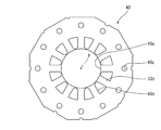
- FIG. 4 is a plan view of the electromagnetic steel sheet before forming the split core piece forming portion.
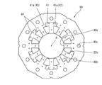
- FIG. 5 is a plan view showing a schematic configuration of a formed steel plate.
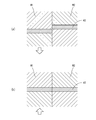
- FIG. 6 is a view schematically showing (a) a state in which the first tool is moved with respect to the second tool, and (b) a state in which the first tool is returned to the original position in pushback processing. is there.
- FIG. 6 is a view schematically showing (a) a state in which the first tool is moved with respect to the second tool, and (b) a state in which the first tool is returned to the original position in pushback processing. is there.
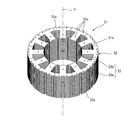
- FIG. 7 is a perspective view showing a schematic configuration of a formed steel plate laminate in which a plurality of formed steel plates are stacked in the thickness direction.
- FIG. 8 is a top view showing a schematic configuration of a stator core laminate after cutting processing.
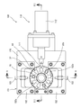
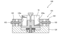
- FIG. 9 is a top view showing a schematic configuration of the stator core division device.
- FIG. 10 is a cross-sectional view taken along line XX in FIG. 11 is a cross-sectional view taken along line XI-XI in FIG.
- FIG. 12 is a perspective view showing a stator core laminate divided into a plurality of divided cores.
- a direction parallel to the central axis of the rotor is "axial direction”
- a direction perpendicular to the central axis is “radial direction”
- a direction along an arc centered on the central axis is “circumferential direction” It is called respectively.
- this direction is not intended to limit the use direction of the motor according to the present invention.
- FIG. 1 shows a schematic configuration of a motor 1 according to an embodiment of the present invention.
- the motor 1 includes a rotor 2, a stator 3, a housing 4, and a cover plate 5.
- the rotor 2 rotates around the central axis P with respect to the stator 3.
- the motor 1 is a so-called inner rotor type motor in which the rotor 2 is disposed rotatably around the central axis P in the cylindrical stator 3.
- the rotor 2 includes a shaft 20, a rotor core 21, and a magnet 22.
- the rotor 2 is disposed radially inward of the stator 3 and is rotatable relative to the stator 3.
- the rotor core 21 has a cylindrical shape extending along the central axis P.
- the rotor core 21 is configured by laminating a plurality of electromagnetic steel plates formed in a predetermined shape in the thickness direction.
- a shaft 20 extending along the central axis P is fixed to the rotor core 21 in an axially penetrating state. Thereby, the rotor core 21 rotates with the shaft 20. Further, in the present embodiment, on the outer peripheral surface of the rotor core 21, the plurality of magnets 22 are disposed at predetermined intervals in the circumferential direction.
- the magnet 22 may be a ring magnet connected in the circumferential direction.
- the stator 3 is housed in the housing 4.
- the stator 3 is cylindrical, and the rotor 2 is disposed radially inward. That is, the stator 3 is disposed to face the rotor 2 in the radial direction.
- the rotor 2 is disposed radially inward of the stator 3 so as to be rotatable about a central axis P.
- the stator 3 includes a stator core 31, a stator coil 36, and a bracket 37.
- the stator core 31 has a cylindrical shape extending in the axial direction.
- the stator core 31 has a plurality of electromagnetic steel plates formed in a predetermined shape and stacked in the thickness direction.
- the stator core 31 has a plurality of divided cores 32 as described later.
- the stator core 31 has a plurality of teeth 31 b extending radially inward from a cylindrical yoke 31 a.
- the stator coil 36 is wound on a bracket 37 made of an insulating material (for example, an insulating resin material) mounted on the teeth 31 b of the stator core 31.
- the brackets 37 are disposed on both axial end faces of the stator core 31.
- the stator core 31 has a plurality of divided cores 32 disposed annularly around the central axis P. In the example shown in FIG. 2, the stator core 31 has twelve divided cores 32. Each split core 32 has a split yoke portion 32a that constitutes a part of a cylindrical yoke 31a, and one tooth 31b.
- the number of divided cores 32 constituting the stator core 31 is appropriately determined according to the number of teeth 31 b. That is, if the number of teeth of the stator core is more than 12, the number of divided cores is more than 12. On the other hand, if the number of teeth in the stator core is less than 12, the number of split cores is less than 12.
- the split core 32 has a plurality of plate-like split core pieces 33 stacked.
- the plurality of split core pieces 33 that constitute the split core 32 have the same shape.
- the split core piece 33 has a split yoke piece 33a that constitutes a part of the split yoke portion 32a and a tooth piece 33b that constitutes a part of the teeth 31b.
- the plurality of split core pieces 33 are connected to each other by caulking portions 33 c provided on the split yoke pieces 33 a and the teeth pieces 33 b in a state of being stacked in the thickness direction.
- the circumferential end of the divided yoke portion 32a is in contact with the circumferential end of the divided yoke portion 32a adjacent to the divided yoke portion 32a in the circumferential direction.
- the annular yoke 31 a of the stator core 31 is configured by the divided yoke portions 32 a of the plurality of divided cores 32.
- the housing 4 is cylindrical and extends along the central axis P.
- the housing 4 has a cylindrical shape having an internal space capable of housing the rotor 2 and the stator 3 therein.
- the housing 4 has a cylindrical side wall 4a and a bottom 4b covering one axial end of the side wall 4a.
- the opening on the other side in the axial direction of the housing 4 is covered by a cover plate 5.
- the housing 4 and the cover plate 5 are made of, for example, a material containing iron.
- the cover plate 5 may be fixed to the housing 4 by, for example, a bolt or the like, or may be fixed by a method such as press fitting or adhesion.
- the housing 4 and the cover plate 5 may be comprised not only by the material containing iron but other materials, such as aluminum (aluminium alloy is included).
- FIG. 3 is a flowchart showing an example of a method of manufacturing the stator core 31.
- FIG. 4 is a plan view of the electromagnetic steel sheet 40 before the split core piece forming portion 41 is formed.
- FIG. 5 is a plan view showing a formed steel plate 50 in which a split core piece forming portion 41 to be the split core pieces 33 is formed.
- FIG. 6 is a diagram schematically showing push back processing.
- FIG. 7 is a perspective view showing a formed steel plate laminate 60 in which a plurality of formed steel plates 50 are stacked in the thickness direction.
- FIG. 8 is a plan view showing a stator core laminate 70 obtained by cutting the formed steel plate laminate 60.
- a circular central hole 40a is punched out of a magnetic steel sheet which is a magnetic material. This process is the central hole punching process shown in FIG. 3 (step S1). The center of the central hole 40 a coincides with the central axis P of the motor 1.
- step S2 a plurality of slots 40b are punched around the central hole 40a to form a plurality of tooth pieces 33b surrounding the central hole 40a.
- This process is the slot punching process shown in FIG. 3 (step S2).
- central hole punching process and slot punching process are performed by press working.
- the central hole punching process and the slot punching process are the same as those of the conventional stator core manufacturing method, and thus the detailed description is omitted.
- FIG. 4 shows the electromagnetic steel sheet 40 (hereinafter referred to as a steel sheet) in which the central hole 40a and the slot 40b are formed as described above.
- the some through-hole 40c is pierced by the outer peripheral side.
- the punching of the outer shape of the steel plate 40 and the punching of the through holes 40c may be performed simultaneously with the above-mentioned central hole punching step or slot punching step, or before, after, or after the central hole punching step and slot punching step. You may go between
- the split core piece forming portion 41 to be the split core piece 33 is provided on the outer peripheral side of the central hole 40a.
- a plurality of rings are molded side by side.
- the split core piece molding portion 41 has a split yoke piece molding portion 41a to be a split yoke piece 33a and a teeth piece 33b.
- the split yoke piece molding portion 41a is molded.
- the steel plate 40 is punched in the thickness direction with the shape of the split yoke piece 33a outside the teeth piece 33b with respect to the center of the central hole 40a.
- the so-called push back processing is performed to return the punched out part to its original position. This process is the push back process shown in FIG. 3 (step S3).
- push back processing has a first tool W1 having a pair of upper and lower tools sandwiching a part of a steel plate 40 in the thickness direction, and a pair of upper and lower tools sandwiching a part of the steel plate 40 in the thickness direction It is performed using the second tool W2.
- the first tool W1 is movable in the thickness direction of the steel plate 40 with respect to the second tool W2.
- the first tool W1 has the same shape as the divided yoke piece 33a.
- the moving distance of the first tool W1 with respect to the second tool W2 may be a moving distance for separating the steel plate 40, or may be a moving distance for not separating the steel plate 40.
- the first tool W1 is returned to the original position by moving the first tool W1 to the other side in the thickness direction of the steel plate 40 with respect to the second tool W2.
- the part pinched by 1st tool W1 among the steel plates 40 is engage
- the divided yoke piece molding portion 41a has the extrusion portion 42 in which the above-described pushback processing is performed and the non-extrusion portion 43 which is not extruded. As shown in FIG. 5, the extruded portions 42 and the non-extruded portions 43 are alternately positioned in the circumferential direction.
- a dividing portion 44 is formed between the pushing portion 42 and a portion which is not pushed out by the push back process. That is, in the boundary between the extruded portion 42 and the non-extruded portion 43 and the boundary between the extruded portion 42 and the outer peripheral side of the steel plate 40, the dividing portion 44 is formed by push back processing. In the dividing portion 44, the pushing portion 42 is held by friction with respect to the other portion.
- the step of forming the formed steel plate 50 in which a plurality of divided core piece forming portions 41 to be divided core pieces 33 are annularly arranged by push back processing as described above corresponds to the push back step.
- the divided yoke piece forming portion 41a As described above, by forming the divided yoke piece forming portion 41a by the pushback process, the divided yoke piece forming portion 41a is not bent at the time of processing. Thereby, the generation of residual stress and residual strain due to processing can be suppressed. Therefore, the dimensional accuracy of the split core pieces 33, that is, the stator core 31 can be enhanced. Further, since the disturbance of the flow of the magnetic flux in the split core piece 33 can be suppressed by suppressing the generation of the residual stress and the residual strain as described above, it is possible to suppress the deterioration of the magnetic characteristics of the stator core 31.
- the crimped portion 33c is formed on the split yoke piece forming portion 41a and the teeth piece 33b.
- the caulking portion 33c is obtained by forming a convex portion having a recess on the surface on the other side in the thickness direction while protruding in one of the thickness direction on the split yoke piece forming portion 41a and the teeth piece 33b.
- the step of forming the caulking portion 33c is a caulking portion forming step shown in FIG. 3 (step S4).
- step S5 This process is the laminating process shown in FIG. 3 (step S5).
- the formed steel plate laminate 60 is cut at a cutting position X (a position shown by a broken line in FIG. 7) on the outer peripheral side of the divided yoke piece forming portion 41a by electric discharge machining or the like, as shown in top view in FIG.
- the stator core laminate 70 is obtained.
- This process is a processing process shown in FIG. 3 (step S6).
- the cutting position X at the time of cutting the formed steel plate laminate 60 is a position on the inner peripheral side of the outer peripheral end of the divided yoke piece forming portion 41 a.
- the lamination step of laminating the formed steel plates 50 in the thickness direction to obtain the formed steel plate laminate 60, and the processing step of cutting the formed steel plate laminate 60 to obtain the stator core laminate 70 are the laminate forming steps.
- stator core laminate 70 can be divided into a plurality of divided cores 32 as described later.
- FIG. 9 is a top view showing a schematic configuration of a stator core division device 100 (stator core manufacturing device) for dividing the stator core laminate 70 into a plurality of divided cores 32.
- FIG. 10 is a cross-sectional view taken along line XX in FIG. 11 is a cross-sectional view taken along line XI-XI in FIG.
- FIG. 12 is a perspective view showing the stator core laminate 70 divided into a plurality of divided cores 32. As shown in FIG.
- the stator core division device 100 supports the holding portion 101 holding the stator core laminate 70, the external force applying portion 110 applying a force to the side surface of the stator core laminate 70, the holding portion 101 and the external force applying portion 110. And a frame 120.
- the holding portion 101 has a pair of holding members 102 which sandwich a part of the outer peripheral side of the cylindrical stator core laminate 70 in the radial direction.
- the pair of holding members 102 can be advanced and retracted with respect to the frame 120 by the screws 103.
- the pair of holding members 102 have contact surfaces 102 a that are arc-shaped in top view and contact the outer peripheral side of the rotor core laminate 70.
- the external force application unit 110 has a pin 111 for applying a force of a component in a direction perpendicular to the stacking direction to the stator core laminate 70, and an actuator 112 for advancing and retracting the pin 111. That is, the pin 111 of the external force applying unit 110 applies the force of the component in the vertical direction to the outer peripheral side of the stator core laminate 70 held by the holding unit 101. Thereby, the stator core laminate 70 can be deformed in the radial direction. Therefore, the divided portions 44 located between the divided yoke piece molding portions 41a adjacent to each other in the stator core laminated body 70 are separated, and the stator core laminated body 70 is divided into a plurality of divided cores 32 as shown in FIG. It is divided.
- Body 70 can be divided into multiple split cores 32.
- stator core laminate 70 when the stator core laminate 70 is divided into a plurality of divided cores 32, the pins 111 of the external force applying portion 110 sequentially with respect to a plurality of places in the circumferential direction of the stator core laminate 70. Apply the force of the vertical component. Thereby, the stator core laminate 70 can be divided into the plurality of divided cores 32 quickly and easily.
- stator core laminate 70 When the force of the component in the vertical direction is applied to a plurality of locations in the circumferential direction of the stator core laminate 70, a plurality of split core piece forming portions annularly arranged in the circumferential direction in the stator core laminate 70 It is preferable to apply the force of the component of the said perpendicular direction to the outer peripheral side of the stator core laminated body 70 with respect to the some division
- the stator core laminate 70 can be efficiently divided into the plurality of divided cores 32.
- the split core piece molding portions 41 separated from each other mean the split core piece molding portions 41 which are not adjacent to each other in the circumferential direction.
- the pin 111 of the external force applying portion 110 is positioned to face the central portion of the stator core laminate 70 in the stacking direction.
- the force of the component in the vertical direction can be applied to the central portion of the stator core laminate 70 in the stacking direction by the pins 111.
- the stator core laminate 70 can be efficiently divided into the plurality of divided cores 32.
- stator core laminate 70 can be efficiently divided into the plurality of divided cores 32.
- the pin 111 of the external force applying portion 110 is stacked on the stator core with respect to the boundary portion (the dividing portion 44) of the plurality of split core piece forming portions 41 arranged annularly in the circumferential direction in the stator core laminate 70.
- the force of the vertical component is applied to the outer peripheral side of the body 70.
- the force of the component in the direction perpendicular to the lamination direction of the formed steel plate 50 is applied to the outer peripheral side of the stator core laminate 70 to divide the stator core laminate 70 into a plurality of divided cores 32
- the corresponding step corresponds to the dividing step (step S7 in FIG. 3).
- a plurality of stator core laminates 70 obtained by laminating formed steel plates 50 press-formed into the shape of divided core pieces 33 in the pushback process in the thickness direction in the pushback process are provided with teeth 31b. Can be easily divided into divided cores 32.
- the force of the component in the direction perpendicular to the laminating direction of the formed steel plate 50 is applied to the outer peripheral side of the stator core laminated body 70 to suppress peeling of the steel plates constituting the stator core laminated body 70 it can.
- stator core laminate 70 when the stator core laminate 70 is divided into a plurality of divided cores 32, the stator core laminate 70 is perpendicular to the lamination direction at a plurality of locations on the outer peripheral side of the stator core laminate 70. Apply the component power of direction.
- the force of the component in the vertical direction may be applied to one point on the outer peripheral side of the stator core laminate.
- the force of the component in the vertical direction may be applied to a predetermined range in the stacking direction on the outer peripheral side of the stator core stack.
- the stator core laminate can be more efficiently divided into the plurality of divided cores 32 by applying a force to a predetermined range in the lamination direction of the stator core laminate.
- stator core laminated body 70 when the stator core laminated body 70 is divided into the plurality of divided cores 32, the stator core laminated body 70 is separated from each other among the plurality of divided core piece forming portions 41 annularly arranged in the circumferential direction.
- the force of the component in the vertical direction is applied to the outer peripheral side of the stator core laminate 70 with respect to the plurality of split core piece forming portions 41.
- the force of the component in the vertical direction may be applied to the outer peripheral side of the stator core laminate with respect to the split core piece forming portions 41 adjacent in the circumferential direction in the stator core laminate.
- the force of the component in the vertical direction is applied to the central portion of the stator core laminate 70 in the stacking direction.
- the force of the component in the vertical direction may be applied.
- the stator core laminate 70 when the stator core laminate 70 is divided into a plurality of divided cores 32, the stator core laminate is used for the portion between the teeth 33b adjacent in the circumferential direction in the stator core laminate 70.
- the force of the vertical component is applied to the outer peripheral side of 70.
- the stator core laminate 70 has the above-described outer peripheral side of the stator core laminate 70 with respect to the boundary portion (dividing portion 44) of the plurality of divided core piece forming portions 41 annularly arranged in the circumferential direction. Apply the force of the vertical component.
- the force of the component in the vertical direction may be applied to any position on the outer peripheral side of the stator core laminate 70 as long as the stator core laminate 70 can be divided into the plurality of divided cores 32.
- the stator core laminate 70 is obtained by cutting the formed steel plate laminate 60 at the cutting position X in the processing step.
- the steel plate constituting the stator core laminate may be formed. Thereby, the manufacturing process can be omitted in the method of manufacturing the stator core.
- the motor is a so-called permanent magnet motor.
- the rotor has a magnet.
- the motor 1 may be a motor having no magnet, such as an induction machine, a reluctance motor, a switched reluctance motor, or a winding field type motor.
- the manufacturing method of the above-mentioned embodiment may be applied to the manufacturing method of the lamination member by which the division part in which a plurality of plate-like division pieces were laminated was arranged annularly centering on the central axis.
- the manufacturing method of the laminated member is a divided piece which becomes the divided piece by pushback processing of punching out a part of the steel plate in the thickness direction in the shape of the divided piece and returning the punched part back to the original position of the steel plate.
- the divided pieces correspond to the divided core pieces 33 in the above-described embodiment, and the divided portions correspond to the divided cores 32 in the above-described embodiment.
- stacking member is corresponded to the stator core 31 in the above-mentioned embodiment, and the said division
- molding part is equivalent to the division
- the present invention is applicable to a method of manufacturing a stator core in which a plurality of divided core pieces in which plate-shaped divided core pieces are stacked are annularly arranged around a central axis.
Landscapes
- Engineering & Computer Science (AREA)
- Power Engineering (AREA)
- Manufacturing & Machinery (AREA)
- Iron Core Of Rotating Electric Machines (AREA)
- Manufacture Of Motors, Generators (AREA)
Abstract
【課題】成形鋼板が厚み方向に複数枚積層された積層体を、簡単且つ容易に分割可能な固定子コアの製造方法を提供する。【解決手段】固定子コア製造方法は、鋼板の一部を分割コア片の形状で中心軸の軸方向に打ち抜いた後、該打ち抜いた分割コア片を鋼板の元の位置に戻すプッシュバック加工により、分割コア片となる分割コア片成形部が、環状に複数並んだ成形鋼板を形成するプッシュバック工程S3と、成形鋼板を、軸方向に積層して円筒状の固定子コア積層体を得る積層体形成工程(積層工程S5及び加工工程S6)と、固定子コア積層体の外周側に対し、成形鋼板の積層方向に対して垂直方向の成分の力を加えて、固定子コア積層体を前記複数の分割コアに分割する分割工程S7と、を有する。
Description
本発明は、固定子コア製造方法、固定子コア製造方法によって製造された固定子コアを備えたモータ、固定子コア製造装置及び積層部材の製造方法に関する。
モータの固定子コアを製造する方法として、プレス装置等によって鋼板を固定子コアの形状に打ち抜いて、打ち抜かれた成形鋼板を厚み方向に複数枚積層する方法が知られている。また、固定子コアのティースに固定子コイルを巻線する際に、前記固定子コアを周方向に複数に分割することにより、前記ティースに対する前記固定子コイルの巻回数を増加させつつ作業効率を向上する方法も知られている。
上述のような固定子コアの製造方法として、例えば特許文献1に開示されるように、環状のプレート部材を複数枚積層して形成した固定子コアを、周方向に沿って分割して分割コアユニットを形成する、電動パワーステアリング装置用ブラシレスモータ製造方法が知られている。この製造方法では、前記分割コアユニットに対し個別に巻線を巻き付けた後、分割コアユニット同士を分割時と同じ組み合わせで再接合することにより固定子を得る。
なお、前記特許文献1に開示されている製造方法では、ハーフブランク加工によってコアピースの接合部を半抜き状態にした後、該接合部をポンチ及びダイスによって押し戻す。これにより、破断面にバリが生じることなく、前記接合部を接合線に沿って切断することができる。また、前記接合部が凹凸嵌合構造を有することにより、前記接合部で分離することなく、プレート部材を厚み方向に積層することができる。
上述の特許文献1に開示されている構成のように、鋼板をコアピース(分割コア片)の形状に打ち抜いた後、該打ち抜いた部分を前記鋼板の元の位置に戻す加工(以下、プッシュバック加工という)を用いて固定子コアを製造する場合、プッシュバック加工によって形成された成形鋼板を積層することによって得られた積層体を、複数の分割コアに分割する必要がある。
前記特許文献1には開示されていないが、前記成形鋼板を厚み方向に複数枚積層することによって得られた積層体を分割する際に、該積層体の積層方向の一方の端部におけるティース間に、くさびを打ち込んで前記積層体を周方向に分割する方法が考えられる。
しかしながら、このような分割方法では、前記積層体に対して内側から斜め外方に向かって力が加わるため、前記積層体を構成する鋼板が剥がれる可能性がある。
本発明の目的は、成形鋼板を厚み方向に複数枚積層することによって得られた積層体を、該積層体を構成する鋼板が剥離することなく、簡単且つ容易に分割可能な固定子コアの製造方法を提供することにある。
本発明の一実施形態に係る固定子コア製造方法は、板状の分割コア片が複数枚積層された分割コアが、中心軸を中心に環状に配置された固定子コアの製造方法である。この固定子コア製造方法は、鋼板の一部を前記分割コア片の形状で前記中心軸の軸方向に打ち抜いた後、該打ち抜いた前記分割コア片を前記鋼板の元の位置に戻すプッシュバック加工により、前記分割コア片となる分割コア片成形部が環状に複数並んだ成形鋼板を形成するプッシュバック工程と、前記成形鋼板を軸方向に積層して、円筒状の積層体を得る積層体形成工程と、前記積層体の外周側に対し、前記成形鋼板の積層方向に対して垂直方向の成分の力を加えて、前記積層体を前記複数の分割コアに分割する分割工程と、を有する。
本発明の一実施形態に係る固定子コア製造方法によれば、成形鋼板を厚み方向に複数枚積層することによって得られた積層体を、該積層体を構成する鋼板が剥離することなく、簡単且つ容易に分割することができる。
以下、図面を参照し、本発明の実施の形態を詳しく説明する。なお、図中の同一または相当部分については同一の符号を付してその説明は繰り返さない。また、各図中の構成部材の寸法は、実際の構成部材の寸法及び各構成部材の寸法比率等を忠実に表したものではない。
なお、以下の説明では、回転子の中心軸と平行な方向を「軸方向」、中心軸に直交する方向を「径方向」、中心軸を中心とする円弧に沿う方向を「周方向」、とそれぞれ称する。ただし、この方向の定義により、本発明に係るモータの使用時の向きを限定する意図はない。
また、以下の説明において、“固定”、“接続”及び“取り付ける”等(以下、固定等)の表現は、部材同士が直接、固定等されている場合だけでなく、他の部材を介して固定等されている場合も含む。すなわち、以下の説明において、固定等の表現には、部材同士の直接的及び間接的な固定等の意味が含まれる。
(モータの構成) 図1に、本発明の実施形態に係るモータ1の概略構成を示す。モータ1は、回転子2と、固定子3と、ハウジング4と、蓋板5とを備える。回転子2は、固定子3に対して、中心軸Pを中心として回転する。本実施形態では、モータ1は、筒状の固定子3内に、回転子2が中心軸Pを中心として回転可能に配置された、いわゆるインナーロータ型のモータである。
回転子2は、シャフト20と、回転子コア21と、マグネット22とを備える。回転子2は、固定子3の径方向内側に配置され、固定子3に対して回転可能である。
本実施形態では、回転子コア21は、中心軸Pに沿って延びる円筒状である。回転子コア21は、所定の形状に形成された電磁鋼板を、厚み方向に複数枚、積層することによって構成される。
回転子コア21には、中心軸Pに沿って延びるシャフト20が軸方向に貫通した状態で固定される。これにより、回転子コア21は、シャフト20とともに回転する。また、本実施形態では、回転子コア21の外周面上には、周方向に所定の間隔で複数のマグネット22が配置される。なお、マグネット22は、周方向に繋がるリングマグネットであっても良い。
固定子3は、ハウジング4内に収容される。本実施形態では、固定子3は、筒状であり、径方向内側に回転子2が配置される。すなわち、固定子3は、回転子2に対して径方向に対向して配置される。回転子2は、固定子3の径方向内側に中心軸Pを中心として回転可能に配置される。
固定子3は、固定子コア31と、固定子コイル36と、ブラケット37とを備える。本実施形態では、固定子コア31は、軸方向に延びる円筒状である。固定子コア31は、所定の形状に形成され且つ厚み方向に積層された複数枚の電磁鋼板を有する。本実施形態では、固定子コア31は、後述するように複数の分割コア32を有する。
図2に示すように、固定子コア31は、筒状のヨーク31aから径方向内側に延びる複数のティース31bを有する。固定子コイル36は、固定子コア31のティース31bに装着された絶縁材料(例えば、絶縁性の樹脂材料)からなるブラケット37上に巻かれる。なお、ブラケット37は、固定子コア31の軸方向の両端面上に配置される。
固定子コア31は、中心軸Pを中心に環状に配置された複数の分割コア32を有する。図2に示す例では、固定子コア31は、12個の分割コア32を有する。各分割コア32は、筒状のヨーク31aの一部を構成する分割ヨーク部32aと、一つのティース31bとを有する。
なお、固定子コア31を構成する分割コア32の数は、ティース31bの数に応じて適宜決められる。すなわち、固定子コアのティースの数が12個よりも多ければ、分割コアの数は12個よりも多い。一方、固定子コアのティースの数が12個よりも少なければ、分割コアの数は12個よりも少ない。
分割コア32は、複数枚積層された板状の分割コア片33を有する。図2に示す例では、分割コア32を構成する複数の分割コア片33は、同じ形状を有する。分割コア片33は、分割ヨーク部32aの一部を構成する分割ヨーク片33aと、ティース31bの一部を構成するティース片33bとを有する。複数の分割コア片33は、厚み方向に積層された状態で、分割ヨーク片33a及びティース片33bにそれぞれ設けられたかしめ部33cによって、互いに連結されている。
分割ヨーク部32aの周方向の端部と、該分割ヨーク部32aと周方向に隣り合う分割ヨーク部32aの周方向の端部とは、接触する。これにより、複数の分割コア32における分割ヨーク部32aによって、固定子コア31の円環状のヨーク31aが構成される。
ハウジング4は、筒状であり、中心軸Pに沿って延びる。本実施形態では、ハウジング4は、内部に回転子2及び固定子3を収容可能な内部空間を有する円筒状である。ハウジング4は、円筒状の側壁4aと、側壁4aの軸方向の一方の端部を覆う底部4bと、を有する。ハウジング4の軸方向の他方側の開口は、蓋板5によって覆われる。ハウジング4及び蓋板5は、例えば鉄を含む材料によって構成される。有底筒状のハウジング4の開口が蓋板5によって覆われることにより、ハウジング4の内部には内部空間が形成される。特に図示しないが、蓋板5は、ハウジング4に対して、例えば、ボルト等によって固定されてもよいし、圧入や接着などの方法によって固定されてもよい。なお、ハウジング4及び蓋板5は、鉄を含む材料に限らず、アルミニウム(アルミニウム合金を含む)などの他の材料によって構成されてもよい。
(固定子コアの製造方法) 次に、上述のような構成を有する固定子コア31の製造方法を、図3から図8を用いて説明する。
図3は、固定子コア31の製造方法の一例を示すフローチャートである。図4は、分割コア片成形部41を成形する前の電磁鋼板40の平面図である。図5は、分割コア片33となる分割コア片成形部41が成形された成形鋼板50を示す平面図である。図6は、プッシュバック加工を模式的に示す図である。図7は、複数枚の成形鋼板50が厚み方向に積層された成形鋼板積層体60を示す斜視図である。図8は、成形鋼板積層体60を切断加工することによって得られた固定子コア積層体70を示す平面図である。
最初に、磁性材料である電磁鋼板に円形の中央孔40aを打ち抜く。この工程が、図3に示す中央孔打ち抜き工程である(ステップS1)。中央孔40aの中心は、モータ1の中心軸Pと一致する。
次に、中央孔40aを囲んで複数のティース片33bを
形成するために、中央孔40aの周りに複数のスロット40bを打ち抜く。この工程が、図3に示すスロット打ち抜き工程である(ステップS2)。
形成するために、中央孔40aの周りに複数のスロット40bを打ち抜く。この工程が、図3に示すスロット打ち抜き工程である(ステップS2)。
上述の中央孔打ち抜き工程及びスロット打ち抜き工程は、プレス加工によって行われる。中央孔打ち抜き工程及びスロット打ち抜き工程は、従来の固定子コアの製造方法と同様であるため、詳しい説明を省略する。
図4に、上述のように中央孔40a及びスロット40bが形成された電磁鋼板40(以下、鋼板という)を示す。
なお、図4に示すように、鋼板40は、外形が所定の多角形状に打ち抜かれているとともに、外周側に複数の貫通穴40cが打ち抜かれている。鋼板40の外形の打ち抜き及び貫通穴40cの打ち抜きは、上述の中央孔打ち抜き工程またはスロット打ち抜き工程と同時に行ってもよいし、中央孔打ち抜き工程及びスロット打ち抜き工程の前、または後、もしくはそれらの工程の間で行ってもよい。
次に、上述のように中央孔40a及びスロット40bが形成された鋼板40において、図5に示すように、中央孔40aの外周側に、分割コア片33となる分割コア片成形部41を、環状に複数並んで成形する。分割コア片成形部41は、分割ヨーク片33aとなる分割ヨーク片成形部41aと、ティース片33bとを有する。分割コア片成形部41を成形する工程では、分割ヨーク片成形部41aを成形する。具体的には、分割コア片成形部41を成形する工程では、鋼板40において、中央孔40aの中心に対してティース片33bよりも外側を、分割ヨーク片33aの形状で厚み方向に打ち抜いた後、該打ち抜いた部分を元の位置に戻す、いわゆるプッシュバック加工を行う。この工程が、図3に示すプッシュバック工程である(ステップS3)。
プッシュバック加工は、図6に示すように、鋼板40の一部を厚み方向に挟み込む上下一対の工具を有する第1工具W1と、鋼板40の一部を厚み方向に挟み込む上下一対の工具を有する第2工具W2とを用いて行われる。第1工具W1は、第2工具W2に対して、鋼板40の厚み方向に移動可能である。本実施形態では、第1工具W1は、分割ヨーク片33aと同じ形状を有する。
図6(a)に示すように、第1工具W1が第2工具W2に対して鋼板40の厚み方向の一方に移動することにより、鋼板40のうち第1工具W1に挟み込まれた部分と第2工具W2に挟み込まれた部分との境界では、せん断加工が行われる。なお、第2工具W2に対する第1工具W1の移動距離は、鋼板40を分離させる移動距離であってもよいし、鋼板40を分離させない移動距離であってもよい。
その後、図6(b)に示すように、第1工具W1を第2工具W2に対して鋼板40の厚み方向の他方に移動させることにより、第1工具W1を元の位置に戻す。これにより、前記境界では、鋼板40のうち第1工具W1に挟み込まれた部分が第2工具W2に挟み込まれた部分に嵌め込まれる。
分割ヨーク片成形部41aは、上述のようなプッシュバック加工が行われる押出部42と、押し出されない非押出部43とを有する。図5に示すように、押出部42と非押出部43とは、周方向に交互に位置する。
押出部42と、プッシュバック加工によって押し出されない部分との間には、分断部44が形成される。すなわち、押出部42と非押出部43との境界、及び、押出部42と鋼板40の外周側との境界には、それぞれ、プッシュバック加工によって、分断部44が形成される。分断部44では、押出部42が、それ以外の部分に対して摩擦によって保持される。
ここで、上述のようにプッシュバック加工によって、分割コア片33となる分割コア片成形部41が環状に複数並んだ成形鋼板50を形成する工程が、プッシュバック工程に対応する。
以上のように、プッシュバック加工によって、分割ヨーク片成形部41aを成形することにより、加工時に分割ヨーク片成形部41aが折り曲げられない。これにより、加工による残留応力及び残留ひずみの発生を抑制できる。よって、分割コア片33、すなわち固定子コア31の寸法精度を高めることができる。また、上述のように残留応力及び残留ひずみの発生を抑制することにより、分割コア片33における磁束の流れの乱れを抑制できるため、固定子コア31の磁気特性の低下を抑制できる。
上述のように、プッシュバック加工によって、鋼板40に分割ヨーク片成形部41aを成形した後、分割ヨーク片成形部41a及びティース片33bに、かしめ部33cを形成する。かしめ部33cは、分割ヨーク片成形部41a及びティース片33bに、厚み方向の一方に突出するとともに前記厚み方向他方側の面に凹部を有する凸部を形成することにより、得られる。このかしめ部33cを形成する工程が、図3に示すかしめ部成形工程である(ステップS4)。
その後、分割ヨーク片成形部41aが形成された成形鋼板50を、厚み方向に積層して、隣り合う成形鋼板50のかしめ部33cをかしめることにより、図7に示すような成形鋼板積層体60を得る。この工程が、図3に示す積層工程である(ステップS5)。
そして、成形鋼板積層体60を、放電加工等によって、分割ヨーク片成形部41aの外周側の切断位置X(図7に破線で示す位置)で切断することにより、図8に上面視で示すような固定子コア積層体70を得る。この工程が、図3に示す加工工程である(ステップS6)。成形鋼板積層体60を切断する際の切断位置Xは、分割ヨーク片成形部41aの外周端よりも内周側の位置である。
なお、成形鋼板50を厚み方向に積層して成形鋼板積層体60を得る積層工程、及び、成形鋼板積層体60を切断加工して固定子コア積層体70を得る加工工程が、積層体形成工程に対応する。
上述のように成形鋼板積層体60を切断位置Xで切断した後も、固定子コア積層体70において隣り合う分割ヨーク片成形部41aの間には、分断部44が残る。これにより、後述するように、固定子コア積層体70を複数の分割コア32に分割することができる。
(固定子コア積層体の分割) 次に、固定子コア積層体70(積層体)を複数の分割コア32に分割する方法を、図9から図12を用いて説明する。
図9は、固定子コア積層体70を複数の分割コア32に分割する固定子コア分割装置100(固定子コア製造装置)の概略構成を示す上面図である。図10は、図9におけるX-X線断面図である。図11は、図9におけるXI-XI線断面図である。図12は、固定子コア積層体70を複数の分割コア32に分割した状態を示す斜視図である。
固定子コア分割装置100は、固定子コア積層体70を保持する保持部101と、固定子コア積層体70の側面に力を加える外力付与部110と、保持部101及び外力付与部110を支えるフレーム120とを備える。
保持部101は、円筒状の固定子コア積層体70の外周側の一部を、径方向に挟み込む一対の保持部材102を有する。一対の保持部材102は、ネジ103によって、フレーム120に対して進退可能である。なお、一対の保持部材102は、回転子コア積層体70の外周側に接触する、上面視で円弧状の接触面102aを有する。
外力付与部110は、固定子コア積層体70に対し、積層方向に対して垂直方向の成分の力を加えるピン111と、ピン111を進退させるアクチュエータ112とを有する。すなわち、外力付与部110のピン111は、保持部101によって保持された固定子コア積層体70の外周側に、前記垂直方向の成分の力を加える。これにより、固定子コア積層体70に径方向の変形を生じさせることができる。よって、固定子コア積層体70において隣り合う分割ヨーク片成形部41aの間に位置する分断部44が分離して、図12に示すように、固定子コア積層体70が複数の分割コア32に分割される。
上述のように、固定子コア積層体70の外周側に前記垂直方向の成分の力を加えることにより、固定子コア積層体70を構成する鋼板が剥離することを抑制しつつ、固定子コア積層体70を複数の分割コア32に分割することができる。
また、特に図示しないが、固定子コア積層体70を複数の分割コア32に分割する際には、固定子コア積層体70の周方向の複数個所に対し、外力付与部110のピン111によって順に前記垂直方向の成分の力を加える。これにより、固定子コア積層体70を、複数の分割コア32に迅速且つ容易に分割することができる。
なお、固定子コア積層体70の周方向の複数個所に対して前記垂直方向の成分の力を加える場合には、固定子コア積層体70において周方向に環状に並ぶ複数の分割コア片成形部41のうち、互いに離れた複数の分割コア片成形部41に対し、固定子コア積層体70の外周側に前記垂直方向の成分の力を加えることが好ましい。これにより、固定子コア積層体70を、効率良く複数の分割コア32に分割することができる。互いに離れた分割コア片成形部41とは、周方向に隣り合わない分割コア片成形部41を意味する。
本実施形態では、外力付与部110のピン111は、固定子コア積層体70の積層方向の中央部分に対向して位置する。これにより、ピン111によって、固定子コア積層体70の積層方向の中央部分に、前記垂直方向の成分の力を加えることができる。よって、固定子コア積層体70を複数の分割コア32に効率良く分割することができる。
また、外力付与部110のピン111は、固定子コア積層体70において周方向に隣り合うティース片33bの間の部分に対し、固定子コア積層体70の外周側に前記垂直方向の成分の力を加える。これにより、固定子コア積層体70を、効率良く複数の分割コア32に分割することができる。
本実施形態では、外力付与部110のピン111は、固定子コア積層体70において周方向に環状に並ぶ複数の分割コア片成形部41の境界部分(分断部44)に対し、固定子コア積層体70の外周側に前記垂直方向の成分の力を加える。これにより、固定子コア積層体70を、より効率良く複数の分割コア32に分割することができる。
上述のように、固定子コア積層体70の外周側に対し、成形鋼板50の積層方向に対して垂直方向の成分の力を加えて、固定子コア積層体70を複数の分割コア32に分割する工程が、分割工程(図3のステップS7)に対応する。
本実施形態の構成により、プッシュバック工程で分割コア片33の形状にプレス成形された成形鋼板50を厚み方向に積層することによって得られた固定子コア積層体70を、それぞれティース31bを有する複数の分割コア32に容易に分割することができる。しかも、固定子コア積層体70の外周側に対し、成形鋼板50の積層方向に対して垂直方向の成分の力を加えることにより、固定子コア積層体70を構成する鋼板が剥離することを抑制できる。
(その他の実施形態) 以上、本発明の実施の形態を説明したが、上述した実施の形態は本発明を実施するための例示に過ぎない。よって、上述した実施の形態に限定されることなく、その趣旨を逸脱しない範囲内で上述した実施の形態を適宜変形して実施することが可能である。
前記実施形態では、固定子コア積層体70を複数の分割コア32に分割する際に、固定子コア積層体70の外周側の複数個所に、固定子コア積層体70の積層方向に対して垂直方向の成分の力を加える。しかしながら、固定子コア積層体の外周側の1個所に、前記垂直方向の成分の力を加えてもよい。また、固定子コア積層体の外周側における前記積層方向の所定範囲に対し、前記垂直方向の成分の力を加えてもよい。このように、固定子コア積層体の積層方向の所定範囲に対して力を加えることにより、前記固定子コア積層体を、より効率良く複数の分割コア32に分割することができる。
前記実施形態では
、固定子コア積層体70を複数の分割コア32に分割する際に、固定子コア積層体70において周方向に環状に並ぶ複数の分割コア片成形部41のうち、互いに離れた複数の分割コア片成形部41に対し、固定子コア積層体70の外周側に前記垂直方向の成分の力を加える。しかしながら、固定子コア積層体において周方向に隣り合う分割コア片成形部41に対し、固定子コア積層体の外周側に前記垂直方向の成分の力を加えてもよい。
、固定子コア積層体70を複数の分割コア32に分割する際に、固定子コア積層体70において周方向に環状に並ぶ複数の分割コア片成形部41のうち、互いに離れた複数の分割コア片成形部41に対し、固定子コア積層体70の外周側に前記垂直方向の成分の力を加える。しかしながら、固定子コア積層体において周方向に隣り合う分割コア片成形部41に対し、固定子コア積層体の外周側に前記垂直方向の成分の力を加えてもよい。
前記実施形態では、固定子コア積層体70を複数の分割コア32に分割する際に、固定子コア積層体70の積層方向の中央部分に、前記垂直方向の成分の力を加える。しかしながら、固定子コア積層体70の積層方向の中央部分以外に、前記垂直方向の成分の力を加えてもよい。
前記実施形態では、固定子コア積層体70を複数の分割コア32に分割する際に、固定子コア積層体70において周方向に隣り合うティース片33bの間の部分に対し、固定子コア積層体70の外周側に前記垂直方向の成分の力を加える。また、前記実施形態では、固定子コア積層体70において周方向に環状に並ぶ複数の分割コア片成形部41の境界部分(分断部44)に対し、固定子コア積層体70の外周側に前記垂直方向の成分の力を加える。しかしながら、固定子コア積層体70を複数の分割コア32に分割可能であれば、固定子コア積層体70の外周側のいずれの位置に前記垂直方向の成分の力を加えてもよい。
前記実施形態では、加工工程において、成形鋼板積層体60を切断位置Xで切断することにより、固定子コア積層体70を得る。しかしながら、プッシュバック工程で、固定子コア積層体を構成する鋼板を形成してもよい。これにより、固定子コアの製造方法において、加工工程を省略することができる。
前記実施形態では、モータは、いわゆる永久磁石モータである。永久磁石モータでは、回転子がマグネットを有する。しかしながら、モータ1は、誘導機、リラクタンスモータ、スイッチドリラクタンスモータ、巻線界磁型モータなどのマグネットを有さないモータであってもよい。
前記実施形態では、モータ1の固定子コア31の製造方法について説明しているが、これに限らず、鋼板の積層体を有する構造体を製造する際に、上述の実施形態の製造方法を適用してもよい。
すなわち、上述の実施形態の製造方法を、板状の分割片が複数枚積層された分割部が、中心軸を中心に環状に配置された積層部材の製造方法に適用してもよい。積層部材の製造方法は、鋼板の一部を前記分割片の形状で厚み方向に打ち抜いた後、該打ち抜いた部分を前記鋼板の元の位置に戻すプッシュバック加工により、前記分割片となる分割片成形部が、環状に複数並んだ成形鋼板を形成するプッシュバック工程と、前記成形鋼板を、厚み方向に積層して、筒状の積層体を得る積層体形成工程と、前記積層体の外周側に対し、前記鋼板の積層方向に対して垂直方向の成分の力を加えて、前記積層体を前記複数の分割部に分割する分割工程と、を有する。
なお、前記分割片は、上述の実施形態において分割コア片33に相当し、前記分割部は、上述の実施形態において分割コア32に相当する。また、前記積層部材は、上述の実施形態における固定子コア31に相当し、前記分割片成形部は、上述の実施形態において分割コア片成形部41に相当する。
本発明は、板状の分割コア片が複数枚積層された分割コアが、中心軸を中心に環状に配置された固定子コアの製造方法に適用可能である。
1 モータ2 ロータ3 ステータ31 固定子コア31a ヨーク31b ティース32 分割コア32a 分割ヨーク部33 分割コア片33a 分割ヨーク片33b ティース片33c かしめ部40 電磁鋼板(鋼板)40a 中央孔40b スロット40c 貫通孔41 分割コア片成形部41a 分割ヨーク片成形部42 押出部43 非押出部44 分断部50 成形鋼板60 成形鋼板積層体70 固定子コア積層体(積層体)100 固定子コア分割装置(固定子コア製造装置)101 保持部110 外力付与部P 中心軸W1 第1工具W2 第2工具X 切断位置
Claims (10)
- 板状の分割コア片が複数枚積層された分割コアが、中心軸を中心に環状に配置された固定子コアの製造方法であって、 鋼板の一部を前記分割コア片の形状で前記中心軸の軸方向に打ち抜いた後、該打ち抜いた前記分割コア片を前記鋼板の元の位置に戻すプッシュバック加工により、前記分割コア片となる分割コア片成形部が環状に複数並んだ成形鋼板を形成するプッシュバック工程と、 前記成形鋼板を軸方向に積層して、円筒状の積層体を得る積層体形成工程と、 前記積層体の外周側に対し、前記成形鋼板の積層方向に対して垂直方向の成分の力を加えて、前記積層体を前記複数の分割コアに分割する分割工程と、を有する、固定子コア製造方法。
- 請求項1に記載の固定子コア製造方法において、 前記分割工程は、前記積層体の外周側における前記積層体の周方向の複数個所に、前記垂直方向の成分の力を加えて、前記積層体を前記複数の分割コアに分割する、固定子コア製造方法。
- 請求項2に記載の固定子コア製造方法において、 前記分割工程は、前記積層体において周方向に環状に並ぶ複数の前記分割コア片成形部のうち、互いに離れた複数の分割コア片成形部に対し、前記積層体の外周側に前記垂直方向の成分の力を加えて、前記積層体を前記複数の分割コアに分割する、固定子コア製造方法。
- 請求項1から3のいずれか一つに記載の固定子コア製造方法において、 前記分割工程は、前記積層体の外周側における前記積層方向の所定範囲に対し、前記垂直方向の成分の力を加えて、前記積層体を前記複数の分割コアに分割する、固定子コア製造方法。
- 請求項1から3のいずれか一つに記載の固定子コア製造方法において、 前記分割工程は、前記積層体の外周側における前記積層方向の中央部に対し、前記垂直方向の成分の力を加えて、前記積層体を前記複数の分割コアに分割する、固定子コア製造方法。
- 請求項1から5のいずれか一つに記載の固定子コア製造方法において、 前記分割コアは、周方向に延びる分割ヨーク部と、該分割ヨーク部から径方向に延びるティース部とを有し、 前記プッシュバック工程は、前記成形鋼板に、前記プッシュバック加工により、前記分割ヨーク部となる分割ヨーク片と、前記ティース部となるティース片とを形成し、 前記分割工程は、前記積層体において周方向に隣り合うティース片の間の部分に対し、前記積層体の外周側に前記垂直方向の成分の力を加えて、前記積層体を前記複数の分割コアに分割する、固定子コア製造方法。
- 請求項1から6のいずれか一つに記載の固定子コア製造方法において、 前記分割工程は、前記積層体において周方向に環状に並ぶ複数の前記分割コア片成形部の境界部分に対し、前記積層体の外周側に前記垂直方向の成分の力を加えて、前記積層体を前記複数の分割コアに分割する、固定子コア製造方法。
- 請求項1から7のいずれか一つに記載の固定子コア製造方法によって製造された固定子コアを備えたモータ。
- 請求項1から7のいずれか一つに記載の固定子コア製造方法を実現するための固定子コア製造装置であって、 前記積層体を保持する保持部と、 前記保持部によって保持された前記積層体の外周側に、前記垂直方向の成分の力を加える外力付与部と、を備える、固定子コア製造装置。
- 板状の分割片が複数枚積層された分割部が、中心軸を中心に環状に配置された積層部材の製造方法であって、 鋼板の一部を前記分割片の形状で厚み方向に打ち抜いた後、該打ち抜いた部分を前記鋼板の元の位置に戻すプッシュバック加工により、前記分割片となる分割片成形部が、環状に複数並んだ成形鋼板を形成するプッシュバック工程と、 前記成形鋼板を、厚み方向に積層して、筒状の積層体を得る積層体形成工程と、 前記積層体の外周側に対し、前記鋼板の積層方向に対して垂直方向の成分の力を加えて、前記積層体を前記複数の分割部に分割する分割工程と、を有する、積層部材の製造方法。
Priority Applications (2)
| Application Number | Priority Date | Filing Date | Title |
|---|---|---|---|
| JP2019540787A JP7047847B2 (ja) | 2017-09-07 | 2018-07-02 | 固定子コア製造方法、固定子コアを備えたモータの製造方法、固定子コア製造装置及び積層部材の製造方法 |
| CN201880050800.0A CN111033979B (zh) | 2017-09-07 | 2018-07-02 | 定子铁芯制造方法和装置、马达以及层叠部件的制造方法 |
Applications Claiming Priority (2)
| Application Number | Priority Date | Filing Date | Title |
|---|---|---|---|
| JP2017-172305 | 2017-09-07 | ||
| JP2017172305 | 2017-09-07 |
Publications (1)
| Publication Number | Publication Date |
|---|---|
| WO2019049486A1 true WO2019049486A1 (ja) | 2019-03-14 |
Family
ID=65635352
Family Applications (1)
| Application Number | Title | Priority Date | Filing Date |
|---|---|---|---|
| PCT/JP2018/025009 Ceased WO2019049486A1 (ja) | 2017-09-07 | 2018-07-02 | 固定子コア製造方法、固定子コア製造方法によって製造された固定子コアを備えたモータ、固定子コア製造装置及び積層部材の製造方法 |
Country Status (3)
| Country | Link |
|---|---|
| JP (1) | JP7047847B2 (ja) |
| CN (1) | CN111033979B (ja) |
| WO (1) | WO2019049486A1 (ja) |
Cited By (3)
| Publication number | Priority date | Publication date | Assignee | Title |
|---|---|---|---|---|
| CN113631293A (zh) * | 2019-03-28 | 2021-11-09 | 日本电产株式会社 | 定子芯体板制造方法、定子芯体板、定子芯体以及模具 |
| WO2023182257A1 (ja) * | 2022-03-24 | 2023-09-28 | ニデック株式会社 | 固定子コアの製造方法、固定子コア及びモータ |
| WO2023182256A1 (ja) * | 2022-03-24 | 2023-09-28 | ニデック株式会社 | 固定子コアの製造方法、固定子コア、及び、モータ |
Families Citing this family (3)
| Publication number | Priority date | Publication date | Assignee | Title |
|---|---|---|---|---|
| JP2022126906A (ja) * | 2021-02-19 | 2022-08-31 | 日本電産株式会社 | ステータ製造装置およびステータ製造方法 |
| JP2023050880A (ja) * | 2021-09-30 | 2023-04-11 | 日本電産株式会社 | 積層体製造装置及び積層体製造方法 |
| CN119182257B (zh) * | 2024-11-25 | 2025-04-15 | 宁波震裕科技股份有限公司 | 一种层叠铁芯的生产方法 |
Citations (3)
| Publication number | Priority date | Publication date | Assignee | Title |
|---|---|---|---|---|
| JP2000201457A (ja) * | 1998-12-30 | 2000-07-18 | Mitsui High Tec Inc | 固定子用積層磁極鉄心の製造方法及び同製造方法に用いる金型装置 |
| WO2006120975A1 (ja) * | 2005-05-06 | 2006-11-16 | Mitsuba Corporation | 電動機、回転電機及びそのステータ、並びにこのステータの製造方法 |
| JP2008109785A (ja) * | 2006-10-26 | 2008-05-08 | Kuroda Precision Ind Ltd | 電機子製造方法および順送り金型装置 |
Family Cites Families (6)
| Publication number | Priority date | Publication date | Assignee | Title |
|---|---|---|---|---|
| JPH02260612A (ja) * | 1989-03-31 | 1990-10-23 | Nippon Steel Corp | 積層鉄心 |
| JP3869731B2 (ja) * | 2002-01-17 | 2007-01-17 | 株式会社三井ハイテック | アモルファス積層コアの製造方法 |
| CN100446387C (zh) * | 2005-05-13 | 2008-12-24 | 公起 | 电机定子铁芯的加工装置及其加工方法 |
| US8683675B2 (en) * | 2009-11-19 | 2014-04-01 | Mitsubishi Electric Corporation | Method for fabricating molded stator of rotary electric machine |
| JP5931702B2 (ja) * | 2012-11-19 | 2016-06-08 | 株式会社ミツバ | ブラシレスモータ及びそれに用いられるロータコア並びにロータコアの製造方法 |
| CN105118653A (zh) * | 2015-09-09 | 2015-12-02 | 王新 | 一种电机、变压器用非晶合金铁芯的制备方法 |
-
2018
- 2018-07-02 WO PCT/JP2018/025009 patent/WO2019049486A1/ja not_active Ceased
- 2018-07-02 JP JP2019540787A patent/JP7047847B2/ja active Active
- 2018-07-02 CN CN201880050800.0A patent/CN111033979B/zh active Active
Patent Citations (3)
| Publication number | Priority date | Publication date | Assignee | Title |
|---|---|---|---|---|
| JP2000201457A (ja) * | 1998-12-30 | 2000-07-18 | Mitsui High Tec Inc | 固定子用積層磁極鉄心の製造方法及び同製造方法に用いる金型装置 |
| WO2006120975A1 (ja) * | 2005-05-06 | 2006-11-16 | Mitsuba Corporation | 電動機、回転電機及びそのステータ、並びにこのステータの製造方法 |
| JP2008109785A (ja) * | 2006-10-26 | 2008-05-08 | Kuroda Precision Ind Ltd | 電機子製造方法および順送り金型装置 |
Cited By (4)
| Publication number | Priority date | Publication date | Assignee | Title |
|---|---|---|---|---|
| CN113631293A (zh) * | 2019-03-28 | 2021-11-09 | 日本电产株式会社 | 定子芯体板制造方法、定子芯体板、定子芯体以及模具 |
| CN113631293B (zh) * | 2019-03-28 | 2024-03-22 | 日本电产株式会社 | 定子芯体板制造方法、定子芯体板、定子芯体以及模具 |
| WO2023182257A1 (ja) * | 2022-03-24 | 2023-09-28 | ニデック株式会社 | 固定子コアの製造方法、固定子コア及びモータ |
| WO2023182256A1 (ja) * | 2022-03-24 | 2023-09-28 | ニデック株式会社 | 固定子コアの製造方法、固定子コア、及び、モータ |
Also Published As
| Publication number | Publication date |
|---|---|
| JPWO2019049486A1 (ja) | 2020-10-15 |
| CN111033979B (zh) | 2022-04-08 |
| CN111033979A (zh) | 2020-04-17 |
| JP7047847B2 (ja) | 2022-04-05 |
Similar Documents
| Publication | Publication Date | Title |
|---|---|---|
| WO2019049486A1 (ja) | 固定子コア製造方法、固定子コア製造方法によって製造された固定子コアを備えたモータ、固定子コア製造装置及び積層部材の製造方法 | |
| CN111033980A (zh) | 分割铁芯连结体及电枢的制造方法 | |
| WO2018062003A1 (ja) | 積層コアの製造方法 | |
| JP7368471B2 (ja) | 電気モータ用のロータ積層板シートおよびステータ積層板シートのような金属部品を製造するための多層打抜き方法および装置 | |
| WO2016178368A1 (ja) | 回転電機およびその製造方法 | |
| JP6509373B2 (ja) | コアシート、分割積層コアおよび固定子並びに分割積層コアの製造方法 | |
| JP5338190B2 (ja) | 積層鉄心の製造装置および製造方法 | |
| JP2019092252A (ja) | ステータコアおよびステータコアの製造方法 | |
| JP7435171B2 (ja) | ステータ、モータ、及びステータの製造方法 | |
| CN106030984B (zh) | 旋转电机的定子及其制造方法 | |
| JP5291774B2 (ja) | 積層鉄心の製造方法及び製造装置 | |
| JP7067564B2 (ja) | 固定子コア製造方法 | |
| CN111033981B (zh) | 钢板层叠体的制造方法和成型钢板层叠体 | |
| WO2023182257A1 (ja) | 固定子コアの製造方法、固定子コア及びモータ | |
| JP6316783B2 (ja) | 積層鉄心の製造方法及び製造装置 | |
| WO2022209252A1 (ja) | Ipmモータ用ロータの製造方法及びipmモータ用ロータ | |
| CN113631293B (zh) | 定子芯体板制造方法、定子芯体板、定子芯体以及模具 | |
| JP2016032331A (ja) | 回転電機のステータ | |
| JPS63228945A (ja) | 回転電機の固定子鉄心製造方法 | |
| WO2023182256A1 (ja) | 固定子コアの製造方法、固定子コア、及び、モータ | |
| JP2025075500A (ja) | ロータ製造方法及びロータ | |
| US20210083531A1 (en) | Stator, motor, and method for manufacturing stator | |
| WO2023162996A1 (ja) | 固定子コアの製造方法及び固定子コア | |
| KR101363036B1 (ko) | 다이 백과 복수 개의 다이 편을 구비하는 다이 조립체, 및 이를 포함하는 블랭킹 유니트 | |
| KR20050006567A (ko) | 모터용 코어 및 그 제조방법 |
Legal Events
| Date | Code | Title | Description |
|---|---|---|---|
| 121 | Ep: the epo has been informed by wipo that ep was designated in this application |
Ref document number: 18854306 Country of ref document: EP Kind code of ref document: A1 |
|
| ENP | Entry into the national phase |
Ref document number: 2019540787 Country of ref document: JP Kind code of ref document: A |
|
| NENP | Non-entry into the national phase |
Ref country code: DE |
|
| 122 | Ep: pct application non-entry in european phase |
Ref document number: 18854306 Country of ref document: EP Kind code of ref document: A1 |