WO2019049351A1 - ユーザ端末および無線通信方法 - Google Patents
ユーザ端末および無線通信方法 Download PDFInfo
- Publication number
- WO2019049351A1 WO2019049351A1 PCT/JP2017/032593 JP2017032593W WO2019049351A1 WO 2019049351 A1 WO2019049351 A1 WO 2019049351A1 JP 2017032593 W JP2017032593 W JP 2017032593W WO 2019049351 A1 WO2019049351 A1 WO 2019049351A1
- Authority
- WO
- WIPO (PCT)
- Prior art keywords
- user terminal
- data signal
- resource
- control signal
- radio
- Prior art date
Links
Images


Classifications
-
- H—ELECTRICITY
- H04—ELECTRIC COMMUNICATION TECHNIQUE
- H04W—WIRELESS COMMUNICATION NETWORKS
- H04W72/00—Local resource management
- H04W72/12—Wireless traffic scheduling
Definitions
- the present invention relates to a user terminal and a wireless communication method in a next-generation mobile communication system.
- LTE Long Term Evolution
- UMTS Universal Mobile Telecommunications System
- Non-Patent Document 1 the successor system of LTE is also considered for the purpose of the further broadbandization and speeding-up from LTE.
- successor systems of LTE for example, LTE-A (LTE-Advanced), FRA (Future Radio Access), 5G (5th generation mobile communication system), 5G + (5G plus), New-RAT (Radio Access Technology), etc. There is something called.
- an object of this invention is to provide the technique which suppresses interference with the uplink data signal and uplink control signal which a different user terminal transmits.
- a user terminal is a user terminal that performs wireless communication with a wireless base station, and a receiving unit that receives resource information indicating a wireless resource of an uplink control signal transmitted by another user terminal, and an uplink data signal, It has a mapping part which maps to the radio
- FIG. 1 is a diagram showing a configuration example of a wireless communication system according to a first embodiment. It is a figure explaining the example of the bandwidth of UL of a user terminal. It is a figure explaining the example of interference with UL control signal and UL data signal. It is a figure explaining the example of allocation of UL data signal of a user terminal. It is a figure explaining the operation example of a radio
- FIG. 7 is a diagram showing an example of bands allocated to a UL data signal and a UL control signal. It is a figure explaining the operation example of the radio
- FIG. 1 is a diagram showing a configuration example of a wireless communication system according to the first embodiment.
- the wireless communication system includes a wireless base station 1 and user terminals 2 and 3.
- the wireless base station 1 is a wireless base station to which the New-RAT is applied.
- the wireless base station 1 has, for example, tens to hundreds of antennas, and performs wireless communication with the user terminals 2 and 3 in a high frequency band (for example, a frequency band of 5 GHz or more).
- the radio base station 1 controls the amplitude and phase of the signal using a plurality of antennas, forms a beam having directivity, and transmits / receives signals to / from the user terminals 2 and 3.
- the user terminals 2 and 3 are, for example, a mobile phone, a smartphone, or a tablet terminal.
- the radio base station 1 is connected to a core network (not shown).
- the core network may include, for example, a higher-level device such as a mobility management entity (MME), a serving gateway (S-GW), or a Pakcet data network gateway (P-GW).
- MME mobility management entity
- S-GW serving gateway
- P-GW Pakcet data network gateway
- the radio base station 1 controls, for example, an overhanging station performing radio communication with the user terminals 2 and 3 and an overhanging station so as to correspond to a C-RAN (Centralized Radio Access Network) or an advanced C-RAN. It may be separated into BBU (BaseBand processing unit). Moreover, although only two user terminals 2 and 3 are shown in FIG. 1, three or more may exist in this embodiment.
- C-RAN Centralized Radio Access Network
- BBU BaseBand processing unit
- FIG. 2 is a diagram for explaining an example of UL (Up Link) bandwidths of the user terminals 2 and 3.
- a bandwidth W1a illustrated in FIG. 2 indicates a transmittable bandwidth in the UL of the user terminal 2.
- the bandwidth W1b indicates the transmittable bandwidth of the user terminal 3 in the UL.
- 5G UL it is considered to transmit data in a wide band for high speed and high capacity. Further, in the 5G UL, it is assumed that the communicable bandwidth differs between the user terminals 2 and 3. For example, as shown in bandwidths W1a and W1b, it is assumed that the transmittable bandwidths in the UL of the user terminals 2 and 3 are different.
- FIG. 3 is a diagram for explaining an example of interference between a UL control signal and a UL data signal.
- the bandwidth W2a illustrated in FIG. 3 indicates an example of the bandwidth allocated to the UL data signal of the user terminal 2.
- the UL data signal may be, for example, a PUSCH (Physical Uplink Shared Channel).
- the bandwidth W2b represents an example of the bandwidth allocated to the UL control signal of the user terminal 3.
- the UL control signal may be, for example, a PUCCH (Physical Uplink Control Channel).
- the bandwidth W1b indicated by a dotted line indicates a transmittable bandwidth in the UL of the user terminal 3 described in FIG.
- UL data signals and UL control signals are allocated to continuous bands, for example, as indicated by bandwidths W2a and W2b.
- UL data signal and UL control signal are allocated to one continuous band or plural continuous bands.
- the communicable bandwidth in the 5G UL is different for each of the user terminals 2 and 3.
- the UL data signal is transmitted in a wide band for high speed and large capacity. Therefore, there is a possibility that the UL data signal transmitted by the user terminal 2 and the UL control signal transmitted by the user terminal 3 may interfere (collide).
- the bandwidth W2a allocated to the UL data signal of the user terminal 2 is wider than the transmittable bandwidth W1b of the user terminal 3. Then, the UL control signal of the user terminal 3 is transmitted using the bandwidth W2b within the bandwidth W1b. Therefore, the bandwidth W2a of the UL data signal transmitted by the user terminal 2 may overlap with the bandwidth W2b allocated for the transmission of the UL control signal of the user terminal 3. Therefore, there is a possibility that the UL data signal transmitted by the user terminal 2 may interfere with the UL control signal transmitted by the user terminal 3.
- bands at both ends of a system band are used to transmit a UL control signal.
- the UL control signal is transmitted in the bands at both ends of the bandwidth W1b shown in FIG. Even if the bands at both ends of the bandwidth W1b are used, the band overlaps with the bandwidth W2a of the UL data signal of the user terminal 2. Therefore, the UL control signal of the user terminal 3 may interfere with the UL data signal of the user terminal 2.
- the user terminal 2 does not assign a UL data signal to the band (radio resource) of the UL control signal transmitted by another user terminal 3.
- FIG. 4 is a diagram for explaining an example of allocation of UL data signals of the user terminal 2.
- the bandwidth W3a illustrated in FIG. 4 illustrates an example of the bandwidth allocated to the UL data signal of the user terminal 2.
- the bandwidth W3 b indicates an example of the bandwidth allocated to the UL control signal of the user terminal 3.
- the user terminal 2 transmitting the UL data signal does not assign the UL data signal to a band overlapping the bandwidth of the UL control signal of the user terminal 3 indicated by the bandwidth W3b. Therefore, interference is suppressed for the UL data signal of the user terminal 2 and the UL control signal of the user terminal 3.
- FIG. 5 is a diagram for explaining an operation example of the wireless communication system.
- the process S1 shown in FIG. 5 shows an example of the process of the radio base station 1 shown in FIG.
- the process S2 shows an example of the process of the user terminals 2 and 3.
- the radio base station 1 periodically notifies resource information of the UL control signal to the user terminals 2 and 3 (S1a).
- the resource information includes information on a band for the user terminals 2 and 3 to transmit a UL control signal.
- the resource information may include the information of the bandwidth W3b illustrated in FIG.
- the resource information (information of the band of the UL control signal) is common (same) in the user terminals 2 and 3.
- the user terminals 2 and 3 assign the UL control signal to the band included in the received resource information, and transmit it to the radio base station 1. That is, the user terminals 2 and 3 assign UL control signals to the band notified from the radio base station 1 and transmit the band to the radio base station 1.
- the radio base station 1 notifies resource information of a UL control signal to the user terminals 2 and 3, for example, at intervals of several tens of msec.
- the radio base station 1 may change the band included in the resource information of the UL control signal.
- the radio base station 1 uses the DL control information to notify the user terminals 2 and 3 of information indicating whether another user terminal transmits a UL control signal (S1 b).
- the DL control information may be, for example, DCI (Downlink Control Information).
- DCI Downlink Control Information
- the user terminal 3 transmits a UL control signal and the user terminal 2 transmits a UL data signal
- another user terminal 3 transmits a UL control signal to DCI transmitted to the user terminal 2
- the user terminal 2 transmits a UL control signal and the user terminal 3 transmits a UL data signal
- another user terminal 2 is UL in DCI transmitted to the user terminal 3 Information is included to indicate that the control signal is to be transmitted.
- the information which shows whether another user terminal transmits UL control signal may be notified to the user terminals 2 and 3 using the predetermined bit (for example, 1 bit) of DCI, for example.
- the user terminals 2 and 3 receive the resource information notified from the radio base station 1, and the band of the UL control signal included in the received resource information may be transmitted to, for example, a mapping unit described later (for example, see FIG. 7).
- Set (S2a) For example, see FIG. 7
- the mapping unit When transmitting the UL control signal, the mapping unit maps the UL control signal to the set band. For example, when the resource information notified from the wireless base station 1 includes the bandwidth information of the bandwidth W3b shown in FIG. 4, the mapping units of the user terminals 2 and 3 have the bandwidth W3b shown in FIG. Map the UL control signal to
- the user terminal 2 transmits a UL data signal to the radio base station 1 and the user terminal 2 transmits a UL control signal to the radio base station 1 will be described.
- the user terminal 2 determines whether or not another user terminal 3 transmits a UL control signal from the DL control information transmitted from the radio base station 1 (S2 b). For example, the user terminal 2 refers to a predetermined 1 bit of DCI, and determines whether another user terminal 3 transmits a UL control signal.
- the user terminal 2 When another user terminal 3 transmits a UL control signal, the user terminal 2 does not assign a UL data signal to resource information (a band of the UL control signal) notified from the radio base station 1 (S2 c). For example, as shown by the bandwidth W3a in FIG. 4, the user terminal 2 does not assign a UL data signal to a band overlapping with the bandwidth W3b to which the UL control signal is assigned.
- the user terminals 2 and 3 can transmit interference to the radio base station 1 by suppressing the interference between the UL data signal and the UL control signal transmitted by another user terminal.
- the reverse is also true. That is, even when the user terminal 3 transmits a UL data signal to the radio base station 1 and the user terminal 2 transmits a UL control signal to the radio base station 1, the same process as described above is performed.
- FIG. 6 is a diagram showing an example of a block configuration of the wireless base station 1.
- the radio base station 1 includes a control unit (scheduler) 21, a transmission signal generation unit 22, an encoding / modulation unit 23, a mapping unit 24, an RF transmission unit 25, and an antenna 26. ,have.
- the control unit 21 performs scheduling of the DL data signal, the DL control signal, and the like.
- the DL data signal may be, for example, a physical downlink shared channel (PDSCH).
- the DL control signal may be, for example, a PDCCH (Physical Downlink Control Channel).
- control unit 21 schedules resource information of a UL control signal to be notified to the user terminals 2 and 3.
- the resource information may be notified to the user terminals 2 and 3 by, for example, RRC (Radio Resource Control), S1 connection setting, MIB (Master Information Block), SIB (System Information Block), RA response, Paging message, etc. .
- RRC Radio Resource Control
- MIB Master Information Block
- SIB System Information Block
- RA response resource information
- Paging message etc.
- the user terminals 2 and 3 may use resource information determined in advance according to the specifications, or may use resource information set last.
- the transmission signal generation unit 22 generates a DL signal (including DL data signal, DL control signal, resource information of UL control signal, and the like).
- the DL control signal includes DCI and the like including scheduling information generated by the control unit 21.
- the transmission signal generation unit 22 outputs the generated DL signal to the coding / modulation unit 23.
- the coding / modulation unit 23 performs coding processing and modulation processing on the DL signal.
- the coding / modulation unit 23 outputs the DL signal subjected to the coding / modulation processing to the mapping unit 24.
- the mapping unit 24 maps the DL signal output from the encoding / modulation unit 23 to a radio resource based on the scheduling of the control unit 21.
- the RF transmission unit 25 performs transmission processing such as up-conversion and amplification on the DL signal output from the mapping unit 24 and transmits the DL signal from the plurality of antennas 26 to the user terminal 2.
- the radio base station 1 has a reception processing unit that processes UL data signals and UL control signals transmitted from the user terminals 2 and 3.
- the radio base station 1 includes a demapping unit, a channel estimation unit, and a demodulation / decoding unit.
- the description of components for example, an IFFT processing unit, a CP adding unit, a CP removing unit, an FFT processing unit, and the like
- components for example, a precoding unit or the like
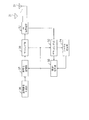
- FIG. 7 is a diagram showing an example of the block configuration of the user terminal 2.
- the user terminal 2 includes an antenna 31, an RF transmission / reception unit 32, a demapping unit 33, a channel estimation unit 34, a demodulation / decoding unit 35, a transmission signal generation unit 36, and encoding.
- the modulation unit 37 and the mapping unit 38 are included.
- the user terminal 3 also has a block configuration example similar to that of FIG. 7, and the description thereof is omitted.
- the RF transmitting and receiving unit 32 receives the DL signal transmitted by the wireless base station 1 and received by the one or more antennas 31.
- the RF transmission / reception unit 32 performs reception processing such as amplification and down conversion on the input DL signal.
- the RF transmission / reception unit 32 outputs the DL signal subjected to reception processing to the demapping unit 33.
- the demapping unit 33 separates (demaps) the DL control signal from the DL signal output from the RF transmission / reception unit 32. In addition, the demapping unit 33 generates a DL data signal addressed to the own machine from the DL signal output from the RF transmission / reception unit 32 based on the scheduling information (DL radio resource allocation information) output from the demodulation / decoding unit 35. Separate. Further, the demapping unit 33 separates the resource information of the UL control signal from the DL signal output from the RF transmission / reception unit 32.
- the channel estimation unit 34 receives the DL control signal demapped by the demapping unit 33.
- the channel estimation unit 34 estimates the channel state of DL based on the reference signal included in the input DL control signal.
- the channel estimation unit 34 outputs the estimated DL channel state to the demodulation and decoding unit 35.
- the demodulation and decoding unit 35 receives the DL channel state estimated by the channel estimation unit 34. Further, the demodulation / decoding unit 35 receives the DL control signal demapped by the demapping unit 33, the DL data signal, the resource, and the like. The demodulation and decoding unit 35 demodulates and decodes the resource information of the DL control signal, the DL data signal, and the UL control signal demapped by the demapping unit 33 based on the channel state estimated by the channel estimation unit 34. Do.
- the transmission signal generation unit 36 generates a UL signal including a UL data signal and a UL control signal.
- the UL signal output from the transmission signal generation unit 36 is input to the encoding / modulation unit 37. Further, the modulation and coding scheme (MCS) information of UL output from the demodulation and decoding unit 35 is input to the encoding and modulation unit 37.
- the coding / modulation unit 37 performs coding processing and modulation processing on the UL signal output from the transmission signal generation unit 36 based on the input UL MCS information.
- the coding / modulation unit 37 performs puncture processing for the UL data signal when the timing for transmitting the UL data signal to the radio base station 1 and the timing for the other user terminal 3 to transmit the UL control signal overlap with each other. Perform one of the coding rate adjustment processing.
- the puncture processing and the coding rate adjustment processing will be described below.
- the mapping unit 38 receives the UL signal that has been subjected to the encoding process and the modulation process by the encoding and modulation unit 37.
- the mapping unit 38 also receives the UL scheduling information demodulated and decoded by the demodulation and decoding unit 35.
- the mapping unit 38 maps the UL signal input from the encoding / modulation unit 37 to a predetermined radio resource (UL resource) based on the UL scheduling information input from the demodulation / decoding unit 35.
- the mapping unit 38 also receives (sets) resource information of the UL control signal that has been demodulated and decoded by the demodulation and decoding unit 35. When mapping the UL control signal to the radio resource, the mapping unit 38 maps the UL control signal to the radio resource based on the set resource information.
- the mapping unit 38 maps the UL data signal to a radio resource of a band to which the UL control signal is mapped. do not do.
- the user terminal 2 may transmit a UL signal to the radio base station 1 by DFT-s-OFDM.
- the DFT unit is inserted at the front stage of the mapping unit 38, and the IFFT unit is inserted at the rear stage of the mapping unit 38.
- the user terminal 2 may transmit a UL signal to the radio base station 1 by OFDM.
- the mapping unit 38 maps UL signals to continuous radio resources of one or more bands.
- the user terminal 2 may have a configuration unit (for example, a precoding unit or the like) for performing MIMO processing.
- FIG. 8 is a diagram for explaining an example of puncturing processing.
- the bandwidths W4a and W4b illustrated in FIG. 8 indicate the bandwidths allocated to the UL data signal of the user terminal 2.
- a bandwidth W4c indicated by a dotted line indicates a bandwidth allocated to the UL control signal.
- the user terminal 3 transmits a UL control signal using the bandwidth W4c.
- the bandwidths W4a and W4b correspond to, for example, 48 RBs of radio resources, and the bandwidth W4c corresponds to, for example, 2 RBs of radio resources.
- the encoding / modulation unit 37 generates a UL data signal with a size of 50 RB in accordance with the MCS information.
- the mapping unit 38 maps the UL data signal generated by the coding / modulation unit 37 to a radio resource. At this time, the mapping unit punctures 2 RBs allocated to the UL control signal from the UL data signal to be mapped. In the case of FIG. 8, the mapping unit 38 punctures RBs (2 RBs) at a position corresponding to the bandwidth W 4 c from the mapped 50 RBs UL data signal. That is, the mapping unit 38 maps UL data signals to radio resources so as to avoid a band in which other user terminals 3 map UL control signals.
- the user terminal 2 can suppress the interference between the UL data signal and the UL control signal of the user terminal 3, and can suppress the error rate decrease of the UL control signal and the error rate decrease of the UL data signal.
- the encoding / modulation unit 37 may puncture RBs (2 RBs) at positions corresponding to the bandwidth W 4 c from the generated 50 RBs UL data signals.
- FIG. 9 is a diagram for explaining an example of the adjustment of the coding rate.
- the same components as those in FIG. 8 are denoted by the same reference numerals.
- the bandwidths W4a and W4b correspond to, for example, 48 RBs of radio resources
- the bandwidth W4c corresponds to, for example, 2 RBs of radio resources.
- the encoding / modulation unit 37 When the UL data signal D3 is generated, the encoding / modulation unit 37 performs the code of the UL data signal D3 such that the UL data signal corresponding to the bandwidth W4c (2 RBs) is included in the UL data signal D3. Adjust the conversion rate. For example, the encoding / modulation unit 37 increases the coding rate of the UL data signal D3.
- the mapping unit 38 maps the UL data signal D3 whose coding rate has been adjusted, to a radio resource. At this time, the mapping unit 38 does not map the UL data signal D3 to the radio resource to which the UL control signal is mapped. That is, the mapping unit 38 maps UL data signals to radio resources so as to avoid a band in which other user terminals 3 map UL control signals.
- the user terminal 2 can suppress the interference between the UL data signal and the UL control signal of the user terminal 3, and can suppress the error rate decrease of the UL control signal and the error rate decrease of the UL data signal.
- the encoding / modulation unit 37 may switch between the puncturing process and the adjustment process of the coding rate in accordance with external control. Further, the coding / modulation unit 37 may have only one of the functions of puncturing processing and coding rate adjustment processing.
- FIG. 10 is a flowchart showing an example of the UL data signal transmission operation of the user terminal 2. It is assumed that the user terminal 2 has received resource information periodically notified from the radio base station 1.
- the control unit (not shown in FIG. 7) of the user terminal 2 determines whether there is a UL data signal to be transmitted to the radio base station 1 (step S11). If the control unit determines that there is no UL data signal to be transmitted to the radio base station 1 (“No” in S11), the processing of the flowchart is ended.
- control unit determines whether or not another user terminal 3 transmits a UL control signal (Ste S12). For example, the control unit determines whether another user terminal 3 transmits a UL control signal with reference to a predetermined bit of DCI.
- control unit determines that the other user terminal 3 does not transmit the UL control signal (“No” in step S12)
- the control unit shifts the process to step S14.
- the user terminal 2 When the process shifts to step S14, the user terminal 2 performs a normal transmission process (step S14).
- the encoding / modulation unit 37 encodes / modulates the UL data signal according to the MCS information
- the mapping unit 38 maps the UL data signal to a radio resource based on the UL scheduling information.
- the UL data signal mapped to the radio resource is transmitted to the radio base station 1 via the RF transmission / reception unit 32.
- step S12 when the control unit determines that the other user terminal 3 transmits the UL control signal in step S12 ("Yes" in step S12), the control unit shifts the process to step S13.
- the coding and modulation unit 37 codes and modulates a UL data signal.
- the mapping unit 38 maps the encoded / modulated UL data signal to a radio resource. At this time, the mapping unit 38 punctures the signal corresponding to the radio resource to which the UL control signal is assigned (step S13).
- the coding / modulation unit 37 increases the coding rate such that the UL data signal is mapped to the radio resource excluding the non-resources for the UL control signal. Then, the mapping unit 38 maps the UL data signal encoded and modulated by the encoding and modulation unit 37 on a radio resource. At this time, the mapping unit 38 does not map the UL data signal to the radio resource allocated to the UL control signal (step S13). The RF transmission / reception unit 32 transmits the UL data signal mapped to the radio resource to the radio base station 1 (step S13).
- the RF transmission / reception unit 32 of the user terminal 2 receives the resource information of the UL control signal transmitted by the other user terminal 3.
- the mapping unit 38 maps the UL data signal to a radio resource, and the RF transmission / reception unit 32 transmits the UL data signal to the radio base station 1 by radio. Then, when the DCI includes information indicating transmission of a UL control signal of another user terminal 3, the mapping unit 38 determines that the UL data signal has a band different from the band of the UL control signal indicated by the resource information. Map to the radio resource of By this process, the user terminal 2 can suppress the interference between the UL data signal and the UL control signal.
- the radio base station 1 notifies the user terminals 2 and 3 of the resource information of the UL control signal by RRC, MIB, SIB, RA response, Paging message or the like.
- the radio base station 1 notifies the resource information of the UL control signal to the user terminals 2 and 3 using the DL control information.
- the radio base station 1 transmits the UL data signal to the user terminal 2 and transmits the UL control signal to another user terminal 3. Assign discontinuous radio resources.
- the user terminal 2 receives discontinuous radio resource allocation information, it determines that another user terminal 3 transmits a UL control signal, and performs either puncturing processing or coding rate adjustment processing.
- UL data signal is transmitted to the radio base station 1.
- the user terminal 2 receives continuous radio resource allocation information, it determines that the other user terminal 3 does not transmit the UL control signal, and does not perform puncturing processing and coding rate adjustment processing, and thus UL A data signal is transmitted to the wireless base station 1.
- FIG. 11 is a diagram for explaining an operation example of the wireless communication system according to the second embodiment.
- the process S21 shown in FIG. 11 shows an example of the process of the radio base station 1 shown in FIG.
- Processing S22 shows an example of processing of the user terminals 2 and 3.
- the resource information (information of the band of the UL control signal) is individually set in each of the user terminals 2 and 3. That is, the resource information may be different for each of the user terminals 2 and 3 and may be the same. The resource information may be changed, for example, each time a DCI is sent.
- the user terminal 2 transmits a UL data signal and the user terminal 3 transmits a UL control signal will be described.
- the radio base station 1 When the user terminal 3 does not transmit a UL control signal, the radio base station 1 assigns a radio resource with a continuous band to the UL data signal of the user terminal 2 (S21). Also, when the user terminal 3 transmits a UL control signal, the radio base station 1 assigns a radio resource in which the band is not continuous to the UL data signal of the user terminal 2 (S21). Radio resource allocation information may be notified, for example, by DCI.
- the user terminal 2 transmits a UL data signal to the radio base station 1 and the user terminal 3 transmits a UL control signal to the radio base station 1 will be described.
- the user terminal 2 determines that the other user terminal 3 does not transmit the UL control signal when allocation of radio resources of the UL data signal notified by DCI is continuous, and performs puncturing processing or coding rate adjustment processing Do not do (S22).
- the user terminal 2 determines that another user terminal 3 transmits a UL control signal, and performs puncturing processing or adjustment of the coding rate A process is performed (S22).
- FIG. 12 is a diagram showing an example of bands assigned to the UL data signal and the UL control signal.
- a bandwidth W5a illustrated in FIG. 12 indicates the bandwidth of the user terminal 2 assigned to the UL data signal.
- Information of the bandwidth W5a is notified from the radio base station 1 to the user terminal 2 by, for example, DCI.
- the bandwidth W5b indicates the bandwidth of the user terminal 3 assigned to the UL control signal.
- the information of the bandwidth W5b is notified from the radio base station 1 to the user terminal 3 by DCI, for example.
- the allocation of the radio resource of the UL data signal of the user terminal 2 is discontinuous as shown by the bandwidth W5a It becomes.
- the UL data signal of the user terminal 2 is discontinuously allocated to radio resources so as not to interfere with the UL control signal of the user terminal 3.
- the encoding / modulation unit 37 When the UL data signal of the user terminal 2 is discontinuously allocated to the radio resource, the encoding / modulation unit 37 performs either the puncturing process or the encoding rate adjustment process as described in FIG. 8 and FIG. 9. Do one or the other. Then, the mapping unit 38 maps the UL data signal to a radio resource of a band different from the band indicated by the resource information.
- resource information is individually set in the user terminals 2 and 3 and is included in DCI including uplink scheduling information.
- the scheduling information included in the DCI includes information indicating that the radio resource of the UL data signal is discontinuous
- the mapping unit 38 separates the UL data signal from the band indicated by the resource information. Map to band radio resources. By this process, the user terminal 2 can suppress the interference between the UL data signal and the UL control signal. Also, UL control information can be allocated to radio resources more flexibly.
- the user terminal 2 transmitting the UL data signal is assigned the transmission timing of the UL data signal to the other user terminal 3 even when the other user terminal 3 does not transmit the UL control signal.
- the UL data signal is mapped to a radio resource different from the radio resource indicated by the resource information.
- FIG. 13 is a diagram for explaining an operation example of the wireless communication system according to the third embodiment. An example of the radio resource of the user terminal 2 is shown in FIG.
- Radio resources A1 to A3 shown in FIG. 13 indicate radio resources to which UL control signals can be allocated. That is, when transmitting the UL control signal, the user terminal 3 allocates and transmits the UL control signal to the radio resources A1 to A3. The user terminal 3 does not transmit the UL control signal if there is no UL control signal to be transmitted to the radio base station 1 at the timing of the radio resources A1 to A3.
- the radio base station 1 transmits UL control signal resource information to the user terminals 2 and 3 by RRC, S1 connection setup, MIB, SIB, RA response, Paging message, etc., for example. Notify Therefore, the user terminal 2 can recognize the radio resources A1 to A3 of the UL control signal transmitted by the other user terminal 3. Since the resource information is common to the user terminals 2 and 3, the user terminal 2 also transmits the UL control signal using the radio resources A1 to A3. Further, when the resource information is not notified, the user terminals 2 and 3 may use resource information determined in advance according to the specifications, or may use resource information set last.
- the mapping unit 38 of the user terminal 2 transmits the UL data signal at the transmission timing even when the other user terminal 3 does not transmit the UL control signal at the transmission timing of the radio resources A1 to A3 allocated by the resource information.
- the UL data signal is mapped to a radio resource of a band different from the band indicated by the resource information.
- the other user terminal 3 transmits the UL control signal in the radio resource A2 and does not transmit the UL control signal in the radio resources A1 and A3.
- the UL control signal is not transmitted at transmission timing T1 at which the transmission timing overlaps with the radio resource A1, but the mapping unit 38 allocates UL data signals to radio resources other than the radio resource A1.
- the mapping unit 38 allocates UL data signals to radio resources other than the radio resource A2.
- the UL control signal is not transmitted, but the mapping unit 38 allocates the UL data signal to radio resources other than the radio resource A3.
- the coding / modulation unit 37 performs either puncturing processing or coding rate adjustment processing at transmission timings T1 to T3. By this process, the user terminal 2 can suppress the decrease in throughput of the UL data signal at the transmission timings T1 to T3.
- the coding / modulation unit 37 does not perform puncturing processing or coding rate adjustment processing at timings other than the transmission timings T1 to T3.
- the mapping unit 38 of the user terminal 2 is a transmission timing in which the transmission timing of the UL data signal is assigned to the other user terminal 3 even when the other user terminal 3 does not transmit the UL control signal. And the UL data signal is mapped to a radio resource different from the radio resource indicated by the resource information. By this process, the user terminal 2 can suppress the interference between the UL data signal and the UL control signal.
- the resource information is notified to the user terminals 2 and 3 by RRC, MIB, SIB or the like, but may be notified to the user terminals 2 and 3 by DCI or the like.
- the radio resources of the UL data signal are reduced by the bandwidth of the UL control signal when the UL control signal is transmitted.
- the user terminal 2 transmitting the UL data signal raises the power spectral density of the radio resource to which the UL data signal is allocated.
- the RF transmission / reception unit 32 of the user terminal 2 determines, for example, the transmission power of the UL data signal based on the following equation (1).
- P PUSCH is the transmission power of the RF transmission / reception unit 32.
- M PUSCH is the number of RBs allocated to UL data signals transmitted by radio.
- P O — PUSCH is the target received power when the propagation loss is zero.
- ⁇ is a weighting factor of fractional TPC (TPC: Transmission Power Control).
- PL is a measurement value of propagation loss.
- ⁇ TF (TF (i)) is an offset at timing TF (i) depending on MCS (modulation and coding scheme).
- f (i) is a correction value at timing i by TPC or Extended TPC.
- the number of RBs allocated to the UL data signal is 50 RBs. If puncturing was 2 RB (UL control signal to the RB number assigned 2 RB), RF transceiver unit 32, the M PUSCH if 50 RB, it is possible to increase the power spectral density of the UL data signal.
- the RF transmission / reception unit 32 may correct the transmission power of the UL data signal represented by equation (1) based on the number of RBs allocated to the UL data signal and the number of RBs allocated to the UL control signal. .
- FIG. 14 is a table showing an example of the relationship between the number of RBs assigned to the UL data signal, the number of RBs assigned to the UL control signal, and the correction value.
- the number of RBs allocated to the UL data signal is 25, and the number of RBs allocated to the UL control signal is 2.
- the correction value X is 0.3 according to the table shown in FIG.
- Equation (2) has a correction term X with respect to equation (1).
- the correction term X can be obtained from the table shown in FIG.
- the table shown in FIG. 14 may be stored in a storage unit (not shown in FIG. 7) of the user terminal 2 or notified by S1 connection setting, MIB, SIB, RA response, Paging message, etc. May be
- the RF transmission / reception unit 32 can perform power control in consideration of an Adjacent Channel Leakage Ratio (ACLR) by introducing the correction term X.
- ACLR Adjacent Channel Leakage Ratio
- the RF transmission / reception unit 32 uses the number of RBs of the UL data signal before the RB is reduced to Determine transmit power. Through this process, the user terminal 2 improves the throughput.
- the RF transmission / reception unit 32 corrects the determined transmission power based on the number of RBs allocated to the UL data signal and the number of RBs allocated to the UL control signal. By this processing, the RF transmission and reception unit 32 can perform power control in consideration of ACLR.
- the above transmission power control can be applied to the first to fourth embodiments.
- each functional block (components) are realized by any combination of hardware and / or software.
- the implementation means of each functional block is not particularly limited. That is, each functional block may be realized by one physically and / or logically coupled device, or directly and / or indirectly two or more physically and / or logically separated devices. It may be connected by (for example, wired and / or wireless) and realized by the plurality of devices.
- each device of the wireless communication system in one embodiment of the present invention may function as a computer that performs the processing of the present invention.
- FIG. 15 is a diagram showing an example of a hardware configuration of a radio base station and a user terminal according to an embodiment of the present invention.
- Each of the above-described devices may be physically configured as a computer device including a processor 1001, a memory 1002, a storage 1003, a communication device 1004, an input device 1005, an output device 1006, a bus 1007, and the like.
- the term “device” can be read as a circuit, a device, a unit, or the like.
- the hardware configuration of the radio base station and the user terminal may be configured to include one or more of the devices illustrated in the figure, or may be configured without some of the devices.
- processor 1001 may be implemented by one or more chips.
- Each function in each device causes the processor 1001 to perform an operation by reading predetermined software (program) on hardware such as the processor 1001 and the memory 1002, and the communication by the communication device 1004 or the memory 1002 and the storage 1003. This is realized by controlling the reading and / or writing of data in
- the processor 1001 operates, for example, an operating system to control the entire computer.
- the processor 1001 may be configured by a central processing unit (CPU: Central Processing Unit) including an interface with a peripheral device, a control device, an arithmetic device, a register, and the like.
- CPU Central Processing Unit
- the above block example may be realized by the processor 1001.
- the processor 1001 reads a program (program code), a software module or data from the storage 1003 and / or the communication device 1004 to the memory 1002, and executes various processing according to these.
- a program a program that causes a computer to execute at least a part of the operations described in the above embodiments is used.
- at least a part of functional blocks constituting each device may be realized by a control program stored in the memory 1002 and operated by the processor 1001, and may be realized similarly for other functional blocks.
- the various processes described above have been described to be executed by one processor 1001, but may be executed simultaneously or sequentially by two or more processors 1001.
- the processor 1001 may be implemented by one or more chips.
- the program may be transmitted from the network via a telecommunication line.
- the memory 1002 is a computer readable recording medium, and includes, for example, at least one of a ROM (Read Only Memory), an EPROM (Erasable Programmable ROM), an EEPROM (Electrically Erasable Programmable ROM), and a RAM (Random Access Memory). It may be done.
- the memory 1002 may be called a register, a cache, a main memory (main storage device) or the like.
- the memory 1002 can store a program (program code), a software module, and the like that can be executed to implement each device according to an embodiment of the present invention.
- the storage 1003 is a computer readable recording medium, and for example, an optical disc such as a CD-ROM (Compact Disc ROM), a hard disc drive, a flexible disc, a magneto-optical disc (eg, a compact disc, a digital versatile disc, a Blu-ray A (registered trademark) disk, a smart card, a flash memory (for example, a card, a stick, a key drive), a floppy (registered trademark) disk, a magnetic strip, and the like may be used.
- the storage 1003 may be called an auxiliary storage device.
- the above-mentioned storage medium may be, for example, a database including the memory 1002 and / or the storage 1003, a server or any other suitable medium.
- the communication device 1004 is hardware (transmission / reception device) for performing communication between computers via a wired and / or wireless network, and is also called, for example, a network device, a network controller, a network card, a communication module, or the like.
- the input device 1005 is an input device (for example, a keyboard, a mouse, a microphone, a switch, a button, a sensor, and the like) that receives an input from the outside.
- the output device 1006 is an output device (for example, a display, a speaker, an LED lamp, etc.) that performs output to the outside.
- the input device 1005 and the output device 1006 may be integrated (for example, a touch panel).
- each device such as the processor 1001 and the memory 1002 is connected by a bus 1007 for communicating information.
- the bus 1007 may be configured by a single bus or may be configured by different buses among the devices.
- each device includes hardware such as a microprocessor, a digital signal processor (DSP), an application specific integrated circuit (ASIC), a programmable logic device (PLD), and a field programmable gate array (FPGA).
- DSP digital signal processor
- ASIC application specific integrated circuit
- PLD programmable logic device
- FPGA field programmable gate array
- notification of information is not limited to the aspect / embodiment described herein, and may be performed by other methods.
- notification of information may be physical layer signaling (for example, Downlink Control Information (DCI), Uplink Control Information (UCI)), upper layer signaling (for example, Radio Resource Control (RRC) signaling, Medium Access Control (MAC) signaling, It may be implemented by broadcast information (MIB (Master Information Block), SIB (System Information Block)), other signals, or a combination thereof.
- RRC signaling may be referred to as an RRC message, and may be, for example, an RRC connection setup (RRC Connection Setup) message, an RRC connection reconfiguration (RRC Connection Reconfiguration) message, or the like.
- Each aspect / embodiment described in the present specification is LTE (Long Term Evolution), LTE-A (LTE-Advanced), SUPER 3G, IMT-Advanced, 4G, 5G, FRA (Future Radio Access), W-CDMA (Registered trademark), GSM (registered trademark), CDMA2000, UMB (Ultra Mobile Broadband), IEEE 802.11 (Wi-Fi), IEEE 802.16 (WiMAX), IEEE 802.20, UWB (Ultra-Wide Band),
- the present invention may be applied to a system utilizing Bluetooth (registered trademark), other appropriate systems, and / or an advanced next-generation system based on these.
- the specific operation supposed to be performed by the base station (radio base station) in this specification may be performed by the upper node in some cases.
- the various operations performed for communication with the terminals may be the base station and / or other network nodes other than the base station (eg, It is obvious that this may be performed by, but not limited to, MME (Mobility Management Entity) or S-GW (Serving Gateway).
- MME Mobility Management Entity
- S-GW Serving Gateway
- Information, signals, etc. may be output from the upper layer (or lower layer) to the lower layer (or upper layer). Input and output may be performed via a plurality of network nodes.
- the input / output information or the like may be stored in a specific place (for example, a memory) or may be managed by a management table. Information to be input or output may be overwritten, updated or added. The output information etc. may be deleted. The input information or the like may be transmitted to another device.
- the determination may be performed by a value (0 or 1) represented by one bit, may be performed by a boolean value (Boolean: true or false), or may be compared with a numerical value (for example, a predetermined value). Comparison with the value).
- Software may be called software, firmware, middleware, microcode, hardware description language, or any other name, and may be instructions, instruction sets, codes, code segments, program codes, programs, subprograms, software modules. Should be interpreted broadly to mean applications, software applications, software packages, routines, subroutines, objects, executables, threads of execution, procedures, functions, etc.
- software, instructions, etc. may be sent and received via a transmission medium.
- software may use a wireline technology such as coaxial cable, fiber optic cable, twisted pair and digital subscriber line (DSL) and / or a website, server or other using wireless technology such as infrared, radio and microwave When transmitted from a remote source, these wired and / or wireless technologies are included within the definition of transmission medium.
- wireline technology such as coaxial cable, fiber optic cable, twisted pair and digital subscriber line (DSL) and / or a website, server or other using wireless technology such as infrared, radio and microwave
- Information, signal The information, signals, etc. described herein may be represented using any of a variety of different techniques.
- data, instructions, commands, information, signals, bits, symbols, chips etc may be voltage, current, electromagnetic waves, magnetic fields or particles, optical fields or photons, or any of these May be represented by a combination of
- the channels and / or symbols may be signals.
- the signal may be a message.
- the component carrier (CC) may be called a carrier frequency, a cell or the like.
- radio resources may be indexed.
- a base station can accommodate one or more (e.g., three) cells (also called sectors). If the base station accommodates multiple cells, the entire coverage area of the base station can be divided into multiple smaller areas, each smaller area being a base station subsystem (eg, a small base station RRH for indoor use: Remote Communication service can also be provided by Radio Head.
- the terms "cell” or “sector” refer to a part or all of the coverage area of a base station and / or a base station subsystem serving communication services in this coverage.
- base station “eNB”, “cell” and “sector” may be used interchangeably herein.
- a base station may be called in terms of a fixed station (Node station), NodeB, eNodeB (eNB), access point (access point), femtocell, small cell, and the like.
- the user terminal may be a mobile station, a subscriber station, a mobile unit, a subscriber unit, a wireless unit, a remote unit, a mobile device, a wireless device, a wireless communication device, a remote communication device, a mobile subscriber station, an access terminal, a mobile terminal by a person skilled in the art It may also be called a terminal, a wireless terminal, a remote terminal, a handset, a user agent, a mobile client, a client, a UE (User Equipment), or some other suitable term.
- determining may encompass a wide variety of operations.
- “Judgment”, “decision” are, for example, judging, calculating, calculating, processing, processing, deriving, investigating, looking up (for example, a table) (Searching in a database or another data structure), ascertaining may be regarded as “decision”, “decision”, etc.
- “determination” and “determination” are receiving (e.g. receiving information), transmitting (e.g. transmitting information), input (input), output (output), access (accessing) (for example, accessing data in a memory) may be regarded as “judged” or “decided”.
- connection means any direct or indirect connection or coupling between two or more elements, It can include the presence of one or more intermediate elements between two elements that are “connected” or “coupled”.
- the coupling or connection between elements may be physical, logical or a combination thereof.
- the two elements are by using one or more wires, cables and / or printed electrical connections, and radio frequency as some non-limiting and non-exclusive examples. It can be considered “connected” or “coupled” to one another by using electromagnetic energy such as electromagnetic energy having wavelengths in the region, microwave region and light (both visible and invisible) regions.
- the reference signal may be abbreviated as RS (Reference Signal), and may be called a pilot (Pilot) according to the applied standard.
- the correction RS may be called TRS (Tracking RS), PC-RS (Phase Compensation RS), PTRS (Phase Tracking RS), or Additional RS.
- the demodulation RS and the correction RS may be different names corresponding to each other.
- the demodulation RS and the correction RS may be defined by the same name (for example, the demodulation RS).
- the phrase “based on” does not mean “based only on,” unless expressly stated otherwise. In other words, the phrase “based on” means both “based only on” and “based at least on.”
- a radio frame may be comprised of one or more frames in the time domain.
- One or more frames in the time domain may be referred to as subframes, time units, and so on.
- a subframe may be further comprised of one or more slots in the time domain.
- the slot may be further configured with one or more symbols (such as orthogonal frequency division multiplexing (OFDM) symbols, single carrier-frequency division multiple access (SC-FDMA) symbols, etc.) in the time domain.
- OFDM orthogonal frequency division multiplexing
- SC-FDMA single carrier-frequency division multiple access
- a radio frame, a subframe, a slot, and a symbol all represent time units in transmitting a signal.
- a radio frame, a subframe, a slot, and a symbol may be another name corresponding to each.
- the base station performs scheduling to assign radio resources (frequency bandwidth usable in each mobile station, transmission power, etc.) to each mobile station.
- the minimum time unit of scheduling may be called a TTI (Transmission Time Interval).
- one subframe may be called a TTI
- a plurality of consecutive subframes may be called a TTI
- one slot may be called a TTI
- a resource unit is a resource allocation unit in time domain and frequency domain, and may include one or more consecutive subcarriers in frequency domain.
- the time domain of a resource unit may include one or more symbols, and may be one slot, one subframe, or one TTI long.
- One TTI and one subframe may be configured of one or more resource units, respectively.
- resource units may be referred to as resource blocks (RBs), physical resource blocks (PRBs: physical RBs), PRB pairs, RB pairs, scheduling units, frequency units, and subbands.
- a resource unit may be configured of one or more REs.
- 1 RE may be a resource of a unit smaller than the resource unit serving as a resource allocation unit (for example, the smallest resource unit), and is not limited to the name of RE.
- the above-described radio frame structure is merely an example, and the number of subframes included in the radio frame, the number of slots included in the subframe, the number of symbols and resource blocks included in the slots, and the sub The number of carriers can vary.
- notification of predetermined information is not limited to what is explicitly performed, but is performed by implicit (for example, not notifying of the predetermined information) It is also good.
- One aspect of the present invention is useful for a mobile communication system.
Landscapes
- Engineering & Computer Science (AREA)
- Computer Networks & Wireless Communication (AREA)
- Signal Processing (AREA)
- Mobile Radio Communication Systems (AREA)
Abstract
異なるユーザ端末が送信する上りデータ信号と上り制御信号との干渉を抑制する。無線基地局と無線通信を行うユーザ端末であって、他のユーザ端末が送信する上り制御信号の無線リソースを示すリソース情報を受信する受信部と、上りデータ信号を、リソース情報が示す無線リソースとは別の無線リソースにマッピングするマッピング部と、無線リソースにマッピングされた上りデータ信号を送信する送信部と、を有する。
Description
本発明は、次世代移動通信システムにおけるユーザ端末および無線通信方法に関する。
UMTS(Universal Mobile Telecommunication System)ネットワークにおいて、更なる高速データレート、低遅延などを目的としてロングタームエボリューション(LTE:Long Term Evolution)が仕様化された(非特許文献1)。また、LTEからの更なる広帯域化および高速化を目的として、LTEの後継システムも検討されている。LTEの後継システムには、例えば、LTE-A(LTE-Advanced)、FRA(Future Radio Access)、5G(5th generation mobile communication system)、5G+(5G plus)、New-RAT(Radio Access Technology)などと呼ばれるものがある。
しかしながら、現在5Gでは、あるユーザ端末が送信する上りデータ信号と、他のユーザ端末が送信する上り制御信号とが混在した環境における送信方法やリソース割り当てについては規定されていない。そのため、同一のリソースで、あるユーザ端末が、上りデータ信号を送信し、他のユーザ端末が上り制御信号送信すると、信号の干渉を生じる恐れがある。
そこで本発明は、異なるユーザ端末が送信する上りデータ信号と上り制御信号との干渉を抑制する技術を提供することを目的とする。
本発明のユーザ端末は、無線基地局と無線通信を行うユーザ端末であって、他のユーザ端末が送信する上り制御信号の無線リソースを示すリソース情報を受信する受信部と、上りデータ信号を、前記リソース情報が示す無線リソースとは別の無線リソースにマッピングするマッピング部と、無線リソースにマッピングされた前記上りデータ信号を送信する送信部と、を有する。
本発明によれば、異なるユーザ端末が送信する上りデータ信号と上り制御信号との干渉を抑制できる。
以下、本発明の実施の形態を、図面を参照して説明する。
(第1の実施の形態)
図1は、第1の実施の形態に係る無線通信システムの構成例を示した図である。図1に示すように、無線通信システムは、無線基地局1と、ユーザ端末2,3と、を有している。
図1は、第1の実施の形態に係る無線通信システムの構成例を示した図である。図1に示すように、無線通信システムは、無線基地局1と、ユーザ端末2,3と、を有している。
無線基地局1は、New-RATを適用した無線基地局である。無線基地局1は、例えば、数十から数百本のアンテナを有し、高周波帯(例えば、5GHz以上の周波数帯)において、ユーザ端末2,3と無線通信を行う。無線基地局1は、複数のアンテナを用いて、信号の振幅および位相を制御し、指向性を有するビームを形成して、ユーザ端末2,3と信号の送受信を行う。ユーザ端末2,3は、例えば、携帯電話、スマートフォン、またはタブレット端末等である。
無線基地局1は、コアネットワーク(図示せず)に接続されている。コアネットワークは、例えば、MME(Mobility Management Entity)、S-GW(Serving Gateway)、またはP-GW(Pakcet Data network Gateway)等の上位装置を含んでもよい。
なお、無線基地局1は、C-RAN(Centralized Radio Access Network)または高度化C-RANに対応するように、例えば、ユーザ端末2,3と無線通信を行う張出局と、張出局を制御するBBU(BaseBand processing Unit)とに分離されていてもよい。また、図1には、2台のユーザ端末2,3しか示していないが、本実施の形態では3台以上存在してもよい。
図2は、ユーザ端末2,3のUL(Up Link)の帯域幅の例を説明する図である。図2に示す帯域幅W1aは、ユーザ端末2のULにおける送信可能な帯域幅を示している。帯域幅W1bは、ユーザ端末3のULにおける送信可能な帯域幅を示している。
5GのULでは、高速大容量化のため、広帯域でデータを送信することが検討されている。また、5GのULでは、通信可能な帯域幅は、ユーザ端末2,3ごとに異なっていることが想定される。例えば、帯域幅W1a,W1bに示すように、ユーザ端末2,3のULにおける送信可能な帯域幅は、異なっていることが想定される。
図3は、UL制御信号とULデータ信号との干渉の例を説明する図である。図3に示す帯域幅W2aは、ユーザ端末2のULデータ信号に割り当てられた帯域幅の例を示している。ULデータ信号は、例えば、PUSCH(Physical Uplink Shared Channel)であってもよい。
帯域幅W2bは、ユーザ端末3のUL制御信号に割り当てられた帯域幅の例を示している。UL制御信号は、例えば、PUCCH(Physical Uplink Control Channel)であってもよい。
なお、点線で示す帯域幅W1bは、図2で説明したユーザ端末3のULにおける送信可能な帯域幅を示している。
DFT-s-OFDM(Discrete Fourier Transform-Spread Orthogonal Frequency Division Multiplexing)等のシングルキャリアベースでは、ULデータ信号およびUL制御信号は、例えば、帯域幅W2a,W2bに示すように、連続した帯域に割り当てられる。OFDMの場合も、リソース割り当ての制御を簡易化するため、低PAPR(Peak to Average Power Ration)を図るため、ULデータ信号およびUL制御信号は、1つの連続した帯域または複数の連続した帯域に割り当てられる。
図2で説明したように、5GのULにおける通信可能な帯域幅は、ユーザ端末2,3ごとに異なっていることが想定される。また、ULデータ信号は、高速大容量化のため、広帯域で送信されることが想定される。そのため、ユーザ端末2が送信するULデータ信号と、ユーザ端末3が送信するUL制御信号とが干渉(衝突)する可能性がある。
例えば、図3の例では、ユーザ端末2のULデータ信号に割り当てられた帯域幅W2aは、ユーザ端末3の送信可能な帯域幅W1bより広い。そして、ユーザ端末3のUL制御信号は、帯域幅W1b内の帯域幅W2bを用いて送信される。このため、ユーザ端末2が送信するULデータ信号の帯域幅W2aは、ユーザ端末3のUL制御信号の送信用に割り当てられた帯域幅W2bと重なる場合がある。従って、ユーザ端末2が送信するULデータ信号と、ユーザ端末3が送信するUL制御信号とが干渉する可能性がある。
なお、LTEでは、UL制御信号の送信に、システム帯域の両端の帯域が使用される。例えば、LTEでは、UL制御信号は、図3に示す帯域幅W1bの両端の帯域で送信される。帯域幅W1bの両端の帯域を用いても、その帯域は、ユーザ端末2のULデータ信号の帯域幅W2aと重なる。従って、ユーザ端末3のUL制御信号は、ユーザ端末2のULデータ信号と干渉する可能性がある。
そこで、ユーザ端末2は、他のユーザ端末3が送信するUL制御信号の帯域(無線リソース)には、ULデータ信号を割り当てないようにする。
図4は、ユーザ端末2のULデータ信号の割り当ての例を説明する図である。図4に示す帯域幅W3aは、ユーザ端末2のULデータ信号に割り当てられた帯域幅の例を示している。帯域幅W3bは、ユーザ端末3のUL制御信号に割り当てられた帯域幅の例を示している。
帯域幅W3aに示すように、ULデータ信号を送信するユーザ端末2は、帯域幅W3bに示すユーザ端末3のUL制御信号の帯域幅と重なる帯域に、ULデータ信号を割り当てない。従って、ユーザ端末2のULデータ信号と、ユーザ端末3のUL制御信号は、干渉が抑制される。
図5は、無線通信システムの動作例を説明する図である。図5に示す処理S1は、図1に示した無線基地局1の処理例を示している。処理S2は、ユーザ端末2,3の処理例を示している。
無線基地局1は、UL制御信号のリソース情報を、周期的にユーザ端末2,3に通知する(S1a)。
リソース情報には、ユーザ端末2,3がUL制御信号を送信するための帯域の情報が含まれている。例えば、リソース情報には、図4に示した帯域幅W3bの情報が含まれてもよい。
リソース情報(UL制御信号の帯域の情報)は、ユーザ端末2,3において共通(同じ)である。ユーザ端末2,3は、UL制御信号を送信するとき、受信したリソース情報に含まれる帯域に、UL制御信号を割り当て、無線基地局1に送信する。すなわち、ユーザ端末2,3は、無線基地局1から通知された帯域に、UL制御信号を割り当て、無線基地局1に送信する。
無線基地局1は、例えば、数十msecの間隔で、UL制御信号のリソース情報をユーザ端末2,3に通知する。無線基地局1は、UL制御信号のリソース情報に含める帯域を変更してもよい。
無線基地局1は、DL制御情報を用いて、他のユーザ端末がUL制御信号を送信するか否かを示す情報をユーザ端末2,3に通知する(S1b)。
DL制御情報は、例えば、DCI(Downlink Control Information)であってもよい。例えば、ユーザ端末3が、UL制御信号を送信する場合であって、ユーザ端末2がULデータ信号を送信する場合、ユーザ端末2に送信されるDCIには、他のユーザ端末3がUL制御信号を送信することを示す情報が含まれる。また、例えば、ユーザ端末2が、UL制御信号を送信する場合であって、ユーザ端末3がULデータ信号を送信する場合、ユーザ端末3に送信されるDCIには、他のユーザ端末2がUL制御信号を送信することを示す情報が含まれる。なお、他のユーザ端末がUL制御信号を送信するか否かを示す情報は、例えば、DCIの所定のビット(例えば、1ビット)を用いて、ユーザ端末2,3に通知されてもよい。
ユーザ端末2,3の処理例について説明する。ユーザ端末2,3は、無線基地局1から通知されるリソース情報を受信し、受信したリソース情報に含まれるUL制御信号の帯域を、例えば、後述するマッピング部(例えば、図7を参照)に設定する(S2a)。
マッピング部は、UL制御信号を送信するとき、設定された帯域に、UL制御信号をマッピングする。例えば、無線基地局1から通知されたリソース情報に、図4に示した帯域幅W3bの帯域情報が含まれていた場合、ユーザ端末2,3のマッピング部は、図4に示した帯域幅W3bにUL制御信号をマッピングする。
ここで、ユーザ端末2は、ULデータ信号を無線基地局1に送信し、ユーザ端末2は、UL制御信号を無線基地局1に送信する場合について説明する。
ユーザ端末2は、無線基地局1から送信されたDL制御情報から、他のユーザ端末3が、UL制御信号を送信するか否かを判定する(S2b)。例えば、ユーザ端末2は、DCIの所定の1ビットを参照し、他のユーザ端末3が、UL制御信号を送信するか否かを判定する。
ユーザ端末2は、他のユーザ端末3が、UL制御信号を送信する場合、無線基地局1から通知されたリソース情報(UL制御信号の帯域)に、ULデータ信号を割り当てない(S2c)。例えば、ユーザ端末2は、図4の帯域幅W3aに示すように、UL制御信号が割り当てられる帯域幅W3bと重なる帯域には、ULデータ信号を割り当てない。
以上の処理によって、ユーザ端末2,3は、ULデータ信号と、他のユーザ端末が送信するUL制御信号との干渉を抑制し、無線基地局1に送信できる。
なお、上記では、ユーザ端末2が、ULデータ信号を無線基地局1に送信し、ユーザ端末2が、UL制御信号を無線基地局1に送信する場合について説明したが、逆も同様である。すなわち、ユーザ端末3が、ULデータ信号を無線基地局1に送信し、ユーザ端末2が、UL制御信号を無線基地局1に送信する場合も、上記の処理と同様となる。
図6は、無線基地局1のブロック構成例を示した図である。図6に示すように、無線基地局1は、制御部(スケジューラ)21と、送信信号生成部22と、符号化・変調部23と、マッピング部24と、RF送信部25と、アンテナ26と、を有している。
制御部21は、DLデータ信号およびDL制御信号等のスケジューリングを行う。DLデータ信号は、例えば、PDSCH(Physical Downlink Shared Channel)であってもよい。DL制御信号は、例えば、PDCCH(Physical Downlink Control Channel)であってもよい。
また、制御部21は、ユーザ端末2,3に通知する、UL制御信号のリソース情報をスケジューリングする。リソース情報は、例えば、RRC(Radio Resource Control)、S1接続設定、MIB(Master Information Block)、SIB(System Information Block)、RA response、Pagingメッセージ等によって、ユーザ端末2,3に通知されてもよい。また、リソース情報が通知されない場合には、ユーザ端末2,3は、予め仕様で決められたリソース情報を用いてもよく、最後に設定したリソース情報を用いてもよい。
送信信号生成部22は、DL信号(DLデータ信号、DL制御信号、およびUL制御信号のリソース情報等を含む)を生成する。例えば、DL制御信号には、制御部21が生成したスケジューリング情報を含むDCI等が含まれる。送信信号生成部22は、生成したDL信号を、符号化・変調部23に出力する。
符号化・変調部23は、DL信号に対して、符号化処理および変調処理を行う。符号化・変調部23は、符号化・変調処理したDL信号をマッピング部24に出力する。
マッピング部24は、符号化・変調部23から出力されるDL信号を、制御部21のスケジューリングに基づいて、無線リソースにマッピングする。
RF送信部25は、マッピング部24から出力されるDL信号に対して、アップコンバートおよび増幅等の送信処理を行い、複数のアンテナ26からユーザ端末2に送信する。
なお、図6には図示していないが、無線基地局1は、ユーザ端末2,3から送信されたULデータ信号およびUL制御信号等を処理する受信処理部を有している。例えば、無線基地局1は、デマッピング部、チャネル推定部、および復調・復号部等を有している。
また、図6では、信号波形を生成するための構成部(例えば、IFFT処理部、CP付加部、CP除去部、FFT処理部等)の記載を省略している。また、図6では、MIMO処理を実施するための構成部(例えば、プリコーディング部等)の記載を省略している。
図7は、ユーザ端末2のブロック構成例を示した図である。図7に示すように、ユーザ端末2は、アンテナ31と、RF送受信部32と、デマッピング部33と、チャネル推定部34と、復調・復号部35と、送信信号生成部36と、符号化・変調部37と、マッピング部38と、を有している。なお、ユーザ端末3も図7と同様のブロック構成例を有し、その説明を省略する。
RF送受信部32には、1つもしくは複数のアンテナ31によって受信された、無線基地局1が送信したDL信号が入力される。RF送受信部32は、入力されたDL信号に対して、増幅およびダウンコンバート等の受信処理を行う。RF送受信部32は、受信処理したDL信号を、デマッピング部33に出力する。
デマッピング部33は、RF送受信部32から出力されるDL信号から、DL制御信号を分離(デマッピング)する。また、デマッピング部33は、復調・復号部35から出力されるスケジューリング情報(DLの無線リソース割当情報)に基づいて、RF送受信部32から出力されるDL信号から、自機宛てのDLデータ信号を分離する。また、デマッピング部33は、RF送受信部32から出力されるDL信号から、UL制御信号のリソース情報を分離する。
チャネル推定部34には、デマッピング部33によってデマッピングされたDL制御信号が入力される。チャネル推定部34は、入力されたDL制御信号に含まれる参照信号に基づいて、DLのチャネル状態を推定する。チャネル推定部34は、推定したDLのチャネル状態を、復調・復号部35に出力する。
復調・復号部35には、チャネル推定部34で推定されたDLのチャネル状態が入力される。また、復調・復号部35には、デマッピング部33でデマッピングされたDL制御信号、DLデータ信号、およびリソース等が入力される。復調・復号部35は、チャネル推定部34によって推定されたチャネル状態に基づいて、デマッピング部33によってデマッピングされたDL制御信号、DLデータ信号、およびUL制御信号のリソース情報の復調および復号を行う。
送信信号生成部36は、ULデータ信号およびUL制御信号を含むUL信号を生成する。
符号化・変調部37には、送信信号生成部36から出力されるUL信号が入力される。また、符号化・変調部37には、復調・復号部35から出力されるULのMCS(Modulation and Coding Scheme)情報が入力される。符号化・変調部37は、入力されたULのMCS情報に基づいて、送信信号生成部36から出力されるUL信号に対し、符号化処理および変調処理を行う。
また、符号化・変調部37は、ULデータ信号を無線基地局1に送信するタイミングと、他のユーザ端末3がUL制御信号を送るタイミングとが重なる場合、ULデータ信号に対し、パンクチャ処理および符号化率の調整処理のいずれか一方を行う。パンクチャ処理および符号化率の調整処理は、以下で説明する。
マッピング部38には、符号化・変調部37で符号化処理および変調処理されたUL信号が入力される。また、マッピング部38には、復調・復号部35で復調および復号されたULのスケジューリング情報が入力される。マッピング部38は、符号化・変調部37から入力されるUL信号を、復調・復号部35から入力されるULのスケジューリング情報に基づいて、所定の無線リソース(ULリソース)にマッピングする。
また、マッピング部38は、復調・復号部35で復調および復号された、UL制御信号のリソース情報が入力(設定)される。マッピング部38は、UL制御信号を無線リソースにマッピングするとき、設定されたリソース情報に基づいて、UL制御信号を無線リソースにマッピングする。
また、マッピング部38は、DCIに他のユーザ端末3がUL制御信号を送信することを示す情報が含まれている場合、UL制御信号がマッピングされる帯域の無線リソースに、ULデータ信号をマッピングしない。
なお、ユーザ端末2は、DFT-s-OFDMによって、UL信号を無線基地局1に送信してもよい。この場合、マッピング部38の前段には、DFT部が挿入され、マッピング部38の後段には、IFFT部が挿入される。また、ユーザ端末2は、OFDMによって、UL信号を無線基地局1に送信してもよい。この場合、マッピング部38は、連続した1以上の帯域の無線リソースにUL信号をマッピングする。また、ユーザ端末2は、MIMO処理を実施するための構成部(例えば、プリコーディング部等)を有してもよい。
図8は、パンクチャ処理の例を説明する図である。図8に示す帯域幅W4a,W4bは、ユーザ端末2の、ULデータ信号に割り当てられる帯域を示している。
点線で示す帯域幅W4cは、UL制御信号に割り当てられる帯域を示している。ユーザ端末3は、帯域幅W4cを用いて、UL制御信号を送信する。
帯域幅W4a,W4bは、例えば、無線リソースの48RBに相当し、帯域幅W4cは、例えば、無線リソースの2RBに相当するとする。
この場合、符号化・変調部37は、50RB分の大きさとなるULデータ信号を、MCS情報に従って生成する。
マッピング部38は、符号化・変調部37で生成されたULデータ信号を、無線リソースにマッピングする。そのとき、マッピング部38は、マッピングするULデータ信号から、UL制御信号に割り当てられている2RB分をパンクチャする。図8の場合、マッピング部38は、マッピングした50RB分のULデータ信号から、帯域幅W4cに対応する位置のRB(2RB分)をパンクチャする。すなわち、マッピング部38は、他のユーザ端末3がUL制御信号をマッピングする帯域を避けるように、ULデータ信号を無線リソースにマッピングする。
この処理によって、ユーザ端末2は、ULデータ信号と、ユーザ端末3のUL制御信号との干渉を抑制できるとともに、UL制御信号の誤り率低下およびULデータ信号の誤り率低下を抑制できる。なお、符号化・変調部37が、生成した50RB分のULデータ信号から帯域幅W4cに対応する位置のRB(2RB分)をパンクチャしてもよい。
図9は、符号化率の調整の例を説明する図である。図9において、図8と同じものには同じ符号が付してある。図8と同様に、帯域幅W4a,W4bは、例えば、無線リソースの48RBに相当し、帯域幅W4cは、例えば、無線リソースの2RBに相当するとする。
符号化・変調部37は、帯域幅W4a,W4bに対応する48RB分の大きさとなるULデータ信号を生成する。例えば、符号化・変調部37は、図9に示すように、48RB分のULデータ信号D3(D1のサイズxRB+D2のサイズyRB=D3のサイズ48RB)を生成する。
符号化・変調部37は、ULデータ信号D3を生成するとき、帯域幅W4cに対応する分(2RB分)のULデータ信号が、ULデータ信号D3に含まれるように、ULデータ信号D3の符号化率を調整する。例えば、符号化・変調部37は、ULデータ信号D3の符号化率を上げる。
マッピング部38は、符号化率が調整されたULデータ信号D3を、無線リソースにマッピングする。このとき、マッピング部38は、ULデータ信号D3を、UL制御信号がマッピングされる無線リソースにマッピングしない。すなわち、マッピング部38は、他のユーザ端末3がUL制御信号をマッピングする帯域を避けるように、ULデータ信号を無線リソースにマッピングする。
この処理によって、ユーザ端末2は、ULデータ信号と、ユーザ端末3のUL制御信号との干渉を抑制できるとともに、UL制御信号の誤り率低下およびULデータ信号の誤り率低下を抑制できる。
なお、符号化・変調部37は、外部からの制御に応じて、パンクチャ処理および符号化率の調整処理を切替えるようにしてもよい。また、符号化・変調部37は、パンクチャ処理および符号化率の調整処理のいずれかの機能のみを有してもよい。
図10は、ユーザ端末2のULデータ信号の送信動作例を示したフローチャートである。ユーザ端末2は、無線基地局1から周期的に通知されるリソース情報を受信しているとする。
ユーザ端末2の制御部(図7には図示せず)は、無線基地局1に送信するULデータ信号があるか否かを判定する(ステップS11)。制御部は、無線基地局1に送信するULデータ信号がないと判定した場合(S11の「No」)、当該フローチャートの処理を終了する。
一方、制御部は、無線基地局1に送信するULデータ信号があると判定した場合(S11の「Yes」)、他のユーザ端末3が、UL制御信号を送信するか否かを判定する(ステップS12)。例えば、制御部は、DCIの所定のビットを参照して、他のユーザ端末3が、UL制御信号を送信するか否かを判定する。
制御部は、他のユーザ端末3が、UL制御信号を送信しないと判定した場合(ステップS12の「No」)、ステップS14に処理を移行する。
ユーザ端末2は、ステップS14に処理が移行すると、通常の送信処理を行う(ステップS14)。例えば、符号化・変調部37は、MCS情報に従って、ULデータ信号を符号化・変調処理し、マッピング部38は、ULのスケジューリング情報に基づいて、ULデータ信号を、無線リソースにマッピングする。無線リソースにマッピングされたULデータ信号は、RF送受信部32を介して、無線基地局1に送信される。
一方、制御部は、ステップS12にて、他のユーザ端末3が、UL制御信号を送信すると判定した場合(ステップS12の「Yes」)、ステップS13に処理を移行する。
パンクチャ処理を行う場合、符号化・変調部37は、ULデータ信号を符号化・変調処理する。マッピング部38は、符号化・変調処理されたULデータ信号を無線リソースにマッピングする。このとき、マッピング部38は、UL制御信号が割り当てられている無線リソースに対応する信号をパンクチャする(ステップS13)。
一方、符号化率の調整処理を行う場合、符号化・変調部37は、UL制御信号分の無縁リソースを除いた無線リソースに、ULデータ信号がマッピングされるように、符号化率を上げる。そして、マッピング部38は、符号化・変調部37で符号化・変調処理されたULデータ信号を無線リソースにマッピングする。このとき、マッピング部38は、UL制御信号に割り当てられている無線リソースに、ULデータ信号をマッピングしない(ステップS13)。RF送受信部32は、無線リソースにマッピングされたULデータ信号を無線基地局1に送信する(ステップS13)。
以上説明したように、ユーザ端末2のRF送受信部32は、他のユーザ端末3が送信するUL制御信号のリソース情報を受信する。マッピング部38は、ULデータ信号を無線リソースにマッピングし、RF送受信部32は、ULデータ信号を無線基地局1に無線送信する。そして、マッピング部38は、DCIに、他のユーザ端末3のUL制御信号の送信を示す情報が含まれている場合、ULデータ信号を、リソース情報が示すUL制御信号の帯域とは別の帯域の無線リソースにマッピングする。この処理によって、ユーザ端末2は、ULデータ信号とUL制御信号との干渉を抑制できる。
(第2の実施の形態)
第1の実施の形態では、無線基地局1は、RRC、MIB、SIB、RA response、Pagingメッセージ等によって、UL制御信号のリソース情報をユーザ端末2,3に通知した。第2の実施の形態では、無線基地局1は、UL制御信号のリソース情報を、DL制御情報を用いてユーザ端末2,3に通知する。
第1の実施の形態では、無線基地局1は、RRC、MIB、SIB、RA response、Pagingメッセージ等によって、UL制御信号のリソース情報をユーザ端末2,3に通知した。第2の実施の形態では、無線基地局1は、UL制御信号のリソース情報を、DL制御情報を用いてユーザ端末2,3に通知する。
また、第2の実施の形態では、無線基地局1は、ユーザ端末2がULデータ信号を送信する場合であって、他のユーザ端末3がUL制御信号を送信する場合、ユーザ端末2に対し、不連続な無線リソースの割り当てを行う。ユーザ端末2は、不連続な無線リソースの割り当て情報を受信した場合、他のユーザ端末3が、UL制御信号を送信すると判定し、パンクチャ処理および符号化率の調整処理のいずれか一方を行って、ULデータ信号を無線基地局1に送信する。一方、ユーザ端末2は、連続した無線リソースの割り当て情報を受信した場合、他のユーザ端末3が、UL制御信号を送信しないと判定し、パンクチャ処理および符号化率の調整処理を行わず、ULデータ信号を無線基地局1に送信する。以下では、第1の実施の形態と異なる点について説明する。
図11は、第2の実施の形態に係る無線通信システムの動作例を説明する図である。図11に示す処理S21は、図1に示した無線基地局1の処理例を示している。処理S22は、ユーザ端末2,3の処理例を示している。
リソース情報(UL制御信号の帯域の情報)は、各ユーザ端末2,3において個別に設定される。つまり、リソース情報は、ユーザ端末2,3のそれぞれで異なる場合もあり、また、同じ場合もある。リソース情報は、例えば、DCIが送信されるたび変更されてもよい。
以下では、ユーザ端末2は、ULデータ信号を送信し、ユーザ端末3は、UL制御信号を送信する場合について説明する。
無線基地局1は、ユーザ端末3がUL制御信号を送信しない場合、ユーザ端末2のULデータ信号に、帯域が連続した無線リソースを割り当てる(S21)。また、無線基地局1は、ユーザ端末3がUL制御信号を送信する場合、ユーザ端末2のULデータ信号に、帯域が連続しない無線リソースを割り当てる(S21)。無線リソースの割り当て情報は、例えば、DCIで通知されてもよい。
ここで、ユーザ端末2は、ULデータ信号を無線基地局1に送信し、ユーザ端末3は、UL制御信号を無線基地局1に送信する場合について説明する。
ユーザ端末2は、DCIで通知されたULデータ信号の無線リソースの割り当てが連続している場合、他のユーザ端末3がUL制御信号を送信しないと判定し、パンクチャ処理または符号化率の調整処理を行わない(S22)。一方、ユーザ端末2は、DCIで通知されたULデータ信号の無線リソースの割り当てが不連続である場合、他のユーザ端末3がUL制御信号を送信すると判定し、パンクチャ処理または符号化率の調整処理を行う(S22)。
図12は、ULデータ信号およびUL制御信号に割り当てられた帯域例を示した図である。図12に示す帯域幅W5aは、ユーザ端末2の、ULデータ信号に割り当てられた帯域を示している。帯域幅W5aの情報は、例えば、DCIによって、無線基地局1からユーザ端末2に通知される。
帯域幅W5bは、ユーザ端末3の、UL制御信号に割り当てられた帯域を示している。帯域幅W5bの情報は、例えば、DCIによって、無線基地局1からユーザ端末3に通知される。
ユーザ端末3のUL制御信号が、帯域幅W5bに示すように、無線リソースに割り当てられている場合、ユーザ端末2のULデータ信号の無線リソースの割り当ては、帯域幅W5aに示すように、不連続となる。例えば、ユーザ端末2のULデータ信号は、ユーザ端末3のUL制御信号と干渉しないように、不連続に無線リソースに割り当てられる。
ユーザ端末2のULデータ信号が、不連続に無線リソースに割り当てられた場合、符号化・変調部37は、図8および図9で説明したように、パンクチャ処理または符号化率の調整処理のいずれか一方を行う。そして、マッピング部38は、ULデータ信号を、リソース情報が示す帯域とは別の帯域の無線リソースにマッピングする。
以上説明したように、リソース情報は、ユーザ端末2,3において個別に設定され、上りのスケジューリング情報を含むDCIに含められる。マッピング部38は、DCIに含まれるスケジューリング情報に、ULデータ信号の無線リソースが不連続であることを示す情報が含まれている場合に、ULデータ信号を、リソース情報が示す帯域とは別の帯域の無線リソースにマッピングする。この処理によって、ユーザ端末2は、ULデータ信号とUL制御信号との干渉を抑制できる。また、UL制御情報は、よりフレキシブルに無線リソースに割り当てられることができる。
(第3の実施の形態)
第3の実施の形態では、ULデータ信号を送信するユーザ端末2は、他のユーザ端末3が、UL制御信号を送信しない場合でも、ULデータ信号の送信タイミングが、他のユーザ端末3に割り当てられた送信タイミングと重なる場合、ULデータ信号を、リソース情報が示す無線リソースとは別の無線リソースにマッピングする。以下では、第1の実施の形態と異なる点について説明する。
第3の実施の形態では、ULデータ信号を送信するユーザ端末2は、他のユーザ端末3が、UL制御信号を送信しない場合でも、ULデータ信号の送信タイミングが、他のユーザ端末3に割り当てられた送信タイミングと重なる場合、ULデータ信号を、リソース情報が示す無線リソースとは別の無線リソースにマッピングする。以下では、第1の実施の形態と異なる点について説明する。
図13は、第3の実施の形態に係る無線通信システムの動作例を説明する図である。図13には、ユーザ端末2の無線リソースの例が示してある。
図13に示す無線リソースA1~A3は、UL制御信号の割り当て可能な無線リソースを示している。すなわち、ユーザ端末3は、UL制御信号を送信するとき、無線リソースA1~A3にUL制御信号を割り当てて送信する。なお、ユーザ端末3は、無線リソースA1~A3のタイミングで、無線基地局1に送信するUL制御信号が無ければ、UL制御信号を送信しない。
無線基地局1は、第1の実施の形態でも説明したように、例えば、RRC、S1接続設定、MIB、SIB、RA response、Pagingメッセージ等によって、UL制御信号のリソース情報をユーザ端末2,3に通知する。従って、ユーザ端末2は、他のユーザ端末3が送信するUL制御信号の無線リソースA1~A3を認識できる。なお、リソース情報は、ユーザ端末2,3において共通であるので、ユーザ端末2も、UL制御信号を送信するときは、無線リソースA1~A3を用いて送信する。また、リソース情報が通知されない場合には、ユーザ端末2,3は、予め仕様で決められたリソース情報を用いてもよく、最後に設定したリソース情報を用いてもよい。
ユーザ端末2のマッピング部38は、他のユーザ端末3が、リソース情報で割り当てられた無線リソースA1~A3の送信タイミングで、UL制御信号を送信しない場合でも、ULデータ信号の送信タイミングが、無線リソースA1~A3の送信タイミングと重なる場合、ULデータ信号を、リソース情報が示す帯域とは別の帯域の無線リソースにマッピングする。
例えば、他のユーザ端末3は、無線リソースA2において、UL制御信号を送信し、無線リソースA1,A3において、UL制御信号を送信しないとする。この場合、無線リソースA1と送信タイミングが重なる送信タイミングT1では、UL制御信号は送信されないが、マッピング部38は、無線リソースA1以外の無線リソースにULデータ信号を割り当てる。また、無線リソースA2と送信タイミングが重なる送信タイミングT2では、マッピング部38は、無線リソースA2以外の無線リソースにULデータ信号を割り当てる。また、無線リソースA3と送信タイミングが重なる送信タイミングT3では、UL制御信号は送信されないが、マッピング部38は、無線リソースA3以外の無線リソースにULデータ信号を割り当てる。
符号化・変調部37は、送信タイミングT1~T3において、パンクチャ処理または符号化率の調整処理のいずれか一方を行う。この処理によって、ユーザ端末2は、送信タイミングT1~T3での、ULデータ信号のスループットの低下を抑制できる。
なお、符号化・変調部37は、送信タイミングT1~T3以外のタイミングでは、パンクチャ処理または符号化率の調整処理を行わない。
以上説明したように、ユーザ端末2のマッピング部38は、他のユーザ端末3が、UL制御信号を送信しない場合でも、ULデータ信号の送信タイミングが、他のユーザ端末3に割り当てられた送信タイミングと重なる場合、ULデータ信号を、リソース情報が示す無線リソースとは別の無線リソースにマッピングする。この処理によって、ユーザ端末2は、ULデータ信号とUL制御信号との干渉を抑制できる。
なお、上記では、リソース情報は、RRC、MIB、またはSIB等によって、ユーザ端末2,3に通知されるとしたが、DCI等によって、ユーザ端末2,3に通知されてもよい。
(第4の実施の形態)
ULデータ信号の無線リソースは、UL制御信号が送信されるとき、UL制御信号の帯域分、少なくなる。第5の実施の形態では、ULデータ信号を送信するユーザ端末2は、ULデータ信号が割り当てられた無線リソースの電力スペクトル密度を上げる。
ULデータ信号の無線リソースは、UL制御信号が送信されるとき、UL制御信号の帯域分、少なくなる。第5の実施の形態では、ULデータ信号を送信するユーザ端末2は、ULデータ信号が割り当てられた無線リソースの電力スペクトル密度を上げる。
ユーザ端末2のRF送受信部32は、例えば、ULデータ信号の送信電力を、次の式(1)に基づいて決定する。

ここで、PPUSCHは、RF送受信部32の送信電力である。MPUSCHは、無線送信されるULデータ信号に割り当てられるRB数である。PO_PUSCHは、伝搬ロスを0とした場合の目標受信電力である。αは、フラクショナルTPC(TPC:Transmission Power Control)の重み係数である。PLは、伝搬ロスの測定値である。ΔTF(TF(i))は、MCS(変調・符号化方式)に依存するタイミングTF(i)におけるオフセットである。f(i)は、TPCまたはExtended TPCによるタイミングiにおける補正値である。
ULデータ信号に割り当てられたRB数を50RBとする。パンクチャが2RB(UL制御信号に割り当てられたRB数が2RB)であった場合、RF送受信部32は、MPUSCHを50RBとすれば、ULデータ信号の電力スペクトル密度を上げることができる。
RF送受信部32は、ULデータ信号に割り当てられたRB数と、UL制御信号に割り当てられたRB数とに基づいて、式(1)で示されるULデータ信号の送信電力を補正してもよい。
図14は、ULデータ信号に割り当てられたRB数、UL制御信号に割り当てられたRB数、および補正値の関係例を示したテーブルである。例えば、ULデータ信号に割り当てられたRB数を25、UL制御信号に割り当てられたRB数を2とする。この場合、補正値Xは、図14に示すテーブルより、0.3となる。
補正値Xを含む式を次の式(2)に示す。

式(2)は、式(1)に対し、補正項Xを有している。補正項Xは、図14に示したテーブルから求まる。なお、図14に示すテーブルは、ユーザ端末2が有する記憶部(図7には図示せず)に記憶されてもよいし、S1接続設定、MIB、SIB、RA response、Pagingメッセージ等によって通知されてもよい。RF送受信部32は、補正項Xの導入よって、ACLR(Adjacent Channel Leakage Ratio)を考慮した電力制御を行うことができる。
以上説明したように、RF送受信部32は、ULデータ信号のRBが、UL制御信号のRB分減らされても、RBが減らされる前のULデータ信号のRB数を用いて、ULデータ信号の送信電力を決定する。この処理によって、ユーザ端末2は、スループットが向上する。
また、RF送受信部32は、ULデータ信号に割り当てられたRB数と、UL制御信号に割り当てられたRB数とに基づいて、決定する送信電力を補正する。この処理によって、RF送受信部32は、ACLRを考慮した電力制御を行うことができる。
なお、上記の送信電力制御は、第1の実施の形態~第4の実施の形態に適用できる。
以上、各実施の形態について説明した。
(ハードウェア構成)
上記実施の形態の説明に用いたブロック図は、機能単位のブロックを示している。これらの機能ブロック(構成部)は、ハードウェア及び/又はソフトウェアの任意の組み合わせによって実現される。また、各機能ブロックの実現手段は特に限定されない。すなわち、各機能ブロックは、物理的及び/又は論理的に結合した1つの装置により実現されてもよいし、物理的及び/又は論理的に分離した2つ以上の装置を直接的及び/又は間接的に(例えば、有線及び/又は無線)で接続し、これら複数の装置により実現されてもよい。
上記実施の形態の説明に用いたブロック図は、機能単位のブロックを示している。これらの機能ブロック(構成部)は、ハードウェア及び/又はソフトウェアの任意の組み合わせによって実現される。また、各機能ブロックの実現手段は特に限定されない。すなわち、各機能ブロックは、物理的及び/又は論理的に結合した1つの装置により実現されてもよいし、物理的及び/又は論理的に分離した2つ以上の装置を直接的及び/又は間接的に(例えば、有線及び/又は無線)で接続し、これら複数の装置により実現されてもよい。
例えば、本発明の一実施の形態における無線通信システムの各装置は、本発明の処理を行うコンピュータとして機能してもよい。図15は、本発明の一実施形態に係る無線基地局及びユーザ端末のハードウェア構成の一例を示す図である。上述の各装置は、物理的には、プロセッサ1001、メモリ1002、ストレージ1003、通信装置1004、入力装置1005、出力装置1006、バス1007などを含むコンピュータ装置として構成されてもよい。
なお、以下の説明では、「装置」という文言は、回路、デバイス、ユニットなどに読み替えることができる。無線基地局及びユーザ端末のハードウェア構成は、図に示した各装置を1つ又は複数含むように構成されてもよいし、一部の装置を含まずに構成されてもよい。
例えば、プロセッサ1001は1つだけ図示されているが、複数のプロセッサがあってもよい。また、処理は、1のプロセッサで実行されてもよいし、処理が同時に、逐次に、又はその他の手法で、一以上のプロセッサで実行されてもよい。なお、プロセッサ1001は、一以上のチップで実装されてもよい。
各装置における各機能は、プロセッサ1001、メモリ1002などのハードウェア上に所定のソフトウェア(プログラム)を読み込ませることで、プロセッサ1001が演算を行い、通信装置1004による通信、又は、メモリ1002及びストレージ1003におけるデータの読み出し及び/又は書き込みを制御することで実現される。
プロセッサ1001は、例えば、オペレーティングシステムを動作させてコンピュータ全体を制御する。プロセッサ1001は、周辺装置とのインターフェース、制御装置、演算装置、レジスタなどを含む中央処理装置(CPU:Central Processing Unit)で構成されてもよい。例えば、上述のブロック例、プロセッサ1001で実現されてもよい。
また、プロセッサ1001は、プログラム(プログラムコード)、ソフトウェアモジュール又はデータを、ストレージ1003及び/又は通信装置1004からメモリ1002に読み出し、これらに従って各種の処理を実行する。プログラムとしては、上述の実施の形態で説明した動作の少なくとも一部をコンピュータに実行させるプログラムが用いられる。例えば、各装置を構成する少なくとも一部の機能ブロックは、メモリ1002に格納され、プロセッサ1001で動作する制御プログラムによって実現されてもよく、他の機能ブロックについても同様に実現されてもよい。上述の各種処理は、1つのプロセッサ1001で実行される旨を説明してきたが、2以上のプロセッサ1001により同時又は逐次に実行されてもよい。プロセッサ1001は、1以上のチップで実装されてもよい。なお、プログラムは、電気通信回線を介してネットワークから送信されてもよい。
メモリ1002は、コンピュータ読み取り可能な記録媒体であり、例えば、ROM(Read Only Memory)、EPROM(Erasable Programmable ROM)、EEPROM(Electrically Erasable Programmable ROM)、RAM(Random Access Memory)などの少なくとも1つで構成されてもよい。メモリ1002は、レジスタ、キャッシュ、メインメモリ(主記憶装置)などと呼ばれてもよい。メモリ1002は、本発明の一実施形態に係る各装置を実施するために実行可能なプログラム(プログラムコード)、ソフトウェアモジュールなどを保存することができる。
ストレージ1003は、コンピュータ読み取り可能な記録媒体であり、例えば、CD-ROM(Compact Disc ROM)などの光ディスク、ハードディスクドライブ、フレキシブルディスク、光磁気ディスク(例えば、コンパクトディスク、デジタル多用途ディスク、Blu-ray(登録商標)ディスク)、スマートカード、フラッシュメモリ(例えば、カード、スティック、キードライブ)、フロッピー(登録商標)ディスク、磁気ストリップなどの少なくとも1つで構成されてもよい。ストレージ1003は、補助記憶装置と呼ばれてもよい。上述の記憶媒体は、例えば、メモリ1002及び/又はストレージ1003を含むデータベース、サーバその他の適切な媒体であってもよい。
通信装置1004は、有線及び/又は無線ネットワークを介してコンピュータ間の通信を行うためのハードウェア(送受信デバイス)であり、例えばネットワークデバイス、ネットワークコントローラ、ネットワークカード、通信モジュールなどともいう。
入力装置1005は、外部からの入力を受け付ける入力デバイス(例えば、キーボード、マウス、マイクロフォン、スイッチ、ボタン、センサなど)である。出力装置1006は、外部への出力を実施する出力デバイス(例えば、ディスプレイ、スピーカー、LEDランプなど)である。なお、入力装置1005及び出力装置1006は、一体となった構成(例えば、タッチパネル)であってもよい。
また、プロセッサ1001及びメモリ1002などの各装置は、情報を通信するためのバス1007で接続される。バス1007は、単一のバスで構成されてもよいし、装置間で異なるバスで構成されてもよい。
また、各装置は、マイクロプロセッサ、デジタル信号プロセッサ(DSP:Digital Signal Processor)、ASIC(Application Specific Integrated Circuit)、PLD(Programmable Logic Device)、FPGA(Field Programmable Gate Array)などのハードウェアを含んで構成されてもよく、当該ハードウェアにより、各機能ブロックの一部又は全てが実現されてもよい。例えば、プロセッサ1001は、これらのハードウェアの少なくとも1つで実装されてもよい。
(情報の通知、シグナリング)
また、情報の通知は、本明細書で説明した態様/実施形態に限られず、他の方法で行われてもよい。例えば、情報の通知は、物理レイヤシグナリング(例えば、DCI(Downlink Control Information)、UCI(Uplink Control Information))、上位レイヤシグナリング(例えば、RRC(Radio Resource Control)シグナリング、MAC(Medium Access Control)シグナリング、報知情報(MIB(Master Information Block)、SIB(System Information Block)))、その他の信号又はこれらの組み合わせによって実施されてもよい。また、RRCシグナリングは、RRCメッセージと呼ばれてもよく、例えば、RRC接続セットアップ(RRC Connection Setup)メッセージ、RRC接続再構成(RRC Connection Reconfiguration)メッセージなどであってもよい。
また、情報の通知は、本明細書で説明した態様/実施形態に限られず、他の方法で行われてもよい。例えば、情報の通知は、物理レイヤシグナリング(例えば、DCI(Downlink Control Information)、UCI(Uplink Control Information))、上位レイヤシグナリング(例えば、RRC(Radio Resource Control)シグナリング、MAC(Medium Access Control)シグナリング、報知情報(MIB(Master Information Block)、SIB(System Information Block)))、その他の信号又はこれらの組み合わせによって実施されてもよい。また、RRCシグナリングは、RRCメッセージと呼ばれてもよく、例えば、RRC接続セットアップ(RRC Connection Setup)メッセージ、RRC接続再構成(RRC Connection Reconfiguration)メッセージなどであってもよい。
(適応システム)
本明細書で説明した各態様/実施形態は、LTE(Long Term Evolution)、LTE-A(LTE-Advanced)、SUPER 3G、IMT-Advanced、4G、5G、FRA(Future Radio Access)、W-CDMA(登録商標)、GSM(登録商標)、CDMA2000、UMB(Ultra Mobile Broadband)、IEEE 802.11(Wi-Fi)、IEEE 802.16(WiMAX)、IEEE 802.20、UWB(Ultra-WideBand)、Bluetooth(登録商標)、その他の適切なシステムを利用するシステム及び/又はこれらに基づいて拡張された次世代システムに適用されてもよい。
本明細書で説明した各態様/実施形態は、LTE(Long Term Evolution)、LTE-A(LTE-Advanced)、SUPER 3G、IMT-Advanced、4G、5G、FRA(Future Radio Access)、W-CDMA(登録商標)、GSM(登録商標)、CDMA2000、UMB(Ultra Mobile Broadband)、IEEE 802.11(Wi-Fi)、IEEE 802.16(WiMAX)、IEEE 802.20、UWB(Ultra-WideBand)、Bluetooth(登録商標)、その他の適切なシステムを利用するシステム及び/又はこれらに基づいて拡張された次世代システムに適用されてもよい。
(処理手順等)
本明細書で説明した各態様/実施形態の処理手順、シーケンス、フローチャートなどは、矛盾の無い限り、順序を入れ替えてもよい。例えば、本明細書で説明した方法については、例示的な順序で様々なステップの要素を提示しており、提示した特定の順序に限定されない。
本明細書で説明した各態様/実施形態の処理手順、シーケンス、フローチャートなどは、矛盾の無い限り、順序を入れ替えてもよい。例えば、本明細書で説明した方法については、例示的な順序で様々なステップの要素を提示しており、提示した特定の順序に限定されない。
(基地局の操作)
本明細書において基地局(無線基地局)によって行われるとした特定動作は、場合によってはその上位ノード(upper node)によって行われることもある。基地局を有する1つまたは複数のネットワークノード(network nodes)からなるネットワークにおいて、端末との通信のために行われる様々な動作は、基地局および/または基地局以外の他のネットワークノード(例えば、MME(Mobility Management Entity)またはS-GW(Serving Gateway)などが考えられるが、これらに限られない)によって行われ得ることは明らかである。上記において基地局以外の他のネットワークノードが1つである場合を例示したが、複数の他のネットワークノードの組み合わせ(例えば、MMEおよびS-GW)であってもよい。
本明細書において基地局(無線基地局)によって行われるとした特定動作は、場合によってはその上位ノード(upper node)によって行われることもある。基地局を有する1つまたは複数のネットワークノード(network nodes)からなるネットワークにおいて、端末との通信のために行われる様々な動作は、基地局および/または基地局以外の他のネットワークノード(例えば、MME(Mobility Management Entity)またはS-GW(Serving Gateway)などが考えられるが、これらに限られない)によって行われ得ることは明らかである。上記において基地局以外の他のネットワークノードが1つである場合を例示したが、複数の他のネットワークノードの組み合わせ(例えば、MMEおよびS-GW)であってもよい。
(入出力の方向)
情報及び信号等は、上位レイヤ(または下位レイヤ)から下位レイヤ(または上位レイヤ)に出力され得る。複数のネットワークノードを介して入出力されてもよい。
情報及び信号等は、上位レイヤ(または下位レイヤ)から下位レイヤ(または上位レイヤ)に出力され得る。複数のネットワークノードを介して入出力されてもよい。
(入出力された情報等の扱い)
入出力された情報等は特定の場所(例えば、メモリ)に保存されてもよいし、管理テーブルで管理してもよい。入出力される情報等は、上書き、更新、または追記され得る。出力された情報等は削除されてもよい。入力された情報等は他の装置に送信されてもよい。
入出力された情報等は特定の場所(例えば、メモリ)に保存されてもよいし、管理テーブルで管理してもよい。入出力される情報等は、上書き、更新、または追記され得る。出力された情報等は削除されてもよい。入力された情報等は他の装置に送信されてもよい。
(判定方法)
判定は、1ビットで表される値(0か1か)によって行われてもよいし、真偽値(Boolean:trueまたはfalse)によって行われてもよいし、数値の比較(例えば、所定の値との比較)によって行われてもよい。
判定は、1ビットで表される値(0か1か)によって行われてもよいし、真偽値(Boolean:trueまたはfalse)によって行われてもよいし、数値の比較(例えば、所定の値との比較)によって行われてもよい。
(ソフトウェア)
ソフトウェアは、ソフトウェア、ファームウェア、ミドルウェア、マイクロコード、ハードウェア記述言語と呼ばれるか、他の名称で呼ばれるかを問わず、命令、命令セット、コード、コードセグメント、プログラムコード、プログラム、サブプログラム、ソフトウェアモジュール、アプリケーション、ソフトウェアアプリケーション、ソフトウェアパッケージ、ルーチン、サブルーチン、オブジェクト、実行可能ファイル、実行スレッド、手順、機能などを意味するよう広く解釈されるべきである。
ソフトウェアは、ソフトウェア、ファームウェア、ミドルウェア、マイクロコード、ハードウェア記述言語と呼ばれるか、他の名称で呼ばれるかを問わず、命令、命令セット、コード、コードセグメント、プログラムコード、プログラム、サブプログラム、ソフトウェアモジュール、アプリケーション、ソフトウェアアプリケーション、ソフトウェアパッケージ、ルーチン、サブルーチン、オブジェクト、実行可能ファイル、実行スレッド、手順、機能などを意味するよう広く解釈されるべきである。
また、ソフトウェア、命令などは、伝送媒体を介して送受信されてもよい。例えば、ソフトウェアが、同軸ケーブル、光ファイバケーブル、ツイストペア及びデジタル加入者回線(DSL)などの有線技術及び/又は赤外線、無線及びマイクロ波などの無線技術を使用してウェブサイト、サーバ、又は他のリモートソースから送信される場合、これらの有線技術及び/又は無線技術は、伝送媒体の定義内に含まれる。
(情報、信号)
本明細書で説明した情報、信号などは、様々な異なる技術のいずれかを使用して表されてもよい。例えば、上記の説明全体に渡って言及され得るデータ、命令、コマンド、情報、信号、ビット、シンボル、チップなどは、電圧、電流、電磁波、磁界若しくは磁性粒子、光場若しくは光子、又はこれらの任意の組み合わせによって表されてもよい。
本明細書で説明した情報、信号などは、様々な異なる技術のいずれかを使用して表されてもよい。例えば、上記の説明全体に渡って言及され得るデータ、命令、コマンド、情報、信号、ビット、シンボル、チップなどは、電圧、電流、電磁波、磁界若しくは磁性粒子、光場若しくは光子、又はこれらの任意の組み合わせによって表されてもよい。
なお、本明細書で説明した用語及び/又は本明細書の理解に必要な用語については、同一の又は類似する意味を有する用語と置き換えてもよい。例えば、チャネル及び/又はシンボルは信号(シグナル)であってもよい。また、信号はメッセージであってもよい。また、コンポーネントキャリア(CC)は、キャリア周波数、セルなどと呼ばれてもよい。
(「システム」、「ネットワーク」)
本明細書で使用する「システム」および「ネットワーク」という用語は、互換的に使用される。
本明細書で使用する「システム」および「ネットワーク」という用語は、互換的に使用される。
(パラメータ、チャネルの名称)
また、本明細書で説明した情報、パラメータなどは、絶対値で表されてもよいし、所定の値からの相対値で表されてもよいし、対応する別の情報で表されてもよい。例えば、無線リソースはインデックスで指示されるものであってもよい。
また、本明細書で説明した情報、パラメータなどは、絶対値で表されてもよいし、所定の値からの相対値で表されてもよいし、対応する別の情報で表されてもよい。例えば、無線リソースはインデックスで指示されるものであってもよい。
上述したパラメータに使用する名称はいかなる点においても限定的なものではない。さらに、これらのパラメータを使用する数式等は、本明細書で明示的に開示したものと異なる場合もある。様々なチャネル(例えば、PUCCH、PDCCHなど)及び情報要素(例えば、TPCなど)は、あらゆる好適な名称によって識別できるので、これらの様々なチャネル及び情報要素に割り当てている様々な名称は、いかなる点においても限定的なものではない。
(基地局)
基地局(無線基地局)は、1つまたは複数(例えば、3つ)の(セクタとも呼ばれる)セルを収容することができる。基地局が複数のセルを収容する場合、基地局のカバレッジエリア全体は複数のより小さいエリアに区分でき、各々のより小さいエリアは、基地局サブシステム(例えば、屋内用の小型基地局RRH:Remote Radio Head)によって通信サービスを提供することもできる。「セル」または「セクタ」という用語は、このカバレッジにおいて通信サービスを行う基地局、および/または基地局サブシステムのカバレッジエリアの一部または全体を指す。さらに、「基地局」、「eNB」、「セル」、および「セクタ」という用語は、本明細書では互換的に使用され得る。基地局は、固定局(fixed station)、NodeB、eNodeB(eNB)、アクセスポイント(access point)、フェムトセル、スモールセルなどの用語で呼ばれる場合もある。
基地局(無線基地局)は、1つまたは複数(例えば、3つ)の(セクタとも呼ばれる)セルを収容することができる。基地局が複数のセルを収容する場合、基地局のカバレッジエリア全体は複数のより小さいエリアに区分でき、各々のより小さいエリアは、基地局サブシステム(例えば、屋内用の小型基地局RRH:Remote Radio Head)によって通信サービスを提供することもできる。「セル」または「セクタ」という用語は、このカバレッジにおいて通信サービスを行う基地局、および/または基地局サブシステムのカバレッジエリアの一部または全体を指す。さらに、「基地局」、「eNB」、「セル」、および「セクタ」という用語は、本明細書では互換的に使用され得る。基地局は、固定局(fixed station)、NodeB、eNodeB(eNB)、アクセスポイント(access point)、フェムトセル、スモールセルなどの用語で呼ばれる場合もある。
(端末)
ユーザ端末は、当業者によって、移動局、加入者局、モバイルユニット、加入者ユニット、ワイヤレスユニット、リモートユニット、モバイルデバイス、ワイヤレスデバイス、ワイヤレス通信デバイス、リモートデバイス、モバイル加入者局、アクセス端末、モバイル端末、ワイヤレス端末、リモート端末、ハンドセット、ユーザエージェント、モバイルクライアント、クライアント、UE(User Equipment)、またはいくつかの他の適切な用語で呼ばれる場合もある。
ユーザ端末は、当業者によって、移動局、加入者局、モバイルユニット、加入者ユニット、ワイヤレスユニット、リモートユニット、モバイルデバイス、ワイヤレスデバイス、ワイヤレス通信デバイス、リモートデバイス、モバイル加入者局、アクセス端末、モバイル端末、ワイヤレス端末、リモート端末、ハンドセット、ユーザエージェント、モバイルクライアント、クライアント、UE(User Equipment)、またはいくつかの他の適切な用語で呼ばれる場合もある。
(用語の意味、解釈)
本明細書で使用する「判断(determining)」、「決定(determining)」という用語は、多種多様な動作を包含する場合がある。「判断」、「決定」は、例えば、判定(judging)、計算(calculating)、算出(computing)、処理(processing)、導出(deriving)、調査(investigating)、探索(looking up)(例えば、テーブル、データベースまたは別のデータ構造での探索)、確認(ascertaining)した事を「判断」「決定」したとみなす事などを含み得る。また、「判断」、「決定」は、受信(receiving)(例えば、情報を受信すること)、送信(transmitting)(例えば、情報を送信すること)、入力(input)、出力(output)、アクセス(accessing)(例えば、メモリ中のデータにアクセスすること)した事を「判断」「決定」したとみなす事などを含み得る。また、「判断」、「決定」は、解決(resolving)、選択(selecting)、選定(choosing)、確立(establishing)、比較(comparing)などした事を「判断」「決定」したとみなす事を含み得る。つまり、「判断」「決定」は、何らかの動作を「判断」「決定」したとみなす事を含み得る。
本明細書で使用する「判断(determining)」、「決定(determining)」という用語は、多種多様な動作を包含する場合がある。「判断」、「決定」は、例えば、判定(judging)、計算(calculating)、算出(computing)、処理(processing)、導出(deriving)、調査(investigating)、探索(looking up)(例えば、テーブル、データベースまたは別のデータ構造での探索)、確認(ascertaining)した事を「判断」「決定」したとみなす事などを含み得る。また、「判断」、「決定」は、受信(receiving)(例えば、情報を受信すること)、送信(transmitting)(例えば、情報を送信すること)、入力(input)、出力(output)、アクセス(accessing)(例えば、メモリ中のデータにアクセスすること)した事を「判断」「決定」したとみなす事などを含み得る。また、「判断」、「決定」は、解決(resolving)、選択(selecting)、選定(choosing)、確立(establishing)、比較(comparing)などした事を「判断」「決定」したとみなす事を含み得る。つまり、「判断」「決定」は、何らかの動作を「判断」「決定」したとみなす事を含み得る。
「接続された(connected)」、「結合された(coupled)」という用語、又はこれらのあらゆる変形は、2又はそれ以上の要素間の直接的又は間接的なあらゆる接続又は結合を意味し、互いに「接続」又は「結合」された2つの要素間に1又はそれ以上の中間要素が存在することを含むことができる。要素間の結合又は接続は、物理的なものであっても、論理的なものであっても、或いはこれらの組み合わせであってもよい。本明細書で使用する場合、2つの要素は、1又はそれ以上の電線、ケーブル及び/又はプリント電気接続を使用することにより、並びにいくつかの非限定的かつ非包括的な例として、無線周波数領域、マイクロ波領域及び光(可視及び不可視の両方)領域の波長を有する電磁エネルギーなどの電磁エネルギーを使用することにより、互いに「接続」又は「結合」されると考えることができる。
参照信号は、RS(Reference Signal)と略称することもでき、適用される標準によってパイロット(Pilot)と呼ばれてもよい。また、補正用RSは、TRS(Tracking RS)、PC-RS(Phase Compensation RS)、PTRS(Phase Tracking RS)、Additional RSと呼ばれてもよい。また、復調用RS及び補正用RSは、それぞれに対応する別の呼び方であってもよい。また、復調用RS及び補正用RSは同じ名称(例えば復調RS)で規定されてもよい。
本明細書で使用する「に基づいて」という記載は、別段に明記されていない限り、「のみに基づいて」を意味しない。言い換えれば、「に基づいて」という記載は、「のみに基づいて」と「に少なくとも基づいて」の両方を意味する。
上記の各装置の構成における「部」を、「手段」、「回路」、「デバイス」等に置き換えてもよい。
「含む(including)」、「含んでいる(comprising)」、およびそれらの変形が、本明細書あるいは特許請求の範囲で使用されている限り、これら用語は、用語「備える」と同様に、包括的であることが意図される。さらに、本明細書あるいは特許請求の範囲において使用されている用語「または(or)」は、排他的論理和ではないことが意図される。
無線フレームは時間領域において1つまたは複数のフレームで構成されてもよい。時間領域において1つまたは複数の各フレームはサブフレーム、タイムユニット等と呼ばれてもよい。サブフレームは更に時間領域において1つまたは複数のスロットで構成されてもよい。スロットはさらに時間領域において1つまたは複数のシンボル(OFDM(Orthogonal Frequency Division Multiplexing)シンボル、SC-FDMA(Single Carrier-Frequency Division Multiple Access)シンボル等)で構成されてもよい。
無線フレーム、サブフレーム、スロット、およびシンボルは、いずれも信号を伝送する際の時間単位を表す。無線フレーム、サブフレーム、スロット、およびシンボルは、それぞれに対応する別の呼び方であってもよい。
例えば、LTEシステムでは、基地局が各移動局に無線リソース(各移動局において使用することが可能な周波数帯域幅、送信電力等)を割り当てるスケジューリングを行う。スケジューリングの最小時間単位をTTI(Transmission Time Interval)と呼んでもよい。
例えば、1サブフレームをTTIと呼んでもよいし、複数の連続したサブフレームをTTIと呼んでもよいし、1スロットをTTIと呼んでもよい。
リソースユニットは、時間領域および周波数領域のリソース割当単位であり、周波数領域では1つまたは複数個の連続した副搬送波(subcarrier)を含んでもよい。また、リソースユニットの時間領域では、1つまたは複数個のシンボルを含んでもよく、1スロット、1サブフレーム、または1TTIの長さであってもよい。1TTI、1サブフレームは、それぞれ1つまたは複数のリソースユニットで構成されてもよい。また、リソースユニットは、リソースブロック(RB:Resource Block)、物理リソースブロック(PRB:Physical RB)、PRBペア、RBペア、スケジューリングユニット、周波数ユニット、サブバンドと呼ばれてもよい。また、リソースユニットは、1つ又は複数のREで構成されてもよい。例えば、1REは、リソース割当単位となるリソースユニットより小さい単位のリソース(例えば、最小のリソース単位)であればよく、REという呼称に限定されない。
上述した無線フレームの構造は例示に過ぎず、無線フレームに含まれるサブフレームの数、サブフレームに含まれるスロットの数、スロットに含まれるシンボルおよびリソースブロックの数、および、リソースブロックに含まれるサブキャリアの数は様々に変更することができる。
本開示の全体において、例えば、英語でのa, an, 及びtheのように、翻訳により冠詞が追加された場合、これらの冠詞は、文脈から明らかにそうではないことが示されていなければ、複数のものを含むものとする。
(態様のバリエーション等)
本明細書で説明した各態様/実施形態は単独で用いてもよいし、組み合わせて用いてもよいし、実行に伴って切り替えて用いてもよい。また、所定の情報の通知(例えば、「Xであること」の通知)は、明示的に行うものに限られず、暗黙的(例えば、当該所定の情報の通知を行わない)ことによって行われてもよい。
本明細書で説明した各態様/実施形態は単独で用いてもよいし、組み合わせて用いてもよいし、実行に伴って切り替えて用いてもよい。また、所定の情報の通知(例えば、「Xであること」の通知)は、明示的に行うものに限られず、暗黙的(例えば、当該所定の情報の通知を行わない)ことによって行われてもよい。
以上、本発明について詳細に説明したが、当業者にとっては、本発明が本明細書中に説明した実施形態に限定されるものではないということは明らかである。本発明は、特許請求の範囲の記載により定まる本発明の趣旨及び範囲を逸脱することなく修正及び変更態様として実施することができる。したがって、本明細書の記載は、例示説明を目的とするものであり、本発明に対して何ら制限的な意味を有するものではない。
本発明の一態様は、移動通信システムに有用である。
1 無線基地局
2,3 ユーザ端末
21 制御部
22 送信信号生成部
23 符号化・変調部
24 マッピング部
25 RF送信部
26,31 アンテナ
32 RF送受信部
33 デマッピング部
34 チャネル推定部
35 復調・復号部
36 送信信号生成部
37 符号化・変調部
38 マッピング部
2,3 ユーザ端末
21 制御部
22 送信信号生成部
23 符号化・変調部
24 マッピング部
25 RF送信部
26,31 アンテナ
32 RF送受信部
33 デマッピング部
34 チャネル推定部
35 復調・復号部
36 送信信号生成部
37 符号化・変調部
38 マッピング部
Claims (6)
- 無線基地局と無線通信を行うユーザ端末であって、
他のユーザ端末が送信する上り制御信号の無線リソースを示すリソース情報を受信する受信部と、
上りデータ信号を、前記リソース情報が示す無線リソースとは別の無線リソースにマッピングするマッピング部と、
無線リソースにマッピングされた前記上りデータ信号を送信する送信部と、
を有するユーザ端末。 - 前記上りデータ信号に対し、前記リソース情報が示す無線リソースに割り当てられる信号をパンクチャする処理と、前記リソース情報が示す無線リソースを除いた無線リソースに前記上りデータ信号がマッピングされるように符号化率を調整する処理とのいずれか一方を行う処理部、をさらに有する、
請求項1に記載のユーザ端末。 - 各ユーザ端末は、共通の前記リソース情報を受信し、
前記マッピング部は、上りのスケジューリング情報に、前記他のユーザ端末が前記上り制御信号を送信することを示す情報が含まれている場合に、前記上りデータ信号を、前記リソース情報が示す無線リソースとは別の無線リソースにマッピングする、
請求項1または2に記載のユーザ端末。 - 各ユーザ端末は、個別に設定された前記リソース情報を受信し、
前記マッピング部は、上りのスケジューリング情報に、前記上りデータ信号の無線リソースが不連続であることを示す情報が含まれている場合に、前記上りデータ信号を、前記リソース情報が示す無線リソースとは別の無線リソースにマッピングする、
請求項1または2に記載のユーザ端末。 - 前記マッピング部は、前記他のユーザ端末が、前記上り制御信号を送信しない場合でも、前記上りデータ信号の送信タイミングが、前記他のユーザ端末に割り当てられた前記上り制御信号の送信タイミングと重なる場合、前記上りデータ信号を、前記リソース情報が示す無線リソースとは別の無線リソースにマッピングする、
請求項1または2に記載のユーザ端末。 - 無線基地局と無線通信を行うユーザ端末の無線通信方法であって、
他のユーザ端末が送信する上り制御信号の無線リソースを示すリソース情報を受信し、
上りデータ信号を、前記リソース情報が示す無線リソースとは別の無線リソースにマッピングし、
無線リソースにマッピングされた前記上りデータ信号を送信する、
無線通信方法。
Priority Applications (2)
| Application Number | Priority Date | Filing Date | Title |
|---|---|---|---|
| PCT/JP2017/032593 WO2019049351A1 (ja) | 2017-09-08 | 2017-09-08 | ユーザ端末および無線通信方法 |
| CN201780095869.0A CN111213423B (zh) | 2017-09-08 | 2017-09-08 | 用户终端以及无线通信方法 |
Applications Claiming Priority (1)
| Application Number | Priority Date | Filing Date | Title |
|---|---|---|---|
| PCT/JP2017/032593 WO2019049351A1 (ja) | 2017-09-08 | 2017-09-08 | ユーザ端末および無線通信方法 |
Publications (1)
| Publication Number | Publication Date |
|---|---|
| WO2019049351A1 true WO2019049351A1 (ja) | 2019-03-14 |
Family
ID=65633792
Family Applications (1)
| Application Number | Title | Priority Date | Filing Date |
|---|---|---|---|
| PCT/JP2017/032593 WO2019049351A1 (ja) | 2017-09-08 | 2017-09-08 | ユーザ端末および無線通信方法 |
Country Status (2)
| Country | Link |
|---|---|
| CN (1) | CN111213423B (ja) |
| WO (1) | WO2019049351A1 (ja) |
Cited By (1)
| Publication number | Priority date | Publication date | Assignee | Title |
|---|---|---|---|---|
| CN114257330A (zh) * | 2020-09-22 | 2022-03-29 | 普天信息技术有限公司 | Lte230系统的资源调度方法及装置 |
Citations (2)
| Publication number | Priority date | Publication date | Assignee | Title |
|---|---|---|---|---|
| WO2014050557A1 (ja) * | 2012-09-26 | 2014-04-03 | 京セラ株式会社 | 移動通信システム、基地局及びユーザ端末 |
| WO2016182042A1 (ja) * | 2015-05-14 | 2016-11-17 | シャープ株式会社 | 基地局装置、端末装置および通信方法 |
Family Cites Families (4)
| Publication number | Priority date | Publication date | Assignee | Title |
|---|---|---|---|---|
| JP5285117B2 (ja) * | 2011-05-02 | 2013-09-11 | 株式会社エヌ・ティ・ティ・ドコモ | ユーザ端末、無線基地局装置、無線通信システム及び無線通信方法 |
| JP5829987B2 (ja) * | 2012-07-23 | 2015-12-09 | 株式会社Nttドコモ | 無線通信方法、無線通信システム及び無線基地局 |
| JP6105693B2 (ja) * | 2015-09-03 | 2017-03-29 | 株式会社Nttドコモ | 無線通信方法、無線通信システム及び無線基地局 |
| JP6462751B2 (ja) * | 2017-03-30 | 2019-01-30 | 株式会社Nttドコモ | ユーザ端末、無線基地局及び無線通信方法 |
-
2017
- 2017-09-08 WO PCT/JP2017/032593 patent/WO2019049351A1/ja active Application Filing
- 2017-09-08 CN CN201780095869.0A patent/CN111213423B/zh active Active
Patent Citations (2)
| Publication number | Priority date | Publication date | Assignee | Title |
|---|---|---|---|---|
| WO2014050557A1 (ja) * | 2012-09-26 | 2014-04-03 | 京セラ株式会社 | 移動通信システム、基地局及びユーザ端末 |
| WO2016182042A1 (ja) * | 2015-05-14 | 2016-11-17 | シャープ株式会社 | 基地局装置、端末装置および通信方法 |
Non-Patent Citations (2)
| Title |
|---|
| SONY: "Multiplexing data with different transmission durations for Uplink", 3GPP TSG-RAN WG1#90 RL-1712977, 25 August 2017 (2017-08-25), pages 1 - 3, XP051315786, Retrieved from the Internet <URL:http://www. 3gpp. org/ftp/tsg_ran/ WG1_RL1/TSGR1_90/Docs/R1-1712977. zip> * |
| ZTE: "Multiplexing of PUSCH and short PUCCH", 3GPP TSG-RAN WG1#90 R1-1712456, 25 August 2017 (2017-08-25), pages 1 - 4, XP051315272, Retrieved from the Internet <URL:URL: http://www. 3gpp. org/ftp/tsg_ran/ WG1_RL1/TSGR1_90/Docs/R1-1712456. zip> * |
Cited By (2)
| Publication number | Priority date | Publication date | Assignee | Title |
|---|---|---|---|---|
| CN114257330A (zh) * | 2020-09-22 | 2022-03-29 | 普天信息技术有限公司 | Lte230系统的资源调度方法及装置 |
| CN114257330B (zh) * | 2020-09-22 | 2024-01-26 | 普天信息技术有限公司 | Lte230系统的资源调度方法及装置 |
Also Published As
| Publication number | Publication date |
|---|---|
| CN111213423B (zh) | 2023-11-03 |
| CN111213423A (zh) | 2020-05-29 |
Similar Documents
| Publication | Publication Date | Title |
|---|---|---|
| US9961657B2 (en) | System and method of MTC device operations | |
| JP7054701B2 (ja) | 端末および通信方法 | |
| JP7030686B2 (ja) | 端末、基地局、無線通信方法及びシステム | |
| CN110313156B (zh) | 用户终端以及无线通信方法 | |
| WO2017175819A1 (ja) | ユーザ端末及び無線通信方法 | |
| WO2019087319A1 (ja) | ユーザ端末および送信タイミング制御方法 | |
| WO2019155587A1 (ja) | ユーザ端末及び無線通信方法 | |
| WO2018083863A1 (ja) | ユーザ装置 | |
| JPWO2017195850A1 (ja) | ユーザ端末及び無線通信方法 | |
| CN112385163B (zh) | 用户终端以及无线通信方法 | |
| WO2019102531A1 (ja) | 無線送信装置および無線受信装置 | |
| WO2019159299A1 (ja) | ユーザ端末及び無線通信方法 | |
| EP3477990A1 (en) | User terminal and wireless communication method | |
| WO2020003475A1 (ja) | ユーザ端末及び無線通信方法 | |
| WO2019138562A1 (ja) | 無線通信装置 | |
| WO2018142746A1 (ja) | ユーザ端末及び無線通信方法 | |
| CN111213423B (zh) | 用户终端以及无线通信方法 | |
| WO2019073966A1 (ja) | ユーザ端末及び無線通信方法 | |
| JP7145861B2 (ja) | 端末、無線通信方法及び基地局 | |
| WO2020066026A1 (ja) | ユーザ端末及び無線通信方法 | |
| WO2018084211A1 (ja) | ユーザ端末及び無線通信方法 | |
| CN111164919B (zh) | 通信装置及通信方法 | |
| US11122600B2 (en) | Terminals receiving downlink control signals and downlink data signals | |
| WO2019097700A1 (ja) | 無線送信装置および無線受信装置 | |
| WO2019012594A1 (ja) | ユーザ端末及び無線通信方法 |
Legal Events
| Date | Code | Title | Description |
|---|---|---|---|
| 121 | Ep: the epo has been informed by wipo that ep was designated in this application |
Ref document number: 17924591 Country of ref document: EP Kind code of ref document: A1 |
|
| NENP | Non-entry into the national phase |
Ref country code: DE |
|
| 122 | Ep: pct application non-entry in european phase |
Ref document number: 17924591 Country of ref document: EP Kind code of ref document: A1 |
|
| NENP | Non-entry into the national phase |
Ref country code: JP |