WO2019097700A1 - 無線送信装置および無線受信装置 - Google Patents
無線送信装置および無線受信装置 Download PDFInfo
- Publication number
- WO2019097700A1 WO2019097700A1 PCT/JP2017/041568 JP2017041568W WO2019097700A1 WO 2019097700 A1 WO2019097700 A1 WO 2019097700A1 JP 2017041568 W JP2017041568 W JP 2017041568W WO 2019097700 A1 WO2019097700 A1 WO 2019097700A1
- Authority
- WO
- WIPO (PCT)
- Prior art keywords
- dmrs
- signal
- unit
- symbol
- dmrss
- Prior art date
Links
Images


Classifications
-
- H—ELECTRICITY
- H04—ELECTRIC COMMUNICATION TECHNIQUE
- H04L—TRANSMISSION OF DIGITAL INFORMATION, e.g. TELEGRAPHIC COMMUNICATION
- H04L5/00—Arrangements affording multiple use of the transmission path
- H04L5/003—Arrangements for allocating sub-channels of the transmission path
- H04L5/0048—Allocation of pilot signals, i.e. of signals known to the receiver
-
- H—ELECTRICITY
- H04—ELECTRIC COMMUNICATION TECHNIQUE
- H04J—MULTIPLEX COMMUNICATION
- H04J11/00—Orthogonal multiplex systems, e.g. using WALSH codes
- H04J11/0023—Interference mitigation or co-ordination
- H04J11/005—Interference mitigation or co-ordination of intercell interference
-
- H—ELECTRICITY
- H04—ELECTRIC COMMUNICATION TECHNIQUE
- H04B—TRANSMISSION
- H04B1/00—Details of transmission systems, not covered by a single one of groups H04B3/00 - H04B13/00; Details of transmission systems not characterised by the medium used for transmission
- H04B1/69—Spread spectrum techniques
- H04B1/713—Spread spectrum techniques using frequency hopping
- H04B1/715—Interference-related aspects
-
- H—ELECTRICITY
- H04—ELECTRIC COMMUNICATION TECHNIQUE
- H04L—TRANSMISSION OF DIGITAL INFORMATION, e.g. TELEGRAPHIC COMMUNICATION
- H04L5/00—Arrangements affording multiple use of the transmission path
- H04L5/0001—Arrangements for dividing the transmission path
- H04L5/0003—Two-dimensional division
- H04L5/0005—Time-frequency
- H04L5/0007—Time-frequency the frequencies being orthogonal, e.g. OFDM(A), DMT
-
- H—ELECTRICITY
- H04—ELECTRIC COMMUNICATION TECHNIQUE
- H04J—MULTIPLEX COMMUNICATION
- H04J2211/00—Orthogonal indexing scheme relating to orthogonal multiplex systems
- H04J2211/003—Orthogonal indexing scheme relating to orthogonal multiplex systems within particular systems or standards
- H04J2211/005—Long term evolution [LTE]
Definitions
- the present invention relates to a wireless transmission device and a wireless reception device.
- LTE Long Term Evolution
- UMTS Universal Mobile Telecommunications System
- Non-Patent Document 1 the successor system of LTE is also considered for the purpose of the further broadbandization and speeding-up from LTE.
- successor systems of LTE for example, LTE-A (LTE-Advanced), FRA (Future Radio Access), 5G (5th generation mobile communication system), 5G + (5G plus), New-RAT (Radio Access Technology), etc. There is something called.
- Future wireless communication systems eg, 5G are expected to support a wide range of frequencies, from low carrier frequencies to high carrier frequencies.
- the arrangement of reference signals referred to as “mapping” It is desirable to flexibly support the
- reference signals for example, reference signals for demodulation
- ports (layers) allocated to user terminals are allocated to radio resources based on various methods and transmitted to the user terminals It is assumed that In that case, the information on the port assigned to the user terminal and the information on the arrangement method of the reference signal (Reference Signal, RS) are notified from the radio base station to the user terminal, for example.
- Reference Signal Reference Signal
- Non-Patent Document 2 the demodulation reference signal may be denoted as “DMRS” (Demodulation Reference Signal), “DM-RS”, or “demodulation RS”.
- DMRS collisions between different cells may occur.
- the channel estimation accuracy using DMRSs may be degraded, and the reception characteristics of radio signals may be degraded.
- One of the objects of the present invention is to reduce the collision occurrence rate of demodulation reference signals between cells to suppress degradation in reception characteristics of a radio signal.
- a wireless transmission device comprises transmitting a wireless link signal including a demodulation reference signal, and mapping the demodulation reference signal to a wireless resource of the wireless link signal at different times. And a control unit that hops to a different frequency.
- a wireless reception device includes a reception unit that receives a wireless link signal including a demodulation reference signal, and a processing unit that performs reception processing on the wireless link signal using the demodulation reference signal.
- the position where the demodulation reference signal is mapped to the radio resource of the radio link signal is hopped to different frequencies at different times.
- the collision occurrence rate of demodulation reference signals between cells can be reduced, it is possible to suppress a decrease in reception characteristics of a radio signal.
- the radio communication system includes the radio base station 10 (for example, also called eNB (eNodeB) or gNB (gNodeB)) shown in FIG. 1 and the user terminal 20 (for example, UE (User) shown in FIG. Equipment (also called Equipment).
- the user terminal 20 is wirelessly connected (wireless access) to the wireless base station 10. In other words, a wireless link is formed between the wireless base station 10 and the user terminal 20.
- the wireless signal propagating the wireless link may be referred to as a wireless link signal.
- the radio link in the direction from the radio base station 10 to the user terminal 20 may be referred to as downlink (DL: Downlink). Therefore, the radio link signal transmitted from the radio base station 10 to the user terminal 20 may be referred to as a DL signal.
- the radio link transmitted from the user terminal 20 to the radio base station 10 may be referred to as uplink (UL). Therefore, the radio link signal transmitted from the user terminal 20 to the radio base station 10 may be referred to as a UL signal.
- the radio base station 10 transmits a DL control signal to the user terminal 20 using a DL control channel (for example, PDCCH: Physical Downlink Control Channel).
- the radio base station 10 transmits a DL data signal, DM-RS, to the user terminal 20 using a DL data channel (for example, DL shared channel: PDSCH: Physical Downlink Shared Channel).
- the user terminal 20 transmits UL to the radio base station 10 using a UL control channel (for example, PUCCH: Physical Uplink Control Channel) or a UL data channel (for example, UL shared channel: PUSCH: Physical Uplink Shared Channel).
- a UL control channel for example, PUCCH: Physical Uplink Control Channel
- a UL data channel for example, UL shared channel: PUSCH: Physical Uplink Shared Channel
- Send control signal for example, a UL data signal, DMRS, to the radio base station 10 using a UL data channel (for example, UL shared channel: PUSCH: Physical Uplink Shared Channel).
- DMRS UL shared channel
- PUSCH Physical Uplink Shared Channel
- the wireless communication system in the present embodiment supports, as an example, two types of DMRS mapping patterns (Configuration types 1 and 2). And, in the radio communication system in the present embodiment, various DMRS arrangement methods are supported.
- the downlink channel and uplink channel which the wireless base station 10 and the user terminal 20 transmit and receive are not limited to said PDCCH, PDSCH, PUCCH, PUSCH etc.
- the downlink channel and uplink channel transmitted and received by the radio base station 10 and the user terminal 20 may be, for example, another channel such as PBCH (Physical Broadcast Channel) or RACH (Random Access Channel).
- PBCH Physical Broadcast Channel
- RACH Random Access Channel
- the DL and / or UL signal waveforms generated in the radio base station 10 and the user terminal 20 may be signal waveforms based on orthogonal frequency division multiplexing (OFDM) modulation.
- the DL and / or UL signal waveform may be a signal waveform based on SC-FDMA (Single Carrier-Frequency Division Multiple Access) or DFT-S-OFDM (DFT-Spread-OFDM).
- the signal waveforms of DL and / or UL may be other signal waveforms.
- the description of components for example, an IFFT processing unit, a CP adding unit, a CP removing unit, an FFT processing unit, etc. for generating a signal waveform is omitted.
- FIG. 1 is a block diagram showing an example of the entire configuration of the radio base station 10 according to the present embodiment.
- the radio base station 10 includes a scheduler 101, a transmission signal generation unit 102, an encoding / modulation unit 103, a mapping unit 104, a transmission unit 105, an antenna 106, a reception unit 107, a control unit 108, and a channel.
- An estimation unit 109 and a demodulation / decoding unit 110 are included.
- the radio base station 10 may have a configuration of MU-MIMO (Multi-User Multiple-Input Multiple-Output) that communicates simultaneously with a plurality of user terminals 20.
- MU-MIMO Multi-User Multiple-Input Multiple-Output
- the wireless base station 10 may have a configuration of Single-User Multiple-Input Multiple-Output (SU-MIMO) that communicates with one user terminal 20.
- SU-MIMO Single-User Multiple-Input Multiple-Output
- the radio base station 10 may have both SU-MIMO and MU-MIMO configurations.
- the scheduler 101 performs scheduling (for example, resource allocation and port allocation) of DL signals (DL data signals, DL control signals, DMRS, etc.).
- the scheduler 101 also performs scheduling (for example, resource allocation and port allocation) of UL signals (UL data signal, UL control signal, DMRS, etc.).
- the scheduler 101 selects one of “Configuration type 1” and “Configuration type 2” as a configuration of a mapping pattern indicating resource elements to which DMRSs of DL signals are mapped.
- the scheduler 101 can determine the propagation path environment (for example, communication quality and frequency selectivity), and / or requirements (such as the moving speed of a terminal to support), and / or the performance of the radio base station 10 or the user terminal 20. Select one mapping pattern from Configuration type 1 or Configuration type 2 based on. Alternatively, one mapping pattern may be determined in advance.
- the scheduler 101 outputs scheduling information to the transmission signal generation unit 102 and the mapping unit 104. As described later, the scheduler 101 may regard the position at which the DMRS is mapped to the DL signal as an example of a control unit that hops to different frequencies at different times.
- the scheduler 101 performs, for example, MCS (Modulation and Coding Scheme) (coding rate, modulation scheme, etc.) of the DL data signal and the UL data signal based on the channel quality between the radio base station 10 and the user terminal 20.
- MCS Modulation and Coding Scheme
- the scheduler 101 outputs the information on the set MCS to the transmission signal generation unit 102 and the coding / modulation unit 103.
- MCS is not limited when the wireless base station 10 sets, and the user terminal 20 may set it.
- the radio base station 10 may receive MCS information from the user terminal 20 (not shown).
- the transmission signal generation unit 102 generates a transmission signal (including a DL data signal and a DL control signal).
- the DL control signal includes DCI including scheduling information (for example, setting information) output from the scheduler 101 or MCS information.
- the transmission signal generation unit 102 outputs the generated transmission signal to the coding / modulation unit 103.
- the encoding / modulation unit 103 performs encoding processing and modulation processing on the transmission signal input from the transmission signal generation unit 102 based on, for example, the MCS information input from the scheduler 101. Encoding / modulation section 103 outputs the modulated transmission signal to mapping section 104.
- the mapping unit 104 maps the transmission signal input from the encoding / modulation unit 103 to a radio resource (DL resource) based on scheduling information (for example, DL resource allocation and the like) input from the scheduler 101. Also, the mapping unit 104 maps the DMRS to a radio resource (DL resource) based on the scheduling information. Mapping section 104 outputs the DL signal mapped to the radio resource to transmitting section 105.
- DL resource for example, DL resource allocation and the like
- the transmission unit 105 performs transmission processing such as up-conversion and amplification on the DL signal input from the mapping unit 104, and transmits a radio frequency signal (DL signal) from the antenna 106.
- transmission processing such as up-conversion and amplification on the DL signal input from the mapping unit 104
- DL signal radio frequency signal
- the reception unit 107 performs reception processing such as amplification and down conversion on the radio frequency signal (UL signal) received by the antenna 106, and outputs the UL signal to the control unit 108.
- the UL signal may include a UL data signal, DMRS.
- the control unit 108 separates (demaps) the UL data signal and the DMRS from the UL signal input from the reception unit 107 based on the scheduling information (for example, UL resource allocation information and the like) input from the scheduler 101. ). Then, control section 108 outputs the UL data signal to demodulation / decoding section 110 and outputs DMRS to channel estimation section 109.
- the scheduling information for example, UL resource allocation information and the like
- Channel estimation section 109 performs channel estimation using the DMRS of the UL signal, and outputs a channel estimation value that is the estimation result to demodulation and decoding section 110.
- Demodulation / decoding section 110 performs demodulation and decoding processing on the UL data signal input from control section 108 based on the channel estimation value input from channel estimation section 109. Also, the demodulation / decoding unit 110 transfers the demodulated and decoded UL data signal to an application unit (not shown). The application unit performs processing on a layer higher than the physical layer or the MAC layer.
- the block including the scheduler 101, the transmission signal generation unit 102, the encoding / modulation unit 103, the mapping unit 104, and the transmission unit 105 may be regarded as an example of a wireless transmission apparatus provided in the wireless base station 10.
- the block including the receiving unit 107, the control unit 108, the channel estimation unit 109, and the demodulation / decoding unit 110 may be considered as an example of a wireless reception apparatus provided in the wireless base station 10.
- the block including the control unit 108, the channel estimation unit 109, and the demodulation / decoding unit 109 is a processing unit that receives and processes a UL signal using DMRS mapped in the time domain of the UL signal. You can think of it as an example of
- FIG. 2 is a block diagram showing an example of the entire configuration of the user terminal 20 according to the present embodiment.
- the user terminal 20 includes an antenna 201, a reception unit 202, a control unit 203, a channel estimation unit 204, a demodulation / decoding unit 205, a transmission signal generation unit 206, an encoding / modulation unit 207, and a mapping unit 208. And the transmission unit 209.
- the reception unit 202 performs reception processing such as amplification and down conversion on the radio frequency signal (DL signal) received by the antenna 201, and outputs the DL signal to the control unit 203.
- the DL signal may include a DL data signal, DMRS.
- the control unit 203 separates (demaps) the DL control signal and the DMRS from the DL signal input from the receiving unit 202. Then, the control unit 203 outputs the DL control signal to the demodulation / decoding unit 205, and outputs the DMRS to the channel estimation unit 204.
- the control unit 203 controls reception processing for the DL signal. Further, the control unit 203 separates (demaps) the DL data signal from the DL signal based on the scheduling information (for example, resource allocation information of the DL, etc.) input from the receiving unit 202, and demodulates the DL data signal. It is output to the decoding unit 205.
- the scheduling information for example, resource allocation information of the DL, etc.
- Channel estimation section 204 performs channel estimation using the DMRS separated from the DL signal, and outputs a channel estimation value that is the estimation result to demodulation and decoding section 205.
- the demodulation / decoding unit 205 demodulates the DL control signal input from the control unit 203. Also, the demodulation / decoding unit 205 performs a decoding process (for example, a blind detection process) on the DL control signal after demodulation. Demodulation / decoding section 205 outputs scheduling information (for example, DL / UL resource allocation information, etc.) for its own device obtained by decoding the DL control signal to control section 203 and mapping section 208, and DL data The MCS information on the signal is output to the encoding / modulation unit 207.
- a decoding process for example, a blind detection process
- Demodulation / decoding section 205 outputs scheduling information (for example, DL / UL resource allocation information, etc.) for its own device obtained by decoding the DL control signal to control section 203 and mapping section 208, and DL data
- scheduling information for example, DL / UL resource allocation information, etc.
- the demodulation / decoding unit 205 uses the channel estimation value input from the channel estimation unit 204 based on the MCS information for the DL data signal included in the DL control signal input from the control unit 203, The demodulation and decoding processing is performed on the DL data signal input from.
- the demodulation / decoding unit 205 transfers the demodulated and decoded DL data signal to an application unit (not shown).
- the application unit performs processing on a layer higher than the physical layer or the MAC layer.
- the transmission signal generation unit 206 generates a transmission signal (including a UL data signal or a UL control signal), and outputs the generated transmission signal to the encoding / modulation unit 207.
- the encoding / modulation unit 207 performs encoding processing and modulation processing on the transmission signal input from the transmission signal generation unit 206 based on, for example, the MCS information input from the demodulation / decoding unit 205. Coding / modulation section 207 outputs the modulated transmission signal to mapping section 208.
- the mapping unit 208 maps the transmission signal input from the encoding / modulation unit 207 to a radio resource (UL resource) based on the scheduling information (UL resource allocation) input from the demodulation / decoding unit 205. Also, the mapping unit 208 maps the DMRS to a radio resource (UL resource) based on the scheduling information.
- the mapping of the DMRS to the radio resource may be controlled by, for example, the control unit 203.
- the control unit 203 may regard the position at which the DMRS is mapped to the radio resource of the UL signal as an example of a control unit that hops to different frequencies at different times.
- the transmission unit 209 performs transmission processing such as up-conversion and amplification on the UL signal (for example, including UL data signal and DMRS) input from the mapping unit 208, and transmits the radio frequency signal (UL signal) to the antenna 201.
- UL signal for example, including UL data signal and DMRS
- the block including the transmission signal generation unit 206, the encoding / modulation unit 207, the mapping unit 208, and the transmission unit 209 may be considered as an example of a wireless transmission apparatus provided in the user terminal 20.
- the block including the reception unit 202, the control unit 203, the channel estimation unit 204, and the demodulation / decoding unit 205 may be considered as an example of a wireless reception apparatus provided in the user terminal 20.
- the block including the control unit 203, the channel estimation unit 204, and the demodulation / decoding unit 205 is a processing unit that receives and processes a DL signal using DMRS mapped to a radio resource of the DL signal. You can think of it as an example of
- a front-loaded DMRS may be used as an example of the DMRS.
- front-loaded DMRS may be described as "FL-DMRS”.
- the FL-DMRS is arranged forward in the time direction in a resource unit (or in a subframe) which is a resource allocation unit. By placing the FL-DMRS forward, in the wireless communication system, the processing time required for channel estimation and demodulation can be reduced.
- additional (additional) DMRS may be mapped to the FL-DMRS at a position distant in the time direction from the mapped position (for example, symbol) of the FL-DMRS. is there.
- additional DMRS may be described as “A-DMRS” for convenience.
- the DMRS may include only the FL-DMRS or both of the FL-DMRS and the A-DMRS.
- FL-DMRS and A-DMRS do not have to be distinguished from each other, they are simply referred to as "DMRS".
- mapping pattern of FL-DMRS two mapping patterns (Configuration type 1 & 2) are considered.
- two mapping patterns will be described using FIGS. 3A and 3B, respectively.
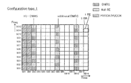
- FIG. 3A is a diagram illustrating an example of a first mapping pattern of the DMRS according to an embodiment.
- FIG. 3A shows an example of a DMRS mapping pattern in the case of focusing on one port (for example, port # 0 or port # 1 in Configuration type 1).
- the mapping pattern illustrated in FIG. 3A indicates the mapping position of DMRS in a resource unit (RU: Resource Unit), which is an example of a resource allocation unit.
- RU Resource Unit
- the RU may be referred to as a slot, a resource block (RB), a resource block pair, or the like.
- One resource block has, for example, a configuration in which 168 resource elements (RE: Resource Element) are aligned in the time direction and 14 in the frequency direction.
- RE resource elements
- One RE is a radio resource area defined by one symbol and one subcarrier. That is, one resource block is composed of 14 symbols and 12 subcarriers.
- the “slot” may be divided into “minislots” in the time direction.
- the “minislot” may be configured by, for example, the number of symbols ranging from 1 symbol to 14 symbols.
- one slot may be considered to correspond to an example of “unit time” in a radio link signal (which may be either a DL signal or a UL signal).
- the “unit time of the wireless link signal” is not limited to “one slot”, and may be a period including the number of symbols set appropriately.
- the period of one hop area described later with reference to FIGS. 7 to 9 may correspond to “a unit time of a wireless link signal”.
- a control channel for example, PDCCH or PUCCH
- PDCCH Physical Downlink Control Channel
- SB1 and SB2 the first two symbols
- the number of symbols in the control channel is not limited to 2 symbols, and may be 3 symbols.
- the control channel may be arranged in any of the first symbol (SB1) to the third symbol (SB3) of one slot.
- a plurality of DMRSs may be distributed in the frequency direction.
- DMRSs FL-DMRSs and / or A-DMRSs
- IFDM is an abbreviation of “Interleaved Frequency Division Multiplexing”.
- a data signal (PDSCH or PUSCH) may be allocated to REs in which DMRSs from the third symbol to the 14th symbol are not allocated.
- An RE for which DMRS and other signals are not arranged when focusing on one port may be referred to as “Null RE”.
- CSI-RS is an abbreviation of "Channel State Information-Reference Signal”.
- the FL-DMRS may be placed in the symbol immediately after the symbol in which the control channel is placed in the time direction, for example, the third symbol (SB3) in one slot. .
- the arrangement position of the FL-DMRS in the time direction is not limited to the third symbol (SB3).
- the FL-DMRS may be mapped to the fourth symbol (SB4) or the fifth symbol (SB5).
- the DMRS may be placed at the beginning of the symbol to which the PUSCH is mapped.
- the number of symbols in which the FL-DMRSs are arranged is not limited to one symbol.
- FL-DMRSs may be arranged in two symbols in one slot.
- the FL-DMRS may be arranged in the third symbol (SB3) and the fourth symbol (SB4) of one slot.
- the A-DMRS may be arranged in a symbol spaced apart in the time direction from the symbol in which the FL-DMRS is arranged in one slot.
- A-DMRSs When A-DMRSs are allocated to one symbol in one slot, A-DMRSs may be allocated to the 12th symbol (SB12) as shown in FIG. 3A, for example. When A-DMRSs are arranged in two symbols in one slot, A-DMRSs may be arranged, for example, in the eighth symbol (SB8) and the twelfth symbol (SB12) (for example, see FIG. 5A described later) . When A-DMRSs are allocated to three symbols in one slot, A-DMRSs may be allocated to, for example, the sixth symbol (SB6), the ninth symbol (SB9), and the twelfth symbol (SB12).
- the A-DMRSs may be arranged in the frequency direction at the same density as the arrangement density in the frequency direction of the FL-DMRSs.
- A-DMRSs may be arranged in the frequency direction in the same pattern as the arrangement pattern of FL-DMRSs in the frequency direction, as shown in FIG. 3A.
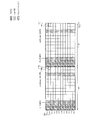
- FIG. 3B is a diagram showing an example of a second mapping pattern of DMRS in the present embodiment.
- FIG. 3B shows an example of a DMRS mapping pattern in the case of focusing on one port (for example, port # 0 or port # 1 in configuration type 1).
- a control channel for example, PDCCH or PUCCH
- PDCCH Physical Downlink Control Channel
- SB1 and SB2 the first two symbols
- the number of symbols in the control channel is not limited to 2 symbols, and may be 3 symbols.
- the control channel may be arranged in any of the first symbol (SB1) to the third symbol (SB3) of one slot.
- a plurality of DMRSs may be distributed in the frequency direction.
- DMRSs (FL-DMRSs and / or A-DMRSs) of the same port may be spaced by 4 subcarriers.
- the interval at which DMRSs (FL-DMRSs and / or A-DMRSs) of the same port are arranged in the frequency direction is not limited to four subcarriers.
- a data signal (PDSCH or PUSCH) may be allocated to REs in which DMRSs from the third symbol to the 14th symbol are not allocated.
- An RE for which DMRS and other signals are not arranged when focusing on one port may be referred to as “Null RE”.
- DMRS when focusing on one port, DMRS, a signal of a data channel (for example, PDSCH or PUSCH), or DMRS when focusing on another port May be placed at the position of “Null RE” (eg, CSI-RS).
- the FL-DMRS may be arranged in the symbol immediately after the symbol in which the control channel is arranged in the time direction, for example, the third symbol (SB3) in one slot.
- the arrangement position of the FL-DMRS in the time direction is not limited to the third symbol (SB3).
- the FL-DMRS may be mapped to the fourth symbol (SB4) or the fifth symbol (SB5).
- the DMRS may be placed at the beginning of the symbol to which the PUSCH is mapped.
- the number of symbols in which the FL-DMRSs are arranged is not limited to one symbol.
- FL-DMRSs may be arranged in two symbols in one slot.
- the FL-DMRS may be arranged in the third symbol (SB3) and the fourth symbol (SB4) of one slot.
- the A-DMRS may be arranged in a symbol spaced apart in the time direction from the symbol in which the FL-DMRS is arranged in one slot.
- A-DMRSs When A-DMRSs are allocated to one symbol in one slot, A-DMRSs may be allocated to the 12th symbol (SB12) as shown in FIG. 3B, for example. When A-DMRSs are arranged in two symbols in one slot, A-DMRSs may be arranged, for example, in the eighth symbol (SB8) and the twelfth symbol (SB12) (for example, see FIG. 5B described later) . When A-DMRSs are allocated to three symbols in one slot, A-DMRSs may be allocated to, for example, the sixth symbol (SB6), the ninth symbol (SB9), and the twelfth symbol (SB12).
- the A-DMRSs may be arranged in the frequency direction at the same density as the arrangement density in the frequency direction of the FL-DMRSs.
- A-DMRSs may be arranged in the frequency direction in the same pattern as the arrangement pattern of FL-DMRSs in the frequency direction, as shown in FIG. 3B.
- mapping pattern regarding DMRS mentioned above is an example, and this invention is not limited to this.
- DMRS collision If multiple cells use the same mapping pattern illustrated in FIG. 3A or 3B for the same port number, DMRS collisions occur between the cells. For example, in the situation where the same Configuration type is set and the same port number is used among a plurality of cells, the same mapping pattern may result. When a collision between DMRSs occurs between cells, the channel estimation accuracy using the DMRS on the receiving side of the radio signal is degraded, and the reception characteristic of the radio signal is degraded.
- the DMRS mapping position is changed to different frequencies at different times (for convenience, this may be referred to as “frequency hopping”), thereby reducing the probability of DMRS collisions between different cells. Do.
- the frequency hopping of DMRS can prevent the same DMRS mapping pattern from being used between different cells. Thereby, it is possible to achieve randomization of interference between DMRSs. Therefore, a decrease in channel estimation accuracy using DMRS can be suppressed, and a decrease in reception characteristics of radio signals can be suppressed.
- FIGS. 4A and 4B are diagrams showing a first example of DMRS frequency hopping according to an embodiment.
- FIG. 4A shows an example of frequency hopping of DMRS based on the first mapping pattern (Configuration type 1).
- FIG. 4B shows an example of frequency hopping of DMRS based on the second mapping pattern (Configuration type 2).
- control channels eg, PDCCH or PUCCH
- pattern of FL-DMRS may be the same as those in FIGS. 3A and 3B, respectively.
- A-DMRSs are mapped (frequency hopping) to different frequencies as compared with FIGS. 3A and 3B.
- the arrangement pattern of A-DMRSs arranged in the 12th symbol (SB12) in the frequency direction of the A-DMRSs corresponds to the arrangement direction of one subcarrier by the amount of Corresponds to the shifted pattern.
- the arrangement pattern of the A-DMRSs arranged in the SB 12 in the frequency direction corresponds to a pattern shifted in the frequency direction by two subcarriers as compared to FIG. 3B.
- FIG. 4A when the arrangement pattern in the frequency direction of A-DMRS is frequency-shifted cyclically by two or more even-numbered subcarriers, the arrangement pattern in the frequency direction becomes the same as the pattern of FIG. 3A. Therefore, in the case of FIG. 4A, there are two arrangement patterns (two patterns) as A-DMRS arrangement patterns.
- the frequency shift amount of the arrangement pattern of A-DMRS is one subcarrier
- the arrangement pattern in the frequency direction is six ways (six patterns), and three cases for two subcarriers. 3 patterns).
- the frequency shift amount is not limited to these.
- 4A and 4B is an example in which frequency hopping of A-DMRS is performed among FL-DMRS and A-DMRS, but conversely, frequency hopping of FL-DMRS may be performed.
- both FL-DMRS and A-DMRS may be frequency hopping individually.
- FIGS. 5A and 5B illustrate a second example of DMRS frequency hopping according to an embodiment.
- FIG. 5A shows an example of DMRS frequency hopping based on a first mapping pattern (Configuration type 1)
- FIG. 5B shows a DMRS frequency based on a second mapping pattern (Configuration type 2).
- An example of hopping is shown.
- a plurality of A-DMRSs may be distributed in the time direction in one slot.
- an A-DMRS may be arranged for each of the eighth symbol (SB8) and the twelfth symbol (SB12) of one slot.
- the arrangement of control channels (for example, PDCCH or PUCCH) and the arrangement of FL-DMRSs may be the same as those in FIGS. 3A and 3B, respectively.
- the plurality of A-DMRSs may be individually frequency hopping.
- the first A-DMRS may be frequency hopping.
- the second A-DMRS located at SB 12 may be frequency hopped.
- the frequency hopping amount may be the same or different for the first A-DMRS and the second A-DMRS.
- a different mapping pattern may be applied in the frequency direction for each of a plurality of A-DMRSs, or the same mapping pattern may be applied in the frequency direction for all A-DMRSs.
- both the first A-DMRS disposed in SB 8 and the second A-DMRS disposed in SB 12 may be frequency hopping.
- the frequency hopping amount may be the same as or different between the first A-DMRS placed in SB 8 and the second A-DMRS placed in SB 12.
- FIG. 5B shows an example in which the first A-DMRS performs frequency hopping by two subcarriers, and the second A-DMRS disposed in the SB 12 performs frequency hopping by four subcarriers.
- first and second A-DMRSs may be frequency hopping.
- frequency hopping may be performed individually also in a case where, for example, A-DMRSs are arranged in each of SB6, SB9 and SB12.
- the frequency hopping amount may be the same for three symbols of A-DMRS, or may be different for all or part of three symbols of A-DMRS.
- FIGS. 5A and 5B are examples in which frequency hopping of the FL-DMRS is not performed, the frequency hopping of the FL-DMRS may be performed.
- the A-DMRS may not perform frequency hopping or may perform frequency hopping.
- the same A-DMRS arrangement among different cells It can prevent the pattern from being used continuously. This makes it possible to randomize the interference between A-DMRSs. Therefore, it is possible to suppress a decrease in channel estimation accuracy using A-DMRS, and to suppress a decrease in reception characteristics of a radio signal.
- FIG. 6 is a diagram showing a third example of DMRS frequency hopping according to an embodiment.
- the third example is an example in which the mapping position in the frequency direction of the DMRS is changed on a slot basis.
- both FL-DMRS and A-DMRS are equivalent to one subcarrier.
- a frequency hopping constellation pattern may be applied.
- the FL-DMRS may not be frequency hopping, as in FIG. 4A. Also, in the first slot, one of the FL-DMRS and the A-DMRS may be frequency hopping as described in FIG. 4A.
- the arrangement pattern of DMRSs (FL-DMRSs and / or A-DMRSs) in the frequency direction may be different in one or both of the slots and in the slots.
- the DMRS arrangement pattern illustrated in FIG. 5A may be applied, and in the second slot, the DMRS arrangement pattern illustrated in FIG. 5B may be applied.
- any two of the DMRS arrangement patterns illustrated in FIGS. 4A, 4B, 5A, and 5B may be selectively applied to two slots.
- the DMRS arrangement pattern illustrated in FIG. 4A or 4B may be applied, and in the second slot, the DMRS arrangement pattern illustrated in FIG. 5A or 5B may be applied.
- the DMRS arrangement pattern illustrated in FIG. 5A or 5B is applied, and in the second slot, the DMRS arrangement pattern illustrated in FIG. 4A or 4B is applied. It is also good.
- the arrangement pattern of FIG. 4A, FIG. 4B, FIG. 5A and / or FIG. 5B and other arrangement patterns may be selectively applied in units of one or more slots.
- FIGS. 7 to 9 illustrate a fourth example of DMRS frequency hopping according to an embodiment.
- the fourth example is a frequency hopping example of DMRS when frequency hopping in a slot is applied in UL.
- FIGS. 7, 8 and 9 show frequency hopping examples of DMRS based on the first mapping pattern (Configuration type 1).
- one slot may be divided into a first hop area (SB1 to SB7) and a second hop area (SB8 to SB14) in the time direction.
- the second hop region is hopped to a lower frequency band than the first hop region. Note that the second hop region may hop to a frequency band higher than the first hop region.
- a control channel for example, PUCCH
- PUCCH may be allocated to REs of the first two symbols (SB1 and SB2) of the first hop region.
- the number of symbols of the control channel is not limited to two symbols, and may be three symbols.
- the control channel may be arranged in any of the first symbol (SB1) to the third symbol (SB3) of one slot.
- the DMRS may be disposed at the third symbol (SB3) of the first hop region.
- the arrangement position of the DMRS in the time direction is not limited to the third symbol (SB3).
- the DMRS may be mapped to the fourth symbol (SB4) or the fifth symbol (SB5).
- the number of symbols in which the DMRS in the first hop region is arranged is not limited to one symbol.
- DMRSs may be arranged in two symbols in the first hop region.
- DMRSs may be arranged at the third symbol (SB3) and the fourth symbol (SB4).
- the DMRS may be placed at the beginning (eg, SB8) of the symbol to which the PUSCH is mapped.
- the mapping positions of DMRSs may be hopped to different frequencies in the first hop area and the second hop area.
- the DMRS mapped to the leading symbol (SB8) of the second hop area may be frequency hopping.
- the DMRSs mapped to the leading symbol (SB 8) of the second hop area may frequency hop the DMRSs arranged in the third symbol of the first hop area without hopping.
- DMRS mapping positions may be frequency hopping individually for both the first hop region and the second hop region.
- a plurality of DMRSs may be distributed and arranged in the time direction in the first hop region and / or the second hop region.
- each of the first hop area and the second hop area is regarded as a "slot", and any one of DMRS arrangement patterns described in FIGS. 4A and 5A is selectively applied to any hop area. It is also good.
- the DMRS may be arranged in the third symbol (SB3) and the end symbol (the seventh symbol (SB7)) of the first hop region.
- the DMRS placed in the last symbol of the first hop area may be considered to correspond to “A-DMRS”.
- DMRSs of three symbols may be distributed and arranged in the time direction.
- DMRSs may be allocated to the leading symbol (SB8) and the trailing symbol (SB14).
- SB8 leading symbol
- SB14 trailing symbol
- DMRSs of three symbols may be distributed and arranged in the time direction.
- a plurality of DMRSs are disposed in each of the first hop region and the second hop region, but a plurality of DMRSs are disposed in only one of the first hop region and the second hop region.
- the DMRS may not be arranged at the end symbol (SB7) of the first hop area.
- the DMRS may be arranged only in one of the leading symbol (SB8) and the end symbol (SB14) of the second hop area, and the DMRS may not be arranged in the other.
- the DMRS mapping positions may be hopped to different frequencies in the first hop area and the second hop area.
- the DMRS mapped to the SB 14 may be frequency hopping.
- the DMRS mapped to SB8 may be frequency hopping.
- mapping positions may be hopped to relatively different frequencies.
- different DMRS mapping patterns may be applied to the first hop area and the second hop area.
- each of the first hop area and the second hop area in FIGS. 8 and 9 is regarded as a “slot”, and any one of the DMRS arrangement patterns described in FIGS. 4B and 5B can be selectively selected. It may be applied to the hop area.
- the number of hop areas is not limited to two. Three or more hop regions may be set in the time direction. When three or more hop areas are set, frequency hopping (pattern) exemplified in FIG. 7 or 8 may be applied to part or all of each hop area.
- the plurality of hop areas are not limited to the case where the same number of symbols are included, respectively, and may be configured by different numbers of symbols.
- the number of hop areas is 2, the first hop area may be configured by 10 symbols, and the second hop area may be configured by 4 symbols.
- the fourth example of DMRS frequency hopping described above it can be suppressed that the same DMRS arrangement pattern is continuously used among user terminals 20 of different cells with respect to the UL signal. Thereby, it is possible to achieve randomization of interference between DMRSs. Therefore, in the radio base station 10 which is the reception side of the UL signal, it is possible to suppress the decrease in channel estimation accuracy using the DMRS, and it is possible to suppress the decrease in the reception characteristic of the UL signal.
- the frequency hopping (pattern) of DMRS for the DL signal and the UL signal may be set by the radio base station 10, for example.
- the arrangement position of the DMRS with respect to the DL signal may be determined based on the determined frequency hopping pattern, and the DMRS may be mapped to the arrangement position.
- the user terminal 20 receives notification of information on the frequency hopping (pattern) determined in the radio base station 10, specifies the DMRS arrangement position, and receives the DL signal or maps the DMRS to the UL signal. I do.
- Notification of information on the frequency hopping (pattern) of DMRS enables flexible change of the arrangement position of DMRS as needed.
- the mapping patterns for a plurality of cells are determined in the upper layer and set in the corresponding radio base station 10. Good.
- Notification of information on DMRS frequency hopping The “notification” of the information on the frequency hopping (pattern) of the DMRS described above may be implicitly performed or may be explicitly performed in association with some information.
- Cell ID, user index, slot index, and symbol index are mentioned as a non-limiting example of the information with which information on frequency hopping (pattern) of DMRS is associated in implicit notification.
- Information on DMRS frequency hopping may be associated with any one or more of the cell ID, the user index, the slot index, and the symbol index. The association allows the frequency hopping (pattern) of the DMRS to be identified implicitly, thereby reducing signaling for notification.
- Radio Resource Control RRC
- MAC layer signaling and / or physical (PHY) layer signaling may be used, or hybrid indication combining the above (a) and (b) may be used.
- DCI of PDCCH may be used, and DCI may indicate information on frequency hopping (pattern) of DMRS.
- information on frequency hopping (pattern) of DMRS may be associated with information indicating presence or absence of sequence hopping.
- information indicating the frequency hopping “absent” and “presence” of the DMRS may be associated with information indicating the sequence hopping “present” and “absent”, respectively.
- information on frequency hopping (pattern) of DMRS may be notified by higher layer signaling.
- information on frequency hopping (pattern) of DMRS may be identified by a combination of a plurality of pieces of information exemplified above.
- the size (number of symbols) in the time direction of the control channel is not limited to 2, and may be 0, 1, or 3, for example. Also, the PDCCH signal may be inserted into part of the symbol.
- the arrangement position of DMRS is not limited to the third symbol of one slot.
- the arrangement position of DMRS may be the fourth symbol of one slot, the head symbol of a data channel (for example, PUSCH), or the second symbol of PUSCH.
- the number of symbols in which DMRSs are arranged is not limited to one.
- the DMRS may be arranged across two symbols of the third symbol and the fourth symbol of one slot, or may be arranged across two symbols of the fourth symbol and the fifth symbol of one slot.
- the PDSCH may be referred to as a downlink data channel.
- the PUSCH may be referred to as an upstream data channel.
- the PDCCH may be referred to as a downlink control channel.
- the PUCCH may be referred to as an uplink control channel.
- each functional block may be realized by one physically and / or logically coupled device, or directly and / or indirectly two or more physically and / or logically separated devices. It may be connected by (for example, wired and / or wireless) and realized by the plurality of devices.
- the wireless base station 10, the user terminal 20, and the like in one embodiment of the present invention may function as a computer that performs the processing of the wireless communication method of the present invention.
- FIG. 10 is a diagram showing an example of the hardware configuration of the radio base station 10 and the user terminal 20 according to an embodiment.
- the above-described wireless base station 10 and user terminal 20 may be physically configured as a computer device including a processor 1001, a memory 1002, a storage 1003, a communication device 1004, an input device 1005, an output device 1006, a bus 1007 and the like. Good.
- the term “device” can be read as a circuit, a device, a unit, or the like.
- the hardware configuration of the radio base station 10 and the user terminal 20 may be configured to include one or more of the devices illustrated in FIG. 10 or may be configured without including some devices.
- processor 1001 may be implemented by one or more chips.
- Each function in the radio base station 10 and the user terminal 20 performs a calculation by causing the processor 1001 to read predetermined software (program) on hardware such as the processor 1001 and the memory 1002, and performs communication by the communication device 1004 or This is realized by controlling reading and / or writing of data in the memory 1002 and the storage 1003.
- the processor 1001 operates, for example, an operating system to control the entire computer.
- the processor 1001 may be configured by a central processing unit (CPU: Central Processing Unit) including an interface with a peripheral device, a control device, an arithmetic device, a register, and the like.
- CPU Central Processing Unit
- the above-described scheduler 101, transmission signal generation units 102 and 206, coding / modulation units 103 and 207, mapping units 104 and 208, control units 108 and 203, channel estimation units 109 and 204, demodulation / decoding units 110 and 205 And the like may be realized by the processor 1001.
- the processor 1001 reads a program (program code), a software module or data from the storage 1003 and / or the communication device 1004 to the memory 1002, and executes various processing according to these.
- a program a program that causes a computer to execute at least a part of the operations described in the above embodiments is used.
- the scheduler 101 of the radio base station 10 may be realized by a control program stored in the memory 1002 and operated by the processor 1001, or may be realized similarly for other functional blocks.
- the various processes described above have been described to be executed by one processor 1001, but may be executed simultaneously or sequentially by two or more processors 1001.
- the processor 1001 may be implemented by one or more chips.
- the program may be transmitted from the network via a telecommunication line.
- the memory 1002 is a computer readable recording medium, and includes, for example, at least one of a ROM (Read Only Memory), an EPROM (Erasable Programmable ROM), an EEPROM (Electrically Erasable Programmable ROM), and a RAM (Random Access Memory). It may be done.
- the memory 1002 may be called a register, a cache, a main memory (main storage device) or the like.
- the memory 1002 can store a program (program code), a software module, and the like that can be executed to implement the wireless communication method according to an embodiment of the present invention.
- the storage 1003 is a computer readable recording medium, and for example, an optical disc such as a CD-ROM (Compact Disc ROM), a hard disc drive, a flexible disc, a magneto-optical disc (eg, a compact disc, a digital versatile disc, a Blu-ray A (registered trademark) disk, a smart card, a flash memory (for example, a card, a stick, a key drive), a floppy (registered trademark) disk, a magnetic strip, and the like may be used.
- the storage 1003 may be called an auxiliary storage device.
- the above-mentioned storage medium may be, for example, a database including the memory 1002 and / or the storage 1003, a server or any other suitable medium.
- the communication device 1004 is hardware (transmission / reception device) for performing communication between computers via a wired and / or wireless network, and is also called, for example, a network device, a network controller, a network card, a communication module, or the like.
- a network device for example, a network controller, a network card, a communication module, or the like.
- the above-described transmission units 105 and 209, antennas 106 and 201, and reception units 107 and 202 may be realized by the communication device 1004.
- the input device 1005 is an input device (for example, a keyboard, a mouse, a microphone, a switch, a button, a sensor, and the like) that receives an input from the outside.
- the output device 1006 is an output device (for example, a display, a speaker, an LED lamp, etc.) that performs output to the outside.
- the input device 1005 and the output device 1006 may be integrated (for example, a touch panel).
- each device such as the processor 1001 and the memory 1002 is connected by a bus 1007 for communicating information.
- the bus 1007 may be configured by a single bus or may be configured by different buses among the devices.
- radio base station 10 and the user terminal 20 may be microprocessors, digital signal processors (DSPs), application specific integrated circuits (ASICs), programmable logic devices (PLDs), field programmable gate arrays (FPGAs), etc. It may be configured to include hardware, and part or all of each functional block may be realized by the hardware. For example, processor 1001 may be implemented in at least one of these hardware.
- DSPs digital signal processors
- ASICs application specific integrated circuits
- PLDs programmable logic devices
- FPGAs field programmable gate arrays
- notification of information is not limited to the aspect / embodiment described herein, and may be performed by other methods.
- notification of information may be physical layer signaling (for example, Downlink Control Information (DCI), Uplink Control Information (UCI)), upper layer signaling (for example, Radio Resource Control (RRC) signaling, Medium Access Control (MAC) signaling, It may be implemented by broadcast information (MIB (Master Information Block), SIB (System Information Block)), other signals, or a combination thereof.
- RRC signaling may be referred to as an RRC message, and may be, for example, an RRC connection setup (RRC Connection Setup) message, an RRC connection reconfiguration (RRC Connection Reconfiguration) message, or the like.
- Each aspect / embodiment described in the present specification is LTE (Long Term Evolution), LTE-A (LTE-Advanced), SUPER 3G, IMT-Advanced, 4G, 5G, FRA (Future Radio Access), W-CDMA (Registered trademark), GSM (registered trademark), CDMA2000, UMB (Ultra Mobile Broadband), IEEE 802.11 (Wi-Fi), IEEE 802.16 (WiMAX), IEEE 802.20, UWB (Ultra-Wide Band),
- the present invention may be applied to a system utilizing Bluetooth (registered trademark), other appropriate systems, and / or an advanced next-generation system based on these.
- the specific operation supposed to be performed by the base station (radio base station) in this specification may be performed by the upper node in some cases.
- the various operations performed for communication with the terminals may be performed by the base station and / or other network nodes other than the base station (for example, it is clear that it may be performed by MME (Mobility Management Entity) or S-GW (Serving Gateway), but not limited thereto.
- MME Mobility Management Entity
- S-GW Serving Gateway
- Information, signals, etc. may be output from the upper layer (or lower layer) to the lower layer (or upper layer). Input and output may be performed via a plurality of network nodes.
- the input / output information may be stored in a specific place (for example, a memory), or may be managed by a management table. Information to be input or output may be overwritten, updated or added. The output information may be deleted. The input information or the like may be transmitted to another device.
- the determination may be performed by a value (0 or 1) represented by one bit, may be performed by a boolean value (Boolean: true or false), or may be compared with a numerical value (for example, a predetermined value). Comparison with the value).
- Software may be called software, firmware, middleware, microcode, hardware description language, or any other name, and may be instructions, instruction sets, codes, code segments, program codes, programs, subprograms, software modules. Should be interpreted broadly to mean applications, software applications, software packages, routines, subroutines, objects, executables, threads of execution, procedures, functions, etc.
- software, instructions, etc. may be sent and received via a transmission medium.
- software may use a wireline technology such as coaxial cable, fiber optic cable, twisted pair and digital subscriber line (DSL) and / or a website, server or other using wireless technology such as infrared, radio and microwave When transmitted from a remote source, these wired and / or wireless technologies are included within the definition of transmission medium.
- wireline technology such as coaxial cable, fiber optic cable, twisted pair and digital subscriber line (DSL) and / or a website, server or other using wireless technology such as infrared, radio and microwave
- Information, signal The information, signals, etc. described herein may be represented using any of a variety of different techniques.
- data, instructions, commands, information, signals, bits, symbols, chips etc may be voltage, current, electromagnetic waves, magnetic fields or particles, optical fields or photons, or any of these May be represented by a combination of
- the channels and / or symbols may be signals.
- the signal may be a message.
- the component carrier (CC) may be called a carrier frequency, a cell or the like.
- radio resources may be indexed.
- a base station can accommodate one or more (e.g., three) cells (also called sectors). If the base station accommodates multiple cells, the entire coverage area of the base station can be divided into multiple smaller areas, each smaller area being a base station subsystem (eg, a small base station RRH for indoor use: Remote Communication service can also be provided by Radio Head.
- the terms "cell” or “sector” refer to a base station that provides communication services in this coverage and / or part or all of the coverage area of a base station subsystem.
- the terms “base station”, “eNB”, “gNB”, “cell” and “sector” may be used interchangeably herein.
- a base station may be called in terms of a fixed station (Node station), NodeB, eNodeB (eNB), gNodeB (gNB) access point, access point, femtocell, small cell, and the like.
- the user terminal may be a mobile station, a subscriber station, a mobile unit, a subscriber unit, a wireless unit, a remote unit, a mobile device, a wireless device, a wireless communication device, a remote communication device, a mobile subscriber station, an access terminal, a mobile terminal by a person skilled in the art It may also be called a terminal, a wireless terminal, a remote terminal, a handset, a user agent, a mobile client, a client, a UE (User Equipment), or some other suitable term.
- determining may encompass a wide variety of operations.
- “Judgment”, “decision” are, for example, judging, calculating, calculating, processing, processing, deriving, investigating, looking up (for example, a table) (Searching in a database or another data structure), ascertaining may be regarded as “decision”, “decision”, etc.
- “determination” and “determination” are receiving (e.g. receiving information), transmitting (e.g. transmitting information), input (input), output (output), access (accessing) (for example, accessing data in a memory) may be regarded as “judged” or “decided”.
- connection means any direct or indirect connection or coupling between two or more elements, It can include the presence of one or more intermediate elements between two elements that are “connected” or “coupled”.
- the coupling or connection between elements may be physical, logical or a combination thereof.
- the two elements are by using one or more wires, cables and / or printed electrical connections, and radio frequency as some non-limiting and non-exclusive examples. It can be considered “connected” or “coupled” to one another by using electromagnetic energy such as electromagnetic energy having wavelengths in the region, microwave region and light (both visible and invisible) regions.
- the reference signal may be abbreviated as RS (Reference Signal), and may be called a pilot (Pilot) according to the applied standard.
- RS Reference Signal
- DMRS may be another corresponding name, such as demodulation RS or DM-RS.
- the phrase “based on” does not mean “based only on,” unless expressly stated otherwise. In other words, the phrase “based on” means both “based only on” and “based at least on.”
- a radio frame may be comprised of one or more frames in the time domain. Each frame or frames in the time domain may be referred to as subframes, time units, and so on.
- a subframe may be further comprised of one or more slots in the time domain.
- the slot may be further configured by one or more symbols (such as Orthogonal Frequency Division Multiplexing (OFDM) symbols, Single Carrier-Frequency Division Multiple Access (SC-FDMA) symbols, etc.) in the time domain.
- OFDM Orthogonal Frequency Division Multiplexing
- SC-FDMA Single Carrier-Frequency Division Multiple Access
- a radio frame, a subframe, a slot, a minislot, and a symbol all represent time units when transmitting a signal.
- a radio frame, a subframe, a slot, a minislot, and a symbol may be another name corresponding to each.
- the base station performs scheduling to assign radio resources (frequency bandwidth usable in each mobile station, transmission power, etc.) to each mobile station.
- the minimum time unit of scheduling may be called a TTI (Transmission Time Interval).
- one subframe may be called a TTI
- a plurality of consecutive subframes may be called a TTI
- one slot may be called a TTI
- one minislot may be called a TTI
- a resource unit is a resource allocation unit in time domain and frequency domain, and may include one or more consecutive subcarriers in frequency domain.
- the time domain of the resource unit may include one or more symbols, and may be one slot, one minislot, one subframe, or one TTI long.
- One TTI and one subframe may be configured of one or more resource units, respectively.
- resource units may be referred to as resource blocks (RBs), physical resource blocks (PRBs: physical RBs), PRB pairs, RB pairs, scheduling units, frequency units, and subbands.
- a resource unit may be configured of one or more REs.
- 1 RE may be a resource of a unit smaller than the resource unit serving as a resource allocation unit (for example, the smallest resource unit), and is not limited to the name of RE.
- the above-described radio frame structure is merely an example, and the number of subframes included in the radio frame, the number of slots included in the subframe, the number of minislots included in the subframe, and the symbols and resource blocks included in the slots.
- the number and the number of subcarriers included in the resource block can be variously changed.
- notification of predetermined information is not limited to what is explicitly performed, but is performed by implicit (for example, not notifying of the predetermined information) It is also good.
- One aspect of the present invention is useful for a mobile communication system.
Abstract
無線送信装置は、復調用参照信号を含む無線リンク信号を送信する送信部(105)と、制御部(101)と、を備えてよい。制御部(101)は、前記無線リンク信号の無線リソースに前記復調用参照信号をマッピングする位置を、異なる時間において異なる周波数にホッピングしてよい。
Description
本発明は、無線送信装置および無線受信装置に関する。
UMTS(Universal Mobile Telecommunication System)ネットワークにおいて、更なる高速データレート、低遅延などを目的としてロングタームエボリューション(LTE:Long Term Evolution)が仕様化された(非特許文献1)。また、LTEからの更なる広帯域化及び高速化を目的として、LTEの後継システムも検討されている。LTEの後継システムには、例えば、LTE-A(LTE-Advanced)、FRA(Future Radio Access)、5G(5th generation mobile communication system)、5G+(5G plus)、New-RAT(Radio Access Technology)などと呼ばれるものがある。
将来の無線通信システム(例えば、5G)では、低いキャリア周波数から高いキャリア周波数まで幅広い周波数をサポートすることが期待されている。例えば、低いキャリア周波数、高いキャリア高周波数などの周波数帯毎に伝搬チャネル環境、及び/又は、要求条件が大きく異なることから、将来の無線通信システムでは、参照信号などの配置(「マッピング」と称してもよい)を柔軟にサポートすることが望まれる。
例えば、将来の無線通信システムでは、ユーザ端末に割り当てられたポート(レイヤ)の参照信号(例えば、復調用参照信号)が、様々な方法に基づいて無線リソースに配置され、ユーザ端末に対して送信されることが想定される。その場合、ユーザ端末に割り当てられたポートに関する情報、および、参照信号(Reference Signal, RS)の配置方法に関する情報は、例えば、無線基地局からユーザ端末へ通知される。
また、将来の無線通信システムでは、サブフレーム(又は、スロット)内におけるチャネル推定及び信号復調に要する処理時間の短縮を実現するため、復調用参照信号を、サブフレームの前方にマッピングすることが検討されている(非特許文献2)。なお、復調用参照信号は、「DMRS」(Demodulation Reference Signal)、「DM-RS」、又は、「復調用RS」と表記されてもよい。
3GPP TS 36.300 v13.4.0, "Evolved Universal Terrestrial Radio Access (E-UTRA) and Evolved Universal Terrestrial Radio Access Network (E-UTRAN); Overall description; Stage 2 (Release 13)," June 2016
R1-165575, Qualcomm, Ericsson, Panasonic, NTT Docomo, ZTE, Convida, Nokia, ASB, Sony, Intel, "Way Forward On Frame Structure," May 2016.
異なるセル間に、DMRSに関して同じマッピングパターンが適用された場合、異なるセル間のDMRSどうしの衝突が生じることがある。DMRSどうしの衝突が生じた場合、DMRSを用いたチャネル推定精度が低下するため、無線信号の受信特性が低下し得る。
本発明の目的の1つは、セル間における復調用参照信号どうしの衝突発生率を低減して、無線信号の受信特性低下を抑制することにある。
本発明の一態様に係る無線送信装置は、復調用参照信号を含む無線リンク信号を送信する送信部と、前記無線リンク信号の無線リソースに前記復調用参照信号をマッピングする位置を、異なる時間において異なる周波数にホッピングする制御部と、を備えてよい。
また、本発明の一態様に係る無線受信装置は、復調用参照信号を含む無線リンク信号を受信する受信部と、前記復調用参照信号を用いて、前記無線リンク信号を受信処理する処理部と、を備え、前記復調用参照信号が前記無線リンク信号の無線リソースにマッピングされている位置は、異なる時間において異なる周波数にホッピングされている。
本発明の一態様によれば、セル間における復調用参照信号どうしの衝突発生率を低減できるため、無線信号の受信特性低下を抑制できる。
以下、本発明の一実施の形態について、図面を参照して詳細に説明する。
(一実施の形態)
本実施の形態に係る無線通信システムは、図1に示す無線基地局10(例えば、eNB(eNodeB)またはgNB(gNodeB)とも呼ばれる)、及び、図2に示すユーザ端末20(例えば、UE(User Equipment)とも呼ばれる)を備える。ユーザ端末20は、無線基地局10と無線接続(無線アクセス)される。別言すると、無線基地局10とユーザ端末20との間に無線リンクが形成される。
本実施の形態に係る無線通信システムは、図1に示す無線基地局10(例えば、eNB(eNodeB)またはgNB(gNodeB)とも呼ばれる)、及び、図2に示すユーザ端末20(例えば、UE(User Equipment)とも呼ばれる)を備える。ユーザ端末20は、無線基地局10と無線接続(無線アクセス)される。別言すると、無線基地局10とユーザ端末20との間に無線リンクが形成される。
無線リンクを伝搬する無線信号は、無線リンク信号と称されてよい。無線基地局10からユーザ端末20への方向の無線リンクは、下りリンク(DL:Downlink)と称されてよい。したがって、無線基地局10からユーザ端末20へ送信される無線リンク信号は、DL信号と称されてよい。これに対し、ユーザ端末20から無線基地局10へ送信される無線リンクは、上りリンク(UL:Uplink)と称されてよい。したがって、ユーザ端末20から無線基地局10へ送信される無線リンク信号は、UL信号と称されてよい。
無線基地局10は、ユーザ端末20に対して、DL制御チャネル(例えば、PDCCH:Physical Downlink Control Channel)を用いてDL制御信号を送信する。無線基地局10は、ユーザ端末20に対して、DLデータチャネル(例えば、DL共有チャネル:PDSCH:Physical Downlink Shared Channel)を用いてDLデータ信号、DM-RSを送信する。
また、ユーザ端末20は、無線基地局10に対して、UL制御チャネル(例えば、PUCCH:Physical Uplink Control Channel)あるいはULデータチャネル(例えば、UL共有チャネル:PUSCH:Physical Uplink Shared Channel)を用いてUL制御信号を送信する。ユーザ端末20は、無線基地局10に対して、ULデータチャネル(例えば、UL共有チャネル:PUSCH:Physical Uplink Shared Channel)を用いてULデータ信号、DMRSを送信する。
本実施の形態における無線通信システムでは、一例として、2種類のDMRSのマッピングパターン(Configuration type 1 and 2)をサポートする。そして、本実施の形態における無線通信システムでは、様々なDMRSの配置方法をサポートする。
なお、無線基地局10及びユーザ端末20が送受信する下りチャネル及び上りチャネルは、上記のPDCCH、PDSCH、PUCCH、PUSCHなどに限定されない。無線基地局10及びユーザ端末20が送受信する下りチャネル及び上りチャネルは、例えば、PBCH(Physical Broadcast Channel)、RACH(Random Access Channel)などの他のチャネルでもよい。
また、図1及び図2では、無線基地局10及びユーザ端末20において生成されるDL、及び/又は、ULの信号波形は、OFDM(Orthogonal Frequency Division Multiplexing)変調に基づく信号波形でもよい。あるいは、DL、及び/又は、ULの信号波形は、SC-FDMA(Single Carrier-Frequency Division Multiple Access)又はDFT-S-OFDM(DFT-Spread-OFDM))に基づく信号波形でもよい。あるいは、DL、及び/又は、ULの信号波形は、他の信号波形でもよい。図1及び図2では、信号波形を生成するための構成部(例えば、IFFT処理部、CP付加部、CP除去部、FFT処理部など)の記載を省略している。
<無線基地局>
図1は、本実施の形態に係る無線基地局10の全体構成の一例を示すブロック図である。無線基地局10は、スケジューラ101と、送信信号生成部102と、符号化・変調部103と、マッピング部104と、送信部105と、アンテナ106と、受信部107と、制御部108と、チャネル推定部109と、復調・復号部110と、を含む。なお、無線基地局10は、複数のユーザ端末20と同時に通信を行うMU-MIMO(Multi-User Multiple-Input Multiple-Output)の構成を有しても良い。あるいは、無線基地局10は、1つのユーザ端末20と通信を行うSU-MIMO(Single-User Multiple-Input Multiple-Output)の構成を有していても良い。あるいは、無線基地局10は、SU-MIMOおよびMU-MIMOの両方の構成を有していても良い。
図1は、本実施の形態に係る無線基地局10の全体構成の一例を示すブロック図である。無線基地局10は、スケジューラ101と、送信信号生成部102と、符号化・変調部103と、マッピング部104と、送信部105と、アンテナ106と、受信部107と、制御部108と、チャネル推定部109と、復調・復号部110と、を含む。なお、無線基地局10は、複数のユーザ端末20と同時に通信を行うMU-MIMO(Multi-User Multiple-Input Multiple-Output)の構成を有しても良い。あるいは、無線基地局10は、1つのユーザ端末20と通信を行うSU-MIMO(Single-User Multiple-Input Multiple-Output)の構成を有していても良い。あるいは、無線基地局10は、SU-MIMOおよびMU-MIMOの両方の構成を有していても良い。
スケジューラ101は、DL信号(DLデータ信号、DL制御信号、DMRSなど)のスケジューリング(例えば、リソース割当及びポート割当)を行う。また、スケジューラ101は、UL信号(ULデータ信号、UL制御信号、DMRSなど)のスケジューリング(例えば、リソース割当及びポート割当)を行う。
スケジューリングにおいて、スケジューラ101は、DL信号のDMRSがマッピングされるリソース要素を示すマッピングパターンの構成を「Configuration type 1」または「Configuration type 2」の中から1つ選択する。例えば、スケジューラ101は、伝搬路環境(例えば、通信品質および周波数選択性)、及び/又は、要求条件(サポートする端末の移動速度など)、及び/又は、無線基地局10もしくはユーザ端末20の性能に基づいて、Configuration type 1またはConfiguration type 2の中から1つのマッピングパターンを選択する。あるいは、マッピングパターンは、予め1つに決定されていてもよい。
また、スケジューラ101は、スケジューリング情報を送信信号生成部102及びマッピング部104に出力する。スケジューラ101は、後述するように、DL信号にDMRSをマッピングする位置を、異なる時間において異なる周波数にホッピングする制御部の一例と捉えてよい。
また、スケジューラ101は、例えば、無線基地局10とユーザ端末20との間のチャネル品質に基づいて、DLデータ信号及びULデータ信号のMCS(Modulation and Coding Scheme)(符号化率、変調方式など)を設定する。スケジューラ101は、設定したMCSの情報を送信信号生成部102及び符号化・変調部103へ出力する。なお、MCSは、無線基地局10が設定する場合に限定されず、ユーザ端末20が設定してもよい。ユーザ端末20がMCSを設定する場合、無線基地局10は、ユーザ端末20からMCS情報を受信すればよい(図示せず)。
送信信号生成部102は、送信信号(DLデータ信号、DL制御信号を含む)を生成する。例えば、DL制御信号には、スケジューラ101から出力されたスケジューリング情報(例えば、設定情報)又はMCS情報を含むDCIが含まれる。送信信号生成部102は、生成した送信信号を符号化・変調部103に出力する。
符号化・変調部103は、例えば、スケジューラ101から入力されるMCS情報に基づいて、送信信号生成部102から入力される送信信号に対して、符号化処理及び変調処理を行う。符号化・変調部103は、変調後の送信信号をマッピング部104に出力する。
マッピング部104は、スケジューラ101から入力されるスケジューリング情報(例えば、DLのリソース割当など)に基づいて、符号化・変調部103から入力される送信信号を無線リソース(DLリソース)にマッピングする。また、マッピング部104は、スケジューリング情報に基づいて、DMRSを無線リソース(DLリソース)にマッピングする。マッピング部104は、無線リソースにマッピングされたDL信号を送信部105に出力する。
送信部105は、マッピング部104から入力されるDL信号に対して、アップコンバート、増幅などの送信処理を行い、無線周波数信号(DL信号)をアンテナ106から送信する。
受信部107は、アンテナ106で受信された無線周波数信号(UL信号)に対して、増幅、ダウンコンバートなどの受信処理を行い、UL信号を制御部108に出力する。UL信号には、ULデータ信号、DMRSが含まれてよい。
制御部108は、スケジューラ101から入力されるスケジューリング情報(例えば、ULのリソース割当情報など)に基づいて、受信部107から入力されるUL信号からULデータ信号と、DMRSと、を分離(デマッピング)する。そして、制御部108は、ULデータ信号を復調・復号部110に出力しDMRSをチャネル推定部109に出力する。
チャネル推定部109は、UL信号のDMRSを用いてチャネル推定を行い、推定結果であるチャネル推定値を復調・復号部110に出力する。
復調・復号部110は、チャネル推定部109から入力されるチャネル推定値に基づいて、制御部108から入力されるULデータ信号に対して復調及び復号処理を行う。また、復調・復号部110は、復調及び復号されたULデータ信号を、アプリケーション部(図示せず)に転送する。なお、アプリケーション部は、物理レイヤ又はMACレイヤより上位のレイヤに関する処理などを行う。
スケジューラ101、送信信号生成部102、符号化・変調部103、マッピング部104、及び、送信部105を含むブロックは、無線基地局10に備えられた無線送信装置の一例と捉えてよい。また、受信部107、制御部108、チャネル推定部109、及び、復調・復号部110を含むブロックは、無線基地局10に備えられた無線受信装置の一例と捉えてよい。
また、制御部108、チャネル推定部109、及び、復調・復号部109を含むブロックは、後述するように、UL信号の時間領域にマッピングされたDMRSを用いて、UL信号を受信処理する処理部の一例と捉えてよい。
<ユーザ端末>
図2は、本実施の形態に係るユーザ端末20の全体構成の一例を示すブロック図である。ユーザ端末20は、アンテナ201と、受信部202と、制御部203と、チャネル推定部204と、復調・復号部205と、送信信号生成部206と、符号化・変調部207と、マッピング部208と、送信部209と、を含む。
図2は、本実施の形態に係るユーザ端末20の全体構成の一例を示すブロック図である。ユーザ端末20は、アンテナ201と、受信部202と、制御部203と、チャネル推定部204と、復調・復号部205と、送信信号生成部206と、符号化・変調部207と、マッピング部208と、送信部209と、を含む。
受信部202は、アンテナ201で受信された無線周波数信号(DL信号)に対して、増幅、ダウンコンバートなどの受信処理を行い、DL信号を制御部203に出力する。DL信号には、DLデータ信号、DMRSが含まれてよい。
制御部203は、受信部202から入力されるDL信号から、DL制御信号と、DMRSと、を分離(デマッピング)する。そして、制御部203は、DL制御信号を復調・復号部205に出力し、DMRSをチャネル推定部204に出力する。
制御部203は、DL信号に対する受信処理を制御する。また、制御部203は、受信部202から入力されるスケジューリング情報(例えば、DLのリソース割当情報など)に基づいて、DL信号からDLデータ信号を分離(デマッピング)し、DLデータ信号を復調・復号部205に出力する。
チャネル推定部204は、DL信号から分離されたDMRSを用いてチャネル推定を行い、推定結果であるチャネル推定値を復調・復号部205に出力する。
復調・復号部205は、制御部203から入力されるDL制御信号を復調する。また、復調・復号部205は、復調後のDL制御信号に対して復号処理(例えば、ブラインド検出処理)を行う。復調・復号部205は、DL制御信号を復号することによって得られた自機宛てのスケジューリング情報(例えば、DL/ULのリソース割当情報など)を制御部203及びマッピング部208に出力し、DLデータ信号に対するMCS情報を符号化・変調部207へ出力する。
また、復調・復号部205は、制御部203から入力されるDL制御信号に含まれるDLデータ信号に対するMCS情報に基づいて、チャネル推定部204から入力されるチャネル推定値を用いて、制御部203から入力されるDLデータ信号に対して復調及び復号処理を行う。
また、復調・復号部205は、復調及び復号されたDLデータ信号をアプリケーション部(図示せず)に転送する。なお、アプリケーション部は、物理レイヤ又はMACレイヤより上位のレイヤに関する処理などを行う。
送信信号生成部206は、送信信号(ULデータ信号又はUL制御信号を含む)を生成し、生成した送信信号を符号化・変調部207に出力する。
符号化・変調部207は、例えば、復調・復号部205から入力されるMCS情報に基づいて、送信信号生成部206から入力される送信信号に対して、符号化処理及び変調処理を行う。符号化・変調部207は、変調後の送信信号をマッピング部208に出力する。
マッピング部208は、復調・復号部205から入力されるスケジューリング情報(ULのリソース割当)に基づいて、符号化・変調部207から入力される送信信号を無線リソース(ULリソース)にマッピングする。また、マッピング部208は、スケジューリング情報に基づいて、DMRSを無線リソース(ULリソース)にマッピングする。
DMRSの無線リソースへのマッピングは、例えば、制御部203によって制御されてよい。例えば、制御部203は、後述するように、UL信号の無線リソースにDMRSをマッピングする位置を、異なる時間において異なる周波数にホッピングする制御部の一例と捉えてよい。
送信部209は、マッピング部208から入力されるUL信号(例えば、ULデータ信号及びDMRSを含む)に対して、アップコンバート、増幅などの送信処理を行い、無線周波数信号(UL信号)をアンテナ201から送信する。
送信信号生成部206、符号化・変調部207、マッピング部208、及び、送信部209を含むブロックは、ユーザ端末20に備えられた無線送信装置の一例と捉えてよい。また、受信部202、制御部203、チャネル推定部204、及び、復調・復号部205を含むブロックは、ユーザ端末20に備えられた無線受信装置の一例と捉えてよい。
また、制御部203、チャネル推定部204、及び、復調・復号部205を含むブロックは、後述するように、DL信号の無線リソースにマッピングされたDMRSを用いて、DL信号を受信処理する処理部の一例と捉えてよい。
以上説明した無線基地局10とユーザ端末20とを備える無線通信システムでは、DMRSの一例として、front-loaded DMRSが用いられてよい。以下、「front-loaded DMRS」を「FL-DMRS」と記載することがある。
FL-DMRSは、リソース割り当て単位であるリソースユニット(またはサブフレーム内)における時間方向の前方に配置される。FL-DMRSが前方に配置されることにより、無線通信システムでは、チャネル推定および復調処理に要する処理時間を短縮できる。
なお、時間方向のリソース割り当て単位において、FL-DMRSに対して追加の(additional)DMRSが、FL-DMRSのマッピングされた位置(例えば、シンボル)から時間方向に離れた位置にマッピングされることがある。以下、「追加のDMRS」を便宜的に「A-DMRS」と表記することがある。
DMRSには、FL-DMRS及びA-DMRSのうち、FL-DMRSのみが含まれてもよいし、両者が含まれてもよい。「FL-DMRS」と「A-DMRS」とを互いに区別しなくてよい場合、単に「DMRS」と総称する。
FL-DMRSのマッピングパターンの一例として、2つのマッピングパターン(Configuration type 1 & 2)が検討される。以下、2つのマッピングパターンについて、それぞれ、図3A及び図3Bを用いて説明する。
<第1のマッピングパターン(Configuration type 1)>
図3Aは、一実施形態に係るDMRSの第1のマッピングパターンの一例を示す図である。図3Aには、例えば、1つのポート(例えば、Configuration type 1におけるポート#0またはポート#1)に着目した場合の、DMRSのマッピングパターンの一例が示されている。
図3Aは、一実施形態に係るDMRSの第1のマッピングパターンの一例を示す図である。図3Aには、例えば、1つのポート(例えば、Configuration type 1におけるポート#0またはポート#1)に着目した場合の、DMRSのマッピングパターンの一例が示されている。
図3Aに例示したマッピングパターンは、リソース割り当て単位の一例であるリソースユニット(RU:Resource Unit)における、DMRSのマッピング位置を示す。なお、RUは、スロット、リソースブロック(RB)、又は、リソースブロックペアなどと称されてもよい。
1リソースブロックは、例えば、168個のリソース要素(RE:Resource Element)が時間方向に14個、周波数方向に12個並んだ構成を有する。1REは、1シンボルと1サブキャリアとにより定義される無線リソース領域である。つまり、1リソースブロックは、14シンボルと12サブキャリアとにより構成される。
なお、「スロット」は、時間方向において「ミニスロット」に区分されてもよい。「ミニスロット」は、例えば、1シンボルから14シンボルの範囲のシンボル数によって構成されてよい。
以下の説明では、1スロットの時間方向の14シンボルを左から順にSB1~SB14と表記することがある。また、1スロットの周波数方向の12サブキャリアを下から順にSC1~SC12と表記することがある。なお、「1スロット」は、無線リンク信号(DL信号及びUL信号のいずれであってもよい)における「単位時間」の一例に相当すると捉えてよい。ただし、「無線リンク信号の単位時間」は、「1スロット」に限定されず、適宜に設定されたシンボル数を含む期間であってよい。例えば、図7~図9にて後述する1つのホップ領域の期間が、「無線リンク信号の単位時間」に相当してもよい。
1スロットの先頭の2シンボル(SB1及びSB2)のREには、例えば、制御チャネル(例えば、PDCCH又はPUCCH)が配置されてよい。なお、制御チャネルのシンボル数は2シンボルに限定されず、3シンボルでもよい。別言すると、制御チャネルは、1スロットの1シンボル目(SB1)から3シンボル目(SB3)のいずれかに配置されてよい。
1スロットにおいて、複数のDMRSが、周波数方向に分散して配置されてよい。非限定的な一例として、図3Aに示すように、同一ポートのDMRS(FL-DMRS及び/又はA-DMRS)が1サブキャリア分の間隔を空けて配置されてよい。この配置は、「Comb2」と呼ばれてもよいしIFDM(RPF=2)と呼ばれてもよい。「IFDM」は、「Interleaved Frequency Division Multiplexing」の略称である。
なお、図3Aにおいて、3シンボル目から14シンボル目までのDMRSが配置されないREには、データ信号(PDSCH又はPUSCH)が配置されてよい。或る1つのポートに着目した場合にDMRS及びその他の信号が配置されないREは「Null RE」と称されてよい。
ただし、或る1つのポートに着目した場合には「Null RE」であっても、別のポートに着目した場合には、DMRS、データチャネル(例えば、PDSCH又はPUSCH)の信号、又は、DMRSとは異なる他のRS(例えば、CSI-RSなど)が「Null RE」の位置に配置されてもよい。なお、「CSI-RS」は、「Channel State Information - Reference Signal」の略称である。
FL-DMRSは、非限定的な一例として、図3Aに示すように、時間方向において制御チャネルが配置されたシンボルの直後のシンボル、例えば、1スロットの3シンボル目(SB3)に配置されてよい。
ただし、FL-DMRSの時間方向の配置位置は、3シンボル目(SB3)に限定されない。例えば、4シンボル目(SB4)又は5シンボル目(SB5)にFL-DMRSがマッピングされてもよい。例えば、ULの場合、DMRSは、PUSCHがマッピングされるシンボルの先頭に配置されてもよい。
FL-DMRSが配置されるシンボル数は、1シンボルに限定されない。例えば、1スロットにおいて2シンボルにFL-DMRSが配置されてもよい。例えば、1スロットの3シンボル目(SB3)及び4シンボル目(SB4)に、FL-DMRSが配置されてもよい。
A-DMRSは、1スロットにおいて、FL-DMRSが配置されたシンボルから時間方向に離れたシンボルに配置されてよい。
1スロット内の1シンボルにA-DMRSを配置する場合、A-DMRSは、例えば図3Aに示すように、12シンボル目(SB12)に配置されてよい。1スロット内の2シンボルにA-DMRSを配置する場合、A-DMRSは、例えば、8シンボル目(SB8)と12シンボル目(SB12)とに配置されてよい(例えば、後述の図5A参照)。1スロット内の3シンボルにA-DMRSを配置する場合、A-DMRSは、例えば、6シンボル目(SB6)、9シンボル目(SB9)、及び、12シンボル目(SB12)に配置されてよい。
A-DMRSは、周波数方向において、FL-DMRSの周波数方向の配置密度と同じ密度で配置されてよい。非限定的な一例として、A-DMRSは、図3Aに示すように、周波数方向におけるFL-DMRSの配置パターンと同じパターンで周波数方向に配置されてよい。
<第2のマッピングパターン(Configuration type 2)>
図3Bは、本実施の形態におけるDMRSの第2のマッピングパターンの一例を示す図である。図3Bには、例えば、1つのポート(例えば、Configuration type 1におけるポート#0またはポート#1)に着目した場合の、DMRSのマッピングパターンの一例が示されている。
図3Bは、本実施の形態におけるDMRSの第2のマッピングパターンの一例を示す図である。図3Bには、例えば、1つのポート(例えば、Configuration type 1におけるポート#0またはポート#1)に着目した場合の、DMRSのマッピングパターンの一例が示されている。
1スロットの先頭の2シンボル(SB1及びSB2)のREには、例えば、制御チャネル(例えば、PDCCH又はPUCCH)が配置されてよい。なお、制御チャネルのシンボル数は2シンボルに限定されず、3シンボルでもよい。別言すると、制御チャネルは、1スロットの1シンボル目(SB1)から3シンボル目(SB3)のいずれかに配置されてよい。
1スロットにおいて、複数のDMRSが、周波数方向に分散して配置されてよい。非限定的な一例として、図3Bに示すように、同一ポートのDMRS(FL-DMRS及び/又はA-DMRS)が4サブキャリア分の間隔を空けて配置されてよい。なお、同一ポートのDMRS(FL-DMRS及び/又はA-DMRS)が周波数方向に配置される間隔は、4サブキャリアに限定されない。
なお、図3Bにおいて、3シンボル目から14シンボル目までのDMRSが配置されないREには、データ信号(PDSCH又はPUSCH)が配置されてよい。或る1つのポートに着目した場合にDMRS及びその他の信号が配置されないREは「Null RE」と称されてよい。
ただし、或る1つのポートに着目した場合には「Null RE」であっても、別のポートに着目した場合には、DMRS、データチャネル(例えば、PDSCH又はPUSCH)の信号、又は、DMRSとは異なる他のRS(例えば、CSI-RSなど)が「Null RE」の位置に配置されてもよい。
図3Bにおいて、FL-DMRSは、時間方向において制御チャネルが配置されたシンボルの直後のシンボル、例えば、1スロットの3シンボル目(SB3)に配置されてよい。
ただし、FL-DMRSの時間方向の配置位置は、3シンボル目(SB3)に限定されない。例えば、4シンボル目(SB4)又は5シンボル目(SB5)にFL-DMRSがマッピングされてもよい。例えば、ULの場合、DMRSは、PUSCHがマッピングされるシンボルの先頭に配置されてもよい。
FL-DMRSが配置されるシンボル数は、1シンボルに限定されない。例えば、1スロットにおいて2シンボルにFL-DMRSが配置されてもよい。例えば、1スロットの3シンボル目(SB3)及び4シンボル目(SB4)に、FL-DMRSが配置されてもよい。
A-DMRSは、1スロットにおいて、FL-DMRSが配置されたシンボルから時間方向に離れたシンボルに配置されてよい。
1スロット内の1シンボルにA-DMRSを配置する場合、A-DMRSは、例えば図3Bに示すように、12シンボル目(SB12)に配置されてよい。1スロット内の2シンボルにA-DMRSを配置する場合、A-DMRSは、例えば、8シンボル目(SB8)と12シンボル目(SB12)とに配置されてよい(例えば、後述の図5B参照)。1スロット内の3シンボルにA-DMRSを配置する場合、A-DMRSは、例えば、6シンボル目(SB6)、9シンボル目(SB9)、及び、12シンボル目(SB12)に配置されてよい。
A-DMRSは、周波数方向において、FL-DMRSの周波数方向の配置密度と同じ密度で配置されてよい。非限定的な一例として、A-DMRSは、図3Bに示すように、周波数方向におけるFL-DMRSの配置パターンと同じパターンで周波数方向に配置されてよい。
上述した第1および第2のマッピングパターンにおいて規定される各ポートのDMRSは、様々な配置方法が適用され、スロットに配置される。なお、上述したDMRSに関するマッピングパターンは、一例であり、本発明はこれに限定されない。
(DMRSの衝突)
複数のセル間で、同じポート番号について図3A又は図3Bに例示した同じマッピングパターンを使用する場合、セル間において、DMRSの衝突が発生する。例えば、複数のセル間で、同じConfiguration typeが設定され、同一のポート番号が使用される状況では、同じマッピングパターンになる可能性がある。セル間でDMRSどうしの衝突が生じた場合、無線信号の受信側におけるDMRSを用いたチャネル推定精度が低下するため、無線信号の受信特性が低下する。
複数のセル間で、同じポート番号について図3A又は図3Bに例示した同じマッピングパターンを使用する場合、セル間において、DMRSの衝突が発生する。例えば、複数のセル間で、同じConfiguration typeが設定され、同一のポート番号が使用される状況では、同じマッピングパターンになる可能性がある。セル間でDMRSどうしの衝突が生じた場合、無線信号の受信側におけるDMRSを用いたチャネル推定精度が低下するため、無線信号の受信特性が低下する。
そこで、本実施の形態では、DMRSのマッピング位置を異なる時間において異なる周波数に変更する(便宜的に、「周波数ホッピング」と称してよい)ことによって、異なるセル間でDMRSどうしが衝突する確率を低減する。
DMRSの周波数ホッピングによって、異なるセル間で同じDMRSのマッピングパターンが使用され続けることを抑制できる。これにより、DMRS間の干渉のランダマイズ化を図ることができる。したがって、DMRSを用いたチャネル推定精度の低下を抑制でき、無線信号の受信特性の低下を抑制できる。
以下、DMRSの周波数ホッピングの幾つかの例について説明する。
(DMRSの周波数ホッピングの第1例)
図4A及び図4Bは、一実施の形態に係るDMRSの周波数ホッピングの第1例を示す図である。
図4A及び図4Bは、一実施の形態に係るDMRSの周波数ホッピングの第1例を示す図である。
図4Aには、第1のマッピングパターン(Configuration type 1)をベースとしたDMRSの周波数ホッピング例が示されている。図4Bには、第2のマッピングパターン(Configuration type 2)をベースとしたDMRSの周波数ホッピング例が示されている。
図4A及び図4Bにおいて、制御チャネル(例えば、PDCCH又はPUCCH)の配置、及び、FL-DMRSのパターンは、図3A及び図3Bとそれぞれ同じでよい。一方、図4A及び図4Bにおいて、A-DMRSは、図3A及び図3Bに比して、異なる周波数にマッピング(周波数ホッピング)される。
例えば、図4Aにおいて、12シンボル目(SB12)に配置されるA-DMRSの周波数方向の配置パターンは、図3AのFL-DMRSの周波数方向の配置パターンに対して、1サブキャリア分だけ周波数方向にシフトしたパターンに相当する。また、図4Bにおいて、SB12に配置されるA-DMRSの周波数方向の配置パターンは、図3Bに比して、2サブキャリア分だけ周波数方向にシフトしたパターンに相当する。
図4Aにおいて、A-DMRSの周波数方向の配置パターンを2以上の偶数のサブキャリア数ずつ巡回的に周波数シフトすると、周波数方向の配置パターンとしては図3Aのパターンと同じになる。そのため、図4Aの場合、A-DMRSの配置パターンとしては2通り(2パターン)である。
一方、図4Bにおいて、A-DMRSの配置パターンの周波数シフト量を、1サブキャリア分とすると、周波数方向の配置パターンは6通り(6パターン)であり、2サブキャリア分とすると、3通り(3パターン)である。ただし、周波数シフト量は、これらに限定されない。
以上に説明した「Configuration type 1」及び「Configuration type 2」において周波数方向にDMRSの配置パターンが取り得るパターン数については、以降の説明で用いる図面においても同様である。
上述のように、A-DMRSの配置パターンを周波数ホッピングすることで、異なるセル間で同じA-DMRSの配置パターンが使用され続けることを抑制できる。これにより、A-DMRS間の干渉のランダマイズ化を図ることができる。したがって、A-DMRSを用いたチャネル推定精度の低下を抑制でき、無線信号の受信特性の低下を抑制できる。
なお、図4A及び図4Bの例は、FL-DMRS及びA-DMRSのうち、A-DMRSを周波数ホッピングする例であるが、逆に、FL-DMRSを周波数ホッピングしてもよい。あるいは、FL-DMRS及びA-DMRSの双方を個別的に周波数ホッピングしてもよい。
(DMRSの周波数ホッピングの第2例)
図5A及び図5Bは、一実施の形態に係るDMRSの周波数ホッピングの第2例を示す図である。
図5A及び図5Bは、一実施の形態に係るDMRSの周波数ホッピングの第2例を示す図である。
図5Aには、第1のマッピングパターン(Configuration type 1)をベースにしたDMRSの周波数ホッピング例が示され、図5Bには、第2のマッピングパターン(Configuration type 2)をベースにしたDMRSの周波数ホッピング例が示されている。
第2例では、1スロット内に複数のA-DMRSが時間方向に分散して配置されてよい。例えば図5A及び図5Bに示すように、1スロットの8シンボル目(SB8)及び12シンボル目(SB12)のそれぞれにA-DMRSが配置されてよい。なお、図5A及び図5Bにおいても、制御チャネル(例えば、PDCCH又はPUCCH)の配置、及び、FL-DMRSの配置は、図3A及び図3Bとそれぞれ同じでよい。
1スロット内に複数のA-DMRSが時間方向に分散して配置される場合、複数のA-DMRSが個別的に周波数ホッピングされてよい。
例えば図5Aに示すように、SB8に配置される第1のA-DMRS、及び、SB12に配置される第2のA-DMRSのうち、第1のA-DMRSが周波数ホッピングされてよい。追加的又は代替的に、SB12に配置される第2のA-DMRSが周波数ホッピングされてもよい。周波数ホッピング量は、第1のA-DMRSと第2のA-DMRSとで同じでもよいし異なってもよい。複数のA-DMRSごとに周波数方向に異なるマッピングパターンが適用されてもよいし、全てのA-DMRSに周波数方向に同じマッピングパターンが適用されてもよい。
また、図5Bに例示するように、SB8に配置される第1のA-DMRS及びSB12に配置される第2のA-DMRSの双方が周波数ホッピングされてもよい。周波数ホッピング量は、SB8に配置される第1のA-DMRSと、SB12に配置される第2のA-DMRSと、で同じでもよいし異なってもよい。図5Bには、第1のA-DMRSが2サブキャリア分だけ周波数ホッピングし、SB12に配置される第2のA-DMRSが4サブキャリア分だけ周波数ホッピングされる例が示されている。
なお、第1及び第2のA-DMRSのうちの一方のみが周波数ホッピングされてもよい。1スロット内に3シンボルのA-DMRSが配置される場合、例えば、SB6、SB9、及び、SB12のそれぞれにA-DMRSが配置される場合についても、個別的に周波数ホッピングされてよい。周波数ホッピング量についても、3シンボルのA-DMRSについて同じあってもよいし、3シンボルのA-DMRSの一部又は全部で異なってもよい。
また、図5A及び図5Bの例は、FL-DMRSを周波数ホッピングしない例であるが、FL-DMRSを周波数ホッピングしてもよい。この場合、A-DMRSは、周波数ホッピングしなくてもよいし、周波数ホッピングしてもよい。
このように、チャネル推定の時間追従性能の向上を図るために、1スロット内の時間方向に複数のA-DMRSが分散して配置される場合においても、異なるセル間で同じA-DMRSの配置パターンが使用され続けることを抑制できる。これにより、A-DMRS間の干渉のランダマイズ化を図ることができる。したがって、A-DMRSを用いたチャネル推定精度の低下を抑制でき、無線信号の受信特性の低下を抑制できる。
(DMRSの周波数ホッピングの第3例)
図6は、一実施の形態に係るDMRSの周波数ホッピングの第3例を示す図である。第3例は、スロット単位で、DMRSの周波数方向のマッピング位置が変更される例である。
図6は、一実施の形態に係るDMRSの周波数ホッピングの第3例を示す図である。第3例は、スロット単位で、DMRSの周波数方向のマッピング位置が変更される例である。
例えば図6に示すように、第1のスロットにおいては、図3Aに例示したDMRSの配置パターンが適用され、第2のスロットにおいては、FL-DMRS及びA-DMRSの双方が1サブキャリア分だけ周波数ホッピングした配置パターンが適用されてよい。
なお、第2のスロットにおいて、FL-DMRSは、図4Aと同様に、周波数ホッピングされなくてもよい。また、第1のスロットにおいて、FL-DMRS及びA-DMRSの一方が図4Aにて説明したように周波数ホッピングされてもよい。スロット間及びスロット内の一方又は双方において、DMRS(FL-DMRS及び/又はA-DMRS)の周波数方向の配置パターンが異なればよい。
例えば、第1のスロットにおいては、図5Aに例示したDMRSの配置パターンが適用され、第2のスロットにおいては、図5Bに例示したDMRSの配置パターンが適用されてもよい。
また、2つのスロットに対して、図4A、図4B、図5A及び図5Bに例示したDMRSの配置パターンのうちのいずれか2つが選択的に適用されてもよい。例えば、第1のスロットにおいては、図4A又は図4Bに例示したDMRSの配置パターンが適用され、第2のスロットにおいては、図5A又は図5Bに例示したDMRSの配置パターンが適用されてもよい。また、例えば、第1のスロットにおいては、図5A又は図5Bに例示したDMRSの配置パターンが適用され、第2のスロットにおいては、図4A又は図4Bに例示したDMRSの配置パターンが適用されてもよい。また、1つ又は複数のスロット単位で、図4A、図4B、図5A及び/又は図5Bの配置パターンと、その他の配置パターンと、が選択的に適用されてもよい。
このように、スロット間(又は、スロット間及びスロット内)において、DMRSのマッピング位置を周波数方向にホッピングすることで、異なるセル間で同じDMRSの配置パターンが複数スロットにわたって使用され続けることを抑制できる。これにより、DMRS間の干渉のランダマイズ化を図ることができる。したがって、DMRSを用いたチャネル推定精度の低下を抑制でき、無線信号の受信特性の低下を抑制できる。
(DMRSの周波数ホッピングの第4例)
図7~図9は、一実施の形態に係るDMRSの周波数ホッピングの第4例を示す図である。第4例は、ULにおいてスロット内の周波数ホッピングが適用される場合の、DMRSの周波数ホッピング例である。
図7~図9は、一実施の形態に係るDMRSの周波数ホッピングの第4例を示す図である。第4例は、ULにおいてスロット内の周波数ホッピングが適用される場合の、DMRSの周波数ホッピング例である。
図7、図8、及び、図9には、第1のマッピングパターン(Configuration type 1)をベースとしたDMRSの周波数ホッピング例が示されている。
図7~図9に示すように、1スロットは、時間方向において、第1ホップ領域(SB1~SB7)と、第2ホップ領域(SB8~SB14)とに区切られてよい。図7~図9の例では、第2ホップ領域が、第1ホップ領域よりも低い周波数帯にホップされる。なお、第2ホップ領域は、第1ホップ領域よりも高い周波数帯にホップされてもよい。
図7~図9において、第1ホップ領域の先頭2シンボル(SB1及びSB2)のREには、例えば、制御チャネル(例えば、PUCCH)が配置されてよい。制御チャネルのシンボル数は2シンボルに限定されず、3シンボルでもよい。別言すると、制御チャネルは、1スロットの1シンボル目(SB1)から3シンボル目(SB3)のいずれかに配置されてよい。
図7において、DMRSは、第1ホップ領域の3シンボル目(SB3)に配置されてよい。ただし、DMRSの時間方向の配置位置は、3シンボル目(SB3)に限定されない。例えば、4シンボル目(SB4)又は5シンボル目(SB5)にDMRSがマッピングされてもよい。
第1ホップ領域におけるDMRSが配置されるシンボル数は、1シンボルに限定されない。例えば、第1ホップ領域において2シンボルにDMRSが配置されてもよい。例えば、3シンボル目(SB3)及び4シンボル目(SB4)に、DMRSが配置されてもよい。
第2ホップ領域においては、PUSCHがマッピングされるシンボルの先頭(例えば、SB8)に、DMRSが配置されてよい。
このように、第1ホップ領域及び第2ホップ領域のそれぞれにDMRSが配置される場合、第1ホップ領域と第2ホップ領域とで、DMRSのマッピング位置が異なる周波数にホッピングされてよい。例えば図7に示すように、第2ホップ領域の先頭シンボル(SB8)にマッピングされるDMRSを周波数ホッピングしてよい。
なお、第2ホップ領域の先頭シンボル(SB8)にマッピングされるDMRSはホッピングせずに、第1ホップ領域の3シンボル目に配置されるDMRSを周波数ホッピングしてもよい。あるいは、第1ホップ領域及び第2ホップ領域の双方について個別的にDMRSのマッピング位置が周波数ホッピングされてもよい。
また、図7の例において、第1ホップ領域内及び/又は第2ホップ領域内の時間方向に複数のDMRSが分散して配置されてもよい。例えば、第1ホップ領域及び第2ホップ領域のそれぞれを「スロット」と捉えて、図4A及び図5Aにて説明したDMRSの配置パターンのいずれかが選択的にいずれかのホップ領域に適用されてもよい。
一方、図8及び図9において、DMRSは、第1ホップ領域の3シンボル目(SB3)と末尾シンボル(7シンボル目(SB7))とに配置されてよい。第1ホップ領域の末尾シンボルに配置されるDMRSは、「A-DMRS」に相当すると捉えてもよい。なお、第1ホップ領域内に、3シンボル分のDMRSが時間方向に分散して配置されてもよい。
第2ホップ領域においては、例えば、先頭シンボル(SB8)と末尾シンボル(SB14)とに、DMRSが配置されてよい。なお、第1ホップ領域内に、3シンボル分のDMRSが時間方向に分散して配置されてもよい。
図8及び図9の例では、第1ホップ領域及び第2ホップ領域のそれぞれに複数のDMRSが配置されるが、第1ホップ領域及び第2ホップ領域の一方のみに、複数のDMRSが配置されてもよい。例えば図8及び図9において、第1ホップ領域の末尾シンボル(SB7)にはDMRSが配置されなくてもよい。また、第2ホップ領域の先頭シンボル(SB8)及び末尾シンボル(SB14)のうちの一方にのみDMRSが配置され、他方にはDMRSが配置されなくてもよい。
図8及び図9の例において、第1ホップ領域と第2ホップ領域とで、DMRSのマッピング位置が異なる周波数にホッピングされてよい。例えば図8に示すように、第2ホップ領域の先頭シンボル(SB8)及び末尾シンボル(SB14)にマッピングされるDMRSのうちSB14にマッピングされるDMRSを周波数ホッピングしてよい。
あるいは、図9に例示するように、第2ホップ領域の先頭シンボル(SB8)及び末尾シンボル(SB14)にマッピングされるDMRSのうちSB8にマッピングされるDMRSを周波数ホッピングしてもよい。
図8及び図9の例のように、1つのホップ領域において複数のDMRSが時間方向に分散して配置される場合、例えば図5A及び図5Bにて説明したように、これら複数のDMRS間で相対的に異なる周波数にマッピング位置がホッピングされてよい。また、第1ホップ領域と第2ホップ領域とで異なるDMRSのマッピングパターンが適用されてもよい。
例えば、図8及び図9の第1ホップ領域及び第2ホップ領域のそれぞれを「スロット」と捉えて、図4B及び図5Bにて説明したDMRSの配置パターンのいずれかが選択的にいずれかのホップ領域に適用されてもよい。
なお、ホップ領域の数は2に限られない。3つ以上のホップ領域が時間方向に設定される場合もあり得る。3つ以上のホップ領域が設定される場合、各ホップ領域の一部又は全部に、図7又は図8に例示した周波数ホッピング(パターン)が適用されてよい。
また、複数のホップ領域は、それぞれ等しい数のシンボルが含まれる場合に限られず、異なるシンボル数によって構成されてもよい。例えば、ホップ領域の数が2の場合、第1ホップ領域は10シンボルによって構成され、第2ホップ領域は4シンボルによって構成されてもよい。
上述したDMRSの周波数ホッピングの第4例によれば、UL信号に関して異なるセルのユーザ端末20間で同じDMRSの配置パターンが使用され続けることを抑制できる。これにより、DMRS間の干渉のランダマイズ化を図ることができる。したがって、UL信号の受信側である無線基地局10において、DMRSを用いたチャネル推定精度が低下することを抑制でき、UL信号の受信特性の低下を抑制できる。
(DMRSの周波数ホッピング(パターン)の設定主体)
DL信号及びUL信号についてのDMRSの周波数ホッピング(パターン)は、例えば、無線基地局10が設定してよい。
DL信号及びUL信号についてのDMRSの周波数ホッピング(パターン)は、例えば、無線基地局10が設定してよい。
例えば、無線基地局10において、決定した周波数ホッピングパターンに基づいてDL信号に対するDMRSの配置位置が決定されて当該配置位置にDMRSがマッピングされてよい。
ユーザ端末20は、例えば、無線基地局10において決定された周波数ホッピング(パターン)に関する情報の通知を受けることで、DMRSの配置位置を特定して、DL信号の受信処理あるいはUL信号に対するDMRSのマッピングを行う。
DMRSの周波数ホッピング(パターン)に関する情報の通知によって、DMRSの配置位置を必要に応じて柔軟に変更することが可能である。
なお、DMRSの周波数ホッピング(パターン)は、無線基地局10によって設定されることが想定されるが、上位レイヤにおいて複数セル分のマッピングパターンが決定されて対応する無線基地局10に設定されてもよい。
(DMRSの周波数ホッピングに関する情報の通知)
以上に説明したDMRSの周波数ホッピング(パターン)に関する情報の「通知」は、何らかの情報と関連付けられて暗示的(implicit)に行われてもよいし、明示的に行われてもよい。
以上に説明したDMRSの周波数ホッピング(パターン)に関する情報の「通知」は、何らかの情報と関連付けられて暗示的(implicit)に行われてもよいし、明示的に行われてもよい。
暗示的(implicit)な通知においてDMRSの周波数ホッピング(パターン)に関する情報が関連付けられる情報の非限定的な一例としては、セルID、ユーザインデクス、スロットインデクス、及び、シンボルインデクスが挙げられる。
セルID、ユーザインデクス、スロットインデクス、及び、シンボルインデクスのいずれか1つ又は複数に、DMRSの周波数ホッピング(パターン)に関する情報が関連付けられてよい。関連付けによって、DMRSの周波数ホッピング(パターン)を暗示的(implicit)に特定できるので、通知のためのシグナリングを削減できる。
明示的(explicit)な通知には、(a)上位レイヤ設定(Higher layer configuration)、及び/又は、上位レイヤシグナリング(例えば、RRC(Radio Resource Control)シグナリングが用いられてよい。あるいは、明示的(explicit)な通知には、(b)MACレイヤシグナリング及び/又は物理(PHY)レイヤシグナリングが用いられてもよい。あるいは、上記(a)及び(b)を組み合わせたハイブリッド指示(Hybrid indication)が用いられてもよい。物理レイヤシグナリングによる通知には、例えば、PDCCHのDCIが用いられてよい。DCIに、DMRSの周波数ホッピング(パターン)に関する情報が示されてよい。
上位レイヤシグナリングによる通知の場合、系列ホッピングの有無を示す情報に、DMRSの周波数ホッピング(パターン)に関する情報が関連付けられてよい。例えば、系列ホッピング「有り」及び「無し」を示す情報に、DMRSの周波数ホッピング「無し」及び「有り」を示す情報がそれぞれ関連付けられてよい。あるいは、系列ホッピングとは別に、DMRSの周波数ホッピング(パターン)に関する情報が上位レイヤシグナリングによって通知されてもよい。
また、DMRSの周波数ホッピング(パターン)に関する情報は、上記に例示した複数の情報の組み合わせによって識別されてもよい。
(その他)
上述した実施の形態において、制御チャネル(PDCCH及び/又はPUCCH)の時間方向のサイズ(シンボル数)は、2に限られず、例えば、0でも1でも3でもよい。また、PDCCHの信号は、シンボル内の一部に挿入されてもよい。
上述した実施の形態において、制御チャネル(PDCCH及び/又はPUCCH)の時間方向のサイズ(シンボル数)は、2に限られず、例えば、0でも1でも3でもよい。また、PDCCHの信号は、シンボル内の一部に挿入されてもよい。
また、DMRSの配置位置は、1スロットの3シンボル目に限られない。例えば、DMRSの配置位置は、1スロットの4シンボル目でもよいし、データチャネル(例えば、PUSCH)の先頭シンボルでもよいし、PUSCHの2シンボル目でもよい。
また、DMRSが配置されるシンボル数は、1に限られない。例えば、DMRSは、1スロットの3シンボル目及び4シンボル目の2シンボルにまたがって配置されてもよいし、1スロットの4シンボル目及び5シンボル目の2シンボルにまたがって配置されてもよい。
(用語)
PDSCHは、下りデータチャネルと呼ばれてもよい。PUSCHは、上りデータチャネルと呼ばれてもよい。PDCCHは、下り制御チャネルと呼ばれてもよい。PUCCHは、上り制御チャネルと呼ばれてもよい。
PDSCHは、下りデータチャネルと呼ばれてもよい。PUSCHは、上りデータチャネルと呼ばれてもよい。PDCCHは、下り制御チャネルと呼ばれてもよい。PUCCHは、上り制御チャネルと呼ばれてもよい。
以上、本発明の実施の形態について説明した。
(ハードウェア構成)
なお、上記実施の形態の説明に用いたブロック図は、機能単位のブロックを示している。これらの機能ブロック(構成部)は、ハードウェア及び/又はソフトウェアの任意の組み合わせによって実現される。また、各機能ブロックの実現手段は特に限定されない。すなわち、各機能ブロックは、物理的及び/又は論理的に結合した1つの装置により実現されてもよいし、物理的及び/又は論理的に分離した2つ以上の装置を直接的及び/又は間接的に(例えば、有線及び/又は無線)で接続し、これら複数の装置により実現されてもよい。
なお、上記実施の形態の説明に用いたブロック図は、機能単位のブロックを示している。これらの機能ブロック(構成部)は、ハードウェア及び/又はソフトウェアの任意の組み合わせによって実現される。また、各機能ブロックの実現手段は特に限定されない。すなわち、各機能ブロックは、物理的及び/又は論理的に結合した1つの装置により実現されてもよいし、物理的及び/又は論理的に分離した2つ以上の装置を直接的及び/又は間接的に(例えば、有線及び/又は無線)で接続し、これら複数の装置により実現されてもよい。
例えば、本発明の一実施の形態における無線基地局10、ユーザ端末20などは、本発明の無線通信方法の処理を行うコンピュータとして機能してもよい。図10は、一実施の形態に係る無線基地局10及びユーザ端末20のハードウェア構成の一例を示す図である。上述の無線基地局10及びユーザ端末20は、物理的には、プロセッサ1001、メモリ1002、ストレージ1003、通信装置1004、入力装置1005、出力装置1006、バス1007などを含むコンピュータ装置として構成されてもよい。
なお、以下の説明では、「装置」という文言は、回路、デバイス、ユニットなどに読み替えることができる。無線基地局10及びユーザ端末20のハードウェア構成は、図10に示した各装置を1つ又は複数含むように構成されてもよいし、一部の装置を含まずに構成されてもよい。
例えば、プロセッサ1001は1つだけ図示されているが、複数のプロセッサがあってもよい。また、処理は、1のプロセッサで実行されてもよいし、処理が同時に、逐次に、又はその他の手法で、一以上のプロセッサで実行されてもよい。なお、プロセッサ1001は、一以上のチップで実装されてもよい。
無線基地局10及びユーザ端末20における各機能は、プロセッサ1001、メモリ1002などのハードウェア上に所定のソフトウェア(プログラム)を読み込ませることで、プロセッサ1001が演算を行い、通信装置1004による通信、又は、メモリ1002及びストレージ1003におけるデータの読み出し及び/又は書き込みを制御することで実現される。
プロセッサ1001は、例えば、オペレーティングシステムを動作させてコンピュータ全体を制御する。プロセッサ1001は、周辺装置とのインターフェース、制御装置、演算装置、レジスタなどを含む中央処理装置(CPU:Central Processing Unit)で構成されてもよい。例えば、上述のスケジューラ101、送信信号生成部102,206、符号化・変調部103,207、マッピング部104,208、制御部108,203、チャネル推定部109,204、復調・復号部110,205などは、プロセッサ1001で実現されてもよい。
また、プロセッサ1001は、プログラム(プログラムコード)、ソフトウェアモジュール又はデータを、ストレージ1003及び/又は通信装置1004からメモリ1002に読み出し、これらに従って各種の処理を実行する。プログラムとしては、上述の実施の形態で説明した動作の少なくとも一部をコンピュータに実行させるプログラムが用いられる。例えば、無線基地局10のスケジューラ101は、メモリ1002に格納され、プロセッサ1001で動作する制御プログラムによって実現されてもよく、他の機能ブロックについても同様に実現されてもよい。上述の各種処理は、1つのプロセッサ1001で実行される旨を説明してきたが、2以上のプロセッサ1001により同時又は逐次に実行されてもよい。プロセッサ1001は、1以上のチップで実装されてもよい。なお、プログラムは、電気通信回線を介してネットワークから送信されてもよい。
メモリ1002は、コンピュータ読み取り可能な記録媒体であり、例えば、ROM(Read Only Memory)、EPROM(Erasable Programmable ROM)、EEPROM(Electrically Erasable Programmable ROM)、RAM(Random Access Memory)などの少なくとも1つで構成されてもよい。メモリ1002は、レジスタ、キャッシュ、メインメモリ(主記憶装置)などと呼ばれてもよい。メモリ1002は、本発明の一実施の形態に係る無線通信方法を実施するために実行可能なプログラム(プログラムコード)、ソフトウェアモジュールなどを保存することができる。
ストレージ1003は、コンピュータ読み取り可能な記録媒体であり、例えば、CD-ROM(Compact Disc ROM)などの光ディスク、ハードディスクドライブ、フレキシブルディスク、光磁気ディスク(例えば、コンパクトディスク、デジタル多用途ディスク、Blu-ray(登録商標)ディスク)、スマートカード、フラッシュメモリ(例えば、カード、スティック、キードライブ)、フロッピー(登録商標)ディスク、磁気ストリップなどの少なくとも1つで構成されてもよい。ストレージ1003は、補助記憶装置と呼ばれてもよい。上述の記憶媒体は、例えば、メモリ1002及び/又はストレージ1003を含むデータベース、サーバその他の適切な媒体であってもよい。
通信装置1004は、有線及び/又は無線ネットワークを介してコンピュータ間の通信を行うためのハードウェア(送受信デバイス)であり、例えばネットワークデバイス、ネットワークコントローラ、ネットワークカード、通信モジュールなどともいう。例えば、上述の送信部105,209、アンテナ106,201、受信部107,202などは、通信装置1004で実現されてもよい。
入力装置1005は、外部からの入力を受け付ける入力デバイス(例えば、キーボード、マウス、マイクロフォン、スイッチ、ボタン、センサなど)である。出力装置1006は、外部への出力を実施する出力デバイス(例えば、ディスプレイ、スピーカー、LEDランプなど)である。なお、入力装置1005及び出力装置1006は、一体となった構成(例えば、タッチパネル)であってもよい。
また、プロセッサ1001及びメモリ1002などの各装置は、情報を通信するためのバス1007で接続される。バス1007は、単一のバスで構成されてもよいし、装置間で異なるバスで構成されてもよい。
また、無線基地局10及びユーザ端末20は、マイクロプロセッサ、デジタル信号プロセッサ(DSP:Digital Signal Processor)、ASIC(Application Specific Integrated Circuit)、PLD(Programmable Logic Device)、FPGA(Field Programmable Gate Array)などのハードウェアを含んで構成されてもよく、当該ハードウェアにより、各機能ブロックの一部又は全てが実現されてもよい。例えば、プロセッサ1001は、これらのハードウェアの少なくとも1つで実装されてもよい。
(情報の通知、シグナリング)
また、情報の通知は、本明細書で説明した態様/実施形態に限られず、他の方法で行われてもよい。例えば、情報の通知は、物理レイヤシグナリング(例えば、DCI(Downlink Control Information)、UCI(Uplink Control Information))、上位レイヤシグナリング(例えば、RRC(Radio Resource Control)シグナリング、MAC(Medium Access Control)シグナリング、報知情報(MIB(Master Information Block)、SIB(System Information Block)))、その他の信号又はこれらの組み合わせによって実施されてもよい。また、RRCシグナリングは、RRCメッセージと呼ばれてもよく、例えば、RRC接続セットアップ(RRC Connection Setup)メッセージ、RRC接続再構成(RRC Connection Reconfiguration)メッセージなどであってもよい。
また、情報の通知は、本明細書で説明した態様/実施形態に限られず、他の方法で行われてもよい。例えば、情報の通知は、物理レイヤシグナリング(例えば、DCI(Downlink Control Information)、UCI(Uplink Control Information))、上位レイヤシグナリング(例えば、RRC(Radio Resource Control)シグナリング、MAC(Medium Access Control)シグナリング、報知情報(MIB(Master Information Block)、SIB(System Information Block)))、その他の信号又はこれらの組み合わせによって実施されてもよい。また、RRCシグナリングは、RRCメッセージと呼ばれてもよく、例えば、RRC接続セットアップ(RRC Connection Setup)メッセージ、RRC接続再構成(RRC Connection Reconfiguration)メッセージなどであってもよい。
(適応システム)
本明細書で説明した各態様/実施形態は、LTE(Long Term Evolution)、LTE-A(LTE-Advanced)、SUPER 3G、IMT-Advanced、4G、5G、FRA(Future Radio Access)、W-CDMA(登録商標)、GSM(登録商標)、CDMA2000、UMB(Ultra Mobile Broadband)、IEEE 802.11(Wi-Fi)、IEEE 802.16(WiMAX)、IEEE 802.20、UWB(Ultra-WideBand)、Bluetooth(登録商標)、その他の適切なシステムを利用するシステム及び/又はこれらに基づいて拡張された次世代システムに適用されてもよい。
本明細書で説明した各態様/実施形態は、LTE(Long Term Evolution)、LTE-A(LTE-Advanced)、SUPER 3G、IMT-Advanced、4G、5G、FRA(Future Radio Access)、W-CDMA(登録商標)、GSM(登録商標)、CDMA2000、UMB(Ultra Mobile Broadband)、IEEE 802.11(Wi-Fi)、IEEE 802.16(WiMAX)、IEEE 802.20、UWB(Ultra-WideBand)、Bluetooth(登録商標)、その他の適切なシステムを利用するシステム及び/又はこれらに基づいて拡張された次世代システムに適用されてもよい。
(処理手順など)
本明細書で説明した各態様/実施形態の処理手順、シーケンス、フローチャートなどは、矛盾の無い限り、順序を入れ替えてもよい。例えば、本明細書で説明した方法については、例示的な順序で様々なステップの要素を提示しており、提示した特定の順序に限定されない。
本明細書で説明した各態様/実施形態の処理手順、シーケンス、フローチャートなどは、矛盾の無い限り、順序を入れ替えてもよい。例えば、本明細書で説明した方法については、例示的な順序で様々なステップの要素を提示しており、提示した特定の順序に限定されない。
(基地局の操作)
本明細書において基地局(無線基地局)によって行われるとした特定動作は、場合によってはその上位ノード(upper node)によって行われることもある。基地局を有する1つまたは複数のネットワークノード(network nodes)からなるネットワークにおいて、端末との通信のために行われる様々な動作は、基地局、及び/又は、基地局以外の他のネットワークノード(例えば、MME(Mobility Management Entity)またはS-GW(Serving Gateway)などが考えられるが、これらに限られない)によって行われ得ることは明らかである。上記において基地局以外の他のネットワークノードが1つである場合を例示したが、複数の他のネットワークノードの組み合わせ(例えば、MMEおよびS-GW)であってもよい。
本明細書において基地局(無線基地局)によって行われるとした特定動作は、場合によってはその上位ノード(upper node)によって行われることもある。基地局を有する1つまたは複数のネットワークノード(network nodes)からなるネットワークにおいて、端末との通信のために行われる様々な動作は、基地局、及び/又は、基地局以外の他のネットワークノード(例えば、MME(Mobility Management Entity)またはS-GW(Serving Gateway)などが考えられるが、これらに限られない)によって行われ得ることは明らかである。上記において基地局以外の他のネットワークノードが1つである場合を例示したが、複数の他のネットワークノードの組み合わせ(例えば、MMEおよびS-GW)であってもよい。
(入出力の方向)
情報及び信号などは、上位レイヤ(または下位レイヤ)から下位レイヤ(または上位レイヤ)に出力され得る。複数のネットワークノードを介して入出力されてもよい。
情報及び信号などは、上位レイヤ(または下位レイヤ)から下位レイヤ(または上位レイヤ)に出力され得る。複数のネットワークノードを介して入出力されてもよい。
(入出力された情報などの扱い)
入出力された情報などは特定の場所(例えば、メモリ)に保存されてもよいし、管理テーブルで管理してもよい。入出力される情報などは、上書き、更新、または追記され得る。出力された情報などは削除されてもよい。入力された情報などは他の装置に送信されてもよい。
入出力された情報などは特定の場所(例えば、メモリ)に保存されてもよいし、管理テーブルで管理してもよい。入出力される情報などは、上書き、更新、または追記され得る。出力された情報などは削除されてもよい。入力された情報などは他の装置に送信されてもよい。
(判定方法)
判定は、1ビットで表される値(0か1か)によって行われてもよいし、真偽値(Boolean:trueまたはfalse)によって行われてもよいし、数値の比較(例えば、所定の値との比較)によって行われてもよい。
判定は、1ビットで表される値(0か1か)によって行われてもよいし、真偽値(Boolean:trueまたはfalse)によって行われてもよいし、数値の比較(例えば、所定の値との比較)によって行われてもよい。
(ソフトウェア)
ソフトウェアは、ソフトウェア、ファームウェア、ミドルウェア、マイクロコード、ハードウェア記述言語と呼ばれるか、他の名称で呼ばれるかを問わず、命令、命令セット、コード、コードセグメント、プログラムコード、プログラム、サブプログラム、ソフトウェアモジュール、アプリケーション、ソフトウェアアプリケーション、ソフトウェアパッケージ、ルーチン、サブルーチン、オブジェクト、実行可能ファイル、実行スレッド、手順、機能などを意味するよう広く解釈されるべきである。
ソフトウェアは、ソフトウェア、ファームウェア、ミドルウェア、マイクロコード、ハードウェア記述言語と呼ばれるか、他の名称で呼ばれるかを問わず、命令、命令セット、コード、コードセグメント、プログラムコード、プログラム、サブプログラム、ソフトウェアモジュール、アプリケーション、ソフトウェアアプリケーション、ソフトウェアパッケージ、ルーチン、サブルーチン、オブジェクト、実行可能ファイル、実行スレッド、手順、機能などを意味するよう広く解釈されるべきである。
また、ソフトウェア、命令などは、伝送媒体を介して送受信されてもよい。例えば、ソフトウェアが、同軸ケーブル、光ファイバケーブル、ツイストペア及びデジタル加入者回線(DSL)などの有線技術及び/又は赤外線、無線及びマイクロ波などの無線技術を使用してウェブサイト、サーバ、又は他のリモートソースから送信される場合、これらの有線技術及び/又は無線技術は、伝送媒体の定義内に含まれる。
(情報、信号)
本明細書で説明した情報、信号などは、様々な異なる技術のいずれかを使用して表されてもよい。例えば、上記の説明全体に渡って言及され得るデータ、命令、コマンド、情報、信号、ビット、シンボル、チップなどは、電圧、電流、電磁波、磁界若しくは磁性粒子、光場若しくは光子、又はこれらの任意の組み合わせによって表されてもよい。
本明細書で説明した情報、信号などは、様々な異なる技術のいずれかを使用して表されてもよい。例えば、上記の説明全体に渡って言及され得るデータ、命令、コマンド、情報、信号、ビット、シンボル、チップなどは、電圧、電流、電磁波、磁界若しくは磁性粒子、光場若しくは光子、又はこれらの任意の組み合わせによって表されてもよい。
なお、本明細書で説明した用語及び/又は本明細書の理解に必要な用語については、同一の又は類似する意味を有する用語と置き換えてもよい。例えば、チャネル及び/又はシンボルは信号(シグナル)であってもよい。また、信号はメッセージであってもよい。また、コンポーネントキャリア(CC)は、キャリア周波数、セルなどと呼ばれてもよい。
(「システム」、「ネットワーク」)
本明細書で使用する「システム」および「ネットワーク」という用語は、互換的に使用される。
本明細書で使用する「システム」および「ネットワーク」という用語は、互換的に使用される。
(パラメータ、チャネルの名称)
また、本明細書で説明した情報、パラメータなどは、絶対値で表されてもよいし、所定の値からの相対値で表されてもよいし、対応する別の情報で表されてもよい。例えば、無線リソースはインデックスで指示されるものであってもよい。
また、本明細書で説明した情報、パラメータなどは、絶対値で表されてもよいし、所定の値からの相対値で表されてもよいし、対応する別の情報で表されてもよい。例えば、無線リソースはインデックスで指示されるものであってもよい。
上述したパラメータに使用する名称はいかなる点においても限定的なものではない。さらに、これらのパラメータを使用する数式などは、本明細書で明示的に開示したものと異なる場合もある。様々なチャネル(例えば、PUCCH、PDCCHなど)及び情報要素(例えば、TPCなど)は、あらゆる好適な名称によって識別できるので、これらの様々なチャネル及び情報要素に割り当てている様々な名称は、いかなる点においても限定的なものではない。
(基地局)
基地局(無線基地局)は、1つまたは複数(例えば、3つ)の(セクタとも呼ばれる)セルを収容することができる。基地局が複数のセルを収容する場合、基地局のカバレッジエリア全体は複数のより小さいエリアに区分でき、各々のより小さいエリアは、基地局サブシステム(例えば、屋内用の小型基地局RRH:Remote Radio Head)によって通信サービスを提供することもできる。「セル」または「セクタ」という用語は、このカバレッジにおいて通信サービスを行う基地局、及び/又は、基地局サブシステムのカバレッジエリアの一部または全体を指す。さらに、「基地局」、「eNB」、「gNB」、「セル」、および「セクタ」という用語は、本明細書では互換的に使用され得る。基地局は、固定局(fixed station)、NodeB、eNodeB(eNB)、gNodeB(gNB)アクセスポイント(access point)、フェムトセル、スモールセルなどの用語で呼ばれる場合もある。
基地局(無線基地局)は、1つまたは複数(例えば、3つ)の(セクタとも呼ばれる)セルを収容することができる。基地局が複数のセルを収容する場合、基地局のカバレッジエリア全体は複数のより小さいエリアに区分でき、各々のより小さいエリアは、基地局サブシステム(例えば、屋内用の小型基地局RRH:Remote Radio Head)によって通信サービスを提供することもできる。「セル」または「セクタ」という用語は、このカバレッジにおいて通信サービスを行う基地局、及び/又は、基地局サブシステムのカバレッジエリアの一部または全体を指す。さらに、「基地局」、「eNB」、「gNB」、「セル」、および「セクタ」という用語は、本明細書では互換的に使用され得る。基地局は、固定局(fixed station)、NodeB、eNodeB(eNB)、gNodeB(gNB)アクセスポイント(access point)、フェムトセル、スモールセルなどの用語で呼ばれる場合もある。
(端末)
ユーザ端末は、当業者によって、移動局、加入者局、モバイルユニット、加入者ユニット、ワイヤレスユニット、リモートユニット、モバイルデバイス、ワイヤレスデバイス、ワイヤレス通信デバイス、リモートデバイス、モバイル加入者局、アクセス端末、モバイル端末、ワイヤレス端末、リモート端末、ハンドセット、ユーザエージェント、モバイルクライアント、クライアント、UE(User Equipment)、またはいくつかの他の適切な用語で呼ばれる場合もある。
ユーザ端末は、当業者によって、移動局、加入者局、モバイルユニット、加入者ユニット、ワイヤレスユニット、リモートユニット、モバイルデバイス、ワイヤレスデバイス、ワイヤレス通信デバイス、リモートデバイス、モバイル加入者局、アクセス端末、モバイル端末、ワイヤレス端末、リモート端末、ハンドセット、ユーザエージェント、モバイルクライアント、クライアント、UE(User Equipment)、またはいくつかの他の適切な用語で呼ばれる場合もある。
(用語の意味、解釈)
本明細書で使用する「判断(determining)」、「決定(determining)」という用語は、多種多様な動作を包含する場合がある。「判断」、「決定」は、例えば、判定(judging)、計算(calculating)、算出(computing)、処理(processing)、導出(deriving)、調査(investigating)、探索(looking up)(例えば、テーブル、データベースまたは別のデータ構造での探索)、確認(ascertaining)した事を「判断」「決定」したとみなす事などを含み得る。また、「判断」、「決定」は、受信(receiving)(例えば、情報を受信すること)、送信(transmitting)(例えば、情報を送信すること)、入力(input)、出力(output)、アクセス(accessing)(例えば、メモリ中のデータにアクセスすること)した事を「判断」「決定」したとみなす事などを含み得る。また、「判断」、「決定」は、解決(resolving)、選択(selecting)、選定(choosing)、確立(establishing)、比較(comparing)などした事を「判断」「決定」したとみなす事を含み得る。つまり、「判断」「決定」は、何らかの動作を「判断」「決定」したとみなす事を含み得る。
本明細書で使用する「判断(determining)」、「決定(determining)」という用語は、多種多様な動作を包含する場合がある。「判断」、「決定」は、例えば、判定(judging)、計算(calculating)、算出(computing)、処理(processing)、導出(deriving)、調査(investigating)、探索(looking up)(例えば、テーブル、データベースまたは別のデータ構造での探索)、確認(ascertaining)した事を「判断」「決定」したとみなす事などを含み得る。また、「判断」、「決定」は、受信(receiving)(例えば、情報を受信すること)、送信(transmitting)(例えば、情報を送信すること)、入力(input)、出力(output)、アクセス(accessing)(例えば、メモリ中のデータにアクセスすること)した事を「判断」「決定」したとみなす事などを含み得る。また、「判断」、「決定」は、解決(resolving)、選択(selecting)、選定(choosing)、確立(establishing)、比較(comparing)などした事を「判断」「決定」したとみなす事を含み得る。つまり、「判断」「決定」は、何らかの動作を「判断」「決定」したとみなす事を含み得る。
「接続された(connected)」、「結合された(coupled)」という用語、又はこれらのあらゆる変形は、2又はそれ以上の要素間の直接的又は間接的なあらゆる接続又は結合を意味し、互いに「接続」又は「結合」された2つの要素間に1又はそれ以上の中間要素が存在することを含むことができる。要素間の結合又は接続は、物理的なものであっても、論理的なものであっても、或いはこれらの組み合わせであってもよい。本明細書で使用する場合、2つの要素は、1又はそれ以上の電線、ケーブル及び/又はプリント電気接続を使用することにより、並びにいくつかの非限定的かつ非包括的な例として、無線周波数領域、マイクロ波領域及び光(可視及び不可視の両方)領域の波長を有する電磁エネルギーなどの電磁エネルギーを使用することにより、互いに「接続」又は「結合」されると考えることができる。
参照信号は、RS(Reference Signal)と略称することもでき、適用される標準によってパイロット(Pilot)と呼ばれてもよい。また、DMRSは、対応する別の呼び方、例えば、復調用RSまたはDM-RSなどであってもよい。
本明細書で使用する「に基づいて」という記載は、別段に明記されていない限り、「のみに基づいて」を意味しない。言い換えれば、「に基づいて」という記載は、「のみに基づいて」と「に少なくとも基づいて」の両方を意味する。
上記の各装置の構成における「部」を、「手段」、「回路」、「デバイス」などに置き換えてもよい。
「含む(including)」、「含んでいる(comprising)」、およびそれらの変形が、本明細書あるいは特許請求の範囲で使用されている限り、これら用語は、用語「備える」と同様に、包括的であることが意図される。さらに、本明細書あるいは特許請求の範囲において使用されている用語「または(or)」は、排他的論理和ではないことが意図される。
無線フレームは時間領域において1つまたは複数のフレームで構成されてもよい。時間領域において1つまたは複数の各フレームはサブフレーム、タイムユニットなどと呼ばれてもよい。サブフレームは更に時間領域において1つまたは複数のスロットで構成されてもよい。スロットはさらに時間領域において1つまたは複数のシンボル(OFDM(Orthogonal Frequency Division Multiplexing)シンボル、SC-FDMA(Single Carrier-Frequency Division Multiple Access)シンボルなど)によって構成されてもよい。
無線フレーム、サブフレーム、スロット、ミニスロット、およびシンボルは、いずれも信号を伝送する際の時間単位を表す。無線フレーム、サブフレーム、スロット、ミニスロット、およびシンボルは、それぞれに対応する別の呼び方であってもよい。
例えば、LTEシステムでは、基地局が各移動局に無線リソース(各移動局において使用することが可能な周波数帯域幅、送信電力など)を割り当てるスケジューリングを行う。スケジューリングの最小時間単位をTTI(Transmission Time Interval)と呼んでもよい。
例えば、1サブフレームをTTIと呼んでもよいし、複数の連続したサブフレームをTTIと呼んでもよいし、1スロットをTTIと呼んでもよいし、1ミニスロットをTTIと呼んでもよい。
リソースユニットは、時間領域および周波数領域のリソース割当単位であり、周波数領域では1つまたは複数個の連続した副搬送波(subcarrier)を含んでもよい。また、リソースユニットの時間領域では、1つまたは複数個のシンボルを含んでもよく、1スロット、1ミニスロット、1サブフレーム、または1TTIの長さであってもよい。1TTI、1サブフレームは、それぞれ1つまたは複数のリソースユニットで構成されてもよい。また、リソースユニットは、リソースブロック(RB:Resource Block)、物理リソースブロック(PRB:Physical RB)、PRBペア、RBペア、スケジューリングユニット、周波数ユニット、サブバンドと呼ばれてもよい。また、リソースユニットは、1つ又は複数のREで構成されてもよい。例えば、1REは、リソース割当単位となるリソースユニットより小さい単位のリソース(例えば、最小のリソース単位)であればよく、REという呼称に限定されない。
上述した無線フレームの構造は例示に過ぎず、無線フレームに含まれるサブフレームの数、サブフレームに含まれるスロットの数、サブフレームに含まれるミニスロットの数、スロットに含まれるシンボルおよびリソースブロックの数、および、リソースブロックに含まれるサブキャリアの数は様々に変更することができる。
本開示の全体において、例えば、英語でのa, an, 及びtheのように、翻訳により冠詞が追加された場合、これらの冠詞は、文脈から明らかにそうではないことが示されていなければ、複数のものを含むものとする。
(態様のバリエーションなど)
本明細書で説明した各態様/実施形態は単独で用いてもよいし、組み合わせて用いてもよいし、実行に伴って切り替えて用いてもよい。また、所定の情報の通知(例えば、「Xであること」の通知)は、明示的に行うものに限られず、暗黙的(例えば、当該所定の情報の通知を行わない)ことによって行われてもよい。
本明細書で説明した各態様/実施形態は単独で用いてもよいし、組み合わせて用いてもよいし、実行に伴って切り替えて用いてもよい。また、所定の情報の通知(例えば、「Xであること」の通知)は、明示的に行うものに限られず、暗黙的(例えば、当該所定の情報の通知を行わない)ことによって行われてもよい。
以上、本発明の一実施の形態について説明したが、当業者にとっては、本発明が本明細書中に説明した実施の形態に限定されるものではないということは明らかである。本発明は、特許請求の範囲の記載により定まる本発明の趣旨及び範囲を逸脱することなく修正及び変更態様として実施することができる。したがって、本明細書の記載は、例示説明を目的とするものであり、本発明に対して何ら制限的な意味を有するものではない。
本発明の一態様は、移動通信システムに有用である。
10 無線基地局
20 ユーザ端末
101 スケジューラ
102,206 送信信号生成部
103,207 符号化・変調部
104,208 マッピング部
105,209 送信部
106,201 アンテナ
107,202 受信部
108,203 制御部
109,204 チャネル推定部
110,205 復調・復号部
20 ユーザ端末
101 スケジューラ
102,206 送信信号生成部
103,207 符号化・変調部
104,208 マッピング部
105,209 送信部
106,201 アンテナ
107,202 受信部
108,203 制御部
109,204 チャネル推定部
110,205 復調・復号部
Claims (6)
- 復調用参照信号を含む無線リンク信号を送信する送信部と、
前記無線リンク信号の無線リソースに前記復調用参照信号をマッピングする位置を、異なる時間において異なる周波数にホッピングする制御部と、
を備えた、無線送信装置。 - 前記制御部は、
複数の前記復調用参照信号を前記無線リソースの単位時間内に時間方向に分散してマッピングする場合に、前記複数の復調用参照信号の別に前記ホッピングを行う、
請求項1に記載の無線送信装置。 - 前記制御部は、
前記無線リソースの単位時間ごとに、前記復調用参照信号をマッピングする位置を異なる周波数にホッピングする、請求項1に記載の無線送信装置。 - 復調用参照信号を含む無線リンク信号を受信する受信部と、
前記復調用参照信号を用いて、前記無線リンク信号を受信処理する処理部と、
を備え、
前記復調用参照信号が前記無線リンク信号の無線リソースにマッピングされている位置は、異なる時間において異なる周波数にホッピングされている、
無線受信装置。 - 複数の前記復調用参照信号が、前記無線リソースの単位時間内に時間方向に分散してマッピングされており、前記複数の復調用参照信号の別に前記ホッピングが行われている、
請求項4に記載の無線受信装置。 - 前記復調用参照信号が前記無線リソースにマッピングされている位置は、前記無線リソースの単位時間ごとに、異なる周波数にホッピングされている、
請求項4に記載の無線受信装置。
Priority Applications (3)
| Application Number | Priority Date | Filing Date | Title |
|---|---|---|---|
| US16/764,222 US20200280411A1 (en) | 2017-11-17 | 2017-11-17 | Radio transmission apparatus and radio reception apparatus |
| PCT/JP2017/041568 WO2019097700A1 (ja) | 2017-11-17 | 2017-11-17 | 無線送信装置および無線受信装置 |
| EP17932193.0A EP3713103A4 (en) | 2017-11-17 | 2017-11-17 | WIRELESS TRANSMISSION DEVICE AND WIRELESS RECEIVING DEVICE |
Applications Claiming Priority (1)
| Application Number | Priority Date | Filing Date | Title |
|---|---|---|---|
| PCT/JP2017/041568 WO2019097700A1 (ja) | 2017-11-17 | 2017-11-17 | 無線送信装置および無線受信装置 |
Publications (1)
| Publication Number | Publication Date |
|---|---|
| WO2019097700A1 true WO2019097700A1 (ja) | 2019-05-23 |
Family
ID=66539480
Family Applications (1)
| Application Number | Title | Priority Date | Filing Date |
|---|---|---|---|
| PCT/JP2017/041568 WO2019097700A1 (ja) | 2017-11-17 | 2017-11-17 | 無線送信装置および無線受信装置 |
Country Status (3)
| Country | Link |
|---|---|
| US (1) | US20200280411A1 (ja) |
| EP (1) | EP3713103A4 (ja) |
| WO (1) | WO2019097700A1 (ja) |
Citations (1)
| Publication number | Priority date | Publication date | Assignee | Title |
|---|---|---|---|---|
| JP2009171025A (ja) * | 2008-01-11 | 2009-07-30 | Panasonic Corp | 移動局装置及び基地局装置、並びに無線通信システム |
Family Cites Families (2)
| Publication number | Priority date | Publication date | Assignee | Title |
|---|---|---|---|---|
| JP2013017016A (ja) * | 2011-07-04 | 2013-01-24 | Sharp Corp | 基地局装置、移動局装置、通信システムおよび通信方法 |
| WO2014161141A1 (en) * | 2013-04-01 | 2014-10-09 | Panasonic Intellectual Property Corporation Of America | Transmission apparatus and control signal mapping method |
-
2017
- 2017-11-17 WO PCT/JP2017/041568 patent/WO2019097700A1/ja unknown
- 2017-11-17 US US16/764,222 patent/US20200280411A1/en not_active Abandoned
- 2017-11-17 EP EP17932193.0A patent/EP3713103A4/en active Pending
Patent Citations (1)
| Publication number | Priority date | Publication date | Assignee | Title |
|---|---|---|---|---|
| JP2009171025A (ja) * | 2008-01-11 | 2009-07-30 | Panasonic Corp | 移動局装置及び基地局装置、並びに無線通信システム |
Non-Patent Citations (6)
| Title |
|---|
| "3GPP TS 36.300", June 2016, article "Evolved Universal Terrestrial Radio Access (E-UTRA) and Evolved Universal Terrestrial Radio Access Network (E-UTRAN); Overall description; Stage 2 (Release 13" |
| "On DMRS design", 3 GPP TSG RAN WG1 MEETING #90BIS R1-1717946, vol. 5, 13 October 2017 (2017-10-13), XP051341130 * |
| "Remaining issues on DMRS design", 3GPP TSG RAN WG1 MEETING 90BIS R1-1718547, 13 October 2017 (2017-10-13), XP051341729 * |
| ERICSSON: "Remaining details on DMRS design", 3GPP TSG RAN WG1 MEETING 90BIS R1-1718448, 13 October 2017 (2017-10-13), XP051341630 * |
| QUALCOMMERICSSONPANASONICNTT DOCOMOZTECONVIDANOKIAASBSONYINTEL: "Way Forward On Frame Structure", R1-165575, May 2016 (2016-05-01) |
| See also references of EP3713103A4 * |
Also Published As
| Publication number | Publication date |
|---|---|
| EP3713103A4 (en) | 2021-07-07 |
| EP3713103A1 (en) | 2020-09-23 |
| US20200280411A1 (en) | 2020-09-03 |
Similar Documents
| Publication | Publication Date | Title |
|---|---|---|
| JP7054701B2 (ja) | 端末および通信方法 | |
| JP7470513B2 (ja) | 端末及び基地局 | |
| CN111386737B (zh) | 无线发送装置及无线接收装置 | |
| US11336382B2 (en) | Terminal, radio communication system, and radio communication method to reduce an increase in signaling overhead | |
| JP2022033190A (ja) | 端末、基地局及び無線通信方法 | |
| WO2019102531A1 (ja) | 無線送信装置および無線受信装置 | |
| JP2021101550A (ja) | 端末及び無線通信システム | |
| WO2019138562A1 (ja) | 無線通信装置 | |
| JP6995787B2 (ja) | 端末及び基地局 | |
| JP7195153B2 (ja) | ユーザ端末及び無線通信方法 | |
| WO2019097700A1 (ja) | 無線送信装置および無線受信装置 | |
| WO2018229956A1 (ja) | ユーザ端末及び無線通信方法 | |
| WO2018229957A1 (ja) | ユーザ端末及びチャネル推定方法 | |
| JP7053685B2 (ja) | ユーザ端末および無線通信方法 |
Legal Events
| Date | Code | Title | Description |
|---|---|---|---|
| 121 | Ep: the epo has been informed by wipo that ep was designated in this application |
Ref document number: 17932193 Country of ref document: EP Kind code of ref document: A1 |
|
| NENP | Non-entry into the national phase |
Ref country code: DE |
|
| ENP | Entry into the national phase |
Ref document number: 2017932193 Country of ref document: EP Effective date: 20200617 |
|
| NENP | Non-entry into the national phase |
Ref country code: JP |