WO2019049335A1 - 電動二輪車、電動二輪車制御装置および電動二輪車制御方法 - Google Patents
電動二輪車、電動二輪車制御装置および電動二輪車制御方法 Download PDFInfo
- Publication number
- WO2019049335A1 WO2019049335A1 PCT/JP2017/032573 JP2017032573W WO2019049335A1 WO 2019049335 A1 WO2019049335 A1 WO 2019049335A1 JP 2017032573 W JP2017032573 W JP 2017032573W WO 2019049335 A1 WO2019049335 A1 WO 2019049335A1
- Authority
- WO
- WIPO (PCT)
- Prior art keywords
- battery
- power
- notification unit
- vehicle
- control unit
- Prior art date
- Legal status (The legal status is an assumption and is not a legal conclusion. Google has not performed a legal analysis and makes no representation as to the accuracy of the status listed.)
- Ceased
Links
Images

Classifications
-
- B—PERFORMING OPERATIONS; TRANSPORTING
- B62—LAND VEHICLES FOR TRAVELLING OTHERWISE THAN ON RAILS
- B62M—RIDER PROPULSION OF WHEELED VEHICLES OR SLEDGES; POWERED PROPULSION OF SLEDGES OR SINGLE-TRACK CYCLES; TRANSMISSIONS SPECIALLY ADAPTED FOR SUCH VEHICLES
- B62M6/00—Rider propulsion of wheeled vehicles with additional source of power, e.g. combustion engine or electric motor
- B62M6/40—Rider propelled cycles with auxiliary electric motor
- B62M6/45—Control or actuating devices therefor
-
- Y—GENERAL TAGGING OF NEW TECHNOLOGICAL DEVELOPMENTS; GENERAL TAGGING OF CROSS-SECTIONAL TECHNOLOGIES SPANNING OVER SEVERAL SECTIONS OF THE IPC; TECHNICAL SUBJECTS COVERED BY FORMER USPC CROSS-REFERENCE ART COLLECTIONS [XRACs] AND DIGESTS
- Y02—TECHNOLOGIES OR APPLICATIONS FOR MITIGATION OR ADAPTATION AGAINST CLIMATE CHANGE
- Y02T—CLIMATE CHANGE MITIGATION TECHNOLOGIES RELATED TO TRANSPORTATION
- Y02T10/00—Road transport of goods or passengers
- Y02T10/60—Other road transportation technologies with climate change mitigation effect
- Y02T10/70—Energy storage systems for electromobility, e.g. batteries
Definitions
- the present invention relates to an electric motorcycle, an electric motorcycle control device, and an electric motorcycle control method.
- the electric motorcycle is defined by the law so that it can travel when the two actions of the key operation and the turning on of the start switch are performed as in the engine car.
- the motor is powered by a quiet driving state, so that the user can run the electric motorcycle by sound or vibration of the motor. It is difficult to determine if it has become.
- Japanese Patent Laid-Open No. 2016-199084 discloses an electric vehicle including a notification unit for notifying the user of the drive standby state.
- the notification of the drive standby state in Japanese Patent Application Laid-Open No. 2016-199084 is performed when the free-running switch is operated in the assist state, and thus has nothing to do with the execution of the two actions.
- an electric two-wheeled vehicle an electric two-wheeled vehicle control device, and an electric-powered two-wheeled vehicle capable of easily determining that the vehicle can be driven by the execution of two actions of key operation and start switch ON. It aims at providing a two-wheeled vehicle control method.
- An electric motorcycle is Chargeable and dischargeable first and second batteries, A motor that outputs a torque for driving a wheel by the power supplied from the first battery; A power switch connected at one end to the second battery and turned on or off in response to a user's key operation; A start switch that turns on or off according to user operation; A notification unit that notifies the user that the vehicle can travel; A control unit connected to the first battery, the motor, the other end of the power switch, the start switch, and the notification unit; The control unit is activated by the power supplied from the second battery when the power switch is turned on, and supplies power to the motor from the first battery when the start switch is turned on after activation. The control unit controls the notification unit to perform control and to notify that the vehicle can travel, and when the power switch is turned off, power is not supplied from the second battery.
- the notification unit is configured to notify that the vehicle can travel when the control unit detects both the off state of the start switch and the on state of the start switch after the off state. May be controlled.
- the notification unit may notify by voice output that the vehicle can travel.
- the notification unit A power switch control unit which is driven by the power supplied from the second battery and performs control to turn on or off the power switch according to the key operation; A buzzer controlled by the power switch control unit to output a voice; The control unit controls the notification unit by instructing the power switch control unit to notify that the vehicle can travel when the start switch is turned on.
- the power switch control unit may notify that the vehicle can travel by causing the buzzer to output a voice according to the instruction.
- the notification unit may notify that the vehicle can travel by displaying an image.
- the notification unit may notify that the vehicle can travel by occurrence of vibration.
- the notification unit may notify a user that a user operation to turn on the start switch is possible when the power switch is turned on.
- the notification unit may notify by voice output that a user operation to turn on the start switch is possible.
- the notification unit A power switch control unit which is driven by the power supplied from the second battery and performs control to turn on or off the power switch according to the key operation; It may be controlled by the said power switch control part, and it may have a buzzer which outputs an audio
- the notification unit may notify by image display that a user operation to turn on the start switch is possible.
- the notification unit may notify that user operation to turn on the start switch is possible by occurrence of vibration.
- the wheel and the motor may be mechanically connected without a clutch.
- the electric motorcycle control device is Chargeable and dischargeable first and second batteries, A motor that outputs a torque for driving a wheel by the power supplied from the first battery; A power switch connected at one end to the second battery and turned on or off in response to a user's key operation; A start switch that turns on or off according to user operation; An electric two-wheeled vehicle control device for controlling an electric two-wheeled vehicle, comprising: a notification unit that notifies a user that the vehicle can travel.
- a control unit connected to the first battery, the motor, the other end of the power switch, the start switch, and the notification unit;
- the control unit is activated by the power supplied from the second battery when the power switch is turned on, and supplies power to the motor from the first battery when the start switch is turned on after activation.
- the control unit controls the notification unit to perform control and to notify that the vehicle can travel, and when the power switch is turned off, power is not supplied from the second battery.
- An electric motorcycle control method is Chargeable and dischargeable first and second batteries, A motor that outputs a torque for driving a wheel by the power supplied from the first battery; A power switch connected at one end to the second battery and turned on or off in response to a key operation; A start switch that turns on or off according to user operation; And a notification unit for notifying a user that the vehicle can travel.
- the start switch is turned on after the power switch is turned on, control is performed to supply power from the first battery to the motor, and the notification unit is controlled to notify that the vehicle can travel.
- An electric motorcycle includes a chargeable and dischargeable first battery and a second battery, a motor that outputs a torque for driving a wheel by electric power supplied from the first battery, and a second end
- a power switch connected to the battery and turned on or off according to the user's key operation, a start switch turned on or off according to the user's operation, a notification unit for notifying the user that the vehicle can travel, 1) A battery, a motor, the other end of the power switch, and a control unit connected to the start switch and the notification unit, and the control unit is activated by the power supplied from the second battery when the power switch is turned on. Control that power is supplied from the first battery to the motor when the start switch is turned on after starting, and the vehicle can travel It controls the notification unit to notify that, whereas, when the power switch is turned off, the power from the second battery is not supplied.
- the control unit when the power switch is turned on according to the user's key operation, power is supplied from the second battery to the control unit to start the control unit, and user operation after activation of the control unit.
- the control unit By turning on the corresponding start switch, the control unit can control the supply of power from the first battery to the motor, and the notification unit can notify the user that the vehicle can travel.
- the user can easily determine that the vehicle can be driven by the execution of the two actions of the key operation and the turning on of the start switch.
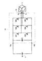
- FIG. 1 is a view showing an electric motorcycle 100 according to a first embodiment.
- FIG. 2 is a view showing a power conversion unit 30 and a motor 3 in the electric motorcycle 100 according to the first embodiment.
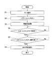
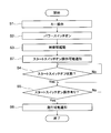
- 5 is a flowchart showing a control method of the electric motorcycle 100 according to the first embodiment. It is a flow chart which shows a control method of electric motorcycle 100 concerning a 2nd embodiment.
- the electric motorcycle 100 is an electric motorcycle such as an electric motorcycle that travels by driving a motor using electric power supplied from a battery. More specifically, the electric motorcycle 100 is a clutchless electric motorcycle in which a motor and wheels are mechanically connected without a clutch.
- the electric motorcycle 100 includes an electric motorcycle control device 1, a first battery 2, a motor 3, a second battery 4, a power switch 5, a start switch 6, and a notification unit 7.
- a wheel 8 and an accelerator position sensor 9 are provided.
- the electric motorcycle control device 1 is a device that controls the electric motorcycle 100, and includes a control unit 10, a storage unit 20, and a power conversion unit 30.
- the electric motorcycle control device 1 may be configured as an ECU (Electronic Control Unit) that controls the entire electric motorcycle 100. Next, each component of the electric motorcycle control device 1 will be described in detail.
- the control unit 10 inputs information from various devices connected to the electric motorcycle control device 1 and controls driving of the motor 3 via the power conversion unit 30. Details of the control unit 10 will be described later.
- the storage unit 20 stores information used by the control unit 10 and a program for the control unit 10 to operate.
- the storage unit 20 is, for example, a non-volatile semiconductor memory, but is not limited to this.
- the power conversion unit 30 converts the DC power of the first battery 2 into AC power and supplies the AC power to the motor 3. As shown in FIG. 2, the power conversion unit 30 is configured of a three-phase full bridge circuit.
- the semiconductor switches Q1, Q3 and Q5 are high side switches, and the semiconductor switches Q2, Q4 and Q6 are low side switches. Control terminals of the semiconductor switches Q1 to Q6 are electrically connected to the control unit 10.
- a smoothing capacitor C is provided between the power supply terminal 30a and the power supply terminal 30b.
- the semiconductor switches Q1 to Q6 are, for example, MOSFETs or IGBTs.
- the semiconductor switch Q1 is connected between the power supply terminal 30a to which the positive electrode of the first battery 2 is connected and the input terminal 3a of the motor 3, as shown in FIG.
- the semiconductor switch Q3 is connected between the power supply terminal 30a and the input terminal 3b of the motor 3.
- the semiconductor switch Q5 is connected between the power supply terminal 30a and the input terminal 3c of the motor 3.
- the semiconductor switch Q2 is connected between the input terminal 3a of the motor 3 and the power supply terminal 30b to which the negative electrode of the first battery 2 is connected.
- the semiconductor switch Q4 is connected between the input terminal 3b of the motor 3 and the power supply terminal 30b.
- the semiconductor switch Q6 is connected between the input terminal 3c of the motor 3 and the power supply terminal 30b.
- the input terminal 3a is a U-phase input terminal
- the input terminal 3b is a V-phase input terminal
- the input terminal 3c is a W-phase input terminal.
- the first battery 2 can be charged and discharged. Specifically, the first battery 2 supplies DC power to the power conversion unit 30 at the time of discharge. The first battery 2 is charged by the power supplied from an external power supply (not shown). Further, the first battery 2 is charged by the DC voltage obtained by converting the AC power output by the motor 3 by the power conversion device 100 during charging by AC power output by the motor 3 along with the rotation of the wheel 8 (ie, regeneration). Be charged).
- the first battery 2 includes a battery management unit (BMU) not shown.
- the battery management unit transmits, to the control unit 10, information on the voltage of the first battery 2 and the state (charging rate etc.) of the first battery 2.
- the number of first batteries 2 is not limited to one, and may be plural.
- the first battery 2 is, for example, a lithium ion battery, but may be another type of battery.
- the first battery 2 may be composed of batteries of different types (eg, lithium ion battery and lead battery).
- the motor 3 outputs a torque for driving the wheel 8 by the power supplied from the first battery 2.
- the motor 3 is driven by the AC power supplied from the power conversion unit 30 to output a torque for driving the wheel 8.
- the torque may be controlled by the control unit 10 outputting, to the semiconductor switches Q1 to Q6 of the power conversion unit 30, a PWM signal having a conduction timing and a duty ratio calculated based on the target torque.
- the motor 3 is mechanically connected to the wheel 8 and causes the wheel 8 to rotate in a desired direction by torque.
- the motor 3 is mechanically connected to the wheel 8 without a clutch.
- the type of motor 3 is not particularly limited.
- the motor 3 outputs AC power (that is, regenerative power) by the reduction of the rotational speed of the motor 3 or the rotation of the motor 3 due to an external force.
- the motor 3 travels on a slope or travels downhill (in a downward slope) with inertia when the vehicle is braked and braked while the vehicle is running, or when the battery 2 does not supply power to the motor 3 In the case, it outputs AC power.
- the AC power output from the motor 3 is converted into DC power by the power conversion unit 30, and the first battery 2 is charged (that is, regeneratively charged) with the converted DC power.
- the second battery 4 can be charged and discharged.
- the second battery 4 is used to start the control unit 10 and drive the notification unit 7 or the like.
- the second battery 4 may be a battery having a smaller capacity than the first battery 2.
- the second battery 4 may be, for example, a lead battery.
- One end of the power switch 5 is connected to the second battery 4.
- the power switch 5 is turned on or off in response to a key operation by the user.
- the start switch 6 is turned on or off according to the user operation.
- the notification unit 7 notifies the user that the vehicle can travel.
- the accelerator position sensor 9 detects an accelerator operation amount set by the user's accelerator operation, and transmits the detected accelerator operation amount to the control unit 10 as an electric signal. When the user wants to accelerate, the accelerator operation amount becomes large.
- control unit 10 and the notification unit 7 of the electric motorcycle control device 1 will be described in detail.
- the control unit 10 is connected to the first battery 2, the motor 3, the other end of the power switch 5, the start switch 6, and the notification unit 7.
- the control unit 10 is activated by the power supplied from the second battery 4 when the power switch 5 is turned on.
- control unit 10 performs control to supply power from the first battery 2 to the motor 3 when the start switch 6 is turned on after start-up, and notifies that the vehicle can travel.
- Control 7
- control unit 10 detects both the off state of the start switch 6 and the on state of the start switch 6 after the off state after the start-up, the electric power is supplied from the first battery 2 to the motor 3 Control is performed to notify the supply control and notification unit 7 that the vehicle can travel.
- the control unit 10 does not start up without being supplied with power from the second battery 4.
- not starting up also includes the case where the control unit 10 changes from the starting state to the stopping state.
- the control unit 10 does not start, the control unit 10 does not perform control for supplying power from the first battery 2 to the motor 3 and control for notifying the notification unit 7 that the vehicle can travel.
- the notification unit 7 notifies that the vehicle can travel by voice output and image display.
- the notification unit 7 includes a power switch control unit 71, a buzzer 72, and a meter 73.
- the power switch control unit 71 and the meter 73 are directly connected to the second battery 4 and are driven by the power supplied from the second battery 4.
- the power switch control unit 71 performs control to turn on or off the power switch 5 in accordance with the user's key operation. For example, when a user carrying a key having a wireless communication function with the power switch control unit 71 approaches the electric motorcycle 100, the power switch control unit 71 turns on the power switch 5 when the key is authenticated. On the other hand, the power switch control unit 71 turns off the power switch 5 when the user carrying the key does not authenticate the key by moving away from the electric motorcycle 100 or the like.
- the buzzer 72 is connected to the power switch control unit 71.
- the buzzer 72 is controlled by the power switch control unit 71 to output sound.
- the control unit 10 controls the notification unit 7 by instructing the power switch control unit 71 that the vehicle can travel when the start switch 6 is turned on.
- the power switch control unit 71 notifies that the vehicle can travel by causing the buzzer 72 to output a voice according to an instruction of the control unit 10.
- the control unit 10 causes the meter 73 to display an image indicating that the vehicle can travel, thereby notifying that the vehicle can travel.
- the image may be, for example, an image of a mark indicating that the vehicle can travel.
- the meter 73 is a display (for example, a liquid crystal panel) provided on the electric motorcycle 100, and displays various information. Specifically, information such as the traveling speed of the electric motorcycle 100, the remaining amount of the first battery 2, the current time, and the traveling distance is displayed on the meter 7. In the present embodiment, the meter 7 is provided on a handle (not shown) of the electric motorcycle 100.
- the notification unit 7 may include a vibration generating device, and when the start switch 6 is turned on, the notification unit 7 may notify that the vehicle can travel by generation of vibration.
- the power switch control unit 71 may control the operation of the vibration generating device.
- This key operation may be, for example, an operation in which the user carrying the key approaches the electric motorcycle 100.
- the power switch control unit 71 turns on the power switch 5 (step S2).
- step S3 When the power switch 5 is turned on, power is supplied from the second battery 4 to the control unit 10, and the control unit 10 is started by the supplied power (step S3).
- control unit 10 determines whether the start switch 6 is in the off state (step S4).
- step S4 Yes
- the control unit 10 determines whether the start switch 6 is turned on (step S5).
- step S4 No
- the control unit 10 repeatedly determines whether the start switch 6 is in the off state (step S4).
- step S5 When the start switch 6 is turned on (step S5: Yes), the control unit 10 controls the notification unit 7 to notify that the vehicle can travel. Thereby, the notification unit 7 notifies that the vehicle can travel (step S6). Specifically, the notification unit 7 notifies that the vehicle can travel by sound output by the buzzer 72 and image display by the meter 73.
- step S5 when the start switch 6 is not turned on (step S5: No), the control unit 10 repeats the determination as to whether the start switch 6 is turned on (step S5).
- the control unit 10 controls the supply of power from the first battery 2 to the motor 3 to notify the notification unit 7 that the vehicle can travel. It can be done.
- the user can easily determine that the vehicle can be driven by the execution of the two actions of the key operation and the turning on of the start switch.
- the vehicle travels.
- the notification unit 7 is controlled to notify that it is possible.
- the user can know that the vehicle can not travel even if the power switch 5 is turned on while the start switch 6 is turned on.
- the notification unit 7 notifies that the vehicle can travel by voice output.
- the user can easily determine that the vehicle can be driven through hearing in the electric motorcycle 100 powered by the motor 3 which is different from the engine and whose driving state is difficult to determine.
- the notification unit 7 is driven by the power supplied from the second battery 4 and performs control to turn on or off the power switch 5 in accordance with the user's key operation.
- a power switch control unit 71 and a buzzer 72 controlled by the power switch control unit 71 to output sound are included.
- the control unit 10 controls the notification unit 7 by instructing the power switch control unit 71 that the vehicle can travel when the start switch 6 is turned on, and the power switch control unit 71 By outputting a sound to the buzzer 72 in accordance with an instruction from the control unit 10, it is notified that the vehicle can travel.
- the power switch control unit 71 can control both the on / off of the power switch 5 and the audio output of the buzzer 72 for notifying that the vehicle can travel.
- the notification unit 7 notifies that the vehicle can travel by image display.
- the user can easily judge through vision that the vehicle can be driven in the electric two-wheeled vehicle 100 powered by the motor 3 which is difficult to determine the driving state unlike the engine.
- the notification unit 7 may notify that the vehicle can travel by the occurrence of vibration.
- the user can easily determine that the vehicle can be driven through sensation in the electric motorcycle 100 powered by the motor 3 which is different from the engine and in which it is difficult to determine the driving state.
- the notification unit 7 further notifies the user that a user operation to turn on the start switch 6 is possible.
- the notification unit 7 notifies the user that the user operation of turning on the start switch 6 is possible.
- the notification unit 7 notifies that the user operation to turn on the start switch 6 is possible by the audio output by the buzzer 72 and the image display by the meter 73.
- the notification unit 7 may notify that the user operation to turn on the start switch 6 is possible by the occurrence of the vibration.
- the image and the sound for notifying that the user operation to turn on the start switch 6 is possible may be different from the image and the sound for notifying that the vehicle can travel. As a result, the user can easily determine whether the user operation to turn on the start switch 6 is notified or the vehicle can be traveled.
- the image and the sound for notifying that the user operation to turn on the start switch 6 is possible may be the same as the image and the sound for notifying that the vehicle can travel.
- the voice and the image can be shared in the case of notifying that the user operation to turn on the start switch 6 is possible and in the case of notifying that the vehicle can travel, cost can be reduced. it can.
- the user determines that the user operation to turn on the start switch 6 is possible by the first audio output and image display, and the vehicle can travel by the second audio output and image display. It can be determined that
- the power switch control unit 71 When the power switch control unit 71 turns on the power switch 5 to activate the control unit 10, the user operates the start switch 6 to turn on the start switch 6 by causing the buzzer 72 to output a voice under the control of the control unit 10. It may notify that it is possible.
- the power switch control unit 71 authenticates the key operation to turn on the power switch 5 and turns on the power switch 5, the buzzer 72 is processed as a process unique to the power switch control unit 71 without waiting for activation of the control unit 10. By outputting an audio to the user, it may be promptly notified that the user operation to turn on the start switch 6 is possible.
- the notification unit 7 turns on the start switch 6 by sound output by the buzzer 72 and image display by the meter 73 after the power switch 5 is turned on (step S2). It notifies that the user operation is possible (step S7).
- the notification unit 7 notifies that the user operation to turn on the start switch 6 is possible after activation of the control unit 10 by turning on the power switch 5.
- steps S4 to S6 After notifying that the user operation to turn on the start switch 6 is possible, steps (steps S4 to S6) after the determination of the off state of the start switch 6 (step S4) are performed as in the first embodiment. Run.
- the notification unit 7 is notified that the user operation to turn on the start switch 6 is possible. be able to.
- the user can easily determine that the user can turn on the start switch 6.
- the notification unit 7 notifies by voice output that the user operation to turn on the start switch 6 is possible.
- the notification unit 7 notifies that the user operation to turn on the start switch 6 has become possible by image display.
- the user can easily judge that the user operation to turn on the start switch 6 has become possible through visual inspection.
- the notification unit 7 may notify that the user operation to turn on the start switch 6 has become possible due to the occurrence of vibration.
- At least a part of the electric motorcycle control device 1 (control unit 10) described in the above-described embodiment may be configured by hardware or may be configured by software.
- a program for realizing at least a part of the functions of the control unit 10 may be stored in a recording medium such as a flexible disk or a CD-ROM, read by a computer, and executed.
- the recording medium is not limited to a removable medium such as a magnetic disk or an optical disk, and may be a fixed recording medium such as a hard disk drive or a memory.
- a program for realizing at least a part of the functions of the control unit 10 may be distributed via a communication line (including wireless communication) such as the Internet.
- the program may be encrypted, modulated, compressed, or stored in a recording medium via a wired line or a wireless line such as the Internet or may be distributed.
- control device 1 electric motorcycle control device 2 first battery 3 motor 4 second battery 5 power switch 6 start switch 7 notification unit 10 control unit 100 electric motorcycle
Landscapes
- Engineering & Computer Science (AREA)
- Chemical & Material Sciences (AREA)
- Combustion & Propulsion (AREA)
- Transportation (AREA)
- Mechanical Engineering (AREA)
- Electric Propulsion And Braking For Vehicles (AREA)
- Charge And Discharge Circuits For Batteries Or The Like (AREA)
Abstract
充放電可能な第1バッテリおよび第2バッテリと、第1バッテリから供給された電力によって車輪を駆動するためのトルクを出力するモータと、一端が第2バッテリに接続され、ユーザのキー操作に応じてオンまたはオフするパワースイッチと、ユーザ操作に応じてオンまたはオフするスタートスイッチと、ユーザに車両が走行可能であることを通知する通知部と、第1バッテリ、モータ、パワースイッチの他端、スタートスイッチおよび通知部に接続された制御部と、を備え、制御部は、パワースイッチがオンしたときに、第2バッテリから供給された電力によって起動し、起動後にスタートスイッチがオンしたときに、第1バッテリからモータに電力を供給する制御を行い且つ車両が走行可能であることを通知するように通知部を制御し、一方、パワースイッチがオフしたときに、第2バッテリから電力が供給されない。
Description
本発明は、電動二輪車、電動二輪車制御装置および電動二輪車制御方法に関する。
電動二輪車は、エンジン車と同様に、キー操作とスタートスイッチのオンとの2アクションが実行された場合に走行可能となるように法規で定められている。
しかしながら、電動二輪車は、駆動状態を音や振動で判断し易いエンジンとは異なり、駆動状態が静かなモータを動力とするため、ユーザは、電動二輪車がモータの音や振動で走行可能な状態となったか否かを判断することが困難である。
このため、従来は、2アクションの実行によって車両が走行可能な状態になったことをユーザが容易に判断することができないといった問題があった。
なお、特開2016-199084号公報には、駆動待機状態を使用者に報知する報知ユニットを含む電動車両が開示されている。しかし、特開2016-199084号公報における駆動待機状態の報知は、アシスト状態において自走スイッチが操作された場合に行われるため、2アクションの実行とは無関係である。
そこで、本発明は、キー操作とスタートスイッチのオンとの2アクションの実行によって車両が走行可能な状態となったことをユーザが容易に判断することが可能な電動二輪車、電動二輪車制御装置および電動二輪車制御方法を提供することを目的とする。
本発明の一態様に係る電動二輪車は、
充放電可能な第1バッテリおよび第2バッテリと、
前記第1バッテリから供給された電力によって車輪を駆動するためのトルクを出力するモータと、
一端が前記第2バッテリに接続され、ユーザのキー操作に応じてオンまたはオフするパワースイッチと、
ユーザ操作に応じてオンまたはオフするスタートスイッチと、
ユーザに車両が走行可能であることを通知する通知部と、
前記第1バッテリ、前記モータ、前記パワースイッチの他端、前記スタートスイッチおよび前記通知部に接続された制御部と、を備え、
前記制御部は、前記パワースイッチがオンしたときに、前記第2バッテリから供給された電力によって起動し、起動後に前記スタートスイッチがオンしたときに、前記第1バッテリから前記モータに電力を供給する制御を行い且つ前記車両が走行可能であることを通知するように前記通知部を制御し、一方、前記パワースイッチがオフしたときに、前記第2バッテリから電力が供給されない。
充放電可能な第1バッテリおよび第2バッテリと、
前記第1バッテリから供給された電力によって車輪を駆動するためのトルクを出力するモータと、
一端が前記第2バッテリに接続され、ユーザのキー操作に応じてオンまたはオフするパワースイッチと、
ユーザ操作に応じてオンまたはオフするスタートスイッチと、
ユーザに車両が走行可能であることを通知する通知部と、
前記第1バッテリ、前記モータ、前記パワースイッチの他端、前記スタートスイッチおよび前記通知部に接続された制御部と、を備え、
前記制御部は、前記パワースイッチがオンしたときに、前記第2バッテリから供給された電力によって起動し、起動後に前記スタートスイッチがオンしたときに、前記第1バッテリから前記モータに電力を供給する制御を行い且つ前記車両が走行可能であることを通知するように前記通知部を制御し、一方、前記パワースイッチがオフしたときに、前記第2バッテリから電力が供給されない。
また、前記電動二輪車において、
前記制御部は、前記スタートスイッチのオフ状態と、前記オフ状態の後の前記スタートスイッチのオン状態との双方を検知したときに、前記車両が走行可能であることを通知するように前記通知部を制御してもよい。
前記制御部は、前記スタートスイッチのオフ状態と、前記オフ状態の後の前記スタートスイッチのオン状態との双方を検知したときに、前記車両が走行可能であることを通知するように前記通知部を制御してもよい。
また、前記電動二輪車において、
前記通知部は、音声出力によって前記車両が走行可能であることを通知してもよい。
前記通知部は、音声出力によって前記車両が走行可能であることを通知してもよい。
また、前記電動二輪車において、
前記通知部は、
前記第2バッテリから供給される電力で駆動され、前記キー操作に応じて前記パワースイッチをオンまたはオフする制御を行うパワースイッチ制御部と、
前記パワースイッチ制御部により制御され、音声を出力するブザーと、を有し、
前記制御部は、前記スタートスイッチがオンしたときに、前記パワースイッチ制御部に前記車両が走行可能であることの通知を指示することで、前記通知部を制御し、
前記パワースイッチ制御部は、前記指示に応じて前記ブザーに音声を出力させることで、前記車両が走行可能であることを通知してもよい。
前記通知部は、
前記第2バッテリから供給される電力で駆動され、前記キー操作に応じて前記パワースイッチをオンまたはオフする制御を行うパワースイッチ制御部と、
前記パワースイッチ制御部により制御され、音声を出力するブザーと、を有し、
前記制御部は、前記スタートスイッチがオンしたときに、前記パワースイッチ制御部に前記車両が走行可能であることの通知を指示することで、前記通知部を制御し、
前記パワースイッチ制御部は、前記指示に応じて前記ブザーに音声を出力させることで、前記車両が走行可能であることを通知してもよい。
また、前記電動二輪車において、
前記通知部は、画像表示によって前記車両が走行可能であることを通知してもよい。
前記通知部は、画像表示によって前記車両が走行可能であることを通知してもよい。
また、前記電動二輪車において、
前記通知部は、振動の発生によって前記車両が走行可能であることを通知してもよい。
前記通知部は、振動の発生によって前記車両が走行可能であることを通知してもよい。
また、前記電動二輪車において、
前記通知部は、前記パワースイッチがオンしたときに、ユーザに前記スタートスイッチをオンするユーザ操作が可能であることを通知してもよい。
前記通知部は、前記パワースイッチがオンしたときに、ユーザに前記スタートスイッチをオンするユーザ操作が可能であることを通知してもよい。
また、前記電動二輪車において、
前記通知部は、音声出力によって前記スタートスイッチをオンするユーザ操作が可能であることを通知してもよい。
前記通知部は、音声出力によって前記スタートスイッチをオンするユーザ操作が可能であることを通知してもよい。
また、前記電動二輪車において、
前記通知部は、
前記第2バッテリから供給される電力で駆動され、前記キー操作に応じて前記パワースイッチをオンまたはオフする制御を行うパワースイッチ制御部と、
前記パワースイッチ制御部により制御され、音声を出力するブザーと、を有してもよい。
前記通知部は、
前記第2バッテリから供給される電力で駆動され、前記キー操作に応じて前記パワースイッチをオンまたはオフする制御を行うパワースイッチ制御部と、
前記パワースイッチ制御部により制御され、音声を出力するブザーと、を有してもよい。
また、前記電動二輪車において、
前記通知部は、画像表示によって前記スタートスイッチをオンするユーザ操作が可能であることを通知してもよい。
前記通知部は、画像表示によって前記スタートスイッチをオンするユーザ操作が可能であることを通知してもよい。
また、前記電動二輪車において、
前記通知部は、振動の発生によって前記スタートスイッチをオンするユーザ操作が可能であることを通知してもよい。
前記通知部は、振動の発生によって前記スタートスイッチをオンするユーザ操作が可能であることを通知してもよい。
また、前記電動二輪車において、
前記車輪と前記モータとがクラッチを介さずに機械的に接続されていてもよい。
前記車輪と前記モータとがクラッチを介さずに機械的に接続されていてもよい。
本発明の一態様に係る電動二輪車制御装置は、
充放電可能な第1バッテリおよび第2バッテリと、
前記第1バッテリから供給された電力によって車輪を駆動するためのトルクを出力するモータと、
一端が前記第2バッテリに接続され、ユーザのキー操作に応じてオンまたはオフするパワースイッチと、
ユーザ操作に応じてオンまたはオフするスタートスイッチと、
ユーザに車両が走行可能であることを通知する通知部と、を備える電動二輪車を制御する電動二輪車制御装置であって、
前記第1バッテリ、前記モータ、前記パワースイッチの他端、前記スタートスイッチおよび前記通知部に接続された制御部を備え、
前記制御部は、前記パワースイッチがオンしたときに、前記第2バッテリから供給された電力によって起動し、起動後に前記スタートスイッチがオンしたときに、前記第1バッテリから前記モータに電力を供給する制御を行い且つ前記車両が走行可能であることを通知するように前記通知部を制御し、一方、前記パワースイッチがオフしたときに、前記第2バッテリから電力が供給されない。
充放電可能な第1バッテリおよび第2バッテリと、
前記第1バッテリから供給された電力によって車輪を駆動するためのトルクを出力するモータと、
一端が前記第2バッテリに接続され、ユーザのキー操作に応じてオンまたはオフするパワースイッチと、
ユーザ操作に応じてオンまたはオフするスタートスイッチと、
ユーザに車両が走行可能であることを通知する通知部と、を備える電動二輪車を制御する電動二輪車制御装置であって、
前記第1バッテリ、前記モータ、前記パワースイッチの他端、前記スタートスイッチおよび前記通知部に接続された制御部を備え、
前記制御部は、前記パワースイッチがオンしたときに、前記第2バッテリから供給された電力によって起動し、起動後に前記スタートスイッチがオンしたときに、前記第1バッテリから前記モータに電力を供給する制御を行い且つ前記車両が走行可能であることを通知するように前記通知部を制御し、一方、前記パワースイッチがオフしたときに、前記第2バッテリから電力が供給されない。
本発明の一態様に係る電動二輪車制御方法は、
充放電可能な第1バッテリおよび第2バッテリと、
前記第1バッテリから供給された電力によって車輪を駆動するためのトルクを出力するモータと、
一端が前記第2バッテリに接続され、キー操作に応じてオンまたはオフするパワースイッチと、
ユーザ操作に応じてオンまたはオフするスタートスイッチと、
ユーザに車両が走行可能であることを通知する通知部と、を備える電動二輪車を制御する電動二輪車制御方法であって、
前記パワースイッチがオンした後に前記スタートスイッチがオンしたときに、前記第1バッテリから前記モータに電力を供給する制御を行い且つ前記車両が走行可能であることを通知するように前記通知部を制御する。
充放電可能な第1バッテリおよび第2バッテリと、
前記第1バッテリから供給された電力によって車輪を駆動するためのトルクを出力するモータと、
一端が前記第2バッテリに接続され、キー操作に応じてオンまたはオフするパワースイッチと、
ユーザ操作に応じてオンまたはオフするスタートスイッチと、
ユーザに車両が走行可能であることを通知する通知部と、を備える電動二輪車を制御する電動二輪車制御方法であって、
前記パワースイッチがオンした後に前記スタートスイッチがオンしたときに、前記第1バッテリから前記モータに電力を供給する制御を行い且つ前記車両が走行可能であることを通知するように前記通知部を制御する。
本発明の一態様に係る電動二輪車は、充放電可能な第1バッテリおよび第2バッテリと、第1バッテリから供給された電力によって車輪を駆動するためのトルクを出力するモータと、一端が第2バッテリに接続され、ユーザのキー操作に応じてオンまたはオフするパワースイッチと、ユーザ操作に応じてオンまたはオフするスタートスイッチと、ユーザに車両が走行可能であることを通知する通知部と、第1バッテリ、モータ、パワースイッチの他端、スタートスイッチおよび通知部に接続された制御部と、を備え、制御部は、パワースイッチがオンしたときに、第2バッテリから供給された電力によって起動し、起動後にスタートスイッチがオンしたときに、第1バッテリからモータに電力を供給する制御を行い且つ車両が走行可能であることを通知するように通知部を制御し、一方、パワースイッチがオフしたときに、第2バッテリから電力が供給されない。
このように、本発明によれば、ユーザのキー操作に応じたパワースイッチのオンにより、第2バッテリから制御部に電力を供給して制御部を起動し、制御部の起動後におけるユーザ操作に応じたスタートスイッチのオンにより、制御部に第1バッテリからモータへの電力の供給を制御させ、通知部に車両が走行可能であることをユーザに通知させることができる。
これにより、キー操作とスタートスイッチのオンとの2アクションの実行によって車両が走行可能な状態となったことをユーザが容易に判断することが可能となる。
以下、図面を参照して本発明に係る実施形態を説明する。なお、以下に示す実施形態は、本発明を限定するものではない。また、実施形態で参照する図面において、同一部分または同様な機能を有する部分には同一の符号または類似の符号を付し、その繰り返しの説明は省略する。
(第1の実施形態)
まず、図1を参照して、第1の実施形態に係る電動二輪車100について説明する。
まず、図1を参照して、第1の実施形態に係る電動二輪車100について説明する。
電動二輪車100は、バッテリから供給される電力を用いてモータを駆動することで走行する電動バイク等の電動二輪車である。より詳しくは、電動二輪車100は、モータと車輪がクラッチを介さずに機械的に接続されたクラッチレスの電動二輪車である。
電動二輪車100は、図1に示すように、電動二輪車制御装置1と、第1バッテリ2と、モータ3と、第2バッテリ4と、パワースイッチ5と、スタートスイッチ6と、通知部7と、車輪8と、アクセルポジションセンサ9とを備える。
以下、電動二輪車100の各構成要素について詳しく説明する。
電動二輪車制御装置1は、電動二輪車100を制御する装置であり、制御部10と、記憶部20と、電力変換部30とを有している。なお、電動二輪車制御装置1は、電動二輪車100全体を統御するECU(Electronic Control Unit)として構成されてもよい。次に、電動二輪車制御装置1の各構成要素について詳しく説明する。
制御部10は、電動二輪車制御装置1に接続された各種装置から情報を入力するとともに、電力変換部30を介してモータ3を駆動制御する。制御部10の詳細については後述する。
記憶部20は、制御部10が用いる情報や、制御部10が動作するためのプログラムを記憶する。この記憶部20は、例えば不揮発性の半導体メモリであるが、これに限定されない。
電力変換部30は、第1バッテリ2の直流電力を交流電力に変換してモータ3に供給する。この電力変換部30は、図2に示すように、3相のフルブリッジ回路で構成されている。半導体スイッチQ1,Q3,Q5はハイサイドスイッチであり、半導体スイッチQ2,Q4,Q6はローサイドスイッチである。半導体スイッチQ1~Q6の制御端子は、制御部10に電気的に接続されている。電源端子30aと電源端子30bとの間には平滑コンデンサCが設けられている。半導体スイッチQ1~Q6は、例えばMOSFETまたはIGBT等である。
半導体スイッチQ1は、図2に示すように、第1バッテリ2の正極が接続された電源端子30aと、モータ3の入力端子3aとの間に接続されている。同様に、半導体スイッチQ3は、電源端子30aと、モータ3の入力端子3bとの間に接続されている。半導体スイッチQ5は、電源端子30aと、モータ3の入力端子3cとの間に接続されている。
半導体スイッチQ2は、モータ3の入力端子3aと、第1バッテリ2の負極が接続された電源端子30bとの間に接続されている。同様に、半導体スイッチQ4は、モータ3の入力端子3bと、電源端子30bとの間に接続されている。半導体スイッチQ6は、モータ3の入力端子3cと、電源端子30bとの間に接続されている。なお、入力端子3aはU相の入力端子であり、入力端子3bはV相の入力端子であり、入力端子3cはW相の入力端子である。
第1バッテリ2は、充放電可能である。具体的には、第1バッテリ2は、放電時に電力変換部30に直流電力を供給する。また、第1バッテリ2は、図示しない外部電源から供給された電力によって充電される。また、第1バッテリ2には、車輪8の回転にともなってモータ3が出力する交流電力による充電時に、モータ3が出力した交流電力を電力変換装置100で変換した直流電圧によって充電(すなわち、回生充電)される。
この第1バッテリ2は、図示しないバッテリ管理ユニット(BMU)を含む。バッテリ管理ユニットは、第1バッテリ2の電圧や第1バッテリ2の状態(充電率等)に関する情報を制御部10に送信する。
なお、第1バッテリ2の数は一つに限らず、複数であってもよい。第1バッテリ2は、例えばリチウムイオン電池であるが、他の種類のバッテリであってもよい。第1バッテリ2は、異なる種類(例えば、リチウムイオン電池と鉛電池)のバッテリから構成されてもよい。
モータ3は、第1バッテリ2から供給された電力によって車輪8を駆動するためのトルクを出力する。
具体的には、モータ3は、電力変換部30から供給される交流電力により駆動されることで、車輪8を駆動するためのトルクを出力する。トルクは、制御部10が電力変換部30の半導体スイッチQ1~Q6に目標トルクに基づいて算出された通電タイミングとデューティ比を有するPWM信号を出力することで制御されてもよい。モータ3は、車輪8に機械的に接続されており、トルクによって所望の方向に車輪8を回転させる。本実施形態では、モータ3は、クラッチを介さずに車輪8に機械的に接続されている。なお、モータ3の種類は特に限定されない。
また、モータ3は、モータ3の回転速度の減速または外力によるモータ3の回転によって交流電力(すなわち、回生電力)を出力する。例えば、モータ3は、車両の走行中にブレーキがかけられて制動された場合や、バッテリ2からモータ3に電力が供給されていない状態において慣性で走行または坂道(下り坂)を走行している場合に、交流電力を出力する。モータ3が出力した交流電力は、電力変換部30によって直流電力に変換され、変換された直流電力で第1バッテリ2が充電(すなわち、回生充電)される。
第2バッテリ4は、充放電可能である。第2バッテリ4は、制御部10の起動および通知部7の駆動等に用いられる。第2バッテリ4は、第1バッテリ2よりも容量が小さいバッテリであってもよい。第2バッテリ4は、例えば、鉛電池であってもよい。
パワースイッチ5は、一端が第2バッテリ4に接続されている。パワースイッチ5は、ユーザによるキー操作に応じてオンまたはオフする。
スタートスイッチ6は、ユーザ操作に応じてオンまたはオフする。
通知部7は、ユーザに車両が走行可能であることを通知する。
アクセルポジションセンサ9は、ユーザのアクセル操作により設定されたアクセル操作量を検知し、検知されたアクセル操作量を電気信号として制御部10に送信する。ユーザが加速したい場合に、アクセル操作量は大きくなる。
次に、電動二輪車制御装置1の制御部10および通知部7について詳しく説明する。
制御部10は、第1バッテリ2、モータ3、パワースイッチ5の他端、スタートスイッチ6および通知部7に接続されている。
制御部10は、パワースイッチ5がオンしたときに、第2バッテリ4から供給された電力によって起動する。
また、制御部10は、起動後にスタートスイッチ6がオンしたときに、第1バッテリ2からモータ3に電力を供給する制御を行い、かつ、車両が走行可能であることを通知するように通知部7を制御する。
より具体的には、制御部10は、起動後にスタートスイッチ6のオフ状態とオフ状態の後のスタートスイッチ6のオン状態との双方を検知したときに、第1バッテリ2からモータ3に電力を供給する制御および通知部7に車両が走行可能であることを通知させる制御を行う。
一方、制御部10は、パワースイッチ5がオフしたときに、第2バッテリ4から電力が供給されずに起動しない。ここで、起動しないとは、制御部10が起動状態から停止状態になる場合も含む。制御部10が起動しない場合、制御部10は、第1バッテリ2からモータ3に電力を供給する制御および通知部7に車両が走行可能であることを通知させる制御を行わない。
通知部7は、音声出力および画像表示によって車両が走行可能であることを通知する。
具体的には、図1に示すように、通知部7は、パワースイッチ制御部71と、ブザー72と、メータ73とを有する。
パワースイッチ制御部71およびメータ73は、第2バッテリ4に直接接続されており、第2バッテリ4から供給される電力で駆動される。
パワースイッチ制御部71は、ユーザのキー操作に応じてパワースイッチ5をオンまたはオフする制御を行う。例えば、パワースイッチ制御部71は、パワースイッチ制御部71との無線通信機能を有するキーを携帯するユーザが電動二輪車100に近づくことによってキーが認証された場合に、パワースイッチ5をオンする。一方、パワースイッチ制御部71は、キーを携帯するユーザが電動二輪車100から遠ざかること等によってキーが認証されない場合には、パワースイッチ5をオフする。
ブザー72は、パワースイッチ制御部71に接続されている。ブザー72は、パワースイッチ制御部71により制御されて、音声を出力する。
制御部10は、スタートスイッチ6がオンしたときに、パワースイッチ制御部71に車両が走行可能であることの通知を指示することで、通知部7を制御する。
パワースイッチ制御部71は、制御部10の指示に応じてブザー72に音声を出力させることで、車両が走行可能であることを通知する。
また、制御部10は、スタートスイッチ6がオンしたときに、メータ73に車両が走行可能であることを示す画像を表示させることで、車両が走行可能であることを通知させる。画像は、例えば、車両が走行可能であることを示すマークの画像であってもよい。なお、メータ73は、電動二輪車100に設けられたディスプレイ(例えば液晶パネル)であり、各種情報を表示する。具体的には、電動二輪車100の走行速度、第1バッテリ2の残量、現在時刻、走行距離などの情報がメータ7に表示される。本実施形態では、メータ7は、電動二輪車100のハンドル(図示せず)に設けられる。
なお、通知部7は、振動発生装置を備え、スタートスイッチ6がオンしたときに、振動の発生によって車両が走行可能であることを通知してもよい。この場合、振動発生装置の動作は、パワースイッチ制御部71が制御してもよい。
(電動二輪車制御方法)
以下、図3のフローチャートを参照して、第1の実施形態に係る電動二輪車制御方法について説明する。なお、図3のフローチャートは、必要に応じて繰り返される。
以下、図3のフローチャートを参照して、第1の実施形態に係る電動二輪車制御方法について説明する。なお、図3のフローチャートは、必要に応じて繰り返される。
先ず、ユーザが、パワースイッチ5をオンするためのキー操作を行う(ステップS1)。このキー操作は、例えば、キーを携帯したユーザが電動二輪車100に近づく動作であってもよい。
パワースイッチ5をオンするためのキー操作が行われることで、パワースイッチ制御部71は、パワースイッチ5をオンする(ステップS2)。
パワースイッチ5がオンされることで、第2バッテリ4から制御部10に電力が供給され、供給された電力によって制御部10が起動する(ステップS3)。
起動した後、制御部10は、スタートスイッチ6がオフ状態であるか否かを判定する(ステップS4)。スタートスイッチ6がオフ状態である場合(ステップS4:Yes)、制御部10は、スタートスイッチ6がオン操作されたか否かを判定する(ステップS5)。一方、スタートスイッチ6がオフ状態でない場合(ステップS4:No)、制御部10は、スタートスイッチ6がオフ状態であるか否かの判定を繰り返す(ステップS4)。
スタートスイッチ6がオン操作された場合(ステップS5:Yes)、制御部10は、車両が走行可能であることを通知するように通知部7を制御する。これにより、通知部7は、車両が走行可能であることを通知する(ステップS6)。具体的には、通知部7は、ブザー72による音声出力およびメータ73による画像表示によって、車両が走行可能であることを通知する。一方、スタートスイッチ6がオン操作されていない場合(ステップS5:No)、制御部10は、スタートスイッチ6がオン操作されたか否かの判定を繰り返す(ステップS5)。
以下、第1の実施形態によってもたらされる作用について説明する。
上述したように、第1の実施形態においては、ユーザのキー操作に応じたパワースイッチ5のオンにより、第2バッテリ4から制御部10に電力を供給して制御部10を起動し、制御部10の起動後におけるユーザ操作に応じたスタートスイッチ6のオンにより、制御部10に第1バッテリ2からモータ3への電力の供給を制御させ、通知部7に車両が走行可能であることを通知させることができる。
これにより、キー操作とスタートスイッチのオンとの2アクションの実行によって車両が走行可能な状態となったことをユーザが容易に判断することが可能となる。
また、上述したように、第1の実施形態において、制御部10は、スタートスイッチ6のオフ状態と、オフ状態の後のスタートスイッチ6のオン状態との双方を検知したときに、車両が走行可能であることを通知するように通知部7を制御する。
これにより、スタートスイッチ6をオンしたままパワースイッチ5をオンしても車両が走行可能とならないことをユーザに把握させることができる。
また、上述したように、第1の実施形態において、通知部7は、音声出力によって車両が走行可能であることを通知する。
これにより、ユーザは、エンジンとは異なり駆動状態を判断し難いモータ3を動力とした電動二輪車100において、聴覚を通じて車両が走行可能な状態となったことを容易に判断することができる。
また、上述したように、第1の実施形態において、通知部7は、第2バッテリ4から供給される電力で駆動され、ユーザのキー操作に応じてパワースイッチ5をオンまたはオフする制御を行うパワースイッチ制御部71と、パワースイッチ制御部71により制御され、音声を出力するブザー72とを有する。そして、制御部10は、スタートスイッチ6がオンしたときに、パワースイッチ制御部71に車両が走行可能であることの通知を指示することで通知部7を制御し、パワースイッチ制御部71は、制御部10の指示に応じてブザー72に音声を出力させることで車両が走行可能であることを通知する。
これにより、パワースイッチ制御部71によって、パワースイッチ5のオンオフと、車両が走行可能であることを通知するためのブザー72の音声出力との双方を制御することができる。
また、上述したように、第1の実施形態において、通知部7は、画像表示によって車両が走行可能であることを通知する。
これにより、ユーザは、エンジンとは異なり駆動状態を判断し難いモータ3を動力とした電動二輪車100において、視覚を通じて車両が走行可能な状態となったことを容易に判断することができる。
また、上述したように、第1の実施形態において、通知部7は、振動の発生によって車両が走行可能であることを通知してもよい。
これにより、ユーザは、エンジンとは異なり駆動状態を判断し難いモータ3を動力とした電動二輪車100において、感覚を通じて車両が走行可能な状態となったことを容易に判断することができる。
(第2の実施形態)
次に、図4を参照して、第2の実施形態に係る電動二輪車100について説明する。第2の実施形態に係る電動二輪車100は、第1の実施形態の構成に加えて、更に、通知部7が、ユーザにスタートスイッチ6をオンするユーザ操作が可能であることを通知する。
次に、図4を参照して、第2の実施形態に係る電動二輪車100について説明する。第2の実施形態に係る電動二輪車100は、第1の実施形態の構成に加えて、更に、通知部7が、ユーザにスタートスイッチ6をオンするユーザ操作が可能であることを通知する。
具体的には、通知部7は、ユーザのキー操作によってパワースイッチ5がオンしたときに、ユーザにスタートスイッチ6をオンするユーザ操作が可能であることを通知する。
具体的には、通知部7は、ブザー72による音声出力およびメータ73による画像表示によって、スタートスイッチ6をオンするユーザ操作が可能であることを通知する。なお、通知部7は、振動の発生によってスタートスイッチ6をオンするユーザ操作が可能であることを通知してもよい。
スタートスイッチ6をオンするユーザ操作が可能であることを通知するための画像および音声は、車両が走行可能であることを通知するための画像および音声と異なっていてもよい。これにより、ユーザは、スタートスイッチ6をオンするユーザ操作が可能であることが通知されたのか、または、車両が走行可能であることが通知されたのかを容易に判断することができる。
あるいは、スタートスイッチ6をオンするユーザ操作が可能であることを通知するための画像および音声は、車両が走行可能であることを通知するための画像および音声と同一であってもよい。これにより、スタートスイッチ6をオンするユーザ操作が可能であることを通知する場合と、車両が走行可能であることを通知する場合とで、音声および画像を共用できるので、コストを削減することができる。また、この場合でも、ユーザは、1回目の音声出力および画像表示によって、スタートスイッチ6をオンするユーザ操作が可能であることを判断し、2回目の音声出力および画像表示によって、車両が走行可能であることを判断することができる。
なお、パワースイッチ制御部71は、パワースイッチ5をオンして制御部10が起動したときに、制御部10の制御によってブザー72に音声を出力させることで、スタートスイッチ6をオンするユーザ操作が可能であることを通知してもよい。あるいは、パワースイッチ制御部71は、パワースイッチ5をオンするキー操作を認証してパワースイッチ5をオンしたときに、制御部10の起動を待たずにパワースイッチ制御部71独自の処理としてブザー72に音声を出力させることで、スタートスイッチ6をオンするユーザ操作が可能であることを迅速に通知してもよい。
以下、図4のフローチャートを参照して、第2の実施形態に係る電動二輪車制御方法について、第1の実施形態との差異を中心に説明する。なお、図4のフローチャートは、必要に応じて繰り返される。
図4に示すように、第2の実施形態において、通知部7は、パワースイッチ5をオンした後(ステップS2)、ブザー72による音声出力およびメータ73による画像表示によって、スタートスイッチ6をオンするユーザ操作が可能であることを通知する(ステップS7)。なお、図4の例において、通知部7は、パワースイッチ5のオンによる制御部10の起動後に、スタートスイッチ6をオンするユーザ操作が可能であることを通知する。
スタートスイッチ6をオンするユーザ操作が可能であることを通知した後は、第1の実施形態と同様に、スタートスイッチ6のオフ状態の判定(ステップS4)以降の工程(ステップS4~S6)を実行する。
上述したように、第2の実施形態によれば、ユーザのキー操作に応じてパワースイッチ5をオンしたときに、通知部7にスタートスイッチ6をオンするユーザ操作が可能であることを通知させることができる。
これにより、スタートスイッチ6をオンするユーザ操作が可能であることをユーザが容易に判断することが可能となる。
また、上述したように、第2の実施形態において、通知部7は、音声出力によってスタートスイッチ6をオンするユーザ操作が可能であることを通知する。
これにより、ユーザは、聴覚を通じてスタートスイッチ6をオンするユーザ操作が可能となったことを容易に判断することができる。
また、上述したように、第2の実施形態において、通知部7は、画像表示によってスタートスイッチ6をオンするユーザ操作が可能となったことを通知する。
これにより、ユーザは、視覚を通じてスタートスイッチ6をオンするユーザ操作が可能となったことを容易に判断することができる。
また、上述したように、第2の実施形態において、通知部7は、振動の発生によってスタートスイッチ6をオンするユーザ操作が可能となったことを通知してもよい。
これにより、ユーザは、感覚を通じてスタートスイッチ6をオンするユーザ操作が可能となったことを容易に判断することができる。
上述した実施形態で説明した電動二輪車制御装置1(制御部10)の少なくとも一部は、ハードウェアで構成してもよいし、ソフトウェアで構成してもよい。ソフトウェアで構成する場合には、制御部10の少なくとも一部の機能を実現するプログラムをフレキシブルディスクやCD-ROM等の記録媒体に収納し、コンピュータに読み込ませて実行させてもよい。記録媒体は、磁気ディスクや光ディスク等の着脱可能なものに限定されず、ハードディスク装置やメモリなどの固定型の記録媒体でもよい。
また、制御部10の少なくとも一部の機能を実現するプログラムを、インターネット等の通信回線(無線通信も含む)を介して頒布してもよい。さらに、同プログラムを暗号化したり、変調をかけたり、圧縮した状態で、インターネット等の有線回線や無線回線を介して、あるいは記録媒体に収納して頒布してもよい。
上記の記載に基づいて、当業者であれば、本発明の追加の効果や種々の変形を想到できるかもしれないが、本発明の態様は、上述した個々の実施形態に限定されるものではない。異なる実施形態にわたる構成要素を適宜組み合わせてもよい。特許請求の範囲に規定された内容及びその均等物から導き出される本発明の概念的な思想と趣旨を逸脱しない範囲で種々の追加、変更及び部分的削除が可能である。
1 電動二輪車制御装置
2 第1バッテリ
3 モータ
4 第2バッテリ
5 パワースイッチ
6 スタートスイッチ
7 通知部
10 制御部
100 電動二輪車
2 第1バッテリ
3 モータ
4 第2バッテリ
5 パワースイッチ
6 スタートスイッチ
7 通知部
10 制御部
100 電動二輪車
Claims (14)
- 充放電可能な第1バッテリおよび第2バッテリと、
前記第1バッテリから供給された電力によって車輪を駆動するためのトルクを出力するモータと、
一端が前記第2バッテリに接続され、ユーザのキー操作に応じてオンまたはオフするパワースイッチと、
ユーザ操作に応じてオンまたはオフするスタートスイッチと、
ユーザに車両が走行可能であることを通知する通知部と、
前記第1バッテリ、前記モータ、前記パワースイッチの他端、前記スタートスイッチおよび前記通知部に接続された制御部と、を備え、
前記制御部は、前記パワースイッチがオンしたときに、前記第2バッテリから供給された電力によって起動し、起動後に前記スタートスイッチがオンしたときに、前記第1バッテリから前記モータに電力を供給する制御を行い且つ前記車両が走行可能であることを通知するように前記通知部を制御し、一方、前記パワースイッチがオフしたときに、前記第2バッテリから電力が供給されないことを特徴とする電動二輪車。 - 前記制御部は、前記スタートスイッチのオフ状態と、前記オフ状態の後の前記スタートスイッチのオン状態との双方を検知したときに、前記車両が走行可能であることを通知するように前記通知部を制御することを特徴とする請求項1に記載の電動二輪車。
- 前記通知部は、音声出力によって前記車両が走行可能であることを通知することを特徴とする請求項1に記載の電動二輪車。
- 前記通知部は、
前記第2バッテリから供給される電力で駆動され、前記キー操作に応じて前記パワースイッチをオンまたはオフする制御を行うパワースイッチ制御部と、
前記パワースイッチ制御部により制御され、音声を出力するブザーと、を有し、
前記制御部は、前記スタートスイッチがオンしたときに、前記パワースイッチ制御部に前記車両が走行可能であることの通知を指示することで、前記通知部を制御し、
前記パワースイッチ制御部は、前記指示に応じて前記ブザーに音声を出力させることで、前記車両が走行可能であることを通知することを特徴とする請求項3に記載の電動二輪車。 - 前記通知部は、画像表示によって前記車両が走行可能であることを通知することを特徴とする請求項1に記載の電動二輪車。
- 前記通知部は、振動の発生によって前記車両が走行可能であることを通知することを特徴とする請求項1に記載の電動二輪車。
- 前記通知部は、前記パワースイッチがオンしたときに、ユーザに前記スタートスイッチをオンするユーザ操作が可能であることを通知することを特徴とする請求項1に記載の電動二輪車。
- 前記通知部は、音声出力によって前記スタートスイッチをオンするユーザ操作が可能であることを通知することを特徴とする請求項7に記載の電動二輪車。
- 前記通知部は、
前記第2バッテリから供給される電力で駆動され、前記キー操作に応じて前記パワースイッチをオンまたはオフする制御を行うパワースイッチ制御部と、
前記パワースイッチ制御部により制御され、音声を出力するブザーと、を有することを特徴とする請求項8に記載の電動二輪車。 - 前記通知部は、画像表示によって前記スタートスイッチをオンするユーザ操作が可能であることを通知することを特徴とする請求項7に記載の電動二輪車。
- 前記通知部は、振動の発生によって前記スタートスイッチをオンするユーザ操作が可能であることを通知することを特徴とする請求項7に記載の電動二輪車。
- 前記車輪と前記モータとがクラッチを介さずに機械的に接続されていることを特徴とする請求項1に記載の電動二輪車。
- 充放電可能な第1バッテリおよび第2バッテリと、
前記第1バッテリから供給された電力によって車輪を駆動するためのトルクを出力するモータと、
一端が前記第2バッテリに接続され、ユーザのキー操作に応じてオンまたはオフするパワースイッチと、
ユーザ操作に応じてオンまたはオフするスタートスイッチと、
ユーザに車両が走行可能であることを通知する通知部と、を備える電動二輪車を制御する電動二輪車制御装置であって、
前記第1バッテリ、前記モータ、前記パワースイッチの他端、前記スタートスイッチおよび前記通知部に接続された制御部を備え、
前記制御部は、前記パワースイッチがオンしたときに、前記第2バッテリから供給された電力によって起動し、起動後に前記スタートスイッチがオンしたときに、前記第1バッテリから前記モータに電力を供給する制御を行い且つ前記車両が走行可能であることを通知するように前記通知部を制御し、一方、前記パワースイッチがオフしたときに、前記第2バッテリから電力が供給されないことを特徴とする電動二輪車制御装置。 - 充放電可能な第1バッテリおよび第2バッテリと、
前記第1バッテリから供給された電力によって車輪を駆動するためのトルクを出力するモータと、
一端が前記第2バッテリに接続され、キー操作に応じてオンまたはオフするパワースイッチと、
ユーザ操作に応じてオンまたはオフするスタートスイッチと、
ユーザに車両が走行可能であることを通知する通知部と、を備える電動二輪車を制御する電動二輪車制御方法であって、
前記パワースイッチがオンした後に前記スタートスイッチがオンしたときに、前記第1バッテリから前記モータに電力を供給する制御を行い且つ前記車両が走行可能であることを通知するように前記通知部を制御することを特徴とする電動二輪車制御方法。
Priority Applications (4)
| Application Number | Priority Date | Filing Date | Title |
|---|---|---|---|
| CN201780094647.7A CN111225819B (zh) | 2017-09-08 | 2017-09-08 | 电动两轮车、电动两轮车控制装置以及电动两轮车控制方法 |
| JP2019540255A JP6776455B2 (ja) | 2017-09-08 | 2017-09-08 | 電動二輪車、電動二輪車制御装置および電動二輪車制御方法 |
| PCT/JP2017/032573 WO2019049335A1 (ja) | 2017-09-08 | 2017-09-08 | 電動二輪車、電動二輪車制御装置および電動二輪車制御方法 |
| TW107129482A TWI716720B (zh) | 2017-09-08 | 2018-08-23 | 電動二輪車、電動二輪車控制裝置及電動二輪車控制方法 |
Applications Claiming Priority (1)
| Application Number | Priority Date | Filing Date | Title |
|---|---|---|---|
| PCT/JP2017/032573 WO2019049335A1 (ja) | 2017-09-08 | 2017-09-08 | 電動二輪車、電動二輪車制御装置および電動二輪車制御方法 |
Publications (1)
| Publication Number | Publication Date |
|---|---|
| WO2019049335A1 true WO2019049335A1 (ja) | 2019-03-14 |
Family
ID=65634810
Family Applications (1)
| Application Number | Title | Priority Date | Filing Date |
|---|---|---|---|
| PCT/JP2017/032573 Ceased WO2019049335A1 (ja) | 2017-09-08 | 2017-09-08 | 電動二輪車、電動二輪車制御装置および電動二輪車制御方法 |
Country Status (4)
| Country | Link |
|---|---|
| JP (1) | JP6776455B2 (ja) |
| CN (1) | CN111225819B (ja) |
| TW (1) | TWI716720B (ja) |
| WO (1) | WO2019049335A1 (ja) |
Citations (6)
| Publication number | Priority date | Publication date | Assignee | Title |
|---|---|---|---|---|
| JPH09169292A (ja) * | 1996-12-20 | 1997-06-30 | Casio Comput Co Ltd | 電動車両およびその駆動方法 |
| JP2004161180A (ja) * | 2002-11-14 | 2004-06-10 | Yamaha Motor Co Ltd | 鞍乗型電動車両 |
| JP2012011842A (ja) * | 2010-06-30 | 2012-01-19 | Nippon Seiki Co Ltd | 車両用表示装置 |
| JP2012034551A (ja) * | 2010-08-03 | 2012-02-16 | Nippon Seiki Co Ltd | 表示装置及びプログラム |
| JP2013035430A (ja) * | 2011-08-09 | 2013-02-21 | Suzuki Motor Corp | 自動二輪車 |
| JP2015231764A (ja) * | 2014-06-09 | 2015-12-24 | 株式会社シマノ | 電源供給システム、電動アシストシステム、および、電動変速システム |
Family Cites Families (7)
| Publication number | Priority date | Publication date | Assignee | Title |
|---|---|---|---|---|
| JPH0480201U (ja) * | 1990-11-27 | 1992-07-13 | ||
| JP4156814B2 (ja) * | 2001-01-10 | 2008-09-24 | 本田技研工業株式会社 | 車両用メータ装置 |
| JP2009077556A (ja) * | 2007-09-21 | 2009-04-09 | Fuji Heavy Ind Ltd | 電気自動車の発進制御装置 |
| JP5797776B2 (ja) * | 2011-12-28 | 2015-10-21 | 川崎重工業株式会社 | 電動二輪車及びその制御装置の動作方法 |
| JP6177160B2 (ja) * | 2013-09-09 | 2017-08-09 | ブリヂストンサイクル株式会社 | 電動機付自転車 |
| JP6557930B2 (ja) * | 2015-04-07 | 2019-08-14 | ヤマハ発動機株式会社 | 電動車両 |
| US10717361B2 (en) * | 2016-01-19 | 2020-07-21 | Kubota Corporation | Work vehicle and display device for the work vehicle |
-
2017
- 2017-09-08 WO PCT/JP2017/032573 patent/WO2019049335A1/ja not_active Ceased
- 2017-09-08 JP JP2019540255A patent/JP6776455B2/ja active Active
- 2017-09-08 CN CN201780094647.7A patent/CN111225819B/zh active Active
-
2018
- 2018-08-23 TW TW107129482A patent/TWI716720B/zh not_active IP Right Cessation
Patent Citations (6)
| Publication number | Priority date | Publication date | Assignee | Title |
|---|---|---|---|---|
| JPH09169292A (ja) * | 1996-12-20 | 1997-06-30 | Casio Comput Co Ltd | 電動車両およびその駆動方法 |
| JP2004161180A (ja) * | 2002-11-14 | 2004-06-10 | Yamaha Motor Co Ltd | 鞍乗型電動車両 |
| JP2012011842A (ja) * | 2010-06-30 | 2012-01-19 | Nippon Seiki Co Ltd | 車両用表示装置 |
| JP2012034551A (ja) * | 2010-08-03 | 2012-02-16 | Nippon Seiki Co Ltd | 表示装置及びプログラム |
| JP2013035430A (ja) * | 2011-08-09 | 2013-02-21 | Suzuki Motor Corp | 自動二輪車 |
| JP2015231764A (ja) * | 2014-06-09 | 2015-12-24 | 株式会社シマノ | 電源供給システム、電動アシストシステム、および、電動変速システム |
Also Published As
| Publication number | Publication date |
|---|---|
| TWI716720B (zh) | 2021-01-21 |
| TW201912497A (zh) | 2019-04-01 |
| CN111225819B (zh) | 2023-10-03 |
| JP6776455B2 (ja) | 2020-10-28 |
| JPWO2019049335A1 (ja) | 2020-07-16 |
| CN111225819A (zh) | 2020-06-02 |
Similar Documents
| Publication | Publication Date | Title |
|---|---|---|
| JP2009035049A (ja) | ハイブリッド車両の表示装置 | |
| JPH11215610A (ja) | 電動車両の運転制御装置 | |
| CN102843076A (zh) | 旋转电机控制装置 | |
| US20050078431A1 (en) | Electric discharge controller, electric discharge control method and its program | |
| JP5614189B2 (ja) | 車両用回転電機の駆動制御装置 | |
| TWI716720B (zh) | 電動二輪車、電動二輪車控制裝置及電動二輪車控制方法 | |
| JP6808843B2 (ja) | 電動車両、電動車両制御装置および電動車両制御方法 | |
| WO2019049342A1 (ja) | 電動車両制御装置、電動車両制御方法、電動車両制御プログラムおよび電動二輪車 | |
| JP7019706B2 (ja) | 電動車両、電動車両制御装置および電動車両制御方法 | |
| JP7371413B2 (ja) | 電動車両の運転支援装置 | |
| US20090289600A1 (en) | Motor-driven vehicle with electric generation capability | |
| CN111954977B (zh) | 驱动装置、驱动方法、计算机可读介质以及电动车辆 | |
| JP2013244875A (ja) | 車両 | |
| JP6953622B2 (ja) | 駆動装置、駆動方法、駆動プログラムおよび電動車両 | |
| JPWO2019049343A1 (ja) | 電動車両制御装置、電動車両制御方法、電動車両制御プログラムおよび電動車両 | |
| JP6816296B2 (ja) | 電動車両制御装置、電動車両制御方法、電動車両制御プログラムおよび電動車両 | |
| JP5316030B2 (ja) | 電池ハイブリッドシステム及びその使用方法 | |
| WO2019049336A1 (ja) | 電動車両、電動車両制御装置および電動車両制御方法 | |
| JP2014183673A (ja) | インバータの制御装置 | |
| JP6972305B2 (ja) | 駆動装置、駆動方法、駆動プログラムおよび電動車両 | |
| JP2018082557A (ja) | 車両制御装置 | |
| JP2005210840A (ja) | コントローラ | |
| JPWO2019186759A1 (ja) | 駆動装置、電動車両および駆動装置の制御方法 | |
| JPWO2019186760A1 (ja) | 駆動装置、電動車両および駆動装置の制御方法 | |
| CN111527689A (zh) | 马达控制装置 |
Legal Events
| Date | Code | Title | Description |
|---|---|---|---|
| ENP | Entry into the national phase |
Ref document number: 2019540255 Country of ref document: JP Kind code of ref document: A |
|
| NENP | Non-entry into the national phase |
Ref country code: DE |
|
| 122 | Ep: pct application non-entry in european phase |
Ref document number: 17924117 Country of ref document: EP Kind code of ref document: A1 |