WO2019044136A1 - 作業システム - Google Patents
作業システム Download PDFInfo
- Publication number
- WO2019044136A1 WO2019044136A1 PCT/JP2018/023732 JP2018023732W WO2019044136A1 WO 2019044136 A1 WO2019044136 A1 WO 2019044136A1 JP 2018023732 W JP2018023732 W JP 2018023732W WO 2019044136 A1 WO2019044136 A1 WO 2019044136A1
- Authority
- WO
- WIPO (PCT)
- Prior art keywords
- work
- robot
- path
- arm
- movement path
- Prior art date
- Legal status (The legal status is an assumption and is not a legal conclusion. Google has not performed a legal analysis and makes no representation as to the accuracy of the status listed.)
- Ceased
Links
Images


Classifications
-
- B—PERFORMING OPERATIONS; TRANSPORTING
- B25—HAND TOOLS; PORTABLE POWER-DRIVEN TOOLS; MANIPULATORS
- B25J—MANIPULATORS; CHAMBERS PROVIDED WITH MANIPULATION DEVICES
- B25J13/00—Controls for manipulators
-
- B—PERFORMING OPERATIONS; TRANSPORTING
- B25—HAND TOOLS; PORTABLE POWER-DRIVEN TOOLS; MANIPULATORS
- B25J—MANIPULATORS; CHAMBERS PROVIDED WITH MANIPULATION DEVICES
- B25J5/00—Manipulators mounted on wheels or on carriages
Definitions
- the present invention relates to a work system.
- Patent Document 1 BACKGROUND Conventionally, there is known a work system in which work is performed on work objects arranged in each work area using a robot that can move between a plurality of work areas along a movement path (see Patent Document 1).
- a robot positions its own machine with respect to each work area based on a camera image.
- the present invention has been made in view of the above-described situation, and an object thereof is to provide a work system capable of improving the durability of a robot.
- One aspect of a work system includes a first robot, a work area in which work is performed on a work object, and a movement path adjacent to the work area.
- the first robot can move to a plurality of positions on the movement path, and can perform work on the work object from each of the plurality of positions.
- FIG. 1 is a top view showing an overall configuration of a working system.
- FIG. 2 is a top view for explaining the operation of the robot.
- FIG. 3 is a top view for explaining the operation of two cooperating robots.
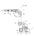
- FIG. 4 is a side view showing the configuration of the robot.
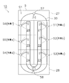
- FIG. 5 is a top view showing the overall configuration of the working system.
- vertical is a concept that includes not only physically strictly vertical but also substantially vertical.
- Substantially perpendicular refers to the case of inclination in the range of 15 ° or less.
- FIG. 1 is a top view showing the overall configuration of a working system 10. As shown in FIG.
- the work system 10 includes six work areas 21 to 26, a movement path 30, a system controller 40, and six robots 51 to 56.
- the work system 10 is generally disposed on the installation surface S.
- Each of the work areas 21 to 26 is an area where work a to work on a work target (hereinafter referred to as "work") is performed.
- the tasks a to f are tasks different from one another. Therefore, the range in which the tasks a to f are performed can be recognized as the task areas 21 to 26, respectively.
- the respective work areas 21 to 26 may be separated from one another or in contact with one another.
- the work areas 21 to 23 are connected to one another in the first direction.
- the work areas 21 to 23 constitute a first line L1 for transporting a work.
- the first line L1 extends in the first direction.
- the first line L1 can be configured, for example, by a belt conveyor for transporting a workpiece.
- the work is transported on the first line L1 in the order of the work area 21 ⁇ the work area 22 ⁇ the work area 23.
- work a is performed by the robot 51.
- work b is performed by two robots 52 and 54.
- the work c is performed by the robot 51.
- one robot is engaged in the work in each of the work area 21 and the work area 23, and two robots are engaged in the work in the work area 22.
- work d to f different from the works a to c in the work areas 21 to 23 are performed.
- the work areas 24 to 26 are apart from the work areas 21 to 23 in a second direction perpendicular to the first direction.
- the work areas 24 to 26 communicate with each other in the first direction.
- the work areas 24 to 26 constitute a second line L2 for transporting a work.
- the second line L2 extends in the first direction.
- the second line L2 is separated from the first line L1 in the second direction.
- a movement path 30 passes between the second line L2 and the first line L1.
- the second line L2 can be configured, for example, by a belt conveyor for transporting a workpiece.
- the work is transported on the second line L2 in the order of the work area 24 ⁇ the work area 25 ⁇ the work area 26.
- work d is performed by the robot 55.
- work e is performed by the robot 56.
- work f is performed by the robot 56.
- one robot is engaged in the work, and the work area 25 and the work area 26 are combined and one robot is engaged in the work.
- the movement path 30 is a flow line of each of the robots 51-56.
- the movement path 30 is adjacent to each of the work areas 21 to 26.
- the movement path 30 is arranged to be connectable to each of the work areas 21 to 26. Therefore, each robot 51 to 56 can access each work area 21 to 26 by moving along the movement path 30.
- the movement path 30 can be configured by, for example, a magnetic marker, a magnetic tape, or an induction cable.
- the movement path 30 may be disposed inside the installation surface S or may be disposed on the installation surface S.
- the movement path 30 has paths 31 to 35.
- the path 31 extends in the first direction.
- the path 31 is adjacent to the work areas 21 to 23 and away from the other work areas.
- the path 32 is connected to one end of the path 31.
- the path 32 extends in the second direction.
- Path 32 is perpendicular to path 31.
- the path 32 is adjacent to the work area 23 and away from the other work areas.
- the path 33 is connected to one end of the path 32.
- the path 33 extends in the first direction.
- the path 33 is parallel to the path 31.
- the path 33 is disposed between the first line L1 and the second line L2.
- the path 33 is located on the opposite side of the path 31 across the work areas 21-23.
- the path 33 is adjacent to all the work areas 21-26.
- the path 34 is connected to one end of the path 33.
- the path 34 extends in the second direction.
- Path 34 is parallel to path 32 and perpendicular to path 33.
- Path 34 is adjacent to work area 24 and is remote from the other work areas.
- the path 35 is connected to one end of the path 34.
- the path 35 extends in the first direction.
- Path 35 is parallel to path 31.
- the path 35 is located on the opposite side of the path 33 across the work areas 24-26.
- the path 35 is located on the opposite side of the path 31 across the work areas 21 to 26.
- Path 35 is adjacent to work areas 24-26 and is remote from the other work areas.
- the system controller 40 can wirelessly communicate with each of the robots 51 to 56.
- the system controller 40 sets the number of robots and the work position in each work area 21 to 26 so that the required time of each work a to f in each work area 21 to 26 is averaged.
- the work system 10 is configured to be able to input a plurality of robots to a work area where complicated work is performed and a work area with a large amount of work, based on disposing one robot in one work area. .
- the system controller 40 notifies the robots 51 to 56 of the work position and the work content before the start of the work.
- the robots 51 to 56 are so-called industrial robots. Specifically, each of the robots 51 to 56 is a self-propelled robot having a plurality of joints. The robots 51 to 56 have the same configuration as one another. The configuration of each of the robots 51 to 56 will be described later.
- Each of the robots 51 to 56 can move to a plurality of positions on the movement path 30, and can perform work on the workpiece from each of the plurality of positions.
- Each of the robots 51 to 56 has a position detection unit 50 for detecting a plurality of positions on the movement path 30.
- the position detection unit 50 may be a coordinate sensor that detects a desired position based on the coordinates set in the movement path, and the emitted light from the light projection unit installed in each of the work areas 21 to 26 may be used. It may be a position sensor that detects a desired position by receiving light.
- FIG. 2 is a top view for explaining the operation of the robot 51 (an example of the first robot) assigned to the work area 21. As shown in FIG.
- the robot 51 performs the work a on the work within the range of the work width Y1 in the first direction of the work area 21.
- the robot 51 is movable to a first position P1 and a second position P2 on the path 31.
- the second position P2 is located on the work area 22 side of the first position P1.
- the first position P1 and the second position P2 are set to positions where the foldable arm 4 of the robot 51 does not interfere with the foldable arms 4 of other robots.
- the working position of the robot 51 is set in each working area 21 to 26 in response to detection of a desired position coordinate by the position detecting unit 50 as described above. It is determined according to the position detection unit 50 receiving the emitted light from the light emitting unit.
- Each of the first position P1 and the second position P2 illustrated in FIG. 2 is an example of the working position of the robot 51, and the actual working position is appropriately set to an appropriate position. Also, only one work position may be set as the work position of the robot 51, or three or more work positions may be set. In the following, the case where the first position P1 and the second position P2 are set as the work position of the robot 51 will be described with reference to FIG.
- the robot 51 After positioning the robot 51 at the first position P1 using the position detection unit 50, the robot 51 performs a part of the work a1 included in the work a on the work. At this time, the robot 51 performs the operation a1 while rotating the folding arm 4 described later in the range of the rotation angle ⁇ 1 about the rotation axis A1. The direction of rotation of the foldable arm 4 may be either right or left. Thereafter, the robot 51 moves toward the work area 22 and positions its own machine at the second position P2 using the position detection unit 50, and then executes the remaining work a2 included in the work a on the work Do. At this time, the robot 51 performs the operation a2 while rotating the folding arm 4 in the range of the rotation angle ⁇ 2 about the rotation axis A1.
- the tasks a1 and a2 included in the task a may be the same task or a series of different tasks.
- the robot 51 can move to the first and second positions P1 and P2 on the path 31, and sequentially performs the operations a1 and a2 on the work from the first and second positions P1 and P2, respectively. It is feasible. Therefore, the rotation angle of the foldable arm 4 of the robot 51 can be made smaller than when both the tasks a1 and a2 are performed in a state where the robot 51 is fixed at one position. Therefore, since the load applied to the robot 51 can be reduced when performing the tasks a1 and a2, the durability of the robot 51 can be improved.
- the timing at which the robot 51 moves from the first position P1 to the second position P2 can be set when the total length of the foldable arm 4 in top view is longer than a predetermined length.
- the robot 51 ends the operation a1 and starts moving to the second position P2.
- the total length of the foldable arm 4 of the robot 51 may be set so as to fall within a predetermined length.
- the timing at which the robot 51 moves from the first position P1 to the second position P2 can be set when the rotation angle of the foldable arm 4 around the rotation axis A1 is larger than a predetermined angle.
- the robot 51 ends the operation a1 and starts moving to the second position P2 .
- the rotation angle of the foldable arm 4 of the robot 51 may be set to fall within a predetermined angle.
- FIG. 3 is a top view for explaining the operation of two robots 52 (an example of a first robot) and robots 54 (an example of a second robot) assigned to the work area 22.
- the two robots 52 and 54 execute the work b on the work on which the work a has been performed within the range of the work width Y2 in the first direction of the work area 22.
- the robot 52 is located at the third position P 3 on the path 31, and the robot 54 is located at the fourth position P 4 on the path 33.
- the fourth position P4 is located on the work area 21 side of the third position P3.
- the working positions of the robots 52 and 54 are determined by the position detecting unit 50 detecting desired position coordinates, or light projected from the working areas 21 to 26. It is determined according to the position detection unit 50 receiving the light emitted from the unit.
- the robot 54 After positioning the robot 54 at the fourth position P4 using the position detection unit 50, the robot 54 executes a part of the work b1 included in the work b on the work. At this time, the robot 54 performs the operation b1 while rotating the folding arm 4 in the range of the rotation angle ⁇ 4 about the rotation axis A1.
- the robot 52 executes the remaining work b2 included in the work b on the work.
- the robot 52 performs the operation b2 while rotating the folding arm 4 in the range of the rotation angle ⁇ 3 about the rotation axis A1.
- the operations b1 and b2 included in the operation b may be the same operation or a series of different operations.
- the robot 53 can execute the operation b2 from the third position P3 different from the fourth position P4 while the robot 54 performs the operation b1 from the fourth position P4. Therefore, for example, the tasks b1 and b2 can be performed more quickly than when the robot 53 performs the tasks b1 and b2 while alternately moving the third position P3 and the fourth position P4. Moreover, since the rotation angles of the foldable arms 4 of the robots 52 and 54 can be reduced similarly to the robot 51 described above, the loads applied to the robots 52 and 54 are reduced when the operations b1 and b2 are performed. Thus, the durability of the robots 52 and 54 can be improved.
- the first direction B1 from the rotation axis A1 of the robot 54 for executing the task b1 to the tip of the arm is from the rotation axis A1 of the robot 52 for performing the task b2 to the tip of the arm It is different from 2 direction B2.
- FIG. 4 is a side view showing the configuration of each of the robots 51-56.
- Each of the robots 51 to 56 is a self-propelled vertical articulated robot.
- Each of the robots 51 to 56 comprises a base frame 2, a swing frame 3 and a foldable arm 4.
- the base frame 2 has a battery 1a and a plurality of wheels 1b.
- the battery 1 a is housed in the base frame 2.
- the plurality of wheels 1 b drive the battery 1 a as a power supply.
- a known AGV self-propelled carriage
- the pivoting frame 3 is disposed on the base frame 2.
- the pivoting frame 3 is supported by the base frame 2.
- the swing frame 3 is rotatable around a rotation axis A1 extending in the vertical direction.
- the folding frame 4 rotates around the rotation axis A1, and the foldable arm 4 also rotates around the rotation axis A1.
- the foldable arm 4 is pivotally attached to the pivoting frame 3.
- the foldable arm 4 is pivotable about a horizontally extending rotation axis A2.
- the foldable arm 4 has a first arm 4a, a second arm 4b, a third arm 4c, and a tool attachment portion 4d.
- the first arm 4a is connected to the swing frame 3 so as to swing around the rotation axis A2.
- the second arm 4b is connected to the first arm 4a so as to swing around a rotational axis A3 extending in the horizontal direction.
- the third arm 4c is connected to the second arm 4b so as to pivot about a pivot axis A4 perpendicular to the rotation axis A3.
- the tool mounting portion 4d is connected to the third arm 4c so as to swing around a rotation axis A5 perpendicular to the pivot axis A4.
- a tool necessary for performing each of the operations a to f is attached to the tip of the tool attachment portion 4d.
- the foldable arm 4 according to the present embodiment has three joints.
- the folding arms 4 are folded and disposed on the swing frame 3 when the robots 51 to 56 move on the movement path 30.
- the postures of the robots 51 to 56 can be made compact to improve traveling stability.
- each of the robots 51 it is preferable that each of the robots 51 to has a posture in which the position of the center of gravity overlaps the movement path 30 in the top view. This can further improve the running stability of each of the robots 51-56.
- the robot 51 is movable to the first position P1 and the second position P2 with reference to FIG. 2, the number of movable positions of the robot 51 is three or more. It may be a substantially infinite number. The same applies to robots other than the robot 51. For example, if the length of each work area is longer than the arm length of each robot, or if the workable length is exceeded by the rotation of the foldable arm 4, three or more movable positions of the robot 51 are required. It becomes.
- the task b is described to be performed in cooperation from the position where the two robots 52, 54 face with reference to FIG. 3, but the positions of the two robots 52, 54 are the same. It is not limited to For example, the robot 54 may execute the work c in the work area 23 by cooperatively executing the work b in the work area 22 from the position where the two robots 52 and 53 are adjacent to each other.
- the work b in the work area 22 is performed by two robots has been described with reference to FIG. 3, but the arrangement of two robots is not limited to the work area 22. .
- the two robots 53 and 54 can execute the work c in the work area 23 in cooperation with each other.
- the robot 53 may be located on the path 31 and the robot 54 may be located on the path 32 or alternatively, the robot 53 may be located on the path 31 and the robot 54 may be on the path 33 It may be located at
- work system 10 was generally arranged in installation side S, it is not restricted to this.
- the work system 10 may be small enough to be disposed on the work bench 5.
- eight robots 51 to 58 movable on the oval movement path 30 execute the tasks a to f in the respective work areas 21 to 26 connected in a C-shape.
- waiting areas 27 and 28 of robots not engaged in the work are prepared.
- the robots 57 and 58 disposed in the standby areas 27 and 28 are put into an open work area when a plurality of robots are inserted into a work area where complicated work is performed and a work area with a large amount of work.
- the robot 57 can be inserted into the work area 21.
- the robot 57 is put into the work area 21 and the work area The robot 58 can be loaded at 25. As a result, it is possible to cope with a work area in which complicated work is performed and a work area with a large amount of work without making a vacancy in each work area.
Landscapes
- Engineering & Computer Science (AREA)
- Robotics (AREA)
- Mechanical Engineering (AREA)
- Manipulator (AREA)
Abstract
【課題】ロボットの耐久性を向上可能な作業システムを提供する。【解決手段】作業システム10は、ロボット51と、ワークに対する作業が実行される作業エリア21と、作業エリア21に隣接する移動経路30とを備える。ロボット51は、移動経路30上の第1及び第2位置P1,P2に移動可能であり、かつ、第1及び第2位置P1,P2それぞれからワークに対して作業を実行可能である。
Description
本発明は、作業システムに関する。
従来、移動経路に沿って複数の作業エリア間を移動可能なロボットを用いて、各作業エリアに配置された作業対象物に対する作業が行われる作業システムが知られている(特許文献1参照)。
特許文献1の作業システムにおいて、ロボットは、カメラ画像に基づいて各作業エリアに対する自機の位置決めを行う。
しかしながら、特許文献1の作業システムにおいて、ロボットは、各作業エリアに対して1つの位置にのみ位置決めされるため、作業中、作業対象物に対してロボットのアームを長く伸ばさなければならない場合がある。この場合、ロボットのベース部分に大きな負荷がかかってしまうため、ロボットの耐久性が低下するという問題がある。
本発明は、上述の状況に鑑みてなされたものであり、ロボットの耐久性を向上可能な作業システムの提供を目的とする。
本発明に係る作業システムの一つの態様は、第1ロボットと、作業対象物に対して作業が実行される作業エリアと、作業エリアに隣接する移動経路とを備える。第1ロボットは、移動経路上の複数の位置に移動可能であり、かつ、複数の位置それぞれから作業対象物に対して作業を実行可能である。
本発明の一つの態様によれば、ロボットの耐久性を向上可能な作業システムを提供することができる。
以下、図面を参照しながら、本発明の一実施形態に係る作業システムについて説明する。ただし、本発明の範囲は、以下の実施の形態に限定されるものではなく、本発明の技術的思想の範囲内で任意に変更可能である。また、以下の図面においては、各構成をわかりやすくするために、各構造における縮尺および数等を、実際の構造における縮尺および数等と異ならせる場合がある。 なお、本明細書において、「平行」とは、物理的に厳密な意味で平行な場合だけでなく、実質的に平行な場合をも含む概念である。実質的に平行とは、15°以下の範囲で傾いている場合をいう。
また、本明細書において、「垂直」とは、物理的に厳密な意味で垂直な場合だけでなく、実質的に垂直な場合をも含む概念である。実質的に垂直とは、15°以下の範囲で傾いている場合をいう。
(作業システム10の全体構成)
図1は、作業システム10の全体構成を示す上面図である。
図1は、作業システム10の全体構成を示す上面図である。
作業システム10は、6箇所の作業エリア21~26と、移動経路30と、システムコントローラ40と、6台のロボット51~56とを備える。作業システム10は、全体的に設置面Sに配置される。
各作業エリア21~26は、作業対象物(以下、「ワーク」という。)に対する作業a~fが実行されるエリアである。作業a~fは、互いに異なる作業である。従って、作業a~fが行われる範囲それぞれを各作業エリア21~26として認識することができる。各作業エリア21~26それぞれは、互いに離れていてもよいし、互いに接していてもよい。
作業エリア21~23は、第1方向において互いに連なる。作業エリア21~23は、ワークを搬送するための第1ラインL1を構成する。第1ラインL1は、第1方向に延びる。第1ラインL1は、例えば、ワークを搬送するためのベルトコンベアによって構成することができる。
ワークは、作業エリア21→作業エリア22→作業エリア23の順に第1ラインL1上を搬送される。作業エリア21では、ロボット51によって作業aが行われる。作業エリア22では、2台のロボット52,54によって作業bが行われる。作業エリア23では、ロボット51によって作業cが行われる。このように、図1に示す例では、作業エリア21及び作業エリア23それぞれにおいて1台のロボットが作業に従事し、作業エリア22では2台のロボットが作業に従事している。
作業エリア24~26では、作業エリア21~23における作業a~cとは異なる作業d~fが行われる。作業エリア24~26は、第1方向に垂直な第2方向において、作業エリア21~23から離れている。
作業エリア24~26は、第1方向において互いに連なる。作業エリア24~26は、ワークを搬送するための第2ラインL2を構成する。第2ラインL2は、第1方向に延びる。第2ラインL2は、第2方向において第1ラインL1から離れている。第2ラインL2と第1ラインL1との間には、移動経路30が通っている。第2ラインL2は、例えば、ワークを搬送するためのベルトコンベアによって構成することができる。
ワークは、作業エリア24→作業エリア25→作業エリア26の順に第2ラインL2上を搬送される。作業エリア24では、ロボット55によって作業dが行われる。作業エリア25では、ロボット56によって作業eが行われる。作業エリア26では、ロボット56によって作業fが行われる。このように、図1に示す例では、作業エリア24では1台のロボットが作業に従事し、作業エリア25及び作業エリア26を合わせて1台のロボットが作業に従事している。
移動経路30は、各ロボット51~56の動線である。移動経路30は、各作業エリア21~26に隣接する。移動経路30は、各作業エリア21~26に接続できるように配置されている。従って、各ロボット51~56は、移動経路30に沿って移動することによって、各作業エリア21~26にアクセスすることができる。移動経路30は、例えば磁気マーカ、磁気テープ、或いは、誘導ケーブルなどによって構成することができる。移動経路30は、設置面Sの内部に配置されていてもよいし、設置面S上に配置されていてもよい。
移動経路30は、経路31~35を有する。
経路31は、第1方向に延びる。経路31は、作業エリア21~23に隣接し、他の作業エリアからは離れている。
経路32は、経路31の一端に連なる。経路32は、第2方向に延びる。経路32は、経路31に対して垂直である。経路32は、作業エリア23に隣接し、他の作業エリアからは離れている。
経路33は、経路32の一端に連なる。経路33は、第1方向に延びる。経路33は、経路31に平行である。経路33は、第1ラインL1と第2ラインL2との間に配置される。経路33は、作業エリア21~23を挟んで経路31の反対側に位置する。経路33は、すべての作業エリア21~26に隣接する。
経路34は、経路33の一端に連なる。経路34は、第2方向に延びる。経路34は、経路32に平行であり、経路33に対して垂直である。経路34は、作業エリア24に隣接し、他の作業エリアからは離れている。
経路35は、経路34の一端に連なる。経路35は、第1方向に延びる。経路35は、経路31に平行である。経路35は、作業エリア24~26を挟んで経路33の反対側に位置する。経路35は、作業エリア21~26を挟んで経路31の反対側に位置する。経路35は、作業エリア24~26に隣接し、他の作業エリアから離れている。
システムコントローラ40は、各ロボット51~56と無線通信可能である。システムコントローラ40は、各作業エリア21~26における各作業a~fの所要時間が平均化されるように、各作業エリア21~26におけるロボットの台数及び作業位置を設定する。
図1に示す例では、作業エリア25,26における作業e,fの負荷が小さい一方で、作業エリア22における作業bの負荷が大きい場合が想定されている。そのため、作業エリア25,26には1台のロボット56のみが割り当てられ、作業エリア22には2台のロボット52,54が割り当てられている。作業システム10は、1つの作業エリアに1つのロボットを配置することを基本としつつ、煩雑な作業が行われる作業エリアや作業量の多い作業エリアに複数のロボットを投入できるように構成されている。システムコントローラ40は、作業開始前に、各ロボット51~56に対して作業位置と作業内容とを通知する。
各ロボット51~56は、いわゆる産業用ロボットである。具体的には、各ロボット51~56は、複数の関節部を有する自走式ロボットである。各ロボット51~56は、互いに同様の構成を有する。各ロボット51~56の構成については後述する。
各ロボット51~56は、移動経路30上の複数の位置に移動可能であり、かつ、複数の位置それぞれからワークに対して作業を実行可能である。各ロボット51~56は、移動経路30上の複数の位置を検出するための位置検出部50を有する。位置検出部50は、移動経路に設定された座標に基づいて、所望の位置を検出する座標センサであってもよいし、各作業エリア21~26に設置された投光部からの出射光を受光することによって所望の位置を検出するポジションセンサであってもよい。
ここで、図2は、作業エリア21に割り当てられたロボット51(第1ロボットの一例)の動作を説明するための上面図である。
ロボット51は、作業エリア21の第1方向における作業幅Y1の範囲内において、ワークに対して作業aを実行する。ロボット51は、経路31上の第1位置P1と第2位置P2とに移動可能である。第2位置P2は、第1位置P1の作業エリア22側に位置する。第1位置P1及び第2位置P2それぞれは、ロボット51の折り畳み式アーム4が他のロボットの折り畳み式アーム4と干渉しない位置に設定される。図2には図示されていないが、ロボット51の作業位置は、上述したとおり、位置検出部50が所望の位置座標を検出したことに応じて、或いは、各作業エリア21~26に設置された投光部からの出射光を位置検出部50が受光したことに応じて決められる。
なお、図2に図示された第1位置P1及び第2位置P2それぞれは、ロボット51の作業位置の一例であり、実際の作業位置は適宜適切な位置に設定される。また、ロボット51の作業位置として、1つの作業位置のみが設定されてもよいし、3つ以上の作業位置が設定されてもよい。以下においては、図2を参照しながら、ロボット51の作業位置として第1位置P1及び第2位置P2が設定されている場合について説明する。
ロボット51は、位置検出部50を用いて第1位置P1に自機を位置決めした後、作業aに含まれる一部の作業a1をワークに対して実行する。この際、ロボット51は、後述する折り畳み式アーム4を、回転軸A1を中心として回転角θ1の範囲で回転させながら作業a1を実行する。折り畳み式アーム4の回転方向は、右周り及び左周りのいずれであってもよい。その後、ロボット51は、作業エリア22側に向かって移動し、位置検出部50を用いて第2位置P2に自機を位置決めした後、作業aに含まれる残りの作業a2をワークに対して実行する。この際、ロボット51は、折り畳み式アーム4を、回転軸A1を中心として回転角θ2の範囲で回転させながら作業a2を実行する。なお、作業aに含まれる作業a1,a2は、同じ作業であってもよいし、一連の異なる作業であってもよい。
このように、ロボット51は、経路31上の第1及び第2位置P1,P2に移動可能であり、かつ、第1及び第2位置P1,P2それぞれからワークに対して作業a1,a2を順次実行可能である。そのため、ロボット51が1つの位置に固定された状態で作業a1,a2の両方を実行する場合に比べて、ロボット51の折り畳み式アーム4の回転角を小さくすることができる。従って、作業a1,a2を実行する際にロボット51にかかる負荷を小さくすることができるため、ロボット51の耐久性を向上させることができる。
なお、ロボット51が第1位置P1から第2位置P2に移動するタイミングは、上面視における折り畳み式アーム4の全長が所定長より長くなったときに設定することができる。この場合、ロボット51は、第1位置P1における作業a1の作業中、折り畳み式アーム4の全長が所定長より長くなったときに、作業a1を終了させて、第2位置P2に移動開始する。第2位置P2における作業a2の作業中、ロボット51の折り畳み式アーム4の全長は、所定長以内に収まるように設定されていればよい。
或いは、ロボット51が第1位置P1から第2位置P2に移動するタイミングは、回転軸A1周りの折り畳み式アーム4の回転角が所定角より大きくなったときに設定することができる。この場合、ロボット51は、第1位置P1における作業a1の作業中、折り畳み式アーム4の回転角が所定角より大きくなったときに、作業a1を終了させて、第2位置P2に移動開始する。第2位置P2における作業a2の作業中、ロボット51の折り畳み式アーム4の回転角は所定角以内に収まるように設定されていればよい。
以上、図2を参照しながら説明したロボット51の動作は、ロボット53,55,66それぞれにも適用可能である。
一方、図3は、作業エリア22に割り当てられた2台のロボット52(第1ロボットの一例)及びロボット54(第2ロボットの一例)の動作を説明するための上面図である。
2台のロボット52,54は、作業エリア22の第1方向における作業幅Y2の範囲内において、作業aが実行済みのワークに対して作業bを実行する。ロボット52は、経路31上の第3位置P3に位置し、ロボット54は、経路33上の第4位置P4に位置する。第4位置P4は、第3位置P3の作業エリア21側に位置する。図3には図示されていないが、ロボット52,54の作業位置は、位置検出部50が所望の位置座標を検出したことに応じて、或いは、各作業エリア21~26に設置された投光部からの出射光を位置検出部50が受光したことに応じて決められる。
ロボット54は、位置検出部50を用いて第4位置P4に自機を位置決めした後、作業bに含まれる一部の作業b1をワークに対して実行する。この際、ロボット54は、折り畳み式アーム4を、回転軸A1を中心として回転角θ4の範囲で回転させながら作業b1を実行する。
一方、ロボット52は、位置検出部50を用いて第3位置P3に自機を位置決めした後、作業bに含まれる残りの作業b2をワークに対して実行する。この際、ロボット52は、折り畳み式ア
ーム4を、回転軸A1を中心として回転角θ3の範囲で回転させながら作業b2を実行する。なお、作業bに含まれる作業b1,b2は、同じ作業であってもよいし、一連の異なる作業であってもよい。
ーム4を、回転軸A1を中心として回転角θ3の範囲で回転させながら作業b2を実行する。なお、作業bに含まれる作業b1,b2は、同じ作業であってもよいし、一連の異なる作業であってもよい。
このように、ロボット54が第4位置P4から作業b1を実行しながら、ロボット53は第4位置P4とは異なる第3位置P3から作業b2を実行することができる。従って、例えばロボット53が第3位置P3と第4位置P4とを交互に移動しながら作業b1,b2を実行する場合に比べて、迅速に作業b1,b2を実行することができる。また、上述したロボット51と同様、ロボット52,54それぞれの折り畳み式アーム4の回転角を小さくすることができるため、作業b1,b2を実行する際にロボット52,54それぞれにかかる負荷を小さくして、ロボット52,54の耐久性を向上させることもできる。
なお、図3に示すように、作業b1を実行するロボット54の回転軸A1からアームの先端に向かう第1向きB1は、作業b2を実行するロボット52の回転軸A1からアームの先端に向かう第2向きB2とは異なる。
(各ロボット51~56の構成)
図4は、各ロボット51~56の構成を示す側面図である。
図4は、各ロボット51~56の構成を示す側面図である。
各ロボット51~56は、自走式の垂直多関節ロボットである。各ロボット51~56は、ベースフレーム2と、旋回フレーム3と、折り畳み式アーム4とを備える。
ベースフレーム2は、バッテリ1aと複数の車輪1bとを有する。バッテリ1aは、ベースフレーム2内に収容される。複数の車輪1bは、バッテリ1aを電源として駆動する。ベースフレーム2としては、周知のAGV(自走式台車)を用いることができる。
旋回フレーム3は、ベースフレーム2上に配置される。旋回フレーム3は、ベースフレーム2によって支持される。旋回フレーム3は、鉛直方向に延びる回転軸A1を中心として回転可能である。旋回フレーム3が回転軸A1を中心として回転することによって、折り畳み式アーム4も回転軸A1を中心として回転する。
折り畳み式アーム4は、旋回フレーム3に揺動可能に取り付けられる。折り畳み式アーム4は、水平方向に延びる回転軸A2を中心として揺動可能である。
折り畳み式アーム4は、第1アーム4aと、第2アーム4bと、第3アーム4cと、ツール取付け部4dとを有する。第1アーム4aは、回転軸A2を中心として揺動するように、旋回フレーム3に連結される。第2アーム4bは、水平方向に延びる回転軸A3を中心として揺動するように、第1アーム4aに連結される。第3アーム4cは、回転軸A3に対して垂直な旋回軸A4を中心として旋回するように、第2アーム4bに連結される。ツール取付け部4dは、旋回軸A4に対して垂直な回転軸A5を中心として揺動するように、第3アーム4cに連結される。ツール取付け部4dの先端には、作業a~fそれぞれの実行に必要なツールが取り付けられる。このように、本実施形態に係る折り畳み式アーム4は、3つの関節を有している。
折り畳み式アーム4は、各ロボット51~56が移動経路30上を移動する場合、折り畳まれて、旋回フレーム3上に配置される。折り畳み式アーム4が折り畳まれることによって、各ロボット51~56の姿勢がコンパクトになって走行安定性を向上させることができる。
また、移動時、各ロボット51~56は、上面視において重心位置が移動経路30と重なるような姿勢を取ることが好ましい。これによって、各ロボット51~56の走行安定性をさらに向上させることができる。
(他の実施形態)
上記実施形態では、図2を参照しながら、ロボット51が第1位置P1と第2位置P2とに移動可能であることを説明したが、ロボット51が移動可能な位置の数は3以上であってもよく、実質的に無限数であってもよい。このことはロボット51以外のロボットにおいても同様である。例えば、各作業エリアの長さが、各ロボットのアーム長より長い場合や、折り畳み式アーム4の回転によって作業可能な長さを超えた場合は、ロボット51の移動可能な位置は3つ以上必要となる。
上記実施形態では、図2を参照しながら、ロボット51が第1位置P1と第2位置P2とに移動可能であることを説明したが、ロボット51が移動可能な位置の数は3以上であってもよく、実質的に無限数であってもよい。このことはロボット51以外のロボットにおいても同様である。例えば、各作業エリアの長さが、各ロボットのアーム長より長い場合や、折り畳み式アーム4の回転によって作業可能な長さを超えた場合は、ロボット51の移動可能な位置は3つ以上必要となる。
上記実施形態では、図3を参照しながら、2台のロボット52,54が対向する位置から作業bを協働して実行することを説明したが、2台のロボット52,54の位置はこれに限られるものではない。例えば、2台のロボット52,53が隣り合う位置から作業エリア22における作業bを協働して実行し、ロボット54が作業エリア23における作業cを実行してもよい。
上記実施形態では、図3を参照しながら、作業エリア22における作業bを2台のロボットで実行する場合について説明したが、2台のロボットを配置できるのは作業エリア22に限られるものではない。例えば、作業エリア23における作業cの負荷が大きい場合には、2台のロボット53,54が作業エリア23における作業cを協働して実行することができる。この場合、ロボット53は経路31上に位置し、かつ、ロボット54は経路32上に位置していてもよいし、或いは、ロボット53は経路31上に位置し、かつ、ロボット54は経路33上に位置していてもよい。
上記実施形態では、作業システム10は、全体的に設置面Sに配置されることとしたが、これに限られるものではない。例えば、図5に示すように、作業システム10は、作業台5上に配置可能な程度の小サイズであってもよい。図5に示す例では、オーバル状の移動経路30を移動自在な8台のロボット51~58が、C字状に連なる各作業エリア21~26において各作業a~fを実行する。C字状の各作業エリア21~26の両側には、作業に従事しないロボットの待機エリア27,28が準備されている。待機エリア27,28に配置されたロボット57、58は、煩雑な作業が行われる作業エリアや作業量の多い作業エリアに複数のロボットを投入した場合に、空いた作業エリアに投入される。例えば、作業スポット22にロボット51及びロボット52の2台を投入する場合、作業エリア21にロボット57を投入することができる。また、作業エリア22にロボット51及びロボット52の2台を投入し、かつ、作業エリア25にロボット54及びロボット55の2台を投入する場合、作業エリア21にロボット57投入し、かつ、作業エリア25にロボット58を投入することができる。これによって、各作業エリアに空きを作ることなく、煩雑な作業が行われる作業エリアや作業量の多い作業エリアに対応することができる。
2 ベースフレーム
3 旋回フレーム
4 折り畳み式アーム
10 作業システム
21~26 作業エリア
30 移動経路
31~35 経路
40 システムコントローラ
51~58 ロボット
L1 第1ライン
L2 第2ライン
A1 回転軸
a~f 作業
3 旋回フレーム
4 折り畳み式アーム
10 作業システム
21~26 作業エリア
30 移動経路
31~35 経路
40 システムコントローラ
51~58 ロボット
L1 第1ライン
L2 第2ライン
A1 回転軸
a~f 作業
Claims (14)
- 第1ロボットと、
作業対象物に対する作業が実行される作業エリアと、
前記作業エリアに隣接する移動経路と、
を備え、
前記第1ロボットは、前記移動経路上の複数の位置に移動可能であり、かつ、前記複数の位置それぞれから前記作業対象物に対して作業を実行可能である、
作業システム。 - 前記移動経路上の複数の位置に移動可能であり、かつ、前記複数の位置それぞれから前記作業対象物に対して作業を実行可能な第2ロボットを更に備え、
前記第2ロボットは、前記第1ロボットとは異なる位置から前記作業対象物に対して作業を実行可能である、
請求項1に記載の作業システム。 - 前記第1ロボット及び前記第2ロボットのそれぞれは、
前記移動経路上に配置されるベースフレームと、
前記ベースフレーム上に配置され、鉛直方向に延びる回転軸を中心として回転可能な旋回フレームと、
前記旋回フレームに揺動可能に取り付けられるアームと、
を有し、
前記第1ロボットにおいて前記回転軸から前記アームの先端に向かう第1向きは、前記第2ロボットにおいて前記回転軸から前記アームの先端に向かう第2向きと異なる、
請求項2に記載の作業システム。 - 前記移動経路は、前記第1ロボットが位置する第1経路と、前記第2ロボットが位置する第2経路とを含み、
前記第1経路の延びる方向は、前記第2経路の延びる方向と交差する、
請求項2に記載の作業システム。 - 前記移動経路は、前記第1ロボットが位置する第1経路と、前記第2ロボットが位置する第2経路とを含み、
前記第1経路は、前記作業エリアを挟んで前記第2経路の反対側に位置する、
請求項2に記載の作業システム。 - 前記第1ロボットは、前記複数の位置を検出するための位置検出部を有する、
請求項1乃至5のいずれかに記載の作業システム。 - 前記位置検出部は、前記移動経路に設定された座標に基づいて、所望の位置を検出する、
請求項6に記載の作業システム。 - 前記位置検出部は、前記作業エリアに設置された投光部からの出射光を受光することによって、前記所望の位置を検出する、
請求項6に記載の作業システム。 - 前記第1ロボットは、前記移動経路上に配置されるベースフレームと、前記ベースフレーム上に配置され、鉛直方向に延びる回転軸を中心として回転可能な旋回フレームと、前記旋回フレームに揺動可能に取り付けられるアームとを有し、
前記第1ロボットは、作業中、上面視における前記アームの全長が所定長より長くなったとき、前記複数の位置のうち、前記アームの全長が前記所定長以内に収まる位置に移動する、
請求項1に記載の作業システム。 - 前記第1ロボットは、前記移動経路上に配置されるベースフレームと、前記ベースフレーム上に配置され、鉛直方向に延びる回転軸を中心として回転可能な旋回フレームと、前記旋回フレームに揺動可能に取り付けられるアームとを有し、
前記第1ロボットは、作業中、前記回転軸周りの前記アームの回転角が所定角より大きくなったとき、前記複数の位置のうち、前記アームの回転角が前記所定角以内に収まる位置に移動する、
請求項1に記載の作業システム。 - 前記第1ロボットが前記移動経路上を移動する場合、上面視において、前記第1ロボットの重心は、前記移動経路と重なる、
請求項1に記載の作業システム。 - 前記第1ロボットは、
前記移動経路上に配置されるベースフレームと、
前記ベースフレーム上に配置され、鉛直方向に延びる回転軸を中心として回転可能な旋回フレームと、
前記旋回フレームに揺動可能に取り付けられるアームと、
を有し、
前記第1ロボットが前記移動経路上を移動する場合、前記アームは、前記旋回フレーム上に配置される、
請求項11に記載の作業システム。 - 前記アームは、少なくとも1つの関節を有する折り畳み式アームであり、
前記前記第1ロボットが前記移動経路上を移動する場合、前記アームは折り畳まれる、
請求項12に記載の作業システム。 - 前記第1ロボット、前記作業エリア及び前記移動経路が配置される作業台を更に備え、
前記作業エリアは、複数の作業スポットを含み、
前記移動経路は、前記複数の作業スポットそれぞれに隣接する、
請求項1乃至13のいずれかに記載の作業システム。
Applications Claiming Priority (2)
| Application Number | Priority Date | Filing Date | Title |
|---|---|---|---|
| JP2017163875 | 2017-08-29 | ||
| JP2017-163875 | 2017-08-29 |
Publications (1)
| Publication Number | Publication Date |
|---|---|
| WO2019044136A1 true WO2019044136A1 (ja) | 2019-03-07 |
Family
ID=65525144
Family Applications (1)
| Application Number | Title | Priority Date | Filing Date |
|---|---|---|---|
| PCT/JP2018/023732 Ceased WO2019044136A1 (ja) | 2017-08-29 | 2018-06-22 | 作業システム |
Country Status (1)
| Country | Link |
|---|---|
| WO (1) | WO2019044136A1 (ja) |
Citations (6)
| Publication number | Priority date | Publication date | Assignee | Title |
|---|---|---|---|---|
| JPS6248475A (ja) * | 1985-08-29 | 1987-03-03 | フアナツク株式会社 | 自走形移動ロボツト |
| JPS62203789A (ja) * | 1986-03-04 | 1987-09-08 | 日産自動車株式会社 | 追従制御装置 |
| JPH05293775A (ja) * | 1992-04-16 | 1993-11-09 | Komatsu Ltd | ワークハンドリング機械の制御方法 |
| JP2013193155A (ja) * | 2012-03-19 | 2013-09-30 | Yaskawa Electric Corp | ロボットシステム及びロボットハンドの爪保持機構 |
| WO2016103303A1 (ja) * | 2014-12-26 | 2016-06-30 | 川崎重工業株式会社 | 自走式関節ロボット |
| WO2016113854A1 (ja) * | 2015-01-14 | 2016-07-21 | 三菱電機株式会社 | 位置決め装置 |
-
2018
- 2018-06-22 WO PCT/JP2018/023732 patent/WO2019044136A1/ja not_active Ceased
Patent Citations (6)
| Publication number | Priority date | Publication date | Assignee | Title |
|---|---|---|---|---|
| JPS6248475A (ja) * | 1985-08-29 | 1987-03-03 | フアナツク株式会社 | 自走形移動ロボツト |
| JPS62203789A (ja) * | 1986-03-04 | 1987-09-08 | 日産自動車株式会社 | 追従制御装置 |
| JPH05293775A (ja) * | 1992-04-16 | 1993-11-09 | Komatsu Ltd | ワークハンドリング機械の制御方法 |
| JP2013193155A (ja) * | 2012-03-19 | 2013-09-30 | Yaskawa Electric Corp | ロボットシステム及びロボットハンドの爪保持機構 |
| WO2016103303A1 (ja) * | 2014-12-26 | 2016-06-30 | 川崎重工業株式会社 | 自走式関節ロボット |
| WO2016113854A1 (ja) * | 2015-01-14 | 2016-07-21 | 三菱電機株式会社 | 位置決め装置 |
Similar Documents
| Publication | Publication Date | Title |
|---|---|---|
| JP6979012B2 (ja) | 基板搬送装置及び基板搬送ロボットの教示方法 | |
| US9248875B2 (en) | Driving flipper with robotic arm | |
| JP2019166657A5 (ja) | ||
| US20140140801A1 (en) | Substrate transfer robot and substrate transfer method | |
| US9120223B2 (en) | Method of controlling seven-axis articulated robot, control program, and robot control device | |
| US10195750B2 (en) | Robot and robot system | |
| KR101421351B1 (ko) | 병렬로봇 | |
| JP6842983B2 (ja) | ロボットシステム及びそれを備える作業ライン | |
| CN111055264B (zh) | 机器人和第一臂构件 | |
| US20160031095A1 (en) | Robot | |
| US10569428B2 (en) | Robot | |
| JP5803887B2 (ja) | ロボット | |
| US20160031094A1 (en) | Robot | |
| CN106002987A (zh) | 机器人 | |
| JP6712114B2 (ja) | リンク式多関節ロボットおよびロボットシステム | |
| WO2019220827A1 (ja) | 垂直多関節溶接ロボット | |
| JP4982413B2 (ja) | 脚車輪型移動ロボット | |
| CN107428012A (zh) | 机械手、机械手的控制方法、工件的安装方法以及工件的搬运方法 | |
| JP2007118176A (ja) | 移動型マニピュレータ | |
| JP2022091409A (ja) | ロボットシステム | |
| WO2019044136A1 (ja) | 作業システム | |
| JP6386704B2 (ja) | ワーク搬送装置 | |
| JP7278930B2 (ja) | 保持装置、ロボット、及びロボットシステム | |
| KR101331368B1 (ko) | 사행 보상 기능을 구비하는 기판 반송용 로봇 및 그의 사행 보상 방법 | |
| JP7259487B2 (ja) | 制御方法およびロボットシステム |
Legal Events
| Date | Code | Title | Description |
|---|---|---|---|
| 121 | Ep: the epo has been informed by wipo that ep was designated in this application |
Ref document number: 18851622 Country of ref document: EP Kind code of ref document: A1 |
|
| NENP | Non-entry into the national phase |
Ref country code: DE |
|
| 122 | Ep: pct application non-entry in european phase |
Ref document number: 18851622 Country of ref document: EP Kind code of ref document: A1 |
|
| NENP | Non-entry into the national phase |
Ref country code: JP |