WO2019039501A1 - ブレーキパッド摩耗検出器 - Google Patents
ブレーキパッド摩耗検出器 Download PDFInfo
- Publication number
- WO2019039501A1 WO2019039501A1 PCT/JP2018/030947 JP2018030947W WO2019039501A1 WO 2019039501 A1 WO2019039501 A1 WO 2019039501A1 JP 2018030947 W JP2018030947 W JP 2018030947W WO 2019039501 A1 WO2019039501 A1 WO 2019039501A1
- Authority
- WO
- WIPO (PCT)
- Prior art keywords
- base
- rotor
- lining
- brake pad
- wear detector
- Prior art date
- Legal status (The legal status is an assumption and is not a legal conclusion. Google has not performed a legal analysis and makes no representation as to the accuracy of the status listed.)
- Ceased
Links
Images


Classifications
-
- F—MECHANICAL ENGINEERING; LIGHTING; HEATING; WEAPONS; BLASTING
- F16—ENGINEERING ELEMENTS AND UNITS; GENERAL MEASURES FOR PRODUCING AND MAINTAINING EFFECTIVE FUNCTIONING OF MACHINES OR INSTALLATIONS; THERMAL INSULATION IN GENERAL
- F16D—COUPLINGS FOR TRANSMITTING ROTATION; CLUTCHES; BRAKES
- F16D66/00—Arrangements for monitoring working conditions, e.g. wear, temperature
- F16D66/02—Apparatus for indicating wear
Definitions
- the present invention relates to a brake pad wear detector.
- a disk brake disclosed in Patent Document 1 below is known.
- This conventional disc brake is a brake that warns the user that the brake pad lining that is pressed against the side of the disc rotor that rotates with the wheel and generates a braking force is worn and the brake pad (lining) usage limit has been reached.
- It has a pad wear detector.
- the brake pad wear detector has a sensor piece formed by bending a metal plate, and the sensor piece is fixed to a back plate that supports the lining.
- the brake pad wear detector generates a warning sound (audible sound) by vibrating in contact with the disc rotor when the lining wears to the use limit.
- the brake pad wear detector provided in the above-mentioned conventional disk brake forms a vibrating portion by projecting the main body of the sensor piece on the surface (cylinder pressing surface) opposite to the disk rotor of the back plate.
- the tip of the piece is adapted to face the disc rotor.
- the present invention has been made to solve the above-mentioned problems, and it is an object of the present invention to provide a brake pad wear detector that can generate a stable warning sound without interference from other parts.
- the invention of the brake pad wear detector according to claim 1 comprises a disk rotor connected to a rotating member of a vehicle and integrally rotating with the rotating member, and a part of an outer peripheral portion of the disk rotor.
- a caliper is provided so as to straddle and fixed to a non-rotating member of the vehicle, and a lining formed opposite to the side surface of the disk rotor and a back plate fixed to the lining, and has a pair of brake pads assembled to the caliper.
- a disc brake device a mounting portion attached to the back plate of the brake pad, a warning portion extended from the mounting portion, and in contact with the disc rotor when the lining is worn to warn the lining of wear
- the brake pad wear detector wherein the warning portion has one end connected to the mounting portion and curves toward the side of the disc rotor A proximal end is connected to the curved portion and the other end of the curved portion, and a base which is opposed to the side surface of the disc rotor and extends along the radial direction of the disc rotor and is connected to a distal end opposite to the proximal end of the base; Inside the outer periphery of the disc rotor, it protrudes toward the disc rotor toward the disc rotor, and the projecting part which can contact the sliding contact part of the disc rotor in sliding contact with the lining, and the connecting part between the base and the projecting part And at least one of the formed first notches.
- the brake pad wear detector avoids interference with other members (for example, a cylinder, a piston, etc.) provided on the caliper by providing the curved portion, the base and the projecting portion on the side of the disk rotor. It is possible to improve the degree of freedom in designing the curved portion, the base portion, the projecting portion and the like. Therefore, the warning unit K can stably generate a warning sound (audible sound) having an appropriate tone (audio frequency) and a sufficient volume. Further, by providing the base with the first notch, it is possible to alleviate the stress concentration caused by the base bending when the lining is worn and the projection contacts the sliding contact portion of the disc rotor. As a result, the base and the projection can have sufficient mechanical strength, and the projection can contact the sliding portion properly, and as a result, the warning unit can emit a warning sound (audible sound). Can be generated stably.
- other members for example, a cylinder, a piston, etc.
- the disk brake device 10 is, for example, a piston opposed disk brake device.
- the disk brake device 10 it is also possible to use a floating disk brake device having a mounting.
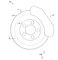
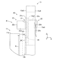
- the disk brake device 10 includes a disk-shaped disk rotor 11 and a caliper 12 straddling a part of the outer peripheral portion of the disk rotor 11.
- the disk rotor 11 is formed of a metal material (for example, cast iron or the like).
- the disk rotor 11 is composed of a disk-shaped rotor main body 11 a and a cylindrical hat portion 11 b fastened to an axle (not shown) as a rotating member of the vehicle by bolts and nuts.
- the disk rotor 11, that is, the rotor main body 11a and the hat portion 11b rotate integrally with the rotating member of the vehicle.
- the rotor main body 11a has a sliding contact portion R in sliding contact with a lining 13b of a pair of brake pads 13 described later on a side surface inside the outer peripheral portion.
- the axial direction X of the disk-shaped disk rotor 11 is referred to as the first direction X
- Y is referred to as a second direction Y
- a direction Z orthogonal to the first direction X and the second direction Y, that is, the radial direction Z of the disk rotor 11 is referred to as a third direction Z. That is, the first direction X, the second direction Y, and the third direction Z are orthogonal to each other.
- the caliper 12 is formed of a metal material (for example, aluminum).
- the caliper 12 is fixed to a non-rotating member (for example, a vehicle body (not shown)) of the vehicle.
- the caliper 12 has an inner portion 12a, an outer portion 12b, a bridge portion 12c and a window portion 12d.
- the inner portion 12a and the outer portion 12b are respectively disposed on both sides in the first direction X, and are configured to receive pistons (not shown) in cylinders (not shown).
- the bridge portion 12c connects the inner portion 12a and the outer portion 12b, and receives a braking torque transmitted from a pair of brake pads 13 described later at the time of braking.
- the window portion 12d is formed by the inner portion 12a, the outer portion 12b, and the bridge portion 12c. A pair of brake pads 13 are accommodated and incorporated in the window 12 d.
- the pair of brake pads 13 incorporated inside the caliper 12 is pressed toward the side surface of the disk rotor 11, more specifically, toward the sliding contact portion R by the operation of the piston advancing and retracting along the first direction X.
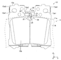
- Each of the pair of brake pads 13 has a back plate 13 a and a lining 13 b which is a friction material, as shown in FIGS. 2 and 3.
- the back plate 13a is formed in a plate shape, and has an insertion hole 13a1 for inserting a pair of pad pins 14 (see FIG. 2) and a concave mounting portion 13a2 to which a wear detector 20 described later is mounted. doing.
- the lining 13b is fixed by adhesion to the surface 13a3 side, and the back surface 13a4 side is pressed by the piston.
- the lining 13 b moves in the first direction X together with the back plate 13 a and is in sliding contact with the sliding contact portion R of the disk rotor 11.
- the lining 13 b is formed to have a predetermined thickness from, for example, an organic friction material using aramid transition, inorganic fibers, steel fibers, and the like.
- the predetermined thickness of the lining 13b is set based on the surface 13a3 of the back plate 13a.
- the wear detector 20 is mounted to the mounting portion 13a2 of the back plate 13a, as shown in FIGS.
- the wear detector 20 wears and becomes thin as the lining 13 b slides on the sliding contact portion R of the disc rotor 11 and contacts the rotating disc rotor 11 when the use limit of the lining 13 b is reached.
- the wear detector 20 generates a warning sound (audible sound) having an audio frequency set in advance in order to make the user recognize the wear of the lining 13b.
- a warning sound there are a sliding sound, a contact sound, a vibration sound and the like.
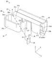
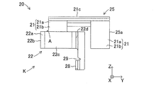
- the wear detector 20 is formed by bending a metal material having a spring property, for example, a metal plate such as stainless steel, and as shown in FIGS. 4 to 7, the attachment detector 21 and the warning unit K are configured. And a base portion 23 and a projecting portion 24.
- the mounting portion 21 is opposite to the first surface 21a in contact with the surface 13a3 of the back plate 13a and the side surface (sliding portion R) of the disk rotor 11 opposite to the first surface 21a in the first direction X And a second surface 21b.
- the second surface 21 b is provided to be flat (flat) in a direction along the second direction Y and the third direction Z.
- the wear detector 20 is mounted on the mounting portion 13a2 of the back plate 13a such that the first surface 21a is in close contact with the surface 13a3 (see FIG. 7).
- the lining 13 b and the mounting portion 21 are fixed to the surface of the same height in the first direction X. Therefore, as shown in FIG. 7, the installation height in the first direction X of the wear detector 20 for detecting the thickness (the remaining thickness after wear) of the lining 13b is accurately set.
- the mounting portion 21 is fixed to the mounting portion 13a2 in a biased state by an elastic clip 25 (sandwich) sandwiching the front surface 13a3 and the back surface 13a4 of the back plate 13a.
- the elastic clip 25 has a first urging portion 25a abutting on the surface 13a3 and a second urging portion 25b abutting on the back surface 13a4.
- the elastic clip 25 connects the first biasing portion 25a and the second biasing portion 25b, and has a connecting portion 25c formed so as to straddle the surface 13a3 and the back surface 13a4.
- the first biasing portion 25 a is divided into two, and one of the divided portions doubles as the mounting portion 21. That is, a part of the first biasing portion 25 a forms the mounting portion 21.
- the second biasing portion 25b has an engaging claw 25d whose central portion is folded back from the back surface 13a4 to the surface 13a3 in the first direction X.
- the engaging claws 25 d are adapted to position the elastic clip 25 by engaging with the recessed portions 13 a 5 (engaged portions) formed in the back plate 13 a. That is, the engagement claws 25d determine the position of the wear detector 20 with respect to the back plate 13a.
- the second urging portion 25b is inclined obliquely so as to approach the first urging portion 25a in the first direction X in a free state where the second urging portion 25b is not attached to the attachment portion 13a2 of the back plate 13a. .
- the second urging portion 25b generates a spring force by being spread from the back surface 13a4 in the first direction X in a direction opposite to the surface 13a3 when the second urging portion 25b is attached to the attachment portion 13a2.
- the back plate 13a is held between the first biasing portion 25a and the second biasing portion 25b in a biasing state, and the elastic clip 25, that is, the wear detector 20 is fixed to the mounting portion 13a2 of the back plate 13a.
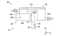
- the mounting portion 21 has a bent portion 21c formed at the connection position of the first urging portion 25a and the connection portion 25c. As shown in FIGS. 6 and 7, the bending portion 21c is bent along the third direction Z (that is, the radial direction of the disk rotor 11) so as to be separated from the mounting portion 13a2. Thus, the mounting portion 21 is separated from the outer peripheral portion of the disk rotor 11 in the third direction Z by forming the bending portion 21 c. Further, the bending portion 22 is connected to the mounting portion 21. Therefore, the bending portion 22 is separated outward from the outer peripheral portion of the disk rotor 11 in the third direction Z (that is, the radial direction of the disk rotor 11) by the bending portion 21c.
- one end of the bending portion 22 is connected to the attaching portion 21, and the surface 13a3 protrudes in the first direction X to the opposite side to the back surface 13a4 and is bent and curved.
- the warning part K which generates the audible sound of the wear detector 20 is present only on the surface 13a3 of the back plate 13a, in other words, on the fixed side of the lining 13b.
- the rigidity of the curved portion 22 is improved by bending the curved portion 22 on the surface 13a3 side.
- the warning portion K (more specifically, the bending portion 22) can make a warning sound (audible sound) generated by vibrating with the connection position A as a fulcrum.
- the bending portion 22 is formed to be longer in length.
- the bending portion 22 extends in the direction opposite to the projecting portion 24 along the surface 13 a 3 in a state where the wear detector 20 is mounted to the mounting portion 13 a 2
- the first extending portion 22a is provided. That is, in the present embodiment, the first extending portion 22a linearly extends along the second direction Y from the attachment portion 21 along the surface 13a3.
- the curved portion 22 also has a second extending portion 22 b connected to the end of the first extending portion 22 a and extending toward the disc rotor 11. That is, in the present embodiment, the second extending portion 22b is bent substantially at a right angle at the end of the first extending portion 22a, and extends linearly along the first direction X.
- the bending portion 22 has a third extending portion 22c which is provided at an end portion of the second extending portion 22b and extends so as to be folded back in the direction in which the protruding portion 24 is provided. That is, in the present embodiment, the third extending portion 22 c is bent substantially at a right angle at the end of the second extending portion 22 b and extends linearly along the second direction Y. Further, the bending portion 22 has a fourth extending portion 22d provided at an end portion of the third extending portion 22c and extending in the direction opposite to the side of the disk rotor 11. That is, in the present embodiment, the fourth extending portion 22d is bent substantially at right angles at the end of the third extending portion 22c, and extends linearly along the first direction X. Furthermore, the base 23 is connected to the end of the fourth extension 22d.
- the bending portion 22 bends a plurality of times, and the length of the portion freely swinging with the connecting position A with the mounting portion 21 as a fulcrum is set along the second direction Y of the wear detector 20 It is stretched without increasing the width dimension. Moreover, the bending part 22 is improving the intensity
- the base 23 is connected to the end of the fourth extending portion 22 d, in other words, the other end of the bending portion 22 in the direction of the projecting portion 24. It extends. That is, in the present embodiment, the base portion 23 is connected to the end portion of the fourth extending portion 22 d and linearly extends along the third direction Z toward the projecting portion 24.
- the base 23 is provided to be flat (flat) in a direction along the second direction Y and the third direction Z.
- the base portion 23 is formed with a first notch 26 at a connecting position with the projection 24. Further, the base 23 is a connecting position with the fourth extending portion 22d, and the second notch portion 27 is on the fourth extending portion 22d side in the width direction of the base 23 (that is, the second direction Y). It is formed. As described above, the base portion 23 has the first notches 26 and the second notches 27 so that stress concentration due to bending and the protrusions 24 contact the sliding contact portion R of the disk rotor 11. The stress concentration generated when the warning sound (audible sound) is generated is alleviated, and as a result, the strength (rigidity) of the bending portion 22 is enhanced.
- the projecting portion 24 is connected to the tip (the disc rotor 11 side in the third direction Z) opposite to the base end of the base 23 and is a back surface 13a4 of the surface 13a3 It protrudes to the other side. That is, in the present embodiment, the projecting portion 24 is provided at the tip of the base 23 and bent and protrudes toward the disc rotor 11 along the first direction X, and contacts the sliding contact portion R of the disc rotor 11 It is possible.
- the protrusion part 24 in this embodiment is a linear distance from the connection position A of the attaching part 21 and the bending part 22 (1st extending part 22a) among the both sides in the front-end
- the position of the protrusion 24 in the third direction Z is the sliding contact portion R of the disc rotor 11. It is provided so as to be positioned inward of the outer circumference by a predetermined length.
- the protruding portion 24 wears on the outer peripheral side of the outer periphery of the sliding contact portion R in the disk rotor 11. Even in the case where the edge 11a1 which does not occur is generated, the disk rotor 11 (sliding portion R) can be reliably contacted.
- the wear detector 20 has the mounting portion 13a2 such that the bending portion 21c positions the bending portion 22 on the outer side of the outer periphery of the disk rotor 11 along the third direction Z. Is attached to Moreover, the protrusion part 24 is provided in the front-end
- the use limit of the lining 13b does not mean that the braking force can not be generated immediately, but means that the replacement of the lining 13b is recommended.
- the necessary rigidity is ensured when the projecting portion 24 contacts the disk rotor 11, and the necessary tone and volume are obtained. It is possible to secure the length of the curved portion 22 for coming out.
- the bending portion is increased by transmitting the vibration of the protruding portion 24 to the bending portion 22 connected via the base portion 23.
- the whole of the warning portion K including the curved portion 22, the base portion 23 and the protruding portion 24 easily vibrates, and the volume of the warning sound (audible sound) emitted by the warning portion K increases.
- the base 23 is provided with a first notch 26 and a second notch 27.
- the wear detector 20 can suppress, for example, the warning unit K from being broken, and can generate a warning sound (audible sound) that can be reliably perceived by the user.
- the projecting portion 24 is formed from the connecting position A between the bending portion 22 and the mounting portion 21 in both side portions in the third direction Z (radial direction of the disk rotor 11) at the tip of the base 23. And the inner side of the outer peripheral portion of the disk rotor 11 is included.
- the projection 24 is in sliding contact by providing the projection 24 so that the linear distance from the connection position A is maximized at the tip of the base 23 and the inner side of the outer periphery of the disc rotor 11 is included.
- the entire curved portion 22 easily vibrates.
- the warning unit K reliably generates a warning sound (audible sound) having a predetermined frequency and stabilizes the tone of the warning sound (audible sound). That is, the wear detector 20 can stably generate a warning sound (audible sound) that the user can easily hear (perceivable).
- the brake pad wear detector 20 of the present embodiment is connected to an axle, which is a rotating member of a vehicle, and rotates integrally with the axle. And a back plate 13a to which a lining 13b and a lining 13b opposite to the side surface of the disk rotor 11 are fixed.
- the present invention is applied to a disc brake device 10 provided with a pair of brake pads 13 assembled to a caliper 12.
- the brake pad wear detector 20 is extended from the mounting portion 21 attached to the back plate 13a of the brake pad 13 and the mounting portion 21 and contacts the disk rotor 11 (the rotor main body 11a) when the lining 13b wears. And a warning portion K for warning the wear of the lining 13b, wherein the warning portion K has one end connected to the mounting portion 21 and curved toward the disc rotor 11 side.
- a base 22 connected to the other end of the curved portion 22 and facing the side surface of the disc rotor 11 and extending in the radial direction (third direction Z) of the disc rotor 11; Is connected to the tip of the opposite side, and a protrusion 24 which can contact the sliding contact portion R in sliding contact with the lining 13b inside the outer peripheral portion of the disc rotor 11, the base 23 and the protrusion 2
- the curved portion 22 is a direction opposite to the projecting portion 24 along the surface 13a3 which is a fixed surface of the lining 13b of the back plate 13a (direction along the second direction Y) And the second extending portion 22b connected to the end of the first extending portion 22a and extending toward the side of the disc rotor 11 (the direction along the first direction X) And a third extending portion 22c provided at an end of the second extending portion 22b and extended to be folded back in a direction (direction along the second direction Y) in which the projecting portion 24 is provided, and a third extending portion 22c And a fourth extending portion 22d which is provided at an end of the extending portion 22c and extends in a direction (direction along the first direction X) opposite to the side of the disc rotor 11 and is connected to the base 23.
- the brake pad wear detector 20 can avoid interference with other members (for example, a cylinder, a piston, etc.) provided on the back surface 13a4 side of the back plate 13a in the caliper 12, and the bending portion 22, the base 23, and It is possible to improve the degree of freedom in design such as the length and rigidity of the warning portion K including the projecting portion 24.
- the base portion 23 can be provided with the first notch 26, the lining 13b is worn and the base portion 23 bends locally when the projecting portion 24 contacts the sliding contact portion R of the disk rotor 11.
- the base 23 and the projection 24 can have the necessary and sufficient mechanical strength, and the projection 24 can properly contact the sliding contact portion R.
- the warning portion K gives a warning Sound (audible sound) can be generated stably.
- the attachment portion 21 is a bent portion bent outward in the third direction Z, which is the radial direction of the disk rotor 11, so as to separate the curved portion 22 from the outer peripheral portion of the disk rotor 11. 21c.
- the curved portion 22 connected to the mounting portion 21 can be separated from the outer peripheral portion of the disk rotor 11. Thereby, it is possible to prevent the curved portion 22 from coming into contact with the outer peripheral portion of the disk rotor 11, and the warning portion K reliably emits a warning sound (audible sound) when the projecting portion 24 contacts the sliding contact portion R. Can occur.
- the warning unit K has a second notch 27 formed in the base 23 at the connection portion between the curved portion 22 (fourth extension 22 d) and the base 23.
- the protrusion 24 is a linear distance from the connecting position A between the mounting portion 21 and the bending portion 22 on both sides in the third direction Z (radial direction of the disk rotor 11) at the tip of the base 23 And the inner side of the outer periphery of the disk rotor 11 is included.
- the warning portion K including the curved portion 22, the base portion 23 and the projecting portion 24, and also the first cutaway portion 26 in the connecting portion between the base portion 23 and the projecting portion 24. It is possible to secure sufficient rigidity by forming. Therefore, in the warning unit K, it is possible to easily secure the timbre necessary for generating a warning sound (audible sound) and a length for producing a sound volume.
- the base portion 23 has a third direction Z which is a radial direction of the disk rotor 11 and a second direction which is a direction orthogonal to the first direction X and the third direction Z which is an axial direction of the disk rotor 11. It is provided to be a plane in the direction along Y and.
- the base portion 23 can be a flat surface (flat plate shape) having no unevenness in the direction along the first direction X, for example, the interference with the back plate 13a can be avoided while the base portion 23 is
- the plate thickness can be set arbitrarily, in other words, the rigidity of the base 23 can be set arbitrarily. Therefore, when the protruding portion 24 contacts the sliding contact portion R, the amount of deflection (amount of vibration) of the base 23 can be appropriately adjusted, and as a result, the warning portion K generates a warning sound (audible sound). You can easily adjust the required tone and volume.
- the mounting portion 21 is the first surface 21a in contact with the surface 13a3 to which the lining 13b of the back plate 13a is fixed, and the side surface of the disc rotor 11 opposite to the first surface 21a And a second surface 21b opposed to the sliding contact portion R), and a third direction Z in which the second surface 21b is the radial direction of the disc rotor 11 and a first direction which is the axial direction of the disc rotor 11 It is provided to be a plane in a direction along the second direction Y which is a direction orthogonal to X and the third direction Z.
- the second surface of the mounting portion 21 facing the sliding contact portion R of the disk rotor 11 21 b can be a flat surface (flat) having no unevenness in the direction along the first direction X.
- the protruding portion 24 contacts the sliding contact portion R a sufficient distance between the second surface 21 b of the mounting portion 21 and the sliding contact portion R of the disk rotor 11 can be secured. 21 can be prevented from contacting the disk rotor 11.
- the protrusion 24 is provided on the side of the tip of the base 23 on the side where the linear distance from the connecting position A is the largest.
- the protrusion 28 formed similarly to the protrusion 24 is provided on the side opposite to the protrusion 24.
- first notches 29 are formed in the connecting portion between the base 23 and the protrusions 28 corresponding to the formation position of the protrusions 28. Also in this case, the same effect as that of the above embodiment can be obtained.
- the second notch portion 27 is provided in the connecting portion between the fourth extension portion 22 d of the bending portion 22 and the base portion 23.
- the second notch portion 27 is omitted as needed.
- the same effect as the above embodiment can be obtained as long as the rigidity of the base 23 can be sufficiently secured.
- the attaching part 21 was made to have the bending part 21c.
- the bending portion 21c should be omitted. Is also possible.
- the shape of the base 23 was made flat (flat form). Instead of this, it is also possible to make the shape of the base 23 a shape other than a plane. In the case where the shape of the base 23 is a shape other than a flat surface, for example, when the base 23 has a curved surface in the direction along the third direction Z, the rigidity is enhanced by the rib effect while reducing the thickness of the base 23 Can. Therefore, even when the shape of the base portion 23 is a shape other than a flat surface, by setting the shape of the base portion 23 appropriately, the timbre and volume necessary for the warning portion K to generate a warning sound (audible sound) Can be easily adjusted.
- the bending portion 22 is bent substantially at right angles at each end. However, not limited to this, it is also possible to bend at an angle other than right angle, for example. Also in this case, the length of the curved portion 22 can be increased and the rigidity can be increased, and the same effect as that of the above embodiment can be obtained.
- the first extending portion 22a, the second extending portion 22b, the third extending portion 22c, and the fourth extending portion 22d are formed to be linear. However, for example, it may be arc-shaped or wavy. Also in this case, the length of the curved portion 22 can be increased and the rigidity can be increased, and the same effect as that of the above embodiment can be obtained.
- the wear detector 20 shown in FIG. 3 and the like is mounted on the mounting portion 13a2 of the back plate 13a using an elastic clip 25 straddling the surface 13a3 and the back surface 13a4 of the back plate 13a.
- an elastic clip 25 straddling the surface 13a3 and the back surface 13a4 of the back plate 13a.
- the mounting portion 21 may be fixed to the surface 13a3 using a fastening member such as a rivet or a bolt.
- the elastic clip 25 can be omitted, and the shape of the wear detector 20 becomes simple, and at the same time, it is possible to achieve the reduction of man-hours and the reduction of materials when forming the wear detector 20 by bending. it can.
- the curved portion 22 is extended along the second direction Y (longitudinal direction) of the wear detector 20.
- the curved portion 22 is disposed in the direction away from the outer peripheral portion of the disk rotor 11 along the third direction Z (the radial direction of the disk rotor 11) by the bent portion 21c, for example, the third portion of the wear detector 20 It is also possible to extend in the direction Z. Also in this case, the same effect as that of the above embodiment can be obtained.
- the number of times of bending of the bending portion 22 described in the above embodiment can be selected according to the size and timbre of the warning sound (audible sound) desired to be generated, and may be more or less than the number shown in FIG. Good.
- the bending portion 22 may be adjusted so that the size and tone of the warning sound (audible sound) differ for each brake pad 13, or the material of the wear detector 20 may be selected.
- the tone color and the size of the warning sound may be made different between the front brake pad 13 and the rear brake pad 13.
- the inner side and the outer side may be different. With such a configuration, it is possible to use the mechanical (audible) wear detector 20 to identify the wear point.
Landscapes
- Engineering & Computer Science (AREA)
- General Engineering & Computer Science (AREA)
- Mechanical Engineering (AREA)
- Braking Arrangements (AREA)
Applications Claiming Priority (2)
| Application Number | Priority Date | Filing Date | Title |
|---|---|---|---|
| JP2017-162425 | 2017-08-25 | ||
| JP2017162425A JP2019039511A (ja) | 2017-08-25 | 2017-08-25 | ブレーキパッド摩耗検出器 |
Publications (1)
| Publication Number | Publication Date |
|---|---|
| WO2019039501A1 true WO2019039501A1 (ja) | 2019-02-28 |
Family
ID=65439126
Family Applications (1)
| Application Number | Title | Priority Date | Filing Date |
|---|---|---|---|
| PCT/JP2018/030947 Ceased WO2019039501A1 (ja) | 2017-08-25 | 2018-08-22 | ブレーキパッド摩耗検出器 |
Country Status (2)
| Country | Link |
|---|---|
| JP (1) | JP2019039511A (enExample) |
| WO (1) | WO2019039501A1 (enExample) |
Families Citing this family (1)
| Publication number | Priority date | Publication date | Assignee | Title |
|---|---|---|---|---|
| JP2022170115A (ja) * | 2021-04-28 | 2022-11-10 | 日清紡マイクロデバイス株式会社 | 摩擦部材センサシステム |
Citations (3)
| Publication number | Priority date | Publication date | Assignee | Title |
|---|---|---|---|---|
| WO2014192495A1 (ja) * | 2013-05-31 | 2014-12-04 | 日立オートモティブシステムズ株式会社 | ディスクブレーキ |
| JP2015148318A (ja) * | 2014-02-07 | 2015-08-20 | 日信工業株式会社 | 車両用ディスクブレーキ |
| JP2016194367A (ja) * | 2015-03-31 | 2016-11-17 | 株式会社アドヴィックス | ブレーキパッド摩耗検出器 |
-
2017
- 2017-08-25 JP JP2017162425A patent/JP2019039511A/ja active Pending
-
2018
- 2018-08-22 WO PCT/JP2018/030947 patent/WO2019039501A1/ja not_active Ceased
Patent Citations (3)
| Publication number | Priority date | Publication date | Assignee | Title |
|---|---|---|---|---|
| WO2014192495A1 (ja) * | 2013-05-31 | 2014-12-04 | 日立オートモティブシステムズ株式会社 | ディスクブレーキ |
| JP2015148318A (ja) * | 2014-02-07 | 2015-08-20 | 日信工業株式会社 | 車両用ディスクブレーキ |
| JP2016194367A (ja) * | 2015-03-31 | 2016-11-17 | 株式会社アドヴィックス | ブレーキパッド摩耗検出器 |
Also Published As
| Publication number | Publication date |
|---|---|
| JP2019039511A (ja) | 2019-03-14 |
Similar Documents
| Publication | Publication Date | Title |
|---|---|---|
| JP5855398B2 (ja) | ディスクブレーキ用パッド組立体 | |
| CN105247238B (zh) | 盘式制动器 | |
| JP6724488B2 (ja) | ブレーキパッド摩耗検出器 | |
| RU2007116866A (ru) | Фрикционный элемент и дисковый тормоз | |
| JP4320400B2 (ja) | ディスクブレーキ用ディスクベルの連結構造 | |
| WO2019039501A1 (ja) | ブレーキパッド摩耗検出器 | |
| WO2019003735A1 (ja) | ディスクブレーキ | |
| JP2011163520A (ja) | ディスクブレーキ装置 | |
| JP5791449B2 (ja) | ディスクブレーキ装置 | |
| KR100437207B1 (ko) | 디스크 브레이크의 패드마모감지장치 | |
| JP6757592B2 (ja) | ディスクブレーキ | |
| WO2012111827A1 (ja) | ディスクブレーキ装置用ブレーキパッド | |
| GB2103737A (en) | Disc brake pad lining wear sensor | |
| JP4332049B2 (ja) | ディスクブレーキ | |
| JP2013029156A (ja) | ディスクブレーキ | |
| JP2013194872A (ja) | ウェアインジケータ | |
| JPS6015956Y2 (ja) | デイスクブレキの摩擦パツド摩耗限度警報装置 | |
| JPS6027858B2 (ja) | ディスクブレ−キの摩擦パッド摩耗限度警報装置 | |
| JP2008144914A (ja) | ディスクブレーキ装置の摩耗警報装置 | |
| JPS621130B2 (enExample) | ||
| JP2009041618A (ja) | ディスクブレーキ装置用パッドクリップおよびディスクブレーキ装置 | |
| JP4747577B2 (ja) | ディスクブレーキ | |
| JP5714384B2 (ja) | ディスクブレーキ | |
| JP2013087851A (ja) | ブレーキパッド | |
| JP4719072B2 (ja) | ドラムブレーキ |
Legal Events
| Date | Code | Title | Description |
|---|---|---|---|
| 121 | Ep: the epo has been informed by wipo that ep was designated in this application |
Ref document number: 18848914 Country of ref document: EP Kind code of ref document: A1 |
|
| NENP | Non-entry into the national phase |
Ref country code: DE |
|
| 122 | Ep: pct application non-entry in european phase |
Ref document number: 18848914 Country of ref document: EP Kind code of ref document: A1 |