WO2019035302A1 - シール部材付モータ - Google Patents
シール部材付モータ Download PDFInfo
- Publication number
- WO2019035302A1 WO2019035302A1 PCT/JP2018/026650 JP2018026650W WO2019035302A1 WO 2019035302 A1 WO2019035302 A1 WO 2019035302A1 JP 2018026650 W JP2018026650 W JP 2018026650W WO 2019035302 A1 WO2019035302 A1 WO 2019035302A1
- Authority
- WO
- WIPO (PCT)
- Prior art keywords
- seal
- case
- motor
- seal member
- output shaft
- Prior art date
- Legal status (The legal status is an assumption and is not a legal conclusion. Google has not performed a legal analysis and makes no representation as to the accuracy of the status listed.)
- Ceased
Links
Images



Classifications
-
- F—MECHANICAL ENGINEERING; LIGHTING; HEATING; WEAPONS; BLASTING
- F16—ENGINEERING ELEMENTS AND UNITS; GENERAL MEASURES FOR PRODUCING AND MAINTAINING EFFECTIVE FUNCTIONING OF MACHINES OR INSTALLATIONS; THERMAL INSULATION IN GENERAL
- F16J—PISTONS; CYLINDERS; SEALINGS
- F16J15/00—Sealings
- F16J15/16—Sealings between relatively-moving surfaces
- F16J15/18—Sealings between relatively-moving surfaces with stuffing-boxes for elastic or plastic packings
-
- F—MECHANICAL ENGINEERING; LIGHTING; HEATING; WEAPONS; BLASTING
- F16—ENGINEERING ELEMENTS AND UNITS; GENERAL MEASURES FOR PRODUCING AND MAINTAINING EFFECTIVE FUNCTIONING OF MACHINES OR INSTALLATIONS; THERMAL INSULATION IN GENERAL
- F16J—PISTONS; CYLINDERS; SEALINGS
- F16J15/00—Sealings
- F16J15/16—Sealings between relatively-moving surfaces
- F16J15/32—Sealings between relatively-moving surfaces with elastic sealings, e.g. O-rings
- F16J15/3204—Sealings between relatively-moving surfaces with elastic sealings, e.g. O-rings with at least one lip
- F16J15/3232—Sealings between relatively-moving surfaces with elastic sealings, e.g. O-rings with at least one lip having two or more lips
-
- F—MECHANICAL ENGINEERING; LIGHTING; HEATING; WEAPONS; BLASTING
- F16—ENGINEERING ELEMENTS AND UNITS; GENERAL MEASURES FOR PRODUCING AND MAINTAINING EFFECTIVE FUNCTIONING OF MACHINES OR INSTALLATIONS; THERMAL INSULATION IN GENERAL
- F16J—PISTONS; CYLINDERS; SEALINGS
- F16J15/00—Sealings
- F16J15/16—Sealings between relatively-moving surfaces
- F16J15/32—Sealings between relatively-moving surfaces with elastic sealings, e.g. O-rings
- F16J15/3268—Mounting of sealing rings
-
- H—ELECTRICITY
- H02—GENERATION; CONVERSION OR DISTRIBUTION OF ELECTRIC POWER
- H02K—DYNAMO-ELECTRIC MACHINES
- H02K5/00—Casings; Enclosures; Supports
- H02K5/04—Casings or enclosures characterised by the shape, form or construction thereof
- H02K5/10—Casings or enclosures characterised by the shape, form or construction thereof with arrangements for protection from ingress, e.g. water or fingers
-
- H—ELECTRICITY
- H02—GENERATION; CONVERSION OR DISTRIBUTION OF ELECTRIC POWER
- H02K—DYNAMO-ELECTRIC MACHINES
- H02K5/00—Casings; Enclosures; Supports
- H02K5/04—Casings or enclosures characterised by the shape, form or construction thereof
- H02K5/16—Means for supporting bearings, e.g. insulating supports or means for fitting bearings in the bearing-shields
- H02K5/173—Means for supporting bearings, e.g. insulating supports or means for fitting bearings in the bearing-shields using bearings with rolling contact, e.g. ball bearings
-
- H—ELECTRICITY
- H02—GENERATION; CONVERSION OR DISTRIBUTION OF ELECTRIC POWER
- H02K—DYNAMO-ELECTRIC MACHINES
- H02K7/00—Arrangements for handling mechanical energy structurally associated with dynamo-electric machines, e.g. structural association with mechanical driving motors or auxiliary dynamo-electric machines
- H02K7/14—Structural association with mechanical loads, e.g. with hand-held machine tools or fans
Definitions
- the present invention relates to an improvement of a motor with a seal member.
- a motor used to drive a driven device using a liquid such as a hydraulic pump seals the outer periphery of the output shaft of the rotor to prevent the liquid from entering the case containing the stator and the rotor from the side of the driven device. And a sealing member.
- such a seal member-equipped motor has an annular seal member attached to an end wall closing an opening of a case that accommodates a stator and a rotor. More specifically, the end wall of the seal member-equipped motor is provided with an insertion hole for permitting the insertion of the output shaft, and a ball bearing and a ball bearing for rotatably supporting the output shaft on the inner periphery of the insertion hole in the end wall.
- the seal members disposed on the side of the driven device are mounted.
- the seal member is held by the end wall and is in sliding contact with the outer periphery of the output shaft, and the outer periphery of the output shaft is sealed, thereby preventing the liquid from entering the case from the driven device side.
- the seal member wears constantly because it is always in sliding contact with the rotating output shaft, and is more frequent than other parts constituting the seal member-equipped motor. It is one of the parts that must be replaced.
- this invention aims at provision of the motor with a sealing member which maintenance operation is easy and maintenance cost can be reduced.
- the seal member is held by the seal case, and the seal case is configured to be detachable on the opposite case side of the lid member. It is not necessary to disassemble the seal member-equipped motor at the time of replacement, and only the seal member can be replaced.
- FIG. 1 is a longitudinal sectional view of a motor with a seal member in an embodiment.
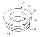
- FIG. 2 is a perspective view of a seal case of the motor with a seal member in one embodiment.
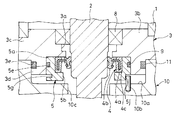
- FIG. 3 is a partially enlarged vertical cross-sectional view of the seal member-equipped motor in the embodiment provided with the first modified example of the seal case.
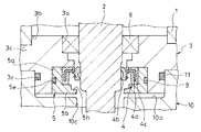
- FIG. 4 is a partially enlarged vertical cross-sectional view of the seal member-equipped motor in an embodiment provided with a spacer.
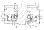
- FIG. 5 is a partially enlarged vertical sectional view of a motor with a seal member in an embodiment provided with a second modification of the seal case.
- FIG. 6 is a partially enlarged vertical sectional view of a motor with a seal member in an embodiment provided with a third modification of the seal case.
- FIG. 7 is a partially enlarged vertical sectional view of a motor with a seal member in an embodiment provided with a fourth modification of the seal case.
- the motor M with a seal member in one embodiment is a case 1 for housing the stator S and the rotor R, and an insertion case in which the output shaft 2 in the rotor R is inserted while being attached to the case 1
- a lid member 3 having a hole 3a, an annular seal member 4 for sealing the outer periphery of the output shaft 2, and a seal case 5 which holds the seal member 4 and which is removable on the opposite case 1 side of the lid member 3 .
- the case 1 is a cylinder whose one end is closed, and an annular stator S is mounted on the inner periphery, and a rotor R inserted inside the stator S is accommodated. ing.
- the rotor R includes the output shaft 2, a cylindrical yoke 6 mounted on the outer periphery of the output shaft 2, and a plurality of magnets 7 serving as a field mounted on the outer periphery of the yoke 6.
- the stator S is not shown in detail, but includes a core which is cylindrical and has a plurality of slots and faces the outer periphery of the magnet 7 of the rotor R, and a winding wound around each slot of the core It is configured and fixed to the inner periphery of the case 1.
- the magnet R is provided on the rotor R side
- the stator S of the armature is provided on the case 1 side
- the motor M with a seal member is a brushless motor.
- a motor with a brush having a field of S may be used.
- the open end 1 a of the case 1 is closed by a lid member 3 provided with an insertion hole 3 a for permitting insertion of the output shaft 2.
- the lid member 3 has a fitting portion 3b fitted to the inner periphery of the opening end 1a of the case 1, and a flange portion 3c larger in diameter than the fitting portion 3b and abutting on the end face of the opening end 1a of the case 1 And an annular accommodating portion 3d which rises from the side opposite to the case 1 which is the lower side in FIG. 1 of the flange portion 3c, and an insertion hole 3a which is open from the fitting portion 3b and which leads inside from the accommodating portion 3d of the flange portion 3c. ing.
- the lid member 3 is fixed to the case 1, and a ball bearing 8 for rotatably supporting the output shaft 2 is mounted on the inner periphery of the insertion hole 3a.
- the output shaft 2 has one end through the insertion hole 3a. The other end is rotatably supported by a ball bearing (not shown) fixed in the case 1 and is allowed to rotate around the axis with respect to the case 1. Therefore, the rotor R is rotatable in the circumferential direction about the output shaft 2 with respect to the stator S, and is rotationally driven when electricity is supplied to the winding of the stator S of the seal member-equipped motor M.
- the inner diameter of the housing portion 3d in the lid member 3 is larger than the inner diameter of the opening on the side opposite to the case 1 of the insertion hole 3a, and the sealing member 4 and the sealing member 4 are housed in the housing portion 3d.
- the seal case 5 to hold is accommodated.
- An O-ring 11 is mounted in an annular groove 3 e provided on the outer periphery of the housing 3 d of the lid member 3.
- the seal member 4 is annularly provided on the inner periphery of the annular core metal 4 a having an L-shaped cross section and the core metal 4 a and is in sliding contact with the outer periphery of the output shaft 2 to allow rotation around the axis of the output shaft 2
- An inner peripheral seal portion 4b for sealing the outer periphery of the shaft 2 and an annular outer peripheral seal portion 4c provided on the entire outer periphery of the core 4a are provided.
- the seal case 5 has a cylindrical portion 5 a in which the seal member 4 is fitted on the inner periphery and also fitted on the inner periphery of the accommodation portion 3 d of the lid member 3.
- the inner peripheral flange 5b is smaller in inner diameter than the cylindrical portion 5a connected to the side opposite to the seal member 4 and is opposite to the side opposite to the seal member 4 of the seal member 4, and radially protrudes from the outer periphery of the end of the inner peripheral flange 5b.
- an outer peripheral flange portion 5c is formed in a D shape having a cutout portion 5d as a recessed portion in a part of a circle, and the outer diameter thereof is larger than the outer diameter of the cylindrical portion 5a.
- annular groove 5e is provided on the outer periphery of the cylindrical portion 5a, and an O-ring 9 is mounted in the annular groove 5e.
- the seal case 5 configured in this manner holds the seal member 4 fitted to the inner periphery of the cylindrical portion 5 a and inserts the output shaft 2 inward from the tip end of the lid member 3 while holding the seal member 4. It is fitted in the annular accommodating portion 3d and mounted on the lid member 3 on the side opposite to the case 1 which is the lower side in FIG.
- the inner peripheral seal portion 4 b of the seal member 4 is in sliding contact with the outer periphery of the output shaft 2, the outer peripheral seal portion 4 c of the seal member 4 is in close contact with the inner periphery of the cylindrical portion 5 a of the seal case 5.
- the O-ring 9 mounted on the case 5 is in close contact with the inner periphery of the housing 3 d of the lid member 3.
- a gap g is formed between the end of the housing portion 3d opposite to the case 1 and the outer peripheral flange portion 5c. That is, in this example, the axial length from the seal member 4 side end of the cylindrical portion 5a of the seal case 5 in the seal case 5 to the seal member 4 side end of the outer peripheral flange portion 5c is greater than the axial length of the accommodation portion 3d Even if the seal case 5 is fitted in the housing 3d and the end of the cylindrical portion 5a abuts on the flange 3c of the lid member 3, the gap g is always formed.
- the seal case 5 can be removed from the lid member 3 by pulling out the lid member 3 using the outer peripheral flange portion 5c. Therefore, in the present embodiment, the outer peripheral flange portion 5 c functions as a drawing portion of the seal case 5.
- the seal case 5 is detachably attached to the lid member 3.
- the motor M with a seal member configured as described above is mounted on a hydraulic pump P as a driven device and used to drive the hydraulic pump P. Then, the housing portion 3d of the cover member 3 of the seal member-equipped motor M is inserted into the fitting recess 10a of the motor connecting member 10 to which the hydraulic pump P is attached, and the connection between the seal member-equipped motor M and the hydraulic pump P is It is designed.
- the tip of the output shaft 2 is a drive shaft of the hydraulic pump P through a coupling 12 accommodated in a shaft insertion hole 10c that opens from the inside of the fitting recess 10a in the motor connection member 10 and leads to the opposite side. It is linked to 13.
- the hydraulic pump P includes a casing 14, a drive shaft 13 and a driven shaft 15 rotatably held by the casing 14, a gear 16 accommodated in the casing 14 and provided on the outer periphery of the drive shaft 13, and the inside of the casing 14 And a gear 17 provided on the outer periphery of the driven shaft 15 and meshing with the gear 16. Therefore, in the hydraulic pump P of this example, when the output shaft 2 is rotated by driving the seal member-equipped motor M, this rotation is transmitted to the drive shaft 13 of the hydraulic pump P, and the gears 16 and 17 are rotationally driven. It is considered as a gear pump which discharges the oil drawn in from the suction opening which is not shown from the discharge opening which is not illustrated.
- the driven device may be a hydraulic pressure pump other than the gear pump, or may be an apparatus other than the hydraulic pressure pump.
- the motor connecting member 10 is provided with a pin 10b as a projection that rises from the bottom of the fitting recess 10a.
- the pin 10b is inserted into the notch 5d of the outer peripheral flange 5c of the seal case 5 and is opposed thereto, and when the seal case 5 tries to rotate about the axis with respect to the lid member 3, the pin 10b of the notch 5d is The opposite surface contacts the pin 10 b to restrict the rotation of the seal case 5.
- the rotation stopping portion is configured by including the notch portion 5d as the recess portion provided in the outer peripheral flange portion 5c provided in the seal case 5 and the pin 10b as the projection entering the notch portion 5d ing.
- the O-ring 11 mounted in the annular groove 3e of the housing portion 3d of the lid member 3 is in close contact with the side wall of the fitting recess 10a of the motor coupling member 10 to seal between the motor coupling member 10 and the lid member 3 Ru.
- the oil from the hydraulic pump P side is prevented from leaking from between the motor connecting member 10 and the lid member 3 to the outside.
- the inside of the shaft insertion hole 10c of the motor connecting member 10 communicates with the inside of the hydraulic pump P and is filled with oil so that the pressure in the hydraulic pump P acts, but between the output shaft 2 and the lid member 3 Since the seal member 4 and the O-ring 9 seal, entry of oil into the seal member-equipped motor M is also prevented.
- the seal member 4 is held by the seal case 5 and the seal case 5 is detachably attached to the lid member 3 from the opposite case 1 side.
- the outer periphery of the output shaft 2 is sealed in sliding contact with the outer periphery of the output shaft 2.
- the seal case 5 is removed from the lid member 3 using the above-described tool. Then, the deteriorated seal member 4 may be removed from the seal case 5, and a new seal member 4 may be attached to the seal case 5, and the seal case 5 may be fitted to the lid member 3 again.
- the seal member 4 is held by the seal case 5 and the seal case 5 is mounted on the opposite case 1 side of the lid member 3. There is no need to remove the cover member 3 or disassemble the seal member-equipped motor M, and only the seal member 4 can be replaced. Therefore, according to the motor M with a seal member of the present invention, maintenance work is very easy, and maintenance cost can be reduced.
- the notch 5d and the notch 5d as recesses provided in the outer peripheral flange 5c that restricts the rotation of the seal case 5 about the output shaft 2 with respect to the lid member 3 It has a rotation stopper having a pin 10b as an intruding projection. Therefore, according to the seal member-equipped motor M of this example, even if the seal case 5 is configured to be removable from the lid member 3, the seal case 5 rotates together with the lid member 3 when the output shaft 2 is rotationally driven. And good sealing performance can be exhibited.
- the seal member-equipped motor M When the seal member-equipped motor M is set to rotationally drive the hydraulic pump P in one direction only, the notch 5d of the outer peripheral flange portion 5c is enlarged to provide a clearance between it and the pin 10b. It is also good. Since the seal member-equipped motor M is driven to rotate only in one direction, even if the seal case 5 rotates together with the output shaft 2, when the play is rotated, the outer peripheral flange portion 5c and the pin 10b contact each other. Since the rotation in the same direction can be regulated, it fully functions as a rotation stopper.
- the outer peripheral flange portion 5c having the notch portion 5d as a recessed portion can function not only as the formation of the recessed portion in the rotation stopping portion but also as a drawing out portion used for removing the seal case 5 from the lid member 3.
- the cost of the motor M with a seal member can be reduced as compared with the case where the stopper and the extractor are separately provided independently.
- the rotation stopper is composed of the notch 5d as a recess in the outer peripheral flange 5c and the pin 10b as a protrusion, but the rotation of the seal case 5 with respect to the lid member 3 is other than this. You may try to stop it.
- the seal case 5 is provided with an inner peripheral flange portion 5 b facing the hydraulic pump P side of the seal member 4.
- the inner peripheral flange portion 5b can be omitted, and as shown in FIG. 3, the seal case 5 having the inner peripheral flange portion 5f on the lid member 3 side of the seal member 4 can also be used.
- a washer-like spacer 20 may be interposed between the flange portion 3 c and the seal case 5 in the housing portion 3 d of the lid member 3 while replacing the seal member 4. .
- the spacer 20 when the spacer 20 is provided between the lid member 3 and the seal case 5 in the axial direction of the output shaft 2, the contact surface of the seal member 4 held by the seal case 5 with the outer periphery of the output shaft 2 However, with respect to the contact surface to the outer periphery of the output shaft 2 in the seal member 4 before replacement, it is axially displaced to the hydraulic pump P side. Then, since the new seal member 4 after replacement is in sliding contact with the non-worn outer peripheral surface of the output shaft 2, the replacement of the output shaft 2 is not required, and a good sealing function can be exhibited. If the seal case 5 may interfere with the motor connecting member 10 in order to provide the spacer 20, the seal case 5 may be used which has a short overall length in the axial direction according to the thickness of the spacer 20.
- the seal case 5 is provided with the outer peripheral flange portion (extraction portion) 5 c that enables the lid member 3 to be extracted from the storage portion. , Replacement work of the seal member 4 becomes very easy.
- a groove 5g is provided as a drawing portion. It is also good.
- the groove portion 5g may be annularly provided on the outer periphery of the seal case 5, or may be provided at one or a plurality of places with a width allowing insertion of a tool. If the seal case 5 is configured as described above, the outer peripheral flange portion 5c need not be provided, so the outer diameter of the seal case 5 can be reduced. Therefore, since the material cost of the seal case 5 is low, if the motor M with a seal member is configured as described above, the motor M with a seal member becomes cheaper.
- a notch 5j as a recess into which the pin 10b is inserted is provided on the outer periphery of the seal case 5 on the side opposite to the seal member 4, and the pin 10b as a protrusion and the notch 5j are provided. And may constitute a rotation stopper.
- a notch 5h is provided on the entire periphery or a part of the inner peripheral side of the inner peripheral flange 5b of the seal case 5 as a withdrawal part. Part 5c may be omitted.
- a tool may be inserted not into the outer periphery but into the notch 5 h on the inner periphery, so the seal case 5 does not have to protrude from the lid member 3 to the hydraulic pump P side.
- the inner peripheral flange portion 5b may be used as the extraction portion, as long as the tool is hooked on the inner peripheral flange portion 5b itself and the seal case 5 can be extracted without providing the cutout portion 5h in the inner peripheral flange portion 5b.
- screw holes 5 i extending in the axial direction from the end face of the seal case 5 on the hydraulic pump (driven device) P side are provided as a withdrawal portion, and removal of the seal case 5 from the lid member 3 is At this time, a screw may be screwed into the screw hole 5i and pulled out using the screw. Also in this case, the outer peripheral flange portion 5c can be omitted, and the seal case 5 need not protrude from the lid member 3 to the hydraulic pump P side. Therefore, there is no concern about interference between the seal case 5 and the driven device, and the axial distance between the seal member motor M and the driven device can be set short, so that the entire seal member motor M and the driven device can be compact. Has the advantage of being
- the lower end of the seal case 5 in FIGS. 6 and 7 is flush with the lower end of the accommodation portion 3d of the lid member 3 in FIGS.
- a recessed portion and a protrusion that enters the recessed portion may be provided in any part of the facing surface of the cover, and the recessed portion and the protrusion may constitute a rotation stopping portion to prevent rotation of the seal case 5 with respect to the lid member 3.
- the seal case 5 is simply and inexpensively manufactured.
- the rotation around the output shaft 2 with respect to the lid member 3 can be restricted.
- the rotation stopping portion may be provided on the seal case 5 and the lid member 3 or provided on the seal case 5 and a member attached directly or indirectly to the lid member 3 (in this example, the motor connecting member 10). May be
Landscapes
- Engineering & Computer Science (AREA)
- General Engineering & Computer Science (AREA)
- Mechanical Engineering (AREA)
- Power Engineering (AREA)
- Sealing With Elastic Sealing Lips (AREA)
- Sealing Devices (AREA)
- Motor Or Generator Frames (AREA)
- Hydraulic Motors (AREA)
Abstract
本発明のシール部材付モータ(M)は、ステータ(S)とロータ(R)とを収容するケース(1)と、ケース(1)に装着されるとともにロータ(R)における出力シャフト(2)が挿通される挿通孔(3a)を有する蓋部材(3)と、出力シャフト(2)の外周をシールする環状のシール部材(4)と、シール部材(4)を保持するとともに蓋部材(3)の反ケース(1)側に着脱自在なシールケース(5)とを備えている。
Description
本発明は、シール部材付モータの改良に関する。
油圧ポンプ等の液体を利用する被駆動装置の駆動に利用されるモータは、ステータとロータとを収容するケース内へ被駆動装置側から液体の侵入を防ぐために、ロータにおける出力シャフトの外周をシールするシール部材を備えている。
このようなシール部材付モータは、たとえば、JP2002-180975Aに開示されているように、ステータとロータとを収容するケースの開口部を閉塞する端壁に環状のシール部材を装着するものがある。より詳細には、シール部材付モータにおける端壁には、出力シャフトの挿通を許容する挿通孔が設けられており、端壁における挿通孔の内周に出力シャフトを回転支持するボールベアリングとボールベアリングの被駆動装置側に配置されるシール部材がそれぞれ装着されている。
このようにシール部材が端壁によって保持されて出力シャフトの外周に摺接しており、出力シャフトの外周がシールされるので、被駆動装置側からケース内への液体の侵入が防止される。
前述のようにシール部材を備えたシール部材付モータにおいて、シール部材は、回転する出力シャフトに常に摺接して摩耗するため消耗が激しく、シール部材付モータを構成する他部品に比較して頻繁に交換しなければならない部品の一つである。
シール部材の交換にあたり、出力シャフトを挿通孔から引き抜きケースから端壁を取り外すシール部材付モータの分解作業が必須である。さらに、シール部材付モータの分解後に、端壁ごとシール部材を交換するか、端壁からボールベアリングとシール部材を引き抜いてシール部材のみを交換する必要がある。このように、前述の従来のシール部材付モータでは、シール部材を端壁から取り外して交換するのは、非常に面倒な作業となっている。
したがって、従来のシール部材付モータでは、メンテナンス作業が非常に面倒であるとともに時間が掛かるためメンテナンスコストも高かった。
そこで、本発明は、メンテナンス作業が容易でメンテナンスコストを低減できるシール部材付モータの提供を目的としている。
上記した目的を達成するため、本発明におけるシール部材付モータにあっては、シール部材がシールケースに保持されてシールケースが蓋部材の反ケース側に着脱自在な構造としているので、シール部材の交換に際してシール部材付モータを分解する必要がなく、シール部材のみを交換できる。
以下、図に示した実施の形態に基づき、本発明を説明する。図1に示すように、一実施の形態におけるシール部材付モータMは、ステータSとロータRとを収容するケース1と、ケース1に装着されるとともにロータRにおける出力シャフト2が挿通される挿通孔3aを有する蓋部材3と、出力シャフト2の外周をシールする環状のシール部材4と、シール部材4を保持し蓋部材3の反ケース1側に着脱自在なシールケース5とを備えている。
以下、シール部材付モータMの各部について詳しく説明する。図1に示すように、ケース1は、一端が閉塞される筒体であって、内周には、環状のステータSが装着されるとともに、ステータSの内側に挿通されるロータRを収容している。
ロータRは、本例では、出力シャフト2と、出力シャフト2の外周に装着される筒状のヨーク6と、ヨーク6の外周に装着される界磁となる複数の磁石7とを備えている。
ステータSは、詳細には図示しないが、円筒状であって複数のスロットを備えてロータRの磁石7の外周に対向するコアと、コアの各スロットに巻回される巻線とを備えて構成されており、ケース1の内周に固定されている。
本例では、ロータR側に磁石7を備え、ケース1側に電機子のステータSを備えており、シール部材付モータMは、ブラシレスモータとされているが、ロータR側を電機子としてステータSを界磁とするブラシ付きのモータとされてもよい。
そして、ケース1の開口端1aは、出力シャフト2の挿通を許容する挿通孔3aを備えた蓋部材3によって閉塞されている。蓋部材3は、ケース1の開口端1aの内周に嵌合される嵌合部3bと、嵌合部3bより大径であってケース1の開口端1aの端面に当接するフランジ部3cと、フランジ部3cの図1中下方側となる反ケース1側から立ち上がる環状の収容部3dと、嵌合部3bから開口してフランジ部3cの収容部3dより内側に通じる挿通孔3aとを備えている。
蓋部材3は、ケース1に固定されており、挿通孔3aの内周には、出力シャフト2を回転支持するボールベアリング8が装着されている、出力シャフト2は、一端が挿通孔3aを介してケース1外へ突出されており、他端が図示はしないがケース1内に固定されるボールベアリングによって回転支持され、ケース1に対して軸周りの回転が許容されている。よって、ロータRは、出力シャフト2を中心としてステータSに対して周方向へ回転可能とされており、シール部材付モータMのステータSの巻線へ通電すると回転駆動される。
戻って、蓋部材3における収容部3dの内径は、挿通孔3aの反ケース1側の開口の内径よりも大径とされており、収容部3d内には、シール部材4とシール部材4を保持するシールケース5が収容されている。なお、蓋部材3の収容部3dの外周に設けた環状溝3e内にはOリング11が装着されている。
シール部材4は、断面L字の環状の芯金4aと、芯金4aの内周に環状に設けられて出力シャフト2の外周に摺接して出力シャフト2の軸周りの回転を許容しつつ出力シャフト2の外周をシールする内周シール部4bと、芯金4aの外周全周に設けた環状の外周シール部4cとを備えている。
シールケース5は、図1および図2に示すように、内周にシール部材4が嵌合されるとともに蓋部材3の収容部3dの内周に嵌合される筒部5aと、筒部5aの反シール部材4側に連なる筒部5aより内径が小径でシール部材4の反シール部材4側に対向する内周フランジ部5bと、内周フランジ部5bの端部外周から径方向へ突出する外周フランジ部5cとを備えている。また、外周フランジ部5cは、円の一部に凹部としての切欠部5dを有するD形状とされており、その外径が筒部5aの外径よりも大径とされている。
シールケース5の筒部5a内にシール部材4が嵌合されると、摩擦力によってシール部材4がシールケース5に対して保持される。シール部材4と出力シャフト2の間の摩擦力は、シール部材4とシールケース5との間の摩擦力に比して小さいので、シールケース5が出力シャフト2に対して回転しない限りにおいてシール部材4が出力シャフト2と共に回転しないようになっている。
また、筒部5aの外周には、環状溝5eが設けられていて、この環状溝5e内にはOリング9が装着されている。そして、このように構成されたシールケース5は、筒部5aの内周に嵌合されるシール部材4を保持した状態で、出力シャフト2を先端側から内方に挿通させつつ蓋部材3の環状の収容部3d内に嵌合させて蓋部材3に図1中下方側となる反ケース1側に装着される。すると、出力シャフト2の外周にはシール部材4の内周シール部4bが摺接し、シールケース5の筒部5aの内周にはシール部材4の外周シール部4cが密着し、さらには、シールケース5に装着されたOリング9が蓋部材3の収容部3dの内周に密着する。このように、シール部材4とOリング9とで出力シャフト2と蓋部材3との間がシールされてシール部材付モータMの内部が液密に密閉される。また、シールケース5は、内周フランジ部5bを備えているので、シール部材4のシールケース5からの脱落と、シール部材4の軸方向移動が防止されている。
また、シールケース5を収容部3dに装着した状態では、収容部3dの反ケース1側端と外周フランジ部5cとの間に工具を挿入可能な隙間gが形成されている。つまり、本例では、シールケース5におけるシールケース5の筒部5aのシール部材4側端から外周フランジ部5cのシール部材4側端までの軸方向長さは、収容部3dの軸方向長さよりも長くなっており、シールケース5を収容部3d内に嵌合して筒部5aの端部が蓋部材3のフランジ部3cに当接しても必ず隙間gが形成される。
よって、シールケース5を蓋部材3の収容部3dに嵌合しても、前記隙間gにドライバ等の工具を差し込んで外周フランジ部5cに当てがい、工具を捻る或いは梃の要領で外周フランジ部5cへ蓋部材3から離間させる力を作用させ得る。このように、外周フランジ部5cを利用してシールケース5が蓋部材3を引き抜いて、シールケース5を蓋部材3から取り外しできる。したがって、本例では、外周フランジ部5cがシールケース5の引き抜き部として機能している。このように、シールケース5は、蓋部材3に着脱可能とされている。
このように構成されたシール部材付モータMは、本例では、被駆動装置としての油圧ポンプPに装着されて油圧ポンプPの駆動に利用される。そして、シール部材付モータMの蓋部材3の収容部3dを油圧ポンプPが取り付けられたモータ連結部材10の嵌合凹部10aに挿入して、シール部材付モータMと油圧ポンプPとの連結が図られている。なお、出力シャフト2の先端は、モータ連結部材10における嵌合凹部10aの内方から開口して反対側へ通じるシャフト挿通孔10c内に収容されるカップリング12を介して油圧ポンプPの駆動軸13に連結されている。油圧ポンプPは、ケーシング14と、ケーシング14に回転自在に保持される駆動軸13および従動軸15と、ケーシング14内に収容されるとともに駆動軸13の外周に設けたギヤ16と、ケーシング14内に収容されるともに従動軸15の外周に設けられてギヤ16に歯合するギヤ17とを備えて構成されている。したがって、本例の油圧ポンプPは、シール部材付モータMを駆動して出力シャフト2が回転すると、この回転が油圧ポンプPの駆動軸13に伝達されてギヤ16,17が回転駆動されて図示しない吸込口から吸い込んだ油を図示しない吐出口から吐出するギヤポンプとされている。なお、被駆動装置は、ギヤポンプ以外の液圧ポンプであってもよいし、液圧ポンプ以外の装置であってもよい。
戻って、モータ連結部材10は、嵌合凹部10aにおける底部から立ち上がる突起としてのピン10bを備えている。このピン10bは、シールケース5の外周フランジ部5cの切欠部5dに入り込んで対向しており、シールケース5が蓋部材3に対して軸周りに回転しようとすると切欠部5dのピン10bへの対向面がピン10bに接触してシールケース5の回転を規制する。このように、本例では、シールケース5に設けた外周フランジ部5cに設けた凹部としての切欠部5dと、切欠部5dに入り込む突起としてのピン10bとを有して回転止め部を構成している。
また、蓋部材3の収容部3dの環状溝3eに装着されたOリング11がモータ連結部材10の嵌合凹部10aの側壁に密着してモータ連結部材10と蓋部材3との間がシールされる。よって、油圧ポンプP側からの油がモータ連結部材10と蓋部材3との間から外部へ漏洩しないようになっている。また、モータ連結部材10のシャフト挿通孔10c内は、油圧ポンプP内に通じており、油で満たされて油圧ポンプP内の圧力が作用するが、出力シャフト2と蓋部材3との間がシール部材4とOリング9とでシールされているので、シール部材付モータM内への油の侵入も阻止される。
以上のように、本発明のシール部材付モータMでは、シール部材4がシールケース5に保持されてシールケース5が蓋部材3に反ケース1側から着脱自在とされており、シール部材4が出力シャフト2の外周に摺接して出力シャフト2の外周をシールしている。
このように構成されたシール部材付モータMにあっては、シール部材4が経年劣化して交換を要する場合、前述の工具を利用して蓋部材3からシールケース5を取り外す。そして、劣化したシール部材4をシールケース5から取り外して換わりに新しいシール部材4をシールケース5へ取り付けて、再度、シールケース5を蓋部材3へ嵌合させればよい。前述のように本発明のシール部材付モータMは、シール部材4がシールケース5に保持されてシールケース5が蓋部材3の反ケース1側に装着されているので、シール部材4の交換に際して蓋部材3の取り外しもシール部材付モータMの分解もする必要がなく、シール部材4のみを交換できる。よって、本発明のシール部材付モータMによれば、メンテナンス作業が非常に容易であり、メンテナンスコストをも低減できる。
また、本例のシール部材付モータMにあっては、シールケース5の蓋部材3に対する出力シャフト2周りの回転を規制する外周フランジ部5cに設けた凹部としての切欠部5dと切欠部5dに入り込む突起としてのピン10bとを有する回転止め部を備えている。よって、本例のシール部材付モータMによれば、蓋部材3にシールケース5を着脱自在な構造としても出力シャフト2の回転駆動時にシールケース5が共回りして蓋部材3に対して回転する問題も生じず、良好なシール性能を発揮できる。また、シール部材付モータMが油圧ポンプPを一方向へのみ回転駆動するように設定される場合、外周フランジ部5cの切欠部5dを大きくしてピン10bとの間に遊びを設けておいてもよい。シール部材付モータMが一方向へのみしか回転駆動されないので、シールケース5が出力シャフト2と共回りしても前記遊び分を回転すると外周フランジ部5cとピン10bとが接触してそれ以上の同方向への回転を規制できるので、回転止めとして十分に機能を発揮する。また、凹部としての切欠部5dを有する外周フランジ部5cは、回転止め部における凹部の形成だけでなく、シールケース5の蓋部材3からの取り外しに使用される引き抜き部としても機能できるので、回転止め部と引き抜き部を別個独立して設ける場合と比較してシール部材付モータMのコストを低減できる。なお、本例では、回転止め部は、外周フランジ部5cにおける凹部としての切欠部5dと突起としてのピン10bとで構成されているが、これ以外の構造でシールケース5の蓋部材3に対する回転止めを図ってもよい。
なお、シールケース5がシール部材4の脱落と軸方向移動を防止するために、シール部材4の油圧ポンプP側に対向する内周フランジ部5bを備えている。しかしながら、本例では、油圧ポンプP側からシール部材4の油圧ポンプP側に油圧が作用するため、油圧の作用によってシール部材4の脱落と軸方向移動を防止できるので、このよう場合には、内周フランジ部5bの省略も可能であり、図3に示すように、シール部材4の蓋部材3側に内周フランジ部5fを持つシールケース5の利用も可能である。
シール部材4は、出力シャフト2に対して軸方向へは移動しないため、長期間に亘ってシール部材付モータMを使用すると出力シャフト2の外周がシール部材4との接触によって摩耗する。このような場合、図4に示すように、シール部材4の交換とともに、蓋部材3における収容部3d内におけるフランジ部3cとシールケース5との間にワッシャ状のスペーサ20を介装すればよい。このように、出力シャフト2の軸方向にて、蓋部材3とシールケース5との間にスペーサ20を設けると、シールケース5に保持されたシール部材4の出力シャフト2の外周への接触面が、交換前のシール部材4における出力シャフト2の外周への接触面に対して油圧ポンプP側へ軸方向にずれる。すると、交換後の新しいシール部材4は、出力シャフト2の摩耗していない外周面に摺接するため、出力シャフト2の交換を要せず良好なシール機能を発揮できる。なお、スペーサ20を設けるためにシールケース5がモータ連結部材10と干渉する可能性がある場合には、スペーサ20の厚みに応じて軸方向の全長を短いシールケース5を使用すればよい。
また、本例のシール部材付モータMにあっては、前述したように、シールケース5が蓋部材3の収容部からの引き抜きを可能とする外周フランジ部(引き抜き部)5cを備えているので、シール部材4の交換作業が非常に簡単となる。
工具の利用でシールケース5の蓋部材3から取り外しを可能とするには、図5に示すように、シールケース5に外周フランジ部5cを設ける代わりに、引き抜き部として溝部5gを設けるようにしてもよい。溝部5gは、シールケース5の外周に環状に設けられてもよいし、工具の差し込みが可能な幅で一箇所または複数個所に設けられてもよい。このようにシールケース5を構成すれば、外周フランジ部5cを設けずに済むのでシールケース5の外径を小径にできる。よって、シールケース5の材料費が安価となるので、このようにシール部材付モータMを構成すれば、シール部材付モータMがより安価となる。なお、このように外周フランジ部5cを設けない場合、シールケース5の反シール部材4側の外周部にピン10bが入り込む凹部としての切欠部5jを設けて、突起としてのピン10bと切欠部5jとで回転止め部を構成してもよい。
また、工具の差し込みが可能であれば、図6に示すように、引き抜き部としてシールケース5の内周フランジ部5bの内周側の全周或いは一部に切欠部5hを設けて、外周フランジ部5cを省略してもよい。この場合には、シールケース5の取り外しの際に外周ではなく内周の切欠部5hに工具を差し込めばよいので、シールケース5が蓋部材3から油圧ポンプP側へ突出している必要がなくなる。よって、シールケース5と被駆動装置との干渉の心配がなくなるとともに、シール部材付モータMと被駆動装置との軸方向距離を短く設定でき、シール部材付モータMと被駆動装置の全体を小型化できる利点がある。なお、内周フランジ部5bに切欠部5hを設けなくとも、内周フランジ部5b自体に工具を引っ掛けてシールケース5の引き抜きが可能であれば、内周フランジ部5bを引き抜き部としてもよい。
さらに、図7に示すように、引き抜き部としてシールケース5の油圧ポンプ(被駆動装置)P側の端面から軸方向へ延びる螺子孔5iを設けて、シールケース5の蓋部材3からの取り外しの際に、螺子孔5iに螺子を螺合させて螺子を利用して引き抜くようにしてもよい。この場合も外周フランジ部5cを省略でき、シールケース5が蓋部材3から油圧ポンプP側へ突出している必要がなくなる。よって、シールケース5と被駆動装置との干渉の心配がなくなるとともに、シール部材付モータMと被駆動装置との軸方向距離を短く設定でき、シール部材付モータMと被駆動装置の全体を小型化できる利点がある。
図6および図7に示した態様では、シールケース5の図6、7中下端が蓋部材3の収容部3dの図6、7中下端と面一となるので、シールケース5と蓋部材3の対向面の何処かに凹部とこの凹部に入り込む突起を設けて、これら凹部と突起とで回転止め部を構成してシールケース5の蓋部材3に対する回転止めを図ってもよい。
回転止め部がシールケース5に設けた凹部と前記凹部に入り込む突起、或いは、シールケース5に設けた突起と前記突起が入り込む凹部とを備えて構成される場合、簡単且つ安価にシールケース5の蓋部材3に対する出力シャフト2の周りの回転を規制できる。
なお、回転止め部は、シールケース5と蓋部材3とに設けてもよいし、シールケース5と蓋部材3に直接あるいは間接に取り付けられる部材(本例ではモータ連結部材10)とに設けられてもよい。
以上、本発明の好ましい実施の形態を詳細に説明したが、特許請求の範囲から逸脱しない限り、改造、変形及び変更が可能である。
本願は、2017年8月14日に日本国特許庁に出願された特願2017-156388に基づく優先権を主張し、この出願の全ての内容は参照により本明細書に組み込まれる。
Claims (5)
- シール部材付モータであって、
ステータとロータとを収容するケースと、
前記ケースに装着されるとともに前記ロータにおける出力シャフトが挿通される挿通孔を有する蓋部材と、
前記出力シャフトの外周をシールする環状のシール部材と、
前記シール部材を保持するとともに、前記蓋部材の反ケース側に着脱自在なシールケースとを備えた
シール部材付モータ。 - 請求項1に記載のシール部材付モータであって、
前記シールケースの前記蓋部材に対する前記出力シャフトの周りの回転を規制する回転止め部を備えた
シール部材付モータ。 - 請求項2に記載のシール部材付モータであって、
前記回転止め部は、前記シールケースに設けた凹部と前記凹部に入り込む突起を有するか、或いは、シールケースに設けた突起と前記突起が入り込む凹部を有する
シール部材付モータ。 - 請求項1に記載のシール部材付モータであって、
前記出力シャフトの軸方向における前記蓋部材と前記シールケースとの間にスペーサを介装可能とした
シール部材付モータ。 - 請求項1に記載のシール部材付モータであって、
前記蓋部材は、前記シールケースの反ケース側からの嵌合を許容し前記シールケースを収容する環状の収容部を有し、
前記シールケースは、前記収容部からの引き抜きを可能とする引き抜き部を有する
シール部材付モータ。
Applications Claiming Priority (2)
| Application Number | Priority Date | Filing Date | Title |
|---|---|---|---|
| JP2017-156388 | 2017-08-14 | ||
| JP2017156388A JP2019037053A (ja) | 2017-08-14 | 2017-08-14 | シール部材付モータ |
Publications (1)
| Publication Number | Publication Date |
|---|---|
| WO2019035302A1 true WO2019035302A1 (ja) | 2019-02-21 |
Family
ID=65362361
Family Applications (1)
| Application Number | Title | Priority Date | Filing Date |
|---|---|---|---|
| PCT/JP2018/026650 Ceased WO2019035302A1 (ja) | 2017-08-14 | 2018-07-17 | シール部材付モータ |
Country Status (2)
| Country | Link |
|---|---|
| JP (1) | JP2019037053A (ja) |
| WO (1) | WO2019035302A1 (ja) |
Citations (4)
| Publication number | Priority date | Publication date | Assignee | Title |
|---|---|---|---|---|
| JPS5128996A (en) * | 1974-09-06 | 1976-03-11 | Otake Tsuneo | Kogatasenpakuyokaji keikokuki no yokunadochukubuzai no seizohoho |
| JPS5610645A (en) * | 1979-06-29 | 1981-02-03 | Carrier Corp | Airconditioning equipment and controller for same |
| JPH0733567Y2 (ja) * | 1986-12-12 | 1995-07-31 | 株式会社荏原製作所 | ポンプ駆動用水中電動機の軸シール構造 |
| JPH08159293A (ja) * | 1994-11-30 | 1996-06-21 | Toshiba Corp | 軸封装置 |
-
2017
- 2017-08-14 JP JP2017156388A patent/JP2019037053A/ja active Pending
-
2018
- 2018-07-17 WO PCT/JP2018/026650 patent/WO2019035302A1/ja not_active Ceased
Patent Citations (4)
| Publication number | Priority date | Publication date | Assignee | Title |
|---|---|---|---|---|
| JPS5128996A (en) * | 1974-09-06 | 1976-03-11 | Otake Tsuneo | Kogatasenpakuyokaji keikokuki no yokunadochukubuzai no seizohoho |
| JPS5610645A (en) * | 1979-06-29 | 1981-02-03 | Carrier Corp | Airconditioning equipment and controller for same |
| JPH0733567Y2 (ja) * | 1986-12-12 | 1995-07-31 | 株式会社荏原製作所 | ポンプ駆動用水中電動機の軸シール構造 |
| JPH08159293A (ja) * | 1994-11-30 | 1996-06-21 | Toshiba Corp | 軸封装置 |
Also Published As
| Publication number | Publication date |
|---|---|
| JP2019037053A (ja) | 2019-03-07 |
Similar Documents
| Publication | Publication Date | Title |
|---|---|---|
| US10746172B2 (en) | Drive device | |
| JP6697871B2 (ja) | ギアモータ組立体のギアボックス | |
| KR102583871B1 (ko) | 낚시용 릴 | |
| CN105526160A (zh) | 齿轮泵 | |
| EA030874B1 (ru) | Линейный электромеханический привод | |
| CN108291663A (zh) | 电动阀 | |
| WO2015181900A1 (ja) | 回転電機 | |
| JP5545318B2 (ja) | 回転電機 | |
| JP5063514B2 (ja) | 軸封装置 | |
| WO2019035302A1 (ja) | シール部材付モータ | |
| JP2010048353A (ja) | クラッチ機構、クラッチ付減速機、および減速機付モータ | |
| US8836189B2 (en) | Spindle motor having lubricant filled bearing clearance | |
| CN108474380A (zh) | 无油螺杆压缩机 | |
| KR101956326B1 (ko) | 내부 모터 설치형 윈치 장치 | |
| JP2006320151A (ja) | ギヤードモータ | |
| US10385917B2 (en) | Motor | |
| JP2010048352A (ja) | クラッチ機構、クラッチ付減速機、および減速機付モータ | |
| JP2014180117A (ja) | 回転電機 | |
| US20230184335A1 (en) | Pin locking device for a sealing component of a seal cartridge assembly and method for assembling the seal cartridge | |
| JP2008185146A (ja) | 偏心軸の軸封構造およびポンプ装置 | |
| KR20170131793A (ko) | 감속기능이 구비된 진공청소기용 코드릴 조립체 | |
| JP2021143703A (ja) | シール機構及びオイルシールの交換方法 | |
| JP3999163B2 (ja) | 魚釣用電動リール | |
| JP2827935B2 (ja) | 歯車ポンプの軸封装置 | |
| JPH10225054A (ja) | 減速機付き電動機 |
Legal Events
| Date | Code | Title | Description |
|---|---|---|---|
| 121 | Ep: the epo has been informed by wipo that ep was designated in this application |
Ref document number: 18847128 Country of ref document: EP Kind code of ref document: A1 |
|
| NENP | Non-entry into the national phase |
Ref country code: DE |
|
| 122 | Ep: pct application non-entry in european phase |
Ref document number: 18847128 Country of ref document: EP Kind code of ref document: A1 |