WO2019030982A1 - Procédé de commande de dispositif de vibration et dispositif de vibration - Google Patents
Procédé de commande de dispositif de vibration et dispositif de vibration Download PDFInfo
- Publication number
- WO2019030982A1 WO2019030982A1 PCT/JP2018/015236 JP2018015236W WO2019030982A1 WO 2019030982 A1 WO2019030982 A1 WO 2019030982A1 JP 2018015236 W JP2018015236 W JP 2018015236W WO 2019030982 A1 WO2019030982 A1 WO 2019030982A1
- Authority
- WO
- WIPO (PCT)
- Prior art keywords
- light transmitting
- piezoelectric element
- transmitting body
- sweep
- frequency
- Prior art date
Links
- 238000000034 method Methods 0.000 title claims abstract description 44
- 238000010408 sweeping Methods 0.000 claims abstract description 19
- 239000007788 liquid Substances 0.000 claims abstract description 18
- 238000000889 atomisation Methods 0.000 claims abstract description 17
- 230000003247 decreasing effect Effects 0.000 claims description 4
- XLYOFNOQVPJJNP-UHFFFAOYSA-N water Substances O XLYOFNOQVPJJNP-UHFFFAOYSA-N 0.000 description 14
- 238000010586 diagram Methods 0.000 description 11
- 238000006073 displacement reaction Methods 0.000 description 9
- 238000005259 measurement Methods 0.000 description 9
- 230000005540 biological transmission Effects 0.000 description 4
- 230000005284 excitation Effects 0.000 description 3
- 230000006870 function Effects 0.000 description 3
- 230000000007 visual effect Effects 0.000 description 3
- 239000007767 bonding agent Substances 0.000 description 2
- 239000000919 ceramic Substances 0.000 description 2
- 238000012508 change request Methods 0.000 description 2
- 239000003595 mist Substances 0.000 description 2
- 102220646157 Actin-like protein 7A_S12A_mutation Human genes 0.000 description 1
- 230000007423 decrease Effects 0.000 description 1
- 239000011521 glass Substances 0.000 description 1
- 230000005764 inhibitory process Effects 0.000 description 1
- 230000002093 peripheral effect Effects 0.000 description 1
- 239000011347 resin Substances 0.000 description 1
- 229920005989 resin Polymers 0.000 description 1
- 102200048773 rs2224391 Human genes 0.000 description 1
Images


Classifications
-
- G—PHYSICS
- G02—OPTICS
- G02B—OPTICAL ELEMENTS, SYSTEMS OR APPARATUS
- G02B27/00—Optical systems or apparatus not provided for by any of the groups G02B1/00 - G02B26/00, G02B30/00
- G02B27/0006—Optical systems or apparatus not provided for by any of the groups G02B1/00 - G02B26/00, G02B30/00 with means to keep optical surfaces clean, e.g. by preventing or removing dirt, stains, contamination, condensation
-
- H—ELECTRICITY
- H02—GENERATION; CONVERSION OR DISTRIBUTION OF ELECTRIC POWER
- H02N—ELECTRIC MACHINES NOT OTHERWISE PROVIDED FOR
- H02N2/00—Electric machines in general using piezoelectric effect, electrostriction or magnetostriction
- H02N2/02—Electric machines in general using piezoelectric effect, electrostriction or magnetostriction producing linear motion, e.g. actuators; Linear positioners ; Linear motors
- H02N2/026—Electric machines in general using piezoelectric effect, electrostriction or magnetostriction producing linear motion, e.g. actuators; Linear positioners ; Linear motors by pressing one or more vibrators against the driven body
-
- B—PERFORMING OPERATIONS; TRANSPORTING
- B08—CLEANING
- B08B—CLEANING IN GENERAL; PREVENTION OF FOULING IN GENERAL
- B08B17/00—Methods preventing fouling
- B08B17/02—Preventing deposition of fouling or of dust
-
- B—PERFORMING OPERATIONS; TRANSPORTING
- B08—CLEANING
- B08B—CLEANING IN GENERAL; PREVENTION OF FOULING IN GENERAL
- B08B7/00—Cleaning by methods not provided for in a single other subclass or a single group in this subclass
- B08B7/02—Cleaning by methods not provided for in a single other subclass or a single group in this subclass by distortion, beating, or vibration of the surface to be cleaned
-
- G—PHYSICS
- G03—PHOTOGRAPHY; CINEMATOGRAPHY; ANALOGOUS TECHNIQUES USING WAVES OTHER THAN OPTICAL WAVES; ELECTROGRAPHY; HOLOGRAPHY
- G03B—APPARATUS OR ARRANGEMENTS FOR TAKING PHOTOGRAPHS OR FOR PROJECTING OR VIEWING THEM; APPARATUS OR ARRANGEMENTS EMPLOYING ANALOGOUS TECHNIQUES USING WAVES OTHER THAN OPTICAL WAVES; ACCESSORIES THEREFOR
- G03B17/00—Details of cameras or camera bodies; Accessories therefor
- G03B17/02—Bodies
- G03B17/08—Waterproof bodies or housings
-
- G—PHYSICS
- G03—PHOTOGRAPHY; CINEMATOGRAPHY; ANALOGOUS TECHNIQUES USING WAVES OTHER THAN OPTICAL WAVES; ELECTROGRAPHY; HOLOGRAPHY
- G03B—APPARATUS OR ARRANGEMENTS FOR TAKING PHOTOGRAPHS OR FOR PROJECTING OR VIEWING THEM; APPARATUS OR ARRANGEMENTS EMPLOYING ANALOGOUS TECHNIQUES USING WAVES OTHER THAN OPTICAL WAVES; ACCESSORIES THEREFOR
- G03B17/00—Details of cameras or camera bodies; Accessories therefor
- G03B17/56—Accessories
-
- H—ELECTRICITY
- H04—ELECTRIC COMMUNICATION TECHNIQUE
- H04N—PICTORIAL COMMUNICATION, e.g. TELEVISION
- H04N23/00—Cameras or camera modules comprising electronic image sensors; Control thereof
-
- H—ELECTRICITY
- H04—ELECTRIC COMMUNICATION TECHNIQUE
- H04N—PICTORIAL COMMUNICATION, e.g. TELEVISION
- H04N23/00—Cameras or camera modules comprising electronic image sensors; Control thereof
- H04N23/50—Constructional details
- H04N23/52—Elements optimising image sensor operation, e.g. for electromagnetic interference [EMI] protection or temperature control by heat transfer or cooling elements
-
- G—PHYSICS
- G03—PHOTOGRAPHY; CINEMATOGRAPHY; ANALOGOUS TECHNIQUES USING WAVES OTHER THAN OPTICAL WAVES; ELECTROGRAPHY; HOLOGRAPHY
- G03B—APPARATUS OR ARRANGEMENTS FOR TAKING PHOTOGRAPHS OR FOR PROJECTING OR VIEWING THEM; APPARATUS OR ARRANGEMENTS EMPLOYING ANALOGOUS TECHNIQUES USING WAVES OTHER THAN OPTICAL WAVES; ACCESSORIES THEREFOR
- G03B2205/00—Adjustment of optical system relative to image or object surface other than for focusing
- G03B2205/0053—Driving means for the movement of one or more optical element
- G03B2205/0061—Driving means for the movement of one or more optical element using piezoelectric actuators
-
- H—ELECTRICITY
- H04—ELECTRIC COMMUNICATION TECHNIQUE
- H04N—PICTORIAL COMMUNICATION, e.g. TELEVISION
- H04N23/00—Cameras or camera modules comprising electronic image sensors; Control thereof
- H04N23/50—Constructional details
- H04N23/55—Optical parts specially adapted for electronic image sensors; Mounting thereof
Definitions
- the present invention relates to a driving method and a vibrating device of a vibrating device having a droplet removing function such as water droplets.
- a camera with a raindrop removing function is disclosed.
- a translucent dome-shaped cover is disposed in front of the camera body.
- a cylindrical body is connected to the dome-shaped cover, and a piezoelectric ceramic vibrator is fixed to the cylindrical body.
- the piezoelectric vibrator vibrates the cylinder and the dome-shaped cover. Thereby, the water droplets are atomized and removed.
- the water droplets can be effectively removed by vibrating around the resonance frequency of the dome-shaped cover.
- Patent Document 1 the frequency of the AC voltage is increased to the highest frequency at the time of driving, and thereafter, the vicinity of the resonance frequency is swept so as to lower the frequency.
- Patent Document 1 a method of sweeping with a sawtooth wave pattern A and a pattern B of sweeping around a plurality of resonance frequencies in order of decreasing frequency in order of decreasing frequency after increasing the frequency to the highest frequency And are shown.
- the water droplets may spread like a liquid film, which may damage the field of view of the camera.
- An object of the present invention is to provide a driving method and a vibrating device of a vibrating device which hardly cause the obstruction of the visual field due to the spread of the liquid film when removing the droplets attached to the light transmitting body.
- a vibration device having a light transmitting body and a piezoelectric element connected to the light transmitting body so as to vibrate the light transmitting body
- droplets attached to the light transmitting body are removed by atomization.
- the drive voltage for vibrating the piezoelectric element is swept at a sweep speed of 1 Hz or more and 50 Hz or less so that the frequency of vibration of the piezoelectric element is swept in a frequency range including both resonance frequencies.
- the step of sweeping in the frequency range includes a step of increasing a sweep voltage and a step of decreasing the sweep voltage after a step of increasing the sweep voltage And the sweep voltage is raised and lowered continuously.
- the first piezoelectric element is driven to atomize droplets adhering to the light-transmitting body by sweeping the frequency range. And a second step of vibrating the light transmitting body so as to make the vibration of the light transmitting body weaker than that of the first step, or stopping the vibration, and after the second step. And a third step of atomizing the droplets adhering to the light-transmitting body.
- the vibration device is electrically connected to a light transmitting body, the piezoelectric element which is connected to the light transmitting body, and vibrates the light transmitting body, and is electrically connected to the piezoelectric element.
- the piezoelectric element is vibrated so as to sweep the vibration frequency of the piezoelectric element within a frequency range including the resonant frequency of the light-transmitting body and the resonant frequency of the light-transmitting body when droplets are attached.
- a control circuit for sweeping the driving voltage at a speed of 1 Hz or more and 50 Hz or less.
- the vibration device further includes a cylindrical body connecting the light transmitting body and the piezoelectric element, the piezoelectric element having a ring shape, and the cylindrical body
- the ring-shaped piezoelectric element is fixed to one end side of the cylindrical body, and the light transmitting body is fixed to the other end side of the cylindrical body.
- the driving method of the vibrating device and the vibrating device according to the present invention when removing the droplets attached to the light transmitting member by atomizing, it is difficult for the liquid film to spread on the surface of the light transmitting member. Therefore, when a translucent body is used for a camera cover or the like, the visual field is unlikely to be disturbed.
- FIG. 1 is a schematic front sectional view of a vibration device according to a first embodiment of the present invention.
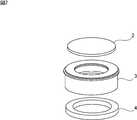
- FIG. 2 is an exploded perspective view showing a vibrating portion of the vibrating device according to the present invention.
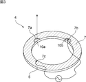
- FIG. 3 is a perspective view for explaining a piezoelectric element used in the vibration device according to the first embodiment.
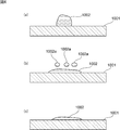
- FIGS. 4 (a) to 4 (c) are schematic front cross-sectional views for explaining the water droplet removing step in the prior art.
- FIGS. 5 (a) to 5 (d) are schematic front cross-sectional views for explaining steps of atomizing droplets in the driving method of the vibrating device according to the embodiment of the present invention.
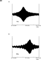
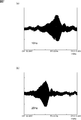
- FIG. 6 (a) and 6 (b) is a figure which shows the change of the displacement amount of the light-transmissive body in case sweep speed is 1 Hz and 5 Hz.
- FIG. 7A and FIG. 7B are diagrams showing changes in displacement of the light-transmissive member when the sweep rate is 10 Hz and 20 Hz.
- FIG. 8 is a diagram showing a change in displacement of the light-transmissive member when the sweep speed is 100 Hz.
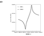
- FIG. 9 is a view showing resonance characteristics in the case where a droplet adheres to the light-transmitting body and in the case where the droplet does not adhere to the light-transmitting body.
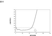
- FIG. 10 is a diagram showing the relationship between the sweep frequency and the required time required for atomization.
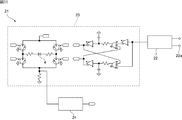
- FIG. 11 is a circuit diagram showing a drive circuit of the vibration device according to the first embodiment of the present invention.
- FIG. 12 is a diagram showing a drive voltage waveform input to the VCO and a magnetic current waveform applied to the piezoelectric element.
- FIG. 13 is a block diagram for explaining a drive circuit of a vibration device according to a second embodiment of the present invention.
- FIG. 14 is a flowchart showing a method of controlling the drive voltage using the control device.
- FIG. 15 is a diagram showing the details of the flowchart in the initial setting step of the flowchart shown in FIG.
- FIG. 16 is a flow chart showing the current maximum value search step in the flow chart shown in FIG.
- FIG. 17 is a diagram showing a flowchart of the sweep process in the flowchart shown in FIG.
- FIG. 1 is a schematic front cross-sectional view for explaining a vibrating device according to a first embodiment of the present invention
- FIG. 2 is an exploded perspective view showing a vibrating portion of the vibrating device.
- the vibration device 1 includes a light transmitting body 2 having a light transmitting property, a cylindrical body 3 and a piezoelectric element 4.
- the cylindrical body 3 has a substantially cylindrical shape.
- a plate-like light transmitting body 2 is fixed to the cylindrical body 3 so as to close an end opening of the cylindrical body 3.
- the light transmitting body 2 is made of light transmitting resin, glass or the like.
- the translucent body 2 is preferably transparent.
- the light transmitting body 2 is fixed to the cylindrical body 3 via the bonding agent layer 5.
- the piezoelectric element 4 has a ring shape.
- the piezoelectric element 4 has a ring-shaped piezoelectric body 6.
- the ring-shaped piezoelectric body 6 is made of piezoelectric ceramic and is polarized in the thickness direction.
- the first electrode 7 is provided on one surface of the ring-shaped piezoelectric body 6, and the second electrode 8 is provided on the other surface.
- the first electrode 7 is provided with notches 7a and 7b.
- the notches 7a and 7b open toward the inner peripheral edge on one surface of the ring-shaped piezoelectric body 6.
- An electrode 10a independent of the first electrode 7 is provided in the notch 7a.
- the electrode 10a functions as a feedback electrode that monitors the voltage generated by the piezoelectric action during vibration.
- An electrode 10b is provided in the notch 7b.
- the electrode 10 b is electrically connected to the second electrode 8 through a part of the inner periphery of the ring-shaped piezoelectric body 6.
- the electrode portion 7c is a part of the first electrode 7, and excites vibration by applying an alternating voltage between the electrode 10b and the electrode portion 7c.
- the electrode 10a as a feedback electrode may not be provided.
- the piezoelectric element 4 vibrates by applying an AC voltage between the first and second electrodes 7 and 8.
- the vibration of the piezoelectric element 4 is transmitted to the cylindrical body 3, and the light transmitting body 2 vibrates together with the cylindrical body 3.
- the water droplet When a droplet such as a water droplet adheres to the light-transmitting body 2, the water droplet can be moved by its vibration and removed by atomization.
- FIGS. 4 (a) to 4 (c) are schematic front cross-sectional views for explaining a water droplet removing step in the case of using a conventional vibrating device as described in Patent Document 1.
- FIG. 4 (a) to 4 (c) are schematic front cross-sectional views for explaining a water droplet removing step in the case of using a conventional vibrating device as described in Patent Document 1.
- FIG. 4 (a) to 4 (c) are schematic front cross-sectional views for explaining a water droplet removing step in the case of using a conventional vibrating device as described in Patent Document 1.
- FIG. 4A shows a state in which the droplet 1002 adheres on the light transmitting body 1001.
- the light transmitting body 1001 is vibrated in the conventional vibration device, it is vibrated near the resonance frequency.
- the mist droplets 1002a, 1002a, and 1002a are dispersed and atomized from the droplet 1002, and a part of the droplet 1002 is removed.
- the surface tension of the droplet 1002 is lowered on the surface of the light transmitting member 1001 and spreads like a liquid film.
- the vibration necessary for atomization is continuously applied, the droplet 1002 spreads in a liquid film as shown in FIG. 4C.
- the droplet 1002 can be removed by atomization.
- the droplets 1002 are stuck in a liquid film and spread. Therefore, there is a problem that the field of view of the camera is obstructed.
- the following first step, second step and third step are carried out in order to sweep a driving voltage described later.
- 5 (a) to 5 (d) are schematic front cross-sectional views showing steps of removing droplets by the driving method according to the first embodiment of the present invention.
- the droplet 11 adheres on the light transmitting body 2.
- the vibration device is driven.
- the droplet 11 spreads and the mist droplets 11a, 11a and 11a are partially removed.
- the driving method in order to remove the droplets by atomization, includes the resonant frequency of the light transmitting member in the case where no droplet is attached to the light transmitting member 2 and the resonant frequency of the light transmitting member in the case where it is attached.
- the drive voltage is swept at a sweep rate of 1 Hz or more and 50 Hz or less in a frequency range including both resonance frequencies with the resonance frequency.
- vibrating the light transmitting body 2 weaker than in the first step means vibrating so that the amplitude of the light transmitting body 2 and the intensity of the vibration become weak.
- the vibration of the light transmitting body 2 may be stopped in the second step.
- the translucent body 2 is vibrated by vibration stronger than that in the second step. That is, as the sweep is continued, atomization proceeds as shown in FIG. 5 (d). Thus, the droplet 11 is eventually removed.
- the droplets 11 are less likely to be attached in the form of a liquid film on the translucent body 2 in the atomizing step.
- the field of view of the camera is less likely to be disturbed.
- the sweep speed is 1 Hz or more and 50 Hz or less when sweeping the frequency range. This will be described with reference to FIGS. 6 (a), 6 (b), 7 (a), 7 (b) and 8.
- FIGS. 6 (a), 6 (b), 7 (a), 7 (b) and 8 the light-transmissive body 2 in the case of a sweep rate of 1 Hz, 5 Hz, 10 Hz, 20 Hz or 100 Hz, respectively. It is a figure which shows the time change of displacement amount, ie, a displacement signal.
- the sweep speed was changed in the same manner as in FIGS. 6 to 8 to obtain the time required for atomization.
- the horizontal axis of FIG. 10 shows the frequency which is the sweep speed, and the vertical axis is the necessary time required to remove the 5 ⁇ l water droplet as a droplet.
- the time required for atomization is rapidly increased. Further, it can be seen from FIG. 10 that the time required for atomization is as short as 10 seconds or less if the frequency is in the range of 1 Hz to 50 Hz, and therefore the water droplets can be effectively atomized.
- FIG. 9 is a diagram showing resonance characteristics in a state in which a droplet is attached to the light-transmitting body 2 and a state in which the droplet is not attached. As shown in FIG. 9, the resonant frequency differs depending on whether the droplet is attached or not attached.
- the resonant frequency of the light transmission body 2 in the case where the droplet does not adhere to the light transmission body 2, and the transmission in the case where the droplet adheres As described above, the sweep is performed at a sweep rate of 1 Hz or more and 50 Hz or less in the frequency range including the resonance frequency of the light body 2 and both resonance frequencies. Thereby, as described above, the droplets can be atomized quickly.
- the atomizing step includes a first step of driving the piezoelectric element so as to atomize the droplets adhering to the light transmitting body, and a step of the first step, The second step of vibrating or stopping the vibration so as to weaken the vibration of the light transmitting body 2, and after the second step, vibrate more strongly than the second step and adhere to the light transmitting body 2 And a third step for re-atomizing the droplets. Therefore, as shown in FIG. 5C described above, in the second step, the droplets are unlikely to spread in the form of a liquid film on the surface of the light-transmissive body 2, so that the field of view of the camera and the like is not easily hindered.
- FIG. 11 is a circuit diagram showing an example of the drive circuit 21.
- the drive circuit 21 includes a VCO 22, a driver circuit unit 23, and a current measurement circuit 24.
- VCO 22 By changing the control voltage applied to the control terminal 22 a of the VCO 22, a predetermined voltage signal is transmitted from the VCO 22 to the driver circuit unit 23.
- the driver circuit unit 23 drives the piezoelectric element 4 so as to sweep the predetermined frequency range at the above-described sweep speed.
- the current measuring circuit 24 measures the current flowing to the piezoelectric element 4 and outputs a voltage according to the current value.
- the upper graph portion of FIG. 12 shows a voltage waveform input to the VCO 22. Further, the lower graph portion of FIG. 12 is a view showing a change of the current measured by the current measurement circuit 24.
- the drive voltage is, for example, continuously raised from 1.85 V to 1.90 V, and then lowered continuously from 1.90 V to 1.85 V.
- the sweep is repeated by repeating this.
- the step of sweeping from the lower limit frequency to the upper limit frequency of the sweep frequency range is a step of increasing the sweep voltage and a step of increasing the sweep voltage.
- Lowering the sweep voltage, and the rise and fall of the sweep voltage are performed not continuously but in steps. In this case, since the change in voltage is gentle, it is difficult to cause linking. Therefore, the efficiency of the vibration required for atomization can be increased. That is, as shown in the upper part of FIG. 12, it is desirable to control the input voltage to the VCO so as to have a triangular wave slope and to perform FM modulation to drive the piezoelectric element 4.
- the wave height of the triangular wave defines the frequency change width of the VCO 22, and the central voltage of the triangular wave defines the central frequency of the CVO 22.
- another excitation circuit is configured with the period of the triangular wave as a parameter.
- the current measurement circuit 24 it is desirable to monitor the current in the piezoelectric element 4 by the current measurement circuit 24. Since the maximum value of the current comes near the maximum displacement point where atomization is possible, fixed parameters of the other excitation circuit can be set by using this current signal. Therefore, the movement and atomization of the droplet can be achieved with the optimum parameters in accordance with the amount and number of droplets.
- circuit used for the drive method of the vibration apparatus of this invention is not limited as shown in FIG.
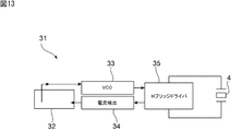
- FIG. 13 is a block diagram for explaining a drive circuit of a vibration device according to a second embodiment of the present invention.
- the drive circuit 31 has a controller 32.
- the controller 32 is connected to the VCO 33 and the current measurement circuit 34.
- the VCO 33 is connected to the H bridge driver 35 as in the case of the circuit shown in FIG.
- the H bridge driver 35 drives the piezoelectric element 4.
- the current measuring circuit 34 can detect the current flowing in the piezoelectric element 4. The detected current value is given to the controller 32.
- the controller 32 has a DA converter and an AD converter.
- the DA converter provides a voltage for controlling the VCO 33.
- the current detected from the current measurement circuit 34 is digitized by the AD converter.
- the drive circuit 31 having the control device 32 may be used.
- control can be performed using a method of adjusting a plurality of parameters. For example, 1) sweep a large frequency range and detect the current peak, 2) drive multiple times with a narrower frequency band centering on the frequency of current peak, 3) return to 1) again and correct the center frequency can do.
- the droplets can be reliably atomized by repeating the above.
- the vibration device 1 of the present embodiment atomization is achieved by the other excitation circuit. Therefore, the visual field inhibition by the liquid film when the self-excitation circuit is used is suppressed.
- the current may be measured by the current measurement circuit 24, or the voltage may be monitored using a feedback electrode.
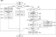
- FIG. 14 is a flowchart showing the entire driving method of the third embodiment. First, in step S1, initialization is performed.
- step S11A parameters are read out from the built-in memory.
- step S12A it is determined whether the parameter of the built-in memory is appropriate. If appropriate, let the initial value of the parameter be the value recorded in the built-in memory. When the built-in memory is not appropriate, a default value predetermined as an initial value of the parameter is adopted. Thus, initialization is finished.
- step S2 it is determined whether there is a request for changing a parameter. If there is a change request, the parameters are changed in step S4. Next, in step S5, the status is set to the current maximum value search state. Next, in step S6, the changed parameter is written to the built-in memory. After step S6, the process returns to step S2 again.
- step S2 when there is no parameter change request, the current maximum value search state or the sweep state is executed in the current status of step S7.
- step S8 executes the processing of the current maximum value search state.
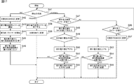
- step S7 when the running state is established, it is determined in step S25 whether or not the timer has expired. If it has expired, the search voltage is output in step S26, the output voltage is read in step S27, and it is determined in step S28 whether the read voltage is greater than adc_max. If so, the search voltage is increased in step S29. In step S30, it is determined whether the search voltage is at the maximum value. In the case of the maximum value, in step S31, the state is changed to the end state. If the search voltage is not the maximum value, the process returns to step S7.
- adc_max is set as the read voltage value in step S32. Then, in step S33, the current search voltage is recorded.
- step S9 it is determined whether the search for the current maximum value is completed. If it has ended, the status is set to the sweep state in step S10. In step S9, when the search for the current maximum value is not completed, the process returns to step S2.
- step S7 if the current status is in the sweeping state, in step S11, the process in the sweeping state is executed.
- a flowchart of the process of this sweeping state is shown in FIG.
- step S45 the sweep frequency range is calculated from the current maximum value.
- step S46 the sweep voltage value is set to the minimum value of the sweep frequency range. More specifically, the sweep voltage value is set to a value corresponding to the minimum value of the sweep frequency range.
- step S41 if it is in the running state, it is determined in step S47 whether or not the sweep voltage change timer has expired. If it has expired, the sweep voltage value is output in step S48, and the direction of the next sweep voltage is determined in step S49. If the direction of the sweep voltage is the direction of lowering the voltage value, the sweep voltage value is lowered in step S50.
- step S51 it is determined whether the sweep voltage value is the minimum value of the sweep frequency range. If it is the minimum value, in step S52, the direction of the sweep voltage value is changed upward.
- step S49 If the direction of the sweep voltage is upward in step S49, the sweep voltage is increased in step S53.
- step S54 it is determined whether the sweep voltage value is the maximum value of the sweep frequency range. If it is the maximum value, in step S55, the direction of the sweep voltage is changed downward. If it is not the maximum value, the process ends.
- step S47 If it is determined in step S47 that the sweep voltage change timer has not expired, it is determined in step S56 whether or not the sweep end timer has expired. If it has expired, the state is changed to finish in step S57, and the process ends. If it is determined in step S56 that the sweep end timer has not expired, the process returns to step S41.
- step S41 in the case of the finish state, the sweep voltage change timer is ended in steps S58 and S59, the state is changed to the initial state, and the process is ended.
- step S11 After the processing of the sweeping state is performed in step S11, it is determined whether or not the sweeping is completed in step S12. If completed, the status is searched for the maximum current value in step S13. I assume. If the sweep has not ended, the process returns to step S2.
- control method shown with reference to FIGS. 14 to 17 is only an example of the control method using the control device in the drive method of the present invention.
Landscapes
- Physics & Mathematics (AREA)
- General Physics & Mathematics (AREA)
- Engineering & Computer Science (AREA)
- Multimedia (AREA)
- Signal Processing (AREA)
- Electromagnetism (AREA)
- Optics & Photonics (AREA)
- Special Spraying Apparatus (AREA)
- Apparatuses For Generation Of Mechanical Vibrations (AREA)
- Camera Bodies And Camera Details Or Accessories (AREA)
- Structure And Mechanism Of Cameras (AREA)
- Accessories Of Cameras (AREA)
- Studio Devices (AREA)
- General Electrical Machinery Utilizing Piezoelectricity, Electrostriction Or Magnetostriction (AREA)
Abstract
L'invention concerne un procédé de commande d'un dispositif de vibration, par lequel le champ de vision est moins susceptible d'être inhibé par l'étalement d'un film liquide au moment de l'élimination de gouttelettes de liquide adhérant à un corps transmettant la lumière. L'invention concerne un procédé de commande d'un dispositif de vibration qui comprend un corps de transmission de lumière (2) et un élément piézoélectrique (4) couplé au corps de transmission de lumière (2) de façon à amener le corps de transmission de lumière (2) à vibrer, le dispositif de vibration étant destiné à éliminer, par atomisation, des gouttelettes de liquide adhérant au corps de transmission de lumière (2), le procédé de commande consistant à : balayer, à une vitesse de balayage de 1 Hz à 50 Hz, une tension de commande pour faire vibrer l'élément piézoélectrique de façon à balayer la fréquence de la vibration de l'élément piézoélectrique dans une plage de fréquences comprenant à la fois une fréquence de résonance du corps de transmission de lumière (2) lorsque aucune gouttelette de liquide n'adhère au corps de transmission de lumière (2) et une fréquence de résonance du corps de transmission de lumière (2) lorsque des gouttelettes de liquide adhèrent à celui-ci.
Priority Applications (4)
| Application Number | Priority Date | Filing Date | Title |
|---|---|---|---|
| EP18843656.2A EP3606029B1 (fr) | 2017-08-09 | 2018-04-11 | Procédé de commande de dispositif de vibration et dispositif de vibration |
| JP2019535587A JP6620914B2 (ja) | 2017-08-09 | 2018-04-11 | 振動装置の駆動方法及び振動装置 |
| CN201880051560.6A CN110999272B (zh) | 2017-08-09 | 2018-04-11 | 振动装置的驱动方法以及振动装置 |
| US16/733,258 US10862405B2 (en) | 2017-08-09 | 2020-01-03 | Method of driving vibration device and vibration device |
Applications Claiming Priority (2)
| Application Number | Priority Date | Filing Date | Title |
|---|---|---|---|
| JP2017154334 | 2017-08-09 | ||
| JP2017-154334 | 2017-08-09 |
Related Child Applications (1)
| Application Number | Title | Priority Date | Filing Date |
|---|---|---|---|
| US16/733,258 Continuation US10862405B2 (en) | 2017-08-09 | 2020-01-03 | Method of driving vibration device and vibration device |
Publications (1)
| Publication Number | Publication Date |
|---|---|
| WO2019030982A1 true WO2019030982A1 (fr) | 2019-02-14 |
Family
ID=65272820
Family Applications (1)
| Application Number | Title | Priority Date | Filing Date |
|---|---|---|---|
| PCT/JP2018/015236 WO2019030982A1 (fr) | 2017-08-09 | 2018-04-11 | Procédé de commande de dispositif de vibration et dispositif de vibration |
Country Status (5)
| Country | Link |
|---|---|
| US (1) | US10862405B2 (fr) |
| EP (1) | EP3606029B1 (fr) |
| JP (1) | JP6620914B2 (fr) |
| CN (1) | CN110999272B (fr) |
| WO (1) | WO2019030982A1 (fr) |
Cited By (4)
| Publication number | Priority date | Publication date | Assignee | Title |
|---|---|---|---|---|
| WO2021038942A1 (fr) * | 2019-08-28 | 2021-03-04 | 株式会社村田製作所 | Dispositif de vibration et dispositif de détection optique |
| US20210302723A1 (en) * | 2020-03-27 | 2021-09-30 | Murata Manufacturing Co., Ltd. | Vibration device and vibration control method |
| CN113891820A (zh) * | 2020-03-19 | 2022-01-04 | 株式会社村田制作所 | 振动装置和振动控制方法 |
| EP3934227A4 (fr) * | 2019-04-26 | 2022-11-09 | Murata Manufacturing Co., Ltd. | Dispositif de nettoyage, unité d'imagerie à dispositif de nettoyage, et procédé de nettoyage |
Families Citing this family (5)
| Publication number | Priority date | Publication date | Assignee | Title |
|---|---|---|---|---|
| JP6597897B2 (ja) * | 2016-06-24 | 2019-10-30 | 株式会社村田製作所 | 振動装置及び撮像装置 |
| CN109643044B (zh) * | 2016-11-30 | 2021-01-01 | 株式会社村田制作所 | 振动装置、摄像机用水滴去除装置以及摄像机 |
| CN114206516B (zh) * | 2020-04-30 | 2023-07-04 | 株式会社村田制作所 | 清洗装置、具备清洗装置的摄像单元以及清洗方法 |
| US20220219381A1 (en) * | 2021-01-08 | 2022-07-14 | Xerox Corporation | Building an object with a three-dimensional printer using vibrational energy |
| JP2023058271A (ja) * | 2021-10-13 | 2023-04-25 | i-PRO株式会社 | 監視カメラ |
Citations (5)
| Publication number | Priority date | Publication date | Assignee | Title |
|---|---|---|---|---|
| JPH08183428A (ja) * | 1995-01-06 | 1996-07-16 | Nippon Sheet Glass Co Ltd | 能動型撥水窓装置 |
| JP2012039754A (ja) * | 2010-08-06 | 2012-02-23 | Canon Inc | 振動発生装置、その駆動方法、異物除去装置および光学装置 |
| JP2012138768A (ja) | 2010-12-27 | 2012-07-19 | Hitachi Kokusai Electric Inc | ドーム型監視カメラシステム |
| JP2013080177A (ja) * | 2011-10-05 | 2013-05-02 | Aisin Seiki Co Ltd | 水滴除去機能付カメラ |
| JP2017085276A (ja) * | 2015-10-26 | 2017-05-18 | オリンパス株式会社 | 液滴排除装置と、液滴排除装置を有する画像装置、及び液滴排除装置の制御方法、液滴排除装置の制御プログラム |
Family Cites Families (7)
| Publication number | Priority date | Publication date | Assignee | Title |
|---|---|---|---|---|
| JPH0295947A (ja) * | 1988-09-30 | 1990-04-06 | Aisin Seiki Co Ltd | 水滴除去装置 |
| AR030524A1 (es) * | 1999-03-05 | 2003-08-27 | Johnson & Son Inc S C | Atomizador de liquido vibratorio |
| JP5430367B2 (ja) * | 2009-11-26 | 2014-02-26 | キヤノン株式会社 | 塵埃除去装置および塵埃除去方法 |
| WO2012129521A1 (fr) * | 2011-03-23 | 2012-09-27 | Gentex Corporation | Dispositif de nettoyage d'objectif |
| CN104069978A (zh) * | 2013-03-25 | 2014-10-01 | 厦门市骏耀光电科技有限公司 | 一种超声波雾化装置及雾化方法 |
| US10401618B2 (en) * | 2015-03-11 | 2019-09-03 | Texas Instruments Incorporated | Ultrasonic lens cleaning system with current sensing |
| GB201510166D0 (en) * | 2015-06-11 | 2015-07-29 | The Technology Partnership Plc | Spray delivery device |
-
2018
- 2018-04-11 CN CN201880051560.6A patent/CN110999272B/zh active Active
- 2018-04-11 JP JP2019535587A patent/JP6620914B2/ja active Active
- 2018-04-11 WO PCT/JP2018/015236 patent/WO2019030982A1/fr unknown
- 2018-04-11 EP EP18843656.2A patent/EP3606029B1/fr active Active
-
2020
- 2020-01-03 US US16/733,258 patent/US10862405B2/en active Active
Patent Citations (5)
| Publication number | Priority date | Publication date | Assignee | Title |
|---|---|---|---|---|
| JPH08183428A (ja) * | 1995-01-06 | 1996-07-16 | Nippon Sheet Glass Co Ltd | 能動型撥水窓装置 |
| JP2012039754A (ja) * | 2010-08-06 | 2012-02-23 | Canon Inc | 振動発生装置、その駆動方法、異物除去装置および光学装置 |
| JP2012138768A (ja) | 2010-12-27 | 2012-07-19 | Hitachi Kokusai Electric Inc | ドーム型監視カメラシステム |
| JP2013080177A (ja) * | 2011-10-05 | 2013-05-02 | Aisin Seiki Co Ltd | 水滴除去機能付カメラ |
| JP2017085276A (ja) * | 2015-10-26 | 2017-05-18 | オリンパス株式会社 | 液滴排除装置と、液滴排除装置を有する画像装置、及び液滴排除装置の制御方法、液滴排除装置の制御プログラム |
Non-Patent Citations (1)
| Title |
|---|
| See also references of EP3606029A4 |
Cited By (7)
| Publication number | Priority date | Publication date | Assignee | Title |
|---|---|---|---|---|
| EP3934227A4 (fr) * | 2019-04-26 | 2022-11-09 | Murata Manufacturing Co., Ltd. | Dispositif de nettoyage, unité d'imagerie à dispositif de nettoyage, et procédé de nettoyage |
| WO2021038942A1 (fr) * | 2019-08-28 | 2021-03-04 | 株式会社村田製作所 | Dispositif de vibration et dispositif de détection optique |
| CN113891820A (zh) * | 2020-03-19 | 2022-01-04 | 株式会社村田制作所 | 振动装置和振动控制方法 |
| US20210302723A1 (en) * | 2020-03-27 | 2021-09-30 | Murata Manufacturing Co., Ltd. | Vibration device and vibration control method |
| CN113767616A (zh) * | 2020-03-27 | 2021-12-07 | 株式会社村田制作所 | 振动装置和振动控制方法 |
| CN113767616B (zh) * | 2020-03-27 | 2023-04-04 | 株式会社村田制作所 | 振动装置和振动控制方法 |
| US11754830B2 (en) * | 2020-03-27 | 2023-09-12 | Murata Manufacturing Co., Ltd. | Vibration device and vibration control method |
Also Published As
| Publication number | Publication date |
|---|---|
| US10862405B2 (en) | 2020-12-08 |
| EP3606029A4 (fr) | 2020-12-16 |
| JP6620914B2 (ja) | 2019-12-18 |
| EP3606029B1 (fr) | 2021-12-15 |
| CN110999272A (zh) | 2020-04-10 |
| JPWO2019030982A1 (ja) | 2019-12-26 |
| US20200144939A1 (en) | 2020-05-07 |
| EP3606029A1 (fr) | 2020-02-05 |
| CN110999272B (zh) | 2021-05-14 |
Similar Documents
| Publication | Publication Date | Title |
|---|---|---|
| JP6620914B2 (ja) | 振動装置の駆動方法及び振動装置 | |
| WO2018198465A1 (fr) | Dispositif de nettoyage et unité de capture d'image pourvue d'un dispositif de nettoyage | |
| US20210018748A1 (en) | Ultrasound Lens Structure Cleaner Architecture and Method Using Standing and Traveling Waves | |
| US11433426B2 (en) | Vibration device and imaging unit including vibration device | |
| JP2007090139A (ja) | 超音波発生装置及び超音波美容装置 | |
| JP2010078824A (ja) | 光走査装置、画像表示装置及び光走査装置の駆動方法 | |
| JP5184909B2 (ja) | 揺動体装置及び光偏向装置 | |
| US11770078B2 (en) | Vibration device and driving device | |
| DE102008050445A1 (de) | Vorrichtung zum Bestimmen und/oder Überwachung einer Prozessgröße eines Mediums | |
| JP2001158109A (ja) | 印刷ヘッド清掃装置 | |
| WO2020003574A1 (fr) | Dispositif d'oscillation et dispositif de détection optique | |
| JP2007311379A (ja) | 超音波洗浄装置 | |
| JP5192270B2 (ja) | 超音波振動子の駆動方法及び装置 | |
| WO2023084843A1 (fr) | Dispositif d'excitation, dispositif de vibration, véhicule, procédé de commande, et programme informatique | |
| JPH05301078A (ja) | 超音波洗浄機の発振回路 | |
| WO2023084829A1 (fr) | Circuit d'excitation, dispositif de vibration et véhicule | |
| KR20130014500A (ko) | 감소된 스페클 콘트라스트를 갖는 마이크로전자기계 시스템 | |
| WO2024084743A1 (fr) | Dispositif optique et unité d'imagerie pourvue d'un dispositif optique | |
| KR102222376B1 (ko) | 액적 제거장치 | |
| JPH0211435A (ja) | 水滴除去装置 | |
| JP3277070B2 (ja) | 超音波洗浄装置及び超音波洗浄方法 | |
| JP2008197139A (ja) | 光走査装置 | |
| JP2020139637A (ja) | 音響滴下除去装置及び音響滴下除去方法 | |
| JP2007052245A (ja) | 画像表示装置及び画像表示方法 | |
| JPH03235742A (ja) | 自動車用ミラーの水滴除去装置 |
Legal Events
| Date | Code | Title | Description |
|---|---|---|---|
| 121 | Ep: the epo has been informed by wipo that ep was designated in this application |
Ref document number: 18843656 Country of ref document: EP Kind code of ref document: A1 |
|
| ENP | Entry into the national phase |
Ref document number: 2019535587 Country of ref document: JP Kind code of ref document: A |
|
| ENP | Entry into the national phase |
Ref document number: 2018843656 Country of ref document: EP Effective date: 20191022 |
|
| NENP | Non-entry into the national phase |
Ref country code: DE |