WO2019026756A1 - 電磁継電器 - Google Patents
電磁継電器 Download PDFInfo
- Publication number
- WO2019026756A1 WO2019026756A1 PCT/JP2018/028085 JP2018028085W WO2019026756A1 WO 2019026756 A1 WO2019026756 A1 WO 2019026756A1 JP 2018028085 W JP2018028085 W JP 2018028085W WO 2019026756 A1 WO2019026756 A1 WO 2019026756A1
- Authority
- WO
- WIPO (PCT)
- Prior art keywords
- movable contact
- piece
- side terminal
- housing
- fixed
- Prior art date
- Legal status (The legal status is an assumption and is not a legal conclusion. Google has not performed a legal analysis and makes no representation as to the accuracy of the status listed.)
- Ceased
Links
Images


Classifications
-
- H—ELECTRICITY
- H01—ELECTRIC ELEMENTS
- H01H—ELECTRIC SWITCHES; RELAYS; SELECTORS; EMERGENCY PROTECTIVE DEVICES
- H01H50/00—Details of electromagnetic relays
- H01H50/54—Contact arrangements
- H01H50/56—Contact spring sets
Definitions
- the present disclosure relates to a multipole electromagnetic relay.
- the electromagnetic relay disclosed in Patent Document 1 includes a rectangular box-shaped housing having an accommodating portion inside, and two fixed contact side terminals and two movable contact side terminals fixed to the housing.
- two fixed contact portions provided to each fixed contact side terminal, two movable contact pieces provided to each movable contact side terminal, and each movable contact piece are provided and each Two movable contact parts arranged to face fixed contact parts, an electromagnet part whose polarity is reversed according to the direction of the supplied current, and one rotation that rotates in different directions according to the polarity of the electromagnet part It is equipped with a block.
- the electromagnetic relay comprises a fixed contact side terminal, a movable contact side terminal and a movable contact piece, and the movable contact piece faces in the base in a direction in which the movable contact portion contacts or separates from the fixed contact portion
- Two circuits arranged are formed.
- Each movable contact piece elastically deforms in a direction approaching each other to bring the movable contact portion into contact with the opposing fixed contact portion, and elastically deforms in the direction away from each other, whereby the movable contact portion opposes the stationary contact It is arranged to be separated from the part.
- an electromagnetic repulsive force is generated in the direction away from each other. That is, an electromagnetic repulsive force may act in the direction in which each movable contact portion is separated from the corresponding fixed contact portion at the time of energization, and the contact reliability of each movable contact portion to the corresponding fixed contact portion may be reduced.
- this indication makes it a subject to provide an electromagnetic relay of a plurality of poles which can improve the contact reliability to the corresponding fixed contact part of each movable contact part.
- the electromagnetic relay is A box-shaped insulating housing having a housing inside; A plate-shaped first fixed contact side terminal fixed to the housing, extending from the outside of the housing to the housing portion, and having a first fixed contact portion located in the housing portion; A plate-shaped first movable contact-side terminal fixed to the housing, extending from the outside of the housing to the housing portion, and electrically disposed with respect to the first fixed contact-side terminal; , The first fixed contact portion is disposed in the housing portion, extends from the first movable contact side terminal toward the first fixed contact side terminal, and is electrically connected to the first movable contact side terminal.
- the housing portion is fixed to the housing, extends from the outside of the housing to the housing portion, and is disposed so as to be electrically independent of the first fixed contact side terminal and the first movable contact side terminal, and the housing portion
- a plate-like second fixed contact side terminal having a second fixed contact portion located in The housing is fixed to the housing and extends from the outside of the housing to the housing portion, and the first stationary contact side terminal, the first movable contact side terminal, and the second stationary contact side terminal are electrically connected.
- the first movable contact piece is disposed in the housing portion adjacent to the first movable contact piece in the thickness direction of the first movable contact piece, extends from the second movable contact side terminal toward the second fixed contact side terminal, and (2) A second movable contact portion electrically connected to the movable contact side terminal and facing the second fixed contact portion, the second movable contact portion being opposed to the second fixed contact portion A plate-like second movable contact piece that elastically deforms in the approaching and separating direction; Equipped with The first movable contact piece extends in a direction intersecting the plate thickness direction and has a first surface provided with the first movable contact portion, and the second movable contact piece and the second movable contact member facing the first surface.
- the second movable contact piece extends in a direction intersecting the plate thickness direction and has a third surface facing at least one of the first movable contact piece and the first movable contact terminal, and the third surface And a fourth surface opposite to and provided with the second movable contact portion,
- the first fixed contact side terminal or the first movable contact side terminal disposed on one side of the extending direction of the first movable contact piece intersecting the contact / separation direction with respect to the first movable contact piece Is a terminal to which current is supplied, and the second fixed contact side terminal or the second fixed contact side terminal disposed on the other side of the extending direction of the first movable contact piece with respect to the second movable contact piece
- the movable contact side terminal is a terminal to which current is supplied.
- the first movable contact piece and the second movable contact piece are provided, and the first movable contact piece extends in the direction intersecting the plate thickness direction and is provided with the first movable contact portion
- a second movable contact piece having a first surface and a second surface opposite to the first surface in the thickness direction and facing at least one of the second movable contact piece and the second movable contact side terminal;
- a third surface extending in a direction intersecting the thickness direction and facing at least one of the first movable contact piece and the first movable contact side terminal, and a third surface facing the third surface in the thickness direction;
- a fourth surface provided with the movable contact portion.
- the directions of the currents flowing through the first movable contact piece and the second movable contact piece are different from each other. Therefore, when power is applied, an electromagnetic repulsive force acts on the first movable contact piece and the second movable contact piece in the direction in which each movable contact portion approaches the corresponding fixed contact portion, and the corresponding fixation of each movable contact portion
- the contact pressure to the contact portion can be increased. As a result, it is possible to improve the contact reliability with respect to the corresponding fixed contact portion of each movable contact portion.
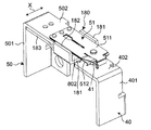
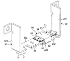
- FIG. 1 is a perspective view of an electromagnetic relay according to an embodiment of the present disclosure.
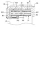
- FIG. 6 is a perspective view for explaining a second magnetic flux collecting piece and a second auxiliary magnetic flux collecting piece of the electromagnetic relay of FIG. 1.
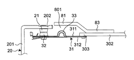
- FIG. 2 is a plan view for explaining a drive unit of the electromagnetic relay of FIG. 1;
- FIG. 7 is a perspective view showing a second modification of the electromagnetic relay of FIG. 1;
- the electromagnetic relay 1 includes a box-shaped insulating housing 10 and a first fixed contact side terminal 20 fixed to the housing 10 and a first movable contact side.
- a terminal 30, a second fixed contact side terminal 40, and a second movable contact side terminal 50 are provided.
- Each of the first fixed contact terminal 20, the first movable contact terminal 30, the second fixed contact terminal 40, and the second movable contact terminal 50 is a substantially L-shaped rectangular plate in which an intermediate portion in the longitudinal direction is bent. In the shape of a circle. Also, the second fixed contact side terminal 40 and the second movable contact side terminal 50 are disposed between the first fixed contact side terminal 20 and the first movable contact side terminal 30, and the first fixed contact side terminal 20 Ends of the housing 10 of the first movable contact side terminal 30, the second fixed contact side terminal 40, and the second movable contact side terminal 50 on the outer side are aligned substantially in a straight line.
- the housing 10 is, as shown in FIG. 1, formed of a substantially rectangular box-shaped base 11 and a substantially rectangular plate-shaped cover 12, and as shown in FIG. That is, the housing portion 13 is covered by the base 11 and the cover 12.
- the first fixed contact side terminal 20 is, as shown in FIG. 2, on the first side wall 111 of the first side wall 111 and the second side wall 112 opposed in the longitudinal direction of the base 11 (that is, the left and right direction in FIG. It is fixed and extends from the outside of the housing 10 to the housing portion 13.
- the first fixed contact side terminal 20 is a direction from the first side wall 111 of the base 11 along the short direction of the base 11 to the fourth side wall 114 from the outside of the housing 10 from the first side wall 111 (that is, 2 is connected to the end of the outer terminal 201 on the first side wall 111 side, and the inside of the housing 10 is arranged along the longitudinal direction of the base 11 from the first side wall 111 to the base 11 in the longitudinal direction.
- an inner terminal 202 extending toward the side wall 112.
- the first fixed contact portion 21 is fixed to the surface of the inner terminal 202 facing the fourth side wall 114.
- the first fixed contact portion 21 is disposed in the vicinity of the first side wall 111 of the base 11.
- the first movable contact side terminal 30 is fixed to the fourth side wall 114 side with respect to the first fixed contact side terminal 20 of the second side wall 112 of the base 11 as shown in FIG. It extends from the outside of the housing 10 to the housing 13 in an electrically independent manner.
- the first movable contact side terminal 30 extends outside the housing 10 from the second side wall 112 of the base 11 to the direction from the third side wall 113 to the fourth side wall 114 along the short direction of the base 11
- An internal portion of the housing 10 extending from the second side wall 112 of the base 11 to the first side wall 111 along the longitudinal direction of the base 11 is connected to the terminal 301 and the end of the outer terminal 301 on the second side wall 112 side.
- a first movable contact piece 31 is provided at an end portion 303 of the inner terminal 302 of the first movable contact-side terminal 30 on the first sidewall 111 side.
- the first movable contact piece 31 is disposed in the housing portion 13 and extends from the end portion 303 of the first movable contact side terminal 30 toward the first fixed contact side terminal 20.
- the first movable contact piece 31 is, for example, a plate-like laminate in which three elastically deformable rectangular plate members having conductivity are stacked in the plate thickness direction, and one end of the first movable contact piece 31 is The plate surface is fixed in contact with the plate surface of the end portion 303 of the inner terminal 302 of the first movable contact-side terminal 30.
- the first movable contact portion 32 is fixed to the surface of the other end of the first movable contact piece 31 opposite to the third side wall 113 of the base 11, and the fourth movable wall of the first movable contact piece 31 is fixed to the fourth side wall 114.
- the opposing surface is opposed to the inner terminal 502 and the second movable contact piece 51 of the second movable contact side terminal 50 described later. That is, the first movable contact piece 31 is disposed in the plate thickness direction (that is, the short direction of the base 11) and provided with the first movable contact portion 32; And a second surface 312 opposite to the first surface 311 in the plate thickness direction and facing the inner terminal 502 of the second movable contact piece 51 and the second movable contact side terminal 50.
- the first movable contact portion 32 is disposed to face the first fixed contact portion 21, and the first movable contact piece 31 is elastically deformed to shorten the base 11 with respect to the first fixed contact portion 21. It contacts or breaks along the hand direction.
- a U shape is formed toward the third side wall 113 of the base 11.
- the curved part 33 which protruded in shape is provided.
- the bending portion 33 can absorb and reduce the amount of bending of the first movable contact piece 31 when the first movable contact piece 31 is elastically deformed, and smooth operation characteristics can be ensured.
- the first movable contact side terminal 30 includes a first magnetic flux collecting piece 80 for collecting the magnetic flux from the first movable contact piece 31 and a magnetic flux from the inner terminal 302 of the first movable contact side terminal 30. And a first auxiliary magnetic flux collecting piece 83 for collecting
- the first magnetic flux collecting piece 80 is made of iron as an example, and as shown in FIG. 3, the first magnetic flux collecting piece 80 is disposed so as to have a gap 801 with the first movable contact piece 31. At least a part of the first surface 311 is covered.
- the first magnetic flux collection piece 80 intersects the plate-like horizontal plate portion 81 covering a part of the first surface 311 of the first movable contact piece 31, and the first surface 311 and the second surface 312 (for example, And two plate-like vertical plate portions 82 respectively covering portions of both side surfaces extending in the extending direction of the first movable contact piece 31 (that is, the short direction of the base 11).
- Each vertical plate portion 82 is connected to both ends in the width direction of the horizontal plate portion 81 (that is, in the left-right direction in FIG. 3) as shown in FIG. 3 and extends toward the fourth side wall 114 of the base 11 There is.
- the housing 10 is abbreviate
- the first auxiliary magnetic flux collection piece 83 has a plate shape made of iron as an example, and is connected to the end of the side wall portion 81 on the second side wall 112 side, as shown in FIG. A part of the surface of the inner terminal 302 of the movable contact-side terminal 30 facing the third side wall 113 is covered.
- the second fixed contact side terminal 40 is fixed to the fourth side wall 114 side of the first movable contact side terminal 30 of the second side wall 112 of the base 11 as shown in FIG. It extends from the outside of the housing 10 to the housing portion 13 in an electrically independent state with respect to the first movable contact terminal 30.
- the second fixed contact side terminal 40 extends outside the housing 10 from the second side wall 112 of the base 11 to the direction from the third side wall 113 to the fourth side wall 114 along the short direction of the base 11
- a terminal 401 is connected to an end of the outer terminal 401 on the second sidewall 112 side, and the inside of the housing 10 extends from the second sidewall 112 of the base 11 along the longitudinal direction of the base 11 toward the first sidewall 111
- the second fixed contact portion 41 is fixed to the surface of the inner terminal 402 facing the third side wall 113.
- the second fixed contact portion 41 is disposed in the vicinity of the second side wall 112 of the base 11.
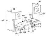
- the second movable contact side terminal 50 is fixed to an end of the fourth side wall 114 of the base 11 on the first side wall 111 side, and the first fixed contact side terminal 20, the first movable contact side terminal 30 and extends from the outside of the housing 10 to the housing portion 13 in an electrically independent state with respect to the second fixed contact terminal 40.
- the second movable contact side terminal 50 extends from the fourth side wall 114 of the base 11 to the outside of the housing 10 along the short direction of the base 11 and an outer terminal 501 extending away from the third side wall 113;
- An inner terminal 502 is connected to an end of the terminal 501 on the fourth side wall 112 side and extends inside the housing 10 from the fourth side wall 114 to the first side wall 111 to the second side wall 112 along the longitudinal direction of the base 11. And consists of.
- a second movable contact piece 51 is provided at an end portion 503 of the inner terminal 502 of the second movable contact-side terminal 50 on the second sidewall 111 side.
- the second movable contact piece 51 is disposed in the housing portion 13 adjacent to the first movable contact piece 31 in the thickness direction of the first movable contact piece 31 (that is, the short direction of the base 11). It extends from the end portion 503 of the side terminal 50 toward the second fixed contact side terminal 40.
- the second movable contact piece 51 is a plate-like laminate in which three elastically deformable rectangular plate members having conductivity are overlapped in the plate thickness direction, similarly to the first movable contact piece 31.
- the plate surface of one end portion in the longitudinal direction is fixed in contact with the plate surface of the end portion 503 of the inner terminal 502 of the second movable contact terminal 50.
- the second movable contact portion 52 is fixed to the surface of the other end of the second movable contact piece 51 opposite to the fourth side wall 114 of the base 11 and is fixed to the third side wall 113 of the second movable contact piece 51.
- the opposing surface is opposed to the inner terminal 302 and the first movable contact piece 31 of the first movable contact side terminal 30. That is, the second movable contact piece 51 is disposed in the plate thickness direction (that is, the short direction of the base 11) and faces the first movable contact piece 31 and the inner terminal 302 of the first movable contact side terminal 30.
- a third surface 511 and a fourth surface 512 which is disposed on the opposite side of the third surface 511 in the thickness direction of the second movable contact piece 51 and on which the second movable contact portion 52 is provided.
- the second movable contact portion 52 is disposed to face the second fixed contact portion 41, and the second movable contact piece 51 is elastically deformed to shorten the base 11 with respect to the second fixed contact portion 41. It contacts or breaks along the hand direction.
- a U shape is formed toward the fourth side wall 114 of the base 11.
- the curved part 53 which protruded in shape is provided.
- the curved portion 53 can absorb and reduce the amount of bending of the second movable contact piece 51 when the second movable contact piece 51 is elastically deformed, and can ensure smooth operation characteristics.
- the second movable contact side terminal 50 includes a second magnetic flux collecting piece 180 for collecting the magnetic flux from the second movable contact piece 51 and the inner terminal 502 of the second movable contact side terminal 50;
- a second auxiliary magnet-collecting piece 183 for collecting the magnetic flux from the inner terminal 502 of the second movable contact side terminal 50 is provided.
- the second magnetic flux collecting piece 180 is made of, for example, iron as the magnetic flux collecting piece 80, and is disposed so as to have a gap 802 (shown in FIGS. 4 and 5) with the second movable contact piece 51. And covers at least a part of the fourth surface 512 of the second movable contact piece 51.
- the second magnetic flux collection piece 180 has a configuration similar to that of the first magnetic flux collection piece 80. That is, as shown in FIG. 4 and FIG. 5, the second magnetic flux collection piece 180 has a plate-like horizontal plate portion 181 covering a part of the fourth surface 512 of the second movable contact piece 51, a third surface 511 and Two plate-like longitudinal plates which respectively intersect a part of the both sides intersecting (for example, orthogonally) the fourth surface 512 and extending in the extension direction of the second movable contact piece 51 (that is, the short direction of the base 11) And a portion 182. Each vertical plate portion 182 is connected to both end portions in the width direction of the horizontal plate portion 181 (that is, the X direction in FIG. 4), and extends toward the third side wall 113 of the base 11 as shown in FIG. There is.
- the second auxiliary magnetic flux collection piece 183 has a plate shape made of iron as an example, and is connected to the end portion of the side wall portion 81 on the first side wall 111 side, as shown in FIG. It covers a part of the surface of the inner terminal 502 of the movable contact-side terminal 50 facing the fourth side wall 114.
- the electromagnetic relay 1 includes the drive unit 2 including the electromagnet unit 60, the pivot block 70, the insulating first movable member 90, and the insulating second movable member 100. There is.
- the drive unit 2 is housed in the housing portion 13 of the housing 10.
- the electromagnet part 60 is arrange
- the electromagnet portion 60 is formed on the outer surface of the coil 61 from both axial ends of the coil 61 wound around the winding central axis CL extending in the longitudinal direction of the base 11 and the electromagnet portion 60 in which the winding central axis CL extends. It has a plate-like first yoke 62 and a plate-like second yoke 63 extending respectively along it.
- the first yoke 62 and the second yoke 63 are disposed between the first movable contact piece 31 and the second movable contact piece 51 and the electromagnet unit 60.
- the electromagnet unit 60 is provided with a coil terminal, and currents of two different directions can be selectively supplied to the electromagnet unit 60 through the coil terminal.
- the first yoke 62 extends from the third sidewall 113 to the fourth sidewall 114 along the first sidewall 111 of the base 11 from the end on the first sidewall 111 side in the axial direction of the electromagnet unit 60.
- a connection 621 extending in a direction (ie, downward in FIG. 6) and a first sidewall 111 from the first side wall 111 along the extension direction of the winding central axis CL from the tip of the connection 621 remote from the electromagnet 60.
- a suction portion 622 extends in a direction toward the side wall 112 (that is, rightward in FIG. 6).
- the second yoke 63 is directed from the third sidewall 113 to the fourth sidewall 114 along the second sidewall 112 of the base 11 from the end on the second sidewall 112 side in the axial direction of the electromagnet unit 60.
- a suction portion 632 extending in the left direction of FIG.
- the suction portion 622 of the first yoke 62 and the suction portion 632 of the second yoke 63 have an extension of the winding central axis CL in a plan view along the height direction of the base 11 (that is, the penetrating direction in FIG. 6).
- the center lines extending along the existing direction are arranged to coincide with each other. That is, the distal end surface of the suction portion 622 of the first yoke 62 and the distal end surface of the suction portion 632 of the second yoke 63 are opposed to each other, and a rotational block arrangement space in which the rotational block 70 can be disposed therebetween 64 are provided.
- protrusions 625 and 635 protruding in the height direction of the base 11 are provided on the suction portion 622 of the first yoke 62 and the suction portion 632 of the second yoke 63, respectively.
- the protrusions 625 and 635 can be fitted into through holes 661 and 662 of a fixing plate 66 described later.
- the pivot block 70 is, as shown in FIG. 6, a pivot block disposition space 64 of the housing portion 13 so as to be pivotable about a pivot axis 71 extending in the height direction of the base 11 relative to the base 11 of the housing 10 And rotate in different directions with respect to the base 11 of the housing 10 according to the direction of the current supplied to the electromagnet unit 60.
- the pivoting block 70 is disposed on the block housing 72 so as to face the block housing 72 (shown in FIG. 2), a permanent magnet 73 provided inside the block housing 72, and the permanent magnet 73. It has the plate-like 1st iron piece 74 and the plate-like 2nd iron piece 75 which were fixed.
- a first arm 721 extending toward the first side wall 111 of the base 11 is provided at an end on the fourth side wall 114 side and the first side wall 111 side of the block housing 72, and the fourth side wall of the block housing 72
- a second arm 722 extending toward the second side wall 112 of the base 11 is provided at the end on the 114 side and the second side wall 112 side.
- the first iron piece 74 has a first end 741 protruding from the permanent magnet 73 toward the first yoke 63 and a second end 742 protruding from the permanent magnet 73 toward the second yoke 63.
- the suction portion 622 of the first yoke 62 and the suction portion 632 of the second yoke 63 are disposed on the third side wall 113 side.
- the second iron piece 75 has a first end 751 protruding from the permanent magnet 73 toward the first yoke 63 and a second end 752 protruding from the permanent magnet 73 toward the second yoke 63.
- the suction portion 622 of the first yoke 62 and the suction portion 632 of the second yoke 63 are disposed on the fourth side wall 114 side.
- a first yoke 62 is disposed between the first ends 741 and 751 of the first iron piece 74 and the second iron piece 75, and the first end 741 or 751 of any one of the first iron piece 74 and the second iron piece 75. Is configured to contact the first yoke 62 in the turning direction of the turning block 70.
- the second yoke 63 is disposed between the second ends 742 and 752 of the first iron piece 74 and the second iron piece 75, and the second end 742 of one of the first iron piece 74 and the second iron piece 75. 752 are configured to contact the second yoke 63 in the rotation direction of the rotation block 70.
- the pivot block 70 is rotatably supported by the base 11 of the housing 10 and a fixing plate 66 fixed to the first yoke 62 and the second yoke 63 of the electromagnet unit 60.
- the fixing plate 66 has a substantially rectangular plate shape, and has through holes 661 and 662 penetrating in the thickness direction at both end portions in the longitudinal direction.
- the through holes 661 and 662 are respectively fitted to the projection 625 of the first yoke 62 and the projection 635 of the second yoke 63.
- an axial hole portion 663 into which the pivot shaft portion 76 of the block housing 72 constituting the pivot shaft 71 of the pivot block 70 can be inserted.
- the first movable member 90 is connected to the first movable contact piece 31 and the first arm portion 721 of the pivoting block 70, and in accordance with the pivoting direction of the pivoting block 70. It moves to elastically deform the first movable contact piece 31 to bring the first movable contact portion 32 into contact with or separate from the first fixed contact portion 21.
- the first movable member 90 is in the contact / separation direction in which the first movable contact portion 32 contacts or separates from the first fixed contact portion 21 when the pivoting block 70 rotates (ie, the short side of the base 11 Can be converted into linear motion in the direction (vertical direction in FIG. 2), and is connected to the end of the first arm 721 of the pivot block 70 while allowing the pivot block 70 to pivot.
- the second movable contact piece 31 is connected to the end on the first side wall 111 side (that is, the end on the left side in FIG. 2) in the extending direction of the first movable contact piece 31.
- the first movable member 90 is moved in the contact and separation direction by the rotation of the rotation block 70, and the end on the first side wall 111 side in the extension direction of the first movable contact piece 31 is the first movable contact portion It moves in the contact / separation direction in which 32 contacts or separates from the first fixed contact portion 21.
- the second movable member 100 is connected to the second movable contact piece 51 and the second arm 722 of the pivot block 70, and in accordance with the pivoting direction of the pivot block 70.
- the movable contact piece 51 is moved to elastically deform and the second movable contact portion 52 is brought into contact with or separated from the second fixed contact portion 41.
- the contact / separation direction in which the second movable contact portion 52 contacts or separates from the second fixed contact portion 41 when the second movable contact portion 52 rotates ie, the vertical direction in FIG. 2
- the second movable contact piece 51 It is connected to the end on the side of the second side wall 112 in the extending direction (that is, the end on the right side in FIG. 2).
- the second movable member 100 is moved in the contact and separation direction by the rotation of the rotation block 70, and the end on the second side wall 112 side in the extension direction of the second movable contact piece 51 is the second movable contact portion
- the second fixed contact portion 41 is moved in the contacting / separating direction in which it contacts or separates.
- the electromagnetic relay 1 returns from the operating state (that is, the first end 741 of the first iron piece 74 of the pivot block 70 contacts the suction portion 622 of the first yoke 62, The second end 752 of the second iron piece 75 contacts the suction portion 632 of the second yoke 63 to separate the first movable contact portion 32 from the first fixed contact portion 21 and the second movable contact portion 52 2)
- the fixed contact portion 41 is in the state of being separated and in contact with each other.
- the first movable contact piece 31 is disposed on one side (for example, the left side in FIG. 2) of the extending direction of the first movable contact piece 31 intersecting in the contact and separation direction.
- the first fixed contact terminal 20 or the first movable contact terminal 30 (here, the first fixed contact terminal 20) is a terminal to which current is supplied.
- the second fixed contact side terminal 40 or the second movable contact disposed on the other side (for example, the right side in FIG. 2) of the first movable contact piece 31 with respect to the second movable contact piece 51
- the side terminal 50 (here, the second fixed contact side terminal 40) is a terminal to which current is supplied.
- the second fixed portion is constituted by the first conductive portion 3 configured by the first fixed contact side terminal 20, the first movable contact side terminal 30, and the first movable contact piece 31 at the time of energization.
- Current flows in the opposite direction to each other through the second conductive portion 4 including the contact side terminal 40, the second movable contact side terminal 50, and the second movable contact piece 51 (in FIG. 2, the first conductive portion)
- the direction of the current flowing through 3 is shown by arrow C
- the direction of the current flowing through the second conductive portion 4 is shown by arrow D).
- the electromagnet block 60 of the electromagnetic relay 1 in the return state is supplied with a current in a direction different from the predetermined direction (for example, the B direction in FIG. 2) to make the pivot block 70 a pivot shaft 71 of the pivot block 70. It rotates counterclockwise as viewed from the extending direction. Then, with the rotation of the pivot block 70, the respective arm portions 721 and 722 also rotate counterclockwise to move the first movable member 90 toward the third side wall 113 of the base 11, and thereby the first movable contact The second movable member 52 is moved to the second fixed contact portion 41 by bringing the portion 32 into contact with the first fixed contact portion 21 and moving the second movable member 100 toward the fourth side wall 114 of the base 11. Contact to the other side.
- the predetermined direction for example, the B direction in FIG. 2
- the electromagnetic relay 1 includes the first movable contact piece 31 and the second movable contact piece 51, and the first movable contact piece 31 extends in the direction intersecting the plate thickness direction and is provided with the first movable contact portion 32.
- a first surface 311, and a second surface 312 which faces the first surface 311 in the thickness direction and which faces the second movable contact piece 51 and the inner terminal 502 of the second movable contact terminal 50;
- a third surface 511 of the second movable contact piece 51 extending in a direction intersecting the plate thickness direction and facing the inner terminals 302 of the first movable contact piece 31 and the first movable contact side terminal 30, and the plate thickness direction
- a fourth surface 512 facing the third surface 511 and provided with the second movable contact portion 52.
- the currents flowing through the first movable contact piece 31 and the second movable contact piece 51 flow in opposite directions. Therefore, when power is supplied, an electromagnetic repulsive force acts on the first movable contact piece 31 and the second movable contact piece 51 in the direction in which the movable contact portions 32, 52 approach the corresponding fixed contact portions 21, 41.
- the contact pressure of the movable contact portions 32, 52 to the corresponding fixed contact portions 21, 41 can be increased. As a result, the contact reliability of the movable contact portions 32 and 52 to the corresponding fixed contact portions 21 and 41 can be improved.
- the first movable contact piece 31 is disposed so as to have a gap between it and covers at least a part of the first surface 311 of the first movable contact piece 31 and collects magnetic flux from the first movable contact piece 31.
- a magnetic flux collecting piece 80 is provided. The magnetic flux spreading from the first movable contact piece 31 to the periphery thereof is collected by the first magnetic flux collection piece 80 and generated between the first movable contact piece 31 and the second movable contact piece 51 and the second movable contact side terminal 50
- the contact pressure of the first movable contact portion 32 to the first fixed contact portion 21 can be increased.
- the contact reliability of the first movable contact portion 32 to the first fixed contact portion 21 can be improved.
- the second movable contact piece 51 is disposed so as to have a gap with the second movable contact piece 51 and covers at least a part of the fourth surface 512 of the second movable contact piece 51.
- the second magnetic flux collecting piece 180 is provided to collect the magnetic flux from the The magnetic flux spreading from the second movable contact piece 51 to the periphery thereof is collected by the second magnetic flux collecting piece 180, and generated between the second movable contact piece 51 and the first movable contact piece 31 and the first movable contact side terminal 30.
- the first magnetic flux collection piece 80 is connected to the horizontal plate portion 81 covering at least a part of the first surface 311 of the first movable contact piece 31 and the horizontal plate portion 81, and the first surface 311 and the second surface 312 And a vertical plate portion 82 which covers at least a part of the side surface extending in the extending direction of the first movable contact piece 31 and which collects the magnetic flux from the first movable contact piece 31.
- the magnetic flux which spreads to the circumference from the 1st movable contact piece 31 can be collected more, and the contact pressure to the 1st fixed contact portion 21 of the 1st movable contact portion 32 can be raised certainly.
- the contact reliability of the first movable contact portion 32 to the first fixed contact portion 21 can be improved.
- the lateral plate portion 181 covering at least a part of the fourth surface 512 of the second movable contact piece 51 and the lateral plate portion 181 are connected and intersect the third surface 511 and the fourth surface 512
- a vertical plate portion 182 which covers at least a part of the side surface extending in the extending direction of the second movable contact piece 51 and collects the magnetic flux from the second movable contact piece 51. Therefore, it is possible to collect more magnetic flux spreading from the second movable contact piece 51 to the periphery thereof, and to reliably increase the contact pressure of the second movable contact portion 52 to the second fixed contact portion 41. As a result, the contact reliability of the second movable contact portion 52 to the second fixed contact portion 41 can be improved.
- a first auxiliary magnet-collecting piece 83 is further provided which covers at least a part of the first movable contact-side terminal 30 and collects the magnetic flux from the first movable contact-side terminal 30.
- the first auxiliary magnetic flux collecting piece 83 collects the magnetic flux spreading from the inner terminal 302 of the first movable contact side terminal 30 to the periphery, and the first movable contact side terminal 30, the second movable contact piece 51 and the second movable contact side
- the electromagnetic repulsive force generated between the terminal 50 and the terminal 50 can be increased to increase the contact pressure of the first movable contact portion 32 to the first fixed contact portion 21. As a result, the contact reliability of the first movable contact portion 32 to the first fixed contact portion 21 can be improved.
- the second auxiliary magnet-collecting piece 183 is further provided to cover at least a part of the second movable contact-side terminal 50 and to collect the magnetic flux from the second movable contact-side terminal 50.
- the second auxiliary magnetic flux collecting piece 183 collects the magnetic flux spreading from the inner terminal 502 of the second movable contact side terminal 50 to the periphery thereof, and the second movable contact side terminal 50, the first movable contact piece 31, and the first movable contact side
- the electromagnetic repulsive force generated between the terminal 30 and the contact 30 can be increased to increase the contact pressure of the second movable contact 52 with respect to the second fixed contact 41. As a result, the contact reliability of the second movable contact portion 52 to the second fixed contact portion 41 can be improved.
- the contact side terminal 50 and the circuit comprised with the 2nd movable contact piece 51 are provided, it does not restrict to this.
- the number of circuits may be plural, and three or more circuits may be provided.
- first movable contact piece 31 may be configured to face at least one of the second movable contact piece 51 and the inner terminal 502 of the second movable contact side terminal 50
- second movable contact The piece 51 may be configured to face at least one of the first movable contact piece 31 and the inner terminal 302 of the first movable contact terminal 30.
- the first movable magnetic contact piece 31 is provided with the first magnetic flux collecting piece 80
- the first movable contact side terminal 30 is provided with the first auxiliary magnetic flux collecting piece 83.
- the second magnetic flux collecting piece 180 is provided at 51 and the second auxiliary magnetic flux collecting piece 183 is provided at the second movable contact side terminal 50
- the present invention is not limited to this. Only one of the first magnetic flux collecting piece 80 and the first auxiliary magnetic flux collecting piece 83 or the second magnetic flux collecting piece 180 and the second auxiliary magnetic flux collecting piece 183 may be provided.
- a magnetic flux collecting piece and an auxiliary magnetic flux collecting piece may be provided on any of a plurality of sets of the movable contact piece and the movable contact side terminal provided, or all of the provided movable contact piece and the movable contact side terminal
- the magnetic flux collecting piece and the auxiliary magnetic flux collecting piece may be provided in the set of.
- only the first magnetic flux collecting piece 80 and / or the second magnetic flux collecting piece 180 may be provided, or only the first auxiliary magnetic flux collecting piece 83 and / or the second auxiliary magnetic flux collecting piece 183 may be provided.
- the housing 10 is provided with a holding portion for holding the first magnetic flux collecting piece 80 and / or the second magnetic flux collecting piece 180 Just do it.
- the first magnetic flux collecting piece 80 is not limited to the case where the horizontal plate portion 81 and the vertical plate portion 82 are provided.
- the horizontal plate portion 81 may be provided.
- the second magnetic flux collecting piece 180 may be configured to have only the horizontal plate portion 181 as well.
- the first magnetic flux collection piece 80 is an auxiliary horizontal plate covering at least a part of the second surface 312 of the first movable contact piece 31. It may have a portion 84.
- the auxiliary horizontal plate portion 84 is disposed to face the horizontal plate portion 81, and the vertical plate portions 82 are connected to both ends in the width direction (the X direction in FIG. 8). That is, in the first magnetic flux collecting piece 80, the extending direction of the first movable contact piece 31 (that is, the Y direction in FIG. 8) by the horizontal plate portion 81, the two vertical plate portions 82, and the auxiliary horizontal plate portion 84.
- the second magnetic flux collector 180 may be configured to have only the auxiliary horizontal plate.
- the first auxiliary magnetic flux collection piece 83 may be configured to surround the periphery of the first movable contact side terminal 30 in the extension direction of the inner terminal 302 of the first movable contact side terminal 30, or the second auxiliary The magnetic flux collecting piece 183 may surround the second movable contact terminal 50 in the extending direction of the second movable contact terminal 50.
- the magnetic flux spreading from the first movable contact side terminal 30 and / or the second movable contact side terminal 50 to the periphery is collected more, and the contact pressure to the first fixed contact portion 21 of the first movable contact portion 32 and / or Alternatively, the contact pressure of the second movable contact portion 52 to the second fixed contact portion 41 can be reliably increased.
- the first auxiliary magnetic flux collection piece 83 and the second auxiliary magnetic flux collection piece 183 may be provided to be in contact with the first movable contact side terminal 30 and the second movable contact side terminal 50, or may be provided with a gap. May be
- the electromagnetic relay 1 of the first aspect of the present disclosure is A box-shaped insulating housing 10 having a housing 13 therein; A plate-shaped first fixed contact side terminal 20 fixed to the housing 10 and extending from the outside of the housing 10 to the receiving portion 13 and having a first fixed contact portion 21 located in the receiving portion 13; A plate-shaped first movable member fixed to the housing 10 and extending from the outside of the housing 10 to the housing portion 13 and electrically independent of the first fixed contact terminal 20 A contact side terminal 30, The first movable contact side terminal 30 is disposed in the housing portion 13, extends from the first movable contact side terminal 30 toward the first fixed contact side terminal 20, and is electrically connected to the first movable contact side terminal 30.
- the first movable contact piece 31 of It is fixed to the housing 10, extends from the outside of the housing 10 to the accommodating portion 13, and is disposed so as to be electrically independent of the first fixed contact side terminal 20 and the first movable contact side terminal 30.
- a plate-like second fixed contact side terminal 40 having a second fixed contact portion 41 located in the housing portion 13;
- the first fixed contact side terminal 20, the first movable contact side terminal 30, and the second fixed contact side terminal are fixed to the housing 10 and extend from the outside of the housing 10 to the housing portion 13.
- the first movable contact piece 31 is disposed in the accommodation portion 13 adjacent to the first movable contact piece 31 in the thickness direction of the first movable contact piece 31, from the second movable contact side terminal 50 toward the second fixed contact side terminal 40 And has a second movable contact portion 52 which is electrically connected to the second movable contact side terminal 50 and which faces the second fixed contact portion 41, and the second movable contact portion 52 is the second movable contact portion 52.
- the second movable contact piece 51 extends in a direction intersecting the plate thickness direction and has a third surface 511 facing at least one of the first movable contact piece 31 and the first movable contact side terminal 30, and And a fourth surface 512 facing the third surface 511 and provided with the second movable contact portion 52,
- the first fixed contact-side terminal 20 or the first movable terminal disposed on one side in the extending direction of the first movable contact piece 31 intersecting the contact / separation direction with respect to the first movable contact piece 31
- the first movable contact piece 31 includes the first movable contact piece 31 and the second movable contact piece 51, and the first movable contact piece 31 extends in the direction intersecting the plate thickness direction and is the first movable contact A first surface 311 on which the portion 32 is provided, and a second surface 312 facing the first surface 311 and facing at least one of the second movable contact piece 51 and the second movable contact terminal 50; A third surface 511 of the second movable contact piece 51 extending in a direction intersecting the plate thickness direction and facing at least one of the first movable contact piece 31 and the first movable contact side terminal 30, and a third surface 511 And a fourth surface 512 on which the second movable contact portion 52 is provided.
- the directions of the currents flowing through the first movable contact piece 31 and the second movable contact piece 51 are different from each other. Therefore, when power is supplied, an electromagnetic repulsive force acts on the first movable contact piece 31 and the second movable contact piece 51 in the direction in which the movable contact portions 32, 52 approach the corresponding fixed contact portions 21, 41.
- the contact pressure of the movable contact portions 32, 52 to the corresponding fixed contact portions 21, 41 can be increased. As a result, the contact reliability of the movable contact portions 32 and 52 to the corresponding fixed contact portions 21 and 41 can be improved.
- the electromagnetic relay 1 of the second aspect of the present disclosure is
- the first movable contact piece 31 is disposed in the housing portion 13 and disposed so as to have a gap 801 with the first movable contact piece 31, and covers at least a part of the first surface 311 of the first movable contact piece 31;
- a magnetic flux collecting piece 80 for collecting the magnetic flux from the one movable contact piece 31 is further provided.
- the electromagnetic relay 1 of the second aspect magnetic flux spreading from the first movable contact piece 31 to its periphery is collected by the magnetic flux collecting piece 80, and the first movable contact piece 31, the second movable contact piece 51, and the second movable contact
- the electromagnetic repulsive force generated between the side terminal 50 can be increased, and the contact pressure of the first movable contact portion 32 to the first fixed contact portion 21 can be increased.
- the contact reliability of the first movable contact portion 32 to the first fixed contact portion 21 can be improved.
- the electromagnetic relay 1 of the third aspect of the present disclosure is
- the magnet collection piece 80 is A horizontal plate portion 81 covering at least a part of the first surface 311 of the first movable contact piece 31; Covers at least a part of a side surface connected to the horizontal plate portion 81, intersecting the first surface 311 and the second surface 321, and extending in the extending direction of the first movable contact piece 31; And a vertical plate portion 82 for collecting the magnetic flux from the piece 31.
- the electromagnetic relay 1 of the third aspect more magnetic flux spreading from the first movable contact piece 31 to the periphery is collected to surely increase the contact pressure of the first movable contact portion 32 to the first fixed contact portion 21. Can. As a result, the contact reliability of the first movable contact portion 32 to the first fixed contact portion 21 can be improved.
- the electromagnetic relay 1 of the fourth aspect of the present disclosure is
- the magnetic flux collecting piece 80 is connected to the vertical plate portion 82, covers at least a part of the second surface 312 of the first movable contact piece 31, and collects the magnetic flux from the first movable contact piece 31.
- a plate portion 84 is provided.
- the first movable contact piece 31 is surrounded by the horizontal plate portion 81, the vertical plate portion 82, and the auxiliary horizontal plate portion 84. As a result, it is possible to collect more magnetic flux spreading from the first movable contact piece 31 to the periphery thereof, and to reliably increase the contact pressure of the first movable contact portion 32 to the first fixed contact portion 21. As a result, the contact reliability of the first movable contact portion 32 to the first fixed contact portion 21 can be improved.
- the electromagnetic relay 1 of the fifth aspect of the present disclosure is It further includes an auxiliary magnetic flux collecting piece 83 covering at least a part of the first movable contact side terminal 30 and collecting the magnetic flux from the first movable contact side terminal 30.
- the magnetic flux spreading from the first movable contact side terminal 30 to the periphery is collected by the auxiliary magnetic flux collection piece 83, and the first movable contact side terminal 30, the second movable contact piece 51, and the The electromagnetic repulsive force generated between the second movable contact terminal 50 and the second movable contact terminal 50 can be increased, and the contact pressure of the first movable contact portion 32 to the first fixed contact portion 21 can be increased. As a result, the contact reliability of the first movable contact portion 32 with respect to the first fixed contact portion can be improved.
- the electromagnetic relay of the present disclosure can be applied to, for example, a smart meter.
Landscapes
- Physics & Mathematics (AREA)
- Electromagnetism (AREA)
- Contacts (AREA)
Applications Claiming Priority (2)
| Application Number | Priority Date | Filing Date | Title |
|---|---|---|---|
| JP2017-151945 | 2017-08-04 | ||
| JP2017151945A JP6922534B2 (ja) | 2017-08-04 | 2017-08-04 | 電磁継電器 |
Publications (1)
| Publication Number | Publication Date |
|---|---|
| WO2019026756A1 true WO2019026756A1 (ja) | 2019-02-07 |
Family
ID=65233510
Family Applications (1)
| Application Number | Title | Priority Date | Filing Date |
|---|---|---|---|
| PCT/JP2018/028085 Ceased WO2019026756A1 (ja) | 2017-08-04 | 2018-07-26 | 電磁継電器 |
Country Status (2)
| Country | Link |
|---|---|
| JP (1) | JP6922534B2 (enExample) |
| WO (1) | WO2019026756A1 (enExample) |
Cited By (2)
| Publication number | Priority date | Publication date | Assignee | Title |
|---|---|---|---|---|
| WO2021001471A1 (en) * | 2019-07-02 | 2021-01-07 | Johnson Electric Germany GmbH & Co. KG | Switching contact system for a switching system |
| JP2024166176A (ja) * | 2023-05-18 | 2024-11-28 | シァメン ホンファ エレクトリック パワー コントロールズ カンパニー リミテッド | リレー |
Families Citing this family (1)
| Publication number | Priority date | Publication date | Assignee | Title |
|---|---|---|---|---|
| ES3038659T3 (en) * | 2021-06-18 | 2025-10-14 | Xiamen Hongfa Electric Power Controls Co Ltd | Multi-phase electromagnetic relay |
Citations (5)
| Publication number | Priority date | Publication date | Assignee | Title |
|---|---|---|---|---|
| JP2006032131A (ja) * | 2004-07-16 | 2006-02-02 | Matsushita Electric Works Ltd | 接点機構およびそれを用いるパワーリレー |
| JP2012517093A (ja) * | 2009-02-04 | 2012-07-26 | クロディ エルエルシー | 電磁リレーアセンブリ |
| JP2013041815A (ja) * | 2011-07-18 | 2013-02-28 | Anden | 継電器 |
| JP2014505345A (ja) * | 2011-02-11 | 2014-02-27 | クロディ エルエルシー | X型駆動モータ搭載の双安定型電磁式リレー |
| JP2015018767A (ja) * | 2013-07-12 | 2015-01-29 | オムロン株式会社 | 接点機構部 |
-
2017
- 2017-08-04 JP JP2017151945A patent/JP6922534B2/ja active Active
-
2018
- 2018-07-26 WO PCT/JP2018/028085 patent/WO2019026756A1/ja not_active Ceased
Patent Citations (5)
| Publication number | Priority date | Publication date | Assignee | Title |
|---|---|---|---|---|
| JP2006032131A (ja) * | 2004-07-16 | 2006-02-02 | Matsushita Electric Works Ltd | 接点機構およびそれを用いるパワーリレー |
| JP2012517093A (ja) * | 2009-02-04 | 2012-07-26 | クロディ エルエルシー | 電磁リレーアセンブリ |
| JP2014505345A (ja) * | 2011-02-11 | 2014-02-27 | クロディ エルエルシー | X型駆動モータ搭載の双安定型電磁式リレー |
| JP2013041815A (ja) * | 2011-07-18 | 2013-02-28 | Anden | 継電器 |
| JP2015018767A (ja) * | 2013-07-12 | 2015-01-29 | オムロン株式会社 | 接点機構部 |
Cited By (5)
| Publication number | Priority date | Publication date | Assignee | Title |
|---|---|---|---|---|
| WO2021001471A1 (en) * | 2019-07-02 | 2021-01-07 | Johnson Electric Germany GmbH & Co. KG | Switching contact system for a switching system |
| CN113841214A (zh) * | 2019-07-02 | 2021-12-24 | 广东德昌电机有限公司 | 开关系统的开关触点系统 |
| CN113841214B (zh) * | 2019-07-02 | 2023-12-12 | 广东德昌电机有限公司 | 开关系统的开关触点系统 |
| JP2024166176A (ja) * | 2023-05-18 | 2024-11-28 | シァメン ホンファ エレクトリック パワー コントロールズ カンパニー リミテッド | リレー |
| JP7703741B2 (ja) | 2023-05-18 | 2025-07-07 | シァメン ホンファ エレクトリック パワー コントロールズ カンパニー リミテッド | リレー |
Also Published As
| Publication number | Publication date |
|---|---|
| JP2019032947A (ja) | 2019-02-28 |
| JP6922534B2 (ja) | 2021-08-18 |
Similar Documents
| Publication | Publication Date | Title |
|---|---|---|
| CN102891039B (zh) | 继电器 | |
| CN102891040B (zh) | 继电器 | |
| US9305718B2 (en) | Electromagnetic relay | |
| US20110272258A1 (en) | Switching devices configured to control magnetic fields to maintain an electrical connection | |
| TWI524369B (zh) | 電磁繼電器 | |
| US10580603B2 (en) | Power switchgear | |
| JP2019032945A (ja) | 電磁継電器 | |
| WO2019026756A1 (ja) | 電磁継電器 | |
| WO2019026944A1 (ja) | 電磁継電器およびスマートメータ | |
| CN111295729B (zh) | 电磁继电器和电磁装置 | |
| JP6897408B2 (ja) | 電磁継電器 | |
| JP6011267B2 (ja) | 電磁継電器 | |
| JP6376231B1 (ja) | 電磁継電器およびスマートメータ | |
| JP6897409B2 (ja) | 電磁継電器 | |
| CN109427508B (zh) | 电磁继电器 | |
| JP5930094B1 (ja) | 電磁継電器 | |
| JP2019197608A (ja) | 電磁継電器 | |
| US10304647B2 (en) | Relay | |
| JP5930095B1 (ja) | 電磁駆動機構およびこれを備えた電磁継電器 | |
| JP2020123553A (ja) | 回路遮断器 |
Legal Events
| Date | Code | Title | Description |
|---|---|---|---|
| 121 | Ep: the epo has been informed by wipo that ep was designated in this application |
Ref document number: 18840467 Country of ref document: EP Kind code of ref document: A1 |
|
| NENP | Non-entry into the national phase |
Ref country code: DE |
|
| 122 | Ep: pct application non-entry in european phase |
Ref document number: 18840467 Country of ref document: EP Kind code of ref document: A1 |