WO2019026691A1 - 超音波内視鏡 - Google Patents
超音波内視鏡 Download PDFInfo
- Publication number
- WO2019026691A1 WO2019026691A1 PCT/JP2018/027704 JP2018027704W WO2019026691A1 WO 2019026691 A1 WO2019026691 A1 WO 2019026691A1 JP 2018027704 W JP2018027704 W JP 2018027704W WO 2019026691 A1 WO2019026691 A1 WO 2019026691A1
- Authority
- WO
- WIPO (PCT)
- Prior art keywords
- electrically connected
- ultrasonic
- board
- piezoelectric elements
- wiring pads
- Prior art date
- Legal status (The legal status is an assumption and is not a legal conclusion. Google has not performed a legal analysis and makes no representation as to the accuracy of the status listed.)
- Ceased
Links
Images

Classifications
-
- A—HUMAN NECESSITIES
- A61—MEDICAL OR VETERINARY SCIENCE; HYGIENE
- A61B—DIAGNOSIS; SURGERY; IDENTIFICATION
- A61B8/00—Diagnosis using ultrasonic, sonic or infrasonic waves
- A61B8/12—Diagnosis using ultrasonic, sonic or infrasonic waves in body cavities or body tracts, e.g. by using catheters
Definitions
- the present invention relates to an ultrasound endoscope.
- Ultrasound may be applied to observe the characteristics of the biological tissue or material to be observed.
- the ultrasonic observation apparatus can obtain information on the characteristics of the observation target by performing predetermined signal processing on ultrasonic echoes received from ultrasonic transducers that transmit and receive ultrasonic waves. .
- the ultrasonic transducer converts an electrical pulse signal into an ultrasonic pulse (acoustic pulse) and irradiates the observation target, and converts an ultrasonic echo reflected by the observation target into an electrical echo signal and outputs And a plurality of piezoelectric elements.
- ultrasonic echoes are acquired from the observation target by arranging a plurality of piezoelectric elements along a predetermined direction and electronically switching elements involved in transmission and reception.
- a substrate for electrically connecting the piezoelectric element and the flexible substrate is provided perpendicularly to the arrangement direction of the plurality of piezoelectric elements. Since this substrate is rigid, there is a problem that the miniaturization of the tip portion of the ultrasonic endoscope is hindered by this substrate.
- the present invention has been made in view of the above, and it is an object of the present invention to provide an ultrasonic endoscope having a compact tip.
- an ultrasonic endoscope includes a plurality of piezoelectric elements arranged in a curved surface with their longitudinal directions aligned, and the piezoelectric element A plurality of conducting wires whose one end is electrically connected to one end, a plurality of first wiring pads whose other ends are electrically connected, and the first wiring pad, respectively.
- a board having a plurality of second wiring pads electrically connected a flexible substrate having a plurality of wirings electrically connected to the plurality of second wiring pads, and a plurality of wirings And a plurality of coaxial cables electrically connected to each other.
- the board has the plurality of first wiring pads disposed on one surface, and the other surface has the plurality of second wiring pads. Are arranged.
- the ultrasonic endoscope according to one aspect of the present invention is characterized in that the plurality of piezoelectric elements are disposed between the two boards disposed to face each other.
- the flexible substrate has a shape connected to one sheet, and the plurality of second wiring pads respectively located on the outside of the two boards. Are electrically connected to each other.
- the plurality of piezoelectric elements, the plurality of conductive wires, and the board are accommodated in a housing in which a space is formed inside,
- the coaxial cable is electrically connected to the flexible substrate at the outside of the housing.
- the plurality of piezoelectric elements, the plurality of conductive wires, and the board are accommodated in a housing in which a space is formed inside,
- the coaxial cable is electrically connected to the flexible substrate inside the housing.
- a resin is filled between the housing and the board.
- an acoustic lens is formed on the opposite side of the surface of the plurality of piezoelectric elements to which the conducting wire is connected, and the acoustic lens It is characterized in that it is made of the same material as the resin.
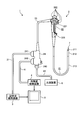
- FIG. 1 is a view schematically showing an endoscope system provided with an ultrasonic endoscope according to a first embodiment of the present invention.
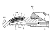
- FIG. 2 is a partial cross-sectional view of the distal end of the ultrasonic endoscope shown in FIG.
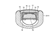
- FIG. 3 is a cross-sectional view corresponding to the line AA of FIG.
- FIG. 4 is an enlarged view of the board shown in FIG.
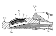
- FIG. 5 is a partial cross-sectional view of the distal end portion of the ultrasonic endoscope according to the second embodiment of the present invention.
- an embodiment of an ultrasound endoscope according to the present invention will be described with reference to the drawings. Note that the present invention is not limited by these embodiments.
- the present invention can be applied to ultrasound endoscopes in general provided with a convex-type ultrasound transducer.
- FIG. 1 is a view schematically showing an endoscope system provided with an ultrasonic endoscope according to a first embodiment of the present invention.
- the endoscope system 1 includes an ultrasonic endoscope 2, an ultrasonic observation device 3, an endoscopic observation device 4, a display device 5, and a light source device 6. .
- the ultrasonic endoscope 2 converts an electrical pulse signal received from the ultrasonic observation device 3 into an ultrasonic pulse (acoustic pulse) by an ultrasonic transducer, which will be described later, provided at the tip end of the ultrasonic endoscope 2 to be an object And converts the ultrasonic echo reflected by the object into an electrical echo signal represented by a voltage change and outputs it.
- the ultrasound endoscope 2 usually has an imaging optical system and an imaging element, and is inserted into the digestive tract (esophagus, stomach, duodenum, large intestine) or respiratory organ (trachea, bronchi) of a subject and digested It is possible to perform imaging of the tube and the respiratory system. Moreover, it is possible to image the surrounding organs (pancreas, gallbladder, bile duct, biliary tract, lymph nodes, mediastinal organs, blood vessels, etc.) using ultrasound.
- the ultrasound endoscope 2 has a light guide for guiding illumination light to be irradiated to the subject at the time of optical imaging.
- the light guide has a distal end portion reaching the distal end of the insertion portion of the ultrasonic endoscope 2 into the subject, while the proximal end portion is connected to the light source device 6 that generates illumination light.
- the ultrasound endoscope 2 includes an insertion unit 21, an operation unit 22, a universal cord 23, and a connector 24.
- the insertion unit 21 is a portion to be inserted into the subject.
- the insertion portion 21 is provided on the distal end side, and has a rigid distal end portion 211 for holding the ultrasonic transducer 7, a bending portion 212 connected to the base end side of the distal end portion 211 and being bendable, And a flexible tube portion 213 connected to the proximal end side and having flexibility.
- a light guide for transmitting illumination light supplied from the light source device 6 and a plurality of signal cables for transmitting various signals are drawn inside the insertion portion 21.
- a treatment instrument insertion path or the like for inserting the treatment instrument is formed.
- the ultrasonic transducer 7 is a convex-type ultrasonic transducer. Specifically, the ultrasonic endoscope 2 provides a plurality of piezoelectric elements as an array of ultrasonic transducers 7 in an array, electronically switches the piezoelectric elements involved in transmission and reception, and delays transmission and reception of each piezoelectric element It is a convex-type ultrasonic transducer that can be scanned electronically by The configuration of the ultrasonic transducer 7 will be described later.
- the operation unit 22 is connected to the proximal end side of the insertion unit 21 and is a portion that receives various operations from a doctor or the like. As shown in FIG. 1, the operation unit 22 includes a bending knob 221 for bending the bending portion 212 and a plurality of operation members 222 for performing various operations. Further, a treatment tool insertion port 223 is formed in the operation portion 22 so as to communicate with the treatment tool insertion path and for inserting the treatment tool in the treatment tool insertion path.
- the universal cord 23 is a cable which extends from the operation unit 22 and is provided with a plurality of signal cables for transmitting various signals, and an optical fiber for transmitting illumination light supplied from the light source device 6.
- the connector 24 is provided at the tip of the universal cord 23.
- the connector 24 has first to third connector portions 241 to 243 to which the ultrasonic cable 31, the video cable 41, and the optical fiber cable 61 are respectively connected.
- the ultrasound observation apparatus 3 is electrically connected to the ultrasound endoscope 2 via the ultrasound cable 31, and outputs a pulse signal to the ultrasound endoscope 2 via the ultrasound cable 31.
- An echo signal is input from the sound wave endoscope 2. Then, the ultrasonic observation device 3 performs predetermined processing on the echo signal to generate an ultrasonic image.
- the endoscope observation apparatus 4 is electrically connected to the ultrasound endoscope 2 via the video cable 41, and receives an image signal from the ultrasound endoscope 2 via the video cable 41. Then, the endoscope observation device 4 performs a predetermined process on the image signal to generate an endoscope image.
- the display device 5 is configured using a liquid crystal or organic EL (Electro Luminescence), a projector, a CRT (Cathode Ray Tube), or the like, and an ultrasound image generated by the ultrasound observation device 3 or the endoscope observation device 4 The endoscopic image etc. which were produced
- a liquid crystal or organic EL Electro Luminescence
- a projector a projector
- a CRT Cathode Ray Tube
- the light source device 6 is connected to the ultrasonic endoscope 2 via the optical fiber cable 61 and supplies illumination light for illuminating the inside of the subject via the optical fiber cable 61 to the ultrasonic endoscope 2.
- FIG. 2 is a partial cross-sectional view of the distal end of the ultrasonic endoscope shown in FIG.
- FIG. 3 is a cross-sectional view corresponding to the line AA of FIG.
- the ultrasonic transducer 7 is a convex-type ultrasonic vibration having a plurality of piezoelectric elements 71 arranged in a curved surface with their longitudinal directions (directions perpendicular to the sheet of FIG. 2) aligned. It is a child.
- the ultrasonic transducer 7 has a prismatic shape, and one end of one of the piezoelectric element 71 and the piezoelectric element 71 whose longitudinal direction is disposed orthogonal to the extending direction of the insertion portion 21 is electrically And the boards 73 (see FIG. 3) to which the other ends of the leads 72 are electrically connected, and the flexible lines electrically connected to the board 73.
- a substrate 74 and a plurality of coaxial cables 75 (see FIG. 2) electrically connected to the flexible substrate 74 are provided.
- the distal end (the plurality of piezoelectric elements 71, the plurality of conducting wires 72, and the board 73) of the ultrasonic transducer 7 is accommodated in a housing 2111 in which a space is formed.
- an acoustic lens 76 is formed on the opposite side of the surface of the plurality of piezoelectric elements 71 to which the conducting wire 72 is connected.
- resin 77 is filled between the housing 2111 and the board 73.
- the inside of the board 73 is filled with a resin 78.
- the housing 2111 is made of a hard material such as resin, and a space for housing the tip of the ultrasonic transducer 7 is formed inside.
- the piezoelectric element 71 is disposed between two boards 73 disposed to face each other.
- the piezoelectric element 71 converts an electrical pulse signal into an ultrasonic pulse (acoustic pulse) and irradiates the subject with an electrical echo signal that expresses an ultrasound echo reflected by the subject by a voltage change. Convert and output.
- an acoustic matching layer for matching the acoustic impedance of the piezoelectric element 71 with the observation target is provided. It may be provided.
- the conducting wire 72 is a conductor made of metal or alloy, and one end thereof is electrically connected to the piezoelectric element 71 by soldering or the like, and the other end is soldered to a first wiring pad of the board 73 described later. Are electrically connected.
- FIG. 4 is an enlarged view of the board shown in FIG.
- the two boards 73 disposed on both sides of the piezoelectric element 71 have sides having the same curvature as the curved surface formed by arranging the plurality of piezoelectric elements 71 (upper side in FIG.
- a plate-like member having a side of (B) of FIG. 4 is a view of (a) of FIG. 4 as viewed from the side (the left side of (a) of FIG. 4).
- the board 73 includes a hard plate-like substrate 731, a plurality of first wiring pads 732 formed on one surface of the substrate 731, and the other of the substrate 731. And a plurality of second wiring pads 733 formed on the surface.
- the substrate 731 is made of hard resin or the like and is disposed on both sides of the piezoelectric element 71. Furthermore, two boards are disposed at the end of the front end side and the rear end side of the piezoelectric element 71 (ends on the right side and the left side in FIG. 2), and a box-like space is formed by these four boards. Is formed. The resin 78 is filled in this space.
- the two boards 73 are arranged with the first wiring pads 732 facing each other.
- the first wiring pad 732 is electrically connected to one end of the conducting wire 72 (the end opposite to the end electrically connected to the piezoelectric element 71).
- the first wiring pad 732 and the second wiring pad 733 are electrically connected to each other by a conductor disposed through the substrate 731.
- the flexible substrate 74 has a plurality of wires electrically connected to the plurality of second wiring pads 733, respectively.
- the flexible substrate 74 has a shape of being connected to one sheet, and is electrically connected to a plurality of second wiring pads 733 respectively positioned on the outside of the two boards 73 disposed opposite to each other.
- the flexible substrate 74 is made of a flexible material, and is accommodated inside the housing 2111 in a curved or bent state.
- FIG. 3 shows a configuration in which the flexible substrate 74 is arranged in a state of being curved in an arc shape.
- the flexible substrate 74 may be disposed so as to be bent in a bellows shape, or may be disposed in a rectangular shape along the board 73.
- the flexible substrates 74 may be connected to, for example, two boards 73 one by one.
- the flexible substrate 74 may be divided into a plurality of pieces in the arrangement direction of the piezoelectric elements 71.
- the coaxial cable 75 is electrically connected to the flexible substrate 74 outside the housing 2111.
- the acoustic lens 76 is formed using silicone, polymethyl pentene, epoxy resin, polyether imide, or the like, and has a function of squeezing an ultrasonic wave by forming a convex or concave shape on one side.
- the acoustic lens 76 emits the ultrasonic wave emitted from the piezoelectric element 71 to the outside, or takes in an ultrasonic echo from the outside.
- the acoustic lens 76 can be optionally provided, and the acoustic lens 76 may not be provided.
- the resin 77 is made of, for example, the same material as that of the acoustic lens 76, but may be made of a material different from that of the acoustic lens 76.
- the resin 78 functions as a backing material that attenuates unnecessary ultrasonic vibrations generated by the operation of the piezoelectric element 71.
- the resin 78 is formed using a material having a large damping rate, for example, an epoxy resin in which a filler such as alumina or zirconia is dispersed, or a rubber in which the filler described above is dispersed.
- the ultrasonic transducer 7 having the above configuration vibrates the piezoelectric element 71 by the input of the pulse signal, and propagates through the acoustic lens 76 to irradiate the ultrasonic wave to the observation target.
- the unnecessary vibration from the piezoelectric element 71 is attenuated by the resin 78.
- the ultrasonic wave reflected from the observation target propagates through the acoustic lens 76 and is transmitted to the piezoelectric element 71.
- the piezoelectric element 71 vibrates by the transmitted ultrasonic wave, and the piezoelectric element 71 converts the vibration into an electrical echo signal, and as the echo signal, the conducting wire 72, the first wiring pad 732, the second wiring pad 733, The signal is output to the ultrasonic observation apparatus 3 via the flexible substrate 74 and the coaxial cable 75.
- the flexible substrate 74 having flexibility is connected to the outside of the board 73 accommodating the resin 78.
- the flexible substrate 74 and the coaxial cable 75 are connected outside the housing 2111, the flexible substrate and the coaxial cable are connected inside the housing. It is possible to realize an ultrasonic endoscope having a smaller tip portion than the configuration.
- FIG. 5 is a partial cross-sectional view of the distal end portion of the ultrasonic endoscope according to the second embodiment of the present invention.
- the flexible substrate 74A of the ultrasonic transducer 7A and the coaxial cable 75A are electrically connected in the inside of the housing 2111. It is done.
- the flexible substrate 74A and the coaxial cable 75A may be connected in the housing 2111.
- the flexible substrate 74A having flexibility is connected to the outside of the board 73 accommodating the resin 78. As a result, it is not necessary to provide a substrate orthogonal to the arrangement direction of the plurality of piezoelectric elements 71, and an ultrasonic endoscope with a small tip can be realized.
- the first wiring pad is disposed on one side of the board and the second wiring pad is disposed on the other side of the board. I can not.
- the first wiring pad may be disposed on one side of the board, and the second wiring pad may be disposed on the side of the board (for example, the lower side of FIG. 3).
Landscapes
- Life Sciences & Earth Sciences (AREA)
- Health & Medical Sciences (AREA)
- Biomedical Technology (AREA)
- Biophysics (AREA)
- Nuclear Medicine, Radiotherapy & Molecular Imaging (AREA)
- Pathology (AREA)
- Radiology & Medical Imaging (AREA)
- Engineering & Computer Science (AREA)
- Physics & Mathematics (AREA)
- Heart & Thoracic Surgery (AREA)
- Medical Informatics (AREA)
- Molecular Biology (AREA)
- Surgery (AREA)
- Animal Behavior & Ethology (AREA)
- General Health & Medical Sciences (AREA)
- Public Health (AREA)
- Veterinary Medicine (AREA)
- Ultra Sonic Daignosis Equipment (AREA)
Applications Claiming Priority (2)
| Application Number | Priority Date | Filing Date | Title |
|---|---|---|---|
| JP2017-150882 | 2017-08-03 | ||
| JP2017150882A JP6952533B2 (ja) | 2017-08-03 | 2017-08-03 | 超音波内視鏡 |
Publications (1)
| Publication Number | Publication Date |
|---|---|
| WO2019026691A1 true WO2019026691A1 (ja) | 2019-02-07 |
Family
ID=65232580
Family Applications (1)
| Application Number | Title | Priority Date | Filing Date |
|---|---|---|---|
| PCT/JP2018/027704 Ceased WO2019026691A1 (ja) | 2017-08-03 | 2018-07-24 | 超音波内視鏡 |
Country Status (2)
| Country | Link |
|---|---|
| JP (1) | JP6952533B2 (enExample) |
| WO (1) | WO2019026691A1 (enExample) |
Citations (2)
| Publication number | Priority date | Publication date | Assignee | Title |
|---|---|---|---|---|
| WO2014006954A1 (ja) * | 2012-07-04 | 2014-01-09 | オリンパスメディカルシステムズ株式会社 | 超音波内視鏡 |
| WO2014034191A1 (ja) * | 2012-08-27 | 2014-03-06 | オリンパスメディカルシステムズ株式会社 | 超音波内視鏡 |
-
2017
- 2017-08-03 JP JP2017150882A patent/JP6952533B2/ja active Active
-
2018
- 2018-07-24 WO PCT/JP2018/027704 patent/WO2019026691A1/ja not_active Ceased
Patent Citations (2)
| Publication number | Priority date | Publication date | Assignee | Title |
|---|---|---|---|---|
| WO2014006954A1 (ja) * | 2012-07-04 | 2014-01-09 | オリンパスメディカルシステムズ株式会社 | 超音波内視鏡 |
| WO2014034191A1 (ja) * | 2012-08-27 | 2014-03-06 | オリンパスメディカルシステムズ株式会社 | 超音波内視鏡 |
Also Published As
| Publication number | Publication date |
|---|---|
| JP6952533B2 (ja) | 2021-10-20 |
| JP2019025241A (ja) | 2019-02-21 |
Similar Documents
| Publication | Publication Date | Title |
|---|---|---|
| JP6741637B2 (ja) | 超音波内視鏡 | |
| WO2018003322A1 (ja) | 超音波内視鏡 | |
| CN107708573B (zh) | 超声波内窥镜 | |
| US11872081B2 (en) | Ultrasound transducer, ultrasound endoscope, and manufacturing method of ultrasound transducer | |
| US11160530B2 (en) | Ultrasonic transducer module, ultrasonic endoscope and processing method of ultrasonic transducer module | |
| JP6133001B1 (ja) | 超音波振動子モジュールおよび超音波内視鏡 | |
| JP6952533B2 (ja) | 超音波内視鏡 | |
| JP2023129671A (ja) | 超音波内視鏡 | |
| JP6697962B2 (ja) | 超音波振動子および超音波内視鏡 | |
| US11944496B2 (en) | Ultrasound endoscope | |
| JP2017074231A (ja) | 超音波内視鏡の製造方法および超音波内視鏡 | |
| JP7395277B2 (ja) | 信号伝送配線接続ユニット、内視鏡、信号伝送配線接続ユニットの製造方法および超音波振動子モジュール | |
| US20230052510A1 (en) | Multilayer board, probe unit, and ultrasound endoscope | |
| CN109475347B (zh) | 超声波振子组件及超声波内窥镜 | |
| WO2022074776A1 (ja) | 信号伝送配線接続ユニット、内視鏡、信号伝送配線接続ユニットの製造方法および超音波振動子モジュール | |
| JP2023129670A (ja) | 超音波内視鏡 |
Legal Events
| Date | Code | Title | Description |
|---|---|---|---|
| 121 | Ep: the epo has been informed by wipo that ep was designated in this application |
Ref document number: 18840750 Country of ref document: EP Kind code of ref document: A1 |
|
| NENP | Non-entry into the national phase |
Ref country code: DE |
|
| 122 | Ep: pct application non-entry in european phase |
Ref document number: 18840750 Country of ref document: EP Kind code of ref document: A1 |