WO2014034191A1 - 超音波内視鏡 - Google Patents
超音波内視鏡 Download PDFInfo
- Publication number
- WO2014034191A1 WO2014034191A1 PCT/JP2013/063807 JP2013063807W WO2014034191A1 WO 2014034191 A1 WO2014034191 A1 WO 2014034191A1 JP 2013063807 W JP2013063807 W JP 2013063807W WO 2014034191 A1 WO2014034191 A1 WO 2014034191A1
- Authority
- WO
- WIPO (PCT)
- Prior art keywords
- circuit board
- ultrasonic
- rigid
- wiring
- electrically connected
- Prior art date
Links
Images


Classifications
-
- A—HUMAN NECESSITIES
- A61—MEDICAL OR VETERINARY SCIENCE; HYGIENE
- A61B—DIAGNOSIS; SURGERY; IDENTIFICATION
- A61B8/00—Diagnosis using ultrasonic, sonic or infrasonic waves
- A61B8/12—Diagnosis using ultrasonic, sonic or infrasonic waves in body cavities or body tracts, e.g. by using catheters
-
- A—HUMAN NECESSITIES
- A61—MEDICAL OR VETERINARY SCIENCE; HYGIENE
- A61B—DIAGNOSIS; SURGERY; IDENTIFICATION
- A61B1/00—Instruments for performing medical examinations of the interior of cavities or tubes of the body by visual or photographical inspection, e.g. endoscopes; Illuminating arrangements therefor
-
- A—HUMAN NECESSITIES
- A61—MEDICAL OR VETERINARY SCIENCE; HYGIENE
- A61B—DIAGNOSIS; SURGERY; IDENTIFICATION
- A61B8/00—Diagnosis using ultrasonic, sonic or infrasonic waves
- A61B8/44—Constructional features of the ultrasonic, sonic or infrasonic diagnostic device
- A61B8/4444—Constructional features of the ultrasonic, sonic or infrasonic diagnostic device related to the probe
- A61B8/445—Details of catheter construction
-
- A—HUMAN NECESSITIES
- A61—MEDICAL OR VETERINARY SCIENCE; HYGIENE
- A61B—DIAGNOSIS; SURGERY; IDENTIFICATION
- A61B8/00—Diagnosis using ultrasonic, sonic or infrasonic waves
- A61B8/44—Constructional features of the ultrasonic, sonic or infrasonic diagnostic device
- A61B8/4483—Constructional features of the ultrasonic, sonic or infrasonic diagnostic device characterised by features of the ultrasound transducer
- A61B8/4494—Constructional features of the ultrasonic, sonic or infrasonic diagnostic device characterised by features of the ultrasound transducer characterised by the arrangement of the transducer elements
-
- A—HUMAN NECESSITIES
- A61—MEDICAL OR VETERINARY SCIENCE; HYGIENE
- A61B—DIAGNOSIS; SURGERY; IDENTIFICATION
- A61B8/00—Diagnosis using ultrasonic, sonic or infrasonic waves
- A61B8/56—Details of data transmission or power supply
-
- H—ELECTRICITY
- H01—ELECTRIC ELEMENTS
- H01R—ELECTRICALLY-CONDUCTIVE CONNECTIONS; STRUCTURAL ASSOCIATIONS OF A PLURALITY OF MUTUALLY-INSULATED ELECTRICAL CONNECTING ELEMENTS; COUPLING DEVICES; CURRENT COLLECTORS
- H01R12/00—Structural associations of a plurality of mutually-insulated electrical connecting elements, specially adapted for printed circuits, e.g. printed circuit boards [PCB], flat or ribbon cables, or like generally planar structures, e.g. terminal strips, terminal blocks; Coupling devices specially adapted for printed circuits, flat or ribbon cables, or like generally planar structures; Terminals specially adapted for contact with, or insertion into, printed circuits, flat or ribbon cables, or like generally planar structures
- H01R12/50—Fixed connections
- H01R12/59—Fixed connections for flexible printed circuits, flat or ribbon cables or like structures
- H01R12/62—Fixed connections for flexible printed circuits, flat or ribbon cables or like structures connecting to rigid printed circuits or like structures
-
- H—ELECTRICITY
- H01—ELECTRIC ELEMENTS
- H01R—ELECTRICALLY-CONDUCTIVE CONNECTIONS; STRUCTURAL ASSOCIATIONS OF A PLURALITY OF MUTUALLY-INSULATED ELECTRICAL CONNECTING ELEMENTS; COUPLING DEVICES; CURRENT COLLECTORS
- H01R12/00—Structural associations of a plurality of mutually-insulated electrical connecting elements, specially adapted for printed circuits, e.g. printed circuit boards [PCB], flat or ribbon cables, or like generally planar structures, e.g. terminal strips, terminal blocks; Coupling devices specially adapted for printed circuits, flat or ribbon cables, or like generally planar structures; Terminals specially adapted for contact with, or insertion into, printed circuits, flat or ribbon cables, or like generally planar structures
- H01R12/50—Fixed connections
- H01R12/59—Fixed connections for flexible printed circuits, flat or ribbon cables or like structures
- H01R12/63—Fixed connections for flexible printed circuits, flat or ribbon cables or like structures connecting to another shape cable
-
- H—ELECTRICITY
- H01—ELECTRIC ELEMENTS
- H01R—ELECTRICALLY-CONDUCTIVE CONNECTIONS; STRUCTURAL ASSOCIATIONS OF A PLURALITY OF MUTUALLY-INSULATED ELECTRICAL CONNECTING ELEMENTS; COUPLING DEVICES; CURRENT COLLECTORS
- H01R2201/00—Connectors or connections adapted for particular applications
- H01R2201/12—Connectors or connections adapted for particular applications for medicine and surgery
Definitions
- the present invention relates to an ultrasonic endoscope in which a transducer unit is accommodated in a housing provided at a distal end portion of an insertion portion.
- an ultrasonic endoscope provided with an ultrasonic probe at the tip of an elongated endoscope insertion portion has been widely used.
- This ultrasonic endoscope constitutes an ultrasonic endoscope system together with, for example, an ultrasonic observation apparatus and a monitor.
- an ultrasonic wave is transmitted from an ultrasonic probe to a subject, and the received ultrasonic echo signal is processed by an ultrasonic observation device, thereby causing an ultrasonic wave in the subject.
- An acoustic tomographic image can be acquired.
- An ultrasonic probe used in such an ultrasonic endoscope has, for example, a transducer unit in which a plurality of ultrasonic transducers are unitized together with an acoustic matching layer, a back surface braking layer, and the like.
- the main part is comprised by accommodating the unit in the accommodating part formed in the housing.
- the transducer unit is provided with a wiring board that is electrically connected to each ultrasonic transducer.
- Each terminal on the wiring substrate is branched from the cable unit corresponding to each ultrasonic transducer.
- a plurality of drive wirings are electrically connected to each other.
- a conduit-like wiring insertion portion communicates with the accommodating portion of the transducer unit formed in the housing (for example, Japanese Patent Application Laid-Open No. 2004-209044).
- the base end side of the cable unit is inserted into the wiring insertion portion from the housing portion side, and then the drive wiring group branched from the distal end portion of the cable unit is inserted into the wiring insertion portion.
- the operation of housing the vibrator unit in the housing housing portion is performed.
- each drive wiring is arranged in a straight line and in multiple layers on the wiring board of the vibrator unit, it is not easy to integrally store the plurality of drive wirings in the cylindrical wiring insertion portion.
- the drive wiring of the ultrasonic endoscope is composed of a very thin coaxial cable, etc., when pushing each drive wiring into the mouth of the wiring insertion part while bending it with a large curvature, disconnection or the like may occur. Sufficient attention is required for this.
- the present invention has been made in view of the above circumstances, and an object thereof is to provide an ultrasonic endoscope capable of sufficiently downsizing an ultrasonic probe with a simple configuration without impairing assembly.
- An ultrasonic endoscope includes an ultrasonic transmission / reception unit that transmits / receives ultrasonic waves, at least one wiring board electrically connected to a back side of the ultrasonic transmission / reception unit, and the wiring board A plurality of drive wirings electrically connected to the housing, and a housing for housing the wiring board and holding the ultrasonic transmission / reception unit, the housing including a housing part for housing the wiring board, and the housing A wiring insertion portion having a duct shape that is smaller in diameter than the housing portion, and the wiring board is electrically connected to a back side of the ultrasonic transmission / reception portion, and And a covering portion that extends from the rigid portion and wraps and bundles the plurality of drive wires and is inserted into the wire insertion portion.
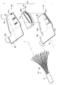
- FIG. 1 is a schematic configuration diagram of an ultrasonic endoscope
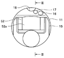
- FIG. 2 is an end view of a distal end rigid portion
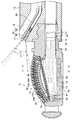
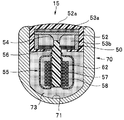
- FIG. 3 is a sectional view taken along line III-III in FIG. 4 is a sectional view taken along the line IV-IV in FIG. 3
- FIG. 5 is an exploded side view showing the vibrator unit and the housing to which the cable unit is connected
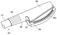
- FIG. 6 is an exploded perspective view showing the wiring board and the cable unit.
- 7 is a perspective view of the wiring board to which the cable unit is connected
- FIG. 8 is an exploded perspective view showing a modification of the wiring board and the cable unit
- FIG. 9 is a perspective view showing a modification of the flexible sheet.
- An ultrasonic endoscope system 1 shown in FIG. 1 includes an ultrasonic endoscope 2, an ultrasonic observation device 3, and a monitor 4.
- the ultrasonic endoscope 2 includes an elongated insertion portion 10 to be inserted into the body, an operation portion 20 connected to the proximal end of the insertion portion 10, and a universal cord extending from a side portion of the operation portion 20. 30.
- a connector 31 connected to a light source device (not shown) is provided at the base end of the universal cord 30.
- a cable 32 connected to a camera control unit (not shown) via a connector 32a and a cable 33 detachably connected to the ultrasonic observation apparatus 3 via a connector 33a extend from the connector 31.
- the ultrasonic endoscope 2 is connected to an ultrasonic observation device 3 via a connector 33a, and further connected to a monitor 4 via the ultrasonic observation device 3.
- the insertion portion 10 is, in order from the distal end side, a distal end rigid portion 11, a bending portion 12 positioned at the rear end of the distal end rigid portion 11, and a small diameter and long length that is positioned at the rear end of the bending portion 12 and reaches the operation portion 20.
- a flexible tube portion 13 having flexibility with a scale is connected to form a main portion.
- an ultrasonic probe 15 is disposed on the distal end side of the distal rigid portion 11. Furthermore, on the base side of the ultrasonic probe 15, on the inclined surface formed in the distal end rigid portion 11, an illumination lens 16 constituting an illumination optical system, an observation lens 17 of the observation lens optical system, A forceps port 18 also serving as a suction port and an air / water supply nozzle (not shown) are provided.
- the operation unit 20 includes an angle knob 21 that controls the bending unit 12 to bend in a desired direction, an air / water supply button 22 that performs air supply and water supply operations, a suction button 23 that performs suction operations, and a treatment that is introduced into the body.
- a treatment instrument insertion port 24 serving as an instrument entrance is disposed.
- the treatment instrument insertion port 24 communicates with the forceps port 18 via a treatment instrument insertion channel (not shown) provided in the insertion portion 10.
- the ultrasonic probe 15 of the present embodiment is a convex type ultrasonic probe, and the ultrasonic probe 15 is, for example, a transducer that transmits and receives ultrasonic waves.
- the unit 50 includes a cable unit 60 that is electrically connected to the vibrator unit 50 and a housing 70 that holds the vibrator unit 50.
- the transducer unit 50 includes an ultrasonic transmission / reception unit 51 arranged in a substantially arc shape with the long sides of a plurality of elongated ultrasonic transducer elements 51a connected to each other.
- the ultrasonic transmission / reception unit 51 is accommodated in a protective cover 52 in which a substantially arc-shaped acoustic lens layer 52a is integrally provided.
- each ultrasonic transducer element 51a is disposed to face the inner surface of the acoustic lens layer 52a, and is bonded via the acoustic matching layer 53a.
- one end portion of the wiring board 55 faces the back side of each ultrasonic transducer element 51a.
- One end portion of the wiring board 55 is provided with an electrode portion 56a corresponding to each ultrasonic transducer element 51a.
- the ultrasonic transducer element 51a is electrically connected to the electrode portion 56a via the wiring wire 54. Connected mechanically and mechanically. For the connection of these wiring wires 54, soldering or the like is preferably used.
- a back braking layer (backing layer) 53b is formed in the protective cover 52 by, for example, filling an adhesive having a predetermined elasticity, and the wiring wires 54 are sealed by the back braking layer 53b. Has been.
- the wiring board 55 is specifically composed of a rigid circuit board 56 as a rigid portion and a pair of flexible circuit boards that are respectively attached to both sides of the rigid circuit board 56. 57.
- wiring patterns each including the above-described electrode portions 56a and a plurality of pad electrodes 56b electrically connected to the electrode portions 56a are formed on both surfaces thereof.
- each flexible circuit board 57 a plurality of inner electrode portions 57a corresponding to the pad electrodes 56b are arranged on one surface (inner surface side) facing the rigid circuit substrate 56, and each on the other surface (outer surface) side.
- a wiring pattern is formed in which a plurality of outer electrode portions 57b that are electrically connected to the inner electrode portions 57a are arranged.
- a protective sheet 58 is formed that has a shape that is substantially line symmetrical with the flexible circuit board 57.
- a band-shaped covering portion 59 is extended.
- the protective sheet 58 and the covering portion 59 are made of, for example, a flexible and insulating sheet material, and are integrally formed with the flexible circuit board 57.
- each flexible circuit board 57 is attached to each surface of the rigid circuit board 56.
- the flexible circuit board 57 is attached in a state where the inner electrode portions 57a on the flexible circuit board 57 are positioned with respect to the pad electrodes 56b on the rigid circuit board 56. This is done by thermocompression bonding or soldering to 56. Then, the flexible circuit board 57 is attached to the rigid circuit board 56 in this manner, whereby each inner electrode portion 57a on each flexible circuit board 57 is electrically connected to each pad electrode 56b on the rigid circuit board 56. It is connected.
- the adhesive used for thermocompression bonding of the rigid circuit board 56 and the flexible circuit board 57 is preferably a crosslinkable adhesive.
- the cable unit 60 is constituted by a wiring group in which a plurality of drive wirings 62 made of, for example, a small-diameter coaxial cable are integrally bundled by an outer skin 61. At the distal end portion of the cable unit 60, each drive wiring 62 extends from the outer skin 61 and is branched individually. The leading ends of the branched drive wires 62 are electrically connected to the outer electrode portions 57b on the outer surface side of the flexible circuit boards 57, respectively. Each drive wiring 62 is electrically connected to each ultrasonic transducer element 51a through connection to each of the outer electrode portions 57b. Note that soldering or the like is preferably used as the connection of the drive wirings 62.
- each drive wiring 62 of the cable unit 60 is electrically connected to each outer electrode portion 57b
- the protective sheet 58 extended from each flexible circuit board 57 covers each outer electrode portion 57b.
- the front end portion is bonded to the rigid circuit board 56 via, for example, an adhesive 58a (see FIG. 4).
- an adhesive 58a see FIG. 4
- the covering portion 59 extending from one flexible circuit board 57 is wound around the peripheral portion of each drive wiring 62 exposed from the outer skin 61.
- the tip of the covering portion 59 is the covering portion.
- the middle part of 59 is bonded via an adhesive 59a.
- the drive wires 62 exposed from the outer skin 61 are integrally wrapped and bundled by the covering portion 59 (see FIGS. 5 and 7), and the drive wires 62 are mechanically protected and electrically shielded. Is done.
- the housing 70 is constituted by a member having a substantially “U-shaped” cross section in which the accommodating portion 71 of the vibrator unit 50 is recessed, for example.
- a pipe-like wiring insertion portion 72 having a function as a connector with the distal end rigid portion 11 is provided, and the inside of the wiring insertion portion 72 is communicated with the housing portion 71. Yes.
- the proximal end side of the cable unit 60 is inserted into the wiring insertion portion 72 from the accommodating portion 71 side. Thereafter, the operation of housing the vibrator unit 50 in the housing portion 71 is performed together with the insertion operation of pushing the driving wires 62 integrally wrapped and bundled by the covering portion 59 into the wiring insertion portion 72. After the vibrator unit 50 is accommodated in the accommodating portion 71, the accommodating portion 71 is filled with, for example, the resin adhesive 73 through the wiring insertion portion 72.
- the wiring board 55 that is electrically connected to the back side of the ultrasonic transmission / reception unit 51 that transmits / receives ultrasonic waves, the rigid circuit board 56 that constitutes the rigid part, and the rigid circuit board 56 A wiring portion of the housing 70 in a state in which a plurality of drive wirings 62 electrically connected to the wiring board 55 are wrapped and bundled by the covering portion 59.
- the ultrasonic probe 15 can be sufficiently miniaturized with a simple configuration without impairing assemblability.
- the covering portion 59 is formed integrally with the flexible circuit board 57, so that a dedicated sheet material or the like is formed. Without using the cover portion 59, the covering portion 59 can be extended from the rigid portion (the rigid circuit board 56) with a simpler configuration. Moreover, if the covering portion 59 is formed integrally with the flexible circuit board 57 in this way, it is not necessary to secure a space for bonding the base end side of the covering portion 59 on the rigid circuit board 56, Accordingly, the wiring board 55 can be reduced in size.
- the base end of the protection sheet 58 is provided on the rigid circuit board 56. It is not necessary to secure a space for bonding the sides, and the wiring board 55 can be reduced in size accordingly.
- the covering portion 59 is provided on one of the pair of flexible circuit boards 57, and all of the drive wirings 62 connected to both the flexible circuit boards 57 are integrally wrapped and bundled.
- FIG. 8 it is also possible to form a covering portion 59 integrally on each flexible circuit board 57 and wrap and bundle each drive wiring 62 for each flexible circuit board 57. It is.
- the ultrasonic endoscope 2 when observing an optical image in a subject with this type of ultrasonic endoscope 2, it is desirable to prevent the ultrasonic probe 15 from being reflected in the optical image.
- the optical axis of the observation optical lens system disposed in the distal end rigid portion 11 is 35 to 55 on the UP side (upward) with respect to the longitudinal axis direction of the insertion portion 10. It is arranged to incline at a relatively steep angle of the order of degrees.
- such an inclination angle is to be realized in the narrow tip rigid portion 11.
- the image guide bundle 80 must be bent with a large curvature, and a bending load is applied to the bending portion.
- the optical axis O2 of the image guide bundle lens 83 fixed to the lens is offset to the UP side.
- the base 85 provided at the distal end portion of the image guide bundle 80 has a lens in which a fitting portion 86a with respect to the base 85 and a lens holding portion 86b connected to the base 85 are eccentric.
- a frame 86 is fitted. Further, by holding the image guide bundle lens 83 through the lens frame 86, for example, as shown in FIG.
- the image guide bundle lens 83 is positioned by providing a positioning projection 85 a at a part of the tip of the base 85 and using this projection 85 a as a reference. Is also possible.
Abstract
超音波を送受信する超音波送受信部51の背面側に電気的接続される配線基板55を、剛性部を構成するリジッド回路基板56と、このリジット回路基板56(剛性部)から延出された包被部59とを備えた構成とし、配線基板55に電気的に接続される複数の駆動配線62を、包被部59によって包み束ねた状態でハウジング70の配線挿通部72に挿入する。
Description
本発明は、挿入部の先端部に設けられたハウジング内に振動子ユニットが収容された超音波内視鏡に関する。
従来、医療分野等においては、細長の内視鏡挿入部の先端に超音波探触子を備えた超音波内視鏡が広く利用されている。この超音波内視鏡は、例えば、超音波観測装置やモニタ等とともに超音波内視鏡システムを構成する。そして、この超音波内視鏡システムでは、例えば、超音波探触子から被検体に超音波を送信し、受信した超音波エコー信号を超音波観測装置で処理することにより、被検体内の超音波断層像を取得することが可能となっている。
このような超音波内視鏡に用いられる超音波探触子は、例えば、複数の超音波振動子が音響整合層や背面制動層等とともにユニット化された振動子ユニットを有し、この振動子ユニットが、ハウジング内に形成された収容部に収容されることによって要部が構成されている。ここで、振動子ユニットには各超音波振動子と電気的に接続する配線基板が設けられており、この配線基板上の各端子に、各超音波振動子に対応してケーブルユニットから分岐された複数の駆動配線が、それぞれ電気的に接続されている。また、ケーブルユニットを内視鏡の挿入部内に配索するため、ハウジング内に形成された振動子ユニットの収容部には、管路状の配線挿通部(パイプ部)が連通されている(例えば、日本国特開2004-209044号公報参照)。そして、このような超音波探触子を組み立てる場合、先ず、ケーブルユニットの基端側が収容部側から配線挿通部内に挿通され、その後、ケーブルユニットの先端部から分岐する駆動配線群を配線挿通部内に押し込む作業とともに、振動子ユニットをハウジングの収容部内に収容する作業が行われる。
ところで、この種の超音波内視鏡においては、超音波探触子の小型化が強く求められており、その対策として、例えば、振動子ユニットから配線挿通部の口元までの距離の短縮や、配線挿通部の細径化等を行うことが考えられる。
しかしながら、各駆動配線は振動子ユニットの配線基板上に直線状かつ多層に配置されているため、これら複数の駆動配線を円筒状の配線挿通部内に一体的に収納することは容易ではない。しかも、超音波内視鏡の駆動配線は極めて細径の同軸ケーブル等で構成されているため、個々の駆動配線を大きな曲率で湾曲させながら配線挿通部の口元に押し込む際には、断線等に対して十分な注意が必要となる。
従って、振動子ユニットから配線挿通部の口元までの距離の短縮や、配線挿通部の細径化等によって超音波探触子を小型化するには限界があった。
本発明は上記事情に鑑みてなされたもので、簡単な構成により、組立性を損なうことなく、超音波探触子を十分に小型化することができる超音波内視鏡を提供することを目的とする。
本発明の一態様による超音波内視鏡は、超音波を送受信する超音波送受信部と、前記超音波送受信部の背面側に電気的に接続された少なくとも一枚の配線基板と、前記配線基板に電気的に接続された複数の駆動配線と、前記配線基板を収容して前記超音波送受信部を保持するハウジングと、を備え、前記ハウジングは、前記配線基板を収容する収容部と、前記収容部に連通され、前記収容部よりも細径な管路状の配線挿通部と、を含み、前記配線基板は、前記超音波送受信部の背面側に電気的に接続される剛性部と、前記剛性部から延出され、前記複数の駆動配線を包み束ねて前記配線挿通部に挿入される包被部と、を含むものである。
以下、図面を参照して本発明の形態を説明する。図面は本発明の一実施形態に係わり、図1は超音波内視鏡の概略構成図、図2は先端硬性部の端面図、図3は図2のIII-III線に沿う断面図、図4は図3のIV-IV線に沿う断面図、図5はケーブルユニットが接続された振動子ユニットとハウジングとを分解して示す側面図、図6は配線基板とケーブルユニットを示す分解斜視図、図7はケーブルユニットが接続された配線基板の斜視図、図8は配線基板とケーブルユニットの変形例を示す分解斜視図、図9は可撓性シートの変形例を示す斜視図である。
図1に示す超音波内視鏡システム1は、超音波内視鏡2と、超音波観測装置3と、モニタ4と、を具備して構成されている。また、超音波内視鏡2は、体内に挿入される細長の挿入部10と、挿入部10の基端に連設された操作部20と、操作部20の側部から延出するユニバーサルコード30と、を有して構成されている。
ここで、ユニバーサルコード30の基端部には、光源装置(図示せず)に接続されるコネクタ31が設けられている。コネクタ31からは、カメラコントロールユニット(図示せず)にコネクタ32aを介して接続されるケーブル32と、超音波観測装置3にコネクタ33aを介して着脱自在に接続されるケーブル33と、が延出されている。そして、超音波内視鏡2には、コネクタ33aを介して超音波観測装置3が接続され、さらに、超音波観測装置3を介してモニタ4が接続されている。
挿入部10は、先端側から順に、先端硬性部11と、先端硬性部11の後端に位置する湾曲部12と、湾曲部12の後端に位置して操作部20に至る細径かつ長尺で可撓性を有する可撓性管部13と、が連設されて要部が構成されている。
図2に示すように、先端硬性部11の先端側には超音波探触子15が配設されている。さらに、超音波探触子15よりも基部側において、先端硬性部11に形成された傾斜面には、照明光学系を構成する照明用レンズ16と、観察レンズ光学系の観察用レンズ17と、吸引口を兼用する鉗子口18と、図示しない送気送水ノズルと、が配設されている。
操作部20には、湾曲部12を所望の方向に湾曲制御するアングルノブ21と、送気および送水操作を行う送気送水ボタン22と、吸引操作を行う吸引ボタン23と、体内に導入する処置具の入口となる処置具挿入口24と、が配設されている。ここで、処置具挿入口24は、挿入部10の内部に設けられた処置具挿通チャンネル(図示せず)を介して鉗子口18に連通されている。
図2乃至図5に示すように、本実施形態の超音波探触子15はコンベックス型の超音波探触子であり、この超音波探触子15は、例えば、超音波を送受信する振動子ユニット50と、この振動子ユニット50と電気的に接続するケーブルユニット60と、振動子ユニット50を保持するハウジング70と、を有して構成されている。
振動子ユニット50は、複数の細長い超音波振動子エレメント51aの長辺が連結された状態で、略円弧状に配置された超音波送受信部51を有する。この超音波送受信部51は、略円弧状の音響レンズ層52aが一体的に設けられた保護カバー52内に収容されている。保護カバー52内において、各超音波振動子エレメント51aは、音響レンズ層52aの内面に対向して配置され、音響整合層53aを介して接着されている。
また、保護カバー52内において、各超音波振動子エレメント51aの背面側には、配線基板55の一端部が臨まされている。この配線基板55の一端部には、各超音波振動子エレメント51aに対応する電極部56aが設けられ、これらの電極部56aには、超音波振動子エレメント51aが配線ワイヤ54を介して、電気的かつ機械的に接続されている。なお、これらの配線ワイヤ54の接続としては、半田付け等が好適に用いられる。さらに、保護カバー52内には、例えば、所定の弾性を有する接着剤等を充填することによって背面制動層(バッキング層)53bが形成され、この背面制動層53bにより、各配線ワイヤ54が封止されている。
ここで、例えば、図6に示すように、配線基板55は、具体的には、剛性部としてのリジット回路基板56と、このリジット回路基板56の両面にそれぞれ貼着される一対のフレキシブル回路基板57とを有して構成されている。
リジット回路基板56には、上述の各電極部56aと、これら電極部56aにそれぞれ電気的に接続する複数のパッド電極56bと、を備えた配線パターンがその両面に形成されている。
各フレキシブル回路基板57には、リジット回路基板56と対向する一方の面(内面側)にパッド電極56bに対応する複数の内側電極部57aが配列され、且つ、他方の面(外面)側に各内側電極部57aにそれぞれ電気的に接続する複数の外側電極部57bが配列された配線パターンが形成されている。また、各フレキシブル回路基板57からは、当該フレキシブル回路基板57と略線対称の形状をなす保護シート58が延出されている。さらに、一方のフレキシブル回路基板57からは、帯状の包被部59が延出されている。これら保護シート58及び包被部59は、例えば、可撓性を有し且つ絶縁性を有するシート材によって構成されるものであり、フレキシブル回路基板57と一体形成されている。
各フレキシブル回路基板57の内面側は、リジット回路基板56の各面にそれぞれ貼着されている。これらフレキシブル回路基板57の貼着は、例えば、リジット回路基板56上の各パッド電極56bに対してフレキシブル回路基板57上の各内側電極部57aを位置決めした状態で、フレキシブル回路基板57がリジット回路基板56に熱圧着またはハンダ付けされることによって行われる。そして、このようにフレキシブル回路基板57がリジット回路基板56に貼着されることにより、各フレキシブル回路基板57上の各内側電極部57aは、リジット回路基板56上の各パッド電極56bと電気的に接続されている。なお、リジット回路基板56とフレキシブル回路基板57との熱圧着に用いられる接着剤は、架橋性接着剤であることが望ましい。
ケーブルユニット60は、例えば、細径の同軸ケーブルからなる複数の駆動配線62が外皮61によって一体的に束ねられた配線群によって構成されている。このケーブルユニット60の先端部において、各駆動配線62は、外皮61から延出され、個々に分岐されている。そして、これら分岐された各駆動配線62の先端部は、各フレキシブル回路基板57の外面側において、各外側電極部57bとそれぞれ電気的に接続されている。そして、これら各外側電極部57bとの接続を通じて、各駆動配線62は、各超音波振動子エレメント51aに電気的に接続されている。なお、これらの駆動配線62の接続としては、半田付け等が好適に用いられる。
ここで、ケーブルユニット60の各駆動配線62が各外側電極部57bと電気的に接続された後において、各フレキシブル回路基板57から延出された保護シート58は、各外側電極部57bを覆うように折り返され、その先端部が、例えば、接着剤58aを介してリジット回路基板56に接着されている(図4参照)。これにより、各外側電極部57bと各駆動配線62との接続部が機械的に保護されるとともに電気的にシールドされる。
さらに、一方のフレキシブル回路基板57から延出された包被部59は、外皮61から露出する各駆動配線62の周部に巻回され、例えば、包被部59の先端部が当該包被部59の中途部に接着剤59aを介して接着されている。これにより、外皮61から露出した各駆動配線62は、包被部59によって一体的に包み束ねられ(図5,7参照)、これら各駆動配線62が機械的に保護されるとともに電気的にシールドされる。
図3乃至図5に示すように、ハウジング70は、例えば、振動子ユニット50の収容部71が凹設された、断面略「U字状」をなす部材で構成されている。このハウジング70の基部側には、先端硬性部11とのコネクタとしての機能を備えた管路状の配線挿通部72が設けられ、この配線挿通部72の内部が収容部71内に連通されている。
このようなハウジング70に対し、振動子ユニット50を組み立てる場合、例えば、図5に示すように、先ず、ケーブルユニット60の基端側が収容部71側から配線挿通部72内に挿通される。その後、包被部59によって一体的に包み束ねられた各駆動配線62を配線挿通部72内に押し込む挿入作業とともに、振動子ユニット50を収容部71内に収容する作業が行われる。なお、振動子ユニット50が収容部71内に収容された後において、当該収容部71内には、例えば、配線挿通部72を通じて樹脂接着剤73が充填される。
このような実施形態によれば、超音波を送受信する超音波送受信部51の背面側に電気的接続される配線基板55を、剛性部を構成するリジッド回路基板56と、このリジット回路基板56(剛性部)から延出された包被部59とを備えた構成とし、配線基板55に電気的に接続される複数の駆動配線62を、包被部59によって包み束ねた状態でハウジング70の配線挿通部72に挿入することにより、簡単な構成により、組立性を損なうことなく、超音波探触子15を十分に小型化することができる。
すなわち、複数の駆動配線62を包被部59によって包み束ねることにより、各駆動配線62を配線挿通部72内に押し込む際に、当該配線挿通部70の口元等と各駆動配線62との直接的な干渉を回避することができる。従って、例えば、超音波探触子15の組立時に、極めて細径の各駆動配線62を、配線挿通部72の口元等に対して比較的大きな曲率で湾曲させながら押し当てたとしても、各駆動配線62の機械的な損傷等を格段に低減することができる。従って、例えば、振動子ユニット50から配線挿通部72の口元までの距離の短縮や、配線挿通部72の細径か等を容易に実現することができ、超音波探触子15を十分に小型化することができる。
ここで、リジット回路基板56にフレキシブル回路基板57を介して各駆動配線62を電気的に接続する構成においては、包被部59をフレキシブル回路基板57と一体形成することにより、専用のシート材等を用いることなく、より簡単な構成によって剛性部(リジット回路基板56)から包被部59を延出させることができる。しかも、このように、包被部59をフレキシブル回路基板57と一体形成すれば、リジット回路基板56上に包被部59の基端側を接着するためのスペース等を確保する必要がなく、その分、配線基板55を小型化することができる。
また、各駆動配線62の接続部を機械的に保護するとともに電気的に絶縁するための保護シート58をフレキシブル回路基板57から延出させることにより、リジット回路基板56上に保護シート58の基端側を接着するためのスペースを確保する必要がなく、その分、配線基板55を小型化することができる。
ここで、上述の実施形態においては、一対のフレキシブル回路基板57のうちの一方に包被部59を設け両フレキシブル回路基板57に接続される各駆動配線62の全てを一体的に包み束ねる構成の一例について説明したが、例えば、図8に示すように、各フレキシブル回路基板57それぞれに包被部59を一体形成し、フレキシブル回路基板57毎に各駆動配線62を包み束ねる構成とすることも可能である。
また、上述の実施形態においては、包被部59の先端部を接着剤59aを用いて接着する構成の一例について説明したが、例えば、接着剤59aに代えて粘着テープ(図示せず)等を用いることも可能である。さらに、例えば、図9に示すように、包被部59にスリット部59bを設け、このスリット部59bの係合によって包被部59の巻装状態を保持する構成とすることも可能である。
ところで、この種の超音波内視鏡2において、被検体内の光学画像を観察する場合、当該光学画像中への超音波探触子15の映り込みを防止することが望ましい。その対策として、超音波内視鏡2では、一般に、先端硬性部11に配置される観察光学レンズ系の光軸は、挿入部10の長手軸方向に対してUP側(上方)に35~55度程度の比較的急峻な角度で傾斜するよう配置される。しかしながら、特に、イメージガイドバンドル80を用いて光学画像を操作部20側に伝送する光学式を採用した超音波内視鏡2において、このような傾斜角度を狭隘な先端硬性部11内において実現しようとすると、イメージガイドバンドル80を大きな曲率で湾曲させなければならず、当該湾曲部位に湾曲負荷がかかってしまう。その一方で、得られる光学画像の画角を小さく設定したり、先端硬性部11の長手軸方向の寸法を大きく設定することは、実用上好ましくない。
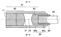
そこで、このような課題を解消すべく、例えば、図10,11に示す観察光学レンズ系81では、観察用レンズ17を含む対物レンズ群82の光軸O1に対し、イメージガイドバンドル80の先端部に固設するイメージガイドバンドルレンズ83の光軸O2がUP側にオフセットして配置されている。このようなオフセット状態を実現するため、イメージガイドバンドル80の先端部に設けられた口金85には、当該口金85に対する嵌合部86aと、これに連設するレンズ保持部86bとが偏心したレンズ枠86が嵌合されている。そして、このレンズ枠86を介してイメージガイドバンドルレンズ83が保持されることにより、例えば、図3に示すように、イメージガイドバンドル80を比較的小さな曲率で湾曲させた場合にも、画角αを小さく設定することなく、且つ、先端硬性部11の長手軸方向の寸法を大きく設定することなく、光学画像内への超音波探触子15の映り込みを防止することができる(図3中の一点鎖線参照)。なお、図3中において、二点鎖線で示す領域は、比較例として、イメージガイドバンドルレンズ83をオフセットさせなかったときの観察可能範囲を示すものである。
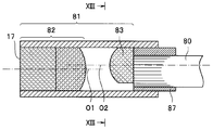
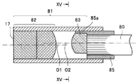
ここで、このようなイメージガイドバンドルレンズ83の位置決めは、例えば、図12,13に示すように、口金87のイメージガイドバンドル80との嵌合孔を偏心させ、偏心させた口金87の外周面を基準として行うことも実現が可能である。さらに、例えば、図14,15に示すように、イメージライトガイドバンドルレンズ83の位置決めは、口金85の先端部の一部に位置決め用の突起部85aを設け、この突起部85aを基準として行うことも可能である。
なお、本発明は、以上説明した実施形態に限定されることなく、種々の変形や変更が可能であり、それらも本発明の技術的範囲内である。
本出願は、2012年8月27日に日本国に出願された特願2012-186871号を優先権主張の基礎として出願するものであり、上記の内容は、本願明細書、請求の範囲、および図面に引用されたものである。
Claims (4)
- 超音波を送受信する超音波送受信部と、
前記超音波送受信部の背面側に電気的に接続された少なくとも一枚の配線基板と、
前記配線基板に電気的に接続された複数の駆動配線と、
前記配線基板を収容して前記超音波送受信部を保持するハウジングと、を備え、
前記ハウジングは、
前記配線基板を収容する収容部と、
前記収容部に連通され、前記収容部よりも細径な管路状の配線挿通部と、を含み、
前記配線基板は、
前記超音波送受信部の背面側に電気的に接続される剛性部と、
前記剛性部から延出され、前記複数の駆動配線を包み束ねて前記配線挿通部に挿入される包被部と、を含むことを特徴とする超音波内視鏡。 - 前記配線基板は、前記超音波送受信部の背面側に電気的に接続されて前記剛性部を構成するリジット回路基板と、
一方の面が前記リジット回路基板に電気的に接続されるとともに、他方の面に前記複数の駆動配線が電気的に接続されるフレキシブル回路基板と、を含み、
前記包被部は、前記フレキシブル回路基板と一体形成されていることを特徴とする請求項1に記載の超音波内視鏡。 - 前記配線基板は、前記剛性部から延出されて前記複数の駆動配線との接続部を覆う保護シートを含むことを特徴とする請求項1に記載の超音波内視鏡。
- 前記配線基板は、前記剛性部から延出されて前記複数の駆動配線との接続部を覆う保護シートを含み、
前記保護シートは、前記フレキシブル回路基板及び前記包被部と一体形成されていることを特徴とする請求項2に記載の超音波内視鏡。
Priority Applications (4)
| Application Number | Priority Date | Filing Date | Title |
|---|---|---|---|
| CN201380001744.9A CN103764043B (zh) | 2012-08-27 | 2013-05-17 | 超声波内窥镜 |
| JP2013536349A JP5399594B1 (ja) | 2012-08-27 | 2013-05-17 | 超音波内視鏡 |
| EP13795683.5A EP2740411A4 (en) | 2012-08-27 | 2013-05-17 | ULTRASOUND ENDOSCOPE |
| US13/965,414 US9050052B2 (en) | 2012-08-27 | 2013-08-13 | Ultrasound endoscope |
Applications Claiming Priority (2)
| Application Number | Priority Date | Filing Date | Title |
|---|---|---|---|
| JP2012-186871 | 2012-08-27 | ||
| JP2012186871 | 2012-08-27 |
Related Child Applications (1)
| Application Number | Title | Priority Date | Filing Date |
|---|---|---|---|
| US13/965,414 Continuation US9050052B2 (en) | 2012-08-27 | 2013-08-13 | Ultrasound endoscope |
Publications (1)
| Publication Number | Publication Date |
|---|---|
| WO2014034191A1 true WO2014034191A1 (ja) | 2014-03-06 |
Family
ID=50183018
Family Applications (1)
| Application Number | Title | Priority Date | Filing Date |
|---|---|---|---|
| PCT/JP2013/063807 WO2014034191A1 (ja) | 2012-08-27 | 2013-05-17 | 超音波内視鏡 |
Country Status (3)
| Country | Link |
|---|---|
| EP (1) | EP2740411A4 (ja) |
| CN (1) | CN103764043B (ja) |
| WO (1) | WO2014034191A1 (ja) |
Cited By (3)
| Publication number | Priority date | Publication date | Assignee | Title |
|---|---|---|---|---|
| WO2018230274A1 (ja) * | 2017-06-12 | 2018-12-20 | オリンパス株式会社 | 内視鏡 |
| WO2019026691A1 (ja) * | 2017-08-03 | 2019-02-07 | オリンパス株式会社 | 超音波内視鏡 |
| WO2019146331A1 (ja) * | 2018-01-29 | 2019-08-01 | 富士フイルム株式会社 | 超音波内視鏡及び超音波内視鏡の製造方法 |
Families Citing this family (6)
| Publication number | Priority date | Publication date | Assignee | Title |
|---|---|---|---|---|
| CN106456133B (zh) * | 2014-11-21 | 2019-09-17 | 奥林巴斯株式会社 | 超声波振子、超声波内窥镜 |
| EP3266379A4 (en) * | 2015-03-04 | 2018-12-05 | Olympus Corporation | Suction power adjusting device for ultrasound observation and ultrasound endoscope |
| WO2016208250A1 (ja) * | 2015-06-23 | 2016-12-29 | オリンパス株式会社 | 超音波内視鏡 |
| WO2017040692A1 (en) * | 2015-09-01 | 2017-03-09 | Deka Products Limited Partnership | Endoscope with pannable camera and related method |
| WO2018016128A1 (ja) * | 2016-07-19 | 2018-01-25 | オリンパス株式会社 | 超音波プローブ |
| CN108272469B (zh) * | 2017-12-22 | 2021-02-26 | 深圳先进技术研究院 | 一种双频率血管内超声成像探头 |
Citations (5)
| Publication number | Priority date | Publication date | Assignee | Title |
|---|---|---|---|---|
| JPH01291846A (ja) * | 1988-05-18 | 1989-11-24 | Aloka Co Ltd | 超音波探触子 |
| JPH0515536A (ja) * | 1991-07-05 | 1993-01-26 | Olympus Optical Co Ltd | 超音波探触子 |
| JP2003033354A (ja) * | 2001-05-14 | 2003-02-04 | Hitachi Medical Corp | 体腔内超音波探触子 |
| JP2004209044A (ja) | 2003-01-06 | 2004-07-29 | Olympus Corp | 超音波内視鏡 |
| JP2005218519A (ja) * | 2004-02-03 | 2005-08-18 | Olympus Corp | 超音波振動子ユニット |
Family Cites Families (7)
| Publication number | Priority date | Publication date | Assignee | Title |
|---|---|---|---|---|
| FR2543817B1 (fr) * | 1983-04-06 | 1986-06-27 | Rabelais Universite Francois | Sonde endoscopique de visualisation et d'echographie ultrasonore a balayage |
| JP2790253B2 (ja) * | 1989-04-13 | 1998-08-27 | オリンパス光学工業株式会社 | 電子走査型超音波プローブ |
| JP3378295B2 (ja) * | 1993-05-27 | 2003-02-17 | 株式会社東芝 | 超音波プロ−ブ及び超音波診断装置 |
| US20080084137A1 (en) * | 2005-10-05 | 2008-04-10 | Olympus Medical Systems Corp. | Electronic Radial Type Ultrasonic Transducer, Ultrasonic Endoscope and Its Production Method |
| JP4980653B2 (ja) * | 2006-06-12 | 2012-07-18 | オリンパスメディカルシステムズ株式会社 | 超音波探触子および超音波探触子を有する超音波内視鏡 |
| US20110166455A1 (en) * | 2010-01-07 | 2011-07-07 | Cully Edward H | Catheter |
| CN202235461U (zh) * | 2011-09-30 | 2012-05-30 | 汕头市超声仪器研究所有限公司 | 一种内窥镜超声探头 |
-
2013
- 2013-05-17 WO PCT/JP2013/063807 patent/WO2014034191A1/ja unknown
- 2013-05-17 EP EP13795683.5A patent/EP2740411A4/en not_active Withdrawn
- 2013-05-17 CN CN201380001744.9A patent/CN103764043B/zh active Active
Patent Citations (5)
| Publication number | Priority date | Publication date | Assignee | Title |
|---|---|---|---|---|
| JPH01291846A (ja) * | 1988-05-18 | 1989-11-24 | Aloka Co Ltd | 超音波探触子 |
| JPH0515536A (ja) * | 1991-07-05 | 1993-01-26 | Olympus Optical Co Ltd | 超音波探触子 |
| JP2003033354A (ja) * | 2001-05-14 | 2003-02-04 | Hitachi Medical Corp | 体腔内超音波探触子 |
| JP2004209044A (ja) | 2003-01-06 | 2004-07-29 | Olympus Corp | 超音波内視鏡 |
| JP2005218519A (ja) * | 2004-02-03 | 2005-08-18 | Olympus Corp | 超音波振動子ユニット |
Non-Patent Citations (1)
| Title |
|---|
| See also references of EP2740411A4 * |
Cited By (4)
| Publication number | Priority date | Publication date | Assignee | Title |
|---|---|---|---|---|
| WO2018230274A1 (ja) * | 2017-06-12 | 2018-12-20 | オリンパス株式会社 | 内視鏡 |
| WO2019026691A1 (ja) * | 2017-08-03 | 2019-02-07 | オリンパス株式会社 | 超音波内視鏡 |
| WO2019146331A1 (ja) * | 2018-01-29 | 2019-08-01 | 富士フイルム株式会社 | 超音波内視鏡及び超音波内視鏡の製造方法 |
| JPWO2019146331A1 (ja) * | 2018-01-29 | 2020-12-03 | 富士フイルム株式会社 | 超音波内視鏡及び超音波内視鏡の製造方法 |
Also Published As
| Publication number | Publication date |
|---|---|
| EP2740411A4 (en) | 2015-04-15 |
| CN103764043B (zh) | 2015-09-09 |
| CN103764043A (zh) | 2014-04-30 |
| EP2740411A1 (en) | 2014-06-11 |
Similar Documents
| Publication | Publication Date | Title |
|---|---|---|
| JP5399594B1 (ja) | 超音波内視鏡 | |
| WO2014034191A1 (ja) | 超音波内視鏡 | |
| JP5253691B1 (ja) | 超音波内視鏡 | |
| WO2006082692A1 (ja) | 超音波内視鏡 | |
| WO2007145182A1 (ja) | 超音波探触子および超音波探触子を有する超音波内視鏡 | |
| JP2009153902A (ja) | 電子内視鏡 | |
| JP2011212161A (ja) | 固体撮像装置及び内視鏡装置 | |
| US20160278737A1 (en) | Ultrasound endoscope | |
| US10661310B2 (en) | Ultrasonic oscillator unit | |
| US9173636B2 (en) | Ultrasound probe | |
| WO2014091970A1 (ja) | 半導体装置接続構造、超音波モジュールおよび超音波モジュールを搭載した超音波内視鏡システム | |
| JP2002263056A (ja) | 内視鏡 | |
| US20190029646A1 (en) | Ultrasonic oscillator unit | |
| JP4339830B2 (ja) | 超音波内視鏡 | |
| JP5283343B2 (ja) | 超音波内視鏡 | |
| JP3586180B2 (ja) | 内視鏡形状検出プローブ | |
| JP5412061B2 (ja) | 医療用スコープ、および医療用スコープにおける先端部連結方法 | |
| JP4388485B2 (ja) | 電子ラジアル型超音波内視鏡 | |
| JP4647968B2 (ja) | 超音波内視鏡 | |
| US20240099691A1 (en) | Ultrasonic endoscope | |
| JP2001258831A (ja) | 像形成装置 | |
| JP2000166928A (ja) | 超音波内視鏡 | |
| JP2009089925A (ja) | 内視鏡 | |
| JP3722633B2 (ja) | 内視鏡 | |
| JP4488203B2 (ja) | 超音波内視鏡 |
Legal Events
| Date | Code | Title | Description |
|---|---|---|---|
| ENP | Entry into the national phase |
Ref document number: 2013536349 Country of ref document: JP Kind code of ref document: A |
|
| 121 | Ep: the epo has been informed by wipo that ep was designated in this application |
Ref document number: 13795683 Country of ref document: EP Kind code of ref document: A1 |
|
| NENP | Non-entry into the national phase |
Ref country code: DE |