WO2019026691A1 - Ultrasonic endoscope - Google Patents
Ultrasonic endoscope Download PDFInfo
- Publication number
- WO2019026691A1 WO2019026691A1 PCT/JP2018/027704 JP2018027704W WO2019026691A1 WO 2019026691 A1 WO2019026691 A1 WO 2019026691A1 JP 2018027704 W JP2018027704 W JP 2018027704W WO 2019026691 A1 WO2019026691 A1 WO 2019026691A1
- Authority
- WO
- WIPO (PCT)
- Prior art keywords
- electrically connected
- ultrasonic
- board
- piezoelectric elements
- wiring pads
- Prior art date
Links
Images

Classifications
-
- A—HUMAN NECESSITIES
- A61—MEDICAL OR VETERINARY SCIENCE; HYGIENE
- A61B—DIAGNOSIS; SURGERY; IDENTIFICATION
- A61B8/00—Diagnosis using ultrasonic, sonic or infrasonic waves
- A61B8/12—Diagnosis using ultrasonic, sonic or infrasonic waves in body cavities or body tracts, e.g. by using catheters
Definitions
- the present invention relates to an ultrasound endoscope.
- Ultrasound may be applied to observe the characteristics of the biological tissue or material to be observed.
- the ultrasonic observation apparatus can obtain information on the characteristics of the observation target by performing predetermined signal processing on ultrasonic echoes received from ultrasonic transducers that transmit and receive ultrasonic waves. .
- the ultrasonic transducer converts an electrical pulse signal into an ultrasonic pulse (acoustic pulse) and irradiates the observation target, and converts an ultrasonic echo reflected by the observation target into an electrical echo signal and outputs And a plurality of piezoelectric elements.
- ultrasonic echoes are acquired from the observation target by arranging a plurality of piezoelectric elements along a predetermined direction and electronically switching elements involved in transmission and reception.
- a substrate for electrically connecting the piezoelectric element and the flexible substrate is provided perpendicularly to the arrangement direction of the plurality of piezoelectric elements. Since this substrate is rigid, there is a problem that the miniaturization of the tip portion of the ultrasonic endoscope is hindered by this substrate.
- the present invention has been made in view of the above, and it is an object of the present invention to provide an ultrasonic endoscope having a compact tip.
- an ultrasonic endoscope includes a plurality of piezoelectric elements arranged in a curved surface with their longitudinal directions aligned, and the piezoelectric element A plurality of conducting wires whose one end is electrically connected to one end, a plurality of first wiring pads whose other ends are electrically connected, and the first wiring pad, respectively.
- a board having a plurality of second wiring pads electrically connected a flexible substrate having a plurality of wirings electrically connected to the plurality of second wiring pads, and a plurality of wirings And a plurality of coaxial cables electrically connected to each other.
- the board has the plurality of first wiring pads disposed on one surface, and the other surface has the plurality of second wiring pads. Are arranged.
- the ultrasonic endoscope according to one aspect of the present invention is characterized in that the plurality of piezoelectric elements are disposed between the two boards disposed to face each other.
- the flexible substrate has a shape connected to one sheet, and the plurality of second wiring pads respectively located on the outside of the two boards. Are electrically connected to each other.
- the plurality of piezoelectric elements, the plurality of conductive wires, and the board are accommodated in a housing in which a space is formed inside,
- the coaxial cable is electrically connected to the flexible substrate at the outside of the housing.
- the plurality of piezoelectric elements, the plurality of conductive wires, and the board are accommodated in a housing in which a space is formed inside,
- the coaxial cable is electrically connected to the flexible substrate inside the housing.
- a resin is filled between the housing and the board.
- an acoustic lens is formed on the opposite side of the surface of the plurality of piezoelectric elements to which the conducting wire is connected, and the acoustic lens It is characterized in that it is made of the same material as the resin.
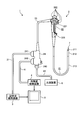
- FIG. 1 is a view schematically showing an endoscope system provided with an ultrasonic endoscope according to a first embodiment of the present invention.
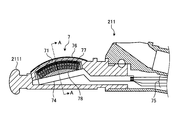
- FIG. 2 is a partial cross-sectional view of the distal end of the ultrasonic endoscope shown in FIG.
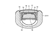
- FIG. 3 is a cross-sectional view corresponding to the line AA of FIG.
- FIG. 4 is an enlarged view of the board shown in FIG.
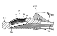
- FIG. 5 is a partial cross-sectional view of the distal end portion of the ultrasonic endoscope according to the second embodiment of the present invention.
- an embodiment of an ultrasound endoscope according to the present invention will be described with reference to the drawings. Note that the present invention is not limited by these embodiments.
- the present invention can be applied to ultrasound endoscopes in general provided with a convex-type ultrasound transducer.
- FIG. 1 is a view schematically showing an endoscope system provided with an ultrasonic endoscope according to a first embodiment of the present invention.
- the endoscope system 1 includes an ultrasonic endoscope 2, an ultrasonic observation device 3, an endoscopic observation device 4, a display device 5, and a light source device 6. .
- the ultrasonic endoscope 2 converts an electrical pulse signal received from the ultrasonic observation device 3 into an ultrasonic pulse (acoustic pulse) by an ultrasonic transducer, which will be described later, provided at the tip end of the ultrasonic endoscope 2 to be an object And converts the ultrasonic echo reflected by the object into an electrical echo signal represented by a voltage change and outputs it.
- the ultrasound endoscope 2 usually has an imaging optical system and an imaging element, and is inserted into the digestive tract (esophagus, stomach, duodenum, large intestine) or respiratory organ (trachea, bronchi) of a subject and digested It is possible to perform imaging of the tube and the respiratory system. Moreover, it is possible to image the surrounding organs (pancreas, gallbladder, bile duct, biliary tract, lymph nodes, mediastinal organs, blood vessels, etc.) using ultrasound.
- the ultrasound endoscope 2 has a light guide for guiding illumination light to be irradiated to the subject at the time of optical imaging.
- the light guide has a distal end portion reaching the distal end of the insertion portion of the ultrasonic endoscope 2 into the subject, while the proximal end portion is connected to the light source device 6 that generates illumination light.
- the ultrasound endoscope 2 includes an insertion unit 21, an operation unit 22, a universal cord 23, and a connector 24.
- the insertion unit 21 is a portion to be inserted into the subject.
- the insertion portion 21 is provided on the distal end side, and has a rigid distal end portion 211 for holding the ultrasonic transducer 7, a bending portion 212 connected to the base end side of the distal end portion 211 and being bendable, And a flexible tube portion 213 connected to the proximal end side and having flexibility.
- a light guide for transmitting illumination light supplied from the light source device 6 and a plurality of signal cables for transmitting various signals are drawn inside the insertion portion 21.
- a treatment instrument insertion path or the like for inserting the treatment instrument is formed.
- the ultrasonic transducer 7 is a convex-type ultrasonic transducer. Specifically, the ultrasonic endoscope 2 provides a plurality of piezoelectric elements as an array of ultrasonic transducers 7 in an array, electronically switches the piezoelectric elements involved in transmission and reception, and delays transmission and reception of each piezoelectric element It is a convex-type ultrasonic transducer that can be scanned electronically by The configuration of the ultrasonic transducer 7 will be described later.
- the operation unit 22 is connected to the proximal end side of the insertion unit 21 and is a portion that receives various operations from a doctor or the like. As shown in FIG. 1, the operation unit 22 includes a bending knob 221 for bending the bending portion 212 and a plurality of operation members 222 for performing various operations. Further, a treatment tool insertion port 223 is formed in the operation portion 22 so as to communicate with the treatment tool insertion path and for inserting the treatment tool in the treatment tool insertion path.
- the universal cord 23 is a cable which extends from the operation unit 22 and is provided with a plurality of signal cables for transmitting various signals, and an optical fiber for transmitting illumination light supplied from the light source device 6.
- the connector 24 is provided at the tip of the universal cord 23.
- the connector 24 has first to third connector portions 241 to 243 to which the ultrasonic cable 31, the video cable 41, and the optical fiber cable 61 are respectively connected.
- the ultrasound observation apparatus 3 is electrically connected to the ultrasound endoscope 2 via the ultrasound cable 31, and outputs a pulse signal to the ultrasound endoscope 2 via the ultrasound cable 31.
- An echo signal is input from the sound wave endoscope 2. Then, the ultrasonic observation device 3 performs predetermined processing on the echo signal to generate an ultrasonic image.
- the endoscope observation apparatus 4 is electrically connected to the ultrasound endoscope 2 via the video cable 41, and receives an image signal from the ultrasound endoscope 2 via the video cable 41. Then, the endoscope observation device 4 performs a predetermined process on the image signal to generate an endoscope image.
- the display device 5 is configured using a liquid crystal or organic EL (Electro Luminescence), a projector, a CRT (Cathode Ray Tube), or the like, and an ultrasound image generated by the ultrasound observation device 3 or the endoscope observation device 4 The endoscopic image etc. which were produced
- a liquid crystal or organic EL Electro Luminescence
- a projector a projector
- a CRT Cathode Ray Tube
- the light source device 6 is connected to the ultrasonic endoscope 2 via the optical fiber cable 61 and supplies illumination light for illuminating the inside of the subject via the optical fiber cable 61 to the ultrasonic endoscope 2.
- FIG. 2 is a partial cross-sectional view of the distal end of the ultrasonic endoscope shown in FIG.
- FIG. 3 is a cross-sectional view corresponding to the line AA of FIG.
- the ultrasonic transducer 7 is a convex-type ultrasonic vibration having a plurality of piezoelectric elements 71 arranged in a curved surface with their longitudinal directions (directions perpendicular to the sheet of FIG. 2) aligned. It is a child.
- the ultrasonic transducer 7 has a prismatic shape, and one end of one of the piezoelectric element 71 and the piezoelectric element 71 whose longitudinal direction is disposed orthogonal to the extending direction of the insertion portion 21 is electrically And the boards 73 (see FIG. 3) to which the other ends of the leads 72 are electrically connected, and the flexible lines electrically connected to the board 73.
- a substrate 74 and a plurality of coaxial cables 75 (see FIG. 2) electrically connected to the flexible substrate 74 are provided.
- the distal end (the plurality of piezoelectric elements 71, the plurality of conducting wires 72, and the board 73) of the ultrasonic transducer 7 is accommodated in a housing 2111 in which a space is formed.
- an acoustic lens 76 is formed on the opposite side of the surface of the plurality of piezoelectric elements 71 to which the conducting wire 72 is connected.
- resin 77 is filled between the housing 2111 and the board 73.
- the inside of the board 73 is filled with a resin 78.
- the housing 2111 is made of a hard material such as resin, and a space for housing the tip of the ultrasonic transducer 7 is formed inside.
- the piezoelectric element 71 is disposed between two boards 73 disposed to face each other.
- the piezoelectric element 71 converts an electrical pulse signal into an ultrasonic pulse (acoustic pulse) and irradiates the subject with an electrical echo signal that expresses an ultrasound echo reflected by the subject by a voltage change. Convert and output.
- an acoustic matching layer for matching the acoustic impedance of the piezoelectric element 71 with the observation target is provided. It may be provided.
- the conducting wire 72 is a conductor made of metal or alloy, and one end thereof is electrically connected to the piezoelectric element 71 by soldering or the like, and the other end is soldered to a first wiring pad of the board 73 described later. Are electrically connected.
- FIG. 4 is an enlarged view of the board shown in FIG.
- the two boards 73 disposed on both sides of the piezoelectric element 71 have sides having the same curvature as the curved surface formed by arranging the plurality of piezoelectric elements 71 (upper side in FIG.
- a plate-like member having a side of (B) of FIG. 4 is a view of (a) of FIG. 4 as viewed from the side (the left side of (a) of FIG. 4).
- the board 73 includes a hard plate-like substrate 731, a plurality of first wiring pads 732 formed on one surface of the substrate 731, and the other of the substrate 731. And a plurality of second wiring pads 733 formed on the surface.
- the substrate 731 is made of hard resin or the like and is disposed on both sides of the piezoelectric element 71. Furthermore, two boards are disposed at the end of the front end side and the rear end side of the piezoelectric element 71 (ends on the right side and the left side in FIG. 2), and a box-like space is formed by these four boards. Is formed. The resin 78 is filled in this space.
- the two boards 73 are arranged with the first wiring pads 732 facing each other.
- the first wiring pad 732 is electrically connected to one end of the conducting wire 72 (the end opposite to the end electrically connected to the piezoelectric element 71).
- the first wiring pad 732 and the second wiring pad 733 are electrically connected to each other by a conductor disposed through the substrate 731.
- the flexible substrate 74 has a plurality of wires electrically connected to the plurality of second wiring pads 733, respectively.
- the flexible substrate 74 has a shape of being connected to one sheet, and is electrically connected to a plurality of second wiring pads 733 respectively positioned on the outside of the two boards 73 disposed opposite to each other.
- the flexible substrate 74 is made of a flexible material, and is accommodated inside the housing 2111 in a curved or bent state.
- FIG. 3 shows a configuration in which the flexible substrate 74 is arranged in a state of being curved in an arc shape.
- the flexible substrate 74 may be disposed so as to be bent in a bellows shape, or may be disposed in a rectangular shape along the board 73.
- the flexible substrates 74 may be connected to, for example, two boards 73 one by one.
- the flexible substrate 74 may be divided into a plurality of pieces in the arrangement direction of the piezoelectric elements 71.
- the coaxial cable 75 is electrically connected to the flexible substrate 74 outside the housing 2111.
- the acoustic lens 76 is formed using silicone, polymethyl pentene, epoxy resin, polyether imide, or the like, and has a function of squeezing an ultrasonic wave by forming a convex or concave shape on one side.
- the acoustic lens 76 emits the ultrasonic wave emitted from the piezoelectric element 71 to the outside, or takes in an ultrasonic echo from the outside.
- the acoustic lens 76 can be optionally provided, and the acoustic lens 76 may not be provided.
- the resin 77 is made of, for example, the same material as that of the acoustic lens 76, but may be made of a material different from that of the acoustic lens 76.
- the resin 78 functions as a backing material that attenuates unnecessary ultrasonic vibrations generated by the operation of the piezoelectric element 71.
- the resin 78 is formed using a material having a large damping rate, for example, an epoxy resin in which a filler such as alumina or zirconia is dispersed, or a rubber in which the filler described above is dispersed.
- the ultrasonic transducer 7 having the above configuration vibrates the piezoelectric element 71 by the input of the pulse signal, and propagates through the acoustic lens 76 to irradiate the ultrasonic wave to the observation target.
- the unnecessary vibration from the piezoelectric element 71 is attenuated by the resin 78.
- the ultrasonic wave reflected from the observation target propagates through the acoustic lens 76 and is transmitted to the piezoelectric element 71.
- the piezoelectric element 71 vibrates by the transmitted ultrasonic wave, and the piezoelectric element 71 converts the vibration into an electrical echo signal, and as the echo signal, the conducting wire 72, the first wiring pad 732, the second wiring pad 733, The signal is output to the ultrasonic observation apparatus 3 via the flexible substrate 74 and the coaxial cable 75.
- the flexible substrate 74 having flexibility is connected to the outside of the board 73 accommodating the resin 78.
- the flexible substrate 74 and the coaxial cable 75 are connected outside the housing 2111, the flexible substrate and the coaxial cable are connected inside the housing. It is possible to realize an ultrasonic endoscope having a smaller tip portion than the configuration.
- FIG. 5 is a partial cross-sectional view of the distal end portion of the ultrasonic endoscope according to the second embodiment of the present invention.
- the flexible substrate 74A of the ultrasonic transducer 7A and the coaxial cable 75A are electrically connected in the inside of the housing 2111. It is done.
- the flexible substrate 74A and the coaxial cable 75A may be connected in the housing 2111.
- the flexible substrate 74A having flexibility is connected to the outside of the board 73 accommodating the resin 78. As a result, it is not necessary to provide a substrate orthogonal to the arrangement direction of the plurality of piezoelectric elements 71, and an ultrasonic endoscope with a small tip can be realized.
- the first wiring pad is disposed on one side of the board and the second wiring pad is disposed on the other side of the board. I can not.
- the first wiring pad may be disposed on one side of the board, and the second wiring pad may be disposed on the side of the board (for example, the lower side of FIG. 3).
Landscapes
- Life Sciences & Earth Sciences (AREA)
- Health & Medical Sciences (AREA)
- Biomedical Technology (AREA)
- Biophysics (AREA)
- Nuclear Medicine, Radiotherapy & Molecular Imaging (AREA)
- Pathology (AREA)
- Radiology & Medical Imaging (AREA)
- Engineering & Computer Science (AREA)
- Physics & Mathematics (AREA)
- Heart & Thoracic Surgery (AREA)
- Medical Informatics (AREA)
- Molecular Biology (AREA)
- Surgery (AREA)
- Animal Behavior & Ethology (AREA)
- General Health & Medical Sciences (AREA)
- Public Health (AREA)
- Veterinary Medicine (AREA)
- Ultra Sonic Daignosis Equipment (AREA)
Abstract
This ultrasonic endoscope comprises: a plurality of piezoelectric elements arrayed so as to form a curved surface along the longitudinal direction; a plurality of conducting wires of which one end is electrically connected to one of the piezoelectric elements, respectively; a board having a plurality of first wiring pads to which the other ends of the conducting wires are respectively electrically connected, and a plurality of second wiring pads that are respectively electrically connected to the first wiring pads; a flexible substrate having a plurality of wirings that are respectively electrically connected to the plurality of second wiring pads; and a plurality of coaxial cables that are respectively electrically connected to the plurality of wirings. There is thereby provided an ultrasonic endoscope of which a distal-end part is small in size.
Description
本発明は、超音波内視鏡に関する。
The present invention relates to an ultrasound endoscope.
観測対象である生体組織又は材料の特性を観測するために、超音波を適用することがある。具体的には、超音波観測装置が、超音波を送受信する超音波振動子から受信した超音波エコーに対して所定の信号処理を施すことにより、観測対象の特性に関する情報を取得することができる。
Ultrasound may be applied to observe the characteristics of the biological tissue or material to be observed. Specifically, the ultrasonic observation apparatus can obtain information on the characteristics of the observation target by performing predetermined signal processing on ultrasonic echoes received from ultrasonic transducers that transmit and receive ultrasonic waves. .
超音波振動子は、電気的なパルス信号を超音波パルス(音響パルス)に変換して観測対象へ照射するとともに、観測対象によって反射された超音波エコーを電気的なエコー信号に変換して出力する複数の圧電素子を備える。例えば、複数の圧電素子を所定の方向に沿って並べて、送受信にかかわる素子を電子的に切り替えることで、観測対象から超音波エコーを取得する。
The ultrasonic transducer converts an electrical pulse signal into an ultrasonic pulse (acoustic pulse) and irradiates the observation target, and converts an ultrasonic echo reflected by the observation target into an electrical echo signal and outputs And a plurality of piezoelectric elements. For example, ultrasonic echoes are acquired from the observation target by arranging a plurality of piezoelectric elements along a predetermined direction and electronically switching elements involved in transmission and reception.
超音波振動子の種別として、複数の圧電素子が曲面をなして配列され、各々が超音波ビームを曲面の外周方向に向けて出射するコンベックス型の超音波振動子が知られている(例えば、特許文献1を参照)。
As a type of ultrasonic transducer, there is known a convex ultrasonic transducer in which a plurality of piezoelectric elements are arranged in a curved surface and each emits an ultrasonic beam toward the outer peripheral direction of the curved surface (for example, See Patent Document 1).
従来のコンベックス型の超音波振動子では、複数の圧電素子の配列方向に直交して、圧電素子とフレキシブル基板とを電気的に接続する基板が設けられていた。この基板は、硬性であるため、この基板によって超音波内視鏡の先端部の小型化が妨げられているという課題があった。
In the conventional convex ultrasonic transducer, a substrate for electrically connecting the piezoelectric element and the flexible substrate is provided perpendicularly to the arrangement direction of the plurality of piezoelectric elements. Since this substrate is rigid, there is a problem that the miniaturization of the tip portion of the ultrasonic endoscope is hindered by this substrate.
本発明は、上記に鑑みてなされたものであって、先端部が小型な超音波内視鏡を提供することを目的とする。
The present invention has been made in view of the above, and it is an object of the present invention to provide an ultrasonic endoscope having a compact tip.
上述した課題を解決し、目的を達成するために、本発明の一態様に係る超音波内視鏡は、長手方向を揃えて曲面をなして配列されてなる複数の圧電素子と、前記圧電素子の1つに一端がそれぞれ電気的に接続されている複数の導線と、前記導線の他端がそれぞれ電気的に接続されている複数の第1の配線パッド、及び前記第1の配線パッドとそれぞれ電気的に接続されている複数の第2の配線パッドを有するボードと、前記複数の第2の配線パッドにそれぞれ電気的に接続されている複数の配線を有するフレキシブル基板と、前記複数の配線にそれぞれ電気的に接続されている複数の同軸ケーブルと、を備えることを特徴とする。
In order to solve the problems described above and to achieve the object, an ultrasonic endoscope according to an aspect of the present invention includes a plurality of piezoelectric elements arranged in a curved surface with their longitudinal directions aligned, and the piezoelectric element A plurality of conducting wires whose one end is electrically connected to one end, a plurality of first wiring pads whose other ends are electrically connected, and the first wiring pad, respectively. In a board having a plurality of second wiring pads electrically connected, a flexible substrate having a plurality of wirings electrically connected to the plurality of second wiring pads, and a plurality of wirings And a plurality of coaxial cables electrically connected to each other.
また、本発明の一態様に係る超音波内視鏡は、前記ボードは、一方の面に前記複数の第1の配線パッドが配置されており、他方の面に前記複数の第2の配線パッドが配置されていることを特徴とする。
In the ultrasonic endoscope according to one aspect of the present invention, the board has the plurality of first wiring pads disposed on one surface, and the other surface has the plurality of second wiring pads. Are arranged.
また、本発明の一態様に係る超音波内視鏡は、前記複数の圧電素子は、対向して配置された2枚の前記ボードの間に配置されていることを特徴とする。
The ultrasonic endoscope according to one aspect of the present invention is characterized in that the plurality of piezoelectric elements are disposed between the two boards disposed to face each other.
また、本発明の一態様に係る超音波内視鏡は、前記フレキシブル基板は、1枚に繋がっている形状をなし、2枚の前記ボードの外側にそれぞれ位置する前記複数の第2の配線パッドに電気的に接続されていることを特徴とする。
Further, in the ultrasonic endoscope according to one aspect of the present invention, the flexible substrate has a shape connected to one sheet, and the plurality of second wiring pads respectively located on the outside of the two boards. Are electrically connected to each other.
また、本発明の一態様に係る超音波内視鏡は、前記複数の圧電素子、前記複数の導線、及び前記ボードは、内部に空間が形成されている筐体に収容されており、前記複数の同軸ケーブルは、前記筐体の外部において前記フレキシブル基板に電気的に接続されていることを特徴とする。
In the ultrasonic endoscope according to one aspect of the present invention, the plurality of piezoelectric elements, the plurality of conductive wires, and the board are accommodated in a housing in which a space is formed inside, The coaxial cable is electrically connected to the flexible substrate at the outside of the housing.
また、本発明の一態様に係る超音波内視鏡は、前記複数の圧電素子、前記複数の導線、及び前記ボードは、内部に空間が形成されている筐体に収容されており、前記複数の同軸ケーブルは、前記筐体の内部において前記フレキシブル基板に電気的に接続されていることを特徴とする。
In the ultrasonic endoscope according to one aspect of the present invention, the plurality of piezoelectric elements, the plurality of conductive wires, and the board are accommodated in a housing in which a space is formed inside, The coaxial cable is electrically connected to the flexible substrate inside the housing.
また、本発明の一態様に係る超音波内視鏡は、前記筐体と前記ボードとの間には、樹脂が充填されていることを特徴とする。
In the ultrasonic endoscope according to one aspect of the present invention, a resin is filled between the housing and the board.
また、本発明の一態様に係る超音波内視鏡は、前記複数の圧電素子の前記導線が接続されている面の反対側には、音響レンズが形成されており、前記音響レンズは、前記樹脂と同じ材料からなることを特徴とする。
In the ultrasonic endoscope according to one aspect of the present invention, an acoustic lens is formed on the opposite side of the surface of the plurality of piezoelectric elements to which the conducting wire is connected, and the acoustic lens It is characterized in that it is made of the same material as the resin.
本発明によれば、先端部が小型な超音波内視鏡を実現することができる。
According to the present invention, it is possible to realize an ultrasonic endoscope having a small tip.
以下に、図面を参照して本発明に係る超音波内視鏡の実施の形態を説明する。なお、これらの実施の形態により本発明が限定されるものではない。本発明は、コンベックス型の超音波振動子を備える超音波内視鏡一般に適用することができる。
Hereinafter, an embodiment of an ultrasound endoscope according to the present invention will be described with reference to the drawings. Note that the present invention is not limited by these embodiments. The present invention can be applied to ultrasound endoscopes in general provided with a convex-type ultrasound transducer.
また、図面の記載において、同一又は対応する要素には適宜同一の符号を付している。また、図面は模式的なものであり、各要素の寸法の関係、各要素の比率などは、現実と異なる場合があることに留意する必要がある。図面の相互間においても、互いの寸法の関係や比率が異なる部分が含まれている場合がある。
Further, in the description of the drawings, the same or corresponding elements are given the same reference numerals as appropriate. In addition, it should be noted that the drawings are schematic, and the relationship between dimensions of each element, the ratio of each element, and the like may differ from reality. Even between the drawings, there may be a case where the dimensional relationships and ratios differ from one another.
(実施の形態1)
図1は、本発明の実施の形態1に係る超音波内視鏡を備える内視鏡システムを模式的に示す図である。この内視鏡システム1は、図1に示すように、超音波内視鏡2と、超音波観測装置3と、内視鏡観察装置4と、表示装置5と、光源装置6と、を備える。Embodiment 1
FIG. 1 is a view schematically showing an endoscope system provided with an ultrasonic endoscope according to a first embodiment of the present invention. As shown in FIG. 1, theendoscope system 1 includes an ultrasonic endoscope 2, an ultrasonic observation device 3, an endoscopic observation device 4, a display device 5, and a light source device 6. .
図1は、本発明の実施の形態1に係る超音波内視鏡を備える内視鏡システムを模式的に示す図である。この内視鏡システム1は、図1に示すように、超音波内視鏡2と、超音波観測装置3と、内視鏡観察装置4と、表示装置5と、光源装置6と、を備える。
FIG. 1 is a view schematically showing an endoscope system provided with an ultrasonic endoscope according to a first embodiment of the present invention. As shown in FIG. 1, the
超音波内視鏡2は、その先端部に設けられた後述する超音波振動子によって、超音波観測装置3から受信した電気的なパルス信号を超音波パルス(音響パルス)に変換して被検体へ照射するとともに、被検体によって反射された超音波エコーを電圧変化により表現する電気的なエコー信号に変換して出力する。
The ultrasonic endoscope 2 converts an electrical pulse signal received from the ultrasonic observation device 3 into an ultrasonic pulse (acoustic pulse) by an ultrasonic transducer, which will be described later, provided at the tip end of the ultrasonic endoscope 2 to be an object And converts the ultrasonic echo reflected by the object into an electrical echo signal represented by a voltage change and outputs it.
超音波内視鏡2は、通常は撮像光学系及び撮像素子を有しており、被検体の消化管(食道、胃、十二指腸、大腸)、又は呼吸器(気管、気管支)へ挿入され、消化管や、呼吸器の撮像を行うことが可能である。また、その周囲臓器(膵臓、胆嚢、胆管、胆道、リンパ節、縦隔臓器、血管等)を、超音波を用いて撮像することが可能である。また、超音波内視鏡2は、光学撮像時に被検体へ照射する照明光を導くライトガイドを有する。このライトガイドは、先端部が超音波内視鏡2の被検体への挿入部の先端まで達している一方、基端部が照明光を発生する光源装置6に接続されている。
The ultrasound endoscope 2 usually has an imaging optical system and an imaging element, and is inserted into the digestive tract (esophagus, stomach, duodenum, large intestine) or respiratory organ (trachea, bronchi) of a subject and digested It is possible to perform imaging of the tube and the respiratory system. Moreover, it is possible to image the surrounding organs (pancreas, gallbladder, bile duct, biliary tract, lymph nodes, mediastinal organs, blood vessels, etc.) using ultrasound. In addition, the ultrasound endoscope 2 has a light guide for guiding illumination light to be irradiated to the subject at the time of optical imaging. The light guide has a distal end portion reaching the distal end of the insertion portion of the ultrasonic endoscope 2 into the subject, while the proximal end portion is connected to the light source device 6 that generates illumination light.
超音波内視鏡2は、図1に示すように、挿入部21と、操作部22と、ユニバーサルコード23と、コネクタ24と、を備える。挿入部21は、被検体内に挿入される部分である。この挿入部21は、先端側に設けられ、超音波振動子7を保持する硬性の先端部211と、先端部211の基端側に連結され湾曲可能とする湾曲部212と、湾曲部212の基端側に連結され可撓性を有する可撓管部213と、を有する。ここで、挿入部21の内部には、具体的な図示は省略したが、光源装置6から供給された照明光を伝送するライトガイド、各種信号を伝送する複数の信号ケーブルが引き回されているとともに、処置具を挿通するための処置具用挿通路などが形成されている。
As shown in FIG. 1, the ultrasound endoscope 2 includes an insertion unit 21, an operation unit 22, a universal cord 23, and a connector 24. The insertion unit 21 is a portion to be inserted into the subject. The insertion portion 21 is provided on the distal end side, and has a rigid distal end portion 211 for holding the ultrasonic transducer 7, a bending portion 212 connected to the base end side of the distal end portion 211 and being bendable, And a flexible tube portion 213 connected to the proximal end side and having flexibility. Here, although not specifically illustrated, a light guide for transmitting illumination light supplied from the light source device 6 and a plurality of signal cables for transmitting various signals are drawn inside the insertion portion 21. At the same time, a treatment instrument insertion path or the like for inserting the treatment instrument is formed.
超音波振動子7は、コンベックス型の超音波振動子である。具体的には、超音波内視鏡2が、超音波振動子7として複数の圧電素子をアレイ状に設け、送受信にかかわる圧電素子を電子的に切り替えたり、各圧電素子の送受信に遅延をかけたりすることで、電子的に走査させるコンベックス型の超音波振動子である。超音波振動子7の構成については、後述する。
The ultrasonic transducer 7 is a convex-type ultrasonic transducer. Specifically, the ultrasonic endoscope 2 provides a plurality of piezoelectric elements as an array of ultrasonic transducers 7 in an array, electronically switches the piezoelectric elements involved in transmission and reception, and delays transmission and reception of each piezoelectric element It is a convex-type ultrasonic transducer that can be scanned electronically by The configuration of the ultrasonic transducer 7 will be described later.
操作部22は、挿入部21の基端側に連結され、医師等からの各種操作を受け付ける部分である。この操作部22は、図1に示すように、湾曲部212を湾曲操作するための湾曲ノブ221と、各種操作を行うための複数の操作部材222と、を有する。また、操作部22には、処置具用挿通路に連通し、当該処置具用挿通路に処置具を挿通するための処置具挿入口223が形成されている。
The operation unit 22 is connected to the proximal end side of the insertion unit 21 and is a portion that receives various operations from a doctor or the like. As shown in FIG. 1, the operation unit 22 includes a bending knob 221 for bending the bending portion 212 and a plurality of operation members 222 for performing various operations. Further, a treatment tool insertion port 223 is formed in the operation portion 22 so as to communicate with the treatment tool insertion path and for inserting the treatment tool in the treatment tool insertion path.
ユニバーサルコード23は、操作部22から延在し、各種信号を伝送する複数の信号ケーブル、及び光源装置6から供給された照明光を伝送する光ファイバ等が配設されたケーブルである。
The universal cord 23 is a cable which extends from the operation unit 22 and is provided with a plurality of signal cables for transmitting various signals, and an optical fiber for transmitting illumination light supplied from the light source device 6.
コネクタ24は、ユニバーサルコード23の先端に設けられている。そして、コネクタ24は、超音波ケーブル31、ビデオケーブル41、及び光ファイバケーブル61がそれぞれ接続される第1~第3コネクタ部241~243を有する。
The connector 24 is provided at the tip of the universal cord 23. The connector 24 has first to third connector portions 241 to 243 to which the ultrasonic cable 31, the video cable 41, and the optical fiber cable 61 are respectively connected.
超音波観測装置3は、超音波ケーブル31を経由して超音波内視鏡2に電気的に接続し、超音波ケーブル31を経由して超音波内視鏡2にパルス信号を出力するとともに超音波内視鏡2からエコー信号を入力する。そして、超音波観測装置3は、当該エコー信号に所定の処理を施して超音波画像を生成する。
The ultrasound observation apparatus 3 is electrically connected to the ultrasound endoscope 2 via the ultrasound cable 31, and outputs a pulse signal to the ultrasound endoscope 2 via the ultrasound cable 31. An echo signal is input from the sound wave endoscope 2. Then, the ultrasonic observation device 3 performs predetermined processing on the echo signal to generate an ultrasonic image.
内視鏡観察装置4は、ビデオケーブル41を経由して超音波内視鏡2に電気的に接続し、ビデオケーブル41を経由して超音波内視鏡2からの画像信号を入力する。そして、内視鏡観察装置4は、当該画像信号に所定の処理を施して内視鏡画像を生成する。
The endoscope observation apparatus 4 is electrically connected to the ultrasound endoscope 2 via the video cable 41, and receives an image signal from the ultrasound endoscope 2 via the video cable 41. Then, the endoscope observation device 4 performs a predetermined process on the image signal to generate an endoscope image.
表示装置5は、液晶又は有機EL(Electro Luminescence)、プロジェクタ、CRT(Cathode Ray Tube)などを用いて構成され、超音波観測装置3にて生成された超音波画像や、内視鏡観察装置4にて生成された内視鏡画像等を表示する。
The display device 5 is configured using a liquid crystal or organic EL (Electro Luminescence), a projector, a CRT (Cathode Ray Tube), or the like, and an ultrasound image generated by the ultrasound observation device 3 or the endoscope observation device 4 The endoscopic image etc. which were produced | generated by are displayed.
光源装置6は、光ファイバケーブル61を経由して超音波内視鏡2に接続し、光ファイバケーブル61を経由して被検体内を照明する照明光を超音波内視鏡2に供給する。
The light source device 6 is connected to the ultrasonic endoscope 2 via the optical fiber cable 61 and supplies illumination light for illuminating the inside of the subject via the optical fiber cable 61 to the ultrasonic endoscope 2.
続いて、挿入部21の先端に設けられた超音波振動子7の構成を図2~図4を参照して説明する。図2は、図1に示す超音波内視鏡の先端部の部分的な断面図である。図3は、図2のA-A線に対応する断面図である。超音波振動子7は、図2に示すように、長手方向(図2の紙面に垂直な方向)を揃えて曲面をなして配列されてなる複数の圧電素子71を有するコンベックス型の超音波振動子である。
Subsequently, the configuration of the ultrasonic transducer 7 provided at the distal end of the insertion portion 21 will be described with reference to FIGS. FIG. 2 is a partial cross-sectional view of the distal end of the ultrasonic endoscope shown in FIG. FIG. 3 is a cross-sectional view corresponding to the line AA of FIG. As shown in FIG. 2, the ultrasonic transducer 7 is a convex-type ultrasonic vibration having a plurality of piezoelectric elements 71 arranged in a curved surface with their longitudinal directions (directions perpendicular to the sheet of FIG. 2) aligned. It is a child.
超音波振動子7は、角柱状をなし、長手方向が挿入部21の延在している方向に直交して配置されている圧電素子71と、圧電素子71の1つに一端がそれぞれ電気的に接続されている複数の導線72(図3参照)と、導線72の他端がそれぞれ電気的に接続されているボード73(図3参照)と、ボード73に電気的に接続されているフレキシブル基板74と、フレキシブル基板74に電気的に接続されている複数の同軸ケーブル75(図2参照)と、を備える。超音波振動子7の先端部(複数の圧電素子71、複数の導線72、及びボード73)は、内部に空間が形成されている筐体2111に収容されている。また、複数の圧電素子71の導線72が接続されている面の反対側には、音響レンズ76が形成されている。また、筐体2111とボード73との間には、樹脂77が充填されている。同様に、ボード73の内側には、樹脂78が充填されている。
The ultrasonic transducer 7 has a prismatic shape, and one end of one of the piezoelectric element 71 and the piezoelectric element 71 whose longitudinal direction is disposed orthogonal to the extending direction of the insertion portion 21 is electrically And the boards 73 (see FIG. 3) to which the other ends of the leads 72 are electrically connected, and the flexible lines electrically connected to the board 73. A substrate 74 and a plurality of coaxial cables 75 (see FIG. 2) electrically connected to the flexible substrate 74 are provided. The distal end (the plurality of piezoelectric elements 71, the plurality of conducting wires 72, and the board 73) of the ultrasonic transducer 7 is accommodated in a housing 2111 in which a space is formed. Further, an acoustic lens 76 is formed on the opposite side of the surface of the plurality of piezoelectric elements 71 to which the conducting wire 72 is connected. In addition, resin 77 is filled between the housing 2111 and the board 73. Similarly, the inside of the board 73 is filled with a resin 78.
筐体2111は、樹脂等の硬質な材料からなり、内部に超音波振動子7の先端部を収容する空間が形成されている。
The housing 2111 is made of a hard material such as resin, and a space for housing the tip of the ultrasonic transducer 7 is formed inside.
圧電素子71は、対向して配置された2枚のボード73の間に配置されている。圧電素子71は、電気的なパルス信号を超音波パルス(音響パルス)に変換して被検体へ照射するとともに、被検体によって反射された超音波エコーを電圧変化により表現する電気的なエコー信号に変換して出力する。圧電素子71の外表面側には、圧電素子71と観測対象との間において音(超音波)を効率よく透過させるために、圧電素子71と観測対象との音響インピーダンスをマッチングさせる音響整合層が設けられていてもよい。
The piezoelectric element 71 is disposed between two boards 73 disposed to face each other. The piezoelectric element 71 converts an electrical pulse signal into an ultrasonic pulse (acoustic pulse) and irradiates the subject with an electrical echo signal that expresses an ultrasound echo reflected by the subject by a voltage change. Convert and output. On the outer surface side of the piezoelectric element 71, in order to efficiently transmit sound (ultrasound) between the piezoelectric element 71 and the observation target, an acoustic matching layer for matching the acoustic impedance of the piezoelectric element 71 with the observation target is provided. It may be provided.
導線72は、金属又は合金等からなる導体であり、一端が圧電素子71に半田付け等により電気的に接続されているとともに、他端がボード73の後述する第1の配線パッドに半田付け等により電気的に接続されている。
The conducting wire 72 is a conductor made of metal or alloy, and one end thereof is electrically connected to the piezoelectric element 71 by soldering or the like, and the other end is soldered to a first wiring pad of the board 73 described later. Are electrically connected.
図4は、図3に示すボードの拡大図である。図4の(a)に示すように、圧電素子71の両側に配置された2枚のボード73は、複数の圧電素子71が配列されてなる曲面と同様の曲率を有する辺(図4の上側の辺)を有する板状の部材である。図4の(b)は、図4の(a)を側面(図4の(a)の左側)から見た図である。図4の(b)に示すように、ボード73は、硬質な板状の基板731と、基板731の一方の面に形成されている複数の第1の配線パッド732と、基板731の他方の面に形成されている複数の第2の配線パッド733と、を有する。
FIG. 4 is an enlarged view of the board shown in FIG. As shown in (a) of FIG. 4, the two boards 73 disposed on both sides of the piezoelectric element 71 have sides having the same curvature as the curved surface formed by arranging the plurality of piezoelectric elements 71 (upper side in FIG. A plate-like member having a side of (B) of FIG. 4 is a view of (a) of FIG. 4 as viewed from the side (the left side of (a) of FIG. 4). As shown in (b) of FIG. 4, the board 73 includes a hard plate-like substrate 731, a plurality of first wiring pads 732 formed on one surface of the substrate 731, and the other of the substrate 731. And a plurality of second wiring pads 733 formed on the surface.
基板731は、硬質な樹脂等からなり、圧電素子71の両側に配置されている。さらに、圧電素子71の先端側と後端側との端部(図2の右側及び左側の端部)には、2枚のボードが配置されており、この4枚のボードにより箱状の空間が形成されている。この空間には、樹脂78が充填されている。
The substrate 731 is made of hard resin or the like and is disposed on both sides of the piezoelectric element 71. Furthermore, two boards are disposed at the end of the front end side and the rear end side of the piezoelectric element 71 (ends on the right side and the left side in FIG. 2), and a box-like space is formed by these four boards. Is formed. The resin 78 is filled in this space.
2枚のボード73は、第1の配線パッド732が向かい合って配置されている。第1の配線パッド732には、導線72の一端(圧電素子71に電気的に接続されている端部の反対側の端部)が電気的に接続されている。第1の配線パッド732と第2の配線パッド733とは、基板731を貫通して配置されている導電体によりそれぞれ電気的に接続されている。
The two boards 73 are arranged with the first wiring pads 732 facing each other. The first wiring pad 732 is electrically connected to one end of the conducting wire 72 (the end opposite to the end electrically connected to the piezoelectric element 71). The first wiring pad 732 and the second wiring pad 733 are electrically connected to each other by a conductor disposed through the substrate 731.
フレキシブル基板74は、複数の第2の配線パッド733にそれぞれ電気的に接続されている複数の配線を有する。フレキシブル基板74は、1枚に繋がっている形状をなし、対向して配置された2枚のボード73の外側にそれぞれ位置する複数の第2の配線パッド733にそれぞれ電気的に接続されている。フレキシブル基板74は、可撓性を有する材料からなり、筐体2111の内部に湾曲した状態、又は折り曲げられた状態にして収容されている。図3には、フレキシブル基板74が円弧状に湾曲した状態にして配置されている構成を示した。また、フレキシブル基板74は、蛇腹状に折り曲げられて配置されていてもよく、ボード73に沿って矩形状に配置されていてもよい。また、図2には、フレキシブル基板74が1枚に繋がっている構成を示したがこれに限られない。フレキシブル基板74は、例えば2枚のボード73に1枚ずつ接続されていてもよい。また、フレキシブル基板74は、圧電素子71の配列方向に向かって複数に分割されていてもよい。
The flexible substrate 74 has a plurality of wires electrically connected to the plurality of second wiring pads 733, respectively. The flexible substrate 74 has a shape of being connected to one sheet, and is electrically connected to a plurality of second wiring pads 733 respectively positioned on the outside of the two boards 73 disposed opposite to each other. The flexible substrate 74 is made of a flexible material, and is accommodated inside the housing 2111 in a curved or bent state. FIG. 3 shows a configuration in which the flexible substrate 74 is arranged in a state of being curved in an arc shape. In addition, the flexible substrate 74 may be disposed so as to be bent in a bellows shape, or may be disposed in a rectangular shape along the board 73. Although FIG. 2 shows a configuration in which the flexible substrate 74 is connected to one sheet, the present invention is not limited to this. The flexible substrates 74 may be connected to, for example, two boards 73 one by one. In addition, the flexible substrate 74 may be divided into a plurality of pieces in the arrangement direction of the piezoelectric elements 71.
同軸ケーブル75は、筐体2111の外部においてフレキシブル基板74に電気的に接続されている。
The coaxial cable 75 is electrically connected to the flexible substrate 74 outside the housing 2111.
音響レンズ76は、シリコーン、ポリメチルペンテンや、エポキシ樹脂、ポリエーテルイミドなどを用いて形成され、一方の面が凸状又は凹状をなして超音波を絞る機能を有する。音響レンズ76は、圧電素子71から出射された超音波を外部に出射する、又は外部からの超音波エコーを取り込む。音響レンズ76については、任意に設けることができ、当該音響レンズ76を有しない構成であってもよい。
The acoustic lens 76 is formed using silicone, polymethyl pentene, epoxy resin, polyether imide, or the like, and has a function of squeezing an ultrasonic wave by forming a convex or concave shape on one side. The acoustic lens 76 emits the ultrasonic wave emitted from the piezoelectric element 71 to the outside, or takes in an ultrasonic echo from the outside. The acoustic lens 76 can be optionally provided, and the acoustic lens 76 may not be provided.
樹脂77は、例えば音響レンズ76と同じ材料からなるが、音響レンズ76とは異なる材料からなる構成であってもよい。
The resin 77 is made of, for example, the same material as that of the acoustic lens 76, but may be made of a material different from that of the acoustic lens 76.
樹脂78は、圧電素子71の動作によって生じる不要な超音波振動を減衰させるバッキング材として機能する。樹脂78は、減衰率の大きい材料、例えば、アルミナやジルコニア等のフィラーを分散させたエポキシ樹脂や、上述したフィラーを分散したゴムを用いて形成される。
The resin 78 functions as a backing material that attenuates unnecessary ultrasonic vibrations generated by the operation of the piezoelectric element 71. The resin 78 is formed using a material having a large damping rate, for example, an epoxy resin in which a filler such as alumina or zirconia is dispersed, or a rubber in which the filler described above is dispersed.
以上の構成を有する超音波振動子7は、パルス信号の入力によって圧電素子71が振動することで、音響レンズ76を伝搬して観測対象に超音波を照射する。この際、圧電素子71の音響レンズ76が配置されている側と反対側は、樹脂78により、圧電素子71からの不要振動を減衰させている。また、観測対象から反射された超音波は、音響レンズ76を伝搬して圧電素子71に伝えられる。伝達された超音波により圧電素子71が振動し、圧電素子71が該振動を電気的なエコー信号に変換して、エコー信号として導線72、第1の配線パッド732、第2の配線パッド733、フレキシブル基板74、及び同軸ケーブル75を経由して超音波観測装置3に出力する。
The ultrasonic transducer 7 having the above configuration vibrates the piezoelectric element 71 by the input of the pulse signal, and propagates through the acoustic lens 76 to irradiate the ultrasonic wave to the observation target. At this time, on the side opposite to the side where the acoustic lens 76 of the piezoelectric element 71 is disposed, the unnecessary vibration from the piezoelectric element 71 is attenuated by the resin 78. Further, the ultrasonic wave reflected from the observation target propagates through the acoustic lens 76 and is transmitted to the piezoelectric element 71. The piezoelectric element 71 vibrates by the transmitted ultrasonic wave, and the piezoelectric element 71 converts the vibration into an electrical echo signal, and as the echo signal, the conducting wire 72, the first wiring pad 732, the second wiring pad 733, The signal is output to the ultrasonic observation apparatus 3 via the flexible substrate 74 and the coaxial cable 75.
以上説明したように、実施の形態1によれば、樹脂78を収容するボード73の外側に可撓性を有するフレキシブル基板74を接続している。その結果、複数の圧電素子71の配列方向に直交する基板を設ける必要がなく、先端部が小型な超音波内視鏡を実現することができる。
As described above, according to the first embodiment, the flexible substrate 74 having flexibility is connected to the outside of the board 73 accommodating the resin 78. As a result, it is not necessary to provide a substrate orthogonal to the arrangement direction of the plurality of piezoelectric elements 71, and an ultrasonic endoscope with a small tip can be realized.
さらに、実施の形態1によれば、筐体2111の外部において、フレキシブル基板74と同軸ケーブル75とを接続しているため、筐体の内部においてフレキシブル基板と同軸ケーブルとを接続している従来の構成よりも、先端部が小型な超音波内視鏡を実現することができる。
Furthermore, according to the first embodiment, since the flexible substrate 74 and the coaxial cable 75 are connected outside the housing 2111, the flexible substrate and the coaxial cable are connected inside the housing. It is possible to realize an ultrasonic endoscope having a smaller tip portion than the configuration.
(実施の形態2)
図5は、本発明の実施の形態2に係る超音波内視鏡の先端部の部分的な断面図である。図5に示すように、実施の形態2に係る超音波内視鏡の先端部211Aにおいて、超音波振動子7Aのフレキシブル基板74Aと同軸ケーブル75Aとは、筐体2111の内部において電気的に接続されている。このように、フレキシブル基板74Aと同軸ケーブル75Aとが筐体2111の内部において接続されている構成であってもよい。この場合にも実施の形態1と同様に、樹脂78を収容するボード73の外側に可撓性を有するフレキシブル基板74Aを接続している。その結果、複数の圧電素子71の配列方向に直交する基板を設ける必要がなく、先端部が小型な超音波内視鏡を実現することができる。 Second Embodiment
FIG. 5 is a partial cross-sectional view of the distal end portion of the ultrasonic endoscope according to the second embodiment of the present invention. As shown in FIG. 5, in thedistal end portion 211A of the ultrasonic endoscope according to the second embodiment, the flexible substrate 74A of the ultrasonic transducer 7A and the coaxial cable 75A are electrically connected in the inside of the housing 2111. It is done. As described above, the flexible substrate 74A and the coaxial cable 75A may be connected in the housing 2111. Also in this case, as in the first embodiment, the flexible substrate 74A having flexibility is connected to the outside of the board 73 accommodating the resin 78. As a result, it is not necessary to provide a substrate orthogonal to the arrangement direction of the plurality of piezoelectric elements 71, and an ultrasonic endoscope with a small tip can be realized.
図5は、本発明の実施の形態2に係る超音波内視鏡の先端部の部分的な断面図である。図5に示すように、実施の形態2に係る超音波内視鏡の先端部211Aにおいて、超音波振動子7Aのフレキシブル基板74Aと同軸ケーブル75Aとは、筐体2111の内部において電気的に接続されている。このように、フレキシブル基板74Aと同軸ケーブル75Aとが筐体2111の内部において接続されている構成であってもよい。この場合にも実施の形態1と同様に、樹脂78を収容するボード73の外側に可撓性を有するフレキシブル基板74Aを接続している。その結果、複数の圧電素子71の配列方向に直交する基板を設ける必要がなく、先端部が小型な超音波内視鏡を実現することができる。 Second Embodiment
FIG. 5 is a partial cross-sectional view of the distal end portion of the ultrasonic endoscope according to the second embodiment of the present invention. As shown in FIG. 5, in the
なお、上述した実施の形態では、ボードの一方の面に第1の配線パッドが配置されており、ボードの他方の面に第2の配線パッドが配置されている構成を説明したがこれに限られない。例えば、ボードの一方の面に第1の配線パッドが配置されており、ボードの側面(例えば図3の下側の面)に第2の配線パッドが配置されている構成であってもよい。
In the above-described embodiment, the first wiring pad is disposed on one side of the board and the second wiring pad is disposed on the other side of the board. I can not. For example, the first wiring pad may be disposed on one side of the board, and the second wiring pad may be disposed on the side of the board (for example, the lower side of FIG. 3).
さらなる効果や変形例は、当業者によって容易に導き出すことができる。よって、本発明のより広範な態様は、以上のように表し、かつ記述した特定の詳細及び代表的な実施の形態に限定されるものではない。従って、添付のクレーム及びその均等物によって定義される総括的な発明の概念の精神又は範囲から逸脱することなく、様々な変更が可能である。
Further effects and modifications can be easily derived by those skilled in the art. Thus, the broader aspects of the invention are not limited to the specific details and representative embodiments presented and described above. Accordingly, various modifications may be made without departing from the spirit or scope of the general inventive concept as defined by the appended claims and their equivalents.
1 内視鏡システム
2 超音波内視鏡
3 超音波観測装置
4 内視鏡観察装置
5 表示装置
6 光源装置
7、7A 超音波振動子
21 挿入部
22 操作部
23 ユニバーサルコード
24 コネクタ
31 超音波ケーブル
41 ビデオケーブル
61 光ファイバケーブル
71 圧電素子
72 導線
73 ボード
74、74A フレキシブル基板
75、75A 同軸ケーブル
76 音響レンズ
77、78 樹脂
211、211A 先端部
212 湾曲部
213 可撓管部
221 湾曲ノブ
222 操作部材
223 処置具挿入口
241~243 第1~第3コネクタ部
731 基板
732 第1の配線パッド
733 第2の配線パッド
2111 筐体 DESCRIPTION OFSYMBOLS 1 endoscope system 2 ultrasound endoscope 3 ultrasound observation apparatus 4 endoscope observation apparatus 5 display apparatus 6 light source apparatus 7 and 7A ultrasound transducer 21 insertion part 22 operation part 23 universal cord 24 connector 31 ultrasound cable DESCRIPTION OF SYMBOLS 41 Video cable 61 Optical fiber cable 71 Piezoelectric element 72 Conducted wire 73 Board 74, 74A Flexible board 75, 75A Coaxial cable 76 Acoustic lens 77, 78 Resin 211, 211A Tip part 212 Curved part 213 Flexible tube part 221 Curved knob 222 Operation member 223 treatment tool insertion port 241 to 243 first to third connector portions 731 substrate 732 first wiring pad 733 second wiring pad 2111 housing
2 超音波内視鏡
3 超音波観測装置
4 内視鏡観察装置
5 表示装置
6 光源装置
7、7A 超音波振動子
21 挿入部
22 操作部
23 ユニバーサルコード
24 コネクタ
31 超音波ケーブル
41 ビデオケーブル
61 光ファイバケーブル
71 圧電素子
72 導線
73 ボード
74、74A フレキシブル基板
75、75A 同軸ケーブル
76 音響レンズ
77、78 樹脂
211、211A 先端部
212 湾曲部
213 可撓管部
221 湾曲ノブ
222 操作部材
223 処置具挿入口
241~243 第1~第3コネクタ部
731 基板
732 第1の配線パッド
733 第2の配線パッド
2111 筐体 DESCRIPTION OF
Claims (8)
- 長手方向を揃えて曲面をなして配列されてなる複数の圧電素子と、
前記圧電素子の1つに一端がそれぞれ電気的に接続されている複数の導線と、
前記導線の他端がそれぞれ電気的に接続されている複数の第1の配線パッド、及び前記第1の配線パッドとそれぞれ電気的に接続されている複数の第2の配線パッドを有するボードと、
前記複数の第2の配線パッドにそれぞれ電気的に接続されている複数の配線を有するフレキシブル基板と、
前記複数の配線にそれぞれ電気的に接続されている複数の同軸ケーブルと、
を備えることを特徴とする超音波内視鏡。 A plurality of piezoelectric elements aligned in a longitudinal direction and arranged in a curved surface;
A plurality of conducting wires each having one end electrically connected to one of the piezoelectric elements;
A board having a plurality of first wiring pads to which the other ends of the conductors are respectively electrically connected, and a plurality of second wiring pads to which the first wiring pads are respectively electrically connected;
A flexible substrate having a plurality of wires electrically connected to the plurality of second wiring pads;
A plurality of coaxial cables each electrically connected to the plurality of wires;
An ultrasound endoscope comprising: - 前記ボードは、
一方の面に前記複数の第1の配線パッドが配置されており、
他方の面に前記複数の第2の配線パッドが配置されていることを特徴とする請求項1に記載の超音波内視鏡。 The board is
The plurality of first wiring pads are disposed on one side,
The ultrasound endoscope according to claim 1, wherein the plurality of second wiring pads are disposed on the other surface. - 前記複数の圧電素子は、対向して配置された2枚の前記ボードの間に配置されていることを特徴とする請求項1又は2に記載の超音波内視鏡。 The ultrasonic endoscope according to claim 1 or 2, wherein the plurality of piezoelectric elements are disposed between two of the boards disposed to face each other.
- 前記フレキシブル基板は、1枚に繋がっている形状をなし、2枚の前記ボードの外側にそれぞれ位置する前記複数の第2の配線パッドに電気的に接続されていることを特徴とする請求項3に記載の超音波内視鏡。 The flexible substrate has a shape connected to one sheet, and is electrically connected to the plurality of second wiring pads respectively located on the outside of the two boards. The ultrasound endoscope described in.
- 前記複数の圧電素子、前記複数の導線、及び前記ボードは、内部に空間が形成されている筐体に収容されており、
前記複数の同軸ケーブルは、前記筐体の外部において前記フレキシブル基板に電気的に接続されていることを特徴とする請求項1~4のいずれか1つに記載の超音波内視鏡。 The plurality of piezoelectric elements, the plurality of conductive wires, and the board are housed in a housing in which a space is formed therein,
The ultrasonic endoscope according to any one of claims 1 to 4, wherein the plurality of coaxial cables are electrically connected to the flexible substrate at the outside of the housing. - 前記複数の圧電素子、前記複数の導線、及び前記ボードは、内部に空間が形成されている筐体に収容されており、
前記複数の同軸ケーブルは、前記筐体の内部において前記フレキシブル基板に電気的に接続されていることを特徴とする請求項1~4のいずれか1つに記載の超音波内視鏡。 The plurality of piezoelectric elements, the plurality of conductive wires, and the board are housed in a housing in which a space is formed therein,
5. The ultrasonic endoscope according to any one of claims 1 to 4, wherein the plurality of coaxial cables are electrically connected to the flexible substrate in the inside of the housing. - 前記筐体と前記ボードとの間には、樹脂が充填されていることを特徴とする請求項5又は6に記載の超音波内視鏡。 The ultrasonic endoscope according to claim 5 or 6, wherein a resin is filled between the housing and the board.
- 前記複数の圧電素子の前記導線が接続されている面の反対側には、音響レンズが形成されており、前記音響レンズは、前記樹脂と同じ材料からなることを特徴とする請求項7に記載の超音波内視鏡。 An acoustic lens is formed on the opposite side of the surface of the plurality of piezoelectric elements to which the conducting wire is connected, and the acoustic lens is made of the same material as the resin. Ultrasound endoscope.
Applications Claiming Priority (2)
| Application Number | Priority Date | Filing Date | Title |
|---|---|---|---|
| JP2017-150882 | 2017-08-03 | ||
| JP2017150882A JP6952533B2 (en) | 2017-08-03 | 2017-08-03 | Endoscopic ultrasound |
Publications (1)
| Publication Number | Publication Date |
|---|---|
| WO2019026691A1 true WO2019026691A1 (en) | 2019-02-07 |
Family
ID=65232580
Family Applications (1)
| Application Number | Title | Priority Date | Filing Date |
|---|---|---|---|
| PCT/JP2018/027704 WO2019026691A1 (en) | 2017-08-03 | 2018-07-24 | Ultrasonic endoscope |
Country Status (2)
| Country | Link |
|---|---|
| JP (1) | JP6952533B2 (en) |
| WO (1) | WO2019026691A1 (en) |
Citations (2)
| Publication number | Priority date | Publication date | Assignee | Title |
|---|---|---|---|---|
| WO2014006954A1 (en) * | 2012-07-04 | 2014-01-09 | オリンパスメディカルシステムズ株式会社 | Ultrasonic endoscope |
| WO2014034191A1 (en) * | 2012-08-27 | 2014-03-06 | オリンパスメディカルシステムズ株式会社 | Ultrasonic endoscope |
-
2017
- 2017-08-03 JP JP2017150882A patent/JP6952533B2/en active Active
-
2018
- 2018-07-24 WO PCT/JP2018/027704 patent/WO2019026691A1/en active Application Filing
Patent Citations (2)
| Publication number | Priority date | Publication date | Assignee | Title |
|---|---|---|---|---|
| WO2014006954A1 (en) * | 2012-07-04 | 2014-01-09 | オリンパスメディカルシステムズ株式会社 | Ultrasonic endoscope |
| WO2014034191A1 (en) * | 2012-08-27 | 2014-03-06 | オリンパスメディカルシステムズ株式会社 | Ultrasonic endoscope |
Also Published As
| Publication number | Publication date |
|---|---|
| JP6952533B2 (en) | 2021-10-20 |
| JP2019025241A (en) | 2019-02-21 |
Similar Documents
| Publication | Publication Date | Title |
|---|---|---|
| JP6741637B2 (en) | Ultrasound endoscope | |
| WO2018003322A1 (en) | Ultrasonic endoscope | |
| US10869649B2 (en) | Ultrasound transducer module and ultrasound endoscope | |
| US11160530B2 (en) | Ultrasonic transducer module, ultrasonic endoscope and processing method of ultrasonic transducer module | |
| CN106794002A (en) | Ultrasonic probe | |
| JP6952533B2 (en) | Endoscopic ultrasound | |
| CN107708573B (en) | Ultrasonic endoscope | |
| WO2022074776A1 (en) | Signal transmission wiring connection unit, endoscope, method for manufacturing signal transmission wiring connection unit, and ultrasound oscillator module | |
| JP6697962B2 (en) | Ultrasonic transducer and ultrasonic endoscope | |
| JP7223871B2 (en) | ultrasound endoscope | |
| US11872081B2 (en) | Ultrasound transducer, ultrasound endoscope, and manufacturing method of ultrasound transducer | |
| WO2019039384A1 (en) | Ultrasound endoscope | |
| JP7395277B2 (en) | Signal transmission wiring connection unit, endoscope, method for manufacturing signal transmission wiring connection unit, and ultrasonic transducer module | |
| CN109475347B (en) | Ultrasonic vibrator assembly and ultrasonic endoscope | |
| US20230052510A1 (en) | Multilayer board, probe unit, and ultrasound endoscope | |
| JP2023129671A (en) | Ultrasonic endoscope | |
| JP2017074231A (en) | Method of manufacturing ultrasonic endoscope and ultrasonic endoscope | |
| JP2023129670A (en) | Ultrasonic endoscope |
Legal Events
| Date | Code | Title | Description |
|---|---|---|---|
| 121 | Ep: the epo has been informed by wipo that ep was designated in this application |
Ref document number: 18840750 Country of ref document: EP Kind code of ref document: A1 |
|
| NENP | Non-entry into the national phase |
Ref country code: DE |
|
| 122 | Ep: pct application non-entry in european phase |
Ref document number: 18840750 Country of ref document: EP Kind code of ref document: A1 |