WO2018003322A1 - 超音波内視鏡 - Google Patents
超音波内視鏡 Download PDFInfo
- Publication number
- WO2018003322A1 WO2018003322A1 PCT/JP2017/018176 JP2017018176W WO2018003322A1 WO 2018003322 A1 WO2018003322 A1 WO 2018003322A1 JP 2017018176 W JP2017018176 W JP 2017018176W WO 2018003322 A1 WO2018003322 A1 WO 2018003322A1
- Authority
- WO
- WIPO (PCT)
- Prior art keywords
- ultrasonic
- backing material
- material layer
- fpc
- ultrasonic transducer
- Prior art date
Links
- 239000000463 material Substances 0.000 claims abstract description 164
- 238000002604 ultrasonography Methods 0.000 claims description 15
- 238000003780 insertion Methods 0.000 description 39
- 230000037431 insertion Effects 0.000 description 39
- 230000017525 heat dissipation Effects 0.000 description 26
- XLYOFNOQVPJJNP-UHFFFAOYSA-N water Substances O XLYOFNOQVPJJNP-UHFFFAOYSA-N 0.000 description 26
- 238000005286 illumination Methods 0.000 description 13
- 239000000945 filler Substances 0.000 description 12
- 238000004140 cleaning Methods 0.000 description 10
- BQCADISMDOOEFD-UHFFFAOYSA-N Silver Chemical compound [Ag] BQCADISMDOOEFD-UHFFFAOYSA-N 0.000 description 8
- 238000003384 imaging method Methods 0.000 description 8
- 229910052709 silver Inorganic materials 0.000 description 8
- 239000004332 silver Substances 0.000 description 8
- 229910052751 metal Inorganic materials 0.000 description 7
- 239000002184 metal Substances 0.000 description 7
- XUIMIQQOPSSXEZ-UHFFFAOYSA-N Silicon Chemical compound [Si] XUIMIQQOPSSXEZ-UHFFFAOYSA-N 0.000 description 6
- 238000005452 bending Methods 0.000 description 6
- 238000007689 inspection Methods 0.000 description 6
- 238000000034 method Methods 0.000 description 6
- 229910052710 silicon Inorganic materials 0.000 description 6
- 239000010703 silicon Substances 0.000 description 6
- RYGMFSIKBFXOCR-UHFFFAOYSA-N Copper Chemical compound [Cu] RYGMFSIKBFXOCR-UHFFFAOYSA-N 0.000 description 5
- 238000003745 diagnosis Methods 0.000 description 5
- 238000012545 processing Methods 0.000 description 5
- 229910000679 solder Inorganic materials 0.000 description 5
- 229910052782 aluminium Inorganic materials 0.000 description 4
- XAGFODPZIPBFFR-UHFFFAOYSA-N aluminium Chemical compound [Al] XAGFODPZIPBFFR-UHFFFAOYSA-N 0.000 description 4
- 229910052802 copper Inorganic materials 0.000 description 4
- 239000010949 copper Substances 0.000 description 4
- 238000010586 diagram Methods 0.000 description 4
- 239000011347 resin Substances 0.000 description 4
- 229920005989 resin Polymers 0.000 description 4
- 230000005540 biological transmission Effects 0.000 description 3
- 239000000919 ceramic Substances 0.000 description 3
- 239000004020 conductor Substances 0.000 description 3
- 239000011888 foil Substances 0.000 description 3
- PCHJSUWPFVWCPO-UHFFFAOYSA-N gold Chemical compound [Au] PCHJSUWPFVWCPO-UHFFFAOYSA-N 0.000 description 3
- 229910052737 gold Inorganic materials 0.000 description 3
- 239000010931 gold Substances 0.000 description 3
- 230000003287 optical effect Effects 0.000 description 3
- 230000000644 propagated effect Effects 0.000 description 3
- 230000005855 radiation Effects 0.000 description 3
- 239000000523 sample Substances 0.000 description 3
- 238000005476 soldering Methods 0.000 description 3
- VYPSYNLAJGMNEJ-UHFFFAOYSA-N Silicium dioxide Chemical compound O=[Si]=O VYPSYNLAJGMNEJ-UHFFFAOYSA-N 0.000 description 2
- 230000007423 decrease Effects 0.000 description 2
- 238000001514 detection method Methods 0.000 description 2
- 238000002592 echocardiography Methods 0.000 description 2
- 229920001971 elastomer Polymers 0.000 description 2
- 210000000232 gallbladder Anatomy 0.000 description 2
- 230000006872 improvement Effects 0.000 description 2
- HFGPZNIAWCZYJU-UHFFFAOYSA-N lead zirconate titanate Chemical compound [O-2].[O-2].[O-2].[O-2].[O-2].[Ti+4].[Zr+4].[Pb+2] HFGPZNIAWCZYJU-UHFFFAOYSA-N 0.000 description 2
- 229910052451 lead zirconate titanate Inorganic materials 0.000 description 2
- 238000002844 melting Methods 0.000 description 2
- 230000008018 melting Effects 0.000 description 2
- 239000007769 metal material Substances 0.000 description 2
- 210000000496 pancreas Anatomy 0.000 description 2
- 230000002093 peripheral effect Effects 0.000 description 2
- 229920002379 silicone rubber Polymers 0.000 description 2
- 238000012546 transfer Methods 0.000 description 2
- 238000005406 washing Methods 0.000 description 2
- 229910001369 Brass Inorganic materials 0.000 description 1
- 229920001875 Ebonite Polymers 0.000 description 1
- 239000004944 Liquid Silicone Rubber Substances 0.000 description 1
- 239000002033 PVDF binder Substances 0.000 description 1
- GWEVSGVZZGPLCZ-UHFFFAOYSA-N Titan oxide Chemical compound O=[Ti]=O GWEVSGVZZGPLCZ-UHFFFAOYSA-N 0.000 description 1
- PNEYBMLMFCGWSK-UHFFFAOYSA-N aluminium oxide Inorganic materials [O-2].[O-2].[O-2].[Al+3].[Al+3] PNEYBMLMFCGWSK-UHFFFAOYSA-N 0.000 description 1
- 230000002238 attenuated effect Effects 0.000 description 1
- 239000010951 brass Substances 0.000 description 1
- 239000011248 coating agent Substances 0.000 description 1
- 238000000576 coating method Methods 0.000 description 1
- 239000003086 colorant Substances 0.000 description 1
- 230000000295 complement effect Effects 0.000 description 1
- 239000011889 copper foil Substances 0.000 description 1
- 210000001198 duodenum Anatomy 0.000 description 1
- 230000000694 effects Effects 0.000 description 1
- 229920006332 epoxy adhesive Polymers 0.000 description 1
- 239000003822 epoxy resin Substances 0.000 description 1
- 210000003238 esophagus Anatomy 0.000 description 1
- 239000004519 grease Substances 0.000 description 1
- 230000020169 heat generation Effects 0.000 description 1
- 230000001771 impaired effect Effects 0.000 description 1
- 210000002429 large intestine Anatomy 0.000 description 1
- 230000007246 mechanism Effects 0.000 description 1
- 229910044991 metal oxide Inorganic materials 0.000 description 1
- 150000004706 metal oxides Chemical class 0.000 description 1
- 238000012986 modification Methods 0.000 description 1
- 230000004048 modification Effects 0.000 description 1
- 239000003921 oil Substances 0.000 description 1
- 229920002857 polybutadiene Polymers 0.000 description 1
- 229920000647 polyepoxide Polymers 0.000 description 1
- 229920001296 polysiloxane Polymers 0.000 description 1
- 229920005749 polyurethane resin Polymers 0.000 description 1
- 239000000843 powder Substances 0.000 description 1
- 230000008569 process Effects 0.000 description 1
- 230000000191 radiation effect Effects 0.000 description 1
- 230000009467 reduction Effects 0.000 description 1
- 230000000630 rising effect Effects 0.000 description 1
- 239000004065 semiconductor Substances 0.000 description 1
- 230000035945 sensitivity Effects 0.000 description 1
- 239000000377 silicon dioxide Substances 0.000 description 1
- 210000000813 small intestine Anatomy 0.000 description 1
- 210000002784 stomach Anatomy 0.000 description 1
- 239000000126 substance Substances 0.000 description 1
- 239000000758 substrate Substances 0.000 description 1
- OGIDPMRJRNCKJF-UHFFFAOYSA-N titanium oxide Inorganic materials [Ti]=O OGIDPMRJRNCKJF-UHFFFAOYSA-N 0.000 description 1
- 238000002834 transmittance Methods 0.000 description 1
- 229910000859 α-Fe Inorganic materials 0.000 description 1
Images


Classifications
-
- A—HUMAN NECESSITIES
- A61—MEDICAL OR VETERINARY SCIENCE; HYGIENE
- A61B—DIAGNOSIS; SURGERY; IDENTIFICATION
- A61B8/00—Diagnosis using ultrasonic, sonic or infrasonic waves
- A61B8/54—Control of the diagnostic device
- A61B8/546—Control of the diagnostic device involving monitoring or regulation of device temperature
-
- A—HUMAN NECESSITIES
- A61—MEDICAL OR VETERINARY SCIENCE; HYGIENE
- A61B—DIAGNOSIS; SURGERY; IDENTIFICATION
- A61B8/00—Diagnosis using ultrasonic, sonic or infrasonic waves
- A61B8/12—Diagnosis using ultrasonic, sonic or infrasonic waves in body cavities or body tracts, e.g. by using catheters
-
- A—HUMAN NECESSITIES
- A61—MEDICAL OR VETERINARY SCIENCE; HYGIENE
- A61B—DIAGNOSIS; SURGERY; IDENTIFICATION
- A61B8/00—Diagnosis using ultrasonic, sonic or infrasonic waves
- A61B8/44—Constructional features of the ultrasonic, sonic or infrasonic diagnostic device
-
- A—HUMAN NECESSITIES
- A61—MEDICAL OR VETERINARY SCIENCE; HYGIENE
- A61B—DIAGNOSIS; SURGERY; IDENTIFICATION
- A61B8/00—Diagnosis using ultrasonic, sonic or infrasonic waves
- A61B8/44—Constructional features of the ultrasonic, sonic or infrasonic diagnostic device
- A61B8/4444—Constructional features of the ultrasonic, sonic or infrasonic diagnostic device related to the probe
-
- A—HUMAN NECESSITIES
- A61—MEDICAL OR VETERINARY SCIENCE; HYGIENE
- A61B—DIAGNOSIS; SURGERY; IDENTIFICATION
- A61B8/00—Diagnosis using ultrasonic, sonic or infrasonic waves
- A61B8/44—Constructional features of the ultrasonic, sonic or infrasonic diagnostic device
- A61B8/4483—Constructional features of the ultrasonic, sonic or infrasonic diagnostic device characterised by features of the ultrasound transducer
- A61B8/4488—Constructional features of the ultrasonic, sonic or infrasonic diagnostic device characterised by features of the ultrasound transducer the transducer being a phased array
-
- A—HUMAN NECESSITIES
- A61—MEDICAL OR VETERINARY SCIENCE; HYGIENE
- A61B—DIAGNOSIS; SURGERY; IDENTIFICATION
- A61B8/00—Diagnosis using ultrasonic, sonic or infrasonic waves
- A61B8/44—Constructional features of the ultrasonic, sonic or infrasonic diagnostic device
- A61B8/4483—Constructional features of the ultrasonic, sonic or infrasonic diagnostic device characterised by features of the ultrasound transducer
- A61B8/4494—Constructional features of the ultrasonic, sonic or infrasonic diagnostic device characterised by features of the ultrasound transducer characterised by the arrangement of the transducer elements
-
- B—PERFORMING OPERATIONS; TRANSPORTING
- B06—GENERATING OR TRANSMITTING MECHANICAL VIBRATIONS IN GENERAL
- B06B—METHODS OR APPARATUS FOR GENERATING OR TRANSMITTING MECHANICAL VIBRATIONS OF INFRASONIC, SONIC, OR ULTRASONIC FREQUENCY, e.g. FOR PERFORMING MECHANICAL WORK IN GENERAL
- B06B1/00—Methods or apparatus for generating mechanical vibrations of infrasonic, sonic, or ultrasonic frequency
- B06B1/02—Methods or apparatus for generating mechanical vibrations of infrasonic, sonic, or ultrasonic frequency making use of electrical energy
- B06B1/06—Methods or apparatus for generating mechanical vibrations of infrasonic, sonic, or ultrasonic frequency making use of electrical energy operating with piezoelectric effect or with electrostriction
- B06B1/0607—Methods or apparatus for generating mechanical vibrations of infrasonic, sonic, or ultrasonic frequency making use of electrical energy operating with piezoelectric effect or with electrostriction using multiple elements
- B06B1/0622—Methods or apparatus for generating mechanical vibrations of infrasonic, sonic, or ultrasonic frequency making use of electrical energy operating with piezoelectric effect or with electrostriction using multiple elements on one surface
-
- A—HUMAN NECESSITIES
- A61—MEDICAL OR VETERINARY SCIENCE; HYGIENE
- A61B—DIAGNOSIS; SURGERY; IDENTIFICATION
- A61B1/00—Instruments for performing medical examinations of the interior of cavities or tubes of the body by visual or photographical inspection, e.g. endoscopes; Illuminating arrangements therefor
- A61B1/12—Instruments for performing medical examinations of the interior of cavities or tubes of the body by visual or photographical inspection, e.g. endoscopes; Illuminating arrangements therefor with cooling or rinsing arrangements
- A61B1/128—Instruments for performing medical examinations of the interior of cavities or tubes of the body by visual or photographical inspection, e.g. endoscopes; Illuminating arrangements therefor with cooling or rinsing arrangements provided with means for regulating temperature
Definitions
- the present invention relates to an ultrasonic endoscope, and more particularly to a superstructure having a structure for dissipating heat generated in an ultra-small ultrasonic transducer used in an ultrasonic endoscope inserted into a body cavity at a distal end portion.
- the present invention relates to a sonic endoscope.
- the ultrasonic endoscope is provided with an ultrasonic observation section at the distal end of the endoscope for the main purpose of observing the gallbladder or pancreas by the trans-gastrointestinal tract.
- an ultrasonic vibrator and an endoscope light source At the distal end of the ultrasonic endoscope, there are heat generation factors such as an ultrasonic vibrator and an endoscope light source, but the distal end of the ultrasonic endoscope is in direct contact with the inside of a living body such as a human body. Therefore, for safety reasons such as preventing low-temperature burns, the surface temperature of the insertion portion is required to be a certain temperature or less.
- an illumination unit, a suction port, and the like are provided at the distal end of the ultrasonic endoscope in the same manner as a normal endoscope that does not include an ultrasonic observation unit. For this reason, the outer diameter of the distal end portion of the ultrasonic endoscope becomes thicker, which is a factor that decreases the operability of the ultrasonic endoscope and increases the burden on the patient into which the distal end portion of the ultrasonic endoscope is inserted. Yes.
- Patent Document 1 includes an insertion portion having a bent portion, and the insertion portion accommodates a backing material layer having a front surface on which a plurality of ultrasonic transducers are arranged, and a plurality of ultrasonic transducers at the distal end of the insertion portion.
- the ultrasonic endoscope which has the heat-conducting member which is arrange
- the heat generated in the ultrasonic transducer and conducted to the backing material layer and the heat produced in the backing material layer are conducted to the heat conducting member via the backing material layer, and further, the heat conducting member is The heat is conducted to the exterior member, and is radiated from the exterior member to the outside of the ultrasonic endoscope.
- Patent Document 2 discloses a piezoelectric element that oscillates ultrasonic waves, a signal electrode that is electrically connected to the piezoelectric element and provided on the back surface of the piezoelectric element, a backing material layer for mechanically supporting the piezoelectric element, Disclosed is an ultrasonic probe having a heat conducting member disposed between a signal electrode and a backing material layer, and a heat dissipating material provided around the backing material layer so as to contact the heat conducting member. is doing. According to this configuration, the heat generated in the piezoelectric element is radiated to the heat radiating material via the heat conducting member.
- ultrasonic transducers are stacked to transmit ultrasonic waves. It is necessary to use means such as increasing the number of ultrasonic transducers to increase the reception sensitivity to ultrasonic echoes, and increasing the drive voltage of a plurality of ultrasonic transducers. When such a means is used, the amount of heat released from the plurality of ultrasonic transducers increases, so that an insertion portion of the ultrasonic endoscope that contacts the inner wall of the patient's body cavity, particularly the plurality of ultrasonic transducers, is arranged.
- the ultrasound transducer has a small diameter and a small tip while maintaining the accuracy of ultrasound diagnosis.
- the present invention eliminates the above-mentioned problems of the prior art, and provides a heat dissipation structure that can efficiently dissipate heat generated in an ultrasonic vibrator while maintaining a small diameter insertion portion and a small tip portion.
- an object of the present invention is to provide an ultrasonic endoscope that can improve diagnostic accuracy in ultrasonic diagnosis.
- an ultrasonic endoscope of the present invention includes an ultrasonic transducer array in which a plurality of ultrasonic transducers are arranged, a backing material layer that supports the plurality of ultrasonic transducers, and a backing.
- a flexible printed circuit board including a plurality of electrode pads extending to the opposite side of the ultrasonic transducer array with respect to the material layer and electrically connected to the plurality of ultrasonic transducers of the ultrasonic transducer array;
- a plurality of shielded cables each having a signal line electrically connected to each of the plurality of ultrasonic transducers, each having a shield member for the plurality of signal lines, and each of the plurality of signal lines of the plurality of shielded cables is a flexible printed wiring board
- a wiring portion having a plurality of connection portions electrically connected to the plurality of electrode pads, and a shielded cable sheath provided on the flexible printed wiring board.
- a ground portion that is electrically connected to the ground member, and a heat conductive layer that is provided on at least one surface of the flexible printed circuit board and is connected to the ground portion and radiates heat generated by the plurality of ultrasonic vibrators to the ground portion. It is characterized by having.
- the heat conductive layer is provided at least in a portion of the flexible printed wiring board that extends beyond the backing material layer on the side opposite to the ultrasonic transducer array with respect to the backing material layer.
- the portion of the flexible printed wiring board that extends beyond the backing material layer on the side opposite to the ultrasonic transducer array with respect to the backing material layer is preferably a planar portion.
- the thermal conductive layer is thermally connected to at least one surface of the flexible printed wiring board to the plurality of ultrasonic transducers of the ultrasonic transducer array, and from the ultrasonic transducer array along the backing material layer, It is preferable to extend beyond the backing material layer to the opposite side of the ultrasonic transducer array with respect to the backing material layer, and to be connected to the ground portion.
- the heat conductive layer is provided on at least one surface of the flexible printed wiring board, on the opposite side of the ultrasonic transducer array with respect to the backing material layer, in a portion extending beyond the backing material layer, It is preferable to have a heat conducting member that thermally connects the plurality of ultrasonic vibrators of the ultrasonic vibrator array and the heat conducting layer.
- the heat conductive layer is provided only on one side opposite to the backing material layer of the portion extending beyond the backing material layer of the flexible printed wiring board, and the heat conducting member is the backing material of the flexible printed wiring board. It is preferable to thermally connect the plurality of ultrasonic transducers and the heat conductive layer on one side opposite to the layer.
- the heat conductive layer is provided on both surfaces of the flexible printed circuit board, and the heat conductive member is disposed on the same side as the plurality of ultrasonic vibrators on one side opposite to the backing material layer of the flexible printed circuit board. It is preferable that the two heat conductive layers provided on both sides of the flexible printed wiring board are thermally connected to each other.
- the heat conductive layer provided on the same side surface as the wiring portion of the flexible printed circuit board is disposed so as to surround the plurality of connecting portions except for the plurality of connecting portions of the wiring portion.
- a plurality of flexible printed wiring boards are disposed on the opposite side of the ultrasonic transducer array with respect to the backing material layer.
- the ultrasonic endoscope of the present invention has a second heat conductive member that connects a plurality of heat conductive layers respectively provided on a plurality of flexible printed wiring boards.
- the present invention by providing a heat dissipation structure at the distal end portion of the ultrasonic endoscope, heat generated by driving the ultrasonic transducer can be efficiently dissipated, and the subject of the ultrasonic endoscope The output of the ultrasonic transducer can be increased without increasing the burden on the patient.
- FIG. 2 is a partially enlarged plan view showing a distal end portion of an insertion portion of the ultrasonic endoscope shown in FIG. 1.
- FIG. 3 is a partial vertical cross-sectional view of the distal end portion of the insertion portion of the ultrasonic endoscope shown in FIG. 2, taken along the line III-III in FIG.
- FIG. 4 is a cross-sectional view of an example of an ultrasonic transducer unit of the ultrasonic observation unit at the distal end of the insertion unit of the ultrasonic endoscope shown in FIG.
- FIG. 4 is a schematic cross-sectional view of the coaxial cable shown in FIG. 3.
- FIG. 5 is a partial cross-sectional view of another example of the ultrasonic transducer unit shown in FIGS. 3 and 4.
- FIG. 5 is a partial cross-sectional view of another example of the ultrasonic transducer unit shown in FIGS. 3 and 4.
- FIG. 8 is a schematic partial enlarged view of another example showing the configuration of the heat conductive layer of the ultrasonic transducer unit shown in FIGS. 3 to 7 and the wiring portion and ground portion of the flexible printed wiring board.
- FIG. 12 is a partial longitudinal sectional view of another example of the ultrasonic transducer unit shown in FIG. 11.
- FIG. 13 is a partial longitudinal sectional view of another example of the ultrasonic transducer unit shown in FIGS. 11 and 12.
- FIG. 1 is a schematic configuration diagram showing an example of the configuration of an ultrasonic inspection system using the ultrasonic endoscope of the present invention.
- An ultrasonic examination system 10 shown in FIG. 1 is used for observing the gallbladder or pancreas, which is difficult by ultrasonic examination from the body surface of a subject such as a patient, and the esophagus, stomach, duodenum, small intestine, and large intestine as body cavities of the subject.
- the ultrasonic endoscope 12 of the present invention having the endoscope observation unit 38 is inserted into the body cavity of the subject, and the ultrasonic image of the observation target portion of the subject is observed while observing the endoscopic image of the subject. Is something to get.
- an ultrasonic inspection system 10 includes an ultrasonic endoscope 12 having a heat dissipation structure that is a feature of the present invention, an ultrasonic processor device 14 that generates an ultrasonic image, and an endoscopic image.
- a processor device 16 for generating an endoscope a light source device 18 for supplying illumination light for illuminating the inside of a body cavity to the ultrasound endoscope 12, and a monitor 20 for displaying an ultrasound image and / or an endoscope image.
- the ultrasonic inspection system 10 further includes a water supply tank 21a that stores cleaning water and the like, and a suction pump 21b that sucks suction material (including supplied cleaning water) in the body cavity.
- the ultrasonic inspection system 10 further supplies gas such as cleaning water in the water supply tank 21a or external air to a conduit (not shown) in the ultrasonic endoscope 12.
- a pump or the like may be provided.
- the ultrasonic endoscope 12 shown in FIG. 1 has an ultrasonic observation unit 36 and an endoscope observation unit 38 having a heat dissipation structure, which is a feature of the present invention, at the tip, and images the body cavity of the subject. Then, an ultrasonic image (echo signal) and an endoscopic image (image signal) are acquired, respectively.
- the ultrasonic endoscope 12 includes an ultrasonic observation unit 36 and an endoscopic observation unit 38 at the distal end, and is connected to an insertion unit 22 to be inserted into a body cavity of a subject and a proximal end portion of the insertion unit 22.
- the operation unit 24 is used by an operator such as a doctor or an engineer, and the universal cord 26 is connected to the operation unit 24 at one end.
- the operation unit 24 includes an air / water supply button 28a for opening / closing an air / water supply pipe line (not shown) from the water supply tank 21a and a suction button 28b for opening / closing a suction pipe line (not shown) from the suction pump 21b.
- a pair of angle knobs 29 and 29 and a treatment instrument insertion port (forceps port) 30 are provided in parallel.
- the water supply tank 21a stores cleaning water or the like supplied to the air / water supply conduit in the ultrasonic endoscope 12 for cleaning the endoscope observation unit 38 of the ultrasonic endoscope 12 or the like. Is for.
- the air / water supply button 28a ejects gas such as air supplied from the water supply tank 21a via the air / water supply conduit and water such as washing water from the endoscope observation part 38 on the distal end side of the insertion part 22. Used to make
- the suction pump 21b sucks a suction line (not shown) in order to suck aspiration (including supplied washing water) in the body cavity from the distal end side of the ultrasonic endoscope 12. is there.
- the suction button 28b is used to suck the suctioned substance in the body cavity from the distal end side of the insertion portion 22 using the suction force of the suction pump 21b.
- the treatment instrument insertion port 30 is for inserting a treatment instrument such as a forceps, a puncture needle, or a high-frequency knife.
- the other end of the universal cord 26 is connected to the ultrasonic connector 32 a connected to the ultrasonic processor device 14, the endoscope connector 32 b connected to the endoscope processor device 16, and the light source device 18.
- a light source connector 32c to be connected is provided.
- the ultrasonic endoscope 12 is detachably connected to the ultrasonic processor device 14, the endoscope processor device 16, and the light source device 18 through the connectors 32a, 32b, and 32c, respectively.
- the light source connector 32c is connected with an air / water supply tube 34a for connecting the water supply tank 21a, a suction tube 34b for connecting the suction pump 21b, and the like.
- the insertion portion 22 is formed of a hard member in order from the distal end side, and is connected to a distal end portion (hard distal end portion) 40 having an ultrasonic observation portion 36 and an endoscope observation portion 38, and a proximal end side of the distal end portion 40.
- a plurality of bending pieces are connected to each other, and the bending portion 42 that can be bent, and the base end side of the bending portion 42 and the distal end side of the operation portion 24 are connected to each other.
- a soft part 43 having The bending portion 42 is remotely operated to bend by turning a pair of angle knobs 29 and 29 provided in the operation portion 24. Therefore, the tip 40 can be directed in a desired direction.
- a balloon into which an ultrasonic transmission medium (for example, water, oil, etc.) covering the ultrasonic observation unit 36 is injected may be detachably attached to the distal end portion 40. Since the ultrasonic wave and the echo signal are significantly attenuated in the air, an ultrasonic transmission medium (ultrasonic wave) of the ultrasonic observation unit 36 is obtained by injecting an ultrasonic transmission medium into the balloon and expanding the balloon and bringing it into contact with the observation target part. It is possible to exclude air from between the ultrasonic transducer) array (50: see FIGS. 2 to 4, 6 and 7) and the site to be observed, and to prevent attenuation of ultrasonic waves and echo signals.
- an ultrasonic transmission medium for example, water, oil, etc.
- the ultrasonic processor unit 14 includes an ultrasonic transducer unit (46: see FIGS. 2 to 4, 69: FIG. 6) of the ultrasonic observation unit 36 at the distal end 40 of the insertion unit 22 of the ultrasonic endoscope 12.
- Ultrasonic signal (data) for generating ultrasonic waves is generated and supplied to the ultrasonic transducer array (50: see FIGS. 2 to 4, 6, and 7). Is.
- the ultrasonic processor device 14 receives and acquires the echo signal (data) reflected from the observation target site from which the ultrasonic waves are radiated, in the ultrasonic transducer array (50), and the acquired echo signal is obtained.
- various signal (data) processes are performed to generate an ultrasonic image displayed on the monitor 20.
- the endoscope processor device 16 captures an image obtained from an observation target portion illuminated by illumination light from the light source device 18 in the endoscope observation unit 38 at the distal end portion 40 of the insertion unit 22 of the ultrasonic endoscope 12. Receives and acquires image signals (data), and performs various signal (data) processing and image processing on the acquired image signals to generate an endoscopic image to be displayed on the monitor 20 It is.
- the processor devices 14 and 16 may be configured using a processor such as a PC (personal computer).
- the light source device 18 picks up red light (R), green light (G), and green light (G) in order to capture an image of an observation target part in the body cavity using the endoscope observation unit 38 of the ultrasonic endoscope 12 and acquire an image signal.
- illumination light such as white light or specific wavelength light composed of three primary colors such as blue light (B) is generated and supplied to the ultrasonic endoscope 12, and a light guide ( And the like, and is emitted from the endoscope observation unit 38 at the distal end portion 40 of the insertion unit 22 of the ultrasonic endoscope 12 to illuminate the observation target site in the body cavity.
- the monitor 20 receives each video signal generated by the ultrasonic processor device 14 and the endoscope processor device 16 and displays an ultrasonic image or an endoscopic image. These ultrasonic images and endoscopic images can be displayed on the monitor 20 by appropriately switching only one of the images or displaying both images at the same time.
- a monitor for displaying an ultrasonic image and a monitor for representing an endoscopic image may be provided separately, and in any other form, these ultrasonic image and endoscopic image are displayed. You may make it do.
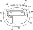
- FIG. 2 is a partially enlarged plan view showing the distal end portion of the ultrasonic endoscope shown in FIG. 1 and the vicinity thereof.
- 3 is a cross-sectional view taken along the line III-III shown in FIG. 2, and is a longitudinal sectional view obtained by cutting the distal end portion of the ultrasonic endoscope shown in FIG. 2 along a center line along its longitudinal direction.
- 4 is a sectional view taken along the line IV-IV shown in FIG.
- FIG. 4 is simplified for the sake of explanation, and the connection part (64: see FIG. 3) of the coaxial cable (56: see FIG. 3) and the wiring part (62: see FIG. 3) is omitted. ing.
- the distal end portion 40 of the ultrasonic endoscope 12 has an ultrasonic observation unit 36 for acquiring an ultrasonic image on the distal end side, and an endoscopic image on the proximal end side.
- an exterior member 41 made of a hard member.
- the treatment instrument outlet 44 is provided between the ultrasonic observation unit 36 and the endoscope observation unit 38, but the present invention is not particularly limited to the illustrated example, and the endoscope It may be provided in the observation unit 38 or may be provided on the base end side (curving unit 42 side) from the endoscope observation unit 38.
- the ultrasonic observation unit 36 is wired to the ultrasonic transducer unit 46, the exterior member 41 that attaches and holds the ultrasonic transducer unit 46, and the ultrasonic transducer unit 46.
- the ultrasonic transducer unit 46 is provided on the ultrasonic transducer array 50 including a plurality of ultrasonic transducers (transducers) 48, and on the end side in the width direction of the ultrasonic transducer array 50.
- a flexible printed circuit board (hereinafter simply referred to as FPC (Flexible Printed Circuit)) 60, a heat conductive layer 68 provided on the surface of the FPC 60 facing the backing material layer 54, and an exterior member 41. And a filler layer 80 that fills between the backing material layer 54. Further, the FPC 60 is wired with the other ends of the plurality of coaxial cables 56 whose one ends are electrically connected to the ultrasonic processor device 14.
- a plurality of coaxial cables 56 connected to the wiring portion 62 of the FPC 60 are bundled using the outer skin 58 on the proximal end side (universal cord 26 side) of the distal end portion 40 of the insertion portion 22.
- each coaxial cable 56 is pulled out and electrically connected to the FPC 60.
- the plurality of coaxial cables 56 include signal lines 56 a that are electrically connected to the plurality of connection portions 64 of the wiring portion 62 of the FPC 60 on the center side, and are provided on the outer layer of the signal lines 56 a.
- the signal line 56 a of the coaxial cable 56 can be wired with the wiring portion 62.
- the grounding in the present invention is not limited to zeroing the potential of the conductive member, but for example, connecting the conductive member to a member having a large electric capacity to maintain the conductive member at a constant low voltage. This includes cases where
- the coaxial cable 56 is used.
- the signal line for electrically connecting to the plurality of ultrasonic transducers 48 to transmit and receive the voltage signal and the vibration of the plurality of ultrasonic transducers 48 are used.
- a cable having a configuration different from that of the coaxial cable 56 may be used as long as it is a cable (shield cable) having a shield member that can be grounded and is electrically connected to the child ground 52b.
- the shielded cable includes a plurality of signal wires covered with an insulating outer sheath and a plurality of conductors that can be grounded on the center side, and includes a sheath covering the plurality of signal wires and the conductive wires.
- a cable having a known structure such as a cable unit can be used.
- the arrangement of the signal lines and the conductors of the cable unit is not limited to the above, and the plurality of signal lines and the conductors may be randomly arranged in the outer skin that covers them.
- the ultrasonic transducer unit 46 further includes an acoustic matching layer 76 stacked on the ultrasonic transducer array 50 and an acoustic lens 78 stacked on the acoustic matching layer 76. That is, the ultrasonic transducer unit 46 includes a laminate 47 of the acoustic lens 78, the acoustic matching layer 76, the ultrasonic transducer array 50, and the backing material layer 54.
- the acoustic matching layer 76 is for achieving acoustic impedance matching between a subject such as a human body and the ultrasonic transducer 48.
- the acoustic lens 78 attached on the acoustic matching layer 76 is for converging the ultrasonic waves emitted from the ultrasonic transducer array 50 toward the observation target site.
- the acoustic lens 78 is made of, for example, silicon resin (millable silicon rubber (HTV rubber), liquid silicone rubber (RTV rubber), etc.), butadiene resin, polyurethane resin, or the like.
- the acoustic lens 78 is made of titanium oxide, alumina, silica, or the like as necessary. The powder is mixed.
- the ultrasonic transducer array 50 of the ultrasonic transducer unit 46 includes a plurality of, for example, 48 to 192 rectangular parallelepiped ultrasonic transducers (transducers) 48 to 192 arranged in a convex arc shape toward the outside. It is an array of channels (CH). That is, the ultrasonic transducer array 50 is formed by arranging a plurality of ultrasonic transducers 48 as an example at a predetermined pitch in a one-dimensional array as shown in the drawing.
- CH channels
- the ultrasonic transducers 48 constituting the ultrasonic transducer array 50 are arranged at regular intervals in a convex curve along the axial direction of the distal end portion 40 (longitudinal axis direction of the insertion portion 22). These are sequentially driven based on a drive signal inputted from the ultrasonic processor unit 14. Therefore, convex electronic scanning is performed using the range in which the ultrasonic transducers 48 shown in FIG. 2 are arranged as the scanning range.
- the ultrasonic transducer array 50 has a width direction of the ultrasonic transducer array 50 perpendicular to the AZ direction, that is, an ultrasonic transducer, rather than a direction (AZ (azimuth) direction) parallel to the bottom surface of the backing material layer 54.
- the length of 48 in the longitudinal direction (EL (elevation) direction) is shorter, and the rear end side is inclined and disposed.
- the ultrasonic transducer 48 has a configuration in which electrodes are formed on both sides of a piezoelectric thick film such as PZT (lead zirconate titanate) or PVDF (polyvinylidene fluoride).
- One electrode is an individual electrode 52 a that is individually independent for each ultrasonic transducer 48, and the other electrode is a transducer ground (vibrator ground electrode) 52 b that is a common electrode common to all the ultrasonic transducers 48. It has become.
- the plurality of individual electrodes 52 a are disposed on the lower surface of the end portion of the plurality of ultrasonic transducers 48, and the transducer ground 52 b is provided on the upper surface of the end portion of the ultrasonic transducer 48. Yes.
- the plurality of individual electrodes 52 a and the vibrator ground 52 b constitute an electrode unit 52.
- a gap between two adjacent ultrasonic transducers 48 is filled with a filler such as an epoxy resin.
- the ultrasonic transducer unit 46 of the ultrasonic observation unit 36 when each ultrasonic transducer 48 of the ultrasonic transducer array 50 is driven and voltage is applied to both electrodes of the ultrasonic transducer 48, the piezoelectric body is The ultrasonic waves are sequentially generated by vibration, and the ultrasonic waves are irradiated toward the observation target portion of the subject. Then, by sequentially driving a plurality of ultrasonic transducers 48 with an electronic switch such as a multiplexer, the scanning range along the curved surface on which the ultrasonic transducer array 50 is arranged, for example, about several tens mm from the center of curvature of the curved surface. In range, ultrasound is scanned.
- the piezoelectric body vibrates to generate a voltage, and an electrical signal (ultrasonic detection signal) corresponding to the received ultrasound echo.
- the ultrasonic image is displayed on the monitor 20 as an ultrasonic image.
- the drive voltage is applied to the plurality of ultrasonic transducers 48, and the piezoelectric bodies constituting the plurality of ultrasonic transducers 48 vibrate to generate ultrasonic waves to be transmitted toward the object.
- the ultrasonic waves transmitted from the plurality of ultrasonic transducers 48 are reflected by the object, and the ultrasonic transducers 48 receive the ultrasonic echoes to vibrate the piezoelectric body.
- the voltage signal is generated, heat is generated in each piezoelectric body constituting the plurality of ultrasonic transducers 48.
- drive signals voltage signals
- the heat generated in the piezoelectric body increases.
- the heat dissipation structure which is a feature of the present invention, at the distal end portion 40 of the ultrasonic endoscope 12, the heat generated in the piezoelectric body can be efficiently dissipated and the accuracy of ultrasonic diagnosis is improved. be able to.
- the electrode unit 52 of the ultrasonic transducer unit 46 is ultrasonic vibration that is perpendicular to the arcuate surface due to the arrangement of a plurality (48 to 192) of ultrasonic transducers 48.
- a plurality of (48 to 192) individual electrodes 52a are provided in an arc shape on the end face side (of each ultrasonic transducer 48) of the child array 50, and are respectively conducted to the plurality (48 to 192) of ultrasonic transducers 48.
- the electrode unit 52 includes transducer grounds 52b of the plurality of ultrasonic transducers 48.
- vertical is not limited to 90 degrees, but includes substantially vertical, for example, 90 degrees ⁇ 5 degrees, that is, an angle in the range of 85 degrees to 95 degrees.
- the electrode unit 52 is provided on the end face side of the ultrasonic transducer array 50 that is perpendicular to the arrangement plane of the ultrasonic transducers 48.
- the number of the ultrasonic transducers 48 is small, It may be on the end face side. Since it is preferable that the number of the ultrasonic transducers 48 is large, it is preferable that the plurality of individual electrodes 52 a be provided on both outer side surfaces of the ultrasonic transducer array 50. A plurality of individual electrodes 52a may be provided not on the end face side of the ultrasonic transducer array 50 but on the center side.
- the ultrasonic transducers 48 are provided in multiple rows, for example, by providing two rows of ultrasonic transducers 48 in the width direction, a plurality of individual electrodes 52 a are provided on the center side of the ultrasonic transducer array 50. Even if the number of channels is large, wiring can be performed efficiently. In this manner, by adding the plurality of individual electrodes 52a to the outer side surfaces of the ultrasonic transducer array 50 and providing them on the center side, the number of ultrasonic transducers 48, that is, the number of channels can be increased.
- the plurality of individual electrodes 52 a are configured by the individual electrodes 52 a provided on the end face side in the longitudinal direction of each ultrasonic transducer 48, but the present invention is not limited to this, Even if the ultrasonic transducer array 50 is provided on any one of the outer side surface, both outer side surfaces, and the center side, the individual electrode 52a can be used as long as it is electrically connected to the individual electrode 52a of the ultrasonic transducer 48. Alternatively, another electrode wired and connected may be used.
- the electrode portion 52 includes the vibrator ground 52b directly, but may include an electrode wired and connected to the vibrator ground 52b.
- the plurality of individual electrodes 52a and the vibrator ground 52b of the electrode part 52 are preferably provided as electrode pads.
- the backing material layer 54 of the ultrasonic transducer unit 46 is inside with respect to the arrangement surface of the plurality of ultrasonic transducers 48, that is, the ultrasonic transducer array 50. It is the layer of the member which consists of a backing material arrange
- the backing material is made of a material having rigidity such as hard rubber, and an ultrasonic attenuating material (ferrite, ceramics, etc.) is added as necessary. Therefore, the ultrasonic transducer array 50 includes a plurality of rectangular transducers 48 in the illustrated example on the upper surface of the arc-shaped upper surface of the backing material layer 54 formed in a convex arc shape in cross section.
- the ultrasonic transducers 48 are arranged at equal intervals so that the longitudinal directions are parallel, that is, a plurality of ultrasonic transducers 48 are arranged in an arc shape and outward.
- the shape of the backing material layer 54 may be any shape that does not impair the above role, and may have a substantially semi-cylindrical shape as shown in FIGS. 3 and 4. A recess may be provided so as to accommodate a part.
- the filler layer 80 of the ultrasonic transducer unit 46 shown in FIGS. 3 and 4 fills the space between the exterior member 41 and the backing material layer 54, and fixes the FPC 60, the coaxial cable 56, and various wiring portions. It also has a role to play. Further, the filler layer 80 has an acoustic impedance with the backing material layer 54 so as not to reflect the ultrasonic signal propagated from the ultrasonic transducer array 50 to the backing material layer 54 side at the boundary surface with the backing material layer 54. Are preferably matched with a certain accuracy. Furthermore, in order to increase the efficiency of dissipating heat generated in the plurality of ultrasonic transducers 48, the filler layer 80 is preferably made of a member having heat dissipation properties. When the filler layer 80 has heat dissipation properties, heat is received from the backing material layer 54, the FPC 60, the coaxial cable 56, and the like, so that the heat dissipation efficiency can be improved.
- the FPC 60 of the ultrasonic transducer unit 46 has a plurality of electrode pads (not shown) electrically connected to the plurality of individual electrodes 52a of the plurality of ultrasonic transducers 48 at one end, and an ultrasonic transducer array. 50, a backing material layer 54, and the like, which are bent along the side surface in the width direction of the laminated body 47. Further, the FPC 60 is disposed on the opposite side of the backing material layer 54 from the ultrasonic transducer array 50 so as to extend beyond the backing material layer 54. In addition, the portion of the FPC 60 that extends beyond the backing material layer 54 on the opposite side of the backing material layer 54 with respect to the backing material layer 54 (below the backing material layer 54) is flat without bending.
- the FPC 60 includes a wiring portion 62 including a plurality of connection portions 64 wired to the signal lines 56 a of the plurality of coaxial cables 56, and a transducer ground 52 b of the ultrasonic transducer 48 below the backing material layer 54.
- a conductive ground portion 66 that is electrically connected and grounded.
- the FPC 60 is bent and disposed so that the FPC 60 extends below the backing material layer 54, so that the space in the distal end portion 40 of the insertion portion 22 is not greatly occupied.
- Various wirings can be performed by effectively using the space in the distal end portion 40 while keeping the size of the device small.
- connection means between the individual electrode 52a of the electrode part 52 and the electrode pad of the FPC 60 can be electrically connected
- a connection means using a solder wire, a conductive paste or the like, or a well-known method such as wire bonding Electrical connection means may be used.
- the FPC 60 need not be disposed along the side surface in the width direction of the multilayer body 47 as long as it electrically connects the electrode portion 52 and the signal lines 56 a of the plurality of coaxial cables 56.
- the electrode portion 52 is provided on the center side in the width direction of the stacked body 47, one or more FPCs 60 may be embedded in the backing material layer 54, or a plurality of electrodes of the FPC 60 may be disposed.
- a pad (not shown) may be disposed so as to face the lower surface of the backing material layer 54.
- the heat conductive layer 68 of the ultrasonic transducer unit 46 is a member for conducting heat generated in the plural ultrasonic transducers 48 to the ground portion 66 of the FPC 60.
- the heat conductive layer 68 is integrally formed on one surface of the FPC 60 on the backing material layer 54 side, and along with the FPC 60, the backing material layer 54 extends along the backing material layer 54. It extends below the material layer 54. Further, the heat conductive layer 68 is thermally connected to the plurality of ultrasonic transducers 48 of the ultrasonic transducer array 50. Therefore, a heat radiation path can be provided without occupying a large space in the distal end portion 40 of the insertion portion 22.
- the heat conductive layer 68 is a metal material having high thermal conductivity such as copper, aluminum or silver, highly heat conductive ceramics, or heat in order to efficiently conduct heat generated by the plurality of ultrasonic vibrators 48. It is preferable to use a conductive silicon sheet or the like.
- a plurality of electrode portions 52 are arranged so that the heat conductive layer 68 and the plurality of individual electrodes 52a do not interfere with each other as in the example shown in FIG. It is preferable that the heat conductive layer 68 is removed at a portion where the individual electrode 52a and the FPC 60 are connected.
- the heat conductive layer 68 is preferably in contact with the plurality of ultrasonic transducers 48 in order to efficiently conduct the heat generated in the plurality of ultrasonic transducers 48. As long as the plurality of individual electrodes 52a and the heat conductive layer 68 do not interfere with each other, the heat conductive layer 68 may be formed using other configurations as appropriate.
- the heat conductive layer 68 is formed to extend to the end of the FPC 60 opposite to the ultrasonic transducer array 50 (below the backing material layer 54).
- the lower end of the layer 54 is thermally connected to a ground portion 66 disposed on the surface of the FPC 60 opposite to the heat conductive layer 68.
- the heat conductive layer 68 and the ground portion 66 are thermally connected using wiring (not shown) provided in the FPC 60, but if they can sufficiently conduct heat, You may thermally connect using well-known members, such as a solder wire or a conducting wire.
- the means for thermally connecting the heat conductive layer 68 and the ground portion 66 can sufficiently transfer heat, and the plurality of ultrasonic vibrators 48 and their connection portions are affected by heat damage or the like.
- a connection means using soldering or a silver paste it is preferable to use low melting point solder.
- the heat conductive layer 68 may be formed on the FPC 60 so as to be electrically connected to the ground portion 66 from the surface on which the heat conductive layer 68 is formed, through the inside of the FPC 60.
- connection portion 64 is less likely to interfere with the heat conductive layer 68. That is, the wiring structure between the plurality of connection portions 64 and the signal lines 56a of the plurality of coaxial cables 56 is simplified, and the wiring workability is improved.
- the heat conductive layer 68 is provided as one of the layers of the FPC 60, but may be formed using means such as coating.
- the heat conductive layer 68 is formed by being applied to the surface of the FPC 60, for example, an epoxy adhesive 122-07 manufactured by Creative Materials Co., Ltd. or a heat dissipation grease X-23-8033-1 manufactured by Shin-Etsu Silicone Co., Ltd. is used.
- the conductive layer 68 can be used. In the example shown in FIG.
- the heat conductive layer 68 is formed on the surface of the FPC 60 on the backing material layer 54 side, but if the heat generated in the plurality of ultrasonic vibrators 48 can be conducted, It may be provided on the side opposite to the backing material layer 54, or may be provided on both sides in order to improve the efficiency of heat conduction. Further, when the heat conductive layer 68 is formed on the opposite side of the backing material layer 54 of the FPC 60, the heat conductive layer 68 is formed only on the backing material layer 54 side with respect to the plurality of connecting portions 64. It is preferable to form the heat conductive layer 68 so as to prevent interference between the connection portion 64 and the heat conductive layer 68.
- the heat conductive layer 68 is formed only on one surface of the FPC 60 on the backing material layer 54 side. However, the heat generated in the plurality of ultrasonic transducers 48 is grounded 66. In other words, the FPC 60 may be disposed on the opposite surface of the backing material layer 54 or may be disposed on both surfaces. That is, the heat conductive layer 68 may be disposed so as to extend on at least one surface of the FPC 60 and below the backing material layer 54.
- the heat conductive layer 68 is integrally formed on at least one surface of the FPC 60, and the backing is formed along the side surfaces in the width direction of the plurality of ultrasonic transducers 48 and the backing material layer 54. It extends below the material layer 54. Therefore, the heat generated by the plurality of ultrasonic transducers 48 is radiated to the grounded portion in the ultrasonic endoscope 12 via the ground portion 66 of the FPC 60 while keeping the distal end portion 40 of the insertion portion 22 small. can do. Further, since the heat conductive layer 68 is formed with no gap with respect to the FPC 60, the filling failure of the filler when forming the filler layer 80 so as to fill the space between the exterior member 41 and the backing material layer 54 is prevented. can do.
- the portion where the heat conductive layer 68 is formed on at least one surface of the FPC 60 has a thickness as compared with the FPC 60 where the heat conductive layer 68 is not formed, and the heat conduction. Since the rigidity of the layer 68 is added, it is difficult to bend. Therefore, due to the configuration of the distal end portion 40 of the insertion portion 22, for example, it may be difficult to bend and arrange the FPC 60 together with the heat conductive layer 68. Therefore, for example, the FPC 60 can be easily disposed by forming the heat conductive layer 68 only in a portion excluding a portion where the FPC 60 is bent. In the example shown in FIG.
- the FPC 60 is bent and disposed so as to contact the side surfaces in the width direction of the ultrasonic transducer array 50 and the backing material layer 54.
- the heat conductive layer 70 is provided only on a portion of the FPC 60 that is on the opposite side of the backing material layer 54 and that extends below the backing material layer 54.
- the ultrasonic transducer unit 69 is thermally connected to the plurality of ultrasonic transducers 48 of the ultrasonic transducer array 50 at one end and thermally connected to the heat conductive layer 70 at the other end. 71. It is preferable that the heat conducting member 71 is not connected to the FPC 60 in a portion where the FPC 60 is bent in order not to disturb the flexibility of the FPC 60.
- the heat conducting member 71 is only connected to the plurality of ultrasonic transducers 48 and the heat conducting layer 70 at one end, and has no other connection point.
- the heat conducting member 71 and the bent portion of the FPC 60 are located apart from each other. However, as described above, the bent portion of the heat conducting member 71 and the FPC 60 must have no connection point. What is necessary is just to contact.
- the heat conducting member 71 only needs to be able to sufficiently conduct the heat generated from the plurality of ultrasonic vibrators 48 to the heat conducting layer 70, and is a metal member having a large heat conductivity such as copper, aluminum, gold, or silver. And a thermally conductive silicon sheet can be used.
- the shape of the heat conducting member 71 may be any shape that can be easily disposed, and a known shape such as a foil shape, a line shape, or a net shape can be used.
- the heat conduction member 71 has a longer length from the plurality of ultrasonic transducers 48 to the heat conduction layer 70 than the FPC 60 in view of easy arrangement.
- an ultrasonic echo signal (voltage signal). It is preferable that the heat conducting member 71 and the individual electrode 52a of the electrode part 52 are connected so as not to interfere electrically so that noise is not included in the. That is, it is preferable that the heat conducting member 71 is in contact with the plurality of ultrasonic transducers 48 in a portion excluding the plurality of individual electrodes 52a.
- the thermal connection means between the heat conducting member 71 and the plurality of ultrasonic vibrators 48 and the heat conducting layer 70 is capable of sufficiently transferring the heat from the ultrasonic vibrator 48 to the heat conducting layer 70. As long as the thermal influence on the ultrasonic transducer 48 such as damage to the plural ultrasonic transducers 48 is prevented, there is no particular limitation.
- connection means a well-known connection means that does not require a high temperature, such as a connection means using a low melting point solder or silver paste, can be used.
- a connection means using a low melting point solder or silver paste can be used.
- the heat conductive layer 70 may be formed on both sides of the FPC 60.
- the heat conductive layer 70 is formed only on the flat surface portion of the FPC 60 that extends below the backing material layer 54, and the FPC 60 is bent along the backing material layer 54.
- a heat conducting member 71 that thermally connects the ultrasonic vibrator 48 and the heat conducting layer 70 away from the bent portion of the FPC 60, the FPC 60 and the heat conducting layer 70 are disposed in the ultrasonic vibrator unit. 69 can be easily disposed.
- the thermal conduction layer 70 can be formed as the FPC 60 layer below the backing material layer 54 to reduce the gap structure of the ultrasonic transducer unit 69, the filler layer 80 can be formed. , Filling failure of the filler can be prevented.
- the heat conductive layer 70 is formed on the surface opposite to the backing material layer 54 of the FPC 60, but can also be disposed on the surface of the FPC 60 on the backing material layer 54 side.
- FIG. 7 shows another example of the ultrasonic transducer unit of the present embodiment.
- the ultrasonic transducer unit 72 is a portion where the FPC 60 extends below the backing material layer 54, and is disposed on a part of the FPC 60 opposite to the backing material layer 54 side.
- a heat conductive layer 73b disposed on the surface on the backing material layer side.
- the heat conductive layers 73a and 73b disposed on both sides of the FPC 60 are thermally connected through wirings (not shown) provided inside the FPC 60, respectively. Therefore, the heat conducted by the heat conducting member 71 from the plurality of ultrasonic transducers 48 to the heat conducting layer 73a is conducted through the wiring inside the FPC 60.
- the thermal conductive layer 73b on the backing material layer 54 side of the FPC 60 and the ground portion 66 are thermally connected through the FPC 60.
- the thermal conductive layer 73b and the ground portion 66 are sufficient.
- the thermal connection means is not particularly limited as long as it is thermally connected.
- a metal member having high thermal conductivity such as a conductive wire, solder wire or copper foil, or a heat conductive silicon sheet may be thermally connected using a well-known connection means such as soldering or silver paste.
- a metal member having high thermal conductivity such as a conductive wire, solder wire or copper foil, or a heat conductive silicon sheet may be thermally connected using a well-known connection means such as soldering or silver paste.
- the drawing is simplified for the sake of explanation, and the coaxial cable 56 (see FIGS. 3 and 5), the wiring portion 62 (see FIG. 3), and the connection portion. 64 (see FIG. 3) is omitted.
- the heat conductive layers 73a and 73b are disposed on both sides of the FPC 60 only in the portion of the FPC 60 that extends below the backing material layer 54, and the heat conductive layers 73a and 73b are , And thermally connected through the FPC 60. Therefore, the FPC 60 and the heat conductive layers 73a and 73b can be easily disposed on the ultrasonic transducer unit 72, and the plurality of connection portions 64 of the wiring portion 62 and the signal line 56a of the coaxial cable 56 can be wired. It becomes easy and workability at the time of wiring improves.
- the plurality of connection portions 64 of the wiring portion 62 of the FPC 60 are electrically connected to the plurality of individual electrodes 52a of the electrode portion 52 that are electrically connected to the plurality of ultrasonic transducers 48 via wiring (not shown) provided inside the FPC 60. Are connected to the signal lines 56 a of the plurality of coaxial cables 56.
- the plurality of connection portions 64 are disposed on the same surface as the ground portion 66 of the FPC 60 and closer to the backing material layer 54 than the ground portion 66.
- the place where the plurality of connection portions 64 are disposed is not particularly limited, and may be appropriately disposed at any place in order to improve workability in wiring.
- the total number of the plurality of connection portions 64 is preferably at least the same as the number of channels of the ultrasonic transducer array 50. Therefore, the plurality of connection portions 64 may be arranged in multiple rows on the FPC 60 as necessary.
- the ground portion 66 of the FPC 60 is a conductive electrode that is electrically connected to the vibrator ground 52 b of the electrode portion 52 via a wiring (not shown) in the FPC 60.
- the shield layers 56c of the plurality of coaxial cables 56 are electrically connected. Therefore, the shield layers 56c of the plurality of coaxial cables 56 electrically connected to the ground portion 66 can have the same ground potential.
- the ground portion 66 is thermally connected to the heat conductive layer 68 disposed on one surface of the FPC 60. In this way, by thermally connecting the heat conductive layer 68 and the ground portion 66, the heat generated by the plurality of ultrasonic transducers 48 can be dissipated using a simple structure.
- the ground portion 66 is the lower end portion of the backing material layer 54 of the FPC 60, and is on the side opposite to the backing material layer 54 of the FPC 60.
- the position of the insertion portion 22 may be appropriately changed depending on the configuration of the distal end portion 40 or the configuration of the wiring.
- the ground portion 66 may be disposed on the backing material layer 54 side, which is a portion extending to the surface on the backing material layer 54 side of the FPC 60 and the lower side of the backing material layer 54.
- the ground portion 66 is composed of the plurality of ultrasonic transducers 48.
- the heat from the heat is conducted to a member having a larger heat capacity than the heat conductive layer 68 and the ground portion 66, so that a heat dissipation effect is obtained.
- the heat conductive layer 68 includes ultrasonic echo signals (voltage signals) of the plurality of ultrasonic transducers 48. ), The ultrasonic echo signal can be made free from external noise.
- the heat conductive layer 68 when the heat conductive layer 68 is formed on the same surface as the wiring part 62 of the FPC 60, a plurality of signal lines 56 a are wired with a plurality of connection parts 64. Since the coaxial cable 56 and the wiring of the heat conductive layer 68 and the ground portion 66 are on the same plane, the wiring is complicated. Therefore, the wiring structure can be simplified by disposing the heat conductive layer 68 on the surface of the FPC 60 so that the plurality of connection portions 64 do not interfere with the heat conductive layer 68 and the ground portion 66. In the example illustrated in FIG.
- the ground portion 66 of the FPC 60 is disposed on one end side of the FPC 60, and the plurality of connection portions 64 are disposed adjacent to the ground portion 66.
- the heat conductive layer 74 disposed on the same surface of the FPC 60 as the wiring part 62 is thermally connected to the ground part 66 so as to surround the plurality of connection parts 64 except for the plurality of connection parts 64. To be formed.
- the heat conductive layer 74 and the ground portion 66 are soldered or silver paste. There is no need to connect using a connecting means using the, and the plurality of wirings in the wiring part 62 are not complicated.
- FIG. 8 is a schematic diagram simplified for explaining the configuration of the heat conductive layer 74.
- the heat conductive layer 74 is formed only on the same surface as the wiring portion 62 of the FPC 60, a plurality of heat conductive layers 74 are formed.
- the heat conductive layer 74 may be formed on the entire surface of one side of the portion excluding the connection portion 64 and extending at least below the backing material layer 54.
- the heat generated from the plurality of ultrasonic transducers 48 constituting the ultrasonic transducer array 50 is The heat can be transmitted to the heat conductive layers 68, 70, 73 a, 73 b or 74 and further radiated to the grounded portion in the ultrasonic endoscope 12 such as the shield layer 56 c of the coaxial cable 56 via the ground portion 66.
- the heat conductive layers 68, 70, 73a, 73b or 74 are formed so as not to interfere with the plurality of connection portions 64 of the wiring portion 62 connected to the signal lines 56a of the plurality of coaxial cables 56, they are externally provided. The received noise can be prevented from being included in the ultrasonic echo. Furthermore, all of the heat dissipation structures described above are simple structures, and do not occupy a large space in the distal end portion 40 of the ultrasonic endoscope 12. Therefore, heat can be efficiently radiated while the size of the distal end portion 40 of the insertion portion 22 is kept small. In the present embodiment, the heat dissipation structure of the convex ultrasonic endoscope 12 has been described. However, the above heat dissipation structure does not depend on the shape of the ultrasonic endoscope, and other shapes such as a radial type. Of course, the present invention can also be applied to an ultrasonic endoscope having
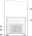
- the endoscope observation unit 38 includes an observation window 82, an objective lens 84, a solid-state imaging device 86, an illumination window 88, a cleaning nozzle 90, a wiring cable 92 including a plurality of coaxial cables (not shown), and the like. .
- the observation window 82 is attached obliquely above the tip portion 40.
- the reflected light of the observation target part incident from the observation window 82 is imaged on the imaging surface of the solid-state imaging device 86 by the objective lens 84.
- the solid-state image sensor 86 photoelectrically converts the reflected light of the site to be observed that has passed through the observation window 82 and the objective lens 84 and is imaged on the imaging surface, and outputs an imaging signal.
- Examples of the solid-state imaging device 86 include a CCD (Charge Coupled Device) and a CMOS (Complementary Metal Oxide Semiconductor).
- the captured image signal output from the solid-state imaging device 86 is transmitted to the endoscope processor device 16 by the universal code 26 via the wiring cable 92 extending from the insertion unit 22 to the operation unit 24.
- the endoscope processor device 16 performs various signal processing and image processing on the transmitted imaging signal, and displays the signal on the monitor 20 as an endoscope optical image.
- the illumination windows 88 are provided on both sides of the observation window 82.
- An emission end of a light guide (not shown) is connected to the illumination window 88.
- the light guide extends from the insertion portion 22 to the operation portion 24, and an incident end thereof is connected to the light source device 18 connected via the universal cord 26.
- Illumination light emitted from the light source device 18 travels through the light guide and is irradiated from the illumination window 88 to the site to be observed.
- the cleaning nozzle 90 cleans the surfaces of the observation window 82 and the illumination window 88 from the water supply tank 21a through the air / water supply pipe line in the ultrasonic endoscope 12 to the air or the cleaning water. 82, and jetted toward the illumination window 88.
- the distal end portion 40 is provided with a treatment instrument outlet 44.
- the treatment instrument outlet 44 is connected to a treatment instrument channel 45 inserted into the insertion portion 22, and the treatment instrument inserted into the treatment instrument insertion slot 30 is connected to the treatment instrument outlet 45 via the treatment instrument channel 45. 44 is introduced into the body cavity.
- the treatment instrument outlet 44 is located between the ultrasonic observation unit 36 and the endoscope observation unit 38, the movement of the treatment instrument introduced into the body cavity from the treatment instrument outlet 44 is detected by ultrasonic waves. In the case of a configuration for confirming with an image, it is preferable to dispose it close to the ultrasonic observation unit 36.
- an upright for changing the direction in which the treatment tool introduced from the treatment tool outlet 44 into the body cavity may be provided inside the treatment tool outlet 44.
- a wire (not shown) is attached to the stand, and the rising angle of the stand is changed by using a push-pull operation by means of an operation of the stand lever (not shown) of the operation unit 24 as a means. Is derived in the desired direction.
- the insertion unit 22 When observing the inside of a body cavity using the ultrasonic endoscope 12, first, the insertion unit 22 is inserted into the body cavity, and an endoscope optical image acquired by the endoscope observation unit 38 is observed on the monitor 20. While searching for a site to be observed. Next, when the distal end portion 40 reaches the site to be observed and an instruction to acquire an ultrasonic tomographic image is given, a plurality of coaxial cables 56 provided in the ultrasonic endoscope 12 from the ultrasonic processor device 14, A drive control signal is input to the ultrasonic transducer 48 via the FPC 60 and the electrode unit 52. When the drive control signal is input, a prescribed voltage is applied to both electrodes of the ultrasonic transducer 48.
- the piezoelectric body of the ultrasonic vibrator 48 is excited, and ultrasonic waves are emitted to the site to be observed via the acoustic lens 78.
- an echo signal from the observation target part is received by the ultrasonic transducer 48.
- the irradiation of the ultrasonic wave and the reception of the echo signal are repeatedly performed while the driving ultrasonic transducer 48 is shifted by an electronic switch such as a multiplexer. Thereby, an ultrasonic wave is scanned to an observation object site
- an ultrasonic tomographic image is generated based on the detection signal received from the ultrasonic transducer 48 by receiving the echo signal.
- the generated ultrasonic tomographic image is displayed on the monitor 20.
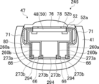
- FIG. 9 shows a partial cross-sectional view of the ultrasonic transducer unit of the ultrasonic observation unit in the second embodiment of the present invention.
- FIG. 9 is simplified for the sake of explanation in the same manner as FIGS. 4, 6, and 7 of the first embodiment, and a plurality of connection portions (not shown) and a plurality of wiring portions 62 are provided.
- a plurality of coaxial cables (not shown) wired to the connection portion are omitted.
- the ultrasonic transducer unit 246 of the second embodiment shown in FIG. 9 is compared with the ultrasonic transducer unit 69 of the first embodiment shown in FIG.
- An FPC 260a having heat conductive layers 273a and 273b that are further thermally connected to the heat conductive member 71 that is thermally connected to the plurality of ultrasonic transducers 48, and a heat conductive layer 273b between the pair of FPCs 260a and 260a.
- the ultrasonic transducer unit 246 includes a pair of FPCs (outer FPCs) 260 a and 260 a disposed on the outermost side with respect to the center side of the backing material layer 54, and a pair of FPCs 260 a and 260 a.
- FPCs (inner FPCs) 260b, 260b and four FPCs 260a, 260a, 260b, 260b that are thermally connected to each other are provided.
- a heat conductive layer 273a is formed on the surface (outer surface) opposite to the backing material layer 54 of the FPC 260a.
- the conductive layer 273 a and the plurality of ultrasonic transducers 48 are thermally connected via a heat conductive member (first heat conductive member) 71. Further, a heat conductive layer 273b is formed on the surface (inner side surface) of the plurality of FPCs 260a and 260b on the backing material layer 54 side, and the heat conductive layers 273b and ground portions 66 of the adjacent FPCs 260a and 260b and 260b and 260b, respectively. Are thermally connected via the second heat conducting member 294.
- FIG. 9 is a simplified diagram for explanation, and is connected to a wiring portion (not shown) disposed in the FPCs 260a and 260b, a plurality of connection portions (not shown), and the wiring portion and the ground portion 66.
- a coaxial cable (not shown) is omitted.
- a plurality of outer FPCs 260a of the ultrasonic transducer unit 246 are electrically connected to a plurality of individual electrodes 52a of the electrode unit 52 disposed on one end side in the width direction of the ultrasonic transducer array 50 at one end,
- the plurality of ultrasonic transducers 48 and the backing material layer 54 are bent along the side surfaces, and are disposed so as to extend below the backing material layer 54.
- the outer FPC 260a extends below the backing material layer 54, in a flat planar portion, a heat conductive layer 273a formed on the outer surface, and a backing material layer 54 in the planar portion of the FPC 260a.
- a ground portion 66 provided on the outer surface of the opposite end (lower end) and electrically connected to a shield layer (not shown) of a plurality of coaxial cables (not shown), and outside of the FPC 260a.
- a wiring portion (not shown) that is provided on a side surface and includes a plurality of connection portions (not shown) that are electrically connected to signal lines (not shown) of a plurality of coaxial cables.
- an inner FPC 260b that is thermally connected to the ground portion 66 via a wiring (not shown).
- the heat conduction layer 273a is thermally connected to the plurality of ultrasonic vibrators 48 via the heat conduction member 71, the heat generated in the plurality of ultrasonic vibrators 48 is transferred to the heat conduction layer 273a. Heat is radiated to the shield layers of the plurality of coaxial cables via the connected ground portion 66.
- a pair of FPCs 260a are arranged on both side surfaces of the laminate 47 in the width direction. However, both sides of the laminate 47 in the width direction according to the number of channels of the ultrasonic transducer array 50.
- the FPC 260a may be disposed on only one of the sides.
- the heat conduction layer 273a thermally connected to the plurality of ultrasonic transducers 48 is formed on the outer surface of the FPC 260a.
- a heat conductive layer 273 b that is thermally connected to the F may be formed.
- heat conductive layers 273a and 273b that are thermally connected to the plurality of ultrasonic transducers 48 may be formed on both surfaces of the FPC 260a.
- the FPC 260 a need not be disposed along the side surface in the width direction of the multilayer body 47 as long as it is electrically connected to the plurality of individual electrodes 52 a of the electrode portion 52.
- a plurality of FPCs 260a and 260b may be disposed such that the lower side or a part of the backing material layer 54 is embedded in the backing material layer 54.
- the FPC 260b on the inner side of the ultrasonic transducer unit 246 is electrically connected to the plurality of individual electrodes 52a of the electrode portion 52 disposed on one end side in the width direction of the ultrasonic transducer array 50 at one end, similarly to the outer FPC 260a. Connected to each other, bent along the side surfaces of the plurality of ultrasonic transducers 48 and the backing material layer 54, and arranged to extend below the backing material layer 54.
- the inner FPC 260 b has the same configuration as the outer FPC 260 a except that the heat conductive layer 273 a is not formed on the outer surface, and the lower end portion of the planar portion of the FPC 260 a is the same.
- an inner FPC 260 b that is thermally connected to the ground portion 66.
- the ground portion 66 of the inner FPC 260b is thermally connected to the heat conductive layer 273b formed on the inner side surface of the adjacent outer FPC 260a via the second heat conductive member 294.
- the heat conductive layer 273b of the inner FPC 260b is thermally connected to the heat conductive layer 273b of the adjacent inner FPC 260b via the second heat conductive member 294.
- a pair of FPCs 260b are disposed on both side surfaces in the width direction of the multilayer body 47 as with the outer FPC 260a.
- the multilayer body The FPC 260a may be provided only on one of the side surfaces in the width direction 47, or the number of the FPCs 260b provided on the inside may be increased.
- the FPC 260b is not formed with the heat conductive layers 273a and 273b that are thermally connected to the plurality of ultrasonic transducers 48, but a plurality of FPCs 260b are provided on the outer surface, the inner surface, or both surfaces of the FPC 260b.
- Thermally conductive layers 273a and 273b that are thermally connected to the ultrasonic transducer 48 may be formed.
- the heat of the plurality of ultrasonic transducers 48 can be radiated to the shield layers of the plurality of coaxial cables via the ground portion 66 of the inner FPC 260b and the second heat conducting member 294.
- the outer FPC 260a is not necessarily provided with the heat conductive layer 273a or 273b that is thermally connected to the plurality of ultrasonic transducers 48.
- the inner FPC 260b is disposed along the side surface in the width direction of the multilayer body 47 as long as it is electrically connected to the plurality of individual electrodes 52a of the electrode portion 52. You don't have to.
- the heat conductive layer 273 a of the ultrasonic transducer unit 246 is formed on the outer surface of the outer FPC 260 a and extends below the backing material layer 54.
- the thermal conduction member 71 is thermally connected to one end on the 54 side and the ground portion 66 of the FPC 60 is thermally connected to the other end.
- the heat conductive layer 273b of the ultrasonic transducer unit 246 is formed on at least a part of the inner side surfaces of the FPCs 260a and 260b and extending to the inner peripheral side of the backing material layer 54. In the example shown in FIG.
- the heat conductive layers 273b and 273b of the pair of outer FPCs 260a and 260a are grounded on the opposite surface via wiring (not shown) provided in the outer FPC 260a. It is thermally connected to the portion 66. Further, the heat conductive layer 273b provided on the inner side surface of the inner FPC 260b is connected to the ground portion 66 disposed on the surface opposite to the heat conductive layer 273b of the FPC 260b via the wiring in the inner FPC 260b. Thermally connected.
- the location where the heat conductive layers 273a and 273b are formed is not limited to the example shown in FIG. 9 as long as the heat generated in the plurality of ultrasonic transducers 48 can be conducted to the ground portion 66.
- the heat conductive layer 273b formed on the inner surface of the FPC 260a and the FPC 260b is formed on the entire surface on one side, and the heat disposed on the outer surface of the FPC 260a and the FPC 260b.
- the conductive layer 273a may be formed on a part of the outer surface for thermal connection with the heat conducting member 71.
- the heat conductive layer 273a or 273b may be formed on the entire surface of one side or both sides of the plurality of FPCs 260a and 260b without providing the heat conductive member 71.
- the second heat conducting member 294 of the ultrasonic transducer unit 246 is for thermally connecting the plurality of heat conducting layers 273a and 273b respectively formed on the plurality of FPCs 260a or 260b. Therefore, heat generated in the plurality of ultrasonic transducers 48 can be radiated without shortage to the shield layers of all the coaxial cables connected to the plurality of FPCs 260a and 260b via the respective ground portions 66.
- the second heat conductive member 294 is preferably a material having high heat conductivity, such as metal such as copper, brass, aluminum, gold and silver, heat conductive silicon, or high heat conductive ceramics. be able to.
- the shape of the second heat conducting member 294 is not particularly limited as long as it does not hinder heat conduction, and the ground portion 66 and the heat conducting layer of the FPC 260a or 260b such as a linear shape, a foil shape, a net shape, or a pin. A shape that can be easily connected to 273b can be used as appropriate.
- the second heat conducting member 294 since the second heat conducting member 294 only needs to be able to thermally connect the ground portions 66 of the plurality of FPCs 260a and 260b, the ground portions 66 of the plurality of FPCs 260a and 260b do not pass through the heat conducting layer 273b. They can also be connected thermally.
- the ground portions 66 of the FPCs 260a and 260b shown in FIG. 9 are shielded from a plurality of coaxial cables (not shown) in the same manner as the ground portions 66 of the first embodiment shown in FIG. 3, FIG. 4, and FIGS.
- the ground portion 66 is provided on the outer surface of the FPCs 260a and 260b.
- the ground portion 66 is thermally connected to the heat conductive layer 273a or 273b and the shield layers of a plurality of coaxial cables.
- the FPCs 260a and 260b may be provided on the inner surface.
- the arrangement of the ground portion 66 is not particularly limited to the location shown in FIG. 9 as long as it is provided in the FPCs 260a and 260b.
- the ground portions 66 of the adjacent FPCs 260a and 260b can be thermally connected to each other. Therefore, the heat generated in the plurality of ultrasonic transducers 48 is shielded from the plurality of coaxial cables via the heat conducting member 71, the heat conducting layers 273a and 273b, the second heat conducting member 294, and the ground portion 66. It is possible to radiate heat without any shortage to the member.
- the heat dissipation structure of the convex ultrasonic endoscope has been described in the present embodiment, but the above heat dissipation structure does not depend on the shape of the ultrasonic endoscope.
- the present invention can also be applied to an ultrasonic endoscope having another shape such as a radial type.
- FIG. 10 is a partially enlarged plan view showing the distal end portion of the insertion portion of the ultrasonic endoscope of the present embodiment.
- FIG. 11 is a cross-sectional view taken along line XI-XI shown in FIG. 10, and is a partial longitudinal sectional view of the distal end portion of the insertion portion of the ultrasonic endoscope shown in FIG.
- FIG. 12 is a schematic partial longitudinal sectional view of the distal end portion of the insertion portion of the ultrasonic endoscope shown in FIGS. 10 and 11.
- an ultrasonic transducer in which a plurality of ultrasonic transducers 348 are arranged in a cylindrical shape.
- a radial type ultrasonic endoscope having an ultrasonic transducer unit 346 including an array 350.
- the ultrasonic observation unit 336 is disposed closer to the distal end side of the ultrasonic endoscope 312 than the endoscope observation unit 338.
- the ultrasonic endoscope 312 of the present invention is a mechanism for deriving treatment tools such as forceps, a puncture needle, and a high-frequency knife as in the case of the ultrasonic endoscope 12 according to the first embodiment shown in FIGS. It may be provided.
- treatment instrument outlets (not shown) through which these treatment instruments are derived may be located closer to the distal end side of the ultrasonic endoscope 312 than the plurality of ultrasonic transducers 348, or closer to the proximal end side. May be.
- the endoscope observation unit 338 of the ultrasonic endoscope 312 of the present embodiment is the same as the endoscope observation unit 38 of the ultrasonic endoscope 12 of the first embodiment shown in FIGS. It has a configuration, and has an observation window (82), an objective lens (84), a solid-state image sensor (86), an illumination window (88), a cleaning nozzle (90), a wiring cable (92), and the like. Of course.
- the ultrasonic observation unit 336 of the present embodiment includes an ultrasonic transducer unit 346, an exterior member 341 that attaches and holds the ultrasonic transducer unit 346, and the ultrasonic transducer unit. And a plurality of coaxial cables 56 wired to 346.
- the ultrasonic transducer unit 346 includes an ultrasonic transducer array 350 in which a plurality of ultrasonic transducers 348 are arranged in a cylindrical shape, and an electrode unit 352 that is electrically connected to the ultrasonic transducer array 350.
- the ultrasonic transducer unit 346 includes the multilayer body 347 including the acoustic lens 378, the acoustic matching layer 376, the ultrasonic transducer array 350, and the backing material layer 354. Note that the ultrasonic transducer 348, the ultrasonic transducer array 350, the electrode unit 352, the backing material layer 354, the acoustic matching layer 376, the acoustic lens 378, and the laminate 347 of this embodiment are shown in FIGS.
- the configuration thereof is different. Since the functions are the same, the description thereof is omitted.
- the ultrasonic transducer unit 346 is disposed so as to contact the surface of the acoustic matching layer 376 opposite to the acoustic lens 378, the side surface in the width direction of the ultrasonic transducer array 350, and the backing material layer 354.
- the FPC 360 electrically connected to the electrode portion 352, the heat conduction layer 368 provided on the surface of the FPC 360 on the backing material layer 354 side, and the side opposite to the distal end side of the ultrasonic endoscope 312 (ultrasonic endoscope)
- a side surface in the width direction on the base end side of the mirror 312 is an annular plate member disposed so as to contact the side surface in the width direction of the backing material layer 354 on the distal end side of the ultrasonic endoscope 312;
- An annular plate 300 for fixing the position of a cylindrical member 304, which will be described later, and a backing material layer 354 of the annular plate 300 are joined to the opposite surface, and a disk-like shape having an outer diameter larger than the inner diameter of the annular plate 300.
- Support plate 3 which is a plate material 2 and the surface of the backing material layer 354 on the opposite side of the ultrasonic transducer array 350 (inside the backing material layer 354), and the end surface on the distal end side of the ultrasonic endoscope 312 is in contact with the support plate 302.
- the electrode unit 352 of the ultrasonic transducer unit 346 includes an individual electrode 352a for transmitting and receiving a voltage signal such as a drive signal and an ultrasonic echo signal to each of the plurality of ultrasonic transducers 348, and a plurality of ultrasonic transducers 348. And a vibrator ground 352b which is a ground electrode.
- the individual electrode 352a is disposed inside the ultrasonic transducer 348 and at the proximal end of the ultrasonic endoscope 312 and includes a plurality of electrode pads (not shown) of the FPC 360. ) And electrically connected.
- the transducer ground 352b is disposed outside the ultrasonic transducer 348 and at the proximal end of the ultrasonic endoscope 312, and is an electrode pad of the FPC 360 that is electrically connected to the individual electrode 352a. Is electrically connected to another electrode pad.
- the plurality of electrode pads electrically connected to the plurality of individual electrodes 352a are electrically connected to the signal lines 56a of the plurality of coaxial cables 56, and the electrode pads electrically connected to the transducer ground 352b are coaxial. It is electrically connected to the shield layer 56c of the cable 56. Therefore, the individual electrode 352a is electrically connected to the signal line 56a of the coaxial cable 56, and the vibrator ground 352b is electrically connected to the shield layer 56c of the coaxial cable 56.
- the transducer ground 352b is a ground electrode for the plurality of ultrasonic transducers 348, the ground potential is preferably the same potential. Therefore, the transducer ground 352b is a common electrode for the plurality of ultrasonic transducers 348. It is preferable. Furthermore, the vibrator ground 352b only needs to be electrically connected to the grounded portion, and does not necessarily have to pass through the electrode pad (not shown) of the FPC 360, and is electrically connected to the shield layers 56c of the plurality of coaxial cables 56. You don't have to. For example, the vibrator ground 352b and the ground portion 366 can be electrically connected using a conductive wire provided in addition to the FPC 360.
- the positions at which the plurality of individual electrodes 352a and the transducer ground 352b are disposed can be connected to the signal line 56a of the coaxial cable 56 and the grounding portion provided in the ultrasonic endoscope 312 as shown in FIG. It is not limited to the position shown in. That is, the ultrasonic transducer 348 may be disposed on the distal end side of the ultrasonic endoscope 312, and is disposed so as to cover the entire inner surface or outer surface of the ultrasonic transducer 348. Or may be appropriately changed according to the configuration of the ultrasonic observation unit 336.
- the FPC 360 of the ultrasonic transducer unit 346 has a base end side of the ultrasonic endoscope 312 with respect to the ultrasonic transducer array 350, the backing material layer 354, and the backing material layer 354 (hereinafter simply referred to as the base end side of the backing material layer 354).
- the plurality of individual electrodes 352a and the vibrator ground 352b are electrically connected to the plurality of coaxial cables 56. It is.
- the FPC 360 includes a plurality of electrode pads (not shown) electrically connected to the plurality of individual electrodes 352a of the electrode portion 352 and the vibrator ground 352b disposed on one end side, and a backing material layer 354.
- a wiring portion 362 composed of a plurality of connection portions 364 that are a plurality of terminals electrically connected to the signal lines 56a of the plurality of coaxial cables 56 disposed on the base end side, and disposed on the other end side And a ground portion 366 which is a conductive member electrically connected to the shield layer 56c of the plurality of coaxial cables 56.
- the FPC 360 is used for wiring with the electrode portion 352, it is not necessary to provide a relay point electrically connected to the electrode portion 352 in order to improve workability during wiring. The work efficiency can be improved and the wiring structure can be made simpler.
- a plurality of FPCs 360 may be provided to electrically connect all the individual electrodes 352a of the electrode portions 352 arranged in a ring shape and the signal lines 56a of the plurality of coaxial cables 56 via the FPC 360.
- the base end side portion of the backing material layer 354 of the FPC 360 may have a flat planar shape.
- the FPC 360 has a certain thickness, but it is only a schematic for explanation and is not an actual dimensional ratio.
- the thermal conduction layer 368 of the ultrasonic transducer unit is formed on the surface of the FPC 360 on the backing material layer 354 side, as in the first embodiment shown in FIG. Is transmitted to the ground portion 366 of the FPC 360.
- the heat conductive layer 368 interferes with a plurality of individual electrodes 352 a of the electrode part 352, for example, by forming the heat conductive layer 368 closer to the center of the ultrasonic transducer unit 346 than the electrode part 352. It is preferable that it is arrange
- the ultrasonic transducer unit 346 of the present embodiment shown in FIG. 11 can transfer the heat generated in the plurality of ultrasonic transducers 348 to the ground portion as in the example of the first embodiment shown in FIG. Heat can be radiated to the shield layers 56c of the plurality of coaxial cables 56 that are electrically connected to the ground portion 366 via the 366.
- the heat conductive layer 368 is disposed on the surface of the FPC 360 on the backing material layer 354 side, but may be capable of conducting heat generated from the plurality of ultrasonic transducers 348. For example, it may be formed on the opposite surface of the backing material layer 354 of the FPC 360, or may be formed on both surfaces.
- the FPC 360 has a heat conduction layer at a portion where the ultrasonic transducer 348, the backing material layer 354, and the cylindrical member 304 on the proximal end side of the backing material layer 354 are bent. 368 is formed. Therefore, the combined thickness of the FPC 360 and the heat conduction layer 368 increases, and the rigidity of the heat conduction layer 368 is added to the FPC 360. Therefore, workability when the FPC 360 and the heat conduction layer 368 are disposed in the ultrasonic transducer unit 346 is improved. Is a factor that decreases.
- FIG. 12 as in the example of the first embodiment shown in FIG.
- the FPC 360 is not bent, that is, in a portion extending beyond the backing material layer 354. Only the heat conductive layer 370 is formed.
- the ultrasonic transducer unit 369 includes a heat conductive member (first member) that is thermally connected to the heat conductive layer 370 at one end and thermally connected to the plurality of ultrasonic vibrators 348 at the other end.
- the heat conductive member 371 is made of a metal member having a high thermal conductivity such as copper, aluminum, gold, or silver, or heat conductive silicon, similar to the heat conductive member 71 of the first embodiment shown in FIG. Furthermore, in order to improve workability at the time of arrangement, a flexible shape such as a conductive wire shape, a foil shape, or a mesh shape can be used. Therefore, similarly to the first embodiment shown in FIG. 6, the heat generated in the plurality of ultrasonic vibrators 348 is transferred to the ground portion 366 and the simple structure using the simple configuration while improving the workability during the arrangement. Heat can be radiated to the shield layers 56 c of the plurality of coaxial cables 56. Note that FIG.
- the heat conductive layer 370 is formed on the same surface as the wiring part 362 of the FPC 360 as in the example shown in FIG. 12, for example, as in the example of the first embodiment shown in FIG. It is preferable to insulate the heat conductive layer 370 and the wiring part 362 by arranging the layer 370 so as to surround the wiring part 362.
- the heat conductive layer 370 is formed on the surface opposite to the backing material layer 354 of the FPC 360, but the heat generated in the plurality of ultrasonic transducers 348 is generated. If the ultrasonic transducer unit 369 includes the heat conducting member 371, the heat conducting member 371 may be disposed on the backing material layer 354 side of the FPC 360 as long as it can conduct. In FIG. 13, similarly to the first embodiment shown in FIG. 7, in the plane portion where the FPC 360 of the ultrasonic transducer unit 372 extends beyond the backing material layer 354, the heat conductive layers 373a and 373b are formed on both sides of the FPC 360. Is formed.
- a heat conductive layer 373a is formed on the flat surface portion of the FPC 360, on the surface opposite to the backing material layer 354 and on the end portion on the heat conductive layer 370 side, and the entire surface on the surface on the backing material layer 354 side is heated.
- a conductive layer 373b is formed.
- the heat conductive layers 373a and 373b are thermally connected to each other via a wiring (not shown) provided inside the FPC 360. Further, the thermal conductive layer 373b and the ground portion 366 of the FPC 360 are thermally connected via the FPC 360, similarly to the other example of the ultrasonic transducer unit 369 of the present embodiment shown in FIG.
- the heat generated in the plurality of ultrasonic transducer units 346 can be radiated to the ground portion 366 and the shield layers 56c of the plurality of coaxial cables 56 via the heat conduction member 371, the heat conduction layers 373a and 373b, and the FPC 360. it can.
- the heat conductive layer 373 a is provided only at the end portion on the heat conductive member 371 side, but can be formed to extend to the ground portion 366. In this case, since the heat dissipation path to the ground portion 366 can be widened, the total heat conduction efficiency in the heat conductive layers 373a and 373b can be improved, that is, the heat dissipation efficiency can be improved. .
- FIG. 13 is simplified for the sake of explanation, as in FIG. 12, and is electrically connected to a wiring portion 362 provided on the same surface as the ground portion 366 of the FPC 360 and a plurality of connection portions 364 of the wiring portion 362.
- the signal line 56a of the coaxial cable 56 connected to is omitted.
- the support plate 302 of the ultrasonic transducer unit 346 is disposed in contact with the surface opposite to the backing material layer 354 of the annular plate 300, and has an outer diameter larger than the inner diameter of the annular plate 300. It is a disk-shaped plate material having a diameter.
- the support plate 302 is for fixing the positions of the annular plate 300 and the cylindrical member 304. Therefore, the support plate 302 is preferably joined to the cylindrical member 304 in order to fix the position where the cylindrical member 304 is disposed. Therefore, the support plate 302 may be a member integrated with the cylindrical member 304.
- the support plate 302 when the support plate 302 is bonded to the cylindrical member 304, it is preferable that the support plate 302 is also bonded to the annular plate 300 in order to fix the position of the cylindrical member 304.
- the support plate 302 is not limited to a disk shape as long as the positions of the annular plate 300 and the cylindrical member 304 can be fixed, and may be an arbitrary shape such as a polygonal shape.
- the cylindrical member 304 of the ultrasonic transducer unit 346 is in contact with the inner surface of the backing material layer 354, the inner surface of the annular plate 300, and the surface of the support plate 302 opposite to the distal end side of the ultrasonic endoscope. And the laminated body 347 is fixed.
- a plurality of coaxial cables 56 covered with an outer skin 58 are disposed in the space of the cylindrical member 304 on the center side of the ultrasonic transducer unit 346 (inside the cylindrical member 304).
- a plurality of slits 306 for leading out the plurality of coaxial cables 56 to the outer peripheral side of the cylindrical member 304 are provided in the proximal end portion of the backing material layer 354 of the cylindrical member 304.
- the cylindrical member 304 may be any member that can support the laminated body 347 and may be configured using any member such as metal or resin.
- a plurality of electrode pads are provided at the end of the FPC 360 on the ultrasonic transducer array 350 side.
- the plurality of electrode pads of the FPC 360 are a plurality of electrodes that are electrically connected to the plurality of individual electrodes 352 a and the vibrator ground 352 b of the electrode portion 352.
- those that are electrically connected to the plurality of individual electrodes 352a are electrically connected to the plurality of connection portions 364 of the wiring portion 362 via wiring (not shown) provided in the FPC 360.
- What is electrically connected to the vibrator ground 352b is electrically connected to the ground portion 366 via another wiring (not shown) provided in the FPC 360. Therefore, the total number of the plurality of electrode pads of the FPC 360 is preferably equal to or greater than at least the total number of the plurality of ultrasonic transducers 348 (the number of channels of the ultrasonic transducer array 350).
- the wiring portion 362 of the FPC 360 includes a plurality of connection portions 364 that are terminals respectively wired to the signal lines 56a of the plurality of coaxial cables 56.
- the sound wave oscillator unit 346 is disposed on the front end side.
- the total number of the plurality of connection portions 364 constituting the wiring portion 362 is preferably at least equal to or greater than the total number of the plurality of electrode pads (not shown) of the FPC 360. Further, when the number of channels of the ultrasonic transducer array 350 is large, which causes a reduction in workability during wiring, the ultrasonic transducer array 350 may be arranged in multiple rows.
- the wiring portion between the signal lines of the plurality of coaxial cables 56 and the plurality of connection portions 364 is covered with a filler (not shown) such as an insulating resin in order to prevent disconnection in the wiring portion. It is preferable.
- the ground portion 366 of the FPC 360 is a conductive member that is electrically connected to the plurality of electrode pads of the FPC 360 that are electrically connected to the vibrator ground 352 b of the electrode portion 352 and is electrically connected to the shield layers 56 c of the plurality of coaxial cables 56. . Therefore, the shield layers 56c of the plurality of coaxial cables 56 are grounded, and the heat conductive layers 368 (see FIG. 11), 370 (see FIG. 12), 373a (see FIG. 13), and 373b (see FIG. 13). ) And the heat conduction member 371 (FIG.
- the vibrator ground 352b can be grounded. Therefore, in addition to grounding the transducer ground 352b, external noise can be prevented from being included in the ultrasound echo signals (voltage signals) received by the plurality of ultrasound transducers 348.
- a plurality of ultrasonic waves can be obtained using a simple configuration.
- Heat generated in the vibrator 348 can be conducted to the ground portion 366 provided in the FPC 360.
- the ground portion 366 is electrically connected to the shield layers 56 c of the plurality of coaxial cables 56, the heat conducted to the ground portions 366 is radiated to the shield layers 56 c of the plurality of coaxial cables 56. Therefore, heat generated in the plurality of ultrasonic transducers 348 can be efficiently radiated using a simple configuration.
- the heat conductive layers 370 see FIG.
- 348 can be thermally connected using a heat conducting member 371 to facilitate disposition of the heat dissipation structure.
- the ultrasonic endoscope having the heat dissipation structure according to the present invention has been described in detail above, but the present invention is not limited to the above examples, and various improvements and modifications can be made without departing from the gist of the present invention. Of course, you may also do.
- the embodiment and the plurality of examples described above can be used in combination as appropriate.
Abstract
超音波内視鏡は、複数の超音波振動子が配列した超音波振動子アレイと、超音波振動子を支持するバッキング材層と、信号線と信号線に対するシールド部材とを備えるシールドケーブルと、バッキング材層に対し超音波振動子アレイの逆側に延在し、シールド部材と電気的に接続されたグランド部を備えるフレキシブルプリント配線基板と、フレキシブルプリント配線基板の少なくとも一方の面に設けられ、グランド部と接続され、複数の超音波振動子の発熱をグランド部に放熱する熱伝導層とを有する。
Description
本発明は、超音波内視鏡に係り、特に、体腔内に挿入される超音波内視鏡に用いられる超小型超音波振動子において発生した熱を放熱するための構造を先端部に有する超音波内視鏡に関する。
超音波内視鏡は、経消化管による胆嚢、又は膵臓の観察を主な目的として、内視鏡の先端部に超音波観察部を設けたものである。超音波内視鏡の先端部においては、超音波振動子及び内視鏡の光源などの発熱要因があるが、超音波内視鏡の先端部は、人体などの生体の内部に直接接触するものであるため、低温火傷を防止するなどの安全上の理由から、挿入部の表面温度が一定の温度以下であることが要請されている。
更に、超音波内視鏡の先端部には、超音波観察部の他に、超音波観察部を設けていない通常の内視鏡と同様に、照明部及び吸引口などが設けられている。そのため、超音波内視鏡の先端部の外径は太くなり、超音波内視鏡の操作性の低下及び超音波内視鏡の先端部が挿入される患者の負担が増加する要因となっている。
そこで、先端部を小型に維持しつつ、先端部の表面温度を低下させるための手段を有する超音波内視鏡が求められている。そのため、近年では、超音波振動子において発生した熱を放熱するための様々な提案がなされている(特許文献1及び2参照)。
特許文献1は、屈曲部を有する挿入部を備え、その挿入部において、複数の超音波振動子が配置された前面を有するバッキング材層と、挿入部の先端において複数の超音波振動子を収容する外装部材と、外装部材内に配設されて、バッキング材層の裏面及び外装部材の内面に接する熱伝導部材を有する超音波内視鏡を開示している。この構成によれば、超音波振動子において生じてバッキング材層に伝導した熱、及びバッキング材層で生じた熱は、バッキング材層を介して熱伝導部材に伝導し、更に、熱伝導部材を介して外装部材に伝導して、外装部材から超音波内視鏡の外部へ放熱される。
特許文献2は、超音波を発振する圧電素子と、圧電素子と電気的に接続され、圧電素子の背面に設けられた信号用電極と、圧電素子を機械的に支えるためのバッキング材層と、信号用電極とバッキング材層との間に配設された熱伝導部材と、熱伝導部材と当接するようにバッキング材層の周辺に設けられた放熱材と、を有する超音波探触子を開示している。この構成によれば、圧電素子で発生した熱は、熱伝導部材を経由して放熱材に放熱される。
ところで、特許文献1に開示の技術では、超音波振動子及びバッキング材層において発生した熱を、熱伝導部材を介して外装部材に放熱する放熱パスのみが考慮されている。このように、特許文献1に開示の技術では、いずれも外装部材への放熱パスしか考慮されていないため、更なる放熱効果の向上が望めないという問題があった。更に特許文献1に開示の技術では、外装部材への放熱パスのみであるために、超音波内視鏡の先端部付近の体腔内に放熱することとなり、超音波振動子の駆動電圧を上昇させていった場合に、超音波内視鏡の先端部の周囲の温度を上昇させてしまうという問題があった。
また、特許文献2に開示の技術では、生体に接触させて超音波観察をする超音波診断装置の超音波探触子を主としているため、熱伝導部材及び放熱板などのサイズが大きい。そのため、圧電素子と熱伝導部材との接触する面積が大きく、放熱性を確保することができるが、先端部内の空間が狭い超音波内視鏡においては、十分な放熱性を確保することが困難であるという問題があった。
また、特許文献1又は2に開示の超音波内視鏡又は超音波探触子において、超音波診断の診断精度を向上させるには、例えば、超音波振動子を積層化して超音波の送信出力を増加させる、超音波振動子の配設数を増加して超音波エコーに対する受信感度を高める、及び、複数の超音波振動子の駆動電圧を増大させるなどの手段を用いる必要がある。そのような手段を用いた場合には、複数の超音波振動子からの放熱量が増大するため、患者の体腔内壁と接する超音波内視鏡の挿入部、特に複数の超音波振動子が配設される超音波内視鏡の先端部表面の温度が上昇する要因となる。
操作性の向上及び患者負担の改善に加えて、超音波診断における精度の向上が求められているにも関わらず、超音波振動子の挿入部を小径に、かつ先端部を小型に維持しつつ、超音波内視鏡の先端部において発生した熱を効率よく放熱することは、非常に難しいという問題があった。
操作性の向上及び患者負担の改善に加えて、超音波診断における精度の向上が求められているにも関わらず、超音波振動子の挿入部を小径に、かつ先端部を小型に維持しつつ、超音波内視鏡の先端部において発生した熱を効率よく放熱することは、非常に難しいという問題があった。
本発明は、上記従来技術の問題点を解消し、挿入部を小径に、かつ先端部を小型に維持しつつ、超音波振動子において発生した熱を効率的に放熱することができる放熱構造を有し、その結果、超音波診断における診断精度を向上させることができる超音波内視鏡を提供することを目的とする。
上記目的を達成するために、本発明の超音波内視鏡は、複数の超音波振動子が配列された超音波振動子アレイと、複数の超音波振動子を支持するバッキング材層と、バッキング材層に対して超音波振動子アレイとは逆側に延在し、超音波振動子アレイの複数の超音波振動子とそれぞれ電気的に接続された複数の電極パッドを備えるフレキシブルプリント配線基板と、複数の超音波振動子にそれぞれ電気的に接続される信号線を備え、複数の信号線に対するシールド部材を備える複数のシールドケーブルと、複数のシールドケーブルの複数の信号線がそれぞれフレキシブルプリント配線基板の複数の電極パッドと電気的に接続されている複数の接続部を備える配線部と、フレキシブルプリント配線基板上に設けられ、シールドケーブルのシールド部材と電気的に接続されたグランド部と、フレキシブルプリント配線基板の少なくとも一方の面に設けられ、グランド部と接続され、複数の超音波振動子の発熱をグランド部に放熱する熱伝導層と、を有することを特徴とする。
更に、熱伝導層は、フレキシブルプリント配線基板の、バッキング材層に対して超音波振動子アレイとは逆側に、バッキング材層を越えて延在する部分に少なくとも設けられることが好ましい。
更に、フレキシブルプリント配線基板の、バッキング材層に対して超音波振動子アレイとは逆側に、バッキング材層を超えて延在する部分は、平面部分であることが好ましい。
また、熱伝導層は、フレキシブルプリント配線基板の少なくとも1面に、超音波振動子アレイの複数の超音波振動子に熱的に接続され、超音波振動子アレイから、バッキング材層に沿って、バッキング材層を越えて、バッキング材層に対して超音波振動子アレイとは逆側に延在して設けられ、グランド部と接続されることが好ましい。
もしくは、熱伝導層は、フレキシブルプリント配線基板の少なくとも1面に、バッキング材層に対して超音波振動子アレイとは逆側に、バッキング材層を越えて延在する部分に設けられ、更に、超音波振動子アレイの複数の超音波振動子と、熱伝導層とを熱的に接続する熱伝導部材を有することが好ましい。
更に、熱伝導層は、フレキシブルプリント配線基板のバッキング材層を越えて延在する部分の、バッキング材層とは逆側の片面のみに設けられ、熱伝導部材は、フレキシブルプリント配線基板のバッキング材層とは逆側の片面において複数の超音波振動子と、熱伝導層とを熱的に接続することが好ましい。
更に、熱伝導層は、フレキシブルプリント配線基板の両面に設けられ、熱伝導部材は、フレキシブルプリント配線基板のバッキング材層とは逆側の片面において、複数の超音波振動子と、同じ側の片面に設けられた熱伝導層とを熱的に接続し、フレキシブルプリント配線基板の両面に設けられた2つの熱伝導層は互いに熱的に接続されていることが好ましい。
また、フレキシブルプリント配線基板の配線部と同じ側の面に設けられた熱伝導層は、配線部の複数の接続部を除いて、複数の接続部を囲うように配設されることが好ましい。
また、バッキング材層に対して超音波振動子アレイの逆側において、複数のフレキシブルプリント配線基板が配設されることが好ましい。
更に、本発明の超音波内視鏡は、複数のフレキシブルプリント配線基板にそれぞれ設けられた複数の熱伝導層を互いに接続する第2の熱伝導部材を有することが好ましい。
本発明によれば、超音波内視鏡の先端部分に放熱構造を設けることで、超音波振動子の駆動により発生する熱を効率的に放熱することができ、超音波内視鏡の被検体である患者の負担を増加させることなく、超音波振動子の出力を高くすることができる。
(第1の実施形態)
本発明に係る超音波内視鏡を添付図面に示す好適実施形態に基づいて以下に詳細に説明する。
図1は、本発明の超音波内視鏡を使用する超音波検査システムの構成の一例を示す概略構成図である。
図1に示す超音波検査システム10は、患者などの被検体の体表からの超音波検査では困難な胆嚢又は膵臓の観察を、被検体の体腔である食道、胃、十二指腸、小腸、及び大腸などの消化管を経由して可能にし、超音波断層画像(以下、超音波画像という)を取得する超音波観察部36と、内視鏡光学画像(以下、内視鏡画像という)を取得する内視鏡観察部38とを有する本発明の超音波内視鏡12を被検体の体腔内に挿入して、被検体の内視鏡画像を観察しながら被検体の観察対象部位の超音波画像を取得するものである。
図1に示すように、超音波検査システム10は、本発明の特徴である放熱構造を有する超音波内視鏡12と、超音波画像を生成する超音波用プロセッサ装置14と、内視鏡画像を生成する内視鏡用プロセッサ装置16と、体腔内を照明する照明光を超音波内視鏡12に供給する光源装置18と、超音波画像及び/又は内視鏡画像を表示するモニタ20と、を備えて構成されている。
また、超音波検査システム10は、更に、洗浄水などを貯留する送水タンク21aと、体腔内の吸引物(供給された洗浄水なども含む)を吸引する吸引ポンプ21bとを備えている。なお、超音波検査システム10は、図示しないが、更に、送水タンク21a内の洗浄水、又は外部の空気などの気体を超音波内視鏡12内の管路(図示せず)に供給する供給ポンプなどを備えていても良い。
また、超音波検査システム10は、更に、洗浄水などを貯留する送水タンク21aと、体腔内の吸引物(供給された洗浄水なども含む)を吸引する吸引ポンプ21bとを備えている。なお、超音波検査システム10は、図示しないが、更に、送水タンク21a内の洗浄水、又は外部の空気などの気体を超音波内視鏡12内の管路(図示せず)に供給する供給ポンプなどを備えていても良い。
まず、図1に示す超音波内視鏡12は、本発明の特徴である放熱構造を有する超音波観察部36と内視鏡観察部38とを先端に有し、被検体の体腔内を撮影して、それぞれ超音波画像(エコー信号)及び内視鏡画像(画像信号)を取得するものである。
超音波内視鏡12は、先端に超音波観察部36と内視鏡観察部38とを備え、被検体の体腔内に挿入される挿入部22と、挿入部22の基端部に連設され、医師や技師などの術者が操作を行うための操作部24と、操作部24に一端が接続されたユニバーサルコード26とから構成されている。
超音波内視鏡12は、先端に超音波観察部36と内視鏡観察部38とを備え、被検体の体腔内に挿入される挿入部22と、挿入部22の基端部に連設され、医師や技師などの術者が操作を行うための操作部24と、操作部24に一端が接続されたユニバーサルコード26とから構成されている。
操作部24には、送水タンク21aから送気送水管路(図示せず)を開閉する送気送水ボタン28a、及び吸引ポンプ21bからの吸引管路(図示せず)を開閉する吸引ボタン28bが並設されると共に、一対のアングルノブ29、29、及び処置具挿入口(鉗子口)30が設けられている。
ここで、送水タンク21aは、超音波内視鏡12の内視鏡観察部38などの洗浄などのために超音波内視鏡12内の送気送水管路に供給する洗浄水などを貯留するためのものである。なお、送気送水ボタン28aは、送水タンク21aから送気送水管路を経て供給された空気などの気体、及び洗浄水などの水を挿入部22の先端側の内視鏡観察部38から噴出させるために用いられる。
ここで、送水タンク21aは、超音波内視鏡12の内視鏡観察部38などの洗浄などのために超音波内視鏡12内の送気送水管路に供給する洗浄水などを貯留するためのものである。なお、送気送水ボタン28aは、送水タンク21aから送気送水管路を経て供給された空気などの気体、及び洗浄水などの水を挿入部22の先端側の内視鏡観察部38から噴出させるために用いられる。
また、吸引ポンプ21bは、超音波内視鏡12の先端側から体腔内の吸引物(供給された洗浄水なども含む)を吸引するために吸引管路(図示せず)を吸引するものである。吸引ボタン28bは、吸引ポンプ21bの吸引力を用いて挿入部22の先端側から体腔内の吸引物を吸引するために用いられる。
また、処置具挿入口30は、鉗子や穿刺針、高周波メスなどの処置具を挿通するためのものである。
また、処置具挿入口30は、鉗子や穿刺針、高周波メスなどの処置具を挿通するためのものである。
ユニバーサルコード26の他端部には、超音波用プロセッサ装置14に接続される超音波用コネクタ32aと、内視鏡用プロセッサ装置16に接続される内視鏡用コネクタ32bと、光源装置18に接続される光源用コネクタ32cとが設けられている。超音波内視鏡12は、これらの各コネクタ32a、32b、及び32cを介してそれぞれ超音波用プロセッサ装置14、内視鏡用プロセッサ装置16、及び光源装置18に着脱自在に接続される。また、光源用コネクタ32cには、送水タンク21aを接続する送気送水用チューブ34a、及び吸引ポンプ21bを接続する吸引用チューブ34bなどが接続される。
挿入部22は、先端側から順に、硬質部材で形成され、超音波観察部36と内視鏡観察部38とを有する先端部(先端硬質部)40と、先端部40の基端側に連設され、複数の湾曲駒を連結してなり、湾曲自在の湾曲部42と、湾曲部42の基端側と操作部24の先端側との間を連結し、細長かつ長尺の可撓性を有する軟性部43とから構成されている。
湾曲部42は、操作部24に設けられた一対のアングルノブ29、29を回動されて遠隔的に湾曲操作される。そのため、先端部40を所望の方向に向けることができる。
湾曲部42は、操作部24に設けられた一対のアングルノブ29、29を回動されて遠隔的に湾曲操作される。そのため、先端部40を所望の方向に向けることができる。
また、先端部40には、内部に、超音波観察部36を覆う超音波伝達媒体(例えば、水、オイルなど)を注入したバルーンが着脱自在に装着されていても良い。超音波及びエコー信号は空気中で著しく減衰するため、このバルーンに超音波伝達媒体を注入して膨張させ、観察対象部位に当接させることにより、超音波観察部36の超音波振動子(超音波トランスデューサ)アレイ(50:図2~図4、図6及び図7参照)と観察対象部位の間から空気を排除し、超音波及びエコー信号の減衰を防止することができる。
なお、超音波用プロセッサ装置14は、超音波内視鏡12の挿入部22の先端部40の超音波観察部36の超音波振動子ユニット(46:図2~図4参照、69:図6参照、72:図7参照)の超音波振動子アレイ(50:図2~図4、図6及び図7参照)に超音波を発生させるための超音波信号(データ)を生成して供給するものである。また、超音波用プロセッサ装置14は、超音波が放射された観察対象部位から反射されたエコー信号(データ)を超音波振動子アレイ(50)において受信して取得し、取得したエコー信号に対して各種の信号(データ)処理を施してモニタ20に表示される超音波画像を生成するためのものである。
内視鏡用プロセッサ装置16は、超音波内視鏡12の挿入部22の先端部40の内視鏡観察部38において光源装置18からの照明光に照明された観察対象部位から取得された撮像画像信号(データ)を受信して取得し、取得した画像信号に対して各種の信号(データ)処理、及び画像処理を施して、モニタ20に表示される内視鏡画像を生成するためのものである。
なお、これらのプロセッサ装置14、及び16は、PC(パーソナルコンピュータ)などのプロセッサを用いて構成されるものであっても良い。
なお、これらのプロセッサ装置14、及び16は、PC(パーソナルコンピュータ)などのプロセッサを用いて構成されるものであっても良い。
光源装置18は、超音波内視鏡12の内視鏡観察部38を用いて体腔内の観察対象部位を撮像して画像信号を取得するために、赤光(R)、緑光(G)、及び青光(B)などの3原色光からなる白色光や特定波長光などの照明光を、発生させて、超音波内視鏡12に供給し、超音波内視鏡12内のライトガイド(図示せず)などを伝搬し、超音波内視鏡12の挿入部22の先端部40の内視鏡観察部38から出射して、体腔内の観察対象部位を照明するためのものである。
モニタ20は、超音波用プロセッサ装置14及び内視鏡用プロセッサ装置16により生成された各映像信号を受けて超音波画像や内視鏡画像を表示する。これらの超音波画像や内視鏡画像の表示は、いずれか一方のみの画像を適宜切り替えてモニタ20に表示することや両方の画像を同時に表示することなどが可能である。なお、超音波画像を表示するためのモニタと内視鏡画像を表するためのモニタを別個に設けてよいし、他の任意の形態において、これらの超音波画像と内視鏡画像とを表示するようにしてもよい。
次に、本実施形態の超音波内視鏡12の挿入部22の先端部40の構成を図2~図4を参照して詳細に説明する。
図2は、図1に示す超音波内視鏡の先端部及びその近傍を示す部分拡大平面図である。図3は、図2に示すIII-III線矢視図であり、図2に示す超音波内視鏡の先端部をその長手方向に沿った中心線で切断した縦断面図である。図4は、図3に示すIV-IV線矢視図であり、図3に示す超音波内視鏡の先端部の超音波観察部の超音波振動子アレイの円弧構造の中心線で切断した横断面図である。ここで、図4は、説明のために図を簡略化しており、同軸ケーブル(56:図3参照)及び配線部(62:図3参照)の接続部(64:図3参照)を省略している。
図2は、図1に示す超音波内視鏡の先端部及びその近傍を示す部分拡大平面図である。図3は、図2に示すIII-III線矢視図であり、図2に示す超音波内視鏡の先端部をその長手方向に沿った中心線で切断した縦断面図である。図4は、図3に示すIV-IV線矢視図であり、図3に示す超音波内視鏡の先端部の超音波観察部の超音波振動子アレイの円弧構造の中心線で切断した横断面図である。ここで、図4は、説明のために図を簡略化しており、同軸ケーブル(56:図3参照)及び配線部(62:図3参照)の接続部(64:図3参照)を省略している。
図2、及び図3に示すように、超音波内視鏡12の先端部40には、先端側に超音波画像を取得するための超音波観察部36と、基端側に内視鏡画像を取得するための内視鏡観察部38と、これらの間に処置具導出口44とが設けられており、共に超音波内視鏡12の先端部40の先端部本体となる、硬質樹脂などの硬質部材からなる外装部材41に取り付けられて保持されている。
図2に示す例では、処置具導出口44は、超音波観察部36と内視鏡観察部38との間に設けられているが、本発明は特に図示例に限定されず、内視鏡観察部38内に設けられていても良いし、内視鏡観察部38よりも基端側(湾曲部42側)に設けられていても良い。
図2に示す例では、処置具導出口44は、超音波観察部36と内視鏡観察部38との間に設けられているが、本発明は特に図示例に限定されず、内視鏡観察部38内に設けられていても良いし、内視鏡観察部38よりも基端側(湾曲部42側)に設けられていても良い。
図2~図4に示すように、超音波観察部36は、超音波振動子ユニット46と、超音波振動子ユニット46を取り付けて保持する外装部材41と、超音波振動子ユニット46に配線される複数の同軸ケーブル56と、から構成されるものである。
図4に示す一例において、超音波振動子ユニット46は、複数の超音波振動子(トランスデューサ)48からなる超音波振動子アレイ50と、超音波振動子アレイ50の幅方向の端部側に設けられる電極部52と、超音波振動子アレイ50の各超音波振動子48を下面側から支持するバッキング材層54と、バッキング材層54の幅方向の側面に沿って配設され、電極部52と電気的に接続されるフレキシブルプリント配線基板(以下、単にFPC(Flexible Printed Circuit)という)60と、FPC60の、バッキング材層54と対向する面に設けられた熱伝導層68と、外装部材41とバッキング材層54との間を埋める充填剤層80と、を有する。また、FPC60は、一端が超音波用プロセッサ装置14と電気的に接続する複数の同軸ケーブル56の他端が配線される。
図4に示す一例において、超音波振動子ユニット46は、複数の超音波振動子(トランスデューサ)48からなる超音波振動子アレイ50と、超音波振動子アレイ50の幅方向の端部側に設けられる電極部52と、超音波振動子アレイ50の各超音波振動子48を下面側から支持するバッキング材層54と、バッキング材層54の幅方向の側面に沿って配設され、電極部52と電気的に接続されるフレキシブルプリント配線基板(以下、単にFPC(Flexible Printed Circuit)という)60と、FPC60の、バッキング材層54と対向する面に設けられた熱伝導層68と、外装部材41とバッキング材層54との間を埋める充填剤層80と、を有する。また、FPC60は、一端が超音波用プロセッサ装置14と電気的に接続する複数の同軸ケーブル56の他端が配線される。
また、FPC60の配線部62に接続する複数の同軸ケーブル56は、図3に示すように、挿入部22の先端部40の基端側(ユニバーサルコード26側)において、外皮58を用いて一束に纏められており、配線の際には、各同軸ケーブル56が引き出されて、FPC60に電気的に接続される。図5に示すように、複数の同軸ケーブル56は、FPC60の配線部62の複数の接続部64と電気的に接続する信号線56aを中心側に備え、信号線56aの外側の層に設けられた絶縁性の外皮56bと、その外皮56bの外側の層に設けられ、超音波内視鏡12の基端側(ユニバーサルコード26側)において接地可能な導電性のシールド層56cと、最も外側の層に設けられた絶縁性の外皮56dと、を有するものである。そのため、図3に示す一例のように、FPC60において、グランド部66よりもバッキング材層54側に配線部62が配設されている場合において、複数の同軸ケーブル56を屈曲させないように、複数の同軸ケーブル56の信号線56aを、配線部62と配線することができる。
ここで、本発明における接地とは、導電性の部材の電位をゼロにすることに限らず、例えば、電気容量の大きい部材に接続するなどして、導電性の部材を一定の低い電圧に維持する場合も含む。
ここで、本発明における接地とは、導電性の部材の電位をゼロにすることに限らず、例えば、電気容量の大きい部材に接続するなどして、導電性の部材を一定の低い電圧に維持する場合も含む。
なお、図3に示す一例では、同軸ケーブル56を用いたが、複数の超音波振動子48に電気的に接続して電圧信号を送受信するための信号線及び複数の超音波振動子48の振動子グランド52bに電気的に接続する、接地可能なシールド部材を有するケーブル(シールドケーブル)であれば、上記の同軸ケーブル56とは異なる構成を有するケーブルを用いて良い。例えば、図示しないが、シールドケーブルとしては、絶縁性の外皮に被覆された複数の信号線と、接地可能な複数の導線と、を中心側に備え、複数の信号線及び導線を被覆する外皮を有するケーブルユニットなどの周知の構造を有するケーブルを用いることができる。なお、ケーブルユニットの信号線及び導線の配置は、上記のものに限定されず、複数の信号線及び導線は、それらを被覆する外側の外皮内においてランダムに配置されても良い。
また、超音波振動子ユニット46は、更に、超音波振動子アレイ50の上に積層された音響整合層76と、音響整合層76上に積層された音響レンズ78とを有する。すなわち、超音波振動子ユニット46は、音響レンズ78、音響整合層76、超音波振動子アレイ50、及びバッキング材層54の積層体47からなる。
音響整合層76は、人体などの被検体と超音波振動子48との間の音響インピーダンス整合をとるためのものである。
音響整合層76上に取り付けられている音響レンズ78は、超音波振動子アレイ50から発せられる超音波を観察対象部位に向けて収束させるためのものである。音響レンズ78は、例えば、シリコン系樹脂(ミラブル型シリコンゴム(HTVゴム)、液状シリコンゴム(RTVゴム)など)、ブタジエン系樹脂、ポリウレタン系樹脂などからなる。音響整合層76において被検体と超音波振動子48との間の音響インピーダンス整合をとり、超音波の透過率を高めるため、音響レンズ78には、必要に応じて酸化チタンやアルミナ、シリカなどの粉末が混合される。
超音波振動子ユニット46の超音波振動子アレイ50は、外側に向けて凸円弧状に配列された複数、例えば48~192個の直方体形状の超音波振動子(トランスデューサ)48からなる48~192チャンネル(CH)のアレイである。
すなわち、超音波振動子アレイ50は、複数の超音波振動子48が、一例として、図示例のように一次元アレイ状に予め定められたピッチで配列されてなるものである。このように、超音波振動子アレイ50を構成する各超音波振動子48は、先端部40の軸線方向(挿入部22の長手軸方向)に沿って凸湾曲状に等間隔で配列されており、超音波用プロセッサ装置14から入力される駆動信号に基づいて順次駆動されるようになっている。そのため、図2に示す超音波振動子48が配列された範囲を走査範囲としてコンベックス電子走査が行われる。
すなわち、超音波振動子アレイ50は、複数の超音波振動子48が、一例として、図示例のように一次元アレイ状に予め定められたピッチで配列されてなるものである。このように、超音波振動子アレイ50を構成する各超音波振動子48は、先端部40の軸線方向(挿入部22の長手軸方向)に沿って凸湾曲状に等間隔で配列されており、超音波用プロセッサ装置14から入力される駆動信号に基づいて順次駆動されるようになっている。そのため、図2に示す超音波振動子48が配列された範囲を走査範囲としてコンベックス電子走査が行われる。
更に、超音波振動子アレイ50は、バッキング材層54の底面と平行な方向(AZ(アジマス)方向)よりも、AZ方向と直交する超音波振動子アレイ50の幅方向、すなわち超音波振動子48の長手方向(EL(エレベーション)方向)の長さのほうが短く、後端側が張り出すように傾斜して配置される。図4に示すように、超音波振動子48は、例えば、PZT(チタン酸ジルコン酸鉛)や、PVDF(ポリフッ化ビニリデン)などの圧電体厚膜の両面に電極を形成した構成を有する。一方の電極は、超音波振動子48毎に個々に独立した個別電極52a、他方の電極は、超音波振動子48の全てに共通の共通電極である振動子グランド(振動子接地電極)52bとなっている。図示例では、複数の個別電極52aは、複数の超音波振動子48の端部の下面に配設されており、振動子グランド52bは、超音波振動子48の端部の上面に設けられている。これらの複数の個別電極52a、及び振動子グランド52bは、電極部52を構成している。
なお、隣接する2つの超音波振動子48同士の隙間には、エポキシ樹脂などの充填剤が充填されている。
なお、隣接する2つの超音波振動子48同士の隙間には、エポキシ樹脂などの充填剤が充填されている。
超音波観察部36の超音波振動子ユニット46において、超音波振動子アレイ50の各超音波振動子48が駆動され、超音波振動子48の両電極に電圧が印加されると、圧電体が振動して超音波を順次発生し、被検体の観察対象部位に向けて超音波が照射される。そして、複数の超音波振動子48をマルチプレクサなどの電子スイッチで順次駆動させることで、超音波振動子アレイ50が配された曲面に沿った走査範囲、例えば曲面の曲率中心から数十mm程度の範囲で、超音波が走査される。
また、観察対象部位から反射されたエコー信号(超音波エコー)を受信すると、圧電体が振動して電圧を発生し、この電圧を受信した超音波エコーに応じた電気信号(超音波検出信号)として超音波用プロセッサ装置14に出力する。そして、超音波用プロセッサ装置14において各種の信号処理が施されてから、超音波画像としてモニタ20に表示される。
以上のように、複数の超音波振動子48へ駆動電圧が印加されて、複数の超音波振動子48をそれぞれ構成する圧電体が振動して、対象物に向けて送信する超音波を発生する際、及び、複数の超音波振動子48から送信された超音波が対象物で反射された超音波エコーを複数の超音波振動子48が受信して圧電体が振動し、超音波エコー信号(電圧信号)を発生する際に、複数の超音波振動子48を構成するそれぞれの圧電体において熱が発生する。超音波画像を高精細化する、すなわち超音波診断の精度を向上させるための手段の1つとして、複数の超音波振動子48の駆動信号(電圧信号)の出力を増加させる手段があるが、駆動電圧が増加するほど、圧電体において発生する熱が増大する。そのため、超音波内視鏡12の先端部40に本発明の特徴である放熱構造を設けることで、圧電体において発生する熱を効率的に放熱することができ、超音波診断の精度を向上させることができる。
超音波振動子ユニット46の電極部52は、図3、及び図4に示すように、複数(48~192)の超音波振動子48の配列による円弧状面に対して垂直となる超音波振動子アレイ50の(各超音波振動子48の)端面側に円弧状に設けられるもので、複数(48~192)の超音波振動子48にそれぞれ導通する複数(48~192)の個別電極52aからなる。なお、電極部52には、複数の超音波振動子48の振動子グランド52bが含まれる。ここで、本発明において、垂直とは、90度に限定されるわけではなく、略垂直、例えば、90度±5度、すなわち、85度~95度までの範囲の角度を含むものである。
更に、電極部52は、超音波振動子48の配列面に対して垂直となる超音波振動子アレイ50の端面側に設けられるが、超音波振動子48の数が少ない場合には、片側の端面側でも良い。超音波振動子48の数は多い方が好ましいので、複数の個別電極52aは、超音波振動子アレイ50の両外側面に設けられることが好ましい。なお、複数の個別電極52aを超音波振動子アレイ50の端面側ではなく、中心側に設けても良い。例えば、超音波振動子48を幅方向に2列設けるなど、多列に超音波振動子48を設けた場合には、複数の個別電極52aを超音波振動子アレイ50の中心側に設けることにより、チャンネル数が多くても効率良く配線をすることができる。このように、複数の個別電極52aを超音波振動子アレイ50の両外側面に加え、中心側に設けることにより、超音波振動子48の数、すなわちチャンネル数をより多くすることができる。
なお、図4に示す一例では複数の個別電極52aを、各超音波振動子48の長手方向の端面側に設けられた個別電極52aで構成しているが、本発明はこれに限定されず、超音波振動子アレイ50の片外側面、両外側面、及び中心側のいずれに設けられている場合であっても、超音波振動子48の個別電極52aに導通していれば、個別電極52aと配線されて接続された別の電極を用いて構成しても良い。また、電極部52には、直接、振動子グランド52bが含まれているが、振動子グランド52bと配線されて接続された電極が含まれていても良い。また、電極部52の複数の個別電極52a及び振動子グランド52bは、電極パッドとして設けられていることが好ましい。
次に、超音波振動子ユニット46のバッキング材層54は、図3及び図4に示すように、複数の超音波振動子48の配列面に対して内側となる、すなわち超音波振動子アレイ50の背面(下面)に配設されるバッキング材からなる部材の層である。したがって、バッキング材層54は、超音波振動子アレイ50を機械的に、かつ柔軟に支持すると共に、複数の超音波振動子48から発振され、もしくは観察対象から反射して伝播した超音波信号のうち、バッキング材層54側に伝播した超音波を減衰させる役割を有する。このため、バッキング材は、硬質ゴムなどの剛性を有する材料からなり、超音波減衰材(フェライト、セラミックスなど)が必要に応じて添加されている。
したがって、超音波振動子アレイ50は、バッキング材層54の断面凸円弧状に形成された上面となる円弧状の上表面上に、図示例では、複数の直方体状の超音波振動子48をその長手方向が平行となるように、好ましくは等間隔に配列したもの、すなわち、複数の超音波振動子48が円弧状かつ外側に向けて配列されたものであることが好ましい。
なお、バッキング材層54の形状は、上記の役割を損なわないものであれば良く、図3及び図4に示すような略半円筒形状を有していても良く、FPC60及び熱伝導層68の一部を収納できるように凹部が設けられていても良い。
したがって、超音波振動子アレイ50は、バッキング材層54の断面凸円弧状に形成された上面となる円弧状の上表面上に、図示例では、複数の直方体状の超音波振動子48をその長手方向が平行となるように、好ましくは等間隔に配列したもの、すなわち、複数の超音波振動子48が円弧状かつ外側に向けて配列されたものであることが好ましい。
なお、バッキング材層54の形状は、上記の役割を損なわないものであれば良く、図3及び図4に示すような略半円筒形状を有していても良く、FPC60及び熱伝導層68の一部を収納できるように凹部が設けられていても良い。
図3及び図4に示す超音波振動子ユニット46の充填剤層80は、外装部材41とバッキング材層54との間を埋めるものであって、FPC60、同軸ケーブル56及び各種の配線部分を固定する役割も負う。また、充填剤層80は、バッキング材層54との境界面において、超音波振動子アレイ50からバッキング材層54側に伝播した超音波信号を反射しないように、バッキング材層54との音響インピーダンスが一定以上の精度で整合していることが好ましい。更に、複数の超音波振動子48において発生した熱を放熱する効率を高めるために、充填剤層80は、放熱性を有する部材で構成されていることが好ましい。充填剤層80が放熱性を有する場合には、バッキング材層54、FPC60及び同軸ケーブル56などから熱を受け取るため、放熱効率を向上することができる。
超音波振動子ユニット46のFPC60は、一端において複数の超音波振動子48の複数の個別電極52aと電気的に接続される複数の電極パッド(図示せず)を有し、超音波振動子アレイ50及びバッキング材層54などから構成される積層体47の幅方向の側面に沿って屈曲して配設される。また、FPC60は、バッキング材層54に対して超音波振動子アレイ50とは逆側に、バッキング材層54を越えて延在するように配設される。また、FPC60の、バッキング材層54に対して超音波振動子アレイ50とは逆側に、バッキング材層54を越えて延在する部分(バッキング材層54の下側)は、屈曲の無い平坦な平面部分である。更に、FPC60は、バッキング材層54の下側において、複数の同軸ケーブル56の信号線56aと配線される複数の接続部64を備える配線部62と、超音波振動子48の振動子グランド52bと電気的に接続され、接地された導電性のグランド部66と、を有する。このように、バッキング材層54の下側にFPC60が延在するように、FPC60を屈曲して配設することで、挿入部22の先端部40内の空間を大きく占有しないため、先端部40のサイズを小型に維持しつつ、先端部40内の空間を有効に使用して、各種の配線を行うことができる。
なお、電極部52の個別電極52aとFPC60の電極パッドとの接続手段は、電気的な接続ができるものであれば、半田線、導電性ペーストなどを用いる接続手段、又はワイヤボンディングなどの周知の電気的な接続手段を用いて良い。
なお、電極部52の個別電極52aとFPC60の電極パッドとの接続手段は、電気的な接続ができるものであれば、半田線、導電性ペーストなどを用いる接続手段、又はワイヤボンディングなどの周知の電気的な接続手段を用いて良い。
また、FPC60は、積層体47の幅方向の片側の側面に沿って1枚だけ配設されているが、超音波振動子アレイ50のチャンネル数(超音波振動子48の数)が多いなどの場合には、適宜配設するFPC60の数を増加させても良い。また、FPC60は、電極部52と複数の同軸ケーブル56の信号線56aとを電気的に接続させるものであれば、積層体47の幅方向の側面に沿って配設される必要はない。例えば、電極部52が積層体47の幅方向の中心側に設けられている場合などには、1以上のFPC60をバッキング材層54に埋め込んで配設しても良いし、FPC60の複数の電極パッド(図示せず)をバッキング材層54の下側面に対向するように配設してもよい。
超音波振動子ユニット46の熱伝導層68は、複数の超音波振動子48において発生した熱を、FPC60のグランド部66に伝導するための部材である。図4に示す一例において、熱伝導層68は、FPC60のバッキング材層54側の片側の面に一体的に形成され、FPC60と共に、超音波振動子アレイ50からバッキング材層54に沿って、バッキング材層54の下側に延在する。また、熱伝導層68は、超音波振動子アレイ50の複数の超音波振動子48に熱的に接続される。したがって、挿入部22の先端部40内の空間を大きく占有せずに、放熱パスを設けることができる。また、熱伝導層68は、複数の超音波振動子48で発生した熱を効率良く伝導するために、銅、アルミニウム又は銀などの熱伝導率の高い金属素材、高熱伝導性のセラミックス、又は熱伝導性のシリコンシートなどを用いることが好ましい。特に、熱伝導層68が金属素材で構成されている場合には、図4に示す一例のように、熱伝導層68と複数の個別電極52aとが干渉しないように、電極部52の複数の個別電極52aとFPC60とが接続される部分において熱伝導層68が除去されていることが好ましい。更に、熱伝導層68は、複数の超音波振動子48において発生した熱を効率良く伝導するために、複数の超音波振動子48と当接していることが好ましい。なお、複数の個別電極52aと熱伝導層68とが互いに干渉しないものであれば、適宜その他の構成を用いて熱伝導層68を形成して良い。
また、図4に示す一例において、熱伝導層68は、超音波振動子アレイ50とは逆側(バッキング材層54の下側)のFPC60の端部まで延長して形成されており、バッキング材層54の下側の端部において、熱伝導層68とは逆側のFPC60の面に配設されたグランド部66と熱的に接続される。図示例においては、熱伝導層68とグランド部66とは、FPC60内に設けられた配線(図示せず)を用いて熱的に接続されているが、十分に伝熱できるものであれば、半田線又は導線などの周知の部材を用いて熱的に接続しても良い。また、熱伝導層68とグランド部66とを熱的に接続する手段は、十分に伝熱できるもの、かつ複数の超音波振動子48及びその接続部分に対して、熱による損傷などの影響を与えるものでなければ特に制限されるものではない。例えば、半田付け又は銀ペーストを用いた接続手段などを用いることが好ましく、半田付けの場合には、低融点の半田を用いることが好ましい。また、熱伝導層68は、熱伝導層68が形成されている面から、FPC60の内部を通って、グランド部66に導通するように、FPC60に形成されても良い。このように、熱伝導層68がFPC60のバッキング材層54側の面に形成されている場合には、FPC60のバッキング材層54とは逆側の面に配設されている配線部62の複数の接続部64が熱伝導層68と干渉し難くなる。すなわち、複数の接続部64と複数の同軸ケーブル56の信号線56aとの配線構造が単純になり、配線の作業性が向上する。
なお、図4に示す一例において、熱伝導層68は、FPC60の層の1つとして設けられるが、塗布などの手段を用いて形成されるものであっても良い。FPC60の面に塗布されて熱伝導層68が形成される場合には、例えば、Creative Materials社製エポキシ接着剤122-07や信越シリコーン社製放熱用グリース X-23-8033-1などを、熱伝導層68として用いることができる。また、図4に示す一例においては、熱伝導層68は、FPC60のバッキング材層54側の面に形成されているが、複数の超音波振動子48において発生した熱を伝導できれば、FPC60の、バッキング材層54とは逆側の面に設けられていてもよく、熱伝導の効率を向上させるために、両面に設けられていても良い。また、熱伝導層68がFPC60のバッキング材層54の逆側に形成されている場合には、複数の接続部64よりもバッキング材層54側のみに熱伝導層68を形成するなど、複数の接続部64と熱伝導層68との干渉を防ぐように熱伝導層68を形成することが好ましい。
また、図4に示す一例においては、熱伝導層68は、FPC60のバッキング材層54側の片側の面にのみ形成されているが、複数の超音波振動子48において発生した熱をグランド部66に伝導できるものであれば、FPC60のバッキング材層54とは逆側の面に配設されても良いし、両面に配設されても良い。すなわち、熱伝導層68は、FPC60の少なくとも1面に、かつバッキング材層54の下側に延在するように配置されて良い。
以上に説明した構成によれば、熱伝導層68は、FPC60の少なくとも片側の面に一体的に形成され、複数の超音波振動子48及びバッキング材層54の幅方向の側面に沿って、バッキング材層54の下側に延在する。そのため、挿入部22の先端部40を小型に維持しつつ、複数の超音波振動子48で発生した熱をFPC60のグランド部66を経由して、超音波内視鏡12内の接地部位に放熱することができる。更に、熱伝導層68はFPC60に対して隙間なく形成されるため、外装部材41とバッキング材層54との間を埋めるように充填剤層80を形成する際の、充填剤の充填不良を防止することができる。
ところで、上記で説明したように、FPC60の少なくとも片側の面において熱伝導層68が形成されている部分は、熱伝導層68が形成されていないFPC60と比較して厚みを有し、かつ熱伝導層68の剛性が加わるために、屈曲し難い。そのため、挿入部22の先端部40の構成に起因して、例えば、熱伝導層68と共にFPC60を屈曲して配設することが困難である場合がある。したがって、例えば、FPC60が屈曲している部分を除く部分にのみ熱伝導層68を形成することにより、FPC60を容易に配設することができる。図6に示す一例においては、FPC60は、超音波振動子アレイ50及びバッキング材層54の幅方向の側面に当接するように沿って、屈曲して配設される。また、熱伝導層70は、FPC60の、バッキング材層54とは逆側の面であって、バッキング材層54の下側に延在する部分のみに設けられる。更に、超音波振動子ユニット69は、一端において超音波振動子アレイ50の複数の超音波振動子48と熱的に接続し、他端において熱伝導層70と熱的に接続される熱伝導部材71を有する。熱伝導部材71は、FPC60の屈曲性を妨げないために、FPC60が屈曲している部分においては、FPC60と接続していないことが好ましい。すなわち、熱伝導部材71は、複数の超音波振動子48と熱伝導層70とにそれぞれ一端で接続するのみであって、他の接続点を有さないことが好ましい。なお、図6に示す一例においては、熱伝導部材71とFPC60の屈曲部分とは離れた位置にあるが、上記のように、熱伝導部材71とFPC60の屈曲部分とが接続点を有さなければよく、接触していても良い。
なお、熱伝導部材71は、複数の超音波振動子48から発生した熱を熱伝導層70に十分に伝導することができればよく、銅、アルミニウム、金又は銀などの熱伝導率が大きい金属部材、及び熱伝導性のシリコンシートなどを用いることができる。また、熱伝導部材71の形状は、熱伝導効率に加えて、容易に配設できるものであれば良く、箔形状、線形状又はネット形状などの周知の形状を用いることができる。更に、配設の容易性から、熱伝導部材71は、FPC60よりも複数の超音波振動子48から熱伝導層70までの長さが長いことが好ましい。
また、熱伝導部材71の一端と複数の超音波振動子48との熱的な接続においては、特に熱伝導部材71が金属を用いて構成される場合には、超音波エコー信号(電圧信号)にノイズが含まれないように、熱伝導部材71と電極部52の個別電極52aとが電気的に干渉しないように接続されることが好ましい。すなわち、熱伝導部材71は、複数の個別電極52aを除く部分において、複数の超音波振動子48と当接していることが好ましい。なお、電極部52の振動子グランド52bがグランド部66又は同軸ケーブル56のシールド層56cに電気的に接続されているなど接地されている場合には、熱伝導部材71と振動子グランド52bとは、干渉していても構わない。また、熱伝導部材71と複数の超音波振動子48及び熱伝導層70との熱的な接続手段は、超音波振動子48からの熱を熱伝導層70に十分に伝熱できるものであって、複数の超音波振動子48の損傷などの、超音波振動子48に対する熱的な影響を防ぐものであれば特に制限されるものではない。このような接続手段として、低融点の半田又は銀ペーストを用いた接続手段などの、高い温度を要しない周知の接続手段を用いることができる。
また、図6に示す一例においては、バッキング材層54の下側に延在する部分において、FPC60の片側面にのみ熱伝導層70を配設する態様について説明したが、熱伝導の効率を向上させるなどのために、熱伝導層70をFPC60の両面に形成しても良い。
また、図6に示す一例においては、バッキング材層54の下側に延在する部分において、FPC60の片側面にのみ熱伝導層70を配設する態様について説明したが、熱伝導の効率を向上させるなどのために、熱伝導層70をFPC60の両面に形成しても良い。
以上において説明したように、FPC60の、バッキング材層54の下側に延在する平面部分にのみ熱伝導層70を形成して、FPC60がバッキング材層54に沿って屈曲する部分においては、複数の超音波振動子48と熱伝導層70とを熱的に接続する熱伝導部材71を、FPC60の屈曲部分と離すように配設することで、FPC60及び熱伝導層70を超音波振動子ユニット69に容易に配設することができる。また、バッキング材層54の下側において、FPC60の層として熱伝導層70を形成して、超音波振動子ユニット69の有する隙間構造を減らすことができるため、充填剤層80を形成する際の、充填剤の充填不良を防止することができる。
図6に示す一例においては、熱伝導層70は、FPC60のバッキング材層54とは逆側の面に形成されていたが、FPC60のバッキング材層54側の面にも配設することができる。図7に、本実施形態の超音波振動子ユニットの他の一例を示す。図7に示す一例においては、超音波振動子ユニット72は、FPC60がバッキング材層54の下側に延在する部分であって、FPC60の、バッキング材層54側とは逆側の一部分に配設された熱伝導層73aと、バッキング材層54側の面に配設された熱伝導層73bと、を有する。FPC60の両面に配設された熱伝導層73a及び73bはそれぞれ、FPC60の内部に設けられた配線(図示せず)を通じて熱的に接続する。そのため、熱伝導部材71が、複数の超音波振動子48から熱伝導層73aに伝導した熱は、FPC60の内部の配線を通じて伝導する。また、図7に示す一例において、FPC60のバッキング材層54側の熱伝導層73bとグランド部66とは、FPC60を通じて熱的に接続されているが、熱伝導層73bとグランド部66とが十分に熱的に接続されるものであれば、熱的な接続手段は特に制限されるものではない。例えば、導線、半田線又は銅箔などの熱伝導率の高い金属部材、又は熱伝導性のシリコンシートなどを、半田付け又は銀ペーストなどの周知の接続手段を用いて熱的に接続して良い。
なお、図6及び図7においても、図4と同様に、説明のために図を簡略化しており、同軸ケーブル56(図3及び図5参照)、配線部62(図3参照)及び接続部64(図3参照)を省略している。
なお、図6及び図7においても、図4と同様に、説明のために図を簡略化しており、同軸ケーブル56(図3及び図5参照)、配線部62(図3参照)及び接続部64(図3参照)を省略している。
以上の構成によれば、FPC60の、バッキング材層54の下側に延在する部分にのみ熱伝導層73a及び73bをFPC60の両面のそれぞれに配設して、かつ熱伝導層73a及び73bは、FPC60を介して熱的に接続される。そのため、超音波振動子ユニット72へのFPC60及び熱伝導層73a及び73bの配設が容易となることに加え、配線部62の複数の接続部64と同軸ケーブル56の信号線56aとの配線が容易になり、配線の際の作業性が向上する。
FPC60の配線部62の複数の接続部64は、FPC60の内部に設けられた配線(図示せず)を介して複数の超音波振動子48と導通する電極部52の複数の個別電極52aと電気的に接続する端子であり、複数の同軸ケーブル56の信号線56aと配線される。図4に示す一例において、複数の接続部64は、FPC60の、グランド部66と同じ面であって、グランド部66よりもバッキング材層54側に配設される。もちろん、複数の接続部64の配設される場所は、特に制限されるものではなく、配線における作業性を向上させるなどのために、適宜任意の場所に配設して良い。また、複数の接続部64の総数は、少なくとも超音波振動子アレイ50のチャンネル数と同数であることが好ましい。そのため、複数の接続部64は、必要に応じて、FPC60上に多列に配置されて良い。
図3及び図4に示す一例において、FPC60のグランド部66は、FPC60内の配線(図示せず)を介して電極部52の振動子グランド52bと電気的に接続される導電性の電極であって、複数の同軸ケーブル56のシールド層56cと電気的に接続される。そのため、グランド部66に電気的に接続した複数の同軸ケーブル56のシールド層56cは、それぞれ、接地電位を同一の電位にすることができる。更に、グランド部66は、FPC60のいずれか一方の面に配設される熱伝導層68と熱的に接続される。このように、熱伝導層68とグランド部66とを熱的に接続することにより、複数の超音波振動子48で発生した熱を、単純な構造を用いて放熱することができる。また、図3、図4、図6及び図7に示す例において、グランド部66は、FPC60のバッキング材層54の下側の端部であって、FPC60におけるバッキング材層54とは逆側の面に配設されるが、挿入部22の先端部40の構成又は配線の構成などに応じて、適宜配設する位置を変更しても良い。例えば、グランド部66は、FPC60のバッキング材層54側の面及びバッキング材層54の下側に延在する部分であってバッキング材層54側に配設されても良い。
なお、グランド部66と接続される複数の同軸ケーブル56のシールド層56cが接地されていないなど、グランド部66が接地されていない場合であっても、グランド部66が複数の超音波振動子48からの熱を、熱伝導層68及びグランド部66よりも熱容量の大きい部材に伝導することになるため、放熱効果を有する。グランド部66が接地されている場合には、特に、更に熱伝導層68が金属で構成されている場合には、熱伝導層68が複数の超音波振動子48の超音波エコー信号(電圧信号)に干渉しなくなるため、超音波エコー信号に外部からのノイズを含まないようにすることができる。
なお、グランド部66と接続される複数の同軸ケーブル56のシールド層56cが接地されていないなど、グランド部66が接地されていない場合であっても、グランド部66が複数の超音波振動子48からの熱を、熱伝導層68及びグランド部66よりも熱容量の大きい部材に伝導することになるため、放熱効果を有する。グランド部66が接地されている場合には、特に、更に熱伝導層68が金属で構成されている場合には、熱伝導層68が複数の超音波振動子48の超音波エコー信号(電圧信号)に干渉しなくなるため、超音波エコー信号に外部からのノイズを含まないようにすることができる。
ところで、例えば、図4に示す一例において、FPC60の配線部62と同じ側の面に熱伝導層68が形成された場合には、それぞれの信号線56aが複数の接続部64と配線された複数の同軸ケーブル56と、熱伝導層68とグランド部66との配線とが同じ面にあるため、配線が複雑になる。そのため、複数の接続部64と熱伝導層68及びグランド部66とが干渉しないように、FPC60の表面に熱伝導層68を配設して、配線構造を単純化することができる。図8に示す一例において、FPC60のグランド部66は、FPC60の一端側に配設され、複数の接続部64は、グランド部66に隣接して配設される。また、FPC60の、配線部62と同じ面に配設された熱伝導層74は、複数の接続部64を除いて、複数の接続部64を囲うように、かつグランド部66と熱的に接続するように形成される。このように、熱伝導層74を、複数の接続部64と干渉しないように、かつグランド部66と接続するように形成するため、熱伝導層74とグランド部66とを、半田付け又は銀ペーストを用いた接続手段を用いて接続する必要が無く、配線部62における複数の配線が複雑にならない。そのため、配線部62における配線作業の際の作業性を向上させることができ、更に、配線部62における断線の可能性を低くすることができる。
なお、図8は、熱伝導層74の構成を説明するために簡略化した模式図であり、熱伝導層74がFPC60の、配線部62と同じ面にのみ形成される場合には、複数の接続部64を除いた部分であって、少なくともバッキング材層54の下側に延在する部分の片側全面に熱伝導層74が形成されて良い。
なお、図8は、熱伝導層74の構成を説明するために簡略化した模式図であり、熱伝導層74がFPC60の、配線部62と同じ面にのみ形成される場合には、複数の接続部64を除いた部分であって、少なくともバッキング材層54の下側に延在する部分の片側全面に熱伝導層74が形成されて良い。
以上に示した本実施形態の超音波内視鏡12の挿入部22の先端部40の構成によれば、超音波振動子アレイ50を構成する複数の超音波振動子48から発生した熱を、熱伝導層68、70、73a、73b又は74に伝え、更に、グランド部66を介して同軸ケーブル56のシールド層56cなどの超音波内視鏡12内の接地部位に放熱することができる。また、熱伝導層68、70、73a、73b又は74は、複数の同軸ケーブル56の信号線56aと接続される配線部62の複数の接続部64と干渉しないように形成されるため、外部から受信するノイズを超音波エコーに含ませないようにすることができる。更に、以上で説明した放熱構造は、いずれも単純な構造であり、超音波内視鏡12の先端部40において、大きな空間を占有しない。したがって、挿入部22の先端部40のサイズを小型に維持したまま、効率よく放熱を行うことができる。また、本実施形態では、コンベックス型の超音波内視鏡12の放熱構造について説明したが、以上の放熱構造は、超音波内視鏡の形状に依るものではなく、ラジアル型などの他の形状を有する超音波内視鏡にも適用できることはもちろんである。
内視鏡観察部38は、観察窓82、対物レンズ84、固体撮像素子86、照明窓88、洗浄ノズル90、及び複数の同軸ケーブル(図示せず)などからなる配線ケーブル92などから構成される。
観察窓82は、先端部40の斜め上方に向けて取り付けられている。観察窓82から入射した観察対象部位の反射光は、対物レンズ84で固体撮像素子86の撮像面に結像される。固体撮像素子86は、観察窓82、及び対物レンズ84を透過して撮像面に結像された観察対象部位の反射光を光電変換して、撮像信号を出力する。固体撮像素子86としては、CCD(Charge Coupled Device:電荷結合素子)、及びCMOS(Complementary Metal Oxide Semiconductor:相補形金属酸化膜半導体)などを挙げることができる。固体撮像素子86で出力された撮像画像信号は、挿入部22から操作部24まで延設された配線ケーブル92を経由して、ユニバーサルコード26により内視鏡用プロセッサ装置16に伝送される。内視鏡用プロセッサ装置16は、伝送された撮像信号に対して、各種信号処理、及び画像処理を施し、内視鏡光学画像としてモニタ20に表示する。
観察窓82は、先端部40の斜め上方に向けて取り付けられている。観察窓82から入射した観察対象部位の反射光は、対物レンズ84で固体撮像素子86の撮像面に結像される。固体撮像素子86は、観察窓82、及び対物レンズ84を透過して撮像面に結像された観察対象部位の反射光を光電変換して、撮像信号を出力する。固体撮像素子86としては、CCD(Charge Coupled Device:電荷結合素子)、及びCMOS(Complementary Metal Oxide Semiconductor:相補形金属酸化膜半導体)などを挙げることができる。固体撮像素子86で出力された撮像画像信号は、挿入部22から操作部24まで延設された配線ケーブル92を経由して、ユニバーサルコード26により内視鏡用プロセッサ装置16に伝送される。内視鏡用プロセッサ装置16は、伝送された撮像信号に対して、各種信号処理、及び画像処理を施し、内視鏡光学画像としてモニタ20に表示する。
照明窓88は、観察窓82を挟んで両側に設けられている。照明窓88には、ライトガイド(図示せず)の出射端が接続されている。ライトガイドは、挿入部22から操作部24まで延設され、その入射端は、ユニバーサルコード26を介して接続された光源装置18に接続されている。光源装置18で発せられた照明光は、ライトガイドを伝って照明窓88から被観察部位に照射される。
また、洗浄ノズル90は、観察窓82、及び照明窓88の表面を洗浄するために、送水タンク21aから超音波内視鏡12内の送気送水管路を経て空気、又は洗浄水を観察窓82、及び照明窓88に向けて噴出する。
また、洗浄ノズル90は、観察窓82、及び照明窓88の表面を洗浄するために、送水タンク21aから超音波内視鏡12内の送気送水管路を経て空気、又は洗浄水を観察窓82、及び照明窓88に向けて噴出する。
また、先端部40には、処置具導出口44が設けられている。処置具導出口44は、挿入部22の内部に挿通される処置具チャンネル45に接続されており、処置具挿入口30に挿入された処置具は、処置具チャンネル45を介して処置具導出口44から体腔内に導入される。なお、処置具導出口44は、超音波観察部36と内視鏡観察部38との間に位置しているが、処置具導出口44から体腔内に導入された処置具の動きを超音波画像で確認する構成する場合には、超音波観察部36に近づけて配設することが好ましい。
処置具導出口44の内部には、図示しないが、処置具導出口44から体腔内に導入される処置具の導出方向を可変する起立台が設けられていても良い。起立台にはワイヤ(図示せず)が取り付けられており、操作部24の起立レバー(図示せず)の操作による押し引き操作を手段として用いることにより起立台の起立角度が変化し、処置具が所望の方向に導出されるようになる。
処置具導出口44の内部には、図示しないが、処置具導出口44から体腔内に導入される処置具の導出方向を可変する起立台が設けられていても良い。起立台にはワイヤ(図示せず)が取り付けられており、操作部24の起立レバー(図示せず)の操作による押し引き操作を手段として用いることにより起立台の起立角度が変化し、処置具が所望の方向に導出されるようになる。
超音波内視鏡12を用いて体腔内を観察する際には、まず、挿入部22を体腔内に挿入し、内視鏡観察部38において取得された内視鏡光学画像をモニタ20で観察しながら、観察対象部位を探索する。
次いで、観察対象部位に先端部40が到達し、超音波断層画像を取得する指示がなされると、超音波用プロセッサ装置14から超音波内視鏡12内に備えられた複数の同軸ケーブル56、FPC60、及び電極部52を介して駆動制御信号が超音波振動子48に入力される。駆動制御信号が入力されると、超音波振動子48の両電極に規定の電圧が印加される。そして、超音波振動子48の圧電体が励振され、音響レンズ78を介して、観察対象部位に超音波が発せられる。
超音波の照射後、観察対象部位からのエコー信号が超音波振動子48で受信される。この超音波の照射、及びエコー信号の受信は、駆動する超音波振動子48をマルチプレクサなどの電子スイッチによりずらしながら繰り返し行われる。これにより、観察対象部位に超音波が走査される。超音波用プロセッサ装置14では、エコー信号を受信して超音波振動子48から出力された検出信号を元に、超音波断層画像が生成される。生成された超音波断層画像は、モニタ20に表示される。
(第2の実施形態)
図1~図8に示す第1の実施形態においては、主に、超音波振動子ユニットに1枚のFPCを配設した場合について説明したが、超音波振動子アレイのチャンネル数に応じて、複数のFPCを配設しても良い。図9には、本発明の第2の実施形態における超音波観察部の超音波振動子ユニットの部分横断面図を示す。なお、図9は、第1の実施形態の図4、図6及び図7と同様に、説明のために簡略化したものであり、配線部62の複数の接続部(図示せず)及び複数の接続部に配線される複数の同軸ケーブル(図示せず)省略している。また、図9に示す第2の実施形態の超音波振動子ユニット246は、図6に示す第1の実施形態の超音波振動子ユニット69と比較して、積層体47の両側面側に、複数の超音波振動子48と熱的に接続された熱伝導部材71と更に熱的に接続する熱伝導層273a及び273bを備えたFPC260aと、一対のFPC260a、260aの間に熱伝導層273bを備えたFPC260bと、複数のFPC260a及び260bの熱伝導層273a及び273bを熱的に接続する第2の熱伝導部材294と、を有する点において異なる以外は、同様の構成を有するものであるので、同一の構成要素には同一の参照符号を付し、詳細な説明は省略する。
図1~図8に示す第1の実施形態においては、主に、超音波振動子ユニットに1枚のFPCを配設した場合について説明したが、超音波振動子アレイのチャンネル数に応じて、複数のFPCを配設しても良い。図9には、本発明の第2の実施形態における超音波観察部の超音波振動子ユニットの部分横断面図を示す。なお、図9は、第1の実施形態の図4、図6及び図7と同様に、説明のために簡略化したものであり、配線部62の複数の接続部(図示せず)及び複数の接続部に配線される複数の同軸ケーブル(図示せず)省略している。また、図9に示す第2の実施形態の超音波振動子ユニット246は、図6に示す第1の実施形態の超音波振動子ユニット69と比較して、積層体47の両側面側に、複数の超音波振動子48と熱的に接続された熱伝導部材71と更に熱的に接続する熱伝導層273a及び273bを備えたFPC260aと、一対のFPC260a、260aの間に熱伝導層273bを備えたFPC260bと、複数のFPC260a及び260bの熱伝導層273a及び273bを熱的に接続する第2の熱伝導部材294と、を有する点において異なる以外は、同様の構成を有するものであるので、同一の構成要素には同一の参照符号を付し、詳細な説明は省略する。
図9に示す一例において、超音波振動子ユニット246は、バッキング材層54の中心側に対して最も外側に配設される一対のFPC(外側のFPC)260a、260aと、一対のFPC260a、260aの間に配設されるFPC(内側のFPC)260b、260bと、4枚のFPC260a、260a、260b、260bを互いに熱的に接続する第2の熱伝導部材294を有する。一対の外側のFPC260a、260aにおいては、第1の実施形態の図6に示す一例と同様に、FPC260aのバッキング材層54と逆側の面(外側面)に熱伝導層273aが形成され、熱伝導層273aと複数の超音波振動子48とは、熱伝導部材(第1の熱伝導部材)71を介して熱的に接続される。また、複数のFPC260a及び260bのバッキング材層54側の面(内側面)に熱伝導層273bが形成されて、それぞれ隣り合うFPC260aと260b、及び260bと260bとの熱伝導層273bとグランド部66とが、第2の熱伝導部材294を介して熱的に接続される。
なお、図9は説明のために簡略化した図であり、FPC260a及び260bに配設される配線部(図示せず)、複数の接続部(図示せず)及び配線部とグランド部66に接続される同軸ケーブル(図示せず)は省略している。
なお、図9は説明のために簡略化した図であり、FPC260a及び260bに配設される配線部(図示せず)、複数の接続部(図示せず)及び配線部とグランド部66に接続される同軸ケーブル(図示せず)は省略している。
超音波振動子ユニット246の複数の外側のFPC260aは、一端においてそれぞれ超音波振動子アレイ50の幅方向の端面側に配設された電極部52の複数の個別電極52aと電気的に接続し、複数の超音波振動子48及びバッキング材層54の側面に沿って屈曲して、バッキング材層54の下側に延在するように配設される。また、図示例において、外側のFPC260aは、バッキング材層54の下側に延在する、平坦な平面部分において、外側面に形成された熱伝導層273aと、FPC260aの平面部分におけるバッキング材層54とは逆側の端部(下端部)の外側面に設けられ、複数の同軸ケーブル(図示せず)のシールド層(図示せず)と電気的に接続されるグランド部66と、FPC260aの外側面に設けられ、複数の同軸ケーブルの信号線(図示せず)と電気的に接続される複数の接続部(図示せず)から構成される配線部(図示せず)と、FPC260a内に設けられた配線(図示せず)を経由してグランド部66と熱的に接続される内側のFPC260bと、を有する。また、熱伝導層273aは、熱伝導部材71を介して、複数の超音波振動子48と熱的に接続されるため、複数の超音波振動子48において発生した熱は、熱伝導層273aに接続されるグランド部66を経由して複数の同軸ケーブルのシールド層に放熱される。
なお、図示例においては、積層体47の幅方向の両側面に一対のFPC260aが配設されているが、超音波振動子アレイ50のチャンネル数に応じて、積層体47の幅方向の両側面側のうち一方のみにFPC260aを配設して良い。また、図示例においては、FPC260aの外側面に、複数の超音波振動子48と熱的に接続される熱伝導層273aが形成されているが、FPC260aの内側面に、複数の超音波振動子48と熱的に接続される熱伝導層273bが形成されていても良い。更に、FPC260aの両面において、複数の超音波振動子48と熱的に接続される熱伝導層273a及び273bが形成されていてもよい。また、FPC260aは、電極部52の複数の個別電極52aと電気的に接続するものであれば、積層体47の幅方向の側面に沿って配設されている必要はない。例えば、バッキング材層54の幅方向の中心側に複数の個別電極52aを配設した際には、バッキング材層54中を通って下側まで延長された、複数の個別電極52aと導通する配線をそれぞれのFPC260a及び260bと電気的に接続するなどして、複数のFPC260a及び260bをバッキング材層54の下側又は一部がバッキング材層54に埋まるように配設しても良い。
超音波振動子ユニット246の内側のFPC260bは、外側のFPC260aと同様に、一端においてそれぞれ超音波振動子アレイ50の幅方向の端面側に配設された電極部52の複数の個別電極52aと電気的に接続し、複数の超音波振動子48及びバッキング材層54の側面に沿って屈曲して、バッキング材層54の下側に延在するように配設される。図9に示す一例においては、内側のFPC260bは、外側面に熱伝導層273aが形成されていないことを除いて外側のFPC260aと同一の構成を有しており、FPC260aの平面部分における下端部の外側面に設けられ、複数の同軸ケーブル(図示せず)のシールド層(図示せず)と電気的に接続されるグランド部66と、FPC260bの外側面に設けられ、複数の同軸ケーブルの信号線(図示せず)と電気的に接続される複数の接続部(図示せず)から構成される配線部(図示せず)と、FPC260b内に設けられた配線(図示せず)を経由してグランド部66と熱的に接続される内側のFPC260bと、を有する。また、内側のFPC260bのグランド部66は、第2の熱伝導部材294を介して、隣接した外側のFPC260aの内側面に形成された熱伝導層273bと熱的に接続する。更に、内側のFPC260bの熱伝導層273bは、第2の熱伝導部材294を介して、隣接する内側のFPC260bの熱伝導層273bと熱的に接続される。
なお、図示例においては、外側のFPC260aと同様に、積層体47の幅方向の両側面に一対のFPC260bが配設されているが、超音波振動子アレイ50のチャンネル数に応じて、積層体47の幅方向の側面の一方のみにFPC260aを配設して良いし、内側のFPC260bの配設数を増加させても良い。また、図示例においては、FPC260bには、複数の超音波振動子48と熱的に接続される熱伝導層273a及び273bが形成されていないが、FPC260bの外側面、内側面又は両面に、複数の超音波振動子48と熱的に接続される熱伝導層273a及び273bが形成されていても良い。その場合には、内側のFPC260bのグランド部66及び第2の熱伝導部材294を経由して、複数の同軸ケーブルのシールド層に、複数の超音波振動子48の熱を放熱することができるため、必ずしも外側のFPC260aに、複数の超音波振動子48と熱的に接続する熱伝導層273a又は273bが形成されている必要はない。また、内側のFPC260bは、上記の外側のFPC260aと同様に、電極部52の複数の個別電極52aと電気的に接続するものであれば、積層体47の幅方向の側面に沿って配設されている必要はない。
図9に示す一例において、超音波振動子ユニット246の熱伝導層273aは、外側のFPC260aの外側面であって、バッキング材層54の下側に延在する部分に形成されて、バッキング材層54側の一端において熱伝導部材71と、他端においてFPC60のグランド部66と熱的に接続されるものである。また、超音波振動子ユニット246の熱伝導層273bは、FPC260a及び260bの内側面の少なくとも一部であって、バッキング材層54の内周側に延在する部分に形成される。図9に示す一例において、一対の外側のFPC260a、260aの熱伝導層273b、273bは、外側のFPC260a内に設けられた配線(図示せず)を介して逆側の面に配設されたグランド部66と熱的に接続する。また、内側のFPC260bの内側面に設けられた熱伝導層273bは、内側のFPC260b内の配線を介して、FPC260bの、熱伝導層273bとは逆側の面に配設されたグランド部66と熱的に接続される。
なお、複数の超音波振動子48において発生した熱をグランド部66に伝導できるものであれば、熱伝導層273a及び273bが形成される場所は、図9に示す一例に制限されない。例えば、図7に示す第1の実施形態のように、FPC260a及びFPC260bの内側面に形成される熱伝導層273bを、片側の全面に形成し、FPC260a及びFPC260bの外側面に配設される熱伝導層273aを、熱伝導部材71との熱的な接続のために、外側面の一部に形成して良い。更に、第1の実施形態の図4に示すように、熱伝導部材71を設けずに、複数のFPC260a及び260bの片側又は両側の全面に熱伝導層273a又は273bを形成しても良い。
超音波振動子ユニット246の第2の熱伝導部材294は、複数のFPC260a又は260bにそれぞれ形成された複数の熱伝導層273a及び273bを互いに熱的に接続するためのものである。そのため、複数の超音波振動子48において発生した熱を、それぞれのグランド部66を経由して、複数のFPC260a及び260bに接続される全ての同軸ケーブルのシールド層に不足無く放熱することができる。また、第2の熱伝導部材294は、熱伝導率の高いものであることが好ましく、銅、真鍮、アルミニウム、金及び銀などの金属、熱伝導性のシリコン又は高熱伝導性のセラミックスなどを用いることができる。また、第2の熱伝導部材294の形状は、熱の伝導に支障がなければ特に制限されず、線形状、箔形状、ネット形状又はピンのようにFPC260a又は260bのグランド部66及び熱伝導層273bへの接続が容易な形状を適宜用いることができる。
また、第2の熱伝導部材294は、複数のFPC260a及び260bのグランド部66を、それぞれ熱的に接続できれば良いため、熱伝導層273bを経由せずに、複数のFPC260a及び260bのグランド部66同士を熱的に接続することもできる。
また、第2の熱伝導部材294は、複数のFPC260a及び260bのグランド部66を、それぞれ熱的に接続できれば良いため、熱伝導層273bを経由せずに、複数のFPC260a及び260bのグランド部66同士を熱的に接続することもできる。
図9に示すFPC260a及び260bのグランド部66は、図3、図4及び図6~図8に示す第1の実施形態のグランド部66と同様に、複数の同軸ケーブル(図示せず)のシールド層(図示せず)と電気的に接続する導電性の部材である。そのため、複数の超音波振動子48と熱的に接続された熱伝導部材71、FPC260a及び260bに形成された熱伝導層273a又は273b、及び第2の熱伝導部材294を経由して伝導した熱を、複数の同軸ケーブルのシールド層に放熱することができる。また、グランド部66は、図示例においては、FPC260a及び260bの外側面に設けられているが、熱伝導層273a又は273b、及び複数の同軸ケーブルのシールド層と熱的に接続され、かつ、複数のシールド層との配線の際の作業性を損なわないものであれば、FPC260a及び260bの内側面に設けられていても良い。更に、グランド部66の配置は、FPC260a及び260bに設けられるのであれば、図9に示した箇所に、特に限定されるものではない。
以上で説明したように、図9に示す第2の実施形態によれば、超音波振動子ユニット246に複数のFPC260a及び260bが配設された場合に、隣接するFPC260a及び260bのグランド部66と熱伝導層273b、及び、隣接するFPC260b同士の熱伝導層273bをそれぞれ熱的に接続することができる。そのため、複数の超音波振動子48において発生した熱を、熱伝導部材71、熱伝導層273a及び273b、第2の熱伝導部材294、及びグランド部66を経由して、複数の同軸ケーブルのシールド部材に不足無く放熱することができる。
また、第1の実施形態と同様に、本実施形態においても、コンベックス型の超音波内視鏡の放熱構造について説明したが、以上の放熱構造は、超音波内視鏡の形状に依るものではなく、ラジアル型などの他の形状を有する超音波内視鏡にも適用できることはもちろんである。
また、第1の実施形態と同様に、本実施形態においても、コンベックス型の超音波内視鏡の放熱構造について説明したが、以上の放熱構造は、超音波内視鏡の形状に依るものではなく、ラジアル型などの他の形状を有する超音波内視鏡にも適用できることはもちろんである。
(第3の実施形態)
以上においては、本発明の放熱構造が主にコンベックス型の超音波内視鏡に適用される場合について説明したが、ラジアル型などのコンベックス型以外の超音波観察部を有する超音波内視鏡にも、本発明の放熱構造を適用することができる。本実施形態においては、ラジアル型の超音波観察部の有する放熱構造について説明する。なお、図10及び図11に示す本実施形態の超音波内視鏡312は、図1~図3に示す第1の実施形態の超音波内視鏡12と、コンベックス型の超音波観察部36及び内視鏡観察部38を備える先端部40を備える代わりに、ラジアル型の超音波観察部336及び内視鏡観察部338を備える先端部340を有している点において異なる以外は、同様の構成を有する。ラジアル型の超音波観察部336においては、特に、図3及び図5に示す第1の実施形態の同軸ケーブル56及び外皮58と同一の部材を用いており、図10及び図11において、同軸ケーブル56及び外皮58については、図3及び図5と同一の参照符号を付し、詳細な説明は省略する。
図10は、本実施形態の超音波内視鏡の挿入部の先端部を示す部分拡大平面図である。また、図11は、図10に示すXI-XI線矢視図であり、図10に示す超音波内視鏡の挿入部の先端部の部分縦断面図である。また、図12は、図10及び図11に示す超音波内視鏡の挿入部の先端部の模式な部分縦断面図である。
図10及び図11に示すように、本実施形態の超音波内視鏡312の先端部340の超音波観察部336において、複数の超音波振動子348が円筒状に配列された超音波振動子アレイ350を備える超音波振動子ユニット346を有する、ラジアル型の超音波内視鏡である。図10及び図11に示す一例においては、超音波観察部336は、内視鏡観察部338よりも超音波内視鏡312の先端側に配設される。
なお、本発明の超音波内視鏡312は、図1~図3に示す第1の実施形態の超音波内視鏡12と同様、鉗子、穿刺針及び高周波メスなどの処置具を導出する機構を備えていて良い。また、それらの処置具が導出する処置具導出口(図示せず)は、複数の超音波振動子348よりも超音波内視鏡312の先端側にあっても良いし、基端側にあっても良い。
また、本実施形態の超音波内視鏡312の内視鏡観察部338は、図2及び図3に示す第1の実施形態の超音波内視鏡12の内視鏡観察部38と同様の構成を有するものであり、観察窓(82)、対物レンズ(84)、固体撮像素子(86)、照明窓(88)、洗浄ノズル(90)及び配線ケーブル(92)などを有していることはもちろんである。
図10及び図11に示すように、本実施形態の超音波観察部336は、超音波振動子ユニット346と、超音波振動子ユニット346を取り付けて保持する外装部材341と、超音波振動子ユニット346に配線される複数の同軸ケーブル56と、から構成されるものである。
図11に示す一例において、超音波振動子ユニット346は、複数の超音波振動子348が円筒状に配列された超音波振動子アレイ350と、超音波振動子アレイ350と導通する電極部352と、超音波振動子アレイ350の各超音波振動子348を超音波振動子ユニット346の中心側の面(超音波振動子348の内側の面)側から支持するバッキング材層354と、超音波振動子アレイ350に対してバッキング材層354の逆側(超音波振動子アレイ350の外側)に積層された音響整合層376と、音響整合層376に対して超音波振動子アレイ350の逆側(音響整合層376の外側)に積層された音響レンズ378と、を有する。以上のように、超音波振動子ユニット346は、音響レンズ378、音響整合層376、超音波振動子アレイ350及びバッキング材層354からなる積層体347を有する。
なお、本実施形態の超音波振動子348、超音波振動子アレイ350、電極部352、バッキング材層354、音響整合層376、音響レンズ378、及び積層体347は、図2~図4に示す第1の実施形態の超音波振動子48、超音波振動子アレイ50、電極部52、バッキング材層54、音響整合層76、音響レンズ78、及び積層体47と、形状は異なるが、その構成及び機能は同様であるので、その説明を省略する。
また、超音波振動子ユニット346は、音響整合層376の音響レンズ378とは逆側の面、超音波振動子アレイ350の幅方向の側面及びバッキング材層354に当接するように配設され、電極部352と電気的に接続されるFPC360と、FPC360のバッキング材層354側の面に設けられた熱伝導層368と、超音波内視鏡312の先端側とは逆側(超音波内視鏡312の基端側)の幅方向の側面が、超音波内視鏡312の先端側の、バッキング材層354の幅方向の側面に当接するように配設される環状の板材であって、後述する円筒部材304の位置を固定するための環状板300と、環状板300のバッキング材層354とは逆側の面に接合し、環状板300の内径よりも大きい外径を持つ円盤状の板材である支持板302と、バッキング材層354の超音波振動子アレイ350の逆側(バッキング材層354の内側)の面に当接し、超音波内視鏡312の先端側の端面において支持板302と当接して接合し、積層体347を支持するための円筒部材304と、を有する。
超音波振動子ユニット346の電極部352は、複数の超音波振動子348のそれぞれに駆動信号及び超音波エコー信号などの電圧信号を送受信するための個別電極352aと、複数の超音波振動子348の接地電極である振動子グランド352bと、を有する。図11に示す一例において、個別電極352aは、超音波振動子348の内側であって超音波内視鏡312の基端側の端部に配設され、FPC360の複数の電極パッド(図示せず)と電気的に接続される。また、振動子グランド352bは、超音波振動子348の外側であって超音波内視鏡312の基端側の端部に配設され、個別電極352aと電気的に接続されたFPC360の電極パッドとは別の電極パッドと電気的に接続される。後述するように、複数の個別電極352aと電気的に接続される複数の電極パッドは複数の同軸ケーブル56の信号線56aと導通し、振動子グランド352bと電気的に接続される電極パッドは同軸ケーブル56のシールド層56cと導通する。そのため、個別電極352aは同軸ケーブル56の信号線56aと、振動子グランド352bは同軸ケーブル56のシールド層56cとそれぞれ導通する。
なお、振動子グランド352bは、複数の超音波振動子348に対する接地電極であるため、その接地電位はそれぞれ同一の電位であることが好ましく、そのため、複数の超音波振動子348の共通電極であることが好ましい。更に、振動子グランド352bは、接地された部位と電気的に接続できれば良く、必ずしもFPC360の電極パッド(図示せず)を経由する必要はなく、また、複数の同軸ケーブル56のシールド層56cに導通している必要はない。例えば、振動子グランド352bとグランド部366とをFPC360の他に設けた導線などを用いて電気的に接続することなどができる。また、複数の個別電極352a及び振動子グランド352bの配設される位置は、同軸ケーブル56の信号線56a及び超音波内視鏡312内に設けられた接地部位と接続できるものであれば図11に示した位置に限定されるものではない。すなわち、超音波振動子348の、超音波内視鏡312の先端側に配設されていても良く、超音波振動子348の内側の面又は外側の面のそれぞれ全面に渡るように配設されていても良く、超音波観察部336の構成に応じて適宜変更しても良い。
超音波振動子ユニット346のFPC360は、超音波振動子アレイ350、バッキング材層354及びバッキング材層354よりも超音波内視鏡312の基端側(以下、単にバッキング材層354の基端側ともいう)の円筒部材304に沿って、バッキング材層354を越えて配設され、電極部352の複数の個別電極352a及び振動子グランド352bと複数の同軸ケーブル56とを電気的に接続するものである。また、FPC360は、一端側に配設された、電極部352の複数の個別電極352a及び振動子グランド352bと電気的に接続される複数の電極パッド(図示せず)と、バッキング材層354の基端側に配設された、複数の同軸ケーブル56の信号線56aと電気的に接続される複数の端子である複数の接続部364から構成される配線部362と、他端側に配設された、複数の同軸ケーブル56のシールド層56cと電気的に接続される導電性の部材であるグランド部366と、を有する。このように、電極部352から円筒部材304上まで、超音波振動子ユニット346の基端側の形状に沿ってFPC360を配設するため、配線の際の作業スペースが広くなり、超音波内視鏡312の先端部340内の空間を有効に使用することができる。更に、例えば、電極部352との配線にFPC360を用いるため、配線の際の作業性を向上させるために電極部352と電気的に接続される中継点を設けなくても良く、配線の際の作業効率を向上させると共に、配線構造をより単純な構成とすることができる。
なお、FPC360を経由して、環状に配列した電極部352の全ての個別電極352aと複数の同軸ケーブル56の信号線56aとを電気的に接続するために、FPC360を複数枚設けても良い。また、複数のFPC360が配設されている場合などには、FPC360のバッキング材層354の基端側の部分は、平坦な平面形状を有していても良い。また、図11に示す一例においては、FPC360は、一定の厚みを有しているが、説明のための模式的なものにすぎず、実際の寸法比率ではないのはもちろんである。
なお、FPC360を経由して、環状に配列した電極部352の全ての個別電極352aと複数の同軸ケーブル56の信号線56aとを電気的に接続するために、FPC360を複数枚設けても良い。また、複数のFPC360が配設されている場合などには、FPC360のバッキング材層354の基端側の部分は、平坦な平面形状を有していても良い。また、図11に示す一例においては、FPC360は、一定の厚みを有しているが、説明のための模式的なものにすぎず、実際の寸法比率ではないのはもちろんである。
超音波振動子ユニットの熱伝導層368は、図4に示す第1の実施形態と同様に、FPC360のバッキング材層354側の面に形成されて、複数の超音波振動子348において発生した熱を、FPC360のグランド部366に伝導するものである。熱伝導層368は、図11に示すように、例えば、熱伝導層368を電極部352よりも超音波振動子ユニット346の中心側に形成するなど、電極部352の複数の個別電極352aと干渉しないように配設されていることが好ましい。また、熱伝導層368は、FPC360内に設けられた配線(図示せず)を経由してグランド部366に熱を伝導する。このように、図11に示す本実施形態の超音波振動子ユニット346は、図4に示す第1の実施形態の一例と同様に、複数の超音波振動子348において発生した熱を、グランド部366を経由して、グランド部366と電気的に接続する複数の同軸ケーブル56のシールド層56cに放熱することができる。なお、図11に示す一例においては、熱伝導層368は、FPC360のバッキング材層354側の面に配設されているが、複数の超音波振動子348から発生した熱を伝導できるものであれば、FPC360のバッキング材層354の逆側の面に形成されても良く、両面に形成されても良い。
ところで、図11に示した本実施形態の一例においては、FPC360が超音波振動子348、バッキング材層354及びバッキング材層354の基端側の円筒部材304に沿って屈曲する部分に熱伝導層368が形成されている。そのため、FPC360及び熱伝導層368を合わせた厚みが増加し、かつ熱伝導層368の剛性がFPC360に加わるため、FPC360及び熱伝導層368を超音波振動子ユニット346に配設する際の作業性が低下する要因となる。図12に示す本実施形態の他の一例においては、図6に示す第1の実施形態の一例と同様に、FPC360が屈曲していない、すなわち、バッキング材層354を越えて延在する部分においてのみ熱伝導層370が形成されている。図12に示すように、超音波振動子ユニット369は、一端において熱伝導層370と熱的に接続され他端において複数の超音波振動子348に熱的に接続される熱伝導部材(第1の熱伝導部材)371を有する。そのため、FPC360が屈曲する部分においては、熱伝導部材371が熱を伝導して、その熱を熱伝導層370に伝導する。熱伝導部材371は、図6に示した第1の実施形態の熱伝導部材71と同様に、銅、アルミニウム、金又は銀などの熱伝導率の高い金属部材又は熱伝導性のシリコンなどを用いて構成することができ、更に、配設の際の作業性を向上させるためなどから、導線形状、箔形状、又はメッシュ形状などの可撓性を有する形状を用いることができる。そのため、図6に示す第1の実施形態と同様に、配設する際の作業性を向上しつつ、単純な構成を用いて、複数の超音波振動子348において発生した熱をグランド部366及び複数の同軸ケーブル56のシールド層56cに放熱することができる。
なお、図12は、説明のために図を簡略化しており、FPC360のグランド部366と同じ面に設けられる配線部362及び配線部362の複数の接続部364と電気的に接続される同軸ケーブル56の信号線56aを省略している。図12に示す一例のように、熱伝導層370がFPC360の、配線部362と同じ面に形成される場合には、例えば、図8に示す第1の実施形態の一例のように、熱伝導層370を、配線部362を囲うように配設するなどして、熱伝導層370と配線部362とを絶縁することが好ましい。
なお、図12は、説明のために図を簡略化しており、FPC360のグランド部366と同じ面に設けられる配線部362及び配線部362の複数の接続部364と電気的に接続される同軸ケーブル56の信号線56aを省略している。図12に示す一例のように、熱伝導層370がFPC360の、配線部362と同じ面に形成される場合には、例えば、図8に示す第1の実施形態の一例のように、熱伝導層370を、配線部362を囲うように配設するなどして、熱伝導層370と配線部362とを絶縁することが好ましい。
また、図12に示す本実施形態の一例においては、熱伝導層370は、FPC360のバッキング材層354とは逆側の面に形成されるが、複数の超音波振動子348において発生した熱を伝導できるものであれば、超音波振動子ユニット369が熱伝導部材371を有している場合にも、熱伝導部材371をFPC360のバッキング材層354側に配設して良い。図13において、図7に示す第1の実施形態と同様に、超音波振動子ユニット372のFPC360がバッキング材層354を越えて延在する平面部分において、FPC360の両面に熱伝導層373a及び373bが形成される。すなわち、FPC360の平面部分であって、バッキング材層354とは逆側の面、かつ熱伝導層370側の端部に熱伝導層373aが形成され、バッキング材層354側の面の全面に熱伝導層373bが形成される。熱伝導層373aと373bとは、FPC360の内部に設けられた配線(図示せず)を経由して互いに熱的に接続されている。また、熱伝導層373bとFPC360のグランド部366とは、図12に示した本実施形態の超音波振動子ユニット369の他の一例と同様に、FPC360を経由して熱的に接続される。そのため、複数の超音波振動子ユニット346において発生した熱を熱伝導部材371、熱伝導層373a、373b及びFPC360を経由してグランド部366及び複数の同軸ケーブル56のシールド層56cに放熱することができる。
なお、図13に示す本実施形態の一例においては、熱伝導層373aは、熱伝導部材371側の端部にのみ配設されるが、グランド部366まで延長して形成することができる。この場合には、グランド部366への放熱パスを広くすることができるため、熱伝導層373a及び373bにおける合計の熱の伝導効率を向上させることができ、すなわち、放熱効率を向上させることができる。また、図13は、図12と同様に、説明のために図を簡略化しており、FPC360のグランド部366と同じ面に設けられる配線部362及び配線部362の複数の接続部364と電気的に接続される同軸ケーブル56の信号線56aを省略している。
なお、図13に示す本実施形態の一例においては、熱伝導層373aは、熱伝導部材371側の端部にのみ配設されるが、グランド部366まで延長して形成することができる。この場合には、グランド部366への放熱パスを広くすることができるため、熱伝導層373a及び373bにおける合計の熱の伝導効率を向上させることができ、すなわち、放熱効率を向上させることができる。また、図13は、図12と同様に、説明のために図を簡略化しており、FPC360のグランド部366と同じ面に設けられる配線部362及び配線部362の複数の接続部364と電気的に接続される同軸ケーブル56の信号線56aを省略している。
ここでは、図11に戻って説明する。図11に示すように、超音波振動子ユニット346の支持板302は、環状板300のバッキング材層354とは逆側の面に当接して配設され、環状板300の内径よりも大きい外径を有する円盤状の板材である。また、支持板302は、環状板300及び円筒部材304の位置を固定するためのものである。そのため、支持板302は、円筒部材304の配設される位置を固定するために、円筒部材304と接合されていることが好ましい。したがって、支持板302は、円筒部材304と一体の部材であっても良い。更に、支持板302は、円筒部材304と接合されている場合には、円筒部材304の位置を固定するために、環状板300とも接合されていることが好ましい。なお、支持板302は、環状板300及び円筒部材304の位置を固定できるものであれば、円盤状であることに限定されるものではなく、多角形状などの任意の形状であって良い。
超音波振動子ユニット346の円筒部材304は、バッキング材層354の内側の面、環状板300の内側の面及び支持板302の超音波内視鏡の先端側とは逆側の面に当接して配設されて、積層体347を固定するものである。また、円筒部材304の、超音波振動子ユニット346の中心側(円筒部材304の内側)の空間は、外皮58に覆われた複数の同軸ケーブル56が配設される。更に、円筒部材304の、バッキング材層354の基端側部分には、複数の同軸ケーブル56を円筒部材304の外周側に導出するための複数のスリット306が設けられている。なお、円筒部材304は、積層体347を支持できるものであれば良く、金属又は樹脂などの任意の部材を用いて構成されて良い。
FPC360の超音波振動子アレイ350側の端部には、複数の電極パッド(図示せず)が設けられる。FPC360の複数の電極パッドは、電極部352の複数の個別電極352a及び振動子グランド352bと電気的に接続する複数の電極である。これら複数の電極パッドのうち、複数の個別電極352aと電気的に接続されるものは、FPC360に設けられた配線(図示せず)を経由して配線部362の複数の接続部364と導通し、振動子グランド352bと電気的に接続するものは、FPC360に設けられた他の配線(図示せず)を経由してグランド部366と導通する。そのため、FPC360の複数の電極パッドの総数は、少なくとも複数の超音波振動子348の総数(超音波振動子アレイ350のチャンネル数)以上であることが好ましい。
FPC360の配線部362は、複数の同軸ケーブル56の信号線56aとそれぞれ配線される端子である複数の接続部364から構成されるものであり、図11に示す一例において、グランド部366よりも超音波振動子ユニット346の先端側に配設される。配線部362を構成する複数の接続部364の総数は、少なくともFPC360の複数の電極パッド(図示せず)の総数と同数以上であることが好ましい。また、超音波振動子アレイ350のチャンネル数が多く、配線の際に作業性が低下する要因となる場合などには、多列に配列されて良い。なお、図示しないが、複数の同軸ケーブル56の信号線と複数の接続部364との配線部分は、配線部分における断線を防ぐために、絶縁性の樹脂などの充填剤(図示せず)に覆われていることが好ましい。
FPC360のグランド部366は、電極部352の振動子グランド352bと導通するFPC360の複数の電極パッドと導通し、複数の同軸ケーブル56のシールド層56cと電気的に接続される導電性の部材である。そのため、複数の同軸ケーブル56のシールド層56cが接地されている場合であって、熱伝導層368(図11参照)、370(図12参照)、373a(図13参照)、373b(図13参照)及び熱伝導部材371(図12)が導電性の部材から構成されている場合には、グランド部366に導通する熱伝導層368、370、373a、373b、熱伝導部材371、及び電極部352の振動子グランド352bを接地することができる。したがって、振動子グランド352bを接地することに加え、外部からのノイズを複数の超音波振動子348が受信する超音波エコー信号(電圧信号)に含まないようにすることができる。
以上、図10~図13を用いて説明した第3の実施形態のラジアル型の超音波内視鏡312に設けられた放熱構造によれば、いずれも単純な構成を用いて、複数の超音波振動子348において発生した熱をFPC360に配設されたグランド部366に伝導することができる。更に、グランド部366は、複数の同軸ケーブル56のシールド層56cと電気的に接続されるため、グランド部366に伝導した熱は、複数の同軸ケーブル56のシールド層56cに放熱される。そのため、単純な構成を用いて、複数の超音波振動子348において発生した熱を効率的に放熱することができる。また、FPC360の平面部分にのみ熱伝導層370(図12参照)、373a(図13参照)及び373b(図13参照)を形成し、熱伝導層370、373a及び373bと複数の超音波振動子348とを熱伝導部材371を用いて熱的に接続して、放熱構造の配設を容易にすることができる。
以上、本発明に係る放熱構造を有する超音波内視鏡について詳細に説明したが、本発明は、以上の例には限定されず、本発明の要旨を逸脱しない範囲において、各種の改良や変形を行ってもよいのはもちろんである。また、以上で示した実施形態及び複数の例は、もちろん、適宜組み合わせて用いることができる。
10 超音波検査システム
12、312 超音波内視鏡
14 超音波用プロセッサ装置
16 内視鏡用プロセッサ装置
18 光源装置
20 モニタ
21a 送水タンク
21b 吸引ポンプ
22 挿入部
24 操作部
26 ユニバーサルコード
28a 送気送水ボタン
28b 吸引ボタン
29 アングルノブ
30 処置具挿入口(鉗子口)
32a 超音波用コネクタ
32b 内視鏡用コネクタ
32c 光源用コネクタ
34a 送気送水用チューブ
34b 吸引用チューブ
36、336 超音波観察部
38、338 内視鏡観察部
40、340 先端部
41、341 外装部材
42 湾曲部
43 軟性部
44 処置具導出口
45 処置具チャンネル
46、69、72、246、346、369、372 超音波振動子ユニット
47、347 積層体
48、348 超音波振動子
50、350 超音波振動子アレイ
52、352 電極部
52a、352a 個別電極
52b、352b 振動子グランド
54、354 バッキング材層
56 同軸ケーブル
56a 信号線
56b、56d、58 外皮
56c シールド部材
60、260a、260b、360 フレキシブルプリント配線基板(FPC)
62、362 配線部
64、364 接続部
66、366 グランド部
68、70、73a、73b、74、273a、273b、368、370、373a、373b 熱伝導層
71、371 熱伝導部材(第1の熱伝導部材)
76、376 音響整合層
78、378 音響レンズ
80 充填剤層
82 観察窓
84 対物レンズ
86 固体撮像素子
88 照明窓
90 洗浄ノズル
92 配線ケーブル
294 第2の熱伝導部材
300 環状板
302 支持板
304 円筒部材
306 スリット
EL 長手方向(エレベーション方向)
AZ 平行な方向(アジマス方向)
Claims (10)
- 複数の超音波振動子が配列された超音波振動子アレイと、
前記複数の超音波振動子を支持するバッキング材層と、
前記バッキング材層に対して前記超音波振動子アレイとは逆側に延在し、前記超音波振動子アレイの前記複数の超音波振動子とそれぞれ電気的に接続された複数の電極パッドを備えるフレキシブルプリント配線基板と、
前記複数の超音波振動子にそれぞれ電気的に接続される信号線を備え、前記複数の信号線に対するシールド部材を備える複数のシールドケーブルと、
前記複数のシールドケーブルの複数の信号線がそれぞれ前記フレキシブルプリント配線基板の前記複数の電極パッドと電気的に接続されている複数の接続部を備える配線部と、
前記フレキシブルプリント配線基板上に設けられ、前記シールドケーブルのシールド部材と電気的に接続されたグランド部と、
前記フレキシブルプリント配線基板の少なくとも一方の面に設けられ、前記グランド部と接続され、前記複数の超音波振動子の発熱を前記グランド部に放熱する熱伝導層と、を有することを特徴とする超音波内視鏡。 - 前記熱伝導層は、前記フレキシブルプリント配線基板の、前記バッキング材層に対して前記超音波振動子アレイとは逆側に、前記バッキング材層を越えて延在する部分に少なくとも設けられる請求項1に記載の超音波内視鏡。
- 前記フレキシブルプリント配線基板の、前記バッキング材層に対して前記超音波振動子アレイとは逆側に、前記バッキング材層を超えて延在する部分は、平面部分である請求項2に記載の超音波内視鏡。
- 前記熱伝導層は、前記フレキシブルプリント配線基板の少なくとも1面に、前記超音波振動子アレイの前記複数の超音波振動子に熱的に接続され、前記超音波振動子アレイから、前記バッキング材層に沿って、前記バッキング材層を越えて、前記バッキング材層に対して前記超音波振動子アレイとは逆側に延在して設けられ、前記グランド部と接続される請求項1~3のいずれか一項に記載の超音波内視鏡。
- 前記熱伝導層は、前記フレキシブルプリント配線基板の少なくとも1面に、前記バッキング材層に対して前記超音波振動子アレイとは逆側に、前記バッキング材層を越えて延在する部分に設けられ、
更に、前記超音波振動子アレイの前記複数の超音波振動子と、前記熱伝導層とを熱的に接続する第1の熱伝導部材を有する請求項1~4のいずれか一項に記載の超音波内視鏡。 - 前記熱伝導層は、前記フレキシブルプリント配線基板の前記バッキング材層を越えて延在する部分の、前記バッキング材層とは逆側の片面のみに設けられ、
前記第1の熱伝導部材は、前記フレキシブルプリント配線基板の前記バッキング材層とは逆側の片面において前記複数の超音波振動子と、前記熱伝導層とを熱的に接続する請求項5に記載の超音波内視鏡。 - 前記熱伝導層は、前記フレキシブルプリント配線基板の両面に設けられ、
前記第1の熱伝導部材は、前記フレキシブルプリント配線基板の前記バッキング材層とは逆側の片面において、前記複数の超音波振動子と、同じ側の片面に設けられた前記熱伝導層とを熱的に接続し、
前記フレキシブルプリント配線基板の両面に設けられた2つの前記熱伝導層は互いに熱的に接続されている請求項5に記載の超音波内視鏡。 - 前記フレキシブルプリント配線基板の前記配線部と同じ側の面に設けられた前記熱伝導層は、前記配線部の前記複数の接続部を除いて、前記複数の接続部を囲うように配設される請求項1~7のいずれか一項に記載の超音波内視鏡。
- 前記バッキング材層に対して前記超音波振動子アレイの逆側において、複数の前記フレキシブルプリント配線基板が配設される請求項1~8のいずれか一項に記載の超音波内視鏡。
- 更に、前記複数のフレキシブルプリント配線基板にそれぞれ設けられた複数の前記熱伝導層を互いに接続する第2の熱伝導部材を有する請求項9に記載の超音波内視鏡。
Priority Applications (4)
| Application Number | Priority Date | Filing Date | Title |
|---|---|---|---|
| EP17819689.5A EP3479773B1 (en) | 2016-06-30 | 2017-05-15 | Ultrasonic endoscope |
| JP2018524947A JP6571870B2 (ja) | 2016-06-30 | 2017-05-15 | 超音波内視鏡 |
| CN201780038946.9A CN109328037B (zh) | 2016-06-30 | 2017-05-15 | 超声波内窥镜 |
| US16/197,816 US11076837B2 (en) | 2016-06-30 | 2018-11-21 | Ultrasonic endoscope |
Applications Claiming Priority (2)
| Application Number | Priority Date | Filing Date | Title |
|---|---|---|---|
| JP2016130083 | 2016-06-30 | ||
| JP2016-130083 | 2016-06-30 |
Related Child Applications (1)
| Application Number | Title | Priority Date | Filing Date |
|---|---|---|---|
| US16/197,816 Continuation US11076837B2 (en) | 2016-06-30 | 2018-11-21 | Ultrasonic endoscope |
Publications (1)
| Publication Number | Publication Date |
|---|---|
| WO2018003322A1 true WO2018003322A1 (ja) | 2018-01-04 |
Family
ID=60785128
Family Applications (1)
| Application Number | Title | Priority Date | Filing Date |
|---|---|---|---|
| PCT/JP2017/018176 WO2018003322A1 (ja) | 2016-06-30 | 2017-05-15 | 超音波内視鏡 |
Country Status (5)
| Country | Link |
|---|---|
| US (1) | US11076837B2 (ja) |
| EP (1) | EP3479773B1 (ja) |
| JP (1) | JP6571870B2 (ja) |
| CN (1) | CN109328037B (ja) |
| WO (1) | WO2018003322A1 (ja) |
Cited By (2)
| Publication number | Priority date | Publication date | Assignee | Title |
|---|---|---|---|---|
| WO2022019186A1 (ja) | 2020-07-22 | 2022-01-27 | 富士フイルム株式会社 | 超音波振動子ユニット及び超音波内視鏡 |
| WO2022153798A1 (ja) * | 2021-01-12 | 2022-07-21 | 富士フイルム株式会社 | 超音波内視鏡及びその先端ユニット |
Families Citing this family (3)
| Publication number | Priority date | Publication date | Assignee | Title |
|---|---|---|---|---|
| WO2020079855A1 (ja) * | 2018-10-19 | 2020-04-23 | オリンパス株式会社 | 超音波プローブ及び超音波内視鏡 |
| JP7345447B2 (ja) * | 2020-09-08 | 2023-09-15 | 富士フイルム株式会社 | 超音波検査システム |
| US20230129012A1 (en) * | 2021-10-21 | 2023-04-27 | Exo Imaging, Inc. | Ultrasound systems and devices with improved acoustic properties |
Citations (5)
| Publication number | Priority date | Publication date | Assignee | Title |
|---|---|---|---|---|
| JPS5329065B1 (ja) | 1971-03-31 | 1978-08-18 | ||
| JP2000184497A (ja) | 1998-12-14 | 2000-06-30 | Matsushita Electric Ind Co Ltd | 超音波探触子 |
| JP2009060501A (ja) * | 2007-09-03 | 2009-03-19 | Fujifilm Corp | バッキング材、超音波探触子、超音波内視鏡、超音波診断装置、及び、超音波内視鏡装置 |
| JP2009082360A (ja) * | 2007-09-28 | 2009-04-23 | Fujifilm Corp | 超音波探触子 |
| JP2011229976A (ja) * | 2011-08-08 | 2011-11-17 | Toshiba Corp | 超音波探触子および超音波画像装置 |
Family Cites Families (8)
| Publication number | Priority date | Publication date | Assignee | Title |
|---|---|---|---|---|
| JP2008011992A (ja) * | 2006-07-04 | 2008-01-24 | Olympus Medical Systems Corp | 内視鏡 |
| JP2008079700A (ja) * | 2006-09-26 | 2008-04-10 | Fujifilm Corp | 超音波用探触子、超音波内視鏡、及び、超音波診断装置 |
| JP2008086362A (ja) * | 2006-09-29 | 2008-04-17 | Fujifilm Corp | 超音波用探触子、超音波内視鏡、及び、超音波診断装置 |
| JP5031450B2 (ja) * | 2007-06-12 | 2012-09-19 | 富士フイルム株式会社 | 複合圧電材料、超音波探触子、超音波内視鏡、及び、超音波診断装置 |
| EP2719338A4 (en) * | 2012-07-04 | 2015-07-29 | Olympus Medical Systems Corp | ULTRASOUND ENDOSCOPE |
| WO2014069500A1 (ja) * | 2012-10-31 | 2014-05-08 | 日立アロカメディカル株式会社 | 超音波探触子 |
| EP3050491B1 (en) * | 2013-09-26 | 2018-10-10 | Olympus Corporation | Endoscope device |
| CN109414251B (zh) * | 2016-06-30 | 2022-01-18 | 富士胶片株式会社 | 超声波内窥镜及其制造方法 |
-
2017
- 2017-05-15 EP EP17819689.5A patent/EP3479773B1/en active Active
- 2017-05-15 CN CN201780038946.9A patent/CN109328037B/zh active Active
- 2017-05-15 JP JP2018524947A patent/JP6571870B2/ja active Active
- 2017-05-15 WO PCT/JP2017/018176 patent/WO2018003322A1/ja unknown
-
2018
- 2018-11-21 US US16/197,816 patent/US11076837B2/en active Active
Patent Citations (6)
| Publication number | Priority date | Publication date | Assignee | Title |
|---|---|---|---|---|
| JPS5329065B1 (ja) | 1971-03-31 | 1978-08-18 | ||
| JP2000184497A (ja) | 1998-12-14 | 2000-06-30 | Matsushita Electric Ind Co Ltd | 超音波探触子 |
| JP2009060501A (ja) * | 2007-09-03 | 2009-03-19 | Fujifilm Corp | バッキング材、超音波探触子、超音波内視鏡、超音波診断装置、及び、超音波内視鏡装置 |
| JP2009082360A (ja) * | 2007-09-28 | 2009-04-23 | Fujifilm Corp | 超音波探触子 |
| JP5329065B2 (ja) | 2007-09-28 | 2013-10-30 | 富士フイルム株式会社 | 超音波探触子 |
| JP2011229976A (ja) * | 2011-08-08 | 2011-11-17 | Toshiba Corp | 超音波探触子および超音波画像装置 |
Cited By (3)
| Publication number | Priority date | Publication date | Assignee | Title |
|---|---|---|---|---|
| WO2022019186A1 (ja) | 2020-07-22 | 2022-01-27 | 富士フイルム株式会社 | 超音波振動子ユニット及び超音波内視鏡 |
| JP7451712B2 (ja) | 2020-07-22 | 2024-03-18 | 富士フイルム株式会社 | 超音波振動子ユニット及び超音波内視鏡 |
| WO2022153798A1 (ja) * | 2021-01-12 | 2022-07-21 | 富士フイルム株式会社 | 超音波内視鏡及びその先端ユニット |
Also Published As
| Publication number | Publication date |
|---|---|
| EP3479773A4 (en) | 2019-05-22 |
| JPWO2018003322A1 (ja) | 2019-03-28 |
| JP6571870B2 (ja) | 2019-09-04 |
| US11076837B2 (en) | 2021-08-03 |
| US20190090857A1 (en) | 2019-03-28 |
| CN109328037A (zh) | 2019-02-12 |
| EP3479773A1 (en) | 2019-05-08 |
| EP3479773B1 (en) | 2019-12-18 |
| CN109328037B (zh) | 2021-03-30 |
Similar Documents
| Publication | Publication Date | Title |
|---|---|---|
| JP6571870B2 (ja) | 超音波内視鏡 | |
| CN109069126B (zh) | 超声波振子单元 | |
| CN109414251B (zh) | 超声波内窥镜及其制造方法 | |
| CN108882919B (zh) | 超声波振子单元及使用该单元的超声波内窥镜 | |
| US11103220B2 (en) | Ultrasonic endoscope | |
| US11202620B2 (en) | Ultrasonic endoscope | |
| US11076838B2 (en) | Ultrasonic endoscope | |
| JP6596158B2 (ja) | 超音波内視鏡 |
Legal Events
| Date | Code | Title | Description |
|---|---|---|---|
| ENP | Entry into the national phase |
Ref document number: 2018524947 Country of ref document: JP Kind code of ref document: A |
|
| 121 | Ep: the epo has been informed by wipo that ep was designated in this application |
Ref document number: 17819689 Country of ref document: EP Kind code of ref document: A1 |
|
| NENP | Non-entry into the national phase |
Ref country code: DE |
|
| ENP | Entry into the national phase |
Ref document number: 2017819689 Country of ref document: EP Effective date: 20190130 |