WO2019026612A1 - 圧粉磁心用粉末および圧粉磁心 - Google Patents
圧粉磁心用粉末および圧粉磁心 Download PDFInfo
- Publication number
- WO2019026612A1 WO2019026612A1 PCT/JP2018/026806 JP2018026806W WO2019026612A1 WO 2019026612 A1 WO2019026612 A1 WO 2019026612A1 JP 2018026806 W JP2018026806 W JP 2018026806W WO 2019026612 A1 WO2019026612 A1 WO 2019026612A1
- Authority
- WO
- WIPO (PCT)
- Prior art keywords
- powder
- grain size
- maximum value
- crystal grain
- core
- Prior art date
- Legal status (The legal status is an assumption and is not a legal conclusion. Google has not performed a legal analysis and makes no representation as to the accuracy of the status listed.)
- Ceased
Links
Images


Classifications
-
- H—ELECTRICITY
- H01—ELECTRIC ELEMENTS
- H01F—MAGNETS; INDUCTANCES; TRANSFORMERS; SELECTION OF MATERIALS FOR THEIR MAGNETIC PROPERTIES
- H01F3/00—Cores, Yokes, or armatures
- H01F3/08—Cores, Yokes, or armatures made from powder
-
- B—PERFORMING OPERATIONS; TRANSPORTING
- B22—CASTING; POWDER METALLURGY
- B22F—WORKING METALLIC POWDER; MANUFACTURE OF ARTICLES FROM METALLIC POWDER; MAKING METALLIC POWDER; APPARATUS OR DEVICES SPECIALLY ADAPTED FOR METALLIC POWDER
- B22F1/00—Metallic powder; Treatment of metallic powder, e.g. to facilitate working or to improve properties
- B22F1/05—Metallic powder characterised by the size or surface area of the particles
- B22F1/052—Metallic powder characterised by the size or surface area of the particles characterised by a mixture of particles of different sizes or by the particle size distribution
-
- H—ELECTRICITY
- H01—ELECTRIC ELEMENTS
- H01F—MAGNETS; INDUCTANCES; TRANSFORMERS; SELECTION OF MATERIALS FOR THEIR MAGNETIC PROPERTIES
- H01F1/00—Magnets or magnetic bodies characterised by the magnetic materials therefor; Selection of materials for their magnetic properties
- H01F1/01—Magnets or magnetic bodies characterised by the magnetic materials therefor; Selection of materials for their magnetic properties of inorganic materials
- H01F1/03—Magnets or magnetic bodies characterised by the magnetic materials therefor; Selection of materials for their magnetic properties of inorganic materials characterised by their coercivity
- H01F1/12—Magnets or magnetic bodies characterised by the magnetic materials therefor; Selection of materials for their magnetic properties of inorganic materials characterised by their coercivity of soft-magnetic materials
- H01F1/14—Magnets or magnetic bodies characterised by the magnetic materials therefor; Selection of materials for their magnetic properties of inorganic materials characterised by their coercivity of soft-magnetic materials metals or alloys
- H01F1/20—Magnets or magnetic bodies characterised by the magnetic materials therefor; Selection of materials for their magnetic properties of inorganic materials characterised by their coercivity of soft-magnetic materials metals or alloys in the form of particles, e.g. powder
- H01F1/22—Magnets or magnetic bodies characterised by the magnetic materials therefor; Selection of materials for their magnetic properties of inorganic materials characterised by their coercivity of soft-magnetic materials metals or alloys in the form of particles, e.g. powder pressed, sintered, or bound together
-
- H—ELECTRICITY
- H01—ELECTRIC ELEMENTS
- H01F—MAGNETS; INDUCTANCES; TRANSFORMERS; SELECTION OF MATERIALS FOR THEIR MAGNETIC PROPERTIES
- H01F27/00—Details of transformers or inductances, in general
- H01F27/24—Magnetic cores
- H01F27/255—Magnetic cores made from particles
-
- H—ELECTRICITY
- H01—ELECTRIC ELEMENTS
- H01F—MAGNETS; INDUCTANCES; TRANSFORMERS; SELECTION OF MATERIALS FOR THEIR MAGNETIC PROPERTIES
- H01F41/00—Apparatus or processes specially adapted for manufacturing or assembling magnets, inductances or transformers; Apparatus or processes specially adapted for manufacturing materials characterised by their magnetic properties
- H01F41/02—Apparatus or processes specially adapted for manufacturing or assembling magnets, inductances or transformers; Apparatus or processes specially adapted for manufacturing materials characterised by their magnetic properties for manufacturing cores, coils, or magnets
- H01F41/0206—Manufacturing of magnetic cores by mechanical means
- H01F41/0246—Manufacturing of magnetic circuits by moulding or by pressing powder
-
- B—PERFORMING OPERATIONS; TRANSPORTING
- B22—CASTING; POWDER METALLURGY
- B22F—WORKING METALLIC POWDER; MANUFACTURE OF ARTICLES FROM METALLIC POWDER; MAKING METALLIC POWDER; APPARATUS OR DEVICES SPECIALLY ADAPTED FOR METALLIC POWDER
- B22F3/00—Manufacture of workpieces or articles from metallic powder characterised by the manner of compacting or sintering; Apparatus specially adapted therefor ; Presses and furnaces
- B22F3/24—After-treatment of workpieces or articles
- B22F2003/247—Removing material: carving, cleaning, grinding, hobbing, honing, lapping, polishing, milling, shaving, skiving, turning the surface
-
- B—PERFORMING OPERATIONS; TRANSPORTING
- B22—CASTING; POWDER METALLURGY
- B22F—WORKING METALLIC POWDER; MANUFACTURE OF ARTICLES FROM METALLIC POWDER; MAKING METALLIC POWDER; APPARATUS OR DEVICES SPECIALLY ADAPTED FOR METALLIC POWDER
- B22F3/00—Manufacture of workpieces or articles from metallic powder characterised by the manner of compacting or sintering; Apparatus specially adapted therefor ; Presses and furnaces
- B22F3/24—After-treatment of workpieces or articles
- B22F2003/248—Thermal after-treatment
-
- B—PERFORMING OPERATIONS; TRANSPORTING
- B22—CASTING; POWDER METALLURGY
- B22F—WORKING METALLIC POWDER; MANUFACTURE OF ARTICLES FROM METALLIC POWDER; MAKING METALLIC POWDER; APPARATUS OR DEVICES SPECIALLY ADAPTED FOR METALLIC POWDER
- B22F3/00—Manufacture of workpieces or articles from metallic powder characterised by the manner of compacting or sintering; Apparatus specially adapted therefor ; Presses and furnaces
- B22F3/12—Both compacting and sintering
- B22F3/16—Both compacting and sintering in successive or repeated steps
-
- B—PERFORMING OPERATIONS; TRANSPORTING
- B22—CASTING; POWDER METALLURGY
- B22F—WORKING METALLIC POWDER; MANUFACTURE OF ARTICLES FROM METALLIC POWDER; MAKING METALLIC POWDER; APPARATUS OR DEVICES SPECIALLY ADAPTED FOR METALLIC POWDER
- B22F3/00—Manufacture of workpieces or articles from metallic powder characterised by the manner of compacting or sintering; Apparatus specially adapted therefor ; Presses and furnaces
- B22F3/24—After-treatment of workpieces or articles
-
- C—CHEMISTRY; METALLURGY
- C22—METALLURGY; FERROUS OR NON-FERROUS ALLOYS; TREATMENT OF ALLOYS OR NON-FERROUS METALS
- C22C—ALLOYS
- C22C2202/00—Physical properties
- C22C2202/02—Magnetic
-
- H—ELECTRICITY
- H01—ELECTRIC ELEMENTS
- H01F—MAGNETS; INDUCTANCES; TRANSFORMERS; SELECTION OF MATERIALS FOR THEIR MAGNETIC PROPERTIES
- H01F1/00—Magnets or magnetic bodies characterised by the magnetic materials therefor; Selection of materials for their magnetic properties
- H01F1/01—Magnets or magnetic bodies characterised by the magnetic materials therefor; Selection of materials for their magnetic properties of inorganic materials
- H01F1/03—Magnets or magnetic bodies characterised by the magnetic materials therefor; Selection of materials for their magnetic properties of inorganic materials characterised by their coercivity
- H01F1/12—Magnets or magnetic bodies characterised by the magnetic materials therefor; Selection of materials for their magnetic properties of inorganic materials characterised by their coercivity of soft-magnetic materials
- H01F1/14—Magnets or magnetic bodies characterised by the magnetic materials therefor; Selection of materials for their magnetic properties of inorganic materials characterised by their coercivity of soft-magnetic materials metals or alloys
- H01F1/20—Magnets or magnetic bodies characterised by the magnetic materials therefor; Selection of materials for their magnetic properties of inorganic materials characterised by their coercivity of soft-magnetic materials metals or alloys in the form of particles, e.g. powder
- H01F1/22—Magnets or magnetic bodies characterised by the magnetic materials therefor; Selection of materials for their magnetic properties of inorganic materials characterised by their coercivity of soft-magnetic materials metals or alloys in the form of particles, e.g. powder pressed, sintered, or bound together
- H01F1/24—Magnets or magnetic bodies characterised by the magnetic materials therefor; Selection of materials for their magnetic properties of inorganic materials characterised by their coercivity of soft-magnetic materials metals or alloys in the form of particles, e.g. powder pressed, sintered, or bound together the particles being insulated
Definitions
- the present disclosure relates to a powder for dust core and a dust core.
- a dust core used for a motor, an ignition coil or the like is known.
- an iron-based powder having a grain size of 70% or more of 50 ⁇ m or more when a grain size distribution is determined as a material used for a dust core is known. .
- the core loss which is the loss of the electromagnetic conversion characteristics of the dust core, is a hysteresis loss corresponding to the area of the magnetic flux density-magnetic field curve and a vortex which is a Joule loss of the induced current accompanying the electromotive force generated by the electromagnetic induction for the magnetic field change. It is represented by the sum of the current loss.
- hysteresis loss is reduced by increasing the ratio of relatively large crystal grain sizes.
- the hysteresis loss decreases as the grain size increases.
- the smaller the median diameter of the powder the smaller the eddy current loss.
- the eddy current loss As in the configuration of Patent Document 1, when the crystal grain size is increased, the median diameter is increased, and the eddy current loss is increased. In powder particle size design, it is difficult to simultaneously reduce the hysteresis loss and the eddy current loss.
- An object of the present disclosure is to provide a powder and a dust core for a dust core having low iron loss while achieving both reduction of hysteresis loss and reduction of eddy current loss.
- the present disclosure is a powder for dust core used for a dust core.
- the powder for powder magnetic core comprises a plurality of crystal grains, and the grain size of each grain and the number ratio of the number of grain in each grain size to the number of grain in which the grain size is measured When plotted, it has at least two maxima.
- the relatively large maximum value By adjusting the relatively large maximum value, the number ratio of relatively large crystal grain sizes is increased. Thus, hysteresis loss is reduced. Further, by adjusting the relatively small maximum value, the median diameter of the powder for dust core is reduced. Therefore, the eddy current loss is reduced. Therefore, both the hysteresis loss and the eddy current loss can be reduced to achieve low core loss.
- the present disclosure is a powder for a dust core used for a dust core.
- the powder for powder magnetic cores comprises a plurality of crystal grains, and the ratio of the number of crystal grains having a crystal grain size of 50 ⁇ m or more to the measured number of crystal grains is 5-35%.
- the present disclosure is provided as a dust core formed by the powder for dust core. The same effect as the above powder for dust core is obtained.
- FIG. 1 is a schematic view of a powder for a dust core of the present embodiment
- FIG. 2 is a flowchart for explaining the measurement of the crystal grain size of the powder for powder magnetic cores of the first embodiment
- FIG. 3 is a schematic view for explaining image analysis of crystal grains of the powder for powder magnetic cores of the first embodiment
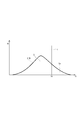
- FIG. 4 is a view showing a particle size distribution curve of the powder for powder magnetic cores of the first embodiment
- FIG. 5 is a diagram showing the iron loss of the powder for powder magnetic cores of the first embodiment
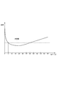
- FIG. 6 is a relationship diagram showing the reciprocal of the crystal grain diameter of the powder for powder magnetic cores of the first embodiment and the hysteresis loss
- FIG. 7 is a diagram showing the relationship between the second maximum value and the core loss of the powder for powder magnetic cores of the first embodiment
- FIG. 8 is a relationship diagram showing the median diameter and the eddy current loss of the powder for powder magnetic cores of the first embodiment
- FIG. 9 is a flowchart for explaining measurement of the crystal grain size of the powder for powder magnetic cores of the second embodiment
- FIG. 10 is a relationship diagram showing the reciprocal of the crystal grain diameter of the powder for powder magnetic cores of the second embodiment and the hysteresis loss
- FIG. 11 is a relationship diagram showing the reciprocal of the crystal grain diameter of the powder for powder magnetic cores of the second embodiment and the hysteresis loss
- FIG. 12 is a view showing a number distribution curve of powder for dust core of the third embodiment
- FIG. 13 is a relationship diagram showing the reciprocal of the crystal grain size and the hysteresis loss of the powder for powder magnetic cores of the third embodiment
- FIG. 14 is a relationship diagram showing crystal grains and iron loss of the powder for powder magnetic cores of the third embodiment.
- the powder for powder magnetic cores of the present embodiment is used for manufacturing a powder magnetic core.
- This dust core is used for a core such as a motor rotor or a stator, a reactor or an ignition coil.
- the powder for dust core 1 is a ferromagnetic or soft magnetic metal powder, is provided with a plurality of crystal grains 2, and is an aggregate of crystal grains 2.
- the powder 1 for powder magnetic cores is, for example, pure iron particles, iron-based alloy particles, amorphous particles or the like.
- the iron-based alloy particles are, for example, an Fe-Al alloy, an Fe-Si alloy, Sendust or Permalloy.
- the grain size of the crystal grain 2 is taken as the grain size D [ ⁇ m].
- the ratio of the number of crystal grains 2 in each crystal grain size D to the number of crystal grains 2 whose grain size is measured is taken as the number ratio Rv [%].
- the crystal grain 2 has a first particle 21 and a second particle 22.
- the first particles 21 and the second particles 22 are prepared by an atomizing method, a mechanical crushing method, a reduction method or the like.
- the atomizing method is, for example, a water atomizing method, a gas atomizing method, or a gas water atomizing method.
- the first particles 21 and the second particles 22 are powders whose particle sizes are adjusted using a sieve.
- the first particles 21 can pass through a sieve having an aperture of 90 ⁇ m or more and 180 ⁇ m or less.
- an opening is one of the references
- the second particles 22 can pass through a sieve having an opening of 212 ⁇ m or more and 250 ⁇ m or less.
- the ratio of the weight of the second particles 22 to the total weight of the powder 1 for dust cores is taken as the second particle weight ratio W2.
- the first particles 21 and the second particles 22 are mixed so that the second particle weight ratio W2 is 20% or more and 50% or less, and the powder magnetic core powder 1 is adjusted.
- the prepared powder 1 for powder magnetic cores is filled in a mold.
- the powder for powder magnetic core 1 filled in is press-formed so that the density becomes a predetermined value.
- the predetermined value is set arbitrarily, and is set so that iron loss, hysteresis loss and eddy current loss can be easily measured.
- the press-formed powder for powder magnetic core 1 is annealed in vacuum at a predetermined temperature and for a predetermined time to remove strain.
- the crystal grain diameter D of the annealed powder for powder magnetic core 1 is measured by a metallurgical microscope. After measurement of the crystal grain size D, iron loss, hysteresis loss and eddy current loss of the powder 1 for powder magnetic cores are measured.
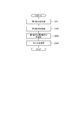
- step 101 the first particles 21 are produced using a sieve having an opening of not less than 90 ⁇ m and not more than 180 ⁇ m.
- step 102 second particles 22 are produced using a sieve having an opening of 212 ⁇ m or more and 250 ⁇ m or less.
- step 103 the first particles 21 and the second particles 22 are mixed so that the second particle weight ratio W2 is 20% or more and 50% or less, and the powder 1 for powder magnetic cores is adjusted.
- step 104 the adjusted powder magnetic core powder 1 is filled in a mold and pressed.
- step 105 the press-formed powder 1 for powder magnetic cores is annealed.
- step 106 the powder magnetic core powder 1 is embedded in a resin.
- step 107 the resin in which the powder 1 for powder magnetic cores is embedded is cut so that the cross section of the powder 1 for powder magnetic cores is exposed.
- step 108 the cross section of the exposed powder magnetic core powder 1 is mirror-polished.
- step 109 the mirror-polished cross section is etched.
- the etched cross section is observed at a magnification of 100-400 using an optical microscope.
- a plurality of locations of the etched cross section are photographed. In the first embodiment, five to ten locations are photographed.
- 100 or more of crystal grains 2 of powder 1 for powder magnetic cores embedded in resin are observed.
- step 111 the crystal grain 2 to be a subject is image-analyzed from the photographed picture. In image analysis, an image processing program is used.
- a plurality of parallel lines P are drawn at a predetermined interval for one image.
- the crystal grain 2 is exaggerated and described.
- five parallel lines P are drawn so as to extend in the left-right direction of the paper surface.
- the distance between the parallel line P and the grain boundary 3 which is the interface or end face between the crystal grains 2 is defined as inter-intersection distance Li.
- the inter-intersection distance Li is measured in accordance with the number of intersections of the grain boundaries 3 of one crystal grain 2 with the parallel lines P.
- the average value of the measured inter-intersection distances Li is taken as the crystal grain diameter D.
- the crystal grain diameter D of the crystal grain 2 is excluded from measurement.
- the points of intersection are indicated by black circles.
- the number ratio Rv is calculated from the measured crystal grain diameter D.
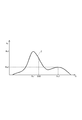
- Each grain size D and number ratio Rv are plotted, and a grain size distribution curve C is drawn, which is a curve connecting the plotted points.
- the powder 1 for dust cores has at least two maximum values in the particle size distribution curve C.
- an axis extending in the left-right direction with respect to the drawing is the axis of the crystal grain diameter D
- an axis extending in the vertical direction with respect to the drawing is the number ratio Rv.
- the maximum value is a point at which the slope of the tangent becomes zero in the grain size distribution curve C, and is a turning point where the sign of the slope of the tangent changes from positive to negative with the increase of the crystal grain size D.
- “zero” includes a common sense error range.
- One maximum value is taken as a first maximum value Rv1 [%].
- the other maximum value is taken as a second maximum value Rv2 [%].
- the crystal grain size D corresponding to the first maximum value Rv1 is taken as a first grain size Dv1 [ ⁇ m].
- the crystal grain size D corresponding to the second maximum value is taken as a second grain size Dv2 [ ⁇ m].
- the second particle diameter Dv2 is larger than the first particle diameter Dv1.
- the powder 1 for dust cores is adjusted so that the second particle diameter Dv2 is 50 ⁇ m or more and the second maximum value Rv2 is 5-35%.
- the powder 1 for powder magnetic cores is adjusted such that the median diameter D50 [ ⁇ m] is 30 ⁇ m or less.
- the median diameter D50 is the crystal grain diameter D when the number ratio Rv is 50%.
- a powder magnetic core was formed using powder 1 for powder magnetic cores, and loss measurement of a motor using the powder magnetic core was measured based on JIS_C_4034-2-1. Hysteresis loss is proportional to frequency, and eddy current loss is proportional to the square of frequency. Therefore, the iron loss can be separated into the hysteresis loss and the eddy current from the relation between the iron loss of each frequency and the frequency.
- a powder magnetic core using a powder for powder magnetic cores having a crystal grain size of 70% or more as described in Patent Document 1 as 50 ⁇ m or more is taken as a comparative example. The iron loss of the powder magnetic core using the powder 1 for powder magnetic cores of this embodiment and the iron loss of the comparative example were compared.
- the larger the crystal grain size of the powder for powder magnetic cores the larger the grain boundary interface.
- the domain wall which is the boundary between the magnetic domain and the magnetic domain representing a region in which the spins are oriented in the same direction, is easily moved, and the hysteresis loss is reduced.
- the larger the grain size of the powder for powder magnetic core the larger the area in the grain, and the larger the eddy current in the grain. Therefore, the eddy current loss increases.
- the eddy current loss increases.
- the powder 1 for powder magnetic cores of the present embodiment achieves both a reduction in hysteresis loss and a reduction in eddy current loss to reduce iron loss.
- the core loss of the powder magnetic core powder 1 is reduced by about 48% in core loss as compared with the comparative example. Among them, the hysteresis loss is reduced by about 43%, and the eddy current loss is reduced by 5%.
- the powder 1 for powder magnetic cores has at least two maximum values in the particle size distribution curve C.
- the second particle diameter Dv2 and the second maximum value Rv2 By adjusting the second particle diameter Dv2 and the second maximum value Rv2, the number ratio Rv of the relatively large crystal particle diameter D can be increased. Thereby, the interface of the grain boundary 3 becomes large, and the domain wall can be easily moved. Thus, hysteresis loss is reduced.
- the median diameter D50 can be reduced by adjusting the first particle diameter Dv1 and the first maximum value Rv1. Thereby, the eddy current loss is reduced. Therefore, both the hysteresis loss and the eddy current loss can be reduced to achieve low core loss.
- the hysteresis loss decreases.
- the reciprocal of second particle diameter Dv2 is 0.02 or less, that is, second particle diameter Dv2 is 50 ⁇ m or more
- the hysteresis loss is It becomes less than the allowable value.
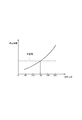
- the second maximum value Rv2 increases, that is, as the number ratio Rv of the relatively large crystal grain diameter D increases, the hysteresis loss decreases. Thus, iron loss is reduced. The iron loss is minimized when the second maximum value Rv2 is 20%. Furthermore, when the second maximum value Rv2 is increased, the median diameter D50 is increased, and the eddy current loss is increased. As a result, iron loss increases. When the second maximum value Rv2 is 5-35%, the iron loss is equal to or less than the allowable value, when examined based on the characteristics of the powder 1 for powder magnetic cores used in the present embodiment.
- the eddy current loss decreases as the median diameter D50 of the powder 1 for dust core is reduced. If it investigates based on the characteristic regarding the powder 1 for powder magnetic cores used for this embodiment, when the median diameter D50 of the powder 1 for powder magnetic cores is 30 micrometers or less, an eddy current loss will become below an allowance.
- the first particles 21 and the second particles 22 are mixed so that the second particle weight ratio W2 is 20% or more and 50% or less. This makes it easy to adjust the second particle diameter Dv2 and the second maximum value Rv2 in the particle diameter distribution curve C of the powder 1 for powder magnetic cores.
- the second embodiment is the same as the first embodiment except that the measurement of the crystal grain size is different.
- the particle size measurement may vary depending on the measuring method.
- the powder 1 is measured using a light.
- Each crystal grain diameter D of the powder 1 for powder magnetic cores is measured based on JIS_Z_8825.
- step 204 the crystal grain diameter D of the crystal grain 2 in the powder 1 for dust core is measured by a diffraction method using light such as a laser. When light passes through the crystal grain 2, the light is scattered. The larger the angle of scattered light, the smaller the crystal grain size D.
- the crystal grain size D is measured by measuring and analyzing the angle of the scattered light.
- the grain size distribution curve C is drawn using the crystal grain size D measured by light. Also in the second embodiment, the same effects as in [1] of the first embodiment can be obtained.
- the hysteresis loss decreases.
- the reciprocal of the second particle diameter Dv2 is 0.0047 or less, that is, the second particle diameter Dv2 is 212 ⁇ m or more
- the hysteresis loss is It becomes less than the allowable value.
- the second maximum value Rv2 is 5-35%
- the iron loss becomes equal to or less than the allowable value.
- the eddy current loss is reduced as the median diameter D50 of the powder 1 for powder magnetic cores is reduced. If examined based on the characteristic regarding the powder 1 for powder magnetic cores used for this embodiment, when the median diameter D50 of the powder 1 for powder magnetic cores is 180 micrometers or less, an eddy current loss will become below an allowance.
- the third embodiment is the same as the first embodiment except that the particle diameter distribution curve of the powder for powder magnetic cores is different.
- the powder magnetic core powder 1 of the third embodiment has the number of crystal grains 2 having a crystal grain size D of 50 ⁇ m or more with respect to the number of crystal grains 2 whose grain sizes are measured. The proportion has been adjusted to 5-35%.
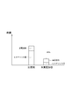
- a number distribution curve C_N is described in which an axis extending in the lateral direction with respect to the drawing is the axis of the grain size D and an axis extending in the vertical direction with respect to the drawing is the number N of crystal grains 2.
- the total area S which is the area divided by the axis of the crystal grain diameter D and the number distribution curve C_N corresponds to the total number of crystal grains 2.
- a straight line parallel to the axis of the number N and intersecting with the axis of the crystal grain diameter D and the number distribution curve C_N is defined as a dividing line L.
- the value of the intersection of the dividing line L and the axis of the crystal grain diameter D is taken as an intersection value Di [ ⁇ m].
- the area divided by the dividing line L, the axis of the crystal grain diameter D, and the number distribution curve C_N is taken as a partial area Sp.
- the partial area Sp corresponds to the number of crystal grains 2 whose crystal grain size D is equal to or greater than the intersection value Di.
- the powder magnetic core powder 1 of the third embodiment is adjusted such that the intersection value Di is 50 ⁇ m or more and the ratio Sp / S [%] of the partial area Sp to the total area S is 5-35%. Also in the third embodiment, the same effects as in [1] of the first embodiment can be obtained.
- the partial area Sp is made constant, the intersection value Di is changed, and the hysteresis loss of the powder magnetic core using the powder 1 for powder magnetic cores of the third embodiment is measured.
- the reciprocal of the intersection value Di and the hysteresis loss are plotted.
- the ratio Sp / S increases, the number ratio Rv of relatively large crystal grain sizes D increases. This reduces the hysteresis loss. Thus, iron loss is reduced. Furthermore, as the ratio Sp / S increases, the median diameter D50 increases and the eddy current loss increases. As a result, iron loss increases. When the ratio Sp / S is 5-35% when examined based on the characteristics of the powder 1 for powder magnetic cores used in the present embodiment, the iron loss becomes less than the allowable value.
- the grain size D may be measured by image analysis as follows. In image analysis, the center of gravity of the cross section of the crystal grain is determined. A straight line is drawn on the cross section of the crystal grain 2 so as to pass through the center of gravity. Inter-point distance Li between this straight line and the outer edge of the cross section of crystal grain 2 is measured. This is measured at 180 points in steps of 2 degrees, and the average of the measurement results is taken as the crystal grain size D.
- the number of crystal grains 2 for measuring the crystal grain size D is at least 50.
- the number of crystal grains 2 for measuring the crystal grain size D should be as large as possible.
- the number of crystal grains 2 for measuring the crystal grain size D may be 60 or more, or 70 or more.
- the crystal grain 2 is selected so that the variation does not occur extremely when the particle size distribution of the powder 1 for powder magnetic cores is taken into consideration.
- the method of measuring the crystal grain size D of the powder for dust core may be a centrifugal sedimentation method or an electrical detection method.
- a film having insulating properties may be formed on the powder for powder magnetic cores by using ferrite or the like. By forming the insulating film on the powder for powder magnetic core, the eddy current loss can be further reduced.
- the number of maximum values is not limited to two, and may be two or more. The greater the number of maxima, the easier it is to reduce the hysteresis loss and the eddy current loss.
Landscapes
- Engineering & Computer Science (AREA)
- Power Engineering (AREA)
- Chemical & Material Sciences (AREA)
- Dispersion Chemistry (AREA)
- Manufacturing & Machinery (AREA)
- Powder Metallurgy (AREA)
- Soft Magnetic Materials (AREA)
Priority Applications (2)
| Application Number | Priority Date | Filing Date | Title |
|---|---|---|---|
| DE112018003960.9T DE112018003960T5 (de) | 2017-08-02 | 2018-07-18 | Pulver für eisenkern und eisenkern |
| US16/774,865 US11532414B2 (en) | 2017-08-02 | 2020-01-28 | Powder for dust core and dust core |
Applications Claiming Priority (2)
| Application Number | Priority Date | Filing Date | Title |
|---|---|---|---|
| JP2017-149937 | 2017-08-02 | ||
| JP2017149937A JP6777041B2 (ja) | 2017-08-02 | 2017-08-02 | 圧粉磁心用粉末および圧粉磁心 |
Related Child Applications (1)
| Application Number | Title | Priority Date | Filing Date |
|---|---|---|---|
| US16/774,865 Continuation US11532414B2 (en) | 2017-08-02 | 2020-01-28 | Powder for dust core and dust core |
Publications (1)
| Publication Number | Publication Date |
|---|---|
| WO2019026612A1 true WO2019026612A1 (ja) | 2019-02-07 |
Family
ID=65232682
Family Applications (1)
| Application Number | Title | Priority Date | Filing Date |
|---|---|---|---|
| PCT/JP2018/026806 Ceased WO2019026612A1 (ja) | 2017-08-02 | 2018-07-18 | 圧粉磁心用粉末および圧粉磁心 |
Country Status (4)
| Country | Link |
|---|---|
| US (1) | US11532414B2 (enExample) |
| JP (1) | JP6777041B2 (enExample) |
| DE (1) | DE112018003960T5 (enExample) |
| WO (1) | WO2019026612A1 (enExample) |
Families Citing this family (1)
| Publication number | Priority date | Publication date | Assignee | Title |
|---|---|---|---|---|
| DE102020207625A1 (de) | 2020-06-05 | 2021-12-09 | Siemens Aktiengesellschaft | Elektrischer Motor |
Citations (5)
| Publication number | Priority date | Publication date | Assignee | Title |
|---|---|---|---|---|
| JP2003517195A (ja) * | 1999-12-14 | 2003-05-20 | ローベルト ボツシユ ゲゼルシヤフト ミツト ベシユレンクテル ハフツング | 焼結した軟磁性複合材料及びその製造方法 |
| JP2004296606A (ja) * | 2003-03-26 | 2004-10-21 | Jfe Steel Kk | 保磁力の低い磁心とその製造方法およびその磁心用鉄粉 |
| JP2007012745A (ja) * | 2005-06-29 | 2007-01-18 | Sumitomo Electric Ind Ltd | 圧粉磁心およびその製造方法 |
| JP2012212855A (ja) * | 2011-03-24 | 2012-11-01 | Sumitomo Electric Ind Ltd | 複合材料、リアクトル用コア、及びリアクトル |
| WO2016043025A1 (ja) * | 2014-09-17 | 2016-03-24 | 株式会社オートネットワーク技術研究所 | 複合材料、磁気部品、及びリアクトル |
Family Cites Families (2)
| Publication number | Priority date | Publication date | Assignee | Title |
|---|---|---|---|---|
| JP4630251B2 (ja) | 2006-09-11 | 2011-02-09 | 株式会社神戸製鋼所 | 圧粉磁心および圧粉磁心用の鉄基粉末 |
| JP6977229B2 (ja) | 2016-02-24 | 2021-12-08 | クラレプラスチックス株式会社 | 熱可塑性樹脂組成物およびそれを用いた布積層成形体 |
-
2017
- 2017-08-02 JP JP2017149937A patent/JP6777041B2/ja active Active
-
2018
- 2018-07-18 DE DE112018003960.9T patent/DE112018003960T5/de active Pending
- 2018-07-18 WO PCT/JP2018/026806 patent/WO2019026612A1/ja not_active Ceased
-
2020
- 2020-01-28 US US16/774,865 patent/US11532414B2/en active Active
Patent Citations (5)
| Publication number | Priority date | Publication date | Assignee | Title |
|---|---|---|---|---|
| JP2003517195A (ja) * | 1999-12-14 | 2003-05-20 | ローベルト ボツシユ ゲゼルシヤフト ミツト ベシユレンクテル ハフツング | 焼結した軟磁性複合材料及びその製造方法 |
| JP2004296606A (ja) * | 2003-03-26 | 2004-10-21 | Jfe Steel Kk | 保磁力の低い磁心とその製造方法およびその磁心用鉄粉 |
| JP2007012745A (ja) * | 2005-06-29 | 2007-01-18 | Sumitomo Electric Ind Ltd | 圧粉磁心およびその製造方法 |
| JP2012212855A (ja) * | 2011-03-24 | 2012-11-01 | Sumitomo Electric Ind Ltd | 複合材料、リアクトル用コア、及びリアクトル |
| WO2016043025A1 (ja) * | 2014-09-17 | 2016-03-24 | 株式会社オートネットワーク技術研究所 | 複合材料、磁気部品、及びリアクトル |
Also Published As
| Publication number | Publication date |
|---|---|
| DE112018003960T5 (de) | 2020-05-07 |
| US20200168377A1 (en) | 2020-05-28 |
| JP6777041B2 (ja) | 2020-10-28 |
| US11532414B2 (en) | 2022-12-20 |
| JP2019026912A (ja) | 2019-02-21 |
Similar Documents
| Publication | Publication Date | Title |
|---|---|---|
| Kohashi et al. | Magnetism in grain-boundary phase of a NdFeB sintered magnet studied by spin-polarized scanning electron microscopy | |
| US9067833B2 (en) | Iron oxide and silica magnetic core | |
| Yamamoto et al. | Dipolar ferromagnetic phase transition in Fe3O4 nanoparticle arrays observed by Lorentz microscopy and electron holography | |
| JP2016162764A (ja) | 磁性粉末混合樹脂材料 | |
| JP4909312B2 (ja) | 圧粉磁心用軟磁性材および圧粉磁心 | |
| WO2019026612A1 (ja) | 圧粉磁心用粉末および圧粉磁心 | |
| Qu et al. | The effect of powder shape on the magnetic anisotropy in NdFeB bonded magnets | |
| Olekšáková et al. | Energy loss separation in NiFeMo compacts with smoothed powders according to Landgraf’s and Bertotti’s theories | |
| JP6493428B2 (ja) | 高透磁率磁性シート | |
| JPH07509353A (ja) | 医療用高磁界磁石 | |
| Fang et al. | Influence of alloy composition on the overall performance of gas-atomized Fe–Si powder cores | |
| JP3115466B2 (ja) | 六方晶フェライト粒子の製造方法 | |
| Lu et al. | Core loss analysis of amorphous motor considering the effect of cutting damage | |
| Luo et al. | The influence of fine powder content on the properties of FeNi50 soft magnetic composites | |
| JPH05222493A (ja) | Fe系高透磁率非晶質合金 | |
| WO2011046125A1 (ja) | 高周波用磁性材料及び高周波デバイス | |
| Aytekin et al. | Investigation of the structural and magnetic properties of rapidly solidified Nd–Fe–B–Ce alloys | |
| JP2022122349A (ja) | 軟磁性扁平粉末 | |
| D’Aloia et al. | A Novel Computational Method to Identify/Analyze Hysteresis Loops of Hard Magnetic Materials. Magnetochemistry 2021, 7, 10 | |
| CN119678229A (zh) | 各向同性颗粒薄膜 | |
| WO2019124224A1 (ja) | 非晶質合金粒子、及び、非晶質合金粒子の製造方法 | |
| Duong et al. | Processing-Driven Microstructure Control in Additively Manufactured Alnico Permanent Magnets | |
| Feliciano | Development and characterisation of soft magnetic iron-silicon alloys for laser beam powder bed fusion additive manufacturing | |
| Saito et al. | Production of anisotropic SmFe3 magnets by hot deformation | |
| KR102620616B1 (ko) | 자성부재용 난연성분말 및 폴리머 조성물 |
Legal Events
| Date | Code | Title | Description |
|---|---|---|---|
| 121 | Ep: the epo has been informed by wipo that ep was designated in this application |
Ref document number: 18841297 Country of ref document: EP Kind code of ref document: A1 |
|
| 122 | Ep: pct application non-entry in european phase |
Ref document number: 18841297 Country of ref document: EP Kind code of ref document: A1 |