WO2019026532A1 - 冷凍サイクル装置 - Google Patents
冷凍サイクル装置 Download PDFInfo
- Publication number
- WO2019026532A1 WO2019026532A1 PCT/JP2018/025545 JP2018025545W WO2019026532A1 WO 2019026532 A1 WO2019026532 A1 WO 2019026532A1 JP 2018025545 W JP2018025545 W JP 2018025545W WO 2019026532 A1 WO2019026532 A1 WO 2019026532A1
- Authority
- WO
- WIPO (PCT)
- Prior art keywords
- heat
- temperature side
- heating
- refrigerant
- air
- Prior art date
- Legal status (The legal status is an assumption and is not a legal conclusion. Google has not performed a legal analysis and makes no representation as to the accuracy of the status listed.)
- Ceased
Links
Images

Classifications
-
- B—PERFORMING OPERATIONS; TRANSPORTING
- B60—VEHICLES IN GENERAL
- B60H—ARRANGEMENTS OF HEATING, COOLING, VENTILATING OR OTHER AIR-TREATING DEVICES SPECIALLY ADAPTED FOR PASSENGER OR GOODS SPACES OF VEHICLES
- B60H1/00—Heating, cooling or ventilating devices
- B60H1/22—Heating, cooling or ventilating devices the heat source being other than the propulsion plant
-
- F—MECHANICAL ENGINEERING; LIGHTING; HEATING; WEAPONS; BLASTING
- F24—HEATING; RANGES; VENTILATING
- F24D—DOMESTIC- OR SPACE-HEATING SYSTEMS, e.g. CENTRAL HEATING SYSTEMS; DOMESTIC HOT-WATER SUPPLY SYSTEMS; ELEMENTS OR COMPONENTS THEREFOR
- F24D17/00—Domestic hot-water supply systems
- F24D17/0005—Domestic hot-water supply systems using recuperation of waste heat
-
- B—PERFORMING OPERATIONS; TRANSPORTING
- B60—VEHICLES IN GENERAL
- B60H—ARRANGEMENTS OF HEATING, COOLING, VENTILATING OR OTHER AIR-TREATING DEVICES SPECIALLY ADAPTED FOR PASSENGER OR GOODS SPACES OF VEHICLES
- B60H1/00—Heating, cooling or ventilating devices
- B60H1/00642—Control systems or circuits; Control members or indication devices for heating, cooling or ventilating devices
- B60H1/00814—Control systems or circuits characterised by their output, for controlling particular components of the heating, cooling or ventilating installation
- B60H1/00878—Control systems or circuits characterised by their output, for controlling particular components of the heating, cooling or ventilating installation the components being temperature regulating devices
- B60H1/00899—Controlling the flow of liquid in a heat pump system
- B60H1/00921—Controlling the flow of liquid in a heat pump system where the flow direction of the refrigerant does not change and there is an extra subcondenser, e.g. in an air duct
-
- B—PERFORMING OPERATIONS; TRANSPORTING
- B60—VEHICLES IN GENERAL
- B60H—ARRANGEMENTS OF HEATING, COOLING, VENTILATING OR OTHER AIR-TREATING DEVICES SPECIALLY ADAPTED FOR PASSENGER OR GOODS SPACES OF VEHICLES
- B60H1/00—Heating, cooling or ventilating devices
- B60H1/32—Cooling devices
-
- B—PERFORMING OPERATIONS; TRANSPORTING
- B60—VEHICLES IN GENERAL
- B60H—ARRANGEMENTS OF HEATING, COOLING, VENTILATING OR OTHER AIR-TREATING DEVICES SPECIALLY ADAPTED FOR PASSENGER OR GOODS SPACES OF VEHICLES
- B60H1/00—Heating, cooling or ventilating devices
- B60H1/32—Cooling devices
- B60H1/3204—Cooling devices using compression
- B60H1/3228—Cooling devices using compression characterised by refrigerant circuit configurations
- B60H1/32284—Cooling devices using compression characterised by refrigerant circuit configurations comprising two or more secondary circuits, e.g. at evaporator and condenser side
-
- F—MECHANICAL ENGINEERING; LIGHTING; HEATING; WEAPONS; BLASTING
- F25—REFRIGERATION OR COOLING; COMBINED HEATING AND REFRIGERATION SYSTEMS; HEAT PUMP SYSTEMS; MANUFACTURE OR STORAGE OF ICE; LIQUEFACTION SOLIDIFICATION OF GASES
- F25B—REFRIGERATION MACHINES, PLANTS OR SYSTEMS; COMBINED HEATING AND REFRIGERATION SYSTEMS; HEAT PUMP SYSTEMS
- F25B25/00—Machines, plants or systems, using a combination of modes of operation covered by two or more of the groups F25B1/00 - F25B23/00
- F25B25/005—Machines, plants or systems, using a combination of modes of operation covered by two or more of the groups F25B1/00 - F25B23/00 using primary and secondary systems
-
- F—MECHANICAL ENGINEERING; LIGHTING; HEATING; WEAPONS; BLASTING
- F25—REFRIGERATION OR COOLING; COMBINED HEATING AND REFRIGERATION SYSTEMS; HEAT PUMP SYSTEMS; MANUFACTURE OR STORAGE OF ICE; LIQUEFACTION SOLIDIFICATION OF GASES
- F25B—REFRIGERATION MACHINES, PLANTS OR SYSTEMS; COMBINED HEATING AND REFRIGERATION SYSTEMS; HEAT PUMP SYSTEMS
- F25B27/00—Machines, plants or systems, using particular sources of energy
- F25B27/02—Machines, plants or systems, using particular sources of energy using waste heat, e.g. from internal-combustion engines
-
- F—MECHANICAL ENGINEERING; LIGHTING; HEATING; WEAPONS; BLASTING
- F25—REFRIGERATION OR COOLING; COMBINED HEATING AND REFRIGERATION SYSTEMS; HEAT PUMP SYSTEMS; MANUFACTURE OR STORAGE OF ICE; LIQUEFACTION SOLIDIFICATION OF GASES
- F25B—REFRIGERATION MACHINES, PLANTS OR SYSTEMS; COMBINED HEATING AND REFRIGERATION SYSTEMS; HEAT PUMP SYSTEMS
- F25B29/00—Combined heating and refrigeration systems, e.g. operating alternately or simultaneously
- F25B29/003—Combined heating and refrigeration systems, e.g. operating alternately or simultaneously of the compression type system
-
- F—MECHANICAL ENGINEERING; LIGHTING; HEATING; WEAPONS; BLASTING
- F25—REFRIGERATION OR COOLING; COMBINED HEATING AND REFRIGERATION SYSTEMS; HEAT PUMP SYSTEMS; MANUFACTURE OR STORAGE OF ICE; LIQUEFACTION SOLIDIFICATION OF GASES
- F25B—REFRIGERATION MACHINES, PLANTS OR SYSTEMS; COMBINED HEATING AND REFRIGERATION SYSTEMS; HEAT PUMP SYSTEMS
- F25B41/00—Fluid-circulation arrangements
- F25B41/20—Disposition of valves, e.g. of on-off valves or flow control valves
-
- F—MECHANICAL ENGINEERING; LIGHTING; HEATING; WEAPONS; BLASTING
- F25—REFRIGERATION OR COOLING; COMBINED HEATING AND REFRIGERATION SYSTEMS; HEAT PUMP SYSTEMS; MANUFACTURE OR STORAGE OF ICE; LIQUEFACTION SOLIDIFICATION OF GASES
- F25B—REFRIGERATION MACHINES, PLANTS OR SYSTEMS; COMBINED HEATING AND REFRIGERATION SYSTEMS; HEAT PUMP SYSTEMS
- F25B41/00—Fluid-circulation arrangements
- F25B41/20—Disposition of valves, e.g. of on-off valves or flow control valves
- F25B41/24—Arrangement of shut-off valves for disconnecting a part of the refrigerant cycle, e.g. an outdoor part
-
- F—MECHANICAL ENGINEERING; LIGHTING; HEATING; WEAPONS; BLASTING
- F25—REFRIGERATION OR COOLING; COMBINED HEATING AND REFRIGERATION SYSTEMS; HEAT PUMP SYSTEMS; MANUFACTURE OR STORAGE OF ICE; LIQUEFACTION SOLIDIFICATION OF GASES
- F25B—REFRIGERATION MACHINES, PLANTS OR SYSTEMS; COMBINED HEATING AND REFRIGERATION SYSTEMS; HEAT PUMP SYSTEMS
- F25B49/00—Arrangement or mounting of control or safety devices
- F25B49/02—Arrangement or mounting of control or safety devices for compression type machines, plants or systems
-
- F—MECHANICAL ENGINEERING; LIGHTING; HEATING; WEAPONS; BLASTING
- F25—REFRIGERATION OR COOLING; COMBINED HEATING AND REFRIGERATION SYSTEMS; HEAT PUMP SYSTEMS; MANUFACTURE OR STORAGE OF ICE; LIQUEFACTION SOLIDIFICATION OF GASES
- F25B—REFRIGERATION MACHINES, PLANTS OR SYSTEMS; COMBINED HEATING AND REFRIGERATION SYSTEMS; HEAT PUMP SYSTEMS
- F25B5/00—Compression machines, plants or systems, with several evaporator circuits, e.g. for varying refrigerating capacity
- F25B5/02—Compression machines, plants or systems, with several evaporator circuits, e.g. for varying refrigerating capacity arranged in parallel
-
- B—PERFORMING OPERATIONS; TRANSPORTING
- B60—VEHICLES IN GENERAL
- B60H—ARRANGEMENTS OF HEATING, COOLING, VENTILATING OR OTHER AIR-TREATING DEVICES SPECIALLY ADAPTED FOR PASSENGER OR GOODS SPACES OF VEHICLES
- B60H1/00—Heating, cooling or ventilating devices
- B60H1/00642—Control systems or circuits; Control members or indication devices for heating, cooling or ventilating devices
- B60H1/00814—Control systems or circuits characterised by their output, for controlling particular components of the heating, cooling or ventilating installation
- B60H1/00878—Control systems or circuits characterised by their output, for controlling particular components of the heating, cooling or ventilating installation the components being temperature regulating devices
- B60H2001/00928—Control systems or circuits characterised by their output, for controlling particular components of the heating, cooling or ventilating installation the components being temperature regulating devices comprising a secondary circuit
-
- B—PERFORMING OPERATIONS; TRANSPORTING
- B60—VEHICLES IN GENERAL
- B60H—ARRANGEMENTS OF HEATING, COOLING, VENTILATING OR OTHER AIR-TREATING DEVICES SPECIALLY ADAPTED FOR PASSENGER OR GOODS SPACES OF VEHICLES
- B60H1/00—Heating, cooling or ventilating devices
- B60H1/00642—Control systems or circuits; Control members or indication devices for heating, cooling or ventilating devices
- B60H1/00814—Control systems or circuits characterised by their output, for controlling particular components of the heating, cooling or ventilating installation
- B60H1/00878—Control systems or circuits characterised by their output, for controlling particular components of the heating, cooling or ventilating installation the components being temperature regulating devices
- B60H2001/00949—Control systems or circuits characterised by their output, for controlling particular components of the heating, cooling or ventilating installation the components being temperature regulating devices comprising additional heating/cooling sources, e.g. second evaporator
-
- F—MECHANICAL ENGINEERING; LIGHTING; HEATING; WEAPONS; BLASTING
- F25—REFRIGERATION OR COOLING; COMBINED HEATING AND REFRIGERATION SYSTEMS; HEAT PUMP SYSTEMS; MANUFACTURE OR STORAGE OF ICE; LIQUEFACTION SOLIDIFICATION OF GASES
- F25B—REFRIGERATION MACHINES, PLANTS OR SYSTEMS; COMBINED HEATING AND REFRIGERATION SYSTEMS; HEAT PUMP SYSTEMS
- F25B2339/00—Details of evaporators; Details of condensers
- F25B2339/04—Details of condensers
- F25B2339/047—Water-cooled condensers
-
- F—MECHANICAL ENGINEERING; LIGHTING; HEATING; WEAPONS; BLASTING
- F25—REFRIGERATION OR COOLING; COMBINED HEATING AND REFRIGERATION SYSTEMS; HEAT PUMP SYSTEMS; MANUFACTURE OR STORAGE OF ICE; LIQUEFACTION SOLIDIFICATION OF GASES
- F25B—REFRIGERATION MACHINES, PLANTS OR SYSTEMS; COMBINED HEATING AND REFRIGERATION SYSTEMS; HEAT PUMP SYSTEMS
- F25B2400/00—Component parts or details not otherwise provided for in this subclass
- F25B2400/04—Refrigeration circuit bypassing means
- F25B2400/0403—Refrigeration circuit bypassing means for condensers
-
- F—MECHANICAL ENGINEERING; LIGHTING; HEATING; WEAPONS; BLASTING
- F25—REFRIGERATION OR COOLING; COMBINED HEATING AND REFRIGERATION SYSTEMS; HEAT PUMP SYSTEMS; MANUFACTURE OR STORAGE OF ICE; LIQUEFACTION SOLIDIFICATION OF GASES
- F25B—REFRIGERATION MACHINES, PLANTS OR SYSTEMS; COMBINED HEATING AND REFRIGERATION SYSTEMS; HEAT PUMP SYSTEMS
- F25B2600/00—Control issues
- F25B2600/02—Compressor control
- F25B2600/026—Compressor control by controlling unloaders
- F25B2600/0261—Compressor control by controlling unloaders external to the compressor
-
- F—MECHANICAL ENGINEERING; LIGHTING; HEATING; WEAPONS; BLASTING
- F25—REFRIGERATION OR COOLING; COMBINED HEATING AND REFRIGERATION SYSTEMS; HEAT PUMP SYSTEMS; MANUFACTURE OR STORAGE OF ICE; LIQUEFACTION SOLIDIFICATION OF GASES
- F25B—REFRIGERATION MACHINES, PLANTS OR SYSTEMS; COMBINED HEATING AND REFRIGERATION SYSTEMS; HEAT PUMP SYSTEMS
- F25B2600/00—Control issues
- F25B2600/25—Control of valves
- F25B2600/2501—Bypass valves
-
- F—MECHANICAL ENGINEERING; LIGHTING; HEATING; WEAPONS; BLASTING
- F25—REFRIGERATION OR COOLING; COMBINED HEATING AND REFRIGERATION SYSTEMS; HEAT PUMP SYSTEMS; MANUFACTURE OR STORAGE OF ICE; LIQUEFACTION SOLIDIFICATION OF GASES
- F25B—REFRIGERATION MACHINES, PLANTS OR SYSTEMS; COMBINED HEATING AND REFRIGERATION SYSTEMS; HEAT PUMP SYSTEMS
- F25B2700/00—Sensing or detecting of parameters; Sensors therefor
- F25B2700/21—Temperatures
- F25B2700/2117—Temperatures of an evaporator
-
- F—MECHANICAL ENGINEERING; LIGHTING; HEATING; WEAPONS; BLASTING
- F25—REFRIGERATION OR COOLING; COMBINED HEATING AND REFRIGERATION SYSTEMS; HEAT PUMP SYSTEMS; MANUFACTURE OR STORAGE OF ICE; LIQUEFACTION SOLIDIFICATION OF GASES
- F25B—REFRIGERATION MACHINES, PLANTS OR SYSTEMS; COMBINED HEATING AND REFRIGERATION SYSTEMS; HEAT PUMP SYSTEMS
- F25B6/00—Compression machines, plants or systems, with several condenser circuits
- F25B6/04—Compression machines, plants or systems, with several condenser circuits arranged in series
-
- Y—GENERAL TAGGING OF NEW TECHNOLOGICAL DEVELOPMENTS; GENERAL TAGGING OF CROSS-SECTIONAL TECHNOLOGIES SPANNING OVER SEVERAL SECTIONS OF THE IPC; TECHNICAL SUBJECTS COVERED BY FORMER USPC CROSS-REFERENCE ART COLLECTIONS [XRACs] AND DIGESTS
- Y02—TECHNOLOGIES OR APPLICATIONS FOR MITIGATION OR ADAPTATION AGAINST CLIMATE CHANGE
- Y02B—CLIMATE CHANGE MITIGATION TECHNOLOGIES RELATED TO BUILDINGS, e.g. HOUSING, HOUSE APPLIANCES OR RELATED END-USER APPLICATIONS
- Y02B30/00—Energy efficient heating, ventilation or air conditioning [HVAC]
- Y02B30/18—Domestic hot-water supply systems using recuperated or waste heat
Definitions
- the present disclosure relates to a refrigeration cycle apparatus.
- Patent Document 1 describes a refrigeration cycle apparatus applied to an air conditioner.
- the refrigerant circuit can be switched between the heating mode and the cooling mode. Then, in the heating mode, the low-pressure refrigerant is caused to flow into the outdoor heat exchanger to cause the outdoor heat exchanger to function as an evaporator. Further, in the cooling mode, the high pressure refrigerant is caused to flow into the outdoor heat exchanger to cause the outdoor heat exchanger to function as a radiator.
- the pressure adjusting valve Since the switching valve is required, the refrigerant circuit becomes complicated, and complicated control for switching the refrigerant circuit may also be required.
- the present disclosure provides a refrigeration cycle apparatus capable of simplifying a cycle configuration in a refrigeration cycle apparatus configured to be able to switch between a heating mode for heating a fluid to be heat-exchanged and a cooling mode for cooling.
- the purpose is to
- a refrigeration cycle apparatus includes a compressor, a heating radiator, a heat medium radiator, a pressure reducing unit, an evaporator, and a heat release amount adjusting unit.
- the compressor compresses and discharges the refrigerant.
- the heating radiator dissipates the heat of the high-pressure refrigerant discharged from the compressor to the heat exchange fluid.
- the heat medium radiator dissipates the heat of the high pressure refrigerant discharged from the compressor to the high temperature side heat medium.
- the decompression unit decompresses the refrigerant on the downstream side of the heating radiator and the heating medium radiator.
- the evaporator evaporates the refrigerant decompressed in the decompression unit by absorbing heat of the fluid to be heat-exchanged.
- the heat release amount adjustment unit adjusts the amount of heat released by the high pressure refrigerant to the heat exchange target fluid by the heating radiator.
- the heat release amount adjustment unit causes the heat release amount in the heating radiator to increase more than the heat release amount in the heat medium radiator in the heating mode in which the heat exchange target fluid is heated.
- the heat release amount adjustment unit reduces the heat release amount in the heating radiator in the cooling mode for cooling the heat exchange target fluid, rather than the heating mode.
- the heat release amount adjustment unit adjusts the amount of heat release to the heat exchange target fluid of the heat of the high-pressure refrigerant in the heating radiator, without switching the refrigerant circuit of the refrigeration cycle apparatus, the cooling target fluid Can be switched between a heating mode for heating and a cooling mode for cooling.
- the heating mode can be realized by increasing the amount of heat release in the heating radiator and heating the fluid to be exchanged with heat using the heating radiator, reducing the amount of heat dissipation in the heating radiator and reducing the amount of heat to the evaporator.
- the cooling mode can be realized by cooling the heat exchange target fluid. For this reason, it is not necessary to change the function of the same heat exchanger according to the operation mode, and the pressure adjustment valve and the switching valve for switching the refrigerant circuit of the refrigeration cycle apparatus become unnecessary.
- the cycle configuration of the refrigeration cycle apparatus can be simplified, and complicated control for switching the refrigerant circuit of the refrigeration cycle apparatus becomes unnecessary. Therefore, in the refrigeration cycle apparatus configured to be able to switch between the heating mode and the cooling mode, it is possible to provide the refrigeration cycle apparatus capable of simplifying the circuit configuration and the switching control.
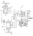
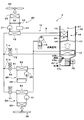
- FIG. 1 is an overall block diagram of an air conditioner in accordance with at least one embodiment of the present disclosure.
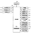
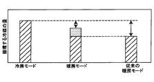
- FIG. 2 is a block diagram illustrating the electrical control of the air conditioner of at least one embodiment of the present disclosure. It is the graph which showed the quantity of the refrigerant which circulates through a frozen cycle device.
- BRIEF DESCRIPTION OF THE DRAWINGS It is a whole block diagram of the air conditioner which concerns on at least one embodiment of this indication.
- BRIEF DESCRIPTION OF THE DRAWINGS It is a whole block diagram of the air conditioner which concerns on at least one embodiment of this indication.
- BRIEF DESCRIPTION OF THE DRAWINGS It is a whole block diagram of the air conditioner which concerns on at least one embodiment of this indication.
- FIGS. 1 and 2 An air conditioner 1 equipped with a refrigeration cycle apparatus 10 according to a first embodiment of the present disclosure will be described using FIGS. 1 and 2.
- the air conditioner 1 shown in FIG. 1 is applied to a vehicle air conditioner.
- the air conditioning system for vehicles is an air conditioning system which adjusts a vehicle interior space to appropriate temperature.
- the air conditioner 1 of the present embodiment is mounted on a hybrid vehicle that obtains a driving force for vehicle traveling from an engine (in other words, an internal combustion engine) and a traveling electric motor.
- the hybrid vehicle of the present embodiment is configured as a plug-in hybrid vehicle capable of charging a battery (in other words, an on-board battery) mounted on the vehicle with electric power supplied from an external power supply (in other words, a commercial power supply) It is done.
- a battery in other words, an on-board battery
- an external power supply in other words, a commercial power supply
- a lithium ion battery can be used as the battery.
- the driving force output from the engine is used not only for driving the vehicle but also for operating the generator.
- the electric power generated by the generator and the electric power supplied from the external power supply can be stored in the battery, and the electric power stored in the battery is not only the electric motor for traveling but also the electric motor constituting the refrigeration cycle apparatus 10 It is supplied to various in-vehicle devices including formula components.
- the air conditioner 1 operates in a cooling mode for cooling the passenger compartment, which is an air conditioning target space (i.e., a cooling mode for cooling the air, which is a heat exchange target fluid), and a heating mode for heating the passenger compartment (i.e., heat exchange It is possible to switch between the operation of the heating mode for heating the air, which is the target fluid, and the operation.
- the air conditioner 1 includes a refrigeration cycle apparatus 10, a high temperature side heat medium flow passage 20, a low temperature side heat medium flow passage 30, and an indoor air conditioning unit 40.
- the refrigeration cycle apparatus 10 includes a compressor 11, an indoor condenser 12 (heat radiator), an outdoor condenser 13 (heat medium radiator), a pressure reducing valve 14 (pressure reducing portion), and an evaporator 15 in the refrigerant flow path 9.
- the accumulators 16 are arranged in this order.
- a fluorocarbon-based refrigerant is used as the refrigerant, and a subcritical refrigeration cycle in which the high-pressure refrigerant pressure does not exceed the critical pressure of the refrigerant is configured.
- the compressor 11 is an electric compressor driven by electric power supplied from a battery, and sucks, compresses and discharges the refrigerant of the refrigeration cycle apparatus 10. The operation of the compressor 11 is controlled by a control signal output from the controller 50.
- the refrigerant inlet side of the indoor condenser 12 is connected to the discharge port of the compressor 11.
- the indoor condenser 12 is disposed in a casing 41 of an indoor air conditioning unit 40 described later.
- the indoor condenser 12 exchanges heat between the high-temperature and high-pressure refrigerant (hereinafter, abbreviated as high-pressure refrigerant) discharged from the compressor 11 and the blast air, which is a heat exchange target fluid, at least in the heating mode. It is a radiator for heating which radiates heat to the blast air to heat the blast air. When the heat of the high pressure refrigerant is dissipated to the blast air, the high pressure refrigerant condenses.
- the refrigerant inlet side of the outdoor condenser 13 is connected to the refrigerant outlet side of the indoor condenser 12.
- the outdoor condenser 13 is disposed outside the vehicle.
- the outdoor condenser 13 exchanges heat between the high-pressure refrigerant flowing out of the indoor condenser 12 and the coolant, which is the high-temperature side heat medium flowing in the high-temperature side heat medium flow passage 20, at least in the cooling mode. It is a radiator for heat medium which radiates the heat which it has to cooling water.
- the cooling water flowing in the high temperature side heat medium flow passage 20 and the cooling water flowing in the low temperature side heat medium flow passage 30 described later use a liquid containing at least ethylene glycol, dimethylpolysiloxane or nanofluid, or an antifreeze liquid It is done.
- the high temperature side heat medium flow passage 20 is an annular flow passage for circulating the cooling water between the outdoor condenser 13 and the high temperature side radiator 22 described later.
- the outdoor condenser 13 the heating device 24, the high temperature side three-way valve 23, the high temperature side radiator 22, and the high temperature side pump 21 are arranged in this order.
- the high temperature side pump 21 circulates the cooling water in the high temperature side heat medium flow path 20 by sucking the cooling water and discharging it to the outdoor condenser 13 side.
- the high temperature side pump 21 is an electric pump, and is a high temperature side flow rate adjustment unit that adjusts the flow rate of the cooling water circulating in the high temperature side heat medium flow passage 20.
- the high temperature side radiator 22 exchanges heat between the cooling water and the outside air blown from the high temperature side blower 26. That is, in the high temperature side radiator 22, the cooling water heated by the outdoor condenser 13 exchanges heat with the outside air and is cooled.
- the high temperature side blower 26 is an electric blower which drives a fan by an electric motor, and its operation is controlled by a control signal output from the control device 50.
- the high temperature side radiator 22 and the high temperature side blower 26 are disposed on the front side in the vehicle bonnet. Therefore, the traveling wind can be applied to the high temperature side radiator 22 when the vehicle travels.
- the high temperature side heat medium flow passage 20 is provided with a high temperature side bypass flow passage 25 for circulating the cooling water discharged by the high temperature side pump 21 by bypassing the high temperature side radiator 22.
- the inlet side of the high temperature side bypass flow passage 25 is connected to the inlet side of the high temperature side radiator 22.
- the outlet side of the high temperature side bypass flow passage 25 is connected to the outlet side of the high temperature side radiator 22.
- the high temperature side three-way valve 23 is a high temperature side adjusting valve that adjusts the flow rate of the cooling water flowing into the high temperature side radiator 22 by adjusting the flow rate of the cooling water flowing into the high temperature side bypass flow passage 25.
- the operation of the high temperature side three-way valve 23 is controlled by a control signal output from the controller 50.
- the heating device 24 supplies heat to the cooling water of the high temperature side heat medium flow passage 20.
- a heating device 24 an on-vehicle device with heat generation at the time of operation, a PTC heater (electrical heater) that generates heat by being supplied with power, or the like can be adopted. More specifically, a battery, an inverter that is a frequency conversion unit, and a traveling electric motor that outputs a driving force for traveling can be adopted as the on-vehicle device. These on-vehicle devices are cooled by radiating heat to the cooling water of the high temperature side heat medium flow passage 20.
- the refrigerant inlet side of the pressure reducing valve 14 is connected to the refrigerant outlet side of the outdoor condenser 13.
- the pressure reducing valve 14 is a pressure reducing unit that reduces the pressure and expands the liquid phase refrigerant flowing out of the outdoor condenser 13. That is, the pressure reducing valve 14 reduces the pressure of the refrigerant on the downstream side of the indoor condenser 12 and the outdoor condenser 13.
- the pressure reducing valve 14 is an electric variable throttle mechanism whose operation is controlled by a control signal output from the control device 50, and includes a valve body and an electric actuator.
- the valve body is configured to be capable of changing the passage opening degree of the refrigerant passage (in other words, the throttle opening degree).
- the electric actuator has a stepping motor that changes the throttle opening of the valve body.
- the refrigerant inlet side of the evaporator 15 is connected to the refrigerant outlet side of the pressure reducing valve 14.
- the evaporator 15 evaporates the low pressure refrigerant by heat exchange between the heat of the low pressure refrigerant decompressed by the pressure reducing valve 14 and the cooling water which is the low temperature side heat medium flowing through the low temperature side heat medium channel 30.
- the low-pressure refrigerant absorbs heat from the cooling water and evaporates, whereby the cooling water is cooled.
- the low temperature side heat medium flow channel 30 is an annular flow channel, and cooling water which is a low temperature side heat medium circulates.
- the evaporator 15, the low temperature side pump 31, the cooler core channel three-way valve 32, and the low temperature side radiator 33 are arranged in this order of arrangement.
- the low temperature side pump 31 is a heat medium pump which sucks in and discharges the cooling water.
- the low temperature side pump 31 is an electric pump, and is a low temperature side flow rate adjustment unit that adjusts the flow rate of the cooling water circulating in the low temperature side heat medium flow passage 30.
- a cooler core flow channel 34 for circulating the cooling water which is the low temperature side heat medium discharged by the low temperature side pump 31 by bypassing the low temperature side radiator 33. Both ends of the cooler core flow passage 34 are connected to the low temperature side heat medium flow passage 30 on the inflow side and the outflow side of the low temperature side radiator 33.
- the cooler core flow path three-way valve 32 is a cooler core flow control valve that adjusts the flow rate of the cooling water flowing into the low temperature side radiator 33 by adjusting the flow rate of the cooling water as the low temperature side heat medium flowing into the cooler core flow path 34 is there.
- the operation of the cooler core flow path three-way valve 32 is controlled by a control signal output from the controller 50.
- the low temperature side radiator 33 exchanges heat between the cooling water as the low temperature side heat medium and the outside air blown from the low temperature side fan 36. Therefore, the cooling water cooled by the evaporator 15 is allowed to flow into the low temperature side radiator 33 to exchange heat with the outside air, whereby the low temperature cooling water can absorb heat from the outside air.
- the low temperature side fan 36 blows the outside air toward the low temperature side radiator 33.
- the low temperature side fan 36 is an electric fan that drives a fan by an electric motor, and its operation is controlled by a control signal output from the controller 50.
- the low temperature side radiator 33 and the low temperature side blower 36 are disposed on the front side in the vehicle bonnet, similarly to the high temperature side radiator 22 and the high temperature side blower 26. Therefore, the traveling wind can be applied to the low temperature side radiator 33 when the vehicle travels.
- the cooler core 35 exchanges heat between the cooling water of the low temperature side heat medium flow passage 30 and the blowing air which is a heat exchange target fluid blown into the vehicle compartment. Therefore, blowing air can be cooled by causing the cooling water cooled by the evaporator 15 to flow into the cooler core 35. That is, in the evaporator 15 according to the present embodiment, the heat of the blown air can be absorbed by the refrigerant decompressed by the pressure reducing valve 14 through the cooling water, and the refrigerant can be evaporated.
- the refrigerant inlet side of the accumulator 16 is connected to the refrigerant outlet side of the evaporator 15. That is, the accumulator 16 is provided between the evaporator 15 and the compressor 11, that is, on the upstream side of the compressor 11.
- the accumulator 16 is a gas-liquid separation unit that separates gas and liquid of the refrigerant that has flowed into the inside, and is a liquid storage unit that stores excess refrigerant in the cycle.
- the suction port side of the compressor 11 is connected to the gas phase refrigerant outlet of the accumulator 16. Therefore, the accumulator 16 suppresses the suction of the liquid-phase refrigerant into the compressor 11 and functions to prevent the liquid compression in the compressor 11.
- the required refrigerant flow rate for circulating the cycle in the cooling mode is larger than the required refrigerant flow rate for circulating the cycle in the heating mode. Therefore, in the heating mode, the surplus liquid phase refrigerant in the cycle is stored to absorb the fluctuation of the required refrigerant flow rate.
- the indoor air conditioning unit 40 is for blowing out the blowing air whose temperature has been adjusted by the refrigeration cycle apparatus 10 into the vehicle interior which is the space to be air conditioned.
- the indoor air conditioning unit 40 is disposed inside the instrument panel at the foremost part of the vehicle interior.
- the indoor air conditioning unit 40 is configured by housing the cooler core 35, the indoor condenser 12 and the like in a casing 41 forming the outer shell thereof.
- the casing 41 is an air passage forming portion that forms an air passage for blowing air blown into the vehicle compartment, which is a space to be air conditioned.
- the casing 41 has a certain degree of elasticity and is formed of a resin (for example, polypropylene) which is excellent in strength.
- Inside / outside air switching as an inside / outside air switching unit to switch and introduce inside air (air within the air conditioned space) and outside air (air outside the air conditioned space) into the casing 41 on the most upstream side of the air flow inside the casing 41 A device 43 is arranged.
- the inside / outside air switching device 43 is formed with an inside air introduction port 43 b for introducing inside air into the casing 41 and an outside air introduction port 43 c for introducing outside air into the casing 41.
- an inside / outside air switching door 43a is provided in the inside / outside air switching device 43 so as to be able to swing.
- the inside / outside air switching door 43a is driven by an electric actuator whose operation is controlled by a control signal output from the control device 50.
- the inside / outside air switching device 43 switches between the outside air mode and the inside air mode by means of the inside / outside air switching door 43a.
- the outside air mode is a mode in which the inside air introduction port 43b is closed by the inside / outside air switching door 43a and the outside air introduction port 43c is opened to introduce outside air which is air outside the space to be air conditioned into the casing 41.
- the inside air mode is a mode in which the outside air introduction port 43c is closed by the inside / outside air switching door 43a and the inside air introduction port 43b is opened to introduce inside air, which is air in the space to be air conditioned, into the casing 41.
- the inside / outside air switching device 43 continuously adjusts the opening areas of the inside air introduction port 43b and the outside air introduction port 43c by the inside / outside air switching door 43a, and the ratio of the inside air flow rate to the outside air flow rate is continuous. Can be changed to
- an air conditioning blower 42 for directing the air drawn in via the inside / outside air switching device 43 into the space to be air-conditioned is arranged.
- the air conditioning blower 42 is an electric blower that drives a centrifugal multi-blade fan (sirocco fan) by an electric motor, and the number of rotations (air flow amount) is controlled by the control voltage output from the control device 50.
- the cooler core 35 is disposed downstream of the air flow of the air conditioning blower. Further, the downstream side of the cooler core 35 of the air passage formed in the casing 41 is bifurcated, and the indoor condenser passage 45 and the cold air bypass passage 46 are formed in parallel.
- the indoor condenser 12 is disposed in the indoor condenser passage 45. That is, the indoor condenser passage 45 is an air passage for circulating the blown air which exchanges heat with the refrigerant in the indoor condenser 12.
- the cooler core 35 and the indoor condenser 12 are disposed in this order with respect to the flow of the blowing air. In other words, the cooler core 35 is disposed upstream of the indoor condenser 12 in the flow of the blown air.
- the indoor condenser passage 45 constitutes a part of an air passage through which the blown air flows in the order of the cooler core 35 ⁇ the indoor condenser 12.
- the cold air bypass passage 46 is an air passage that causes the blown air that has passed through the cooler core 35 to bypass the indoor condenser 12 and flow downstream.
- the air flow downstream of the cooler core 35 and the air flow upstream of the indoor condenser 12 is controlled by the control signal output from the control device 50 so that the indoor condenser of the air after passing through the cooler core 35
- An air mix door 44 is disposed to adjust the air volume ratio for passing 12.
- a mixing channel 47 is formed in the casing 41 on the downstream side of the merging portion of the indoor condenser passage 45 and the cold air bypass passage 46. In the mixing flow path 47, the blast air heated in the indoor condenser 12 and the blast air not heated in the indoor condenser 12 passing through the cold air bypass passage 46 are mixed.
- a plurality of opening holes are disposed for blowing the air (air-conditioned air) mixed in the mixing space into the vehicle compartment as the air-conditioned space.
- the face opening hole is an opening hole for blowing the conditioned air toward the upper body of the passenger in the vehicle room which is the space to be conditioned.
- the foot opening hole is an opening hole for blowing the conditioned air toward the feet of the occupant.
- the defroster opening hole is an opening hole for blowing the conditioned air toward the inner side surface of the vehicle front windshield.
- the temperature of the conditioned air mixed in the mixing space is adjusted by adjusting the air volume ratio between the air volume passing the indoor condenser 12 and the air volume passing the cold air bypass passage 46 by the air mix door 44.
- the temperature of the conditioned air blown out from the outlets into the vehicle room which is the space to be conditioned is adjusted.
- the air mix door 44 functions as a temperature control unit that adjusts the temperature of the conditioned air blown into the vehicle compartment, which is the space to be conditioned.
- the air mix door 44 has an electric actuator for driving the air mix door. The operation of the electric actuator is controlled by a control signal output from the controller 50.
- the electric actuator for driving the air mix door displaces the air mix door 44 so as to open the indoor condenser passage 45 and close the cold air bypass passage 46, the air which has passed through the cooler core 35 is sent to the indoor condenser 12.
- the air can be blown, and the heat of the high-pressure refrigerant can be dissipated to the blowing air in the indoor condenser 12.
- the air mix door 44 functions as a heat release amount adjustment unit that adjusts the amount of heat release that the high pressure refrigerant releases to the blowing air in the indoor condenser 12.
- a defroster door (not shown) for adjusting the opening area is arranged.
- These face door, foot door, and defroster door constitute an outlet mode switching door for switching the outlet mode.
- the face door, the foot door, and the defroster door are each connected to an electric actuator for driving the air outlet mode door via a link mechanism or the like, and are rotationally operated in conjunction with each other.
- the operation of the electric actuator is also controlled by a control signal output from the control device 50.
- the air outlet mode switched by the air outlet mode switching door includes a face mode, a bi-level mode, a foot mode and the like.
- the face mode is an outlet mode in which the face outlet is fully opened and blowing air is blown from the face outlet toward the upper body of the vehicle occupant.
- the bi-level mode is an air outlet mode in which both the face air outlet and the foot air outlet are opened to blow air toward the upper body and the foot of the passenger in the vehicle compartment.
- the foot mode is an outlet mode in which the air outlet is blown out from the foot outlet toward the foot of the passenger in the passenger compartment with the foot outlet fully open.
- the occupant manually operates the air outlet mode switching switch provided in the operation unit 60 shown in FIG. 2 to fully open the defroster air outlet and blow air from the defroster air outlet onto the inner surface of the vehicle windshield. It can also be done.
- the control device 50 shown in FIG. 2 is composed of a known microcomputer including a CPU, a ROM, a RAM and the like, and peripheral circuits thereof.
- the control device 50 performs various operations and processing based on the control program stored in the ROM.
- Various control target devices are connected to the output side of the control device 50.
- the control device 50 is a control unit that controls the operation of various control target devices.
- the control target devices controlled by the control device 50 include the compressor 11, the pressure reducing valve 14, the high temperature side pump 21, the high temperature side three-way valve 23, the high temperature side blower 26, the low temperature side pump 31, the cooler core flow path three way valve 32, the low temperature side
- the control device 50 is integrally configured with a control unit that controls various control target devices connected to the output side.
- operation of each control object apparatus among the control apparatuses 50 comprises the control part which controls the action
- the software and hardware which control the air mix door 44 among the control apparatuses 50 are the heat release amount control part 60a.
- control sensor groups such as an inside air temperature sensor 51, an outside air temperature sensor 52, and a solar radiation amount sensor 53 are connected to the input side of the control device 50.
- the inside air temperature sensor 51 detects a vehicle interior temperature Tr.
- the outside air temperature sensor 52 detects an outside air temperature Tam.
- the solar radiation amount sensor 53 detects the solar radiation amount Ts in the vehicle compartment.
- An operation unit 60 is connected to the input side of the control device 50.
- the operating unit 60 is operated by the occupant.
- the operation unit 60 is disposed in the vicinity of an instrument panel at the front of the vehicle interior.
- An operation signal from the operation unit 60 is input to the control device 50.
- the operation unit 60 is provided with an air conditioner switch, a temperature setting switch, and the like.
- the air conditioner switch sets whether to cool the blowing air in the indoor air conditioning unit.
- the temperature setting switch sets the set temperature of the vehicle interior.
- control device 50 Based on the detection signal detected by the control sensor group and the operation signal from operation unit 60, control device 50 calculates target blowout temperature TAO of the air to be blown into the vehicle compartment. Then, the operation mode is switched based on the target blowout temperature TAO and the like. Furthermore, in the present embodiment, the heating mode is switched to the extremely low temperature mode when the outside temperature is lower than or equal to a predetermined reference outside temperature. Each operation mode will be described below.
- the control device 50 determines the operation states (control signals to be output to various control devices) of the various control target devices based on the detection signal and the target blowing temperature TAO and the like. Specifically, the control device 50 operates the compressor 11, the high temperature side pump 21, and the low temperature side pump 31 so as to exert the discharge capacity in the predetermined cooling mode. The control device 50 determines a control signal to be output to the pressure reducing valve 14 so as to have a predetermined throttle opening degree for the cooling mode.
- the control device 50 closes the high temperature side bypass flow passage 25 and controls the operation of the high temperature side three-way valve 23 so that the coolant flows into the high temperature side radiator 22.
- the controller 50 opens the cooler core flow passage 34 and controls the operation of the cooler core flow passage three-way valve 32 so that the cooling water flows into the cooler core 35.
- control device 50 closes the indoor condenser passage 45 (state shown by the solid line in FIG. 1), and the air mix door 44 so that the total flow rate of the blown air passing through the cooler core 35 flows into the cold air bypass passage 46. Control the operation of the
- the high pressure refrigerant discharged from the compressor 11 flows into the indoor condenser 12.
- the air mix door 44 is displaced so as to allow the blown air to flow into the cold air bypass passage 46. Therefore, the high-pressure refrigerant that has flowed into the indoor condenser 12 flows out of the indoor condenser 12 with little heat release to the blown air.
- the high temperature side three-way valve 23 is switched to flow the cooling water into the high temperature side radiator 22. Therefore, the high pressure refrigerant flowing into the outdoor condenser 13 dissipates heat to the cooling water cooled by the high temperature side radiator 22 and condenses. Thereby, the heat which the high pressure refrigerant has in the outdoor condenser 13 is absorbed by the cooling water.
- the heat release amount of the high pressure refrigerant in the indoor condenser 12 is smaller than the heat release amount of the high pressure refrigerant in the outdoor condenser 13.
- the pressure reducing valve 14 is in a squeezed state in which the pressure reducing valve 14 exerts a pressure reducing function, the refrigerant flowing into the pressure reducing valve 14 is reduced in pressure to be a low pressure refrigerant.
- the pump 31 is operating. Therefore, the low pressure refrigerant flowing into the evaporator 15 absorbs heat from the cooling water circulating in the low temperature side heat medium flow passage 30 and evaporates. Thereby, the cooling water circulating in the low temperature side heat medium channel 30 is cooled.
- the cooler core flow path three-way valve 32 is switched to flow the cooling water into the cooler core 35. Therefore, the cooling water cooled by the evaporator 15 exchanges heat with the blowing air at the cooler core 35 and absorbs heat. Thereby, the blowing air is cooled.
- the refrigerant flowing out of the evaporator 15 flows into the accumulator 16 to be separated into gas and liquid.
- the gas phase refrigerant separated by the accumulator 16 is sucked into the compressor 11 and compressed again.
- the blowing air cooled by the cooler core 35 can be blown into the vehicle compartment. Thereby, cooling of the vehicle interior can be realized.
- the control device 50 determines the operation states (control signals to be output to various control devices) of the various control target devices based on the detection signal and the target blowout temperature TAO and the like. Specifically, the control device 50 operates the compressor 11, the high temperature side pump 21, and the low temperature side pump 31 so as to exert the discharge capacity in the predetermined heating mode. The control device 50 determines a control signal to be output to the pressure reducing valve 14 so as to have a predetermined throttle opening degree for the heating mode.
- the control device 50 closes the high temperature side bypass flow passage 25 and controls the operation of the high temperature side three-way valve 23 so that the coolant flows into the high temperature side radiator 22.
- the controller 50 closes the cooler core flow passage 34 and controls the operation of the cooler core flow passage three-way valve 32 so that the cooling water flows into the low temperature side radiator 33.
- the controller 50 closes the cold air bypass passage 46 (the state shown by the broken line in FIG. 1), and the air mix door 44 allows the entire flow of the blown air passing through the cooler core 35 to flow into the indoor condenser passage 45. Control the operation of the Therefore, in the heating mode, the flow rate of the blown air flowing into the indoor condenser 12 is higher than in the cooling mode. In other words, in the cooling mode, the flow rate of the blown air flowing into the indoor condenser 12 is smaller than in the heating mode.
- the high pressure refrigerant discharged from the compressor 11 flows into the indoor condenser 12.
- the air mix door 44 is displaced so as to allow the blown air to flow into the indoor condenser passage 45. Therefore, the high-pressure refrigerant flowing into the indoor condenser 12 releases heat to the blown air and condenses. Thereby, the blowing air which flows through the indoor condenser passage 45 is heated.
- the high temperature side three-way valve 23 is switched to flow the cooling water into the high temperature side radiator 22. Therefore, the high-pressure refrigerant flowing into the outdoor condenser 13 further radiates heat to the cooling water cooled by the high temperature side radiator 22 and condenses, as in the cooling mode. Thereby, the heat which the high pressure refrigerant has in the outdoor condenser 13 is absorbed by the cooling water.
- the heat release amount of the high pressure refrigerant in the indoor condenser 12 is larger than the heat release amount of the high pressure refrigerant in the outdoor condenser 13. Therefore, in the heating mode, the dryness of the high pressure refrigerant on the inlet side of the outdoor condenser 13 is smaller than that in the cooling mode.
- the heat release amount of the high-pressure refrigerant in the indoor condenser 12 increases more than in the cooling mode.
- the heat release amount of the high-pressure refrigerant in the indoor condenser 12 is smaller than in the heating mode.
- the high pressure refrigerant flowing out of the outdoor condenser 13 is reduced in pressure by the pressure reducing valve 14 to be a low pressure refrigerant, as in the cooling mode.
- the low pressure refrigerant reduced in pressure by the pressure reducing valve 14 flows into the evaporator 15.
- the low temperature side pump 31 is operating. Therefore, the low pressure refrigerant flowing into the evaporator 15 absorbs heat from the cooling water circulating in the low temperature side heat medium flow passage 30 and evaporates. Thereby, the cooling water circulating in the low temperature side heat medium channel 30 is cooled.
- the cooler core flow path three-way valve 32 is switched so as to allow the coolant to flow into the low temperature side radiator 33. Therefore, the cooling water cooled by the evaporator 15 exchanges heat with the outside air in the low temperature side radiator 33 and is heated. The refrigerant flowing out of the evaporator 15 flows into the accumulator 16 to be separated into gas and liquid. The gas phase refrigerant separated by the accumulator 16 is sucked into the compressor 11 and compressed again.
- the blowing air heated by the indoor condenser 12 can be blown out into the vehicle compartment. Thereby, heating of the vehicle interior can be realized. Furthermore, the refrigerant can be condensed by the outdoor condenser 13 and the condensed refrigerant can be retained in the outdoor condenser 13.
- the control device 50 determines the operation states (control signals to be output to the various control devices) of the various control target devices, as in the heating mode. In the low temperature heating mode, the control device 50 opens the high temperature side bypass flow passage 25 and controls the operation of the high temperature side three-way valve 23 so that the cooling water bypasses the high temperature side radiator 22.
- the high pressure refrigerant discharged from the compressor 11 flows into the indoor condenser 12.
- the air mix door 44 is displaced so as to allow the blown air to flow into the indoor condenser passage 45. Therefore, the high-pressure refrigerant flowing into the indoor condenser 12 releases heat to the blown air and condenses. Thereby, the blowing air which flows through the indoor condenser passage 45 is heated.
- the temperature of the blowing air flowing into the indoor condenser 12 is low. Therefore, the high pressure refrigerant flowing into the indoor condenser 12 becomes a liquid phase refrigerant having a degree of subcooling.
- the high-pressure refrigerant flowing out of the indoor condenser 12 flows into the outdoor condenser 13.
- the high temperature side three-way valve 23 is switched to flow the cooling water into the high temperature side bypass flow passage 25. Therefore, the high pressure refrigerant flowing into the outdoor condenser 13 is heated by the cooling water heated by the heating device 24.
- the subsequent operation is similar to the heating mode.
- the blowing air heated by the indoor condenser 12 can be blown out into the vehicle compartment. Thereby, heating of the vehicle interior can be realized. Furthermore, the refrigerant can be heated by the outdoor condenser 13 to raise the high pressure side refrigerant pressure of the cycle. Therefore, the refrigerant condensation temperature in the indoor condenser 12 can be raised to efficiently raise the temperature of the blown air.
- the air mix door 44 which is the adjustment unit for heat release causes the amount of heat release in the indoor condenser 12 to be larger than the amount of heat release in the outdoor condenser 13.
- the air mix door 44 reduces the heat release amount in the indoor condenser 12 more than in the heating mode.
- the refrigerant circuit of the refrigeration cycle apparatus 10 does not need to be switched, and the heating mode is It is possible to switch between the cooling mode.
- the heating mode can be realized by increasing the heat release amount in the indoor condenser 12 and heating the blowing air in the indoor condenser 12, reducing the heat release amount in the indoor condenser 12, and
- the cooling mode can be realized by cooling the blowing air by the heat absorption function of the refrigerant.
- the pressure adjustment valve and the switching valve for switching the refrigerant circuit according to the operation mode become unnecessary.
- the cycle configuration of the refrigeration cycle apparatus 10 can be simplified, and complicated control for switching the refrigerant circuit of the cycle apparatus 10 is not necessary.
- the air mix door 44 makes the dryness of the refrigerant on the inlet side of the outdoor condenser 13 smaller than that in the cooling mode. Thereby, the refrigerant of the liquid phase can be retained in the outdoor condenser 13 in the heating mode.
- the required refrigerant flow rate for circulating the cycle in the cooling mode is larger than the required refrigerant flow rate for circulating the cycle in the heating mode.
- the outdoor condenser 13 can store the condensed refrigerant.
- the minimum required capacity of the accumulator 16 can be reduced as compared with the conventional refrigeration cycle apparatus, and hence the capacity of the accumulator 16 can be reduced.
- the accumulator 16 can be miniaturized.
- the indoor condenser 12 and the outdoor condenser are arranged to absorb all the fluctuation of the amount of refrigerant circulating in the refrigeration cycle apparatus 10 in the outdoor condenser 13.
- the accumulator 16 can be eliminated if the amount of heat release at 13 is adjusted.
- the refrigeration cycle apparatus 10 can be further miniaturized, and the manufacturing cost of the refrigeration cycle apparatus 10 can be reduced.
- the air mix door 44 adjusts the flow rate of the blowing air passing through the indoor condenser 12. Then, in the cooling mode, the air mix door 44 reduces the flow rate of the blowing air passing through the indoor condenser 12 more than in the heating mode. As a result, it is possible to easily configure a heat release amount adjustment unit that adjusts the amount of heat release from the high pressure refrigerant in the indoor condenser 12 to the blown air.
- the heating device 24 heats the high pressure refrigerant flowing out of the indoor condenser 12 in the heating at the very low temperature mode.
- the high pressure side refrigerant pressure of the refrigeration cycle apparatus 10 can be raised. Therefore, the refrigerant condensation temperature in the indoor condenser 12 can be raised to efficiently raise the temperature of the blowing air, and the heating performance of the air conditioner 1 can be improved.
- the heating device 24 is disposed in the high temperature side heat medium flow passage 20, and heats the high pressure refrigerant by heating the cooling water.
- the high pressure refrigerant can be heated in the extremely low temperature heating mode with a simple configuration.
- the heating device 24 is a vehicle-mounted device, the high-pressure refrigerant can be heated by the exhaust heat of the vehicle-mounted device, so energy for heating the high-pressure refrigerant becomes unnecessary.
- the high temperature side heat medium flow channel 20 of the present embodiment has a high temperature side radiator 22, a high temperature side bypass flow channel 25, and a high temperature side three-way valve 23. According to this, even when it is difficult to adjust the heating capacity as in the case where an on-vehicle device is adopted as the heating device 24, it is possible to easily adjust the amount of heating of the cooling water.
- the low temperature side radiator 33 for cooling the heat exchange with the outside air by cooling the cooling water, and the low temperature side heat medium for circulating the cooling water between the evaporator 15 and the low temperature side radiator 33
- a flow path 30 and a low temperature side pump 31 which discharges the cooling water and circulates the cooling water in the low temperature side heat medium flow path 30 are provided.
- the cooling water circulating through the low temperature side heat medium flow passage 30 is heated in heat exchange with the outside air in the low temperature side radiator 33, and heat is absorbed by the low pressure refrigerant in the evaporator 15 be able to.
- the cooling water discharged by the low temperature side pump 31 is connected to the low temperature side heat medium flow channel 30 at both ends on the inflow side and the outflow side of the low temperature side radiator 33.
- a cooler core flow path 34 is provided to bypass the low temperature side radiator 33 for circulation.
- a cooler core 35 is disposed which causes heat to be exchanged between the cooling water and the blowing air so that the heat contained in the blowing air is absorbed by the cooling water.
- a cooler core flow path three-way valve 32 is disposed in the low temperature side heat medium flow path 30 for adjusting the flow rate of the cooling water flowing into the cooler core flow path 34 and the flow rate of the cooling water flowing into the low temperature side radiator 33 .
- the cooler core flow path three-way valve 32 opens the cooler core flow path 34 and closes the flow path on the inflow side of the low temperature side radiator 33 of the low temperature side heat medium flow path 30. Is circulated, and the cooled air flowing through the casing 41 can be cooled by the cooler core 35.
- the cooler core flow path three-way valve 32 closes the cooler core flow path 34 and opens the low temperature side heat medium flow path 30 on the inflow side of the low temperature side radiator 33.
- the air does not flow, and the blown air flows into the indoor condenser 12 without being cooled by the cooler core 35. Therefore, in the heating mode, the blown air is prevented from being unnecessarily cooled by the cooler core 35, and the heating capacity of the air conditioner 1 can be improved.
- the indoor condenser 12 exchanges heat between the high pressure refrigerant and the blowing air to heat the blowing air. According to this, since the heat of the high pressure refrigerant can be dissipated directly to the blast air, for example, the heat of the high pressure refrigerant can be indirectly dissipated to the blast air through the heat medium or the like. Thus, the heating capacity of the blown air of the refrigeration cycle apparatus 10 can be improved.
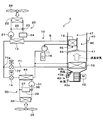
- FIG. 4 The refrigeration cycle apparatus 10 of the air conditioner 2 of the second embodiment is obtained by adding a refrigerant bypass flow passage 17 and a refrigerant three-way valve 18 to the air conditioner 1 of the first embodiment.
- the other configuration is the same as the air conditioner 1 of the first embodiment.
- the refrigerant bypass flow passage 17 is a flow passage that causes the high-pressure refrigerant discharged by the compressor 11 to flow around the indoor condenser 12 to the outdoor condenser 13.
- the refrigerant bypass flow path 17 is connected to the inflow side and the outflow side of the indoor condenser 12 of the refrigerant flow path 9.
- the refrigerant three-way valve 18 adjusts the flow rate of the high pressure refrigerant flowing into the refrigerant bypass flow path 17 to thereby control the flow rate of the high pressure refrigerant flowing into the indoor condenser 12 among the high pressure refrigerant discharged from the compressor 11 It is a flow control valve that adjusts the flow rate of the high pressure refrigerant flowing into the outdoor condenser 13 among the high pressure refrigerant discharged from 11.
- the refrigerant three-way valve 18 can adjust the amount of heat released from the high pressure refrigerant in the indoor condenser 12 to the blast air by adjusting the flow rate of the high pressure refrigerant flowing into the indoor condenser 12. Therefore, the refrigerant three-way valve 18 of the present embodiment functions as a heat release amount adjustment unit that adjusts the amount of heat release from the high pressure refrigerant to the blown air in the indoor condenser 12.
- the refrigerant three-way valve 18 reduces the flow rate of the high-pressure refrigerant flowing into the indoor condenser 12 more than the heating mode (including the cryogenic temperature heating mode).
- the refrigerant three-way valve 18 closes the refrigerant bypass flow passage 17 and opens the inflow side of the indoor condenser 12.
- the entire amount of the high pressure refrigerant discharged by the compressor 11 flows into the indoor condenser 12, and in the indoor condenser 12, the high pressure refrigerant and the blowing air exchange heat to heat the blowing air.
- the refrigerant three-way valve 18 opens the refrigerant bypass flow passage 17 and closes the inflow side of the indoor condenser 12.
- the entire amount of the high-pressure refrigerant discharged by the compressor 11 flows into the refrigerant bypass flow path 17 and flows into the outdoor condenser 13.
- the flow rate of the high-pressure refrigerant flowing into the indoor condenser 12 is adjusted by the refrigerant three-way valve 18, and the high-pressure refrigerant in the indoor condenser 12 is discharged to the blowing air.
- the amount of heat it is possible to switch between the heating mode and the cooling mode. Therefore, the same effect as that of the first embodiment can be obtained.
- FIG. 5 In the air conditioner 3 of the third embodiment, a branching portion 71a, a refrigerant flow path 71 for cooling, a pressure reducing valve 72 for cooling, an indoor evaporator 73, and the like are added to the air conditioner 1 of the first embodiment.
- the road three-way valve 32, the cooler core flow passage 34, the cooler core 35 and the like are eliminated.
- the branch part 71a is a part which branches the flow of the refrigerant
- the inlet side of the pressure reducing valve 14 is connected to one outlet of the branch portion 71a.
- the inlet side of the cooling pressure reducing valve 72 is connected to the other outlet of the branch portion 71a. For this reason, the pressure reducing valve 14 and the cooling pressure reducing valve 72 are disposed in parallel to the refrigerant flow.
- the cooling refrigerant channel 71 is a refrigerant passage that connects one outlet of the branch portion 71a and the suction side of the compressor 11 (specifically, the inlet side of the accumulator 16).
- a cooling pressure-reduction valve 72 and an indoor evaporator 73 are arranged in this order from the side of the branch portion 71a.
- the cooling pressure reducing valve 72 is a pressure reducing portion that decompresses and expands the refrigerant branched by the branching portion 71 a at least in the cooling mode.
- the cooling pressure reducing valve 72 is an electric variable throttle mechanism whose operation is controlled by a control signal output from the controller 50.
- the cooling pressure reducing valve 72 has a valve body and an electric actuator.
- the valve body is configured to be capable of changing the passage opening degree of the refrigerant passage (in other words, the throttle opening degree).
- the electric actuator has a stepping motor that changes the throttle opening of the valve body.
- the indoor evaporator 73 is an evaporator that evaporates the low pressure refrigerant decompressed by the cooling pressure reducing valve 72 by directly absorbing the heat of the blown air, at least in the cooling mode.
- the indoor evaporator 73 is disposed on the air flow upstream side of the indoor condenser 12 and the air mix door 44 of the air passage formed in the casing 41.
- a heating evaporator 84 which exchanges heat between the low pressure refrigerant decompressed by the pressure reducing valve 14 and the cooling water which is a low temperature side heat medium circulating in the low temperature side heat medium channel 30. Is arranged.
- the basic configuration of the heating evaporator 84 is the same as the evaporator 15 described in the first embodiment.
- a low temperature side bypass flow channel 37, a low temperature side three-way valve 38, and a heat source device 39 are disposed in the low temperature side heat medium flow channel 30 of the present embodiment.
- the low temperature side bypass flow channel 37 is a flow channel that circulates the cooling water discharged by the low temperature side pump 31 by bypassing the low temperature side radiator 33.
- the low temperature side bypass passage 37 connects the low temperature side heat medium passage 30 on the inflow side of the low temperature side radiator 33 and the low temperature side heat medium passage 30 on the outflow side of the low temperature side radiator 33.
- the low temperature side three-way valve 38 adjusts the flow rate of the cooling water flowing into the low temperature side radiator 33 and the flow rate of the cooling water flowing into the heat source device 39 by adjusting the flow rate of the cooling water flowing into the low temperature side bypass passage 37 Low temperature side flow control valve.
- the operation of the low temperature side three-way valve 38 is controlled by a control signal output from the controller 50.
- the heat source device 39 can adopt a PTC heater (electrical heater) or the like that generates heat by being supplied with on-vehicle equipment that generates heat during operation or power.
- the structure of the other air conditioner 3 is the same as that of the air conditioner 1 of 1st Embodiment.
- the control device 50 closes the pressure reducing valve 14 and brings the cooling pressure reducing valve 72 into a throttle state in which the refrigerant pressure reducing function is exhibited.
- a target excess rate predetermined for the degree of subcooling of the refrigerant flowing into the cooling pressure reducing valve 72 approaches the maximum value of the coefficient of performance (so-called COP) of the cycle. It is determined to approach the degree of cooling.
- the operation of the other control target devices is the same as that of the cooling mode of the first embodiment.
- the refrigerant discharged from the compressor 11 dissipates heat in the outdoor condenser 13 as in the first embodiment. Since the pressure reducing valve 14 is closed, the refrigerant flowing out of the outdoor condenser 13 flows into the cooling pressure reducing valve 72 and is reduced in pressure to be a low pressure refrigerant.
- the low pressure refrigerant reduced in pressure by the pressure reducing valve 14 flows into the indoor evaporator 73.
- the low pressure refrigerant flowing into the indoor evaporator 73 absorbs heat from the air blown from the air conditioning blower 42 and evaporates. Thereby, the blowing air is cooled.
- the refrigerant flowing out of the indoor evaporator 73 flows into the accumulator 16 to be separated into gas and liquid.
- the gas phase refrigerant separated by the accumulator 16 is sucked into the compressor 11 and compressed again.
- the blowing air cooled by the indoor evaporator 73 can be blown into the vehicle compartment. Thereby, cooling of the vehicle interior can be realized.
- the controller 50 closes the cooling pressure reducing valve 72. Furthermore, the control device 50 controls the operation of the low temperature side three-way valve 38 so that the cooling water of the low temperature side heat medium flow passage 30 flows into the heat source device 39 side.
- the operation of the other control target devices is the same as the heating mode and the cryogenic temperature heating mode of the first embodiment.
- the refrigerant discharged from the compressor 11 dissipates heat in the indoor condenser 12 and the outdoor condenser 13 and is decompressed in the pressure reducing valve 14 as in the first embodiment. It becomes a low pressure refrigerant.
- the low pressure refrigerant reduced in pressure by the pressure reducing valve 14 flows into the heating evaporator 84.
- the low temperature side pump 31 is operating. Therefore, the low pressure refrigerant flowing into the heating evaporator 84 absorbs heat from the cooling water circulating in the low temperature side heat medium flow passage 30 and evaporates. Thereby, the cooling water circulating in the low temperature side heat medium channel 30 is cooled.
- the low temperature side three-way valve 38 is switched so that the cooling water flows into the heat source device 39 side. Therefore, the cooling water cooled by the heating evaporator 84 absorbs heat from the heat source device 39. Therefore, the low-pressure refrigerant flowing into the heating evaporator 84 evaporates by absorbing heat absorbed by the cooling water from the heat source device 39.
- the refrigerant flowing out of the heating evaporator 84 flows into the accumulator 16 to be separated into gas and liquid.
- the other operations are the same as in the first embodiment.
- the blowing air heated by the indoor condenser 12 can be blown out into the vehicle interior.
- heating of the vehicle interior can be realized.
- the refrigerant can be condensed by the outdoor condenser 13 and the condensed refrigerant can be retained in the outdoor condenser 13.
- the blowing air heated by the indoor condenser 12 can be blown out into the vehicle interior. Thereby, heating of the vehicle interior can be realized. Furthermore, as in the first embodiment, the refrigerant condensation temperature in the indoor condenser 12 can be raised to efficiently raise the temperature of the blowing air.
- the air mix door 44 serving as the heat dissipation adjustment unit blows the air of the heat possessed by the high pressure refrigerant in the indoor condenser 12 It is possible to switch between the heating mode and the cooling mode by adjusting the amount of heat released to. Therefore, the cycle configuration of the refrigeration cycle apparatus 10 can be simplified, and complicated control for switching the refrigerant circuit of the cycle apparatus 10 is not necessary.
- the refrigeration cycle apparatus 10 of the present embodiment includes the branch portion 71a, the heating evaporator 84, and the indoor evaporator 73. Therefore, in the cooling mode, since the blown air and the low pressure refrigerant can be directly subjected to heat exchange in the indoor evaporator 73, for example, the blown air and the low pressure refrigerant are indirectly heat exchanged via the heat medium or the like. With respect to the case where the cooling cycle device 10 is used, the cooling capacity of the blowing air of the refrigeration cycle apparatus 10 can be improved.
- the refrigerant flows from the coolant to the heating evaporator 84 by flowing the refrigerant into the heating evaporator 84 without flowing the refrigerant into the indoor evaporator 73.
- a heat source device 39 for heating the cooling water which is the low temperature side heat medium is disposed. Accordingly, heating of the vehicle interior can be realized using the heat generated by the heat source device 39.
- the low temperature side radiator 33 is disposed in the low temperature side heat medium flow passage 30 of the present embodiment. Therefore, in the heating mode and the cryogenic temperature heating mode of the present embodiment, an example in which the operation of the low temperature side three-way valve 38 is controlled so that the cooling water of the low temperature side heat medium passage 30 flows into the heat source device 39 will be described. However, the cooling water may be made to flow into both the heat source device 39 side and the low temperature side radiator 33 side.
- the refrigeration cycle apparatus 10 includes the indoor evaporator 73 and the heating evaporator 84 which are independent of each other as a heat exchanger for evaporating the low pressure refrigerant. Therefore, as the heating evaporator 84 and the indoor evaporator 73, ones of appropriate size and heat exchange type according to the respective applications can be adopted.
- a so-called tank-and-tube type heat exchanger structure is configured having a plurality of tubes for circulating the refrigerant and a pair of tanks for distributing or collecting the refrigerant to the tubes. You may use one.
- a so-called stacked heat exchanger structure formed by stacking and arranging plate members may be adopted.
- the air conditioner 4 of the fourth embodiment is different from the air conditioner 3 of the third embodiment in the evaporator flow path 81, the evaporator pressure reducing valve 82, the heat source device cooling evaporator 83, the heat source device cooling flow path 85, The heat source apparatus cooling pump 86 is added, and the low temperature side bypass passage 37 and the low temperature side three-way valve 38 are eliminated.
- the other configuration is the same as the air conditioner 3 of the third embodiment.
- the evaporator flow path 81 connects the refrigerant flow path 9 between the outdoor condenser 13 and the pressure reducing valve 14 and the refrigerant flow path 9 between the evaporator 15 and the accumulator 16 (compressor 11).
- the evaporator pressure reducing valve 82 and the heat source device cooling evaporator 83 are arranged in this order in the evaporator flow path 81 from the side of the branch portion 81 a of the refrigerant flow path 9 between the outdoor condenser 13 and the pressure reducing valve 14. It is arranged.
- the evaporator pressure reducing valve 82 is provided in parallel with the pressure reducing valve 14 and the cooling pressure reducing valve 72.
- the evaporator pressure reducing valve 82 is a pressure reducing portion that decompresses and expands the liquid phase refrigerant branched at the branch portion 81 a that has flowed out of the outdoor condenser 13.
- the evaporator pressure reducing valve 82 is an electric variable throttle mechanism whose operation is controlled by a control signal output from the control device 50, and includes a valve body and an electric actuator.
- the valve body is configured to be capable of changing the passage opening degree of the refrigerant passage (in other words, the throttle opening degree).
- the electric actuator has a stepping motor that changes the throttle opening of the valve body.
- the heat source apparatus cooling evaporator 83 is provided in parallel with the evaporator 15 and the indoor evaporator 73.
- the heat source apparatus cooling evaporator 83 exchanges heat between the heat of the low pressure refrigerant decompressed by the evaporator pressure reducing valve 82 and the cooling water as the low temperature side heat medium flowing through the heat source apparatus cooling flow path 85.
- the low pressure refrigerant is evaporated by absorbing the heat of the cooling water.
- the heat source device cooling flow passage 85 is an annular flow passage, through which cooling water, which is a low temperature side heat medium, circulates.
- a heat source device cooling evaporator 83, a heat source device cooling pump 86, and a heat source device 39 are arranged in this order of arrangement.
- the heat source apparatus cooling pump 86 is a heat medium pump that sucks in and discharges the cooling water.
- the heat source apparatus cooling pump 86 is an electric pump, and is a cooling water flow rate adjustment unit that adjusts the flow rate of the cooling water circulating through the heat source apparatus cooling flow path 85.
- the evaporator pressure reducing valve 82 When the heat source device 39 is cooled, the evaporator pressure reducing valve 82 is throttled. As a result, the low-pressure refrigerant reduced in pressure by the evaporator pressure reducing valve 82 flows into the heat source device cooling evaporator 83. Then, in the heat source apparatus cooling evaporator 83, the low pressure refrigerant exchanges heat with the cooling water and is heated, and the cooling water exchanges heat with the low pressure refrigerant and is cooled. Then, the heat source device 39 is cooled by the cooling water discharged by the heat source device cooling pump 86.
- the evaporator for evaporating the low pressure refrigerant is the indoor evaporator 73 in which the low pressure refrigerant decompressed by the cooling pressure reducing valve 72 absorbs heat of the blowing air in the cooling mode.
- the low pressure refrigerant decompressed by the evaporator pressure reducing valve 82 absorbs heat generated by the heat source device 39, and the low pressure refrigerant decompressed by the pressure reducing valve 14 in the heating mode is the outside air And a heating evaporator 84 for absorbing heat.
- application of refrigeration cycle device 10 concerning this indication is not limited to vehicles, but is a stationary air conditioner It may apply to Furthermore, application of the refrigeration cycle apparatus 10 according to the present disclosure is not limited to the air conditioner, and may be applied to a water heater in which the fluid to be heat-exchanged is drinking water or household water.
- a liquid storage part is not limited to this.
- a receiver may be disposed downstream of the outdoor condenser 13 to separate the gas and liquid of the refrigerant flowing out of the outdoor condenser and store the excess liquid phase refrigerant.
- the accumulator 16 and the receiver may be arranged at the same time.
- refrigeration cycle device 10 which can be switched to air conditioning mode and heating mode (including cryogenic temperature heating mode)
- change of the operation mode of refrigeration cycle device 10 is not limited to this.
- the air is cooled by the cooler core 35 as in the cooling mode.
- the opening degree of the air mix door 44 may be changed, and the blown air cooled and dehumidified by the cooler core 35 may be reheated by the indoor condenser 12 and blown out to the air conditioning target space. According to this, it can switch to the dehumidification heating mode which implement
- the heat of the heat source apparatus 39 is absorbed similarly to the heating mode. Further, the air mix door 44 is displaced so as to close the indoor condenser passage 45, and the high temperature side pump 21 is operated to flow the cooling water of the high temperature side heat medium flow passage 20 into the high temperature side radiator 22. According to this, it is possible to switch to the device cooling mode in which the heat generated by the heat source device 39 is released to the outside air by the high temperature side radiator 22 without adjusting the temperature of the blowing air.
- the high temperature side radiator 22 and the low temperature side radiator 33 may be configured such that the cooling water flowing through them (that is, the high temperature side heat medium and the low temperature side heat medium) can transfer heat.
- heat transfer is possible by configuring the high temperature side radiator 22 and the low temperature side radiator 33 with a tank-and-tube type heat exchanger, and configuring the fins for promoting heat exchange with both heat exchangers with a common metal member It may be Further, the high temperature side heat medium and the low temperature side heat medium may be merged.
- the evaporator 83 for heating a heat source device and the evaporator 84 for heating described in the fourth embodiment are a refrigerant and a heat medium (phases It is common in the point of a heat exchanger that exchanges heat with the unchanging liquid). Therefore, the heat source apparatus cooling evaporator 83 and the heating evaporator 84 may be integrated by adopting a common structure (for example, a laminated heat exchanger structure).
- Each component which comprises the refrigerating cycle apparatus 10 is not limited to what was disclosed by the above-mentioned embodiment.
- the above-mentioned embodiment explained the example which adopted an electric compressor as compressor 11, when applied to a vehicle travel engine, the vehicle travels via a pulley, a belt, etc. as compressor 11.
- An engine driven compressor driven by a rotational driving force transmitted from an engine may be employed.
Landscapes
- Engineering & Computer Science (AREA)
- Physics & Mathematics (AREA)
- Mechanical Engineering (AREA)
- Thermal Sciences (AREA)
- General Engineering & Computer Science (AREA)
- Chemical & Material Sciences (AREA)
- Combustion & Propulsion (AREA)
- Air-Conditioning For Vehicles (AREA)
Abstract
冷凍サイクル装置は、圧縮機(11)と、加熱用放熱器(12)と、熱媒体用放熱器(13)と、減圧部(14)と、蒸発器(15、73)と、放熱量調整部(44、18)と、を有する。加熱用放熱器は、高圧冷媒の有する熱を熱交換対象流体に放熱させる。熱媒体用放熱器は、高圧冷媒の有する熱を高温側熱媒体に放熱させる。減圧部は、加熱用放熱器及び熱媒体用放熱器の下流側の冷媒を減圧させる。蒸発器は、減圧部にて減圧された冷媒を、熱交換対象流体の有する熱を吸熱させることによって蒸発させる。放熱量調整部は、加熱用放熱器にて高圧冷媒が熱交換対象流体へ放熱する放熱量を調整する。放熱量調整部は、熱交換対象流体を加熱する加熱モードでは、加熱用放熱器における放熱量を熱媒体用放熱器における放熱量よりも増加させる。放熱量調整部は、熱交換対象流体を冷却する冷却モードでは、加熱モードよりも、加熱用放熱器における放熱量を減少させる。
Description
本出願は、2017年7月31日に出願された日本特許出願番号2017-148190号に基づくもので、ここにその記載内容を援用する。
本開示は、冷凍サイクル装置に関する。
従来、特許文献1には、空調装置に適用された冷凍サイクル装置が記載されている。この冷凍サイクル装置では、暖房モードと冷房モードとで冷媒回路を切り替えることができる。そして、暖房モード時には、室外熱交換器へ低圧冷媒を流入させて、室外熱交換器を蒸発器として機能させる。また、冷房モード時には、室外熱交換器へ高圧冷媒を流入させて、室外熱交換器を放熱器として機能させる。
このように、運転モードに応じて冷媒回路を切り替え、同一の熱交換器へ、高圧冷媒あるいは低圧冷媒を流入させることによって、当該熱交換器の機能を変化させる構成では、冷媒回路に圧力調整弁や切替弁が必要となるため、冷媒回路が複雑になってしまうとともに、冷媒回路の切り替えのための複雑な制御も必要となってしまうおそれがある。
本開示は、上記点に鑑み、熱交換対象流体を加熱する加熱モードと冷却する冷却モードとを切り替え可能に構成された冷凍サイクル装置において、サイクル構成を簡素化することができる冷凍サイクル装置を提供することを目的とする。
本開示の一態様による冷凍サイクル装置は、圧縮機と、加熱用放熱器と、熱媒体用放熱器と、減圧部と、蒸発器と、放熱量調整部と、を有する。圧縮機は、冷媒を圧縮して吐出する。加熱用放熱器は、圧縮機から吐出された高圧冷媒の有する熱を熱交換対象流体に放熱させる。熱媒体用放熱器は、圧縮機から吐出された高圧冷媒の有する熱を高温側熱媒体に放熱させる。減圧部は、加熱用放熱器及び熱媒体用放熱器の下流側の冷媒を減圧させる。蒸発器は、減圧部にて減圧された冷媒を、熱交換対象流体の有する熱を吸熱させることによって蒸発させる。放熱量調整部は、加熱用放熱器にて高圧冷媒が熱交換対象流体へ放熱する放熱量を調整する。放熱量調整部は、熱交換対象流体を加熱する加熱モードでは、加熱用放熱器における放熱量を熱媒体用放熱器における放熱量よりも増加させる。放熱量調整部は、熱交換対象流体を冷却する冷却モードでは、加熱モードよりも、加熱用放熱器における放熱量を減少させる。
これによれば、放熱量調整部が、加熱用放熱器における高圧冷媒の有する熱の熱交換対象流体への放熱量を調整することにより、冷凍サイクル装置の冷媒回路を切り替えること無く、冷却対象流体を加熱する加熱モードと冷却する冷却モードとを切り替えることができる。
つまり、加熱用放熱器における放熱量を増加させ、加熱用放熱器にて熱交換対象流体を加熱することで加熱モードを実現することができ、加熱用放熱器における放熱量を減らし、蒸発器にて熱交換対象流体を冷却することで冷却モードを実現することができる。このため、運転モードに応じて、同一の熱交換器の機能を変化させる必要がなく、冷凍サイクル装置の冷媒回路を切り替えるための圧力調整弁や切替弁が不要となる。
この結果、冷凍サイクル装置のサイクル構成を簡素化することができるとともに、冷凍サイクル装置の冷媒回路の切り替えのための複雑な制御も不要となる。よって、加熱モードと冷却モードとを切り替え可能に構成された冷凍サイクル装置において、回路構成及び切替制御を簡素化することができる冷凍サイクル装置を提供することができる。
以下に、図面を参照しながら本開示を実施するための複数の形態を説明する。各形態において先行する形態で説明した事項に対応する部分には同一の参照符号を付して重複する説明を省略する場合がある。各形態において構成の一部のみを説明している場合は、構成の他の部分については先行して説明した他の形態を適用することができる。各実施形態で具体的に組合せが可能であることを明示している部分同士の組合せばかりではなく、特に組合せに支障が生じなければ、明示してなくとも実施形態同士を部分的に組み合せることも可能である。
(第1実施形態)
図1及び図2を用いて、本開示の第1実施形態の冷凍サイクル装置10が搭載された空調装置1について説明する。図1に示す空調装置1は、車両用空調装置に適用されている。車両用空調装置は、車室内空間を適切な温度に調整する空調装置である。本実施形態の空調装置1は、エンジン(換言すれば内燃機関)及び走行用電動モータから車両走行用の駆動力を得るハイブリッド自動車に搭載されている。
図1及び図2を用いて、本開示の第1実施形態の冷凍サイクル装置10が搭載された空調装置1について説明する。図1に示す空調装置1は、車両用空調装置に適用されている。車両用空調装置は、車室内空間を適切な温度に調整する空調装置である。本実施形態の空調装置1は、エンジン(換言すれば内燃機関)及び走行用電動モータから車両走行用の駆動力を得るハイブリッド自動車に搭載されている。
本実施形態のハイブリッド自動車は、車両停車時に外部電源(換言すれば商用電源)から供給された電力を、車両に搭載された電池(換言すれば車載バッテリ)に充電可能なプラグインハイブリッド自動車として構成されている。電池としては、例えばリチウムイオン電池を用いることができる。
エンジンから出力される駆動力は、車両走行用として用いられるのみならず、発電機を作動させるためにも用いられる。そして、発電機にて発電された電力及び外部電源から供給された電力を電池に蓄えることができ、電池に蓄えられた電力は、走行用電動モータのみならず、冷凍サイクル装置10を構成する電動式構成機器をはじめとする各種車載機器に供給される。
空調装置1は、空調対象空間である車室内を冷房する冷房モード(即ち、熱交換対象流体である送風空気を冷却する冷却モード)の運転と、車室内を暖房する暖房モード(即ち、熱交換対象流体である送風空気を加熱する加熱モード)の運転とを切り替えることができる。空調装置1は、冷凍サイクル装置10、高温側熱媒体流路20、低温側熱媒体流路30、及び室内空調ユニット40とから構成されている。
冷凍サイクル装置10は、冷媒流路9に、圧縮機11、室内凝縮器12(加熱用放熱器)、室外凝縮器13(熱媒体用放熱器)、減圧弁14(減圧部)、蒸発器15、アキュムレータ16(貯液部)を、この並び順で配置したものである。本実施形態の冷凍サイクル装置10では、冷媒としてフロン系冷媒を用いており、高圧冷媒圧力が冷媒の臨界圧力を超えない亜臨界冷凍サイクルを構成している。
圧縮機11は、電池から供給される電力によって駆動される電動圧縮機であり、冷凍サイクル装置10の冷媒を吸入して圧縮して吐出する。圧縮機11は、制御装置50から出力された制御信号によってその作動が制御される。
圧縮機11の吐出口には、室内凝縮器12の冷媒入口側が接続されている。室内凝縮器12は、後述する室内空調ユニット40のケーシング41内に配置されている。室内凝縮器12は、少なくとも暖房モード時に、圧縮機11から吐出された高温高圧の冷媒(以下、高圧冷媒と略す)と熱交換対象流体である送風空気とを熱交換させて、高圧冷媒の有する熱を送風空気に放熱させて、送風空気を加熱する加熱用放熱器である。高圧冷媒の有する熱が送風空気に放熱される際に、高圧冷媒が凝縮する。
室内凝縮器12の冷媒出口側には、室外凝縮器13の冷媒入口側が接続されている。室外凝縮器13は、車室外に配置されている。室外凝縮器13は、少なくとも冷房モード時に、室内凝縮器12から流出した高圧冷媒と高温側熱媒体流路20内を流通する高温側熱媒体である冷却水とを熱交換させることによって、高圧冷媒の有する熱を冷却水に放熱させる熱媒体用放熱器である。
高温側熱媒体流路20内を流通する冷却水や、後述の低温側熱媒体流路30を流通する冷却水は、少なくともエチレングリコール、ジメチルポリシロキサンもしくはナノ流体を含む液体、又は不凍液体が用いられている。
高温側熱媒体流路20は、室外凝縮器13と後述する高温側ラジエータ22との間で冷却水を循環させる環状の流路である。高温側熱媒体流路20には、室外凝縮器13、加熱装置24、高温側三方弁23、高温側ラジエータ22、及び高温側ポンプ21が、この並び順に配置されている。
高温側ポンプ21は、冷却水を吸入して室外凝縮器13側へ吐出することによって、冷却水を高温側熱媒体流路20内で循環させる。高温側ポンプ21は電動式のポンプであり、高温側熱媒体流路20を循環する冷却水の流量を調整する高温側流量調整部である。
高温側ラジエータ22は、冷却水と高温側送風機26から送風された外気とを熱交換させるものである。つまり、高温側ラジエータ22にて、室外凝縮器13によって加熱された冷却水が外気と熱交換されて冷却される。
高温側送風機26は、ファンを電動モータにて駆動する電動送風機であり、制御装置50から出力された制御信号によってその作動が制御される。高温側ラジエータ22及び高温側送風機26は、車両ボンネット内の前方側に配置されている。従って、車両の走行時には高温側ラジエータ22に走行風を当てることができるようになっている。
高温側熱媒体流路20には、高温側ポンプ21によって吐出された冷却水を、高温側ラジエータ22を迂回させて流通させる高温側バイパス流路25が設けられている。高温側バイパス流路25の入口側は、高温側ラジエータ22の流入側に接続されている。高温側バイパス流路25の出口側は、高温側ラジエータ22の流出側に接続されている。
高温側三方弁23は、高温側バイパス流路25へ流入する冷却水の流量を調整することによって、高温側ラジエータ22に流入する冷却水の流量を調整する高温側調整弁である。高温側三方弁23は、制御装置50から出力される制御信号によって、その作動が制御される。
加熱装置24は、高温側熱媒体流路20の冷却水に熱を供給するものである。このような加熱装置24としては、作動時に発熱を伴う車載機器や、電力を供給されることによって、発熱するPTCヒータ(電気式のヒータ)等を採用することができる。より具体的には、車載機器としては、電池、周波数変換部であるインバータ、走行用の駆動力を出力する走行用電動モータを採用することができる。これらの車載機器は、高温側熱媒体流路20の冷却水に放熱することによって冷却される。
室外凝縮器13の冷媒出口側には、減圧弁14の冷媒入口側が接続されている。減圧弁14は、室外凝縮器13から流出した液相冷媒を減圧膨張させる減圧部である。つまり、減圧弁14は室内凝縮器12及び室外凝縮器13の下流側の冷媒を減圧させる。
減圧弁14は、制御装置50から出力される制御信号によって、その作動が制御される電気式の可変絞り機構であり、弁体と電動アクチュエータとを有している。弁体は、冷媒通路の通路開度(換言すれば絞り開度)を変更可能に構成されている。電動アクチュエータは、弁体の絞り開度を変化させるステッピングモータを有している。
減圧弁14の冷媒出口側には、蒸発器15の冷媒入口側が接続されている。蒸発器15は、減圧弁14にて減圧された低圧冷媒の有する熱と低温側熱媒体流路30を流通する低温側熱媒体である冷却水とを熱交換させることによって低圧冷媒を蒸発させるものである蒸発器15では、低圧冷媒が冷却水から吸熱して蒸発することによって、冷却水が冷却される。
低温側熱媒体流路30は、環状の流路であり、低温側熱媒体である冷却水が循環する。低温側熱媒体流路30には、蒸発器15、低温側ポンプ31、クーラコア流路三方弁32、及び低温側ラジエータ33が、この並び順に配置されている。
低温側ポンプ31は、冷却水を吸入して吐出する熱媒体ポンプである。低温側ポンプ31は電動式のポンプであり、低温側熱媒体流路30に循環する冷却水の流量を調整する低温側流量調整部である。
低温側熱媒体流路30には、低温側ポンプ31によって吐出された低温側熱媒体である冷却水を、低温側ラジエータ33を迂回させて流通させるクーラコア流路34が接続されている。クーラコア流路34の両端は、低温側ラジエータ33の流入側及び流出側の低温側熱媒体流路30に接続されている。
クーラコア流路三方弁32は、クーラコア流路34へ流入する低温側熱媒体である冷却水の流量を調整することによって、低温側ラジエータ33に流入する冷却水の流量を調整するクーラコア流量調整弁である。クーラコア流路三方弁32は、制御装置50から出力される制御信号によって、その作動が制御される。
低温側ラジエータ33は、低温側熱媒体である冷却水と低温側送風機36から送風された外気とを熱交換させるものである。従って、蒸発器15にて冷却された冷却水を、低温側ラジエータ33へ流入させて外気と熱交換させることによって、低温の冷却水に外気から吸熱させることができる。
低温側送風機36は、低温側ラジエータ33へ向けて外気を送風する。低温側送風機36は、ファンを電動モータにて駆動する電動送風機であり、制御装置50から出力された制御信号によってその作動が制御される。低温側ラジエータ33及び低温側送風機36は、高温側ラジエータ22及び高温側送風機26と同様に、車両ボンネット内の前方側に配置されている。従って、車両の走行時には低温側ラジエータ33に走行風を当てることができるようになっている。
クーラコア35は、低温側熱媒体流路30の冷却水と車室内へ送風される熱交換対象流体である送風空気とを熱交換させるものである。従って、蒸発器15にて冷却された冷却水を、クーラコア35へ流入させることによって、送風空気を冷却することができる。つまり、本実施形態の蒸発器15では、送風空気の有する熱を、冷却水を介して、減圧弁14にて減圧された冷媒に吸熱させて、この冷媒を蒸発させることができる。
蒸発器15の冷媒出口側には、アキュムレータ16の冷媒入口側が接続されている。つまり、アキュムレータ16は、蒸発器15と圧縮機11との間、つまり、圧縮機11の上流側に設けられている。アキュムレータ16は、内部に流入した冷媒の気液を分離する気液分離部であるとともに、サイクル内の余剰冷媒を蓄える貯液部である。
アキュムレータ16の気相冷媒出口には、圧縮機11の吸入口側が接続されている。従って、アキュムレータ16は、圧縮機11に液相冷媒が吸入されることを抑制し、圧縮機11における液圧縮を防止する機能を果たす。
さらに、本実施形態の冷凍サイクル装置10では、冷房モード時にサイクルを循環する必要冷媒流量が、暖房モード時にサイクルを循環させる必要冷媒流量よりも多くなる。従って、暖房モード時には、サイクル内の余剰液相冷媒を貯えて必要冷媒流量の変動を吸収する機能を果たす。
次に、室内空調ユニット40について説明する。室内空調ユニット40は、冷凍サイクル装置10によって温度調整された送風空気を空調対象空間である車室内へ吹き出すためのものである。室内空調ユニット40は、車室内最前部の計器盤(インストルメントパネル)の内側に配置されている。室内空調ユニット40は、その外殻を形成するケーシング41内に、クーラコア35及び室内凝縮器12等を収容することによって構成されている。
ケーシング41は、空調対象空間である車室内に送風される送風空気の空気通路を形成する空気通路形成部である。ケーシング41は、ある程度の弾性を有し、強度的にも優れた樹脂(例えば、ポリプロピレン)にて成形されている。ケーシング41内の送風空気流れ最上流側には、ケーシング41内へ内気(空調対象空間内の空気)と外気(空調対象空間外の空気)とを切替導入する内外気切替部としての内外気切替装置43が配置されている。
内外気切替装置43には、ケーシング41内へ内気を導入させる内気導入口43bとケーシング41内へ外気を導入させる外気導入口43cが形成されている。また、内外気切替装置43には、内外気切替ドア43aが揺動可能に設けられている。内外気切替ドア43aは、制御装置50から出力される制御信号によって、その作動が制御される電動アクチュエータによって駆動される。
内外気切替装置43は、内外気切替ドア43aによって、外気モードと内気モードとを切り替える。外気モードは、内外気切替ドア43aによって内気導入口43bが閉塞されるとともに外気導入口43cが開放されて、ケーシング41に空調対象空間外の空気である外気を導入されるモードである。内気モードは、内外気切替ドア43aによって外気導入口43cが閉塞されるとともに内気導入口43bが開放されて、ケーシング41に空調対象空間内の空気である内気が導入されるモードである。
また、内外気切替装置43は、内気導入口43b及び外気導入口43cの開口面積を、内外気切替ドア43aによって連続的に調整して、内気の風量と外気の風量との風量割合を連続的に変化させることができる。
内外気切替装置43の送風空気流れ下流側には、内外気切替装置43を介して吸入した空気を空調対象空間内へ向けて送風する空調用送風機42が配置されている。この空調用送風機42は、遠心多翼ファン(シロッコファン)を電動モータにて駆動する電動送風機であって、制御装置50から出力される制御電圧によって回転数(送風量)が制御される。
ケーシング41内に形成された空気通路のうち、空調用送風機42の送風空気流れ下流側にはクーラコア35が配置されている。更に、ケーシング41内に形成された空気通路のクーラコア35の下流側は、二股に分岐されていて、室内凝縮器通路45と冷風バイパス通路46とが並列に形成されている。
室内凝縮器通路45内には、室内凝縮器12が配置されている。つまり、室内凝縮器通路45は、室内凝縮器12にて冷媒と熱交換する送風空気を流通させる空気通路である。クーラコア35と室内凝縮器12が送風空気流れに対して、この順に配置されている。換言すると、クーラコア35は、室内凝縮器12よりも送風空気流れ上流側に配置されている。室内凝縮器通路45は、送風空気をクーラコア35→室内凝縮器12の順に流す空気通路の一部を構成している。
冷風バイパス通路46は、クーラコア35を通過した送風空気を、室内凝縮器12を迂回させて下流側へ流す空気通路である。
クーラコア35の送風空気流れ下流側であって、かつ、室内凝縮器12の送風空気流れ上流側には、制御装置50から出力された制御信号によって、クーラコア35通過後の送風空気のうち室内凝縮器12を通過させる風量割合を調整するエアミックスドア44が配置されている。
室内凝縮器通路45及び冷風バイパス通路46の合流部の下流側のケーシング41内には、混合流路47が形成されている。混合流路47内において、室内凝縮器12にて加熱された送風空気と冷風バイパス通路46を通過して室内凝縮器12にて加熱されていない送風空気とが混合される。
更に、ケーシング41の送風空気流れ最下流部には、混合空間にて混合された送風空気(空調風)を、空調対象空間である車室内へ吹き出すための複数の開口穴が配置されている。
これらの開口穴としては、具体的に、フェイス開口穴、フット開口穴、デフロスタ開口穴(いずれも図示せず)が設けられている。フェイス開口穴は、空調対象空間である車室内の乗員の上半身に向けて空調風を吹き出すための開口穴である。フット開口穴は、乗員の足元に向けて空調風を吹き出すための開口穴である。デフロスタ開口穴は、車両前面窓ガラス内側面に向けて空調風を吹き出すための開口穴である。
更に、フェイス開口穴、フット開口穴及びデフロスタ開口穴の送風空気流れ下流側は、それぞれ空気通路を形成するダクトを介して、空調対象空間である車室内に設けられたフェイス吹出口、フット吹出口及びデフロスタ吹出口(いずれも図示せず)に接続されている。
従って、エアミックスドア44が、室内凝縮器12を通過させる風量と冷風バイパス通路46を通過させる風量との風量割合を調整することによって、混合空間にて混合される空調風の温度が調整されて、各吹出口から空調対象空間である車室内へ吹き出される空調風の温度が調整される。
つまり、エアミックスドア44は、空調対象空間である車室内へ送風される空調風の温度を調整する温度調整部としての機能を果たす。エアミックスドア44は、エアミックスドア駆動用の電動アクチュエータを有している。この電動アクチュエータは、制御装置50から出力される制御信号によって、その作動が制御される。
そして、エアミックスドア駆動用の電動アクチュエータが、室内凝縮器通路45を開き、冷風バイパス通路46を閉じるようにエアミックスドア44を変位させると、クーラコア35を通過した送風空気が室内凝縮器12に送風され、室内凝縮器12において高圧冷媒の有する熱を送風空気へ放熱させることができる。
一方、冷風バイパス通路46を開き、室内凝縮器通路45を閉じるようにエアミックスドア44を変位させると、室内凝縮器12では高圧冷媒の有する熱を送風空気に放熱させることができなくなる。従って、エアミックスドア44は、室内凝縮器12にて高圧冷媒が送風空気へ放熱する放熱量を調整する放熱量調整部としての機能を果たす。
フェイス開口穴、フット開口穴、及びデフロスタ開口穴の送風空気流れ上流側には、それぞれ、フェイス開口穴の開口面積を調整するフェイスドア、フット開口穴の開口面積を調整するフットドア、デフロスタ開口穴の開口面積を調整するデフロスタドア(いずれも図示せず)が配置されている。
これらのフェイスドア、フットドア、デフロスタドアは、吹出口モードを切り替える吹出口モード切替ドアを構成するものである。フェイスドア、フットドア、デフロスタドアは、それぞれリンク機構等を介して、吹出口モードドア駆動用の電動アクチュエータに連結されて連動して回転操作される。この電動アクチュエータも、制御装置50から出力される制御信号によって、その作動が制御される。
吹出口モード切替ドアによって切り替えられる吹出口モードとしては、具体的に、フェイスモード、バイレベルモード、フットモード等がある。
フェイスモードは、フェイス吹出口を全開にしてフェイス吹出口から車室内乗員の上半身に向けて送風空気を吹き出す吹出口モードである。バイレベルモードは、フェイス吹出口とフット吹出口の両方を開口して車室内乗員の上半身と足元に向けて送風空気を吹き出す吹出口モードである。フットモードは、フット吹出口を全開にしてフット吹出口から車室内乗員の足元に向けて送風空気を吹き出す吹出口モードである。
更に、乗員が、図2に示す操作部60に設けられた吹出モード切替スイッチをマニュアル操作することによって、デフロスタ吹出口を全開してデフロスタ吹出口から車両フロント窓ガラス内面に送風空気を吹き出すデフロスタモードとすることもできる。
次に、本実施形態の空調装置1の電気制御部の概要について説明する。図2に示す制御装置50は、CPU、ROM及びRAM等を含む周知のマイクロコンピュータとその周辺回路から構成されている。制御装置50は、ROM内に記憶された制御プログラムに基づいて各種演算、処理を行う。制御装置50の出力側には各種制御対象機器が接続されている。制御装置50は、各種制御対象機器の作動を制御する制御部である。
制御装置50によって制御される制御対象機器は、圧縮機11、減圧弁14、高温側ポンプ21、高温側三方弁23、高温側送風機26、低温側ポンプ31、クーラコア流路三方弁32、低温側送風機36、空調用送風機42、内外気切替ドア43a、エアミックスドア44等である。
なお、制御装置50は、その出力側に接続された各種制御対象機器を制御する制御部が一体に構成されたものである。そして、制御装置50のうち、それぞれの制御対象機器の作動を制御する構成(ハードウェア及びソフトウェア)が、それぞれの制御対象機器の作動を制御する制御部を構成している。例えば、制御装置50のうちエアミックスドア44を制御するソフトウェア及びハードウェアは、放熱量制御部60aである。
制御装置50の入力側には、内気温度センサ51、外気温度センサ52、及び日射量センサ53等の種々の制御用センサ群が接続されている。内気温度センサ51は車室内温度Trを検出する。外気温度センサ52は外気温Tamを検出する。日射量センサ53は車室内の日射量Tsを検出する。
制御装置50の入力側には、操作部60が接続されている。操作部60は乗員によって操作される。操作部60は車室内前部の計器盤付近に配置されている。制御装置50には、操作部60からの操作信号が入力される。操作部60には、エアコンスイッチ、温度設定スイッチ等が設けられている。エアコンスイッチは、室内空調ユニットにて送風空気の冷却を行うか否かを設定する。温度設定スイッチは、車室内の設定温度を設定する。
次に、上記構成における作動を説明する。制御装置50は、制御用センサ群によって検出された検出信号及び操作部60からの操作信号に基づいて、車室内へ送風させる送風空気の目標吹出温度TAOを算出する。そして、目標吹出温度TAO等に基づいて、運転モードを切り替える。さらに、本実施形態では、外気温が予め定めた基準外気温以下となる極低温時には、極低温時暖房モードに切り替える。以下に、各運転モードについて説明する。
(冷房モード)
冷房モードでは、制御装置50は、検出信号及び目標吹出温度TAO等に基づいて、各種制御対象機器の作動状態(各種制御機器へ出力する制御信号)を決定する。具体的には、制御装置50は、予め定めた冷房モード時の吐出能力を発揮するように、圧縮機11、高温側ポンプ21、及び低温側ポンプ31を作動させる。制御装置50は、予め定めた冷房モード用の絞り開度となるように減圧弁14へ出力される制御信号を決定する。
冷房モードでは、制御装置50は、検出信号及び目標吹出温度TAO等に基づいて、各種制御対象機器の作動状態(各種制御機器へ出力する制御信号)を決定する。具体的には、制御装置50は、予め定めた冷房モード時の吐出能力を発揮するように、圧縮機11、高温側ポンプ21、及び低温側ポンプ31を作動させる。制御装置50は、予め定めた冷房モード用の絞り開度となるように減圧弁14へ出力される制御信号を決定する。
制御装置50は、高温側バイパス流路25を閉塞して、冷却水が高温側ラジエータ22の流入するように高温側三方弁23の作動を制御する。制御装置50は、クーラコア流路34を開いて、冷却水がクーラコア35へ流入するようにクーラコア流路三方弁32の作動を制御する。
さらに、制御装置50は、室内凝縮器通路45を閉塞し(図1の実線で示す状態)、クーラコア35を通過した送風空気の全流量が、冷風バイパス通路46へ流入するようにエアミックスドア44の作動を制御する。
従って、冷房モードの冷凍サイクル装置10では、圧縮機11から吐出された高圧冷媒が、室内凝縮器12へ流入する。冷房モードでは、エアミックスドア44が冷風バイパス通路46へ送風空気を流入させるように変位している。従って、室内凝縮器12へ流入した高圧冷媒は、送風空気へ殆ど放熱することなく、室内凝縮器12から流出する。
室内凝縮器12から流出した高圧冷媒は、室外凝縮器13へ流入する。暖房モードでは、高温側三方弁23が高温側ラジエータ22へ冷却水を流入させるように切り替えられている。従って、室外凝縮器13へ流入した高圧冷媒は、高温側ラジエータ22にて冷却された冷却水へ放熱して凝縮する。これにより、室外凝縮器13にて高圧冷媒の有する熱が冷却水に吸熱される。
このため、冷房モードでは、室内凝縮器12における高圧冷媒の放熱量が、室外凝縮器13における高圧冷媒の放熱量よりも少なくなっている。
室外凝縮器13から流出した高圧冷媒は、減圧弁14へ流入する。この際、減圧弁14が減圧作用を発揮する絞り状態となっているので、減圧弁14へ流入した冷媒は、減圧されて低圧冷媒となる。
ポンプ31が作動している。従って、蒸発器15へ流入した低圧冷媒は、低温側熱媒体流路30内を循環する冷却水から吸熱して蒸発する。これにより、低温側熱媒体流路30内を循環する冷却水が冷却される。
さらに、冷房モードでは、クーラコア流路三方弁32がクーラコア35へ冷却水を流入させるように切り替えられている。従って、蒸発器15にて冷却された冷却水は、クーラコア35にて送風空気と熱交換して吸熱する。これにより、送風空気が冷却される。
蒸発器15から流出した冷媒は、アキュムレータ16へ流入して気液分離される。アキュムレータ16にて分離された気相冷媒は、圧縮機11へ吸入されて再び圧縮される。
以上の如く、冷房モードでは、クーラコア35にて冷却された送風空気を車室内へ吹き出すことができる。これにより、車室内の冷房を実現することができる。
(暖房モード)
暖房モードでは、制御装置50は、検出信号及び目標吹出温度TAO等に基づいて、各種制御対象機器の作動状態(各種制御機器へ出力する制御信号)を決定する。具体的には、制御装置50は、予め定めた暖房モード時の吐出能力を発揮するように、圧縮機11、高温側ポンプ21、及び低温側ポンプ31を作動させる。制御装置50は、予め定めた暖房モード用の絞り開度となるように減圧弁14へ出力される制御信号を決定する。
暖房モードでは、制御装置50は、検出信号及び目標吹出温度TAO等に基づいて、各種制御対象機器の作動状態(各種制御機器へ出力する制御信号)を決定する。具体的には、制御装置50は、予め定めた暖房モード時の吐出能力を発揮するように、圧縮機11、高温側ポンプ21、及び低温側ポンプ31を作動させる。制御装置50は、予め定めた暖房モード用の絞り開度となるように減圧弁14へ出力される制御信号を決定する。
制御装置50は、高温側バイパス流路25を閉塞して、冷却水が高温側ラジエータ22の流入するように高温側三方弁23の作動を制御する。制御装置50は、クーラコア流路34を閉塞して、冷却水が低温側ラジエータ33へ流入するようにクーラコア流路三方弁32の作動を制御する。
さらに、制御装置50は、冷風バイパス通路46を閉塞し(図1の破線で示す状態)、クーラコア35を通過した送風空気の全流量が、室内凝縮器通路45へ流入するようにエアミックスドア44の作動を制御する。従って、暖房モードでは、室内凝縮器12へ流入する送風空気の流量が冷房モードよりも増大する。換言すると、冷房モードでは、室内凝縮器12へ流入する送風空気の流量が暖房モードよりも減少する。
従って、暖房モードの冷凍サイクル装置10では、圧縮機11から吐出された高圧冷媒が、室内凝縮器12へ流入する。暖房モードでは、エアミックスドア44が室内凝縮器通路45へ送風空気を流入させるように変位している。従って、室内凝縮器12へ流入した高圧冷媒は、送風空気へ放熱して凝縮する。これにより、室内凝縮器通路45を流れる送風空気が加熱される。
室内凝縮器12から流出した高圧冷媒は、室外凝縮器13へ流入する。暖房モードでは、高温側三方弁23が高温側ラジエータ22へ冷却水を流入させるように切り替えられている。従って、室外凝縮器13へ流入した高圧冷媒は、冷房モードと同様に、高温側ラジエータ22にて冷却された冷却水へさらに放熱して凝縮する。これにより、室外凝縮器13にて高圧冷媒の有する熱が冷却水に吸熱される。
この際、暖房モードでは、室内凝縮器12における高圧冷媒の放熱量が、室外凝縮器13における高圧冷媒の放熱量よりも多くなっている。このため、暖房モードでは、室外凝縮器13の入口側の高圧冷媒の乾き度が、冷房モードよりも小さくなる。
さらに、暖房モードでは、冷却モードよりも、室内凝縮器12における高圧冷媒の放熱量が増加する。換言すると、冷却モードでは、暖房モードよりも、室内凝縮器12における高圧冷媒の放熱量が減少する。
室外凝縮器13から流出した高圧冷媒は、冷房モードと同様に、減圧弁14にて減圧されて低圧冷媒となる。
減圧弁14にて減圧された低圧冷媒は、蒸発器15へ流入する。暖房モードでは、低温側ポンプ31が作動している。従って、蒸発器15へ流入した低圧冷媒は、低温側熱媒体流路30内を循環する冷却水から吸熱して蒸発する。これにより、低温側熱媒体流路30内を循環する冷却水が冷却される。
さらに、暖房モードでは、クーラコア流路三方弁32が低温側ラジエータ33へ冷却水を流入させるように切り替えられている。従って、蒸発器15にて冷却された冷却水は、低温側ラジエータ33にて外気と熱交換して加熱される。蒸発器15から流出した冷媒は、アキュムレータ16へ流入して気液分離される。アキュムレータ16にて分離された気相冷媒は、圧縮機11へ吸入されて再び圧縮される。
以上の如く、暖房モードでは、室内凝縮器12で加熱された送風空気を車室内へ吹き出すことができる。これにより、車室内の暖房を実現することができる。さらに、室外凝縮器13にて冷媒を凝縮させて、凝縮させた冷媒を室外凝縮器13内に滞留させることができる。
(極低温時暖房モード)
極低温時暖房モードでは、制御装置50は、暖房モードと同様に、各種制御対象機器の作動状態(各種制御機器へ出力する制御信号)を決定する。極低温時暖房モードでは、制御装置50は、高温側バイパス流路25を開いて、冷却水が高温側ラジエータ22を迂回して流れるように高温側三方弁23の作動を制御する。
極低温時暖房モードでは、制御装置50は、暖房モードと同様に、各種制御対象機器の作動状態(各種制御機器へ出力する制御信号)を決定する。極低温時暖房モードでは、制御装置50は、高温側バイパス流路25を開いて、冷却水が高温側ラジエータ22を迂回して流れるように高温側三方弁23の作動を制御する。
従って、冷凍サイクル装置10では、圧縮機11から吐出された高圧冷媒が、室内凝縮器12へ流入する。暖房モードでは、エアミックスドア44が室内凝縮器通路45へ送風空気を流入させるように変位している。従って、室内凝縮器12へ流入した高圧冷媒は、送風空気へ放熱して凝縮する。これにより、室内凝縮器通路45を流れる送風空気が加熱される。ここで、極低温時には、室内凝縮器12へ流入する送風空気の温度が低い。このため、室内凝縮器12へ流入した高圧冷媒は、過冷却度を有する液相冷媒となる。
室内凝縮器12から流出した高圧冷媒は、室外凝縮器13へ流入する。極低温時暖房モードでは、高温側三方弁23が高温側バイパス流路25へ冷却水を流入させるように切り替えられている。従って、室外凝縮器13へ流入した高圧冷媒は、加熱装置24にて加熱された冷却水によって加熱される。以降の作動は、暖房モードと同様である。
以上の如く、極低温時暖房モードでは、室内凝縮器12で加熱された送風空気を車室内へ吹き出すことができる。これにより、車室内の暖房を実現することができる。さらに、室外凝縮器13にて冷媒を加熱して、サイクルの高圧側冷媒圧力を上昇させることができる。従って、室内凝縮器12における冷媒凝縮温度を上昇させて送風空気の温度を効率的に上昇させることができる。
以上説明したように、放熱用調整部であるエアミックスドア44は、暖房モード(加熱モード)では、室内凝縮器12における放熱量を室外凝縮器13における放熱量よりも増加させる。一方で、エアミックスドア44は、冷房モード(冷却モード)では、暖房モードよりも、室内凝縮器12における放熱量を減少させる。
このように、エアミックスドア44によって、室内凝縮器12における高圧冷媒の有する熱の送風空気への放熱量を調整することにより、冷凍サイクル装置10の冷媒回路を切り替えを要すること無く、暖房モードと冷房モードとを切り替えることができる。
つまり、室内凝縮器12における放熱量を増加させ、室内凝縮器12にて送風空気を加熱することで暖房モードを実現することができ、室内凝縮器12における放熱量を減少させ、蒸発器15における冷媒の吸熱作用によって送風空気を冷却することで冷房モードを実現することができる。
このため、運転モードに応じて冷媒回路を切り替えるための圧力調整弁や切替弁が不要となる。この結果、冷凍サイクル装置10のサイクル構成を簡素化できるとともに、サイクル装置10の冷媒回路の切り替えのための複雑な制御も不要となる。
また、エアミックスドア44は、暖房モードでは、室外凝縮器13の入り口側の冷媒の乾き度を、冷房モードより小さくする。これにより、暖房モード時に、室外凝縮器13において、液相の冷媒を滞留させることができる。
ここで、図3に示すように、本実施形態の冷凍サイクル装置10では、冷房モード時にサイクルを循環させる必要冷媒流量が、暖房モード時にサイクルを循環させる必要冷媒流量よりも多くなる。これに対して、上述したように、本実施形態の暖房モードでは、室外凝縮器13に、凝縮させた冷媒を貯留させることができる。
このため、本実施形態の冷凍サイクル装置10では、図3に示すように、従来の冷凍サイクル装置と比較して、アキュムレータ16の最低必要容量を低減させることができ、ひいては、アキュムレータ16の容量を低減させて、アキュムレータ16を小型化することができる。
さらに、室外凝縮器13に滞留させる冷媒量を増加させることによって、室外凝縮器13において冷凍サイクル装置10内を循環する冷媒の量の変動の全てを吸収させるように室内凝縮器12及び室外凝縮器13における放熱量を調整すれば、アキュムレータ16を廃止することもできる。これにより、より一層、冷凍サイクル装置10を小型化することができるとともに、冷凍サイクル装置10の製造コストを低減することができる。
上記の如く、アキュムレータ16を廃止することも可能であるが、本実施形態の冷凍サイクル装置10のようにアキュムレータ16を備えていることにより、運転モードの切り替えに伴う、冷凍サイクル装置10内を循環する必要冷媒流量の変動を、より一層確実に吸収することができる。
また、本実施形態の冷凍サイクル装置10では、エアミックスドア44が、室内凝縮器12を通過する送風空気の流量を調整する。そして、エアミックスドア44は、冷房モードでは、暖房モードよりも室内凝縮器12を通過する送風空気の流量を減少させる。これにより、室内凝縮器12における高圧冷媒の有する熱の送風空気への放熱量を調整する放熱量調整部を容易に構成することができる。
また、本実施形態の冷凍サイクル装置10では、極低温時暖房モード時に、加熱装置24が、室内凝縮器12から流出した高圧冷媒を加熱する。これにより、冷凍サイクル装置10の高圧側冷媒圧力を上昇させることができる。従って、室内凝縮器12における冷媒凝縮温度を上昇させて送風空気の温度を効率的に上昇させることができ、空調装置1の暖房性能を向上させることができる。
さらに、加熱装置24は、高温側熱媒体流路20に配置されて、冷却水を加熱することによって高圧冷媒を加熱する。これにより、簡素な構成で、極低温時暖房モード時に、高圧冷媒を加熱することができる。また、加熱装置24が車載機器である場合には、車載機器の排熱によって高圧冷媒を加熱することができるので、高圧冷媒を加熱するためのエネルギーが不要となる。
さらに、本実施形態の高温側熱媒体流路20には、高温側ラジエータ22、高温側バイパス流路25、及び高温側三方弁23を有している。これによれば、加熱装置24として車載機器が採用されている場合のように、加熱能力の調整が難しい場合であっても、冷却水の加熱量を容易に調整することができる。
また、本実施形態の冷凍サイクル装置10では、冷却水を外気と熱交換させて冷却する低温側ラジエータ33と、蒸発器15と低温側ラジエータ33との間で冷却水が循環する低温側熱媒体流路30と、冷却水を吐出して、冷却水を低温側熱媒体流路30内において循環させる低温側ポンプ31と、を有している。
これにより、低温側ラジエータ33において、低温側熱媒体流路30を循環する冷却水が外気と熱交換して加熱され、蒸発器15において、低圧冷媒が加熱された冷却水の有する熱を吸熱することができる。
また、本実施形態の低温側熱媒体流路30には、両端が低温側ラジエータ33の流入側及び流出側の低温側熱媒体流路30に接続され、低温側ポンプ31によって吐出された冷却水を低温側ラジエータ33を迂回させて流通させるクーラコア流路34が設けられている。このクーラコア流路34には、冷却水と送風空気とを熱交換させて、送風空気の有する熱を冷却水に吸熱させるクーラコア35が配置されている。
さらに、低温側熱媒体流路30には、クーラコア流路34へ流入する冷却水の流量、及び低温側ラジエータ33に流入する冷却水の流量を調整するクーラコア流路三方弁32が配置されている。
従って、冷房モード時には、クーラコア流路三方弁32が、クーラコア流路34を開放するとともに低温側熱媒体流路30の低温側ラジエータ33の流入側の流路を閉じることによって、クーラコア35に冷却水が循環して、クーラコア35でケーシング41を流通する送風空気を冷却することができる。
一方で、暖房モード時には、クーラコア流路三方弁32が、クーラコア流路34を閉塞するとともに低温側ラジエータ33の流入側の低温側熱媒体流路30を開放することによって、クーラコア35に冷却水が流れず、送風空気がクーラコア35で冷却されずに、室内凝縮器12に流入する。このため、暖房モード時において、送風空気がクーラコア35で無駄に冷却されることが防止され、空調装置1の暖房能力を向上させることができる。
また、本実施形態の冷凍サイクル装置10では、暖房モード時に、室内凝縮器12にて、高圧冷媒と送風空気とを熱交換させて送風空気を加熱する。これによれば、高圧冷媒の有する熱を直接的に送風空気へ放熱させることができるので、例えば、熱媒体等を介して、高圧冷媒の有する熱を間接的に送風空気へ放熱させる場合に対して、冷凍サイクル装置10の送風空気の加熱能力を向上させることができる。
(第2実施形態)
以下に、図4を用いて、第2実施形態の空調装置2について、第1実施形態の空調装置1と異なる点について説明する。第2実施形態の空調装置2の冷凍サイクル装置10は、第1実施形態の空調装置1に対して、冷媒バイパス流路17及び冷媒三方弁18を追加したものである。その他の構成については第1実施形態の空調装置1と同じである。
以下に、図4を用いて、第2実施形態の空調装置2について、第1実施形態の空調装置1と異なる点について説明する。第2実施形態の空調装置2の冷凍サイクル装置10は、第1実施形態の空調装置1に対して、冷媒バイパス流路17及び冷媒三方弁18を追加したものである。その他の構成については第1実施形態の空調装置1と同じである。
冷媒バイパス流路17は、圧縮機11によって吐出された高圧冷媒を、室内凝縮器12を迂回させて、室外凝縮器13に流通させる流路である。冷媒バイパス流路17は、冷媒流路9の室内凝縮器12の流入側及び流出側に接続されている。
冷媒三方弁18は、冷媒バイパス流路17へ流入する高圧冷媒の流量を調整することによって、圧縮機11から吐出された高圧冷媒のうち室内凝縮器12に流入する高圧冷媒の流量と、圧縮機11から吐出された高圧冷媒のうち室外凝縮器13に流入する高圧冷媒の流量とを調整する流量調整弁である。
従って、冷媒三方弁18は、室内凝縮器12に流入する高圧冷媒の流量を調整することにより、室内凝縮器12における高圧冷媒の有する熱の送風空気への放熱量を調整することができる。従って、本実施形態の冷媒三方弁18は、室内凝縮器12にて高圧冷媒が送風空気へ放熱する放熱量を調整する放熱量調整部としての機能を果たす。
次に、上記構成における本実施形態の作動について説明する。冷媒三方弁18は、冷房モードでは、暖房モード(極低温時暖房モードを含む)よりも室内凝縮器12に流入する高圧冷媒の流量を減少させる。
より具体的には、本実施形態では、暖房モード時には、冷媒三方弁18は、冷媒バイパス流路17を閉塞するとともに、室内凝縮器12の流入側を開放する。これにより、圧縮機11によって吐出された高圧冷媒の全量が室内凝縮器12に流入し、室内凝縮器12において、高圧冷媒と送風空気とが熱交換して、送風空気が加熱される。
本実施形態では、冷房モード時には、冷媒三方弁18は、冷媒バイパス流路17を開放するとともに、室内凝縮器12の流入側を閉塞する。これにより、圧縮機11によって吐出された高圧冷媒の全量が冷媒バイパス流路17に流入して、室外凝縮器13に流入する。これにより、室内凝縮器12において、高圧冷媒と送風空気とが熱交換されることが防止され、ケーシング41内を流通する送風空気が加熱されることが確実に防止される。
このように、本実施形態の冷凍サイクル装置10においても、冷媒三方弁18によって、室内凝縮器12に流入する高圧冷媒の流量を調整して、室内凝縮器12における高圧冷媒の送風空気への放熱量を調整することで、暖房モードと冷房モードとを切り替えることができる。従って、第1実施形態と同様の効果を得ることができる。
(第3実施形態)
以下に、図5を用いて、第3実施形態の空調装置3について、第1実施形態の空調装置1と異なる点について説明する。第3実施形態の空調装置3では、第1実施形態の空調装置1に対して、分岐部71a、冷房用冷媒流路71、冷房用減圧弁72、室内蒸発器73等を追加し、クーラコア流路三方弁32、クーラコア流路34、クーラコア35等を廃止している。
以下に、図5を用いて、第3実施形態の空調装置3について、第1実施形態の空調装置1と異なる点について説明する。第3実施形態の空調装置3では、第1実施形態の空調装置1に対して、分岐部71a、冷房用冷媒流路71、冷房用減圧弁72、室内蒸発器73等を追加し、クーラコア流路三方弁32、クーラコア流路34、クーラコア35等を廃止している。
分岐部71aは、室外凝縮器13から流出した冷媒の流れを分岐する部位である。このような分岐部71aとしては、三方継手構造のものを採用することができる。分岐部71aの一方の流出口には、減圧弁14の入口側が接続されている。分岐部71aの他方の流出口には、冷房用減圧弁72の入口側が接続されている。このため、減圧弁14と冷房用減圧弁72は、冷媒流れに対して並列的に配置されている。
冷房用冷媒流路71は、分岐部71aの一方の流出口と圧縮機11の吸入側(具体的には、アキュムレータ16の入口側)とを接続する冷媒通路である。冷房用冷媒流路71には、分岐部71a側から、冷房用減圧弁72及び室内蒸発器73が、この並び順に配置されている。
冷房用減圧弁72は、少なくとも冷房モード時に、分岐部71aにて分岐された冷媒を減圧膨張させる減圧部である。冷房用減圧弁72は、制御装置50から出力される制御信号によって、その作動が制御される電気式の可変絞り機構である。冷房用減圧弁72は、弁体と電動アクチュエータとを有している。弁体は、冷媒通路の通路開度(換言すれば絞り開度)を変更可能に構成されている。電動アクチュエータは、弁体の絞り開度を変化させるステッピングモータを有している。
室内蒸発器73は、少なくとも冷房モード時に、送風空気の有する熱を直接的に吸熱させることによって、冷房用減圧弁72にて減圧された低圧冷媒を蒸発させる蒸発器である。室内蒸発器73は、ケーシング41内に形成された空気通路の室内凝縮器12及びエアミックスドア44よりも空気流れ上流側に配置されている。
また、減圧弁14の下流側には、減圧弁14にて減圧された低圧冷媒と低温側熱媒体流路30を循環する低温側熱媒体である冷却水とを熱交換させる暖房用蒸発器84が配置されている。暖房用蒸発器84の基本的構成は、第1実施形態で説明した蒸発器15と同様である。
本実施形態の低温側熱媒体流路30には、低温側バイパス流路37、低温側三方弁38、熱源装置39が配置されている。低温側バイパス流路37は、低温側ポンプ31によって吐出された冷却水を、低温側ラジエータ33を迂回させて流通させる流路である。低温側バイパス流路37は、低温側ラジエータ33の流入側の低温側熱媒体流路30と、低温側ラジエータ33の流出側の低温側熱媒体流路30とを接続している。
低温側三方弁38は、低温側バイパス流路37へ流入する冷却水の流量を調整することによって、低温側ラジエータ33に流入する冷却水の流量及び熱源装置39へ流入する冷却水の流量を調整する低温側流量調整弁である。低温側三方弁38は、制御装置50から出力される制御信号によって、その作動が制御される。
熱源装置39は、加熱装置24と同様に、作動時に発熱を伴う車載機器や電力を供給されることによって、発熱するPTCヒータ(電気式のヒータ)等を採用することができる。その他の空調装置3の構成は、第1実施形態の空調装置1と同様である。
次に、上記構成における本実施形態の作動について説明する。
(冷房モード)
本実施形態の冷房モードでは、制御装置50が、減圧弁14を閉塞させ、冷房用減圧弁72を冷媒減圧作用を発揮する絞り状態とする。冷房用減圧弁72へ出力される制御信号については、冷房用減圧弁72へ流入する冷媒の過冷却度が、サイクルの成績係数(いわゆるCOP)を最大値に近づくように予め定められた目標過冷却度に近づくように決定される。その他の制御対象機器の作動は、第1実施形態の冷房モードと同様である。
本実施形態の冷房モードでは、制御装置50が、減圧弁14を閉塞させ、冷房用減圧弁72を冷媒減圧作用を発揮する絞り状態とする。冷房用減圧弁72へ出力される制御信号については、冷房用減圧弁72へ流入する冷媒の過冷却度が、サイクルの成績係数(いわゆるCOP)を最大値に近づくように予め定められた目標過冷却度に近づくように決定される。その他の制御対象機器の作動は、第1実施形態の冷房モードと同様である。
従って、本実施形態の冷房モードでは、圧縮機11から吐出された冷媒が、第1実施形態と同様に、室外凝縮器13にて放熱する。室外凝縮器13から流出した冷媒は、減圧弁14が閉塞しているので、冷房用減圧弁72へ流入して減圧されて低圧冷媒となる。
減圧弁14にて減圧された低圧冷媒は、室内蒸発器73へ流入する。室内蒸発器73へ流入した低圧冷媒は、空調用送風機42から送風された送風空気から吸熱して蒸発する。これにより、送風空気が冷却される。室内蒸発器73から流出した冷媒は、アキュムレータ16へ流入して気液分離される。アキュムレータ16にて分離された気相冷媒は、圧縮機11へ吸入されて再び圧縮される。
以上の如く、冷房モードでは、室内蒸発器73にて冷却された送風空気を車室内へ吹き出すことができる。これにより、車室内の冷房を実現することができる。
(暖房モード及び極低温時暖房モード)
本実施形態の暖房モード及び極低温時暖房モードでは、制御装置50が、冷房用減圧弁72を閉塞させる。さらに、制御装置50は、低温側熱媒体流路30の冷却水が熱源装置39側へ流入するように、低温側三方弁38の作動を制御する。その他の制御対象機器の作動は、第1実施形態の暖房モード及び極低温時暖房モードと同様である。
本実施形態の暖房モード及び極低温時暖房モードでは、制御装置50が、冷房用減圧弁72を閉塞させる。さらに、制御装置50は、低温側熱媒体流路30の冷却水が熱源装置39側へ流入するように、低温側三方弁38の作動を制御する。その他の制御対象機器の作動は、第1実施形態の暖房モード及び極低温時暖房モードと同様である。
従って、本実施形態の暖房モードでは、圧縮機11から吐出された冷媒が、第1実施形態と同様に、室内凝縮器12及び室外凝縮器13にて放熱し、減圧弁14にて減圧されて低圧冷媒となる。
減圧弁14にて減圧された低圧冷媒は、暖房用蒸発器84へ流入する。暖房モードでは、低温側ポンプ31が作動している。従って、暖房用蒸発器84へ流入した低圧冷媒は、低温側熱媒体流路30内を循環する冷却水から吸熱して蒸発する。これにより、低温側熱媒体流路30内を循環する冷却水が冷却される。
この際、暖房モードでは、低温側三方弁38が熱源装置39側へ冷却水を流入させるように切り替えられている。従って、暖房用蒸発器84にて冷却された冷却水は、熱源装置39から吸熱する。従って、暖房用蒸発器84へ流入した低圧冷媒は、冷却水が熱源装置39から吸熱した熱を吸熱して蒸発する。
暖房用蒸発器84から流出した冷媒は、アキュムレータ16へ流入して気液分離される。その他の作動は第1実施形態と同様である。
以上の如く、暖房モードでは、第1実施形態と同様に、室内凝縮器12で加熱された送風空気を車室内へ吹き出すことができる。これにより、車室内の暖房を実現することができる。さらに、室外凝縮器13にて冷媒を凝縮させて、凝縮させた冷媒を室外凝縮器13内に滞留させることができる。
また、極低温時暖房モードでは、第1実施形態と同様に、室内凝縮器12で加熱された送風空気を車室内へ吹き出すことができる。これにより、車室内の暖房を実現することができる。さらに、第1実施形態と同様に、室内凝縮器12における冷媒凝縮温度を上昇させて送風空気の温度を効率的に上昇させることができる。
以上説明したように、本実施形態の冷凍サイクル装置10においても、第1実施形態と同様に、放熱用調整部であるエアミックスドア44によって、室内凝縮器12における高圧冷媒の有する熱の送風空気への放熱量を調整することで暖房モードと冷房モードとを切り替えることができる。従って、冷凍サイクル装置10のサイクル構成を簡素化できるとともに、サイクル装置10の冷媒回路の切り替えのための複雑な制御も不要となる。
また、本実施形態の冷凍サイクル装置10では、分岐部71a、暖房用蒸発器84、及び室内蒸発器73を有している。従って、冷房モード時には、室内蒸発器73において送風空気と低圧冷媒とを直接的に熱交換させることができるので、例えば、熱媒体等を介して、送風空気と低圧冷媒とを間接的に熱交換させる場合に対して、冷凍サイクル装置10の送風空気の冷却能力を向上させることができる。
一方、暖房モードでは、室内蒸発器73へ冷媒を流入させることなく、暖房用蒸発器84へ冷媒を流入させることで、暖房用蒸発器84にて冷媒が冷却水から暖房用の熱源となる熱を吸熱することができる。従って、不必要に送風空気から吸熱して送風空気の温度を低下させてしまうことがない。
また、本実施形態の低温側熱媒体流路30には、低温側熱媒体である冷却水を加熱する熱源装置39が配置されている。従って、熱源装置39の発生させた熱を用いて車室内の暖房を実現することができる。
また、本実施形態の低温側熱媒体流路30には、低温側ラジエータ33が配置されている。従って、本実施形態の暖房モード及び極低温時暖房モードでは、低温側熱媒体流路30の冷却水が熱源装置39側へ流入するように、低温側三方弁38の作動を制御した例を説明したが、熱源装置39側及び低温側ラジエータ33側の双方へ冷却水を流入させてもよい。
これによれば、熱源装置39及び外気の双方から車室内の暖房するための熱を吸熱することができる。従って、熱源装置39の過度の温度低下を抑制することができる。
また、本実施形態の冷凍サイクル装置10では、低圧冷媒を蒸発させるための熱交換器として、互いに独立した室内蒸発器73及び暖房用蒸発器84とを有している。従って、暖房用蒸発器84及び室内蒸発器73について、それぞれの用途に応じた適切な体格のものや熱交換方式のものを採用することができる。
例えば、室内蒸発器73として、冷媒を流通させる複数本のチューブとチューブに対して冷媒の分配あるいは集合を行う一対のタンクを有して構成される、いわゆるタンクアンドチューブ型の熱交換器構造のものを採用してもよい。さらに、暖房用蒸発器84として、板状部材を積層配置することによって形成される、いわゆる積層式の熱交換器構造のものを採用してもよい。
(第4実施形態)
以下に、図6を用いて、第4実施形態の空調装置4について、第3実施形態の空調装置3と異なる点について説明する。第4実施形態の空調装置4は、第3実施形態の空調装置3に対して、蒸発器用流路81、蒸発器用減圧弁82、熱源装置冷却用蒸発器83、熱源装置冷却用流路85、及び熱源装置冷却用ポンプ86が追加されており、低温側バイパス流路37及び低温側三方弁38が廃止されている。その他の構成については第3実施形態の空調装置3と同様である。
以下に、図6を用いて、第4実施形態の空調装置4について、第3実施形態の空調装置3と異なる点について説明する。第4実施形態の空調装置4は、第3実施形態の空調装置3に対して、蒸発器用流路81、蒸発器用減圧弁82、熱源装置冷却用蒸発器83、熱源装置冷却用流路85、及び熱源装置冷却用ポンプ86が追加されており、低温側バイパス流路37及び低温側三方弁38が廃止されている。その他の構成については第3実施形態の空調装置3と同様である。
蒸発器用流路81は、室外凝縮器13と減圧弁14との間の冷媒流路9と蒸発器15とアキュムレータ16(圧縮機11)との間の冷媒流路9とを接続している。蒸発器用流路81には、室外凝縮器13と減圧弁14との間の冷媒流路9との分岐部81a側から、蒸発器用減圧弁82及び熱源装置冷却用蒸発器83が、この並び順に配置されている。
蒸発器用減圧弁82は、減圧弁14及び冷房用減圧弁72と並列に設けられている。蒸発器用減圧弁82は、室外凝縮器13から流出した分岐部81aにて分岐された液相冷媒を減圧膨張させる減圧部である。
蒸発器用減圧弁82は、制御装置50から出力される制御信号によって、その作動が制御される電気式の可変絞り機構であり、弁体と電動アクチュエータとを有している。弁体は、冷媒通路の通路開度(換言すれば絞り開度)を変更可能に構成されている。電動アクチュエータは、弁体の絞り開度を変化させるステッピングモータを有している。
熱源装置冷却用蒸発器83は、蒸発器15及び室内蒸発器73と並列に設けられている。熱源装置冷却用蒸発器83は、蒸発器用減圧弁82にて減圧された低圧冷媒の有する熱と熱源装置冷却用流路85を流通する低温側熱媒体である冷却水とを熱交換させることによって、低圧冷媒を冷却水の有する熱を吸熱させることによって蒸発させる。
熱源装置冷却用流路85は、環状の流路であり、低温側熱媒体である冷却水が循環する。熱源装置冷却用流路85には、熱源装置冷却用蒸発器83、熱源装置冷却用ポンプ86、及び熱源装置39が、この並び順に配置されている。
熱源装置冷却用ポンプ86は、冷却水を吸入して吐出する熱媒体ポンプである。熱源装置冷却用ポンプ86は電動式のポンプであり、熱源装置冷却用流路85を循環する冷却水の流量を調整する冷却水流量調整部である。
熱源装置39を冷却する場合には、蒸発器用減圧弁82は絞り状態にされる。これにより、蒸発器用減圧弁82によって減圧された低圧冷媒が熱源装置冷却用蒸発器83に流入する。そして、熱源装置冷却用蒸発器83において、低圧冷媒が冷却水と熱交換されて加熱され、冷却水が低圧冷媒と熱交換されて冷却される。そして、熱源装置冷却用ポンプ86によって吐出された冷却水によって熱源装置39が冷却される。
このように、第4実施形態の空調装置4では、低圧冷媒を蒸発させる蒸発器は、冷却モード時に冷房用減圧弁72にて減圧された低圧冷媒が送風空気の熱を吸熱する室内蒸発器73と、蒸発器用減圧弁82にて減圧された低圧冷媒が熱源装置39が発した熱を吸熱する熱源装置冷却用蒸発器83と、暖房モード時に減圧弁14にて減圧された低圧冷媒が外気の熱を吸熱する暖房用蒸発器84と、から構成されている。
本開示は上述の実施形態に限定されることなく、本開示の趣旨を逸脱しない範囲内で、以下のように種々変形可能である。上記各実施形態は、実施可能な範囲で適宜組み合わせても良い。
上述の実施形態では、本開示に係る冷凍サイクル装置10を車両用の空調装置に適用した例を説明したが、本開示に係る冷凍サイクル装置10の適用は車両に限定されず定置型の空調装置に適用してもよい。さらに、本開示に係る冷凍サイクル装置10の適用は空調装置に限定されず、熱交換対象流体が飲料水や生活用水となる給湯機に適用してもよい。
上述の実施形態では、冷媒を貯留する貯液部としてのアキュムレータ16を、圧縮機11の上流側に配置した例を説明したが、貯液部はこれに限定されない。例えば、貯液部として、室外凝縮器13の下流側に室外凝縮器から流出した冷媒の気液を分離して余剰液相冷媒を貯えるレシーバ(受液器)を配置してもよい。もちろん、アキュムレータ16とレシーバを同時に配置してもよい。
上述の実施形態では、冷房モード及び暖房モード(極低温時暖房モードを含む)に切り替え可能な冷凍サイクル装置10について説明したが、冷凍サイクル装置10の運転モードの切り替えはこれに限定されない。
例えば、上述の第1実施形態で説明した冷凍サイクル装置10において、冷房モードと同様にクーラコア35にて送風空気を冷却する。さらに、エアミックスドア44の開度を変更して、クーラコア35にて冷却されて除湿された送風空気を、室内凝縮器12にて再加熱して空調対象空間へ吹き出すようにしてもよい。これによれば、空調対象空間の除湿暖房を実現する除湿暖房モードに切り替えることができる。
また、例えば、上述の第3実施形態で説明した冷凍サイクル装置10において、暖房モード時と同様に熱源装置39の有する熱を吸熱する。さらに、室内凝縮器通路45を閉塞するようにエアミックスドア44を変位させるとともに、高温側ポンプ21を作動させて高温側熱媒体流路20の冷却水を高温側ラジエータ22へ流入させる。これによれば、送風空気の温度調整を行うことなく、熱源装置39の発生させた熱を高温側ラジエータ22にて外気へ放熱させる機器冷却モードに切り替えることができる。
上述の実施形態において、高温側ラジエータ22及び低温側ラジエータ33は、それぞれを流通する冷却水(すなわち、高温側熱媒体及び低温側熱媒体)同士が熱移動可能に構成されていてもよい。例えば、高温側ラジエータ22及び低温側ラジエータ33をタンクアンドチューブ型の熱交換器で構成し、双方の熱交換器にて熱交換を促進するフィンを共通の金属部材で構成することによって熱移動可能としてもよい。さらに、高温側熱媒体及び低温側熱媒体を合流させる構成としてもよい。
上述の実施形態では、各熱交換器の詳細について言及していないが、例えば、第4実施形態で説明した、熱源装置冷却用蒸発器83及び暖房用蒸発器84は、冷媒と熱媒体(相変化しない液体)とを熱交換させる熱交換器という点で共通している。そこで、熱源装置冷却用蒸発器83及び暖房用蒸発器84を共通の構造のもの(例えば、積層式の熱交換器構造のもの)を採用して一体化させてもよい。
冷凍サイクル装置10を構成する各構成機器は、上述の実施形態に開示されたものに限定されない。例えば、上述の実施形態では、圧縮機11として、電動圧縮機を採用した例を説明したが、車両走行用エンジンに適用される場合は、圧縮機11として、プーリ、ベルト等を介して車両走行用エンジンから伝達される回転駆動力によって駆動されるエンジン駆動式の圧縮機を採用しても良い。
本開示は、実施例に準拠して記述されたが、本開示は当該実施例や構造に限定されるものではないと理解される。本開示は、様々な変形例や均等範囲内の変形をも包含する。加えて、様々な組み合わせや形態が本開示に示されているが、それらに一要素のみ、それ以上、あるいはそれ以下、を含む他の組み合わせや形態をも、本開示の範疇や思想範囲に入るものである。
Claims (10)
- 冷媒を圧縮して吐出する圧縮機(11)と、
前記圧縮機から吐出された高圧冷媒の有する熱を熱交換対象流体に放熱させる加熱用放熱器(12)と、
前記圧縮機から吐出された高圧冷媒の有する熱を高温側熱媒体に放熱させる熱媒体用放熱器(13)と、
前記加熱用放熱器及び前記熱媒体用放熱器の下流側の冷媒を減圧させる減圧部(14)と、
前記減圧部にて減圧された冷媒を、前記熱交換対象流体の有する熱を吸熱させることによって蒸発させる蒸発器(15、73)と、
前記加熱用放熱器にて高圧冷媒が前記熱交換対象流体へ放熱する放熱量を調整する放熱量調整部(44、18)と、を有し、
前記放熱量調整部は、前記熱交換対象流体を加熱する加熱モードでは、前記加熱用放熱器における放熱量を前記熱媒体用放熱器における放熱量よりも増加させ、前記熱交換対象流体を冷却する冷却モードでは、前記加熱モードよりも、前記加熱用放熱器における放熱量を減少させる冷凍サイクル装置。 - 前記熱媒体用放熱器は、前記加熱用放熱器から流出した前記冷媒の有する熱を前記高温側熱媒体に放熱させるものであり、
前記放熱量調整部は、前記加熱モードでは、前記熱媒体用放熱器の入り口側の前記冷媒の乾き度を、前記冷却モードより小さくする請求項1に記載の冷凍サイクル装置。 - 前記熱媒体用放熱器の下流側、及び前記圧縮機の上流側の少なくとも一方に前記冷媒を貯液する貯液部を有する請求項2に記載の冷凍サイクル装置。
- 前記放熱量調整部は、前記加熱用放熱器を通過する前記熱交換対象流体の流量を調整し、
前記放熱量調整部は、前記冷却モードでは、前記加熱モードよりも前記加熱用放熱器を通過する前記熱交換対象流体の流量を減少させる請求項1ないし3のいずれか一つに記載の冷凍サイクル装置。 - 前記放熱量調整部は、前記圧縮機から吐出された前記高圧冷媒のうち前記加熱用放熱器に流入する前記高圧冷媒の流量と、前記圧縮機から吐出された前記高圧冷媒のうち前記熱媒体用放熱器に流入する前記高圧冷媒の流量とを調整し、
前記放熱量調整部は、前記冷却モードでは、前記加熱モードよりも前記加熱用放熱器に流入する前記高圧冷媒の流量を減少させる請求項1ないし4のいずれか一つに記載の冷凍サイクル装置。 - 前記加熱用放熱器から流出した前記高圧冷媒を加熱する加熱装置(24)を有する請求項1ないし4のいずれか一つに記載の冷凍サイクル装置。
- 前記高温側熱媒体を循環させる高温側熱媒体流路(20)を有し
前記加熱装置は、前記高温側熱媒体流路に配置されて、前記高温側熱媒体を加熱するものである請求項6に記載の冷凍サイクル装置。 - 前記熱媒体用放熱器から流出した冷媒の流れを分岐する分岐部(71a)と、
前記分岐部にて分岐された一方の冷媒と低温側熱媒体とを熱交換させる暖房用蒸発器(84)と、を有し、
前記蒸発器(73)は、前記分岐部にて分岐された他方の冷媒と前記熱交換対象流体とを熱交換させるものである請求項1ないし7のいずれか一つに記載の冷凍サイクル装置。 - 前記低温側熱媒体を循環させる低温側熱媒体流路(30、85)を有し、
前記低温側熱媒体流路には、前記低温側熱媒体を加熱する熱源装置(39)が配置されている請求項8に記載の冷凍サイクル装置。 - 前記低温側熱媒体を循環させる低温側熱媒体流路(30)を有し、
前記低温側熱媒体流路には、前記低温側熱媒体と外気とを熱交換させる低温側ラジエータ(33)が配置されている請求項8又は9に記載の冷凍サイクル装置。
Priority Applications (4)
| Application Number | Priority Date | Filing Date | Title |
|---|---|---|---|
| CN201880049877.6A CN110997369B (zh) | 2017-07-31 | 2018-07-05 | 制冷循环装置 |
| KR1020207002795A KR102421890B1 (ko) | 2017-07-31 | 2018-07-05 | 냉동 사이클 장치 |
| DE112018003911.0T DE112018003911T5 (de) | 2017-07-31 | 2018-07-05 | Kühlkreislaufvorrichtung |
| US16/749,745 US11408615B2 (en) | 2017-07-31 | 2020-01-22 | Refrigeration cycle device |
Applications Claiming Priority (2)
| Application Number | Priority Date | Filing Date | Title |
|---|---|---|---|
| JP2017148190A JP6838518B2 (ja) | 2017-07-31 | 2017-07-31 | 冷凍サイクル装置 |
| JP2017-148190 | 2017-07-31 |
Related Child Applications (1)
| Application Number | Title | Priority Date | Filing Date |
|---|---|---|---|
| US16/749,745 Continuation US11408615B2 (en) | 2017-07-31 | 2020-01-22 | Refrigeration cycle device |
Publications (1)
| Publication Number | Publication Date |
|---|---|
| WO2019026532A1 true WO2019026532A1 (ja) | 2019-02-07 |
Family
ID=65232527
Family Applications (1)
| Application Number | Title | Priority Date | Filing Date |
|---|---|---|---|
| PCT/JP2018/025545 Ceased WO2019026532A1 (ja) | 2017-07-31 | 2018-07-05 | 冷凍サイクル装置 |
Country Status (6)
| Country | Link |
|---|---|
| US (1) | US11408615B2 (ja) |
| JP (1) | JP6838518B2 (ja) |
| KR (1) | KR102421890B1 (ja) |
| CN (1) | CN110997369B (ja) |
| DE (1) | DE112018003911T5 (ja) |
| WO (1) | WO2019026532A1 (ja) |
Cited By (1)
| Publication number | Priority date | Publication date | Assignee | Title |
|---|---|---|---|---|
| CN114174736A (zh) * | 2019-07-24 | 2022-03-11 | 株式会社电装 | 热管理装置 |
Families Citing this family (12)
| Publication number | Priority date | Publication date | Assignee | Title |
|---|---|---|---|---|
| JP6794964B2 (ja) * | 2017-08-31 | 2020-12-02 | 株式会社デンソー | 冷凍サイクル装置 |
| KR102614152B1 (ko) * | 2018-11-09 | 2023-12-13 | 현대자동차주식회사 | 히트펌프 시스템 |
| CN111520928B (zh) | 2019-02-02 | 2023-10-24 | 开利公司 | 增强热驱动的喷射器循环 |
| CN111520932B8 (zh) * | 2019-02-02 | 2023-07-04 | 开利公司 | 热回收增强制冷系统 |
| JP7274886B2 (ja) * | 2019-02-22 | 2023-05-17 | 三菱重工サーマルシステムズ株式会社 | 車両用空気調和装置 |
| WO2020175263A1 (ja) * | 2019-02-28 | 2020-09-03 | 株式会社デンソー | 熱管理システム |
| JP2020192881A (ja) * | 2019-05-28 | 2020-12-03 | サンデン・オートモーティブクライメイトシステム株式会社 | 車両用空気調和装置 |
| JP7243694B2 (ja) * | 2019-10-15 | 2023-03-22 | 株式会社デンソー | 冷凍サイクル装置 |
| MX2023004430A (es) * | 2020-10-16 | 2023-07-11 | Hill Phoenix Inc | Sistema de refrigeración de co2 con control de enfriador externo. |
| CN113483409A (zh) * | 2021-06-30 | 2021-10-08 | 郑州铁路职业技术学院 | 一种空调散热节能装置 |
| JP2024007802A (ja) * | 2022-07-06 | 2024-01-19 | 株式会社豊田自動織機 | 移動体用熱交換システム |
| DE102023129243A1 (de) * | 2023-10-24 | 2025-04-24 | Konvekta Aktiengesellschaft | Verbessertes Wärmepumpensystem und Verfahren dafür |
Citations (5)
| Publication number | Priority date | Publication date | Assignee | Title |
|---|---|---|---|---|
| JPS5852946A (ja) * | 1981-09-25 | 1983-03-29 | ダイキン工業株式会社 | 冷暖房装置 |
| JP2000203249A (ja) * | 1999-01-13 | 2000-07-25 | Denso Corp | 空調装置 |
| JP2010111269A (ja) * | 2008-11-06 | 2010-05-20 | Mitsubishi Heavy Ind Ltd | 車両空調システムおよびその運転制御方法 |
| JP2013023210A (ja) * | 2011-07-21 | 2013-02-04 | Hyundai Motor Co Ltd | 車両用ヒートポンプシステムおよびその制御方法 |
| JP2014037959A (ja) * | 2012-07-18 | 2014-02-27 | Denso Corp | 冷凍サイクル装置 |
Family Cites Families (12)
| Publication number | Priority date | Publication date | Assignee | Title |
|---|---|---|---|---|
| US5526650A (en) | 1993-09-21 | 1996-06-18 | Nippondenso Co., Ltd. | Air-conditioning apparatus |
| JP3331765B2 (ja) | 1993-09-21 | 2002-10-07 | 株式会社デンソー | 空調装置 |
| JP5186422B2 (ja) * | 2008-12-02 | 2013-04-17 | カルソニックカンセイ株式会社 | 車両用空気調和装置 |
| JP5751028B2 (ja) * | 2010-06-10 | 2015-07-22 | 株式会社デンソー | ヒートポンプサイクル |
| JP5626194B2 (ja) * | 2010-12-21 | 2014-11-19 | 株式会社デンソー | 熱交換システム |
| JP5929372B2 (ja) * | 2011-04-04 | 2016-06-08 | 株式会社デンソー | 冷凍サイクル装置 |
| DE102012205200B4 (de) | 2011-04-04 | 2020-06-18 | Denso Corporation | Kältemittelkreislaufvorrichtung |
| JP5920179B2 (ja) * | 2011-12-05 | 2016-05-18 | 株式会社デンソー | 熱交換器およびそれを備えるヒートポンプサイクル |
| JP6020064B2 (ja) * | 2011-12-05 | 2016-11-02 | 株式会社デンソー | 熱交換システム |
| JP2013129353A (ja) * | 2011-12-22 | 2013-07-04 | Mitsubishi Heavy Ind Ltd | 車両用空調装置 |
| JP2013217631A (ja) * | 2012-03-14 | 2013-10-24 | Denso Corp | 冷凍サイクル装置 |
| JP2017148190A (ja) | 2016-02-23 | 2017-08-31 | 株式会社大一商会 | 遊技機 |
-
2017
- 2017-07-31 JP JP2017148190A patent/JP6838518B2/ja active Active
-
2018
- 2018-07-05 WO PCT/JP2018/025545 patent/WO2019026532A1/ja not_active Ceased
- 2018-07-05 KR KR1020207002795A patent/KR102421890B1/ko active Active
- 2018-07-05 CN CN201880049877.6A patent/CN110997369B/zh active Active
- 2018-07-05 DE DE112018003911.0T patent/DE112018003911T5/de active Pending
-
2020
- 2020-01-22 US US16/749,745 patent/US11408615B2/en active Active
Patent Citations (5)
| Publication number | Priority date | Publication date | Assignee | Title |
|---|---|---|---|---|
| JPS5852946A (ja) * | 1981-09-25 | 1983-03-29 | ダイキン工業株式会社 | 冷暖房装置 |
| JP2000203249A (ja) * | 1999-01-13 | 2000-07-25 | Denso Corp | 空調装置 |
| JP2010111269A (ja) * | 2008-11-06 | 2010-05-20 | Mitsubishi Heavy Ind Ltd | 車両空調システムおよびその運転制御方法 |
| JP2013023210A (ja) * | 2011-07-21 | 2013-02-04 | Hyundai Motor Co Ltd | 車両用ヒートポンプシステムおよびその制御方法 |
| JP2014037959A (ja) * | 2012-07-18 | 2014-02-27 | Denso Corp | 冷凍サイクル装置 |
Cited By (1)
| Publication number | Priority date | Publication date | Assignee | Title |
|---|---|---|---|---|
| CN114174736A (zh) * | 2019-07-24 | 2022-03-11 | 株式会社电装 | 热管理装置 |
Also Published As
| Publication number | Publication date |
|---|---|
| JP6838518B2 (ja) | 2021-03-03 |
| CN110997369A (zh) | 2020-04-10 |
| KR102421890B1 (ko) | 2022-07-18 |
| KR20200022485A (ko) | 2020-03-03 |
| US20200166248A1 (en) | 2020-05-28 |
| JP2019026110A (ja) | 2019-02-21 |
| DE112018003911T5 (de) | 2020-04-23 |
| US11408615B2 (en) | 2022-08-09 |
| CN110997369B (zh) | 2023-05-26 |
Similar Documents
| Publication | Publication Date | Title |
|---|---|---|
| CN110997369B (zh) | 制冷循环装置 | |
| US11718156B2 (en) | Refrigeration cycle device | |
| US11358436B2 (en) | Vehicle-mounted temperature controller | |
| US11833887B2 (en) | Vehicular air conditioner | |
| CN114514129B (zh) | 制冷循环装置 | |
| US20190111756A1 (en) | Refrigeration cycle device | |
| US12187094B2 (en) | Thermal management system | |
| CN112739562B (zh) | 制冷循环装置 | |
| JP2019055704A (ja) | 冷凍サイクル装置 | |
| WO2020050040A1 (ja) | 冷凍サイクル装置 | |
| JP6075058B2 (ja) | 冷凍サイクル装置 | |
| JP2013256230A (ja) | 車両用空気調和装置 | |
| JP6760226B2 (ja) | 複合型熱交換器 | |
| JP2020142789A (ja) | 熱管理システム | |
| CN111491815B (zh) | 车辆用制热装置 | |
| JP2018058573A (ja) | 車両用空調装置 | |
| WO2019031221A1 (ja) | 冷凍サイクル装置 | |
| JP2019034716A (ja) | 冷凍サイクル装置 | |
| JP2020040430A (ja) | 冷凍サイクル装置 | |
| WO2018066276A1 (ja) | 車両用空調装置 | |
| WO2025234209A1 (ja) | 冷凍サイクル装置 |
Legal Events
| Date | Code | Title | Description |
|---|---|---|---|
| 121 | Ep: the epo has been informed by wipo that ep was designated in this application |
Ref document number: 18842090 Country of ref document: EP Kind code of ref document: A1 |
|
| ENP | Entry into the national phase |
Ref document number: 20207002795 Country of ref document: KR Kind code of ref document: A |
|
| 122 | Ep: pct application non-entry in european phase |
Ref document number: 18842090 Country of ref document: EP Kind code of ref document: A1 |