WO2019026430A1 - 空気調和装置の室内ユニット - Google Patents
空気調和装置の室内ユニット Download PDFInfo
- Publication number
- WO2019026430A1 WO2019026430A1 PCT/JP2018/022402 JP2018022402W WO2019026430A1 WO 2019026430 A1 WO2019026430 A1 WO 2019026430A1 JP 2018022402 W JP2018022402 W JP 2018022402W WO 2019026430 A1 WO2019026430 A1 WO 2019026430A1
- Authority
- WO
- WIPO (PCT)
- Prior art keywords
- flat tube
- fan
- fins
- flat
- heat exchanger
- Prior art date
- Legal status (The legal status is an assumption and is not a legal conclusion. Google has not performed a legal analysis and makes no representation as to the accuracy of the status listed.)
- Ceased
Links
Images

Classifications
-
- F—MECHANICAL ENGINEERING; LIGHTING; HEATING; WEAPONS; BLASTING
- F28—HEAT EXCHANGE IN GENERAL
- F28D—HEAT-EXCHANGE APPARATUS, NOT PROVIDED FOR IN ANOTHER SUBCLASS, IN WHICH THE HEAT-EXCHANGE MEDIA DO NOT COME INTO DIRECT CONTACT
- F28D1/00—Heat-exchange apparatus having stationary conduit assemblies for one heat-exchange medium only, the media being in contact with different sides of the conduit wall, in which the other heat-exchange medium is a large body of fluid, e.g. domestic or motor car radiators
- F28D1/02—Heat-exchange apparatus having stationary conduit assemblies for one heat-exchange medium only, the media being in contact with different sides of the conduit wall, in which the other heat-exchange medium is a large body of fluid, e.g. domestic or motor car radiators with heat-exchange conduits immersed in the body of fluid
- F28D1/04—Heat-exchange apparatus having stationary conduit assemblies for one heat-exchange medium only, the media being in contact with different sides of the conduit wall, in which the other heat-exchange medium is a large body of fluid, e.g. domestic or motor car radiators with heat-exchange conduits immersed in the body of fluid with tubular conduits
- F28D1/047—Heat-exchange apparatus having stationary conduit assemblies for one heat-exchange medium only, the media being in contact with different sides of the conduit wall, in which the other heat-exchange medium is a large body of fluid, e.g. domestic or motor car radiators with heat-exchange conduits immersed in the body of fluid with tubular conduits the conduits being bent, e.g. in a serpentine or zig-zag
- F28D1/0471—Heat-exchange apparatus having stationary conduit assemblies for one heat-exchange medium only, the media being in contact with different sides of the conduit wall, in which the other heat-exchange medium is a large body of fluid, e.g. domestic or motor car radiators with heat-exchange conduits immersed in the body of fluid with tubular conduits the conduits being bent, e.g. in a serpentine or zig-zag the conduits having a non-circular cross-section
-
- F—MECHANICAL ENGINEERING; LIGHTING; HEATING; WEAPONS; BLASTING
- F24—HEATING; RANGES; VENTILATING
- F24F—AIR-CONDITIONING; AIR-HUMIDIFICATION; VENTILATION; USE OF AIR CURRENTS FOR SCREENING
- F24F1/00—Room units for air-conditioning, e.g. separate or self-contained units or units receiving primary air from a central station
- F24F1/0007—Indoor units, e.g. fan coil units
- F24F1/0059—Indoor units, e.g. fan coil units characterised by heat exchangers
- F24F1/0067—Indoor units, e.g. fan coil units characterised by heat exchangers by the shape of the heat exchangers or of parts thereof, e.g. of their fins
-
- F—MECHANICAL ENGINEERING; LIGHTING; HEATING; WEAPONS; BLASTING
- F28—HEAT EXCHANGE IN GENERAL
- F28D—HEAT-EXCHANGE APPARATUS, NOT PROVIDED FOR IN ANOTHER SUBCLASS, IN WHICH THE HEAT-EXCHANGE MEDIA DO NOT COME INTO DIRECT CONTACT
- F28D1/00—Heat-exchange apparatus having stationary conduit assemblies for one heat-exchange medium only, the media being in contact with different sides of the conduit wall, in which the other heat-exchange medium is a large body of fluid, e.g. domestic or motor car radiators
- F28D1/02—Heat-exchange apparatus having stationary conduit assemblies for one heat-exchange medium only, the media being in contact with different sides of the conduit wall, in which the other heat-exchange medium is a large body of fluid, e.g. domestic or motor car radiators with heat-exchange conduits immersed in the body of fluid
- F28D1/0233—Heat-exchange apparatus having stationary conduit assemblies for one heat-exchange medium only, the media being in contact with different sides of the conduit wall, in which the other heat-exchange medium is a large body of fluid, e.g. domestic or motor car radiators with heat-exchange conduits immersed in the body of fluid with air flow channels
- F28D1/024—Heat-exchange apparatus having stationary conduit assemblies for one heat-exchange medium only, the media being in contact with different sides of the conduit wall, in which the other heat-exchange medium is a large body of fluid, e.g. domestic or motor car radiators with heat-exchange conduits immersed in the body of fluid with air flow channels with an air driving element
-
- F—MECHANICAL ENGINEERING; LIGHTING; HEATING; WEAPONS; BLASTING
- F28—HEAT EXCHANGE IN GENERAL
- F28D—HEAT-EXCHANGE APPARATUS, NOT PROVIDED FOR IN ANOTHER SUBCLASS, IN WHICH THE HEAT-EXCHANGE MEDIA DO NOT COME INTO DIRECT CONTACT
- F28D1/00—Heat-exchange apparatus having stationary conduit assemblies for one heat-exchange medium only, the media being in contact with different sides of the conduit wall, in which the other heat-exchange medium is a large body of fluid, e.g. domestic or motor car radiators
- F28D1/02—Heat-exchange apparatus having stationary conduit assemblies for one heat-exchange medium only, the media being in contact with different sides of the conduit wall, in which the other heat-exchange medium is a large body of fluid, e.g. domestic or motor car radiators with heat-exchange conduits immersed in the body of fluid
- F28D1/04—Heat-exchange apparatus having stationary conduit assemblies for one heat-exchange medium only, the media being in contact with different sides of the conduit wall, in which the other heat-exchange medium is a large body of fluid, e.g. domestic or motor car radiators with heat-exchange conduits immersed in the body of fluid with tubular conduits
- F28D1/0408—Multi-circuit heat exchangers, e.g. integrating different heat exchange sections in the same unit or heat exchangers for more than two fluids
- F28D1/0426—Multi-circuit heat exchangers, e.g. integrating different heat exchange sections in the same unit or heat exchangers for more than two fluids with units having particular arrangement relative to the large body of fluid, e.g. with interleaved units or with adjacent heat exchange units in common air flow or with units extending at an angle to each other or with units arranged around a central element
-
- F—MECHANICAL ENGINEERING; LIGHTING; HEATING; WEAPONS; BLASTING
- F28—HEAT EXCHANGE IN GENERAL
- F28F—DETAILS OF HEAT-EXCHANGE AND HEAT-TRANSFER APPARATUS, OF GENERAL APPLICATION
- F28F13/00—Arrangements for modifying heat-transfer, e.g. increasing, decreasing
- F28F13/003—Arrangements for modifying heat-transfer, e.g. increasing, decreasing by using permeable mass, perforated or porous materials
-
- F—MECHANICAL ENGINEERING; LIGHTING; HEATING; WEAPONS; BLASTING
- F28—HEAT EXCHANGE IN GENERAL
- F28D—HEAT-EXCHANGE APPARATUS, NOT PROVIDED FOR IN ANOTHER SUBCLASS, IN WHICH THE HEAT-EXCHANGE MEDIA DO NOT COME INTO DIRECT CONTACT
- F28D1/00—Heat-exchange apparatus having stationary conduit assemblies for one heat-exchange medium only, the media being in contact with different sides of the conduit wall, in which the other heat-exchange medium is a large body of fluid, e.g. domestic or motor car radiators
- F28D1/02—Heat-exchange apparatus having stationary conduit assemblies for one heat-exchange medium only, the media being in contact with different sides of the conduit wall, in which the other heat-exchange medium is a large body of fluid, e.g. domestic or motor car radiators with heat-exchange conduits immersed in the body of fluid
- F28D2001/0253—Particular components
- F28D2001/026—Cores
- F28D2001/0266—Particular core assemblies, e.g. having different orientations or having different geometric features
-
- F—MECHANICAL ENGINEERING; LIGHTING; HEATING; WEAPONS; BLASTING
- F28—HEAT EXCHANGE IN GENERAL
- F28F—DETAILS OF HEAT-EXCHANGE AND HEAT-TRANSFER APPARATUS, OF GENERAL APPLICATION
- F28F17/00—Removing ice or water from heat-exchange apparatus
-
- F—MECHANICAL ENGINEERING; LIGHTING; HEATING; WEAPONS; BLASTING
- F28—HEAT EXCHANGE IN GENERAL
- F28F—DETAILS OF HEAT-EXCHANGE AND HEAT-TRANSFER APPARATUS, OF GENERAL APPLICATION
- F28F2250/00—Arrangements for modifying the flow of the heat exchange media, e.g. flow guiding means; Particular flow patterns
- F28F2250/08—Fluid driving means, e.g. pumps, fans
Definitions
- the present invention relates to an indoor unit of an air conditioner.
- the air conditioner of Patent Document 1 includes a wall-mounted indoor unit.
- An indoor heat exchanger and a fan are accommodated in the casing of the indoor unit. Air taken into the casing from the suction port passes through the indoor heat exchanger.
- the refrigerant flowing through the indoor heat exchanger exchanges heat with air through the heat transfer tubes and fins.
- the refrigerant evaporates and the air is cooled. The cooled air is supplied from the outlet to the indoor space.
- part of the indoor heat exchanger is disposed outside the drain pan, or the indoor heat exchanger is disposed so as to be inclined horizontally, in view of the layout in the casing. It is assumed that However, in such an arrangement, there is a possibility that the condensed water generated on the surface of the heat transfer tube or the fins may be scattered into the air without being collected by the drain pan.
- the present invention has been made focusing on such a point, and provides an indoor unit of an air conditioner that can suppress that condensed water generated on the surface of a heat transfer tube or fin scatters into air. It is.
- at least one indoor heat exchanger (40, 50, 60) capable of cooling the refrigerant by the refrigerant comprising: heat transfer tubes (45, 55, 65); It has heat transfer tubes (45, 55, 65) and fins (47, 57, 67) capable of heat transfer, and the fins (47, 57, 67) have a three-dimensionally continuous skeleton (B)
- it is an indoor unit of an air conditioner characterized in that it comprises a porous metal of a three-dimensional network structure which forms a plurality of pores (H) three-dimensionally communicating with each other by the skeleton (B).
- the air taken into the casing (20) by the fan (30) passes through the indoor heat exchanger (40, 50, 60).
- the fin (47, 57, 67) of the present invention has a three-dimensionally continuous skeleton (B) and forms a plurality of three-dimensionally continuous pores (H) by the skeleton (B). It is composed of a porous metal having a three-dimensional network structure. For this reason, the air flows through the plurality of continuous pores (H), exchanges heat with the skeleton (B) of the fins (47, 57, 67), and is cooled. Since the fins (47, 57, 67) have a three-dimensional network structure, the heat transfer area between air and the fins (47, 57, 67) is relatively large. For this reason, the cooling efficiency of air improves.
- the fins (47, 57, 67) of the three-dimensional network structure an interface (wetted edge) with condensed water is formed at the opening edge of each pore (H), and the total length of these wetted edges is condensed It will contribute to the retention of water.
- the total length of the wetted edge is extremely large, so sufficient holding power for holding the condensed water inside the fins (47, 57, 67) You can get it. Therefore, in the present invention, since the condensed water can be reliably held inside the fins (47, 57, 67), scattering of the condensed water into the air can be suppressed.
- the heat transfer tube is composed of a plurality of flat tubes (45, 55, 65) arranged to be adjacent to each other, and the fins (47, 57, 67) are It is an indoor unit of an air conditioner characterized by being interposed between each two adjacent flat tubes (45, 55, 65).
- the air that has flowed between two adjacent flat tubes (45, 55, 65) flows through the pores (H) of the fins (47, 57, 67) respectively.
- the heat of the air flowing through the pores (H) is conducted to the refrigerant through the skeleton (B) of the fins (47, 57, 67) and the flat tubes (45, 55, 65).
- each fin (47, 57, 67) is sandwiched between two flat tubes (45, 55, 65). That is, two surfaces of the fins (47, 57, 67) are closed by the flat tubes (45, 55, 65). For this reason, the condensed water generated inside the fins (47, 57, 67) does not scatter into the air from these two surfaces. As a result, scattering of condensed water into the air can be more reliably suppressed.
- the flat tubes (45, 55, 65) have wide surfaces (46, 56, 65) at both ends in the thickness direction of the flat tubes (45, 55, 65).
- 66) is an indoor unit of an air conditioner characterized in that the respective units are arranged to face sideways.
- the wide surfaces (46, 56, 66) on both end sides in the thickness direction of the flat tube (45, 55, 65) are arranged to be directed laterally. That is, the wide faces (46, 56, 66) of the flat tubes (45, 55, 65) are not arranged to face up and down. If the wide faces (46, 56, 66) of the flat tubes (45, 55, 65) are arranged to face up and down, the wide faces (46, 56, 66) of the flat tubes (45, 55, 65) Condensed water may remain on the upper side of the chamber, which may increase the ventilation resistance of the indoor heat exchanger (40, 50, 60).
- the wide surfaces (46, 56, 66) on both ends of the flat tube (45, 55, 65) in the thickness direction are sideways, so the flat tube (45, Condensed water hardly accumulates on the upper side of 55, 65). Then, the condensed water flows downward along the wide surfaces (46, 56, 66) of the flat tubes (45, 55, 65). Therefore, it is possible to reliably prevent an increase in air flow resistance caused by condensation water accumulating on the upper side of the flat tubes (45, 55, 65).
- the flat tubes (45, 55, 65) are inclined upward such that the tube axis makes an angle ⁇ 1 larger than 0 ° and smaller than 45 ° with respect to the horizontal plane
- the fins (47, 57, 67) include inclined fins (47E, 57C) corresponding to the inclined flat tubes (45E, 55C).
- At least a portion of the flat tube (45, 55, 65) has a flat tube inclined portion (45E, 55C), and at least a portion of the fin (47, 57, 67) is a flat tube inclined portion It has fin inclined parts (47E, 57C) corresponding to (45E, 55C).
- the tube axis of the flat tube inclined portion (45E, 55C) is larger than 0 ° and smaller than 45 ° with respect to the horizontal plane. That is, the flat tube inclined portion (45E, 55C) and the fin inclined portion (47E, 57C) are in a posture close to horizontal.
- the condensed water generated when passing through the fins tends to scatter downward.
- the fins (47, 57, 67) of the three-dimensional network structure of the present invention can hold the condensed water inside as described above, the condensed water generated in the fin inclined portions (47E, 57C) Can be suppressed from scattering downward. Therefore, scattering of condensed water can be prevented while achieving the downsizing of the indoor unit.
- a fifth aspect of the present invention relates to the third or fourth aspect, further comprising a drain pan (23, 24) for recovering condensed water generated in the indoor heat exchanger (40, 50, 60), the flat pipe (45, 55). , 65) are disposed above the fan (30) on the fan side flat tube portion (81) and the drain pan (23, 24), and the fan side flat tube portion (81) And a fan-side fin (83) corresponding to the fan-side flat tube (81), the drain (47, 57, 67) having a drain pan-side flat tube (80) continuous to the lower end, and An indoor unit of an air conditioner characterized by including a drain pan side fin portion (82) corresponding to the drain pan side flat tube portion (80).
- the fan-side flat tube portion (81) and the fan-side fin portion (83) are disposed above the fan (30).
- the fan-side fin portion (83) has a three-dimensional network structure and can hold condensed water inside. Therefore, it is possible to prevent the condensed water generated in the fan side fin portion (83) from being scattered to the fan (30) side and being transported to the indoor space.
- Condensed water generated in the fan side fin portion (83) flows down to the lower end of the fan side flat tube portion (81) and is then carried to the drain pan side flat tube portion (80) and the drain pan side fin portion (82).
- Drain pans (23, 24) are disposed below the drain pan side flat tube portion (80) and the drain pan side fin portion (82). Therefore, the condensed water carried to the drain pan side fin portion (82) can be collected inside the drain pan (23, 24).
- the fan (30) is of a cross flow type
- the flat tube (45, 55, 65) and the fins (47, 57) , 67) is an indoor unit of an air conditioner characterized by being curved in a substantially C shape so as to surround the outer periphery of the fan (30).
- the flat tubes (45, 55, 65) and the fins (47, 57, 67) are formed in a substantially C shape, and are arranged to surround the outer periphery of the fan (30).
- the clearance between the fan (30) and the indoor heat exchanger (40, 50, 60) can be sufficiently secured over the circumferential direction of the fan (30), and noise and pressure loss can be achieved. It can be reduced.
- the dead space formed between the fan (30) and the indoor heat exchanger (40, 50, 60) can be minimized, and the indoor unit can be made compact.
- the condensed water is likely to scatter downward particularly in a portion close to a horizontal posture.
- the fins (47, 57, 67) of the three-dimensional network structure of the present invention can hold the condensed water inside as described above, the condensed water generated in the part close to the horizontal posture is below. Can be suppressed. Therefore, scattering of condensed water can be prevented while achieving the downsizing of the indoor unit.
- condensed water can be reliably held inside the fins (47, 57, 67) made of porous metal having a three-dimensional network structure. For this reason, it can be avoided that the condensed water scatters into the air. In this way, if the scattering of the condensed water can be avoided, the degree of freedom in the layout of the indoor heat exchangers (40, 50, 60) is improved. Therefore, the indoor unit can be made compact.
- FIG. 1 is a schematic configuration view showing an internal structure of an indoor unit according to the embodiment.
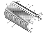
- FIG. 2 is a perspective view of a first indoor heat exchanger and a second indoor heat exchanger.
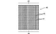
- FIG. 3 is a front view of the first indoor heat exchanger.
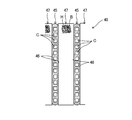
- FIG. 4 is an axial-perpendicular cross-sectional view of the flat tube in the main part of the first indoor heat exchanger, schematically showing the internal structure of the porous fin.
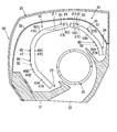
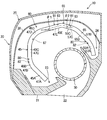
- FIG. 5 is a schematic configuration view showing an internal structure of the indoor unit, and is a diagram for describing a detailed configuration of the first indoor heat exchanger and the second indoor heat exchanger. 6 is a corresponding view of FIG. 4 according to the first modification.
- An air conditioner (1) regulates the temperature in a room.
- the air conditioner (1) switches between cooling operation and heating operation.
- the air conditioner (1) includes an outdoor unit (not shown) and an indoor unit (10).
- the outdoor unit and the indoor unit (10) are connected by a connecting pipe to form a refrigerant circuit.
- a vapor compression refrigeration cycle is performed by circulating the filled refrigerant.
- the indoor unit (10) of the air conditioning apparatus (1) of the present embodiment is a wall type provided on the wall surface (W).
- the indoor unit (10) of the present embodiment includes a casing (20), an air filter (28), a fan (30), a first indoor heat exchanger (40), and a second indoor heat exchanger (50). And have.
- the air filter (28), the fan (30), the first indoor heat exchanger (40), and the second indoor heat exchanger (50) are housed inside the casing (20).
- the casing (20) is formed in the shape of a horizontally long hollow box on the left and right.
- the casing (20) has a main body (21) and a cover (25) provided on the upper side of the main body (21).
- a blowout port (22) is formed to penetrate the rear of the main body (21).
- the blowout port (22) brings the interior of the casing (20) into communication with the indoor space.
- a first drain pan (23) and a second drain pan (24) are formed on the upper surface of the main body (21).
- the first drain pan (23) is disposed on the front side (left side in FIG. 1) of the blowout port (22).
- the second drain pan (24) is disposed on the rear side (right side in FIG. 1) of the blowout port (22).
- the first drain pan (23) and the second drain pan (24) are formed in a dish shape whose upper side is opened.
- the first drain pan (23) is located below the first indoor heat exchanger (40) and recovers the condensed water generated in the first indoor heat exchanger (40).
- the second drain pan (24) is located below the second indoor heat exchanger (50) and recovers the condensed water generated in the second indoor heat exchanger (50).
- the cover (25) is removably attached to the top of the main body (21).
- the cover (25) is formed with a plurality of suction ports (not shown).
- the suction port communicates the indoor space with the inside of the casing (20).
- the air filter (28) is provided above the first indoor heat exchanger (40) and the second indoor heat exchanger (50).
- the air filter (28) captures dust contained in the air upstream of the first indoor heat exchanger (40) and the second indoor heat exchanger (50).
- the air filter (28) is formed in a curved shape that bulges upward. That is, the air filter (28) is formed in a substantially U-shape or a C-shape which opens downward.
- the fan (30) conveys the air taken into the casing (20).
- the fan (30) of the present embodiment is configured in a cross flow type extending in the left-right direction of the casing (20).
- the fan (30) is disposed near the inflow end of the outlet (22) and between the first drain pan (23) and the second drain pan (24). Approximately half of the windward side of the fan (30) is exposed to the outside of the air outlet (22).
- the first indoor heat exchanger (40) and the second indoor heat exchanger (50) are arranged to surround the fan (30) as a whole.
- the first indoor heat exchanger (40) is disposed from the front to the upper side of the fan (30)
- the second indoor heat exchanger (50) is disposed from the rear to the upper side of the fan (30) It will be set up.
- the entire area facing the cover (25) constitutes the first inflow surface (41), and the entire area facing the fan (30) is the first outflow surface (42) ) Is configured.
- the entire area facing the cover (25) constitutes the second inflow surface (51), and the entire area facing the fan (30) is the second outflow surface (52) Configure).
- the first indoor heat exchanger (40) comprises one first upper header manifold (43), one first lower header manifold (44), and a plurality of first flats.
- a tube (45) and a plurality of first porous fins (47) are provided.
- the first upper header collecting pipe (43) is disposed above the first indoor heat exchanger (40).
- the first upper header collecting pipe (43) is formed in a horizontally extending cylindrical shape.
- the first lower header collecting pipe (44) is disposed below the first indoor heat exchanger (40).
- the first lower header collecting pipe (44) is formed in a horizontally extending cylindrical shape.
- the plurality of first flat tubes (45) constitute a heat transfer tube in which the refrigerant flows and heat is exchanged between the refrigerant and the air. More strictly, the plurality of first flat tubes (45) are flat multi-hole tubes in which a plurality of fine flow channels (C) are formed (see FIG. 4). Each first flat tube (45) of the present embodiment is formed in a substantially C-shape or a substantially U-shape. Each first flat tube (45) is curved so as to surround the outer periphery of the fan (30).
- the plurality of first flat tubes (45) are interposed between the first upper header collecting pipe (43) and the first lower header collecting pipe (44).
- first wide surfaces (46) are formed on both end sides in the thickness direction (left-right direction).
- the plurality of first flat tubes (45) are arranged in parallel so as to be adjacent to each other.
- the plurality of first flat tubes (45) are arranged in the horizontal direction such that the first wide surfaces (46) face sideways (left and right).
- each first flat tube (45) is connected to the first upper header collecting pipe (43).
- first flat tubes (45) and the first upper header collecting pipe (43) communicate with each other.
- the other longitudinal end (the lower end on the front side) of each first flat tube (45) is connected to the first lower header manifold (44).
- each 1st flat pipe (45) and the 1st lower header manifold (44) connect.
- the first porous fins (47) are respectively interposed between the adjacent first flat tubes (45).
- the first porous fin (47) is in contact with the first flat tube (45), and transfers heat to the first flat tube (45) or the refrigerant.
- Each first porous fin (47) extends from one end to the other end in the longitudinal direction of the first flat tube (45). That is, each first porous fin (47) is formed in a substantially C-shape or U-shape along the first flat tube (45). Each first porous fin (47) is curved so as to surround the outer periphery of the fan (30).
- the first porous fin (47) has a three-dimensionally continuous skeleton (B), and the plurality of three-dimensionally continuous pores (H) by the skeleton (B) Composed of a porous metal of a three-dimensional network structure to be formed.
- the skeleton (B) of the first porous fin (47) of the present embodiment is made of aluminum or an aluminum alloy.
- a ventilating path of air is formed by the communication of the large number of pores (H). That is, in the first indoor heat exchanger (40), the air introduced from the first inflow surface (41) flows through the pores (H) inside the first porous fins (47), Effluent outflow face (42). In the first porous fin (47), the heat transfer area is expanded by the three-dimensional continuity of the fine skeleton (B).
- the second indoor heat exchanger (50) includes one second upper header manifold (53), one second lower header manifold (54), and a plurality of second flat tubes (55). And a plurality of second porous fins (57).
- the second upper header collecting pipe (53) is disposed above the second indoor heat exchanger (50).
- the second upper header collecting pipe (53) is formed in a horizontally extending cylindrical shape.
- the second lower header manifold (54) is disposed below the second indoor heat exchanger (50).
- the second lower header collecting pipe (54) is formed in a horizontally extending cylindrical shape.
- the plurality of second flat tubes (55) constitute a heat transfer tube through which the refrigerant flows and heat is exchanged between the refrigerant and the air. More strictly, the plurality of second flat tubes (55) are flat multi-hole tubes in which a plurality of fine flow channels (C) are formed (similar to FIG. 4). Each second flat tube (55) of the present embodiment is formed in a concave shape that opens toward the fan (30) side.
- a plurality of second flat tubes (55) are interposed between the second upper header collecting pipe (53) and the second lower header collecting pipe (54).
- second wide surfaces (56) are formed on both end sides in the thickness direction (left-right direction).
- the plurality of second flat tubes (55) are arranged in parallel to be adjacent to each other.
- the plurality of second flat tubes (55) are arranged in the horizontal direction such that the respective second wide surfaces (56) face sideways (left and right).
- each second flat tube (55) One longitudinal end (upper end on the front side) of each second flat tube (55) is connected to the second upper header collecting pipe (53). Thereby, each second flat pipe (55) and the second upper header collecting pipe (53) communicate with each other.
- the other longitudinal end (rear lower end) of each second flat tube (55) is connected to a second lower header manifold (54). Thereby, each 2nd flat pipe (55) and 2nd lower header manifold (54) connect.
- the second porous fins (57) are respectively interposed between the adjacent second flat tubes (55).
- the second porous fin (57) is in contact with the second flat tube (55), and transfers heat to the second flat tube (55) or the refrigerant.
- Each second porous fin (57) extends from one end to the other end in the longitudinal direction of the second flat tube (55). That is, each second porous fin (57) is formed in a concave shape along the second flat tube (55).
- the second porous fins (57) have the same configuration as the first porous fins (47) described above.
- each of the first flat tubes (45) is a first lower flat tube portion (45A) in order from the first lower header manifold (44) to the first upper header manifold (43). And a first lower bending pipe (45B), a first intermediate flat pipe (45C), a first upper bending pipe (45D), and a first upper flat pipe (45E). That is, the first lower flat tube portion (45A), the first lower bent tube portion (45B), the first intermediate flat tube portion (45C), the first upper bent tube portion (45D), and the first upper flat tube
- the first flat tube (45) is configured by the portion (45E) continuing integrally.
- the first lower flat tube portion (45A), the first lower bent tube portion (45B), the first intermediate flat tube portion (45C), and the first upper bent tube portion (45D) are of the first drain pan (23).
- a drain pan side flat tube portion (80) disposed at the upper side is configured.
- the first upper flat tube portion (45E) constitutes a fan-side flat tube portion (81) disposed above the fan (30).
- the first lower flat tube portion (45A) is disposed in the vicinity of the first drain pan (23).
- the first lower flat tube portion (45A) may be in contact with the bottom surface of the first drain pan (23).
- the first lower flat tube portion (45A) extends from the vicinity of the first drain pan (23) to the upper front side.
- the first lower bent pipe portion (45B) is curved so as to connect the first lower flat pipe portion (45A) and the first intermediate flat pipe portion (45C).
- the first intermediate flat tube portion (45C) is disposed between the front portion of the cover (25) and the fan (30).
- the first intermediate flat tube portion (45C) extends in a substantially vertical direction.
- the first upper bent pipe portion (45D) is curved so as to connect the first intermediate flat pipe portion (45C) and the first upper flat pipe portion (45E).
- the first upper flat tube portion (45E) constitutes an inclined flat tube portion, and is disposed between the top of the cover (25) and the fan (30).
- the first upper flat tube portion (45E) extends slightly upward from the horizontal from the first upper bent tube portion (45D). Specifically, the first upper flat tube portion (45E) is inclined upward so that the tube axis forms ⁇ 1 larger than 0 ° and smaller than 45 ° with respect to the horizontal surface. That is, the first upper flat tube portion (45E) is disposed in a posture closer to the horizontal surface than the vertical surface.
- Each first porous fin (47) is disposed between each two adjacent first flat tubes (45).
- Each first porous fin (47) has a shape corresponding to the first flat tube (45).
- the first porous fins (47) are arranged in the order from the first lower header manifold (44) to the first upper header manifold (43) in the first lower fin portion (47A),
- a lower bending fin (47B), a first intermediate fin (47C), a first upper bending fin (47D), and a first upper fin (47E) are provided.
- the first porous fin (47) is configured by continuously connecting the two.
- the first lower fin portion (47A), the first lower bending fin portion (47B), the first intermediate fin portion (47C), and the first upper fin portion (47E) are located above the first drain pan (23)
- a drain pan side fin portion (82) to be disposed is configured.
- the first upper flat tube portion (45E) constitutes a fan-side fin portion (83) disposed above the fan (30).
- the first lower fin portion (47A) is interposed between two adjacent first lower flat tube portions (45A) so as to correspond to the first lower flat tube portion (45A).
- the first lower fin portion (47A) may be in contact with the bottom surface of the first drain pan (23).
- the first lower bending fin portion (47B) is curved so as to connect the first lower fin portion (47A) and the first intermediate fin portion (47C).
- the first intermediate fin portion (47C) is interposed between two adjacent first intermediate flat tube portions (45C) so as to correspond to the first intermediate flat tube portion (45C).
- the first upper bending fin portion (47D) is curved so as to connect the first intermediate fin portion (47C) and the first upper fin portion (47E).
- the first upper fin portion (47E) constitutes an inclined fin portion.
- the first upper fin portion (47E) is interposed between two adjacent first upper flat portions (45E) so as to correspond to the first upper flat portion (45E).
- the first upper fin portion (47E) is inclined upward such that a center line extending in the longitudinal direction thereof forms ⁇ 1 larger than 0 ° and smaller than 45 ° with respect to the horizontal plane.
- each second flat tube (55) is a second lower flat tube portion (55A) in order from the second lower header manifold (54) to the second upper header manifold (53).
- the second lower flat tube portion (55A) and the second intermediate flat tube portion (55B) constitute a drain pan side flat tube portion disposed above the second drain pan (24).
- the second upper flat tube portion (55C) constitutes a fan-side flat tube portion disposed above the fan (30).
- the second lower flat tube portion (55A) is disposed in the vicinity of the second drain pan (24).
- the second lower flat tube portion (55A) may be in contact with the bottom surface of the second drain pan (24).
- the second lower flat tube portion (55A) extends from the vicinity of the second drain pan (24) to the upper front side.
- the second intermediate flat tube portion (55B) connects the second lower flat tube portion (55A) and the second upper flat tube portion (55C).
- the second intermediate flat tube portion (55B) extends further to the upper front side from the second lower flat tube portion (55A).
- the second upper flat tube portion (55C) constitutes an inclined flat tube portion, and is disposed between the top of the cover (25) and the fan (30).
- the second upper flat tube portion (55C) extends slightly upward from the horizontal from the second intermediate flat tube portion (55B). Specifically, the second upper flat tube portion (55C) is inclined upward so that the tube axis forms ⁇ 2 larger than 0 ° and smaller than 45 ° with respect to the horizontal surface. That is, the second upper flat tube portion (55C) is disposed in a posture closer to the horizontal surface than the vertical surface.
- Each second porous fin (57) is disposed between each two adjacent second flat tubes (55).
- Each second porous fin (57) has a shape corresponding to the second flat tube (55).
- the second porous fin (57) is a second lower fin portion (57A), the second lower fin portion (57A) in order from the second lower header collecting pipe (54) to the second upper header collecting pipe (53).
- a middle fin portion (57B) and a second upper fin portion (57C) are provided. That is, the second lower fins (57A), the second intermediate fins (57B), and the second upper fins (57C) are integrally continuous to form a second porous fin (57).
- the second lower fin portion (57A) and the second intermediate fin portion (57B) constitute a drain pan side fin portion (82) disposed above the second drain pan (24).
- the second upper fin portion (57C) constitutes a fan-side fin portion (83) disposed above the fan (30).
- the second lower fin (57A) is interposed between two adjacent second lower flat tubes (55A) so as to correspond to the second lower flat tubes (55A).
- the second lower fin portion (57A) may be in contact with the bottom surface of the second drain pan (24).
- the second intermediate fin portion (57B) connects the second lower fin portion (57A) and the second upper fin portion (57C).
- the second intermediate fin portion (57B) is interposed between two adjacent second intermediate flat tube portions (55B) so as to correspond to the second intermediate flat tube portion (55B).
- the second upper fin portion (57C) constitutes an inclined fin portion.
- the second upper fin portion (57C) is interposed between two adjacent second upper flat tubes (55C) so as to correspond to the second upper flat tubes (55C).
- the second upper fin portion (57C) is inclined upward such that the center line extending in the longitudinal direction thereof forms ⁇ 2 larger than 0 ° and smaller than 45 ° with respect to the horizontal plane.
- the refrigerant condensed by the outdoor heat exchanger is reduced in pressure by the expansion valve and then sent to each indoor heat exchanger (60).
- the refrigerant is branched into, for example, the first lower header collecting pipe (44) and the second lower header collecting pipe (54).
- the refrigerant in the first lower header collecting pipe (44) is branched to each first flat pipe (45) and then joined in the first upper header collecting pipe (43). At this time, the refrigerant of each first flat tube (45) takes away the heat of the surrounding air and evaporates.
- the refrigerant in the second lower header collecting pipe (54) is branched to each second flat pipe (55), and then joined in the second upper header collecting pipe (53). At this time, the refrigerant of each second flat tube (55) takes away the heat of the surrounding air and evaporates.
- the refrigerant evaporated in each indoor heat exchanger (60) is drawn into the compressor and compressed.
- each indoor heat exchanger (60) flows around the fan (30) and is supplied from the outlet (22) to the indoor space.
- first porous fins (47) are interposed between the respective first flat tubes (45). For this reason, the air which flowed in between each 1st flat tube (45) flows through the pore (H) inside each 1st porous fin (47).
- each of the porous fins (47, 57) is made of a porous metal having a three-dimensional network structure, so that such scattering of condensed water can be prevented.
- each of the porous fins (47, 57) when the air flows through the pores (H), when the air in contact with each of the porous fins (47, 57) is cooled to the dew point temperature or lower, Condensed water is generated on the surface of each porous fin (47, 57). When the condensed water travels along the skeleton (B) and reaches the end of each porous fin (47, 57), it is retained inside the pores (H) by surface tension.
- the porous fins (47, 57) having a three-dimensional network structure an interface (wetted edge) with condensed water is formed at the opening edge of each pore (H), and the total length of these wetted edges is condensed It will contribute to the retention of water.
- the total length of the wetted edge is extremely large, so sufficient holding power for holding the condensed water inside the fins (47, 57, 67) You can get it. Therefore, since the condensed water can be reliably held inside the porous fins (47, 57), it is possible to suppress the condensed water from scattering into the air.
- the condensed water generated inside the first upper fin portion (47E) of the first indoor heat exchanger (40) does not fall to the fan (30) side, and the first upper flat tube portion (45E) Flow down diagonally downward and forward along the). That is, a flow passage for guiding the condensed water to the lower part of the first indoor heat exchanger (40) is formed between the adjacent first upper flat tube portions (45E).
- the condensed water reaching the lower end of the first upper flat tube portion (45E) is the first upper bent tube portion (45D), the first intermediate flat tube portion (45C), and the first lower bent tube portion (45B) in this order. It flows further downward inside the first porous fin (47) so as to pass through. Condensed water that has reached the first lower flat tube portion (45A) from the first lower bending tube portion (45B) is finally recovered to the inside of the first drain pan (23).
- the condensed water generated inside the second upper fin portion (57C) of the second indoor heat exchanger (50) does not fall to the fan (30) side, and the second upper flat tube portion (55C) It flows obliquely downward and backward along the). That is, a flow path for guiding the condensed water to the lower part of the second indoor heat exchanger (50) is formed between the adjacent second upper flat tube portions (55C).
- the condensed water that has reached the lower end of the second upper flat tube portion (55C) flows through the second intermediate flat tube portion (55B) and the second lower flat tube portion (55A) in order, and finally the second drain pan (24 It is recovered to the inside of).
- condensed water can be reliably hold
- scattering of condensed water into the air can be suppressed, and the reliability of the air conditioner (1) can be secured.
- the first porous fins (47) are interposed between the adjacent first flat tubes (45), and the second porous fins (57) are interposed between the adjacent second flat tubes (55). Is located. Therefore, the side surfaces on both sides of the porous fins (47, 57) can be closed by the flat tubes (45, 55). Therefore, it is possible to prevent the condensed water inside the porous fins (47, 57) from scattering into the air from the side surfaces on both sides of the porous fins (47, 57).
- the flat tubes (45, 55) are arranged such that their respective wide faces (46, 56) face to the left and right. That is, the wide surfaces (46, 56) of the flat tubes (45, 55) are not arranged to face up and down. Assuming that each wide surface (46, 56) of each flat tube (45, 55) faces up and down, condensed water is placed on the upper side of each wide surface (46, 56) of each flat tube (45, 55) May remain, and the ventilation resistance of each indoor heat exchanger (40, 50) may increase.
- the wide surfaces (46, 56) on both end sides in the thickness direction of the flat tubes (45, 55) are directed to the left and right, so each flat tube (45, 55) Condensed water hardly accumulates on the upper side of the Then, the condensed water flows downward along the wide surfaces (46, 56) of the flat tubes (45, 55). Therefore, it is possible to reliably prevent an increase in ventilation resistance caused by the condensation water accumulating on the upper side of each flat tube (45, 55).
- the tube axes of the first upper flat tube portion (45E) and the second upper flat tube portion (55C) are larger than 0 ° and smaller than 45 ° with respect to the horizontal plane. That is, the first upper flat tube portion (45E) and the second upper flat tube portion (55C) are in a posture close to horizontal.
- the first upper flat tube portion (45E) and the second upper flat tube portion (55C) can be compactly disposed in the space between the fan (30) and the cover (25).
- the condensed water generated inside the first upper fin portion (47E) is sent to the first drain pan (23) side along the first flat pipe (45) without dropping to the fan (30) side.
- the condensed water generated inside the second upper fin portion (57C) is not dropped to the fan (30) side, but is sent to the second drain pan (24) side along the second flat pipe (55). Therefore, while suppressing that the condensed water of the 1st upper side fin part (47E) splashes, increase of the draft resistance in this part can also be avoided.
- the condensed water of a 2nd upper side fin part (57C) splashes increase of the draft resistance in this part can also be avoided.
- the first flat tube (45) and the first porous fin (47) are formed in a substantially C shape, and are arranged to surround the outer periphery of the fan (30). With such an arrangement, the clearance between the fan (30) and the first indoor heat exchanger (40) can be sufficiently secured along the circumferential direction of the fan (30), and noise and pressure loss can be reduced. .
- the first flat tube (45) and the first porous fin (47) are curved between the air filter (28) and the first indoor heat exchanger (40) to curve along the air filter (28). Dead space can be minimized.
- the second flat tube (55) and the second porous fin (57) are curved along the air filter (28), the space between the cover (25) and the second indoor heat exchanger (50) The dead space formed in can be minimized. As a result, the space of the indoor unit (10) can be fully utilized.
- the first indoor heat exchanger (40) and the second indoor heat exchanger (50) of the above embodiment are integrated to constitute one indoor heat exchanger (60).
- the indoor heat exchanger (60) the first flat pipe (45) and the second flat pipe (55) according to the embodiment are connected to constitute one flat pipe (65).
- a plurality of porous fins (67) are interposed between adjacent flat tubes (65).
- ⁇ 1 of the first upper flat tube portion (45E) and ⁇ 2 of the second upper flat tube portion (55C) are respectively in the range of more than 0 ° and less than 45 °.
- Condensed water generated in the first upper fin portion (47E) flows downward along the first flat pipe (45) and is finally sent to the first drain pan (23) side.
- Condensed water generated in the second upper fin portion (57C) flows downward along the second flat pipe (55) and is finally sent to the second drain pan (24) side.
- a plurality of flat tubes (45, 55, 65) are arranged laterally.
- a plurality of flat tubes (45, 55, 65) may be arranged vertically, and porous fins (47, 57, 67) may be interposed between adjacent flat tubes (45, 55, 65). . Also in this case, scattering of the condensed water can be avoided by the porous fins (47, 57, 67).
- heat transfer pipes of other shapes such as straight pipes may be used instead of the flat pipes (45, 55, 65). Also in this case, scattering of the condensed water can be avoided by interposing the porous fins (47, 57, 67) between the adjacent heat transfer pipes.
- the indoor unit may not be wall-mounted, and may be, for example, ceiling-mounted (ceiling-to-ceiling-mounted) or floor-mounted.
- the fan (30) may not be a cross flow type, and may be a turbo fan or a propeller fan.
- the present invention is useful for an indoor unit of an air conditioner.
- first indoor heat exchanger 45 first flat pipe (heat transfer pipe) 45E 1st upper flat tube (inclined flat tube) 46 1st wide surface 47E 1st upper fin part (inclined fin part) 50 second indoor heat exchanger 55 second flat tube (heat transfer tube) 55C inclined flat tube portion 56 second wide surface 57C inclined fin portion 60 indoor heat exchanger 65 flat tube (heat transfer tube) 66 wide surface 80 drain pan side flat tube portion 81 fan side flat tube portion 82 drain pan side fin portion 83 fan side fin portion
Landscapes
- Engineering & Computer Science (AREA)
- Physics & Mathematics (AREA)
- Thermal Sciences (AREA)
- Mechanical Engineering (AREA)
- General Engineering & Computer Science (AREA)
- Chemical & Material Sciences (AREA)
- Dispersion Chemistry (AREA)
- Combustion & Propulsion (AREA)
- Devices For Blowing Cold Air, Devices For Blowing Warm Air, And Means For Preventing Water Condensation In Air Conditioning Units (AREA)
- Air-Conditioning Room Units, And Self-Contained Units In General (AREA)
- Air Filters, Heat-Exchange Apparatuses, And Housings Of Air-Conditioning Units (AREA)
- Heat-Exchange Devices With Radiators And Conduit Assemblies (AREA)
Abstract
本発明の目的は、伝熱管やフィンの表面で発生した凝縮水が空気中へ飛散してしまうことを抑制できる空気調和装置の室内ユニットを提供することである。室内熱交換器(40,50,60)のフィン(47,57,67)は、三次元的に連続する骨格(B)を有するとともに、該骨格(B)により三次元的に連続する複数の気孔(H)を形成する三次元網目状構造の多孔質金属で構成される。
Description
本発明は、空気調和装置の室内ユニットに関する。
従来より、空気調和装置が広く知られている。
例えば特許文献1の空気調和装置は、壁掛け式の室内ユニットを備えている。室内ユニットのケーシングには、室内熱交換器及びファンが収容される。吸込口からケーシング内に取り込まれた空気は、室内熱交換器を通過する。例えば冷房運転では、室内熱交換器を流れる冷媒が、伝熱管及びフィンを介して空気と熱交換する。この結果、室内熱交換器では、冷媒が蒸発し、空気が冷却される。冷却された空気は、吹出口より室内空間へ供給される。
このような冷房運転において、室内熱交換器により空気が露点温度以下まで冷却されると、伝熱管やフィンの表面で凝縮水(結露水)が発生する。このため、室内熱交換器の下側には、空気中で発生した凝縮水を回収するためのドレンパンが設けられる。
特許文献1に開示のような室内ユニットでは、ケーシング内のレイアウトの制約上、室内熱交換器の一部をドレンパンの外側に配置したり、この室内熱交換器を水平寄りに傾けて配置したりすることが想定される。ところが、このような配置では、伝熱管やフィンの表面で発生した凝縮水が、ドレンパンに回収されずに空気中へ飛散してしまう可能性がある。
本発明は、このような点に着目してなされたものであり、伝熱管やフィンの表面で発生した凝縮水が空気中へ飛散してしまうことを抑制できる空気調和装置の室内ユニットを提供することである。
第1の発明は、ケーシング(20)と、前記ケーシング(20)に収容され、空気を搬送するファン(30)と、前記ケーシング(20)に収容され、前記ファン(30)で搬送された空気を冷媒によって冷却可能な少なくとも1つの室内熱交換器(40,50,60)とを備え、前記室内熱交換器(40,50,60)は、伝熱管(45,55,65)と、前記伝熱管(45,55,65)と伝熱可能なフィン(47,57,67)とを有し、前記フィン(47,57,67)は、三次元的に連続する骨格(B)を有するとともに、該骨格(B)により三次元的に連通する複数の気孔(H)を形成する三次元網目状構造の多孔質金属で構成されることを特徴とする空気調和装置の室内ユニットである。
第1の発明では、ファン(30)によってケーシング(20)内に取り込まれた空気が、室内熱交換器(40,50,60)を通過する。ここで、本発明のフィン(47,57,67)は、三次元的に連続する骨格(B)を有するとともに、該骨格(B)により三次元的に連続する複数の気孔(H)を形成する三次元網目状構造の多孔質金属で構成される。このため、空気は、連続する複数の気孔(H)を流れ、フィン(47,57,67)の骨格(B)と熱交換し、冷却される。フィン(47,57,67)は、三次元網目状構造であるため、空気とフィン(47,57,67)との間の伝熱面積は比較的大きい。このため、空気の冷却効率が向上する。
一方、空気が気孔(H)を流れる際、フィン(47,57,67)の表面に接触する空気が露点温度以下にまで冷却されると、フィン(47,57,67)表面において凝縮水が発生する。この凝縮水が、骨格(B)を伝ってフィン(47,57,67)の端部に至ると、表面張力により、気孔(H)の内部に保持される。ここで、三次元網目状構造のフィン(47,57,67)では、各気孔(H)の開口縁部に凝縮水との界面(濡れ縁)がそれぞれ形成され、これらの濡れ縁の総長さが凝縮水の保持力に寄与することになる。三次元網目状構造のフィン(47,57,67)では、この濡れ縁の総長さが極めて大きくなるため、凝縮水をフィン(47,57,67)の内部に保持するための十分な保持力を得ることができる。従って、本発明では、凝縮水をフィン(47,57,67)の内部に確実に保持できるため、凝縮水が空気中へ飛散してしまうことを抑制できる。
第2の発明は、第1の発明において、前記伝熱管は、隣り合うように配列される複数の扁平管(45,55,65)で構成され、前記フィン(47,57,67)が、隣り合う各2つの前記扁平管(45,55,65)の間にそれぞれ介設されることを特徴とする空気調和装置の室内ユニットである。
第2の発明では、隣り合う各2つの扁平管(45,55,65)の間に流入した空気が、各フィン(47,57,67)の気孔(H)をそれぞれ流通する。この結果、気孔(H)を流れる空気の熱が、フィン(47,57,67)の骨格(B)及び扁平管(45,55,65)を介して冷媒に伝導する。
本発明では、各フィン(47,57,67)が2つの扁平管(45,55,65)に挟まれる。つまり、フィン(47,57,67)の2つの面が扁平管(45,55,65)によって閉塞される。このため、フィン(47,57,67)の内部で発生した凝縮水が、これらの2つの面から空気中へ飛散してしまうことがない。この結果、凝縮水が空気中へ飛散してしまうことをより確実に抑制できる。
第3の発明は、第2の発明において、各扁平管(45,55,65)は、該扁平管(45,55,65)の厚さ方向の両端側の各幅広面(46,56,66)がそれぞれ側方を向くように配列されることを特徴とする空気調和装置の室内ユニットである。
第3の発明では、扁平管(45,55,65)の厚さ方向の両端側の各幅広面(46,56,66)が、側方を向くように配置される。つまり、扁平管(45,55,65)の各幅広面(46,56,66)は上下を向くように配置されない。仮に、扁平管(45,55,65)の各幅広面(46,56,66)が上下を向くように配置すると、扁平管(45,55,65)の幅広面(46,56,66)の上側に凝縮水が留まってしまい、室内熱交換器(40,50,60)の通風抵抗が増大してしまう可能性がある。これに対し、本発明では、扁平管(45,55,65)の厚さ方向の両端側の各幅広面(46,56,66)が、側方を向いているため、扁平管(45,55,65)の上側に凝縮水が溜まることがほとんどない。そして、この凝縮水は、扁平管(45,55,65)の幅広面(46,56,66)に沿うようにして下方へ流れ落ちていく。従って、扁平管(45,55,65)の上側に凝縮水が溜まることに起因する通風抵抗の増大を確実に防止できる。
第4の発明は、第3の発明において、前記扁平管(45,55,65)は、その管軸が水平面に対して0°より大きく45°よりも小さい角度θ1をなすように上側に傾斜した傾斜扁平管部(45E,55C)を含み、前記フィン(47,57,67)は、前記傾斜扁平管部(45E,55C)に対応する傾斜フィン部(47E,57C)を含んでいることを特徴とする空気調和装置の室内ユニットである。
第4の発明では、扁平管(45,55,65)の少なくとも一部が扁平管傾斜部(45E,55C)を有し、フィン(47,57,67)の少なくとも一部が扁平管傾斜部(45E,55C)に対応するフィン傾斜部(47E,57C)を有する。扁平管傾斜部(45E,55C)の管軸は、水平面に対して0°より大きく45°よりも小さい。即ち、扁平管傾斜部(45E,55C)及びフィン傾斜部(47E,57C)は、水平に近い姿勢となる。従って、傾斜角度が45°以上の場合の熱交換器に対して同一高さでの熱交換器の通過面積を大きく確保できる、あるいは室内熱交換器(40,50,60)のレイアウトの自由度が向上する。この結果、室内ユニットのスペースを最大限に有効活用した熱交換器(40,50,60)の設置を図ることができる。
一方、従来例の伝熱管及びフィンの少なくとも一部を水平に近い姿勢とすると、フィンを通過する際に発生した凝縮水が下方へ飛散し易くなる。これに対し、本発明の三次元網目状構造のフィン(47,57,67)は、上述の如く、その内部に凝縮水を保持できるため、フィン傾斜部(47E,57C)で発生した凝縮水が下方へ飛散することを抑制できる。従って、室内ユニットのコンパクト化を図りつつ、凝縮水の飛散を防止できる。
第5の発明は、第3又は4の発明において、前記室内熱交換器(40,50,60)で発生した凝縮水を回収するドレンパン(23,24)を備え、前記扁平管(45,55,65)は、前記ファン(30)の上方に配置されるファン側扁平管部(81)と、前記ドレンパン(23,24)の上方に配置されるとともに、ファン側扁平管部(81)の下端に連続するドレンパン側扁平管部(80)とを有し、前記フィン(47,57,67)は、前記ファン側扁平管部(81)に対応するファン側フィン部(83)と、前記ドレンパン側扁平管部(80)に対応するドレンパン側フィン部(82)とを有することを特徴とする空気調和装置の室内ユニットである。
第5の発明では、ファン(30)の上方にファン側扁平管部(81)及びファン側フィン部(83)が配置される。ファン側フィン部(83)は、三次元網目状構造であり、その内部に凝縮水を保持できる。従って、ファン側フィン部(83)で発生した凝縮水が、ファン(30)側に飛散され、室内空間へ運ばれてしまうことを回避できる。
ファン側フィン部(83)で発生した凝縮水は、ファン側扁平管部(81)の下端まで流れ落ちた後、ドレンパン側扁平管部(80)及びドレンパン側フィン部(82)へ運ばれる。ドレンパン側扁平管部(80)及びドレンパン側フィン部(82)の下側にはドレンパン(23,24)が配置される。このため、ドレンパン側フィン部(82)側へ運ばれた凝縮水をドレンパン(23,24)の内部に回収できる。
第6の発明は、第3乃至5の発明のいずれか1つにおいて、前記ファン(30)は、クロスフロー型に構成され、前記扁平管(45,55,65)及び前記フィン(47,57,67)は、前記ファン(30)の外周を囲むように略Cの字状に湾曲していることを特徴とする空気調和装置の室内ユニットである。
第6の発明では、扁平管(45,55,65)及びフィン(47,57,67)が略Cの字状に形成され、ファン(30)の外周を囲むように配置される。このような配置にすると、ファン(30)と室内熱交換器(40,50,60)との間のクリアランスを、ファン(30)の周方向に亘って十分に確保でき、騒音や圧力損失を低減できる。また、ファン(30)と室内熱交換器(40,50,60)との間に形成されるデッドスペースを最小化でき、室内ユニットのコンパクト化を図ることができる。
一方、従来例の扁平管及びフィンを略Cの字状に形成すると、特に水平な姿勢に近い部分において、凝縮水が下方に飛散し易くなる。これに対し、本発明の三次元網目状構造のフィン(47,57,67)は、上述の如く、その内部に凝縮水を保持できるため、水平な姿勢に近い部分で発生した凝縮水が下方へ飛散することを抑制できる。従って、室内ユニットのコンパクト化を図りつつ、凝縮水の飛散を防止できる。
本発明によれば、三次元網目状構造の多孔質金属からなるフィン(47,57,67)の内部に凝縮水を確実に保持できる。このため、凝縮水が空気中へ飛散してしまうことを回避できる。このようにして、凝縮水の飛散を回避できると、室内熱交換器(40,50,60)のレイアウトの自由度が向上する。このため、室内ユニットのコンパクト化を図ることができる。
以下、本発明の実施形態について図面を参照しながら説明する。なお、以下の実施形態は、本質的に好ましい例示であって、本発明、その適用物、あるいはその用途の範囲を制限することを意図するものではない。
〈全体構成〉
本発明に係る空気調和装置(1)は、室内の温度を調節する。空気調和装置(1)は、冷房運転と暖房運転とを切り換えて行う。空気調和装置(1)は、室外ユニット(図示省略)と、室内ユニット(10)とを備える。空気調和装置(1)では、室外ユニットと室内ユニット(10)とが連絡配管で接続され、冷媒回路が構成される。冷媒回路では、充填された冷媒が循環することで、蒸気圧縮式の冷凍サイクルが行われる。
本発明に係る空気調和装置(1)は、室内の温度を調節する。空気調和装置(1)は、冷房運転と暖房運転とを切り換えて行う。空気調和装置(1)は、室外ユニット(図示省略)と、室内ユニット(10)とを備える。空気調和装置(1)では、室外ユニットと室内ユニット(10)とが連絡配管で接続され、冷媒回路が構成される。冷媒回路では、充填された冷媒が循環することで、蒸気圧縮式の冷凍サイクルが行われる。
図1に示すように、本実施形態の空気調和装置(1)の室内ユニット(10)は、壁面(W)に設けられる壁掛け式である。本実施形態の室内ユニット(10)は、ケーシング(20)と、エアフィルタ(28)と、ファン(30)と、第1室内熱交換器(40)と、第2室内熱交換器(50)とを備えている。エアフィルタ(28)、ファン(30)、第1室内熱交換器(40)、及び第2室内熱交換器(50)は、ケーシング(20)の内部に収容される。
〈ケーシング〉
ケーシング(20)は、左右に横長の中空箱状に形成される。ケーシング(20)は、本体部(21)と、該本体部(21)の上側に設けられるカバー(25)とを有する。
ケーシング(20)は、左右に横長の中空箱状に形成される。ケーシング(20)は、本体部(21)と、該本体部(21)の上側に設けられるカバー(25)とを有する。
本体部(21)の後方寄りには、吹出口(22)が貫通して形成される。吹出口(22)は、ケーシング(20)の内部と室内空間とを連通させる。
本体部(21)の上面には、第1ドレンパン(23)と第2ドレンパン(24)とが形成される。第1ドレンパン(23)は、吹出口(22)の前側(図1の左側)に配置される。第2ドレンパン(24)は、吹出口(22)の後側(図1の右側)に配置される。第1ドレンパン(23)及び第2ドレンパン(24)は、上側が開放される皿状に形成される。第1ドレンパン(23)は、第1室内熱交換器(40)の下側に位置し、第1室内熱交換器(40)で発生した凝縮水を回収する。第2ドレンパン(24)は、第2室内熱交換器(50)の下側に位置し、第2室内熱交換器(50)で発生した凝縮水を回収する。
カバー(25)は、本体部(21)の上部に着脱可能に取り付けられる。カバー(25)には、複数の吸込口(図示省略)が形成される。吸込口は、室内空間とケーシング(20)の内部とを連通させる。
〈エアフィルタ〉
エアフィルタ(28)は、第1室内熱交換器(40)及び第2室内熱交換器(50)の上側に設けられる。エアフィルタ(28)は、第1室内熱交換器(40)及び第2室内熱交換器(50)の上流側の空気中に含まれる塵埃を捕捉する。エアフィルタ(28)は、上方に向かって膨出する曲面状に形成される。即ち、エアフィルタ(28)は、下側に開放する略Uの字状ないし略Cの字状に形成される。
エアフィルタ(28)は、第1室内熱交換器(40)及び第2室内熱交換器(50)の上側に設けられる。エアフィルタ(28)は、第1室内熱交換器(40)及び第2室内熱交換器(50)の上流側の空気中に含まれる塵埃を捕捉する。エアフィルタ(28)は、上方に向かって膨出する曲面状に形成される。即ち、エアフィルタ(28)は、下側に開放する略Uの字状ないし略Cの字状に形成される。
〈ファン〉
ファン(30)は、ケーシング(20)内に取り込んだ空気を搬送する。本実施形態のファン(30)は、ケーシング(20)の左右方向に延びるクロスフロー型で構成される。ファン(30)は、吹出口(22)の流入端付近であって、第1ドレンパン(23)と第2ドレンパン(24)との間に配置される。ファン(30)の風上側の略半分は、吹出口(22)の外部に露出している。
ファン(30)は、ケーシング(20)内に取り込んだ空気を搬送する。本実施形態のファン(30)は、ケーシング(20)の左右方向に延びるクロスフロー型で構成される。ファン(30)は、吹出口(22)の流入端付近であって、第1ドレンパン(23)と第2ドレンパン(24)との間に配置される。ファン(30)の風上側の略半分は、吹出口(22)の外部に露出している。
〈室内熱交換器の概要〉
図1に示すように、第1室内熱交換器(40)及び第2室内熱交換器(50)は、全体として、ファン(30)を囲むように配置される。第1室内熱交換器(40)は、ファン(30)の前側から上側に亘って配設され、第2室内熱交換器(50)は、ファン(30)の後側から上側に亘って配設される。
図1に示すように、第1室内熱交換器(40)及び第2室内熱交換器(50)は、全体として、ファン(30)を囲むように配置される。第1室内熱交換器(40)は、ファン(30)の前側から上側に亘って配設され、第2室内熱交換器(50)は、ファン(30)の後側から上側に亘って配設される。
第1室内熱交換器(40)では、カバー(25)側を向く全体の領域が第1流入面(41)を構成し、ファン(30)側を向く全体の領域が第1流出面(42)を構成している。第2室内熱交換器(50)では、カバー(25)側を向く全体の領域が第2流入面(51)を構成し、ファン(30)側を向く全体の領域が第2流出面(52)を構成する。
〈第1室内熱交換器の全体構成〉
図2及び図3に示すように、第1室内熱交換器(40)は、1つの第1上部ヘッダ集合管(43)、1つの第1下部ヘッダ集合管(44)、複数の第1扁平管(45)、及び複数の第1多孔質フィン(47)を備えている。
図2及び図3に示すように、第1室内熱交換器(40)は、1つの第1上部ヘッダ集合管(43)、1つの第1下部ヘッダ集合管(44)、複数の第1扁平管(45)、及び複数の第1多孔質フィン(47)を備えている。
第1上部ヘッダ集合管(43)は、第1室内熱交換器(40)の上部に配置される。第1上部ヘッダ集合管(43)は、水平方向に延びる筒状に形成される。第1下部ヘッダ集合管(44)は、第1室内熱交換器(40)の下部に配置される。第1下部ヘッダ集合管(44)は、水平方向に延びる筒状に形成される。
複数の第1扁平管(45)は、冷媒が流れるとともに、該冷媒と空気とを熱交換させる伝熱管を構成している。より厳密には、複数の第1扁平管(45)は、複数の微細な流路(C)が形成される扁平多穴管である(図4を参照)。本実施形態の各第1扁平管(45)は、略Cの字状ないし略Uの字状に形成される。各第1扁平管(45)は、ファン(30)の外周を囲むように湾曲している。
複数の第1扁平管(45)は、第1上部ヘッダ集合管(43)と第1下部ヘッダ集合管(44)との間に介設される。各第1扁平管(45)には、それらの厚さ方向(左右方向)の両端側にそれぞれ第1幅広面(46)が形成される。複数の第1扁平管(45)は、互いに隣り合うように平行に配列される。複数の第1扁平管(45)は、各第1幅広面(46)が側方(左右)を向くように水平方向に配列される。
各第1扁平管(45)の長手方向の一端(後側の上端部)は、第1上部ヘッダ集合管(43)に接続する。これにより、各第1扁平管(45)と第1上部ヘッダ集合管(43)とが連通する。各第1扁平管(45)の長手方向の他端(前側の下端部)は、第1下部ヘッダ集合管(44)に接続する。これにより、各第1扁平管(45)と第1下部ヘッダ集合管(44)とが連通する。
図3及び図4に示すように、第1多孔質フィン(47)は、隣り合う第1扁平管(45)の間にそれぞれ介設される。第1多孔質フィン(47)は、第1扁平管(45)と接触しており、該第1扁平管(45)ないし冷媒と伝熱する。
各第1多孔質フィン(47)は、第1扁平管(45)の長手方向の一端から他端に亘るように延びている。つまり、各第1多孔質フィン(47)は、第1扁平管(45)に沿うような略Cの字状ないしUの字状に形成される。各第1多孔質フィン(47)は、ファン(30)の外周を囲むように湾曲している。
図4に示すように、第1多孔質フィン(47)は、三次元的に連続する骨格(B)を有するとともに、該骨格(B)により三次元的に連続する複数の気孔(H)を形成する三次元網目状構造の多孔質金属で構成される。本実施形態の第1多孔質フィン(47)の骨格(B)は、アルミニウム又はアルミニウム合金により構成される。
第1多孔質フィン(47)の内部では、多数の気孔(H)が連通することで空気の通風路が構成される。つまり、第1室内熱交換器(40)では、第1流入面(41)から導入された空気が、各第1多孔質フィン(47)の内部の気孔(H)を流れた後、第1流出面(42)を流出する。第1多孔質フィン(47)では、微細な骨格(B)が三次元的に連続することで、伝熱面積の拡大が図られている。
〈第2室内熱交換器の全体構成〉
図2に示すように、第2室内熱交換器(50)は、1つの第2上部ヘッダ集合管(53)、1つの第2下部ヘッダ集合管(54)、複数の第2扁平管(55)、及び複数の第2多孔質フィン(57)を備えている。
図2に示すように、第2室内熱交換器(50)は、1つの第2上部ヘッダ集合管(53)、1つの第2下部ヘッダ集合管(54)、複数の第2扁平管(55)、及び複数の第2多孔質フィン(57)を備えている。
第2上部ヘッダ集合管(53)は、第2室内熱交換器(50)の上部に配置される。第2上部ヘッダ集合管(53)は、水平方向に延びる筒状に形成される。第2下部ヘッダ集合管(54)は、第2室内熱交換器(50)の下部に配置される。第2下部ヘッダ集合管(54)は、水平方向に延びる筒状に形成される。
複数の第2扁平管(55)は、冷媒が流れるとともに、該冷媒と空気とを熱交換させる伝熱管を構成している。より厳密には、複数の第2扁平管(55)は、複数の微細な流路(C)が形成される扁平多穴管である(図4と同様)。本実施形態の各第2扁平管(55)は、ファン(30)側に開放する凹状に形成される。
複数の第2扁平管(55)は、第2上部ヘッダ集合管(53)と第2下部ヘッダ集合管(54)との間に介設される。各第2扁平管(55)には、それらの厚さ方向(左右方向)の両端側にそれぞれ第2幅広面(56)が形成される。複数の第2扁平管(55)は、互いに隣り合うように平行に配列される。複数の第2扁平管(55)は、各第2幅広面(56)が側方(左右)を向くように水平方向に配列される。
各第2扁平管(55)の長手方向の一端(前側の上端部)は、第2上部ヘッダ集合管(53)に接続する。これにより、各第2扁平管(55)と第2上部ヘッダ集合管(53)とが連通する。各第2扁平管(55)の長手方向の他端(後側の下端部)は、第2下部ヘッダ集合管(54)に接続される。これにより、各第2扁平管(55)と第2下部ヘッダ集合管(54)とが連通する。
第2多孔質フィン(57)は、隣り合う第2扁平管(55)の間にそれぞれ介設される。第2多孔質フィン(57)は、第2扁平管(55)と接触しており、該第2扁平管(55)ないし冷媒と伝熱する。
各第2多孔質フィン(57)は、第2扁平管(55)の長手方向の一端から他端に亘るように延びている。つまり、各第2多孔質フィン(57)は、第2扁平管(55)に沿うような凹状に形成される。
第2多孔質フィン(57)は、上述した第1多孔質フィン(47)と同様の構成である。
〈第1扁平管の詳細な構成〉
図5に示すように、各第1扁平管(45)は、第1下部ヘッダ集合管(44)から第1上部ヘッダ集合管(43)に向かって順に、第1下側扁平管部(45A)、第1下側曲げ管部(45B)、第1中間扁平管部(45C)、第1上側曲げ管部(45D)、及び第1上側扁平管部(45E)を備えている。即ち、第1下側扁平管部(45A)、第1下側曲げ管部(45B)、第1中間扁平管部(45C)、第1上側曲げ管部(45D)、及び第1上側扁平管部(45E)が一体に連続することで第1扁平管(45)が構成される。第1下側扁平管部(45A)、第1下側曲げ管部(45B)、第1中間扁平管部(45C)、第1上側曲げ管部(45D)は、第1ドレンパン(23)の上方に配置されるドレンパン側扁平管部(80)を構成する。第1上側扁平管部(45E)は、ファン(30)の上方に配置されるファン側扁平管部(81)を構成する。
図5に示すように、各第1扁平管(45)は、第1下部ヘッダ集合管(44)から第1上部ヘッダ集合管(43)に向かって順に、第1下側扁平管部(45A)、第1下側曲げ管部(45B)、第1中間扁平管部(45C)、第1上側曲げ管部(45D)、及び第1上側扁平管部(45E)を備えている。即ち、第1下側扁平管部(45A)、第1下側曲げ管部(45B)、第1中間扁平管部(45C)、第1上側曲げ管部(45D)、及び第1上側扁平管部(45E)が一体に連続することで第1扁平管(45)が構成される。第1下側扁平管部(45A)、第1下側曲げ管部(45B)、第1中間扁平管部(45C)、第1上側曲げ管部(45D)は、第1ドレンパン(23)の上方に配置されるドレンパン側扁平管部(80)を構成する。第1上側扁平管部(45E)は、ファン(30)の上方に配置されるファン側扁平管部(81)を構成する。
第1下側扁平管部(45A)は、第1ドレンパン(23)の近傍に配置される。なお、第1下側扁平管部(45A)は、第1ドレンパン(23)の底面と接触してもよい。第1下側扁平管部(45A)は、第1ドレンパン(23)付近から前方上側へと延びている。
第1下側曲げ管部(45B)は、第1下側扁平管部(45A)と第1中間扁平管部(45C)とを繋ぐように湾曲している。第1中間扁平管部(45C)は、カバー(25)の前側部分とファン(30)の間に配置される。第1中間扁平管部(45C)は、概ね垂直方向に延びている。第1上側曲げ管部(45D)は、第1中間扁平管部(45C)と第1上側扁平管部(45E)とを繋ぐように湾曲している。
第1上側扁平管部(45E)は、傾斜扁平管部を構成しており、カバー(25)の頂部とファン(30)の間に配置される。第1上側扁平管部(45E)は、第1上側曲げ管部(45D)から水平よりやや上向きに延びている。具体的には、第1上側扁平管部(45E)は、その管軸が水平面に対して0°より大きく45°より小さいθ1をなすように、上側に傾斜している。つまり、第1上側扁平管部(45E)は、垂直面よりも水平面に近い姿勢で配設される。
〈第1多孔質フィンの詳細な構成〉
各第1多孔質フィン(47)は、隣り合う各2つの第1扁平管(45)の間に配置される。各第1多孔質フィン(47)は、第1扁平管(45)に対応する形状をしている。具体的には、第1多孔質フィン(47)は、第1下部ヘッダ集合管(44)から第1上部ヘッダ集合管(43)に向かって順に、第1下側フィン部(47A)、第1下側曲げフィン部(47B)、第1中間フィン部(47C)、第1上側曲げフィン部(47D)、及び第1上側フィン部(47E)を備えている。即ち、第1下側フィン部(47A)、第1下側曲げフィン部(47B)、第1中間フィン部(47C)、第1上側曲げフィン部(47D)、及び第1上側フィン部(47E)が一体に連続することで第1多孔質フィン(47)が構成される。第1下側フィン部(47A)、第1下側曲げフィン部(47B)、第1中間フィン部(47C)、及び第1上側フィン部(47E)は、第1ドレンパン(23)の上方に配置されるドレンパン側フィン部(82)を構成する。第1上側扁平管部(45E)は、ファン(30)の上方に配置されるファン側フィン部(83)を構成する。
各第1多孔質フィン(47)は、隣り合う各2つの第1扁平管(45)の間に配置される。各第1多孔質フィン(47)は、第1扁平管(45)に対応する形状をしている。具体的には、第1多孔質フィン(47)は、第1下部ヘッダ集合管(44)から第1上部ヘッダ集合管(43)に向かって順に、第1下側フィン部(47A)、第1下側曲げフィン部(47B)、第1中間フィン部(47C)、第1上側曲げフィン部(47D)、及び第1上側フィン部(47E)を備えている。即ち、第1下側フィン部(47A)、第1下側曲げフィン部(47B)、第1中間フィン部(47C)、第1上側曲げフィン部(47D)、及び第1上側フィン部(47E)が一体に連続することで第1多孔質フィン(47)が構成される。第1下側フィン部(47A)、第1下側曲げフィン部(47B)、第1中間フィン部(47C)、及び第1上側フィン部(47E)は、第1ドレンパン(23)の上方に配置されるドレンパン側フィン部(82)を構成する。第1上側扁平管部(45E)は、ファン(30)の上方に配置されるファン側フィン部(83)を構成する。
第1下側フィン部(47A)は、第1下側扁平管部(45A)に対応するように、隣り合う2つの第1下側扁平管部(45A)の間に介設される。なお、第1下側フィン部(47A)は、第1ドレンパン(23)の底面と接触してもよい。
第1下側曲げフィン部(47B)は、第1下側フィン部(47A)と第1中間フィン部(47C)とを繋ぐように湾曲している。第1中間フィン部(47C)は、第1中間扁平管部(45C)に対応するように、隣り合う2つの第1中間扁平管部(45C)の間に介設される。第1上側曲げフィン部(47D)は、第1中間フィン部(47C)と第1上側フィン部(47E)とを繋ぐように湾曲している。
第1上側フィン部(47E)は、傾斜フィン部を構成している。第1上側フィン部(47E)は、第1上側扁平管部(45E)に対応するように、隣り合う2つの第1上側扁平管部(45E)の間に介設される。具体的には、第1上側フィン部(47E)は、その長手方向に延びる中心線が水平面に対して0°より大きく45°より小さいθ1をなすように、上側に傾斜している。
〈第2扁平管の詳細な構成〉
図5に示すように、各第2扁平管(55)は、第2下部ヘッダ集合管(54)から第2上部ヘッダ集合管(53)に向かって順に、第2下側扁平管部(55A)、第2中間扁平管部(55B)、及び第2上側扁平管部(55C)を備えている。即ち、第2下側扁平管部(55A)、第2中間扁平管部(55B)、及び第2上側扁平管部(55C)が一体に連続することで第2扁平管(55)が構成される。第2下側扁平管部(55A)及び第2中間扁平管部(55B)は、第2ドレンパン(24)の上方に配置されるドレンパン側扁平管部を構成する。第2上側扁平管部(55C)は、ファン(30)の上方に配置されるファン側扁平管部を構成する。
図5に示すように、各第2扁平管(55)は、第2下部ヘッダ集合管(54)から第2上部ヘッダ集合管(53)に向かって順に、第2下側扁平管部(55A)、第2中間扁平管部(55B)、及び第2上側扁平管部(55C)を備えている。即ち、第2下側扁平管部(55A)、第2中間扁平管部(55B)、及び第2上側扁平管部(55C)が一体に連続することで第2扁平管(55)が構成される。第2下側扁平管部(55A)及び第2中間扁平管部(55B)は、第2ドレンパン(24)の上方に配置されるドレンパン側扁平管部を構成する。第2上側扁平管部(55C)は、ファン(30)の上方に配置されるファン側扁平管部を構成する。
第2下側扁平管部(55A)は、第2ドレンパン(24)の近傍に配置される。なお、第2下側扁平管部(55A)は、第2ドレンパン(24)の底面と接触してもよい。第2下側扁平管部(55A)は、第2ドレンパン(24)付近から前方上側へと延びている。第2中間扁平管部(55B)は、第2下側扁平管部(55A)と第2上側扁平管部(55C)とを繋いでいる。第2中間扁平管部(55B)は、第2下側扁平管部(55A)から更に前方上側へと延びている。
第2上側扁平管部(55C)は、傾斜扁平管部を構成しており、カバー(25)の頂部とファン(30)の間に配置される。第2上側扁平管部(55C)は、第2中間扁平管部(55B)から水平よりやや上向きに延びている。具体的には、第2上側扁平管部(55C)は、その管軸が水平面に対して0°より大きく45°より小さいθ2をなすように、上側に傾斜している。つまり、第2上側扁平管部(55C)は、垂直面よりも水平面に近い姿勢で配設される。
〈第2多孔質フィンの詳細な構成〉
各第2多孔質フィン(57)は、隣り合う各2つの第2扁平管(55)の間に配置される。各第2多孔質フィン(57)は、第2扁平管(55)に対応する形状をしている。具体的には、第2多孔質フィン(57)は、第2下部ヘッダ集合管(54)から第2上部ヘッダ集合管(53)に向かって順に、第2下側フィン部(57A)、第2中間フィン部(57B)、及び第2上側フィン部(57C)を備えている。即ち、第2下側フィン部(57A)、第2中間フィン部(57B)、及び第2上側フィン部(57C)が一体に連続することで第2多孔質フィン(57)が構成される。第2下側フィン部(57A)及び第2中間フィン部(57B)は、第2ドレンパン(24)の上方に配置されるドレンパン側フィン部(82)を構成する。第2上側フィン部(57C)は、ファン(30)の上方に配置されるファン側フィン部(83)を構成する。
各第2多孔質フィン(57)は、隣り合う各2つの第2扁平管(55)の間に配置される。各第2多孔質フィン(57)は、第2扁平管(55)に対応する形状をしている。具体的には、第2多孔質フィン(57)は、第2下部ヘッダ集合管(54)から第2上部ヘッダ集合管(53)に向かって順に、第2下側フィン部(57A)、第2中間フィン部(57B)、及び第2上側フィン部(57C)を備えている。即ち、第2下側フィン部(57A)、第2中間フィン部(57B)、及び第2上側フィン部(57C)が一体に連続することで第2多孔質フィン(57)が構成される。第2下側フィン部(57A)及び第2中間フィン部(57B)は、第2ドレンパン(24)の上方に配置されるドレンパン側フィン部(82)を構成する。第2上側フィン部(57C)は、ファン(30)の上方に配置されるファン側フィン部(83)を構成する。
第2下側フィン部(57A)は、第2下側扁平管部(55A)に対応するように、隣り合う2つの第2下側扁平管部(55A)の間に介設される。なお、第2下側フィン部(57A)は、第2ドレンパン(24)の底面と接触してもよい。
第2中間フィン部(57B)は、第2下側フィン部(57A)と第2上側フィン部(57C)とを繋いでいる。第2中間フィン部(57B)は、第2中間扁平管部(55B)に対応するように、隣り合う2つの第2中間扁平管部(55B)の間に介設される。
第2上側フィン部(57C)は、傾斜フィン部を構成している。第2上側フィン部(57C)は、第2上側扁平管部(55C)に対応するように、隣り合う2つの第2上側扁平管部(55C)の間に介設される。具体的には、第2上側フィン部(57C)は、その長手方向に延びる中心線が水平面に対して0°より大きく45°より小さいθ2をなすように、上側に傾斜している。
-運転動作-
実施形態に係る空気調和装置(1)の運転動作について、図1~図5を参照しながら説明する。空気調和装置(1)では、冷房運転と暖房運転とが切り換えて行われる。冷房運転では、圧縮機で圧縮された冷媒が、室外熱交換器で凝縮し、各室内熱交換器(60)で蒸発する冷凍サイクルが行われる。
実施形態に係る空気調和装置(1)の運転動作について、図1~図5を参照しながら説明する。空気調和装置(1)では、冷房運転と暖房運転とが切り換えて行われる。冷房運転では、圧縮機で圧縮された冷媒が、室外熱交換器で凝縮し、各室内熱交換器(60)で蒸発する冷凍サイクルが行われる。
冷房運転において、ファン(30)が作動すると、室内空間の室内空気が吸込口からケーシング(20)の内部に吸い込まれる。この室内空気は、第1室内熱交換器(40)及び第2室内熱交換器(50)を通過する。
室外熱交換器で凝縮した冷媒は、膨張弁で減圧された後、各室内熱交換器(60)へ送られる。具体的には、この冷媒は、例えば第1下部ヘッダ集合管(44)と第2下部ヘッダ集合管(54)とに分流する。第1下部ヘッダ集合管(44)の冷媒は、各第1扁平管(45)に分流した後、第1上部ヘッダ集合管(43)で合流する。この際、各第1扁平管(45)の冷媒は、周囲の空気の熱を奪って蒸発する。同様に、第2下部ヘッダ集合管(54)の冷媒は、各第2扁平管(55)に分流した後、第2上部ヘッダ集合管(53)で合流する。この際、各第2扁平管(55)の冷媒は、周囲の空気の熱を奪って蒸発する。このようにして、各室内熱交換器(60)で蒸発した冷媒は、圧縮機に吸入されて圧縮される。
各室内熱交換器(60)で冷却された空気は、ファン(30)の周囲を流れ、吹出口(22)から室内空間へ供給される。
〈各室内熱交換器の空気の流れ〉
上述した冷房運転における、各室内熱交換器(60)の空気の流れについて、図1~図5を参照しながら詳細に説明する。
上述した冷房運転における、各室内熱交換器(60)の空気の流れについて、図1~図5を参照しながら詳細に説明する。
第1室内熱交換器(40)の第1流入面(41)に到達した空気は、各第1扁平管(45)の間に流入する。ここで、各第1扁平管(45)の間には、それぞれ第1多孔質フィン(47)が介設される。このため、各第1扁平管(45)の間に流入した空気は、各第1多孔質フィン(47)の内部の気孔(H)を流れる。
第1多孔質フィン(47)の気孔(H)を空気が流れると、この空気の熱が骨格(B)及び第1扁平管(45)を介して、複数の流路(C)を流れる冷媒へ伝導する。第1多孔質フィン(47)では、微細な骨格(B)が三次元的に連続するため、十分な伝熱面積を確保でき、熱交換効率が向上する。第1多孔質フィン(47)の内部を流れた空気は、第1流出面(42)を通過する。
同様に、第2室内熱交換器(50)の第2流入面(51)に到達した空気は、各第2扁平管(55)の間に流入する。ここで、各第2扁平管(55)の間には、それぞれ第2多孔質フィン(57)が介設される。このため、各第2扁平管(55)の間に流入した空気は、各第2多孔質フィン(57)の内部の気孔(H)を流れる。
第2多孔質フィン(57)の気孔(H)を空気が流れると、この空気の熱が骨格(B)及び第2扁平管(55)を介して、複数の流路(C)を流れる冷媒へ伝導する。第2多孔質フィン(57)では、微細な骨格(B)が三次元的に連続するため、十分な伝熱面積を確保でき、熱交換効率が向上する。第2多孔質フィン(57)の内部を流れた空気は、第2流出面(52)を通過する。
〈凝縮水の飛散防止の作用〉
ところで、上述した冷房運転において、各室内熱交換器(60)で冷却された空気が露点温度以下になると、この空気中から凝縮水が発生することがある。ここで、第1室内熱交換器(40)の一部(第1上側扁平管部(45E)及び第1上側フィン部(47E))は、ファン(30)の上側に位置し、第1ドレンパン(23)に対してファン(30)寄りにシフトしている。このため、仮に第1上側フィン部(47E)が公知のプレートフィンである場合、プレートフィンの表面で発生した凝縮水が、ファン(30)側に向かって飛散し、飛散した水が吹出口(22)を通じて室内空間へ送られてしまう可能性がある。第2室内熱交換器(50)の一部(第2上側扁平管部(55C)及び第2上側フィン部(57C))についても同様である。しかしながら、本実施形態では、各多孔質フィン(47,57)が三次元網目構造の多孔質金属で構成されるため、このような凝縮水の飛散を防止できる。
ところで、上述した冷房運転において、各室内熱交換器(60)で冷却された空気が露点温度以下になると、この空気中から凝縮水が発生することがある。ここで、第1室内熱交換器(40)の一部(第1上側扁平管部(45E)及び第1上側フィン部(47E))は、ファン(30)の上側に位置し、第1ドレンパン(23)に対してファン(30)寄りにシフトしている。このため、仮に第1上側フィン部(47E)が公知のプレートフィンである場合、プレートフィンの表面で発生した凝縮水が、ファン(30)側に向かって飛散し、飛散した水が吹出口(22)を通じて室内空間へ送られてしまう可能性がある。第2室内熱交換器(50)の一部(第2上側扁平管部(55C)及び第2上側フィン部(57C))についても同様である。しかしながら、本実施形態では、各多孔質フィン(47,57)が三次元網目構造の多孔質金属で構成されるため、このような凝縮水の飛散を防止できる。
具体的には、各多孔質フィン(47,57)において、空気が気孔(H)を流れる際、各多孔質フィン(47,57)に接触する空気が露点温度以下にまで冷却されると、各多孔質フィン(47,57)の表面で凝縮水が発生する。この凝縮水が、骨格(B)を伝って各多孔質フィン(47,57)の端部に至ると、表面張力により、気孔(H)の内部に保持される。ここで、三次元網目状構造の多孔質フィン(47,57)では、各気孔(H)の開口縁部に凝縮水との界面(濡れ縁)がそれぞれ形成され、これらの濡れ縁の総長さが凝縮水の保持力に寄与することになる。三次元網目状構造のフィン(47,57,67)では、この濡れ縁の総長さが極めて大きくなるため、凝縮水をフィン(47,57,67)の内部に保持するための十分な保持力を得ることができる。従って、凝縮水を多孔質フィン(47,57)の内部に確実に保持できるため、凝縮水が空気中へ飛散してしまうことを抑制できる。
ここで、例えば第1室内熱交換器(40)の第1上側フィン部(47E)の内部で発生した凝縮水は、ファン(30)側へは落下せず、第1上側扁平管部(45E)に沿うように下側前方へと斜めに流れ落ちていく。つまり、隣り合う各第1上側扁平管部(45E)の間には、凝縮水を第1室内熱交換器(40)の下部へ案内する流路が形成される。
第1上側扁平管部(45E)の下端に到達した凝縮水は、第1上側曲げ管部(45D)、第1中間扁平管部(45C)、第1下側曲げ管部(45B)を順に通過するように、第1多孔質フィン(47)の内部を更に下方へ流れていく。第1下側曲げ管部(45B)から第1下側扁平管部(45A)へ到達した凝縮水は、最終的に第1ドレンパン(23)の内部へ回収される。
同様に、例えば第2室内熱交換器(50)の第2上側フィン部(57C)の内部で発生した凝縮水は、ファン(30)側へは落下せず、第2上側扁平管部(55C)に沿うように下側後方へと斜めに流れ落ちていく。つまり、隣り合う各第2上側扁平管部(55C)の間には、凝縮水を第2室内熱交換器(50)の下部へ案内する流路が形成される。
第2上側扁平管部(55C)の下端に到達した凝縮水は、第2中間扁平管部(55B)及び第2下側扁平管部(55A)を順に流れ、最終的に第2ドレンパン(24)の内部へ回収される。
-実施形態の効果-
上記実施形態では、三次元網目状構造の多孔質フィン(47,57)を用いることで、凝縮水を多孔質フィン(47,57)の内部に確実に保持できる。この結果、凝縮水が空気中へ飛散してしまうことを抑制でき、空気調和装置(1)の信頼性を確保できる。
上記実施形態では、三次元網目状構造の多孔質フィン(47,57)を用いることで、凝縮水を多孔質フィン(47,57)の内部に確実に保持できる。この結果、凝縮水が空気中へ飛散してしまうことを抑制でき、空気調和装置(1)の信頼性を確保できる。
上記実施形態では、隣り合う第1扁平管(45)の間に第1多孔質フィン(47)を介設し、隣り合う第2扁平管(55)の間に第2多孔質フィン(57)を介設している。このため、各多孔質フィン(47,57)の両側の側面を各扁平管(45,55)によって閉塞できる。従って、各多孔質フィン(47,57)の内部の凝縮水が、該多孔質フィン(47,57)の両側の側面から空気中へ飛散してしまうことを防止できる。
各扁平管(45,55)は、それらの各幅広面(46,56)が左右を向くように配置される。つまり、各扁平管(45,55)の各幅広面(46,56)は上下を向くように配置されない。仮に、各扁平管(45,55)の各幅広面(46,56)が上下を向くように配置すると、各扁平管(45,55)の各幅広面(46,56)の上側に凝縮水が留まってしまい、各室内熱交換器(40,50)の通風抵抗が増大してしまう可能性がある。これに対し、本実施形態では、各扁平管(45,55)の厚さ方向の両端側の各幅広面(46,56)が、左右を向いているため、各扁平管(45,55)の上側に凝縮水が溜まることがほとんどない。そして、この凝縮水は、各扁平管(45,55)の各幅広面(46,56)に沿うようにして下方へ流れ落ちていく。従って、各扁平管(45,55)の上側に凝縮水が溜まることに起因する通風抵抗の増大を確実に防止できる。
上記実施形態では、第1上側扁平管部(45E)及び第2上側扁平管部(55C)の管軸が、水平面に対して0°より大きく45°よりも小さい。即ち、第1上側扁平管部(45E)及び第2上側扁平管部(55C)は、水平に近い姿勢となる。これにより、ファン(30)とカバー(25)の間のスペースに、第1上側扁平管部(45E)及び第2上側扁平管部(55C)をコンパクトに配置できる。
一方、第1上側フィン部(47E)の内部で発生した凝縮水は、ファン(30)側へ落下せず、第1扁平管(45)に沿って第1ドレンパン(23)側へ送られる。また、第2上側フィン部(57C)の内部で発生した凝縮水は、ファン(30)側へ落下せず、第2扁平管(55)に沿って第2ドレンパン(24)側へ送られる。従って、第1上側フィン部(47E)の凝縮水が飛散することを抑制するとともに、この部分での通風抵抗の増大も回避できる。同様に、第2上側フィン部(57C)の凝縮水が飛散することを抑制するとともに、この部分での通風抵抗の増大も回避できる。
第1扁平管(45)及び第1多孔質フィン(47)は、略Cの字状に形成され、ファン(30)の外周を囲むように配置される。このような配置にすると、ファン(30)と第1室内熱交換器(40)との間のクリアランスを、ファン(30)の周方向に亘って十分に確保でき、騒音や圧力損失を低減できる。
第1扁平管(45)及び第1多孔質フィン(47)は、エアフィルタ(28)に沿うように湾曲するため、エアフィルタ(28)と第1室内熱交換器(40)の間に形成されるデッドスペースを最小化できる。同様に、第2扁平管(55)及び第2多孔質フィン(57)は、エアフィルタ(28)に沿うように湾曲するため、カバー(25)と第2室内熱交換器(50)の間に形成されるデッドスペースを最小化できる。この結果、室内ユニット(10)のスペースを最大限有効活用することができる。
〈変形例〉
図6に示す変形例は、上記実施形態の第1室内熱交換器(40)と第2室内熱交換器(50)とが一体化され、一つの室内熱交換器(60)を構成している。つまり、室内熱交換器(60)では、実施形態に係る第1扁平管(45)と第2扁平管(55)とが連結して1つの扁平管(65)を構成している。また、隣り合う扁平管(65)の間には、複数の多孔質フィン(67)が介設される。変形例においても、第1上側扁平管部(45E)のθ1、及び第2上側扁平管部(55C)のθ2は、それぞれ0°より大きく45°より小さい範囲である。
図6に示す変形例は、上記実施形態の第1室内熱交換器(40)と第2室内熱交換器(50)とが一体化され、一つの室内熱交換器(60)を構成している。つまり、室内熱交換器(60)では、実施形態に係る第1扁平管(45)と第2扁平管(55)とが連結して1つの扁平管(65)を構成している。また、隣り合う扁平管(65)の間には、複数の多孔質フィン(67)が介設される。変形例においても、第1上側扁平管部(45E)のθ1、及び第2上側扁平管部(55C)のθ2は、それぞれ0°より大きく45°より小さい範囲である。
第1上側フィン部(47E)で発生した凝縮水は、第1扁平管(45)に沿って下方へ流れ落ち、最終的に第1ドレンパン(23)側へ送られる。第2上側フィン部(57C)で発生した凝縮水は、第2扁平管(55)に沿って下方へ流れ落ち、最終的に第2ドレンパン(24)側へ送られる。
〈その他の実施形態〉
上記実施形態では、複数の扁平管(45,55,65)が側方に配列される。しかし、複数の扁平管(45,55,65)を上下に配列し、隣り合う扁平管(45,55,65)の間に多孔質フィン(47,57,67)を介設してもよい。この場合にも、凝縮水の飛散を多孔質フィン(47,57,67)によって回避できる。
上記実施形態では、複数の扁平管(45,55,65)が側方に配列される。しかし、複数の扁平管(45,55,65)を上下に配列し、隣り合う扁平管(45,55,65)の間に多孔質フィン(47,57,67)を介設してもよい。この場合にも、凝縮水の飛散を多孔質フィン(47,57,67)によって回避できる。
また、室内熱交換器(40,50,60)では、扁平管(45,55,65)に代えて、ストレート管などの他の形状の伝熱管を用いてもよい。この場合にも、隣り合う伝熱管の間に多孔質フィン(47,57,67)を介設することで、凝縮水の飛散を回避できる。
室内ユニットは、壁掛け式でなくてもよく、例えば天井設置式(天井吊り式ないし天井埋込式)であってもよいし、床置き式であってもよい。
ファン(30)は、クロスフロー型でなくてもよく、ターボファンやプロペラファンであってもよい。
本発明は、空気調和装置の室内ユニットについて有用である。
1 空気調和装置
10 室内ユニット
20 ケーシング
23 第1ドレンパン
24 第2ドレンパン
30 ファン
40 第1室内熱交換器
45 第1扁平管(伝熱管)
45E 第1上側扁平管部(傾斜扁平管部)
46 第1幅広面
47E 第1上側フィン部(傾斜フィン部)
50 第2室内熱交換器
55 第2扁平管(伝熱管)
55C 傾斜扁平管部
56 第2幅広面
57C 傾斜フィン部
60 室内熱交換器
65 扁平管(伝熱管)
66 幅広面
80 ドレンパン側扁平管部
81 ファン側扁平管部
82 ドレンパン側フィン部
83 ファン側フィン部
10 室内ユニット
20 ケーシング
23 第1ドレンパン
24 第2ドレンパン
30 ファン
40 第1室内熱交換器
45 第1扁平管(伝熱管)
45E 第1上側扁平管部(傾斜扁平管部)
46 第1幅広面
47E 第1上側フィン部(傾斜フィン部)
50 第2室内熱交換器
55 第2扁平管(伝熱管)
55C 傾斜扁平管部
56 第2幅広面
57C 傾斜フィン部
60 室内熱交換器
65 扁平管(伝熱管)
66 幅広面
80 ドレンパン側扁平管部
81 ファン側扁平管部
82 ドレンパン側フィン部
83 ファン側フィン部
Claims (6)
- ケーシング(20)と、
前記ケーシング(20)に収容され、空気を搬送するファン(30)と、
前記ケーシング(20)に収容され、前記ファン(30)で搬送された空気を冷媒によって冷却可能な少なくとも1つの室内熱交換器(40,50,60)とを備え、
前記室内熱交換器(40,50,60)は、
伝熱管(45,55,65)と、
前記伝熱管(45,55,65)と伝熱可能なフィン(47,57,67)とを有し、
前記フィン(47,57,67)は、三次元的に連続する骨格(B)を有するとともに、該骨格(B)により三次元的に連続する複数の気孔(H)を形成する三次元網目状構造の多孔質金属で構成されることを特徴とする空気調和装置の室内ユニット。 - 請求項1において、
前記伝熱管は、隣り合うように配列される複数の扁平管(45,55,65)で構成され、
前記フィン(47,57,67)が、隣り合う各2つの前記扁平管(45,55,65)の間にそれぞれ介設されることを特徴とする空気調和装置の室内ユニット。 - 請求項2において、
各扁平管(45,55,65)は、該扁平管(45,55,65)の厚さ方向の両端側の各幅広面(46,56,66)がそれぞれ側方を向くように配列されることを特徴とする空気調和装置の室内ユニット。 - 請求項3において、
前記扁平管(45,55,65)は、その管軸が水平面に対して0°より大きく45°よりも小さい角度θ1をなすように上側に傾斜した傾斜扁平管部(45E,55C)を含み、
前記フィン(47,57,67)は、前記傾斜扁平管部(45E,55C)に対応する傾斜フィン部(47E,57C)を含んでいることを特徴とする空気調和装置の室内ユニット。 - 請求項3又は4において、
前記室内熱交換器(40,50,60)で発生した凝縮水を回収するドレンパン(23,24)を備え、
前記扁平管(45,55,65)は、
前記ファン(30)の上方に配置されるファン側扁平管部(81)と、
前記ドレンパン(23,24)の上方に配置されるとともに、ファン側扁平管部(81)の下端に連続するドレンパン側扁平管部(80)とを有し、
前記フィン(47,57,67)は、
前記ファン側扁平管部(81)に対応するファン側フィン部(83)と、
前記ドレンパン側扁平管部(80)に対応するドレンパン側フィン部(82)とを有することを特徴とする空気調和装置の室内ユニット。 - 請求項3乃至5のいずれか1つにおいて、
前記ファン(30)は、クロスフロー型に構成され、
前記扁平管(45,55,65)及び前記フィン(47,57,67)は、前記ファン(30)の外周を囲むように略Cの字状に湾曲していることを特徴とする空気調和装置の室内ユニット。
Applications Claiming Priority (2)
| Application Number | Priority Date | Filing Date | Title |
|---|---|---|---|
| JP2017-148432 | 2017-07-31 | ||
| JP2017148432A JP6565977B2 (ja) | 2017-07-31 | 2017-07-31 | 空気調和装置の室内ユニット |
Publications (1)
| Publication Number | Publication Date |
|---|---|
| WO2019026430A1 true WO2019026430A1 (ja) | 2019-02-07 |
Family
ID=65233786
Family Applications (1)
| Application Number | Title | Priority Date | Filing Date |
|---|---|---|---|
| PCT/JP2018/022402 Ceased WO2019026430A1 (ja) | 2017-07-31 | 2018-06-12 | 空気調和装置の室内ユニット |
Country Status (2)
| Country | Link |
|---|---|
| JP (1) | JP6565977B2 (ja) |
| WO (1) | WO2019026430A1 (ja) |
Families Citing this family (1)
| Publication number | Priority date | Publication date | Assignee | Title |
|---|---|---|---|---|
| CN110748967B (zh) * | 2019-10-18 | 2021-08-27 | 重庆海尔空调器有限公司 | 换热器组件及空调室内机 |
Citations (4)
| Publication number | Priority date | Publication date | Assignee | Title |
|---|---|---|---|---|
| JPH0694256A (ja) * | 1992-07-31 | 1994-04-05 | Daikin Ind Ltd | 天井埋込型空気調和機 |
| JPH08303803A (ja) * | 1995-05-08 | 1996-11-22 | Daikin Ind Ltd | 空気調和機 |
| JP2015218907A (ja) * | 2014-05-14 | 2015-12-07 | パナソニックIpマネジメント株式会社 | 熱交換器 |
| JP2016207889A (ja) * | 2015-04-24 | 2016-12-08 | 日立化成株式会社 | 多孔質金属を用いた放熱フィンおよびそれを搭載したヒートシンク、モジュール |
Family Cites Families (2)
| Publication number | Priority date | Publication date | Assignee | Title |
|---|---|---|---|---|
| JP2003214724A (ja) * | 2002-01-21 | 2003-07-30 | Mitsubishi Heavy Ind Ltd | 空気調和機 |
| JP6370399B2 (ja) * | 2014-11-04 | 2018-08-08 | 三菱電機株式会社 | 空気調和装置の室内機 |
-
2017
- 2017-07-31 JP JP2017148432A patent/JP6565977B2/ja active Active
-
2018
- 2018-06-12 WO PCT/JP2018/022402 patent/WO2019026430A1/ja not_active Ceased
Patent Citations (4)
| Publication number | Priority date | Publication date | Assignee | Title |
|---|---|---|---|---|
| JPH0694256A (ja) * | 1992-07-31 | 1994-04-05 | Daikin Ind Ltd | 天井埋込型空気調和機 |
| JPH08303803A (ja) * | 1995-05-08 | 1996-11-22 | Daikin Ind Ltd | 空気調和機 |
| JP2015218907A (ja) * | 2014-05-14 | 2015-12-07 | パナソニックIpマネジメント株式会社 | 熱交換器 |
| JP2016207889A (ja) * | 2015-04-24 | 2016-12-08 | 日立化成株式会社 | 多孔質金属を用いた放熱フィンおよびそれを搭載したヒートシンク、モジュール |
Also Published As
| Publication number | Publication date |
|---|---|
| JP6565977B2 (ja) | 2019-08-28 |
| JP2019027701A (ja) | 2019-02-21 |
Similar Documents
| Publication | Publication Date | Title |
|---|---|---|
| JP5867116B2 (ja) | 冷凍装置の室外ユニット | |
| CN212987390U (zh) | 一种厨房空气调节系统 | |
| JP5618368B2 (ja) | 熱交換器及びそれを搭載した一体型空気調和機 | |
| JP2020041797A (ja) | 圧縮機ユニット、熱源ユニット及び空調装置 | |
| CN104251521B (zh) | 除湿装置 | |
| CN212930563U (zh) | 一种中央空调机组用自动气液分离冷凝器 | |
| JP6205576B2 (ja) | 除湿装置 | |
| JP7453596B2 (ja) | 室内機および空気調和機 | |
| US10047963B2 (en) | Indoor unit for air-conditioning apparatus | |
| JP6565977B2 (ja) | 空気調和装置の室内ユニット | |
| CN109716053A (zh) | 热交换器 | |
| JP5199041B2 (ja) | 空気調和機 | |
| JP2013139920A (ja) | 冷凍装置の室外ユニット | |
| JP2017227423A (ja) | 空気調和機の室内ユニット | |
| JP7348481B2 (ja) | 天井埋込型の室内機、及び空気調和装置 | |
| CN116724209B (zh) | 热交换器 | |
| WO2022202837A1 (ja) | 空調装置 | |
| JP7011187B2 (ja) | 冷媒分流器、及び、空気調和機 | |
| CN209042728U (zh) | 换热器组件、空调室内机以及空气调节装置 | |
| CN115727441A (zh) | 一种厨房空气调节系统 | |
| JP2017070924A (ja) | 除湿装置 | |
| CN102679793A (zh) | 换热器翅片 | |
| KR20200000633U (ko) | 장축 실외기를 이용한 중장비 캐빈용 일체형 에어컨 | |
| CN212179023U (zh) | 风管机 | |
| JP2009074701A (ja) | 空気調和機用室外機ユニットおよび空気調和機 |
Legal Events
| Date | Code | Title | Description |
|---|---|---|---|
| 121 | Ep: the epo has been informed by wipo that ep was designated in this application |
Ref document number: 18840223 Country of ref document: EP Kind code of ref document: A1 |
|
| NENP | Non-entry into the national phase |
Ref country code: DE |
|
| 122 | Ep: pct application non-entry in european phase |
Ref document number: 18840223 Country of ref document: EP Kind code of ref document: A1 |