WO2019026271A1 - テープ端検出装置およびテープ端繰出装置 - Google Patents
テープ端検出装置およびテープ端繰出装置 Download PDFInfo
- Publication number
- WO2019026271A1 WO2019026271A1 PCT/JP2017/028360 JP2017028360W WO2019026271A1 WO 2019026271 A1 WO2019026271 A1 WO 2019026271A1 JP 2017028360 W JP2017028360 W JP 2017028360W WO 2019026271 A1 WO2019026271 A1 WO 2019026271A1
- Authority
- WO
- WIPO (PCT)
- Prior art keywords
- tape
- tape end
- feeding
- reel
- detection
- Prior art date
- Legal status (The legal status is an assumption and is not a legal conclusion. Google has not performed a legal analysis and makes no representation as to the accuracy of the status listed.)
- Ceased
Links
Images




Classifications
-
- H—ELECTRICITY
- H05—ELECTRIC TECHNIQUES NOT OTHERWISE PROVIDED FOR
- H05K—PRINTED CIRCUITS; CASINGS OR CONSTRUCTIONAL DETAILS OF ELECTRIC APPARATUS; MANUFACTURE OF ASSEMBLAGES OF ELECTRICAL COMPONENTS
- H05K13/00—Apparatus or processes specially adapted for manufacturing or adjusting assemblages of electric components
- H05K13/02—Feeding of components
Definitions
- the present invention relates to a tape end detection device and a tape end delivery device.
- Patent Document 1 discloses a component mounting machine that mounts components on a circuit board using a carrier tape.
- the carrier tape accommodates a large number of parts at predetermined intervals, and is wound around a shaft of a reel for management (see FIG. 5 of Patent Document 1).
- a feeder that enables automatic loading of such carrier tapes see Patent Document 2
- a splicing device that enables automatic splicing to another carrier tape see Patent Document 3 are known. It is done.
- the operation of setting the tape end of the carrier tape to the feeder or the splicing device includes the detection of the tape end and the insertion of the tape end into the feeder or the splicing device. Automation of the above work is desired in order to save labor in production lines and the like.
- the present specification aims to provide a tape end detection device and a tape end delivery device capable of improving work efficiency and automation by detecting the tape end.
- the present specification is a tape end detection device for detecting a tape end of a tape wound around a shaft of a reel, wherein the drive device feeds and moves at least a part of the tape in a winding direction, and the drive device
- a tape end detection device comprising: a sensor device that detects the tape end of the tape moved in the winding direction, and a control device that controls the drive device based on the detection result of the sensor device.
- the tape is wound around the shaft against an elastic force returning to a straight line, and the tape end feeding device which feeds out the tape end to a predetermined movement target, An end detection device, and a pressing device for pressing the tape on the side of the shaft portion, the drive device moves at least a portion of the tape pressed by the pressing device in a winding direction, SUMMARY OF THE INVENTION
- a tape end dispensing apparatus is disclosed.
- the tape end of the tape wound around the reel is automatically detected.
- the time required to detect the tape end can be reduced, so that the efficiency of work using the tape can be improved and the work can be automated.
- Embodiment 1-1 Overview of Tape End Feeding Device 1
- the tape end feeding device 1 is used for the purpose of improving the efficiency of various operations and automating it by detecting the tape end.
- the tape end feeding device 1 is attached to the feeder 60 and detects the tape end of the carrier tape 90 set in the feeder 60 by a tape end detection device 30 described later. Furthermore, the tape end feeding device 1 feeds and moves the tape end from the detection unit Pd in which the tape end is detected to a predetermined movement target (in the present embodiment, the insertion portion Pi of the feeder 60).
- the above-mentioned feeder 60 is an auto loading type tape feeder used for a component mounting machine which mounts components on a circuit board to produce a substrate product.
- the feeder 60 detects that the tape end of the carrier tape 90 has been inserted from the insertion portion Pi, the feeder 60 executes a loading process of feeding and moving the carrier tape 90 along the rail 611 formed on the feeder main body 61.
- the feeder 60 is configured to be able to load the carrier tape 90 automatically.
- the carrier tape 90 accommodates a plurality of components in a line at predetermined intervals.
- the carrier tape 90 has a base tape 91 and a cover tape 92.
- the base tape 91 is formed of a flexible material such as paper or resin.
- a storage portion 911 is formed at the central portion in the width direction (vertical direction in FIG. 2).
- the storage portion 911 has a concave shape having a bottom.
- the storage portions 911 are formed at regular intervals in the longitudinal direction (left and right direction in FIG. 2) of the base tape 91.
- Each storage unit 911 stores one component.
- an engagement hole 912 is formed at one edge in the width direction.
- the engagement holes 912 are formed at regular intervals in the longitudinal direction of the base tape 91.
- the engagement holes 912 penetrate in the thickness direction of the carrier tape 90 (the front-rear direction in FIG. 2). In the present embodiment, the distance between adjacent engagement holes 912 is set smaller than the distance between adjacent storage portions 911.
- the cover tape 92 is formed of a thin film-like polymer film. Both ends in the width direction of the cover tape 92 are bonded to the upper surface of the base tape 91. Thus, the cover tape 92 closes the opening of the storage unit 911. This prevents the parts stored in the storage portion 911 of the base tape 91 from falling off.
- the cover tape 92 is peeled off by the tape guide of the feeder 60 immediately before the takeout portion of the feeder 60.
- the carrier tape 90 is also referred to as a "tape 90".
- the tape 90 configured as described above has an elastic force that returns linearly in side view.
- the tape 90 is wound around the shaft portion 81 of the reel 80 for a plurality of turns against the elastic force.
- the direction opposite to the winding direction (counterclockwise direction in FIG. 1) of the tape 90 wound around the reel 80 is taken as the unwinding direction (clockwise direction indicated by a thick arrow in FIG. 1) of the tape 90.
- the reel 80 has a shaft 81 and a pair of flanges 82.
- the shaft 81 is formed in a cylindrical shape and holds the end of the wound tape 90.
- the pair of flanges 82 is formed to extend radially outward over the entire circumference from the axial end of the shaft 81.
- the reel 80 is accommodated in a bucket 71 fixed to the feeder 60.
- the feeder 60 includes a feeder main body 61, a pair of sprockets 62, and a tape support unit 63.
- the downstream side (right side in FIG. 1) in the transport direction in which the tape 90 is fed and moved in the loading process is the front
- the upstream side (left side in FIG. 1) in the transport direction is the rear.
- the feeder main body 61 is formed in a flat box shape, and is set in the slot of the component supply device that constitutes the component mounting machine.
- the feeder main body 61 is formed with a rail 611 for supporting the tape 90 inserted from the insertion portion Pi into which the tape 90 is inserted.
- the insertion portion Pi is provided at the rear of the feeder main body 61.
- the above-mentioned rail 611 constitutes a conveyance path for supporting the tape 90 from the lower side from the insertion portion Pi to the takeout portion (not shown) of the component.
- the pair of sprockets 62 are arranged side by side in the transport direction of the tape 90. Each of the pair of sprockets 62 is rotatably supported by the feeder body 61. In the pair of sprockets 62, an engagement protrusion that can be engaged with the engagement hole 912 of the tape 90 is formed on at least a part of the outer periphery. Each of the pair of sprockets 62 is rotationally driven by a stepping motor as a drive source.
- the tape support unit 63 is disposed above the rail 611 on which the pair of sprockets 62 is located in the transport direction of the tape 90.
- the tape support unit 63 presses the tape 90, which is interposed between it and the rail 611, against the rail 611 to restrict the upward movement of the tape 90.
- the tape support unit 63 assists the engagement between the engagement hole 912 of the tape 90 and the pair of sprockets 62.
- the tape end dispensing device 1 is set on a reel 80 housed in a bucket 71 as shown in FIG.
- the tape end feeding device 1 includes a tape guide 10, a pressing device 20, and a tape end detection device 30 that detects the tape end of the tape 90.
- the tape end feeding device 1 feeds the tape end of the tape 90 detected by the tape end detection device 30 to a predetermined movement target.
- the tape guide 10 guides the feeding movement of the tape 90 from the detection part Pd to the insertion part Pi of the feeder 60.
- the tape guide 10 has a main body portion 11 and an attaching portion 12.
- the main body portion 11 is formed into a tubular shape having a rectangular cross section by the upper wall portion 111, the pair of side wall portions 112, and the bottom wall portion 113.
- the upper wall portion 111 and the bottom wall portion 113 are disposed to face each other in the vertical direction.
- the distance between the top wall portion 111 and the bottom wall portion 113 is set to be smaller as the insertion portion Pi of the feeder 60 is approached.
- the pair of side wall portions 112 are disposed to face each other in the left-right direction (the front-rear direction in FIG. 4).
- the distance between the pair of side wall portions 112 is set to be slightly larger than the width of the tape 90.
- the mounting portion 12 is detachably mounted to the feeder 60.
- the mounting portion 12 rotatably supports the main body portion 11 about the rotation axis A1 in a state of being mounted to the feeder 60.
- the tape guide 10 couples the position where the tape end is detected (detection part Pd) and the insertion part Pi of the feeder 60 at both ends of the tubular shape.
- the pressing device 20 has a friction roller 21 and an auxiliary driving unit 22.
- the friction roller 21 is provided on the tape guide 10 so as to be rotatable about a rotational axis A2 parallel to the shaft 81 of the reel 80.
- the friction roller 21 is an engaging portion that frictionally engages with the tape 90 at a portion in contact with the tape 90.
- the friction roller 21 applies a rotational force that tends to rotate around the rotation axis A1 by the own weight of the tape guide 10 and the pressing device 20 to the tape 90 located above the reel 80.
- the friction roller 21 presses the tape 90 toward the shaft 81 of the reel 80.
- the friction roller 21 does not depend on the remaining amount of the tape 90 wound on the reel 80, that is, the distance from the shaft 81 to the outermost part of the tape 90. Can be pressed.
- the auxiliary drive unit 22 rotationally drives the friction roller 21 which is an engagement unit to assist the feed movement of the tape 90.
- the auxiliary drive unit 22 is configured by, for example, a stepping motor provided with a rotation axis coaxially with the rotation axis A2.
- the auxiliary drive unit 22 rotates the rotation shaft according to the input pulse power, and applies a rotational force to the friction roller 21. Thereby, the auxiliary drive unit 22 feeds and moves the portion of the tape 90 in contact with the friction roller 21.
- the direction and amount of rotation of the auxiliary drive unit 22 are controlled by a control device 50 of a tape end detection device 30 described later.
- the tape end detection device 30 detects the tape end of the tape 90 wound around the shaft 81 of the reel 80.
- the tape end detection device 30 includes a drive device 31, a sensor device 40, and a control device 50.
- the driving device 31 feeds and moves at least a part of the tape 90 in the winding direction of the tape 90. More specifically, the driving device 31 feeds and moves at least a portion of the tape 90 which is pressed by the pressing device 20 in at least the winding direction.
- the drive device 31 is configured by a stepping motor provided on the bucket 71 and provided with a rotation axis coaxially with the shaft portion 81 of the reel 80 accommodated in the bucket 71.
- the driving device 31 rotates the rotation shaft according to the input pulse power, and applies a rotation force to the shaft 81. Thereby, the drive device 31 rotates the entire reel 80 in the winding direction or the unwinding direction of the tape 90.
- the direction and amount of rotation of the drive device 31 are controlled by a control device 50 described later.
- the sensor device 40 detects the tape end moved by the drive device 31 in the winding direction.
- the sensor device 40 has a restricting portion 41 and a photoelectric sensor 42.
- the restricting portion 41 is disposed apart from the portion of the tape 90 pressed by the pressing device 20 in the feeding direction of the tape 90 by a prescribed distance D1, and bends the tape end against the elastic force of the tape end ( See Figure 4 and Figure 5).
- the restricting portion 41 corresponds to an end portion of the bottom wall portion 113 of the main body portion 11 in the tape guide 10 opposite to the feeder 60.
- the photoelectric sensor 42 detects the tape end returned to the linear shape by the elastic force when the tape end passes through the restricting portion 41 in the winding direction (see FIG. 6).
- the photoelectric sensor 42 is provided on the upper wall portion 111 of the tape guide 10 side by side with the friction roller 21 with the light emitted from the light emitting portion 421 provided on the bottom wall portion 113 of the tape guide 10. The light is received by the light receiver 422.
- the sensor device 40 recognizes that the tape end of the tape 90 is positioned between the light emitting unit 421 and the light receiving unit 422 when the light receiving state of the light receiving unit 422 transitions to the light blocking state.
- the tape end feeding device 1 sets the position at which the photoelectric sensor 42 can detect between the friction roller 21 of the pressing device 20 and the regulation portion 41 of the sensor device 40 as the detection portion Pd.
- the photoelectric sensor 42 may adopt various modes in addition to arranging the light emitting unit 421 and the light receiving unit 422 to face each other.
- the photoelectric sensor 42 has, for example, the light emitting portion 421 and the light receiving portion 422 arranged side by side on the upper wall portion 111 or the bottom wall portion 113, and detects reflected light reflected by the tape end or reflection reflected from a reflector
- the tape end may be detected by detecting that the tape end intercepts the light.
- the control device 50 mainly includes a CPU, various memories, and a control circuit.
- the control device 50 controls the drive device 31 and the auxiliary drive unit 22 based on the detection result of the sensor device 40. Specifically, when the tape end is detected by the sensor device 40, the control device 50 stops the feeding movement of the tape 90 by the drive device 31. Thus, the tape end detected by the detection unit Pd is derived.
- tape End Feeding Process A process of feeding the tape end 95 of the tape 90 to a predetermined movement target using the above-described tape end feeding apparatus 1 will be described with reference to FIGS.
- the feeder 60 is in a state in which the tape 90 is not supported by the tape support unit 63, and for example, the tape 90 is in a state in which the tape 90 does not exist over the entire area of the rail 611.
- a reel 80 is stored in the bucket 71.
- the tape end feeding device 1 is attached to the rear of the feeder 60, and the friction roller 21 of the pressing device 20 is in a state of pressing a part of the tape 90 wound around the reel 80 toward the shaft 81 side.
- the tape end feeding device 1 executes the feeding process.
- the control device 50 causes the portion of the tape 90 pressed by the friction roller 21 of the pressing device 20 to be fed and moved in the winding direction to start winding the tape 90 (step 11 (hereinafter, “step "" Is written as "S")).
- control device 50 causes the drive device 31 to rotate the reel 80 in the winding direction of the tape 90 (counterclockwise direction in FIG. 4). Further, the control device 50 causes the auxiliary drive unit 22 to rotate the friction roller 21 so that the tape 90 is fed and moved in the winding direction. When the tape end 95 is not detected by the sensor device 40 (S12: No), the control device 50 continues the winding of the tape 90 until it is detected.
- the tape end 95 of the tape 90 that has returned to a linear shape gradually approaches below the tape guide 10. Furthermore, when the tape 90 is wound up, the tape end 95 is curved by the restricting portion 41 against the elastic force as shown in FIG. Thereafter, when the tape end 95 passes through the restricting portion 41 in the winding direction, as shown in FIG. 6, the tape end 95 returns to a linear shape by an elastic force and is in a state of being inserted into the tape guide 10.
- the sensor device 40 detects the tape end 95 when the light emitted from the light emitting unit 421 is blocked by the tape end 95 and the light receiving state of the light receiving unit 422 transitions to the light blocked state.
- the control device 50 stops the drive device 31 and the auxiliary drive unit 22 (S13).
- the control device 50 may determine whether the tape end 95 is detected by the detection unit Pd based on whether the light shielding state of the light receiving unit 422 is maintained.
- control device 50 feeds and moves at least a portion of the tape 90 pressed by the friction roller 21 of the pressing device 20 after the tape end 95 is detected as described above.
- Control the drive unit 31 S14. Specifically, the control device 50 reverses the operation of the drive device 31 in S11, and rotates the reel 80 in the direction in which the tape 90 is delivered by the drive device 31 (clockwise direction in FIG. 4). As a result, the tape 90 is guided by the tape guide 10 and fed and moved toward the insertion portion Pi of the feeder 60 which is the movement target.
- the control device 50 when performing the above-described feed movement, causes the auxiliary drive unit 22 to rotate the friction roller 21 so that the tape 90 is fed and moved inside the tape guide 10.
- the control device 50 continues the feeding movement of the tape 90 until the loading process is started. Thereby, as shown in FIG. 7, the tape 90 moves along the tape guide 10, and the tape end 95 reaches the insertion portion Pi of the feeder 60.
- the feeder 60 detects that the tape 90 has been inserted from the insertion portion Pi, and executes a loading process of feeding and moving the tape 90 along the rail 611 by the pair of sprockets 62.
- the control device 50 detects the start of the loading process by pulling in the tape 90.
- the control device 50 may receive notification from, for example, the feeder 60 or the component mounting machine to recognize the start of the loading process.
- the control device 50 allows free movement of the tape 90 by the drive device 31 and the auxiliary drive unit 22 (S16).
- the free movement of the tape 90 means a state in which the tape 90 can be moved by the operation on the feeder 60 side without applying a driving force for controlling the feed movement by a motor or the like or braking. Do.
- control device 50 allows free rotation of the reel 80 and the friction roller 21.
- the rotation shaft of the drive device 31 may be removed from the shaft portion 81 of the reel 80, and the friction roller 21 may be separated from the tape 90.
- the tape end feeding device 1 may be removed from the feeder 60 and attached to another feeder 60 so as to be used for the next tape end feeding process.
- the bottom wall portion 113 may be divided in the extending direction and opened downward, and may be removable.
- the tape end 95 of the tape 90 can be automatically detected, and the tape end can be fed to a predetermined movement target.
- the time required for detection and feeding of the tape end 95 can be reduced, so the efficiency of work using the tape 90 can be improved and the work can be automated.
- the insertion operation of such a tape end 95 can be automated. Therefore, it is possible to prevent a shortage of components in the mounting process by the component mounting machine, and to suppress a decrease in production efficiency. In addition, automation of the insertion operation can save labor in the production line.
- the tape guide 10 is configured to connect the position (detection unit Pd) at which the tape end 95 is detected and the insertion portion Pi of the feeder 60 as a movement target.
- the movement target can be set appropriately according to the application.
- the movement target may be an insertion unit of a splicing device that connects different tapes 90 to each other. Also, even when the splicing is performed manually, the position at which the operator takes out the tape end 95 may be set as the movement target.
- the predetermined position at which the operator takes out the tape end 95 may be a position (detection unit Pd) at which the tape end 95 is detected by the sensor device 40.
- the tape end feeding device 1 may be configured without the tape guide 10 and the pressing device 20.
- the tape end detection device 30 that constitutes the tape end delivery device 1 in the embodiment can be applied to an application that detects the tape end 95 of the tape 90 alone.
- the tape 90 exemplifies a carrier tape in which a plurality of parts are stored at predetermined intervals.
- a tape other than the carrier tape may be used. It can apply.
- the tape end detection device 30 is a tape which does not have an elastic force as described above (including a tape having an elastic force so small that it does not return linearly due to its own weight), and is attached to the shaft 81 of the reel 80. As long as it is wound, it can apply to tapes other than a carrier tape.
- the sensor device 40 of the tape end detection device 30 is the displacement in the thickness direction of the tape at the detection position when the tape end passes the detection position (corresponding to the “detection section Pd” in the embodiment)
- the tape end may be detected on the basis of “direction displacement”.
- the tape end detection device 30 is based on the displacement of the outermost surface of the tape moving in the winding direction (specifically, the displacement of the reel 80 in the radial direction) regardless of the elastic force of the tape.
- the tape end 95 can be detected.
- the pressing device 20 is configured to include the friction roller 21 as the engaging portion.
- the engaging portion of the pressing device 20 may be a sprocket formed over the entire circumference with engaging projections engaged with engaging holes 912 formed at predetermined intervals in the tape 90. .
- the pressing device 20 may include both the friction roller 21 and the sprocket, and may be configured to feed and move the tape 90 while pressing the tape 90 toward the shaft 81 using one or both of them depending on the tape.
- the engaging portion is configured to be rotatable around the rotation axis A2.
- the pressing device 20 may be configured to slide on the upper surface of the tape 90, for example, as long as the tape 90 can be pressed to the shaft 81 side.
- the tape 90 is rotated by the rotatable engaging portion. A configuration for pressing is preferred.
- the tape end feeding device 1 is configured to include the drive device 31 and the auxiliary drive unit 22 as a mechanism for feeding and moving the tape 90.
- the tape end feeding device 1 can adopt various modes as long as at least a portion of the tape 90 pressed by the pressing device 20 can be fed and moved in the winding direction.
- the tape end feeding device 1 may be configured to include only one of the drive device 31 and the auxiliary drive unit 22.
- the drive device 31 applies the power of the shaft 81 of the reel 80 as illustrated in the embodiment.
- power may be applied to at least one of the pair of flanges 82.
- the pressing device 20 does not have the auxiliary drive portion 22 and supports the engagement portion so as to freely rotate.
- the auxiliary driving unit 22 corresponds to a main driving device. That is, the drive device applies power to the friction roller 21 or the sprocket as the engagement portion. At this time, the reel 80 is accommodated in the bucket 71, or the shaft 81 is supported so as to freely rotate.
- the drive unit moves a portion of the tape 90 that is pressed by the pressing device 20 and the rotation of the reel 80 is not accompanied, the tape 90 is slackened in a period until the tape end 95 is detected. Become. However, the slack of the tape 90 is eliminated by the tape end 95 being subsequently moved to the target position or taken out by the operator. According to such a configuration, since the mechanism for rotating the reel 80 can be omitted, the manufacturing cost of the tape end feeding device 1 can be reduced. Moreover, the tape end feeding device 1 can be made compact.
- the tape end feeding device 1 may be configured to include a rotation mechanism in which the driving device 31 and the auxiliary driving unit 22 illustrated in the embodiment are integrated.
- the rotation mechanism described above is rotatable about an axis parallel to the radial direction of the reel 80 on both end sides of the friction roller 21 and is in frictional engagement with the inner surfaces of the pair of flange portions 82 respectively.
- a drive roller is provided.
- the sensor device 40 is configured to have the restricting portion 41 and the photoelectric sensor 42.
- the restricting portion 41 exemplifies a configuration that is a part of the bottom wall portion 113 of the main body portion 11 in the tape guide 10.
- the restricting portion 41 may be provided separately from the tape guide 10.
- the restricting portion 41 may be configured to include a roller in addition to the configuration that slides on the upper surface of the tape 90 as in the embodiment.
- the sensor unit 40 may be a contact type which is detected by coming into contact with the tape end 95 which has passed through the regulating portion 41.
Landscapes
- Engineering & Computer Science (AREA)
- Manufacturing & Machinery (AREA)
- Microelectronics & Electronic Packaging (AREA)
- Supply And Installment Of Electrical Components (AREA)
Abstract
テープ端検出装置は、リールの軸部に巻回されたテープのテープ端を検出するテープ端検出装置であって、前記テープの少なくとも一部を巻き取り方向に送り移動させる駆動装置と、前記駆動装置により巻き取り方向に移動される前記テープのテープ端を検出するセンサ装置と、前記センサ装置による検出結果に基づいて前記駆動装置を制御する制御装置と、を備える。
Description
本発明は、テープ端検出装置およびテープ端繰出装置に関するものである。
特許文献1には、キャリアテープを用いて回路基板に部品を装着する部品装着機が開示されている。キャリアテープは、多数の部品を所定の間隔で収納し、リールの軸部に巻回されて管理される(特許文献1の図5を参照)。また、このようなキャリアテープを対象として、自動装填を可能とするフィーダ(特許文献2を参照)や、別のキャリアテープへの自動スプライシングを可能とするスプライシング装置(特許文献3を参照)が知られている。
ここで、キャリアテープのテープ端をフィーダやスプライシング装置にセットする作業には、テープ端の検出や、フィーダやスプライシング装置へのテープ端の挿入が含まれる。生産ライン等の省人化を図る上では上記作業の自動化が望まれている。
本明細書は、テープ端を検出することにより、作業の効率向上、および自動化を図ることが可能なテープ端検出装置およびテープ端繰出装置を提供することを目的とする。
本明細書は、テープ端を検出することにより、作業の効率向上、および自動化を図ることが可能なテープ端検出装置およびテープ端繰出装置を提供することを目的とする。
本明細書は、リールの軸部に巻回されたテープのテープ端を検出するテープ端検出装置であって、前記テープの少なくとも一部を巻き取り方向に送り移動させる駆動装置と、前記駆動装置により巻き取り方向に移動される前記テープのテープ端を検出するセンサ装置と、前記センサ装置による検出結果に基づいて前記駆動装置を制御する制御装置と、を備えるテープ端検出装置を開示する。
本明細書は、前記テープは、直線状に復帰する弾性力に抗して前記軸部に巻回され、前記テープ端を所定の移動目標まで繰出するテープ端繰出装置であって、上記のテープ端検出装置と、前記軸部側に前記テープを押圧する押圧装置と、を備え、前記駆動装置は、前記テープのうち少なくとも前記押圧装置により押圧されている部位を巻き取り方向に送り移動させ、を備えるテープ端繰出装置を開示する。
このようなテープ端検出装置およびテープ端繰出装置の構成によると、リールに巻回されたテープのテープ端が自動的に検出される。これにより、テープ端の検出に要する時間を削減できるので、テープを用いた作業の効率向上および作業の自動化を図ることができる。
1.実施形態
1-1.テープ端繰出装置1の概要
テープ端繰出装置1は、テープ端を検出することにより、種々の作業の効率向上、および自動化を図る目的で用いられる。本実施形態において、テープ端繰出装置1は、図1に示すように、フィーダ60に取り付けられ、フィーダ60にセットされるキャリアテープ90のテープ端を、後述するテープ端検出装置30により検出する。さらに、テープ端繰出装置1は、テープ端が検出された検出部Pdから所定の移動目標(本実施形態において、フィーダ60の挿入部Pi)までテープ端を送り移動させる。
1-1.テープ端繰出装置1の概要
テープ端繰出装置1は、テープ端を検出することにより、種々の作業の効率向上、および自動化を図る目的で用いられる。本実施形態において、テープ端繰出装置1は、図1に示すように、フィーダ60に取り付けられ、フィーダ60にセットされるキャリアテープ90のテープ端を、後述するテープ端検出装置30により検出する。さらに、テープ端繰出装置1は、テープ端が検出された検出部Pdから所定の移動目標(本実施形態において、フィーダ60の挿入部Pi)までテープ端を送り移動させる。
上記のフィーダ60は、回路基板に部品を装着して基板製品を生産する部品装着機に用いられるオートローディング式のテープフィーダである。フィーダ60は、挿入部Piからキャリアテープ90のテープ端が挿入されたことを検出すると、キャリアテープ90をフィーダ本体61に形成されたレール611に沿って送り移動させるローディング処理を実行する。このように、フィーダ60は、キャリアテープ90を自動で装填可能に構成されている。
1-2.キャリアテープ90の構成
キャリアテープ90は、図2に示すように、複数の部品を所定間隔で一列に収納する。キャリアテープ90は、ベーステープ91と、カバーテープ92とを有する。ベーステープ91は、紙材や樹脂等の可撓性を有する材料により形成される。ベーステープ91には、幅方向(図2の上下方向)の中央部に収納部911が形成される。収納部911は、底部を有する凹状をなす。収納部911は、ベーステープ91の長手方向(図2の左右方向)に一定の間隔で形成される。それぞれの収納部911は、一つの部品を収納する。
キャリアテープ90は、図2に示すように、複数の部品を所定間隔で一列に収納する。キャリアテープ90は、ベーステープ91と、カバーテープ92とを有する。ベーステープ91は、紙材や樹脂等の可撓性を有する材料により形成される。ベーステープ91には、幅方向(図2の上下方向)の中央部に収納部911が形成される。収納部911は、底部を有する凹状をなす。収納部911は、ベーステープ91の長手方向(図2の左右方向)に一定の間隔で形成される。それぞれの収納部911は、一つの部品を収納する。
また、ベーステープ91には、幅方向の一方側の縁部に係合穴912が形成される。係合穴912は、ベーステープ91の長手方向に一定の間隔で形成される。係合穴912は、キャリアテープ90の厚み方向(図2の前後方向)に貫通している。本実施形態において、隣り合う係合穴912の間隔は、隣り合う収納部911同士の間隔よりも小さく設定されている。
カバーテープ92は、薄い膜状の高分子フィルムにより形成されている。カバーテープ92の幅方向の両端部は、ベーステープ91の上面に接着されている。これにより、カバーテープ92は、収納部911の開口部を閉塞する。これにより、ベーステープ91の収納部911に収納された部品の脱落が防止されている。なお、カバーテープ92は、フィーダ60の取出部の直前において、フィーダ60のテープガイドにより剥離される。以下では、キャリアテープ90を「テープ90」とも称する。
上記のような構成からなるテープ90は、側方視において直線状に復帰する弾性力を有する。テープ90は、弾性力に抗してリール80の軸部81に複数周に亘って巻回されている。以下では、リール80に巻回されたテープ90の巻き取り方向(図1の反時計回り方向)とは反対方向を、テープ90の繰り出し方向(図1の太矢印で示す時計回り方向)とする。リール80は、軸部81と一対のフランジ部82とを有する。軸部81は、円筒状に形成され、巻回されたテープ90の終端を保持する。一対のフランジ部82は、軸部81の軸方向端部から全周に亘って径方向外方に延伸するように形成されている。リール80は、フィーダ60に固定されたバケット71に収容される。
1-3.フィーダ60の構成
フィーダ60は、図1に示すように、フィーダ本体61と、一対のスプロケット62と、テープ支持ユニット63とを備える。以下の説明において、ローディング処理においてテープ90が送り移動される搬送方向の下流側(図1の右側)を前方とし、搬送方向の上流側(図1の左側)を後方とする。
フィーダ60は、図1に示すように、フィーダ本体61と、一対のスプロケット62と、テープ支持ユニット63とを備える。以下の説明において、ローディング処理においてテープ90が送り移動される搬送方向の下流側(図1の右側)を前方とし、搬送方向の上流側(図1の左側)を後方とする。
フィーダ本体61は、扁平な箱形状に形成され、部品装着機を構成する部品供給装置のスロットにセットされる。フィーダ本体61は、テープ90を挿入される挿入部Piから挿入されたテープ90を支持するレール611が形成される。挿入部Piは、フィーダ本体61の後部に設けられる。上記のレール611は、挿入部Piから部品の取出部(図示しない)までテープ90を下方から支持する搬送路を構成する。
一対のスプロケット62は、テープ90の搬送方向に並んで配置される。一対のスプロケット62のそれぞれは、フィーダ本体61に回転可能に支持される。一対のスプロケット62は、テープ90の係合穴912に係合可能な係合突起が外周の少なくとも一部に形成される。一対のスプロケット62のそれぞれは、駆動源としてのステッピングモータにより回転駆動される。
テープ支持ユニット63は、テープ90の搬送方向において、一対のスプロケット62が位置するレール611の上方に配置される。テープ支持ユニット63は、レール611との間に介在するテープ90をレール611に押し付けて、テープ90の上方移動を規制する。これにより、テープ支持ユニット63は、テープ90の係合穴912と一対のスプロケット62の係合を補助する。
1-4.テープ端繰出装置1の詳細構成
テープ端繰出装置1は、図1に示すように、バケット71に収容されたリール80に対してセットされる。テープ端繰出装置1は、テープガイド10と、押圧装置20と、テープ90のテープ端を検出するテープ端検出装置30とを備える。テープ端繰出装置1は、テープ端検出装置30により検出されたテープ90のテープ端を所定の移動目標まで繰出する。
テープ端繰出装置1は、図1に示すように、バケット71に収容されたリール80に対してセットされる。テープ端繰出装置1は、テープガイド10と、押圧装置20と、テープ90のテープ端を検出するテープ端検出装置30とを備える。テープ端繰出装置1は、テープ端検出装置30により検出されたテープ90のテープ端を所定の移動目標まで繰出する。
テープガイド10は、検出部Pdからフィーダ60の挿入部Piまでテープ90の送り移動をガイドする。詳細には、テープガイド10は、図4に示すように、本体部11および取付部12を有する。本体部11は、上壁部111、一対の側壁部112、および底壁部113により断面が矩形状からなる筒状に形成される。上壁部111および底壁部113は、互いに上下方向に対向して配置される。上壁部111と底壁部113との間隔は、フィーダ60の挿入部Piに近付くに従って小さくなるように設定される。
一対の側壁部112は、互いに左右方向(図4の前後方向)に対向して配置される。一対の側壁部112の間隔は、テープ90の幅よりも僅かに大きくなるように設定される。取付部12は、フィーダ60に着脱可能に取り付けられる。取付部12は、フィーダ60に取り付けられた状態において、本体部11を回転軸線A1周りに回転可能に支持する。このような構成により、テープガイド10は、筒状からなる両端部において、テープ端が検出される位置(検出部Pd)とフィーダ60の挿入部Piを連結する。
押圧装置20は、摩擦ローラ21および補助駆動部22を有する。摩擦ローラ21は、リール80の軸部81と平行な回転軸線A2周りに回転可能にテープガイド10に設けられる。摩擦ローラ21は、テープ90と接触する部位においてテープ90に摩擦係合する係合部である。摩擦ローラ21は、テープガイド10および押圧装置20の自重によって回転軸線A1周りに回転しようとする回転力を、リール80の上部に位置するテープ90に付与する。これにより、摩擦ローラ21は、リール80の軸部81側にテープ90を押圧する。なお、上記のような構成によると、リール80に巻回されたテープ90の残量、即ち軸部81から巻回されたテープ90の最外部までの距離によらず、摩擦ローラ21によりテープ90を押圧できる。
補助駆動部22は、係合部である摩擦ローラ21を回転駆動させてテープ90の送り移動を補助する。詳細には、補助駆動部22は、例えば回転軸線A2と同軸に回転軸を設けられたステッピングモータにより構成される。補助駆動部22は、入力されるパルス電力に応じて回転軸を回転させて、摩擦ローラ21に回転力を付与する。これにより、補助駆動部22は、テープ90のうち摩擦ローラ21に接触した部位を送り移動させる。補助駆動部22は、後述するテープ端検出装置30の制御装置50により回転する方向および回転量を制御される。
テープ端検出装置30は、リール80の軸部81に巻回されたテープ90のテープ端を検出する。本実施形態において、テープ端検出装置30は、駆動装置31と、センサ装置40と、制御装置50とを備える。駆動装置31は、テープ90の少なくとも一部をテープ90の巻き取り方向に送り移動させる。より具体的には、駆動装置31は、テープ90のうち少なくとも押圧装置20により押圧されている部位を少なくとも巻き取り方向に送り移動させる。
本実施形態において、駆動装置31は、バケット71に設けられ、当該バケット71に収容されたリール80の軸部81と同軸に回転軸を設けられたステッピングモータにより構成される。駆動装置31は、入力されるパルス電力に応じて回転軸を回転させて、軸部81に回転力を付与する。これにより、駆動装置31は、リール80全体をテープ90の巻き取り方向または繰り出し方向に回転させる。駆動装置31は、後述する制御装置50により回転する方向および回転量を制御される。
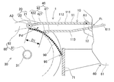
センサ装置40は、駆動装置31により巻き取り方向に移動されるテープ端を検出する。センサ装置40は、規制部41と、光電センサ42とを有する。規制部41は、テープ90のうち押圧装置20により押圧されている部位からテープ90の繰り出し方向に規定距離D1だけ離間して配置され、テープ端の弾性力に抗してテープ端を湾曲させる(図4および図5を参照)。本実施形態において、規制部41は、テープガイド10における本体部11の底壁部113のうちフィーダ60とは反対側の端部に相当する。
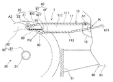
光電センサ42は、テープ端が規制部41を巻き取り方向に通過した場合に(図6を参照)、弾性力によって直線状に復帰したテープ端を検出する。本実施形態において、光電センサ42は、テープガイド10の底壁部113に設けられた発光部421から照射された光を、摩擦ローラ21と並んでテープガイド10の上壁部111に設けられた受光部422により受光する。センサ装置40は、受光部422の受光状態が遮光状態に遷移した場合に、発光部421と受光部422との間にテープ90のテープ端が位置すると認識する。
上記のように、テープ端繰出装置1は、押圧装置20の摩擦ローラ21およびセンサ装置40の規制部41との間において、光電センサ42が検出可能な位置を検出部Pdとして、当該検出部Pdにテープ90のテープ端を検出する。なお、光電センサ42は、発光部421と受光部422を対向して配置する他に、種々の態様を採用し得る。光電センサ42は、例えば発光部421と受光部422を上壁部111または底壁部113に並んで配置され、テープ端により反射される反射光を検出して、または反射板から反射される反射光をテープ端が遮ったことを検出して、テープ端を検出してもよい。
制御装置50は、主として、CPUや各種メモリ、制御回路により構成される。制御装置50は、センサ装置40による検出結果に基づいて駆動装置31および補助駆動部22を制御する。具体的には、制御装置50は、センサ装置40によりテープ端が検出された場合に、駆動装置31によるテープ90の送り移動を停止する。これにより、検出部Pdに検出されたテープ端が導出される。
1-5.テープ端繰出処理
上記のテープ端繰出装置1を用いてテープ90のテープ端95を所定の移動目標まで繰出する処理について、図3-図7を参照して説明する。ここで、フィーダ60は、テープ支持ユニット63にテープ90が支持されていない状態であり、例えばテープ90がレール611の全域に亘って存在していない状態とする。さらに、バケット71には、リール80が収納されている。テープ端繰出装置1は、フィーダ60の後部に取り付けられ、押圧装置20の摩擦ローラ21がリール80に巻回されたテープ90の一部を軸部81側に押圧している状態にある。
上記のテープ端繰出装置1を用いてテープ90のテープ端95を所定の移動目標まで繰出する処理について、図3-図7を参照して説明する。ここで、フィーダ60は、テープ支持ユニット63にテープ90が支持されていない状態であり、例えばテープ90がレール611の全域に亘って存在していない状態とする。さらに、バケット71には、リール80が収納されている。テープ端繰出装置1は、フィーダ60の後部に取り付けられ、押圧装置20の摩擦ローラ21がリール80に巻回されたテープ90の一部を軸部81側に押圧している状態にある。
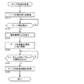
例えばオペレータによりローディング処理の実行を指示する操作スイッチが押されて、またはフィーダ60からの要求を入力して、テープ端繰出装置1が繰出処理を実行する。制御装置50は、先ず、テープ90のうち押圧装置20の摩擦ローラ21により押圧されている部位を巻き取り方向に送り移動させて、テープ90の巻き取りを開始する(ステップ11(以下、「ステップ」を「S」と表記する))。
具体的には、制御装置50は、駆動装置31によりテープ90の巻き取り方向(図4における反時計回り方向)にリール80を回転させる。さらに、制御装置50は、テープ90が巻き取り方向に送り移動されるように、補助駆動部22により摩擦ローラ21を回転させる。制御装置50は、センサ装置40によりテープ端95が検出されない場合には(S12:No)、検出されるまでテープ90の巻き取りを継続する。
これにより、図4に示すように、テープ90のうち直線状に復帰したテープ端95が徐々にテープガイド10の下方に接近する。さらに、テープ90が巻き取られると、テープ端95は、図5に示すように、規制部41により弾性力に抗して湾曲される。その後に、テープ端95が規制部41を巻き取り方向に通過すると、図6に示すように、テープ端95は、弾性力によって直線状に復帰してテープガイド10に挿入された状態となる。
これにより、センサ装置40は、発光部421から照射された光がテープ端95により遮光されて、受光部422の受光状態が遮光状態に遷移したことをもって、テープ端95を検出する。制御装置50は、センサ装置40によりテープ端95が検出された場合には(S12:Yes)、駆動装置31および補助駆動部22を停止する(S13)。このとき、制御装置50は、検出部Pdにテープ端95が検出されているか否かを、受光部422の遮光状態が維持されているか否かに基づいて判定してもよい。
次に、制御装置50は、上記のようにテープ端95が検出された後に、テープ90のうち少なくとも押圧装置20の摩擦ローラ21により押圧されている部位をテープ90の繰り出し方向に送り移動させるように駆動装置31を制御する(S14)。具体的には、制御装置50は、S11における駆動装置31の動作を反転させて、駆動装置31によりテープ90が送出される方向(図4における時計回り方向)にリール80を回転させる。これにより、テープ90は、テープガイド10により案内されて移動目標であるフィーダ60の挿入部Piに向かって送り移動される。
また、上記のような送り移動を行う際に、制御装置50は、テープ90がテープガイド10の内部を送り移動されるように、補助駆動部22により摩擦ローラ21を回転させる。制御装置50は、フィーダ60によるローディング処理が開始されない場合には(S15:No)、ローディング処理が開始されるまでテープ90の送り移動を継続する。これにより、図7に示すように、テープ90がテープガイド10に沿って移動して、テープ端95がフィーダ60の挿入部Piに到達する。
これにより、フィーダ60は、挿入部Piからテープ90が挿入されたことを検出して、一対のスプロケット62によりテープ90をレール611に沿って送り移動させるローディング処理を実行する。制御装置50は、テープ90の引き込みによりローディング処理の開始を検出する。その他に、制御装置50は、例えばフィーダ60や部品装着機からの通知を入力して、ローディング処理の開始を認識してもよい。
フィーダ60によるローディング処理が開始された場合には(S15:Yes)、制御装置50は、駆動装置31および補助駆動部22によるテープ90の自由移動を許容する(S16)。ここで、テープ90の自由移動とは、モータなどによって送り移動を制御するための駆動力を付与されたり制動されたりしておらず、フィーダ60側の動作によってテープ90が移動可能な状態を意味する。
つまり、制御装置50は、リール80および摩擦ローラ21の自由な回転を許容する。このとき、リール80の軸部81から駆動装置31の回転軸が外され、またテープ90から摩擦ローラ21が離間されるようにしてもよい。また、テープ端繰出処理が終了した後に、テープ端繰出装置1は、フィーダ60から取り外され、他のフィーダ60に取り付けられて次回のテープ端繰出処理に用いられるようにしてもよい。このとき、例えばテープガイド10は、延伸方向に底壁部113が分割されて下方に開口し、取り外し可能な状態とされてもよい。
上記のようなテープ端繰出処理を実行することにより、テープ90のテープ端95を自動で検出し、所定の移動目標までテープ端を繰出することができる。これにより、テープ端95の検出および繰出に要する時間を削減できるので、テープ90を用いた作業の効率向上および作業の自動化を図ることができる。また、検出されたテープ端95をフィーダ60の挿入部Piに挿入するように繰出することにより、このようなテープ端95の挿入作業を自動化することができる。よって、部品装着機による装着処理における部品切れを防止して、生産効率の低下を抑制できる。また、挿入作業の自動化によって、生産ラインの省人化を図ることができる。
2.実施形態の変形態様
2-1.テープガイド10について
実施形態において、テープガイド10は、テープ端95が検出される位置(検出部Pd)と、移動目標としてのフィーダ60の挿入部Piを連結する構成とした。これに対して、移動目標は、用途に応じて適宜設定され得る。例えば、移動目標は、異なるテープ90同士を接続するスプライシング装置の挿入部であってもよい。また、スプライシングが手作業にて行われる場合にも、オペレータがテープ端95を取り出す位置を移動目標として設定してもよい。
2-1.テープガイド10について
実施形態において、テープガイド10は、テープ端95が検出される位置(検出部Pd)と、移動目標としてのフィーダ60の挿入部Piを連結する構成とした。これに対して、移動目標は、用途に応じて適宜設定され得る。例えば、移動目標は、異なるテープ90同士を接続するスプライシング装置の挿入部であってもよい。また、スプライシングが手作業にて行われる場合にも、オペレータがテープ端95を取り出す位置を移動目標として設定してもよい。
また、オペレータがテープ端95を取り出す所定の位置は、テープ端95がセンサ装置40により検出される位置(検出部Pd)であってもよい。このような態様においては、テープ端繰出装置1は、テープガイド10および押圧装置20を備えない構成としてもよい。換言すると、実施形態においてテープ端繰出装置1を構成するテープ端検出装置30は、単体で、テープ90のテープ端95を検出する用途に適用することができる。
また、実施形態にて、テープ90は、複数の部品を所定間隔で収納したキャリアテープである態様を例示した。これに対して、テープ端繰出装置1は、側方視において直線状に復帰する弾性力を有し、且つリール80の軸部81に巻回されるものであれば、キャリアテープ以外のテープに適用することができる。また、テープ端検出装置30は、上記のような弾性力を有しないテープ(自重で直線状に復帰しない程度に小さな弾性力を有するテープを含む)であって、且つリール80の軸部81に巻回されるものであれば、キャリアテープ以外のテープに適用することができる。
また、テープ端検出装置30のセンサ装置40は、検出位置(実施形態の「検出部Pd」に相当)をテープ端が通過した際の検出位置におけるテープの厚み方向の変位(「リール80の径方向の変位」に相当)に基づいてテープ端を検出するようにしてもよい。このような構成によると、テープ端検出装置30は、テープの弾性力によらず、巻き取り方向に移動するテープの最外表面の変位(詳細には、リール80の径方向の変位)に基づいてテープ端95を検出できる。
2-2.押圧装置20の係合部について
実施形態において、押圧装置20は、係合部としての摩擦ローラ21を備える構成とした。これに対して、係合部は、回転軸線A2周りに回転可能に設けられ、テープ90と接触する部位においてテープ90と係合する構成であれば、種々の態様を採用し得る。具体的には、押圧装置20の係合部は、テープ90に所定間隔で形成された係合穴912に係合する係合突起を全周に亘って形成されたスプロケットである構成としてもよい。
実施形態において、押圧装置20は、係合部としての摩擦ローラ21を備える構成とした。これに対して、係合部は、回転軸線A2周りに回転可能に設けられ、テープ90と接触する部位においてテープ90と係合する構成であれば、種々の態様を採用し得る。具体的には、押圧装置20の係合部は、テープ90に所定間隔で形成された係合穴912に係合する係合突起を全周に亘って形成されたスプロケットである構成としてもよい。
このような構成によると、係合部としてのスプロケットとテープ90との間に滑りが発生することを防止できる。これにより、テープ端繰出装置1は、テープ90を確実に送り移動させることができる。なお、押圧装置20は、摩擦ローラ21およびスプロケットの両方を備え、テープに応じて一方または両方を用いて、テープ90を軸部81側に押圧しつつテープ90を送り移動させる構成としてもよい。
また、押圧装置20は、上記のように係合部が回転軸線A2周りに回転可能に構成されるものとした。これに対して、押圧装置20は、テープ90を軸部81側に押圧可能であれば、例えばテープ90の上面を摺動する構成としてもよい。但し、係合部とテープ90の摩擦を低減したり、係合部を回転駆動させたりする観点からは、実施形態および変形態様にて例示したように、回転可能な係合部によりテープ90を押圧する構成が好適である。
2-3.駆動装置31について
実施形態において、テープ端繰出装置1は、テープ90を送り移動させる機構として、駆動装置31および補助駆動部22を備える構成とした。これに対して、テープ端繰出装置1は、テープ90のうち少なくとも押圧装置20により押圧されている部位が巻き取り方向に送り移動させることが可能であれば種々の態様を採用し得る。具体的には、テープ端繰出装置1は、駆動装置31および補助駆動部22の一方のみを備える構成としてもよい。
実施形態において、テープ端繰出装置1は、テープ90を送り移動させる機構として、駆動装置31および補助駆動部22を備える構成とした。これに対して、テープ端繰出装置1は、テープ90のうち少なくとも押圧装置20により押圧されている部位が巻き取り方向に送り移動させることが可能であれば種々の態様を採用し得る。具体的には、テープ端繰出装置1は、駆動装置31および補助駆動部22の一方のみを備える構成としてもよい。
つまり、テープ端繰出装置1がリール80に動力を付与する駆動装置31のみを備える構成においては、例えば駆動装置31は、実施形態にて例示したようにリール80の軸部81の動力を付与し、または一対のフランジ部82に少なくとも一方に動力を付与する構成としてもよい。このとき、押圧装置20は、補助駆動部22を有さず、且つ係合部を自由回転可能に支持する。
一方で、テープ端繰出装置1が実施形態にて例示した補助駆動部22のみを備える構成においては、この補助駆動部22が主の駆動装置に相当する。即ち、駆動装置は、係合部としての摩擦ローラ21またはスプロケットに動力を付与する。このとき、リール80は、バケット71に収容され、または軸部81を自由回転可能に支持される。
そのため、駆動装置がテープ90のうち押圧装置20により押圧されている部位を送り移動させると、リール80の回転が伴わなければ、テープ端95が検出されるまでの期間においてテープ90が弛むことになる。しかし、その後にテープ端95が目標位置へと移動されたり、オペレータにより取り出されたりすることによりテープ90の弛みは解消される。このような構成によると、リール80を回転させる機構を省略できるので、テープ端繰出装置1の製造コストを低減できる。また、テープ端繰出装置1をコンパクトにすることができる。
また、テープ端繰出装置1は、実施形態にて例示した駆動装置31および補助駆動部22を一体的にした回転機構を備える構成としてもよい。具体的には、上記の回転機構は、摩擦ローラ21の両端側にリール80の径方向に平行な軸線周りに回転可能であり、且つ一対のフランジ部82の内面にそれぞれ摩擦係合する一対の駆動ローラを備える。これにより、摩擦ローラ21と駆動ローラを適宜回転させることによって、テープ90を送り移動させるとともに、リール80を回転させることができる。
2-4.センサ装置40について
実施形態において、センサ装置40は、規制部41と光電センサ42とを有する構成とした。規制部41は、テープガイド10における本体部11の底壁部113の一部である構成を例示した。これに対して、規制部41は、テープガイド10と別に設けられてもよい。このとき、規制部41は、実施形態と同様にテープ90の上面を摺動する構成の他に、ローラを備える構成としてもよい。また、センサ装置40は、光電センサ42のような非接触式のセンサの他に、規制部41を通過したテープ端95と接触して検出する接触式としてもよい。
実施形態において、センサ装置40は、規制部41と光電センサ42とを有する構成とした。規制部41は、テープガイド10における本体部11の底壁部113の一部である構成を例示した。これに対して、規制部41は、テープガイド10と別に設けられてもよい。このとき、規制部41は、実施形態と同様にテープ90の上面を摺動する構成の他に、ローラを備える構成としてもよい。また、センサ装置40は、光電センサ42のような非接触式のセンサの他に、規制部41を通過したテープ端95と接触して検出する接触式としてもよい。
1:テープ端繰出装置、 10:テープガイド、 20:押圧装置、 21:摩擦ローラ(係合部)、 22:補助駆動部、 30:テープ端検出装置、 31:駆動装置、 40:センサ装置、 41:規制部、 42:光電センサ、 50:制御装置、 60:フィーダ、 71:バケット、 80:リール、 81:軸部、 82:フランジ部、 90:キャリアテープ、 912:係合穴、 95:テープ端、 Pi:挿入部(移動目標)、 Pd:検出部、 A1:(テープガイドの)回転軸線、 A2:(摩擦ローラの)回転軸線
Claims (13)
- リールの軸部に巻回されたテープのテープ端を検出するテープ端検出装置であって、
前記テープの少なくとも一部を巻き取り方向に送り移動させる駆動装置と、
前記駆動装置により巻き取り方向に移動される前記テープのテープ端を検出するセンサ装置と、
前記センサ装置による検出結果に基づいて前記駆動装置を制御する制御装置と、
を備えるテープ端検出装置。 - 前記センサ装置は、検出位置を前記テープ端が通過した際の前記検出位置における前記テープの厚み方向の変位に基づいて前記テープ端を検出する、請求項1に記載のテープ端検出装置。
- 前記テープは、直線状に復帰する弾性力に抗して前記軸部に巻回され、
前記テープ端を所定の移動目標まで繰出するテープ端繰出装置であって、
請求項1または2に記載のテープ端検出装置と、
前記軸部側に前記テープを押圧する押圧装置と、を備え、
前記駆動装置は、前記テープのうち少なくとも前記押圧装置により押圧されている部位を巻き取り方向に送り移動させる、テープ端繰出装置。 - 前記制御装置は、前記センサ装置により前記テープ端が検出された場合に、前記駆動装置による前記テープの送り移動を停止する、請求項3に記載のテープ端繰出装置。
- 前記テープ端繰出装置は、前記テープ端が繰出される位置から前記移動目標まで前記テープの送り移動をガイドするテープガイドをさらに備え、
前記制御装置は、前記テープ端が検出された後に、前記テープのうち少なくとも前記押圧装置により押圧されている部位を前記テープの繰り出し方向に送り移動させるように前記駆動装置を制御することによって、前記移動目標に向かって前記テープを送り移動させる、請求項4に記載のテープ端繰出装置。 - 前記テープは、複数の部品を所定間隔で収納したキャリアテープであり、
前記テープガイドは、前記キャリアテープを自動で装填可能なオートローディング式のフィーダにおける前記キャリアテープの挿入部を前記移動目標として、前記テープ端が検出される位置と前記挿入部を連結する、請求項5に記載のテープ端繰出装置。 - 前記押圧装置は、前記軸部と平行な軸線周りに回転可能に設けられ、前記テープと接触する部位において前記テープと係合する係合部を有する、請求項3-6の何れか一項に記載のテープ端繰出装置。
- 前記係合部は、前記テープと摩擦係合する摩擦ローラである、請求項7に記載のテープ端繰出装置。
- 前記係合部は、前記テープに所定間隔で形成された係合穴に係合する係合突起を全周に亘って形成されたスプロケットである、請求項7に記載のテープ端繰出装置。
- 前記押圧装置は、前記係合部を回転駆動させて前記テープの送り移動を補助する補助駆動部をさらに有する、請求項7-9の何れか一項に記載のテープ端繰出装置。
- 前記駆動装置は、前記係合部を回転駆動させて前記テープを送り移動させる、請求項7-9の何れか一項に記載のテープ端繰出装置。
- 前記駆動装置は、前記リールの前記軸部またはフランジ部に動力を付与して前記リールを回転駆動させて前記テープを送り移動させる、請求項3-11の何れか一項に記載のテープ端繰出装置。
- 前記センサ装置は、
前記テープのうち前記押圧装置により押圧されている部位から前記テープの繰り出し方向に規定距離だけ離間して配置され、前記テープ端の弾性力に抗して前記テープ端を湾曲させる規制部と、
前記テープ端が前記規制部を巻き取り方向に通過した場合に、弾性力によって直線状に復帰した前記テープ端を検出する光電センサと、を有する、請求項3-12の何れか一項に記載のテープ端繰出装置。
Priority Applications (2)
| Application Number | Priority Date | Filing Date | Title |
|---|---|---|---|
| PCT/JP2017/028360 WO2019026271A1 (ja) | 2017-08-04 | 2017-08-04 | テープ端検出装置およびテープ端繰出装置 |
| JP2019533855A JP6899908B2 (ja) | 2017-08-04 | 2017-08-04 | テープ端繰出装置 |
Applications Claiming Priority (1)
| Application Number | Priority Date | Filing Date | Title |
|---|---|---|---|
| PCT/JP2017/028360 WO2019026271A1 (ja) | 2017-08-04 | 2017-08-04 | テープ端検出装置およびテープ端繰出装置 |
Publications (1)
| Publication Number | Publication Date |
|---|---|
| WO2019026271A1 true WO2019026271A1 (ja) | 2019-02-07 |
Family
ID=65233693
Family Applications (1)
| Application Number | Title | Priority Date | Filing Date |
|---|---|---|---|
| PCT/JP2017/028360 Ceased WO2019026271A1 (ja) | 2017-08-04 | 2017-08-04 | テープ端検出装置およびテープ端繰出装置 |
Country Status (2)
| Country | Link |
|---|---|
| JP (1) | JP6899908B2 (ja) |
| WO (1) | WO2019026271A1 (ja) |
Citations (5)
| Publication number | Priority date | Publication date | Assignee | Title |
|---|---|---|---|---|
| JPH05246610A (ja) * | 1992-03-04 | 1993-09-24 | Ricoh Co Ltd | ロール紙先端検知手段を備えた給紙装置 |
| JP2005060017A (ja) * | 2003-08-11 | 2005-03-10 | Shinko Electric Co Ltd | 印刷用紙供給機構および印刷装置 |
| US20130161369A1 (en) * | 2011-12-22 | 2013-06-27 | Hiti Digital, Inc. | Automatic document feeding mechanism adapted to a paper roll and thermal sublimation printer therewith |
| WO2016147425A1 (ja) * | 2015-03-18 | 2016-09-22 | 富士機械製造株式会社 | フィーダ装置、および部品実装機 |
| JP2017135208A (ja) * | 2016-01-26 | 2017-08-03 | パナソニックIpマネジメント株式会社 | テープフィーダ及び部品実装装置 |
Family Cites Families (1)
| Publication number | Priority date | Publication date | Assignee | Title |
|---|---|---|---|---|
| JPS62246030A (ja) * | 1986-04-19 | 1987-10-27 | Minolta Camera Co Ltd | ロ−ルフイルム送り出し装置 |
-
2017
- 2017-08-04 WO PCT/JP2017/028360 patent/WO2019026271A1/ja not_active Ceased
- 2017-08-04 JP JP2019533855A patent/JP6899908B2/ja active Active
Patent Citations (5)
| Publication number | Priority date | Publication date | Assignee | Title |
|---|---|---|---|---|
| JPH05246610A (ja) * | 1992-03-04 | 1993-09-24 | Ricoh Co Ltd | ロール紙先端検知手段を備えた給紙装置 |
| JP2005060017A (ja) * | 2003-08-11 | 2005-03-10 | Shinko Electric Co Ltd | 印刷用紙供給機構および印刷装置 |
| US20130161369A1 (en) * | 2011-12-22 | 2013-06-27 | Hiti Digital, Inc. | Automatic document feeding mechanism adapted to a paper roll and thermal sublimation printer therewith |
| WO2016147425A1 (ja) * | 2015-03-18 | 2016-09-22 | 富士機械製造株式会社 | フィーダ装置、および部品実装機 |
| JP2017135208A (ja) * | 2016-01-26 | 2017-08-03 | パナソニックIpマネジメント株式会社 | テープフィーダ及び部品実装装置 |
Also Published As
| Publication number | Publication date |
|---|---|
| JPWO2019026271A1 (ja) | 2020-04-09 |
| JP6899908B2 (ja) | 2021-07-07 |
Similar Documents
| Publication | Publication Date | Title |
|---|---|---|
| JP7527117B2 (ja) | 給送装置、記録装置及び給送装置の制御方法 | |
| JPH0550428B2 (ja) | ||
| JP2007254156A (ja) | 光ファイバ再巻取り装置 | |
| JP2015115412A (ja) | 部品供給装置および部品供給方法 | |
| JP3935579B2 (ja) | カバーテープ送り装置,カバーテープ処理装置およびフィーダユニット | |
| JP7158176B2 (ja) | テープ自動装填装置 | |
| CN1332594C (zh) | 电子部件供给盒用控带盘支撑装置 | |
| JP7096005B2 (ja) | テープ巻き取り装置 | |
| JP7398756B2 (ja) | 部品供給装置 | |
| JP6899908B2 (ja) | テープ端繰出装置 | |
| JP4485220B2 (ja) | 深絞り包装機用フィルム自動供給装置 | |
| JP2015024874A (ja) | シート切断装置 | |
| EP2567921B1 (en) | Winding unit | |
| JP7510368B2 (ja) | テープ繰出装置、貼付装置 | |
| JP7470475B2 (ja) | 部品実装機 | |
| JP7761748B2 (ja) | テープ搬送補助装置及びテープ自動装填装置 | |
| JP2019033301A (ja) | フィーダ | |
| JP6448544B2 (ja) | フィーダ | |
| JP7667653B2 (ja) | シート繰り出し装置 | |
| JP6782468B2 (ja) | 部品供給装置 | |
| JP5245090B2 (ja) | 糊付け装置 | |
| US12552631B2 (en) | Sheet bundle binding apparatus and rotation detection method | |
| JP6731674B2 (ja) | 部品供給装置 | |
| JP7694082B2 (ja) | 搬送ユニット及びレーザーマーキング装置 | |
| KR102789999B1 (ko) | 사료 이송 구동 장치 |
Legal Events
| Date | Code | Title | Description |
|---|---|---|---|
| 121 | Ep: the epo has been informed by wipo that ep was designated in this application |
Ref document number: 17920476 Country of ref document: EP Kind code of ref document: A1 |
|
| ENP | Entry into the national phase |
Ref document number: 2019533855 Country of ref document: JP Kind code of ref document: A |
|
| NENP | Non-entry into the national phase |
Ref country code: DE |
|
| 122 | Ep: pct application non-entry in european phase |
Ref document number: 17920476 Country of ref document: EP Kind code of ref document: A1 |