WO2019021886A1 - 電線溶着装置 - Google Patents
電線溶着装置 Download PDFInfo
- Publication number
- WO2019021886A1 WO2019021886A1 PCT/JP2018/026743 JP2018026743W WO2019021886A1 WO 2019021886 A1 WO2019021886 A1 WO 2019021886A1 JP 2018026743 W JP2018026743 W JP 2018026743W WO 2019021886 A1 WO2019021886 A1 WO 2019021886A1
- Authority
- WO
- WIPO (PCT)
- Prior art keywords
- sheet
- wire
- anvil
- electric wire
- moving
- Prior art date
Links
Images


Classifications
-
- B—PERFORMING OPERATIONS; TRANSPORTING
- B29—WORKING OF PLASTICS; WORKING OF SUBSTANCES IN A PLASTIC STATE IN GENERAL
- B29C—SHAPING OR JOINING OF PLASTICS; SHAPING OF MATERIAL IN A PLASTIC STATE, NOT OTHERWISE PROVIDED FOR; AFTER-TREATMENT OF THE SHAPED PRODUCTS, e.g. REPAIRING
- B29C66/00—General aspects of processes or apparatus for joining preformed parts
- B29C66/69—General aspects of joining filaments
-
- B—PERFORMING OPERATIONS; TRANSPORTING
- B29—WORKING OF PLASTICS; WORKING OF SUBSTANCES IN A PLASTIC STATE IN GENERAL
- B29C—SHAPING OR JOINING OF PLASTICS; SHAPING OF MATERIAL IN A PLASTIC STATE, NOT OTHERWISE PROVIDED FOR; AFTER-TREATMENT OF THE SHAPED PRODUCTS, e.g. REPAIRING
- B29C65/00—Joining or sealing of preformed parts, e.g. welding of plastics materials; Apparatus therefor
- B29C65/02—Joining or sealing of preformed parts, e.g. welding of plastics materials; Apparatus therefor by heating, with or without pressure
- B29C65/08—Joining or sealing of preformed parts, e.g. welding of plastics materials; Apparatus therefor by heating, with or without pressure using ultrasonic vibrations
- B29C65/083—Joining or sealing of preformed parts, e.g. welding of plastics materials; Apparatus therefor by heating, with or without pressure using ultrasonic vibrations using a rotary sonotrode or a rotary anvil
- B29C65/086—Joining or sealing of preformed parts, e.g. welding of plastics materials; Apparatus therefor by heating, with or without pressure using ultrasonic vibrations using a rotary sonotrode or a rotary anvil using a rotary anvil
-
- B—PERFORMING OPERATIONS; TRANSPORTING
- B29—WORKING OF PLASTICS; WORKING OF SUBSTANCES IN A PLASTIC STATE IN GENERAL
- B29C—SHAPING OR JOINING OF PLASTICS; SHAPING OF MATERIAL IN A PLASTIC STATE, NOT OTHERWISE PROVIDED FOR; AFTER-TREATMENT OF THE SHAPED PRODUCTS, e.g. REPAIRING
- B29C65/00—Joining or sealing of preformed parts, e.g. welding of plastics materials; Apparatus therefor
- B29C65/78—Means for handling the parts to be joined, e.g. for making containers or hollow articles, e.g. means for handling sheets, plates, web-like materials, tubular articles, hollow articles or elements to be joined therewith; Means for discharging the joined articles from the joining apparatus
- B29C65/7841—Holding or clamping means for handling purposes
-
- B—PERFORMING OPERATIONS; TRANSPORTING
- B29—WORKING OF PLASTICS; WORKING OF SUBSTANCES IN A PLASTIC STATE IN GENERAL
- B29C—SHAPING OR JOINING OF PLASTICS; SHAPING OF MATERIAL IN A PLASTIC STATE, NOT OTHERWISE PROVIDED FOR; AFTER-TREATMENT OF THE SHAPED PRODUCTS, e.g. REPAIRING
- B29C66/00—General aspects of processes or apparatus for joining preformed parts
- B29C66/01—General aspects dealing with the joint area or with the area to be joined
- B29C66/05—Particular design of joint configurations
- B29C66/10—Particular design of joint configurations particular design of the joint cross-sections
- B29C66/11—Joint cross-sections comprising a single joint-segment, i.e. one of the parts to be joined comprising a single joint-segment in the joint cross-section
- B29C66/112—Single lapped joints
- B29C66/1122—Single lap to lap joints, i.e. overlap joints
-
- B—PERFORMING OPERATIONS; TRANSPORTING
- B29—WORKING OF PLASTICS; WORKING OF SUBSTANCES IN A PLASTIC STATE IN GENERAL
- B29C—SHAPING OR JOINING OF PLASTICS; SHAPING OF MATERIAL IN A PLASTIC STATE, NOT OTHERWISE PROVIDED FOR; AFTER-TREATMENT OF THE SHAPED PRODUCTS, e.g. REPAIRING
- B29C66/00—General aspects of processes or apparatus for joining preformed parts
- B29C66/01—General aspects dealing with the joint area or with the area to be joined
- B29C66/05—Particular design of joint configurations
- B29C66/20—Particular design of joint configurations particular design of the joint lines, e.g. of the weld lines
- B29C66/21—Particular design of joint configurations particular design of the joint lines, e.g. of the weld lines said joint lines being formed by a single dot or dash or by several dots or dashes, i.e. spot joining or spot welding
-
- B—PERFORMING OPERATIONS; TRANSPORTING
- B29—WORKING OF PLASTICS; WORKING OF SUBSTANCES IN A PLASTIC STATE IN GENERAL
- B29C—SHAPING OR JOINING OF PLASTICS; SHAPING OF MATERIAL IN A PLASTIC STATE, NOT OTHERWISE PROVIDED FOR; AFTER-TREATMENT OF THE SHAPED PRODUCTS, e.g. REPAIRING
- B29C66/00—General aspects of processes or apparatus for joining preformed parts
- B29C66/01—General aspects dealing with the joint area or with the area to be joined
- B29C66/05—Particular design of joint configurations
- B29C66/20—Particular design of joint configurations particular design of the joint lines, e.g. of the weld lines
- B29C66/24—Particular design of joint configurations particular design of the joint lines, e.g. of the weld lines said joint lines being closed or non-straight
- B29C66/244—Particular design of joint configurations particular design of the joint lines, e.g. of the weld lines said joint lines being closed or non-straight said joint lines being non-straight, e.g. forming non-closed contours
-
- B—PERFORMING OPERATIONS; TRANSPORTING
- B29—WORKING OF PLASTICS; WORKING OF SUBSTANCES IN A PLASTIC STATE IN GENERAL
- B29C—SHAPING OR JOINING OF PLASTICS; SHAPING OF MATERIAL IN A PLASTIC STATE, NOT OTHERWISE PROVIDED FOR; AFTER-TREATMENT OF THE SHAPED PRODUCTS, e.g. REPAIRING
- B29C66/00—General aspects of processes or apparatus for joining preformed parts
- B29C66/40—General aspects of joining substantially flat articles, e.g. plates, sheets or web-like materials; Making flat seams in tubular or hollow articles; Joining single elements to substantially flat surfaces
- B29C66/47—Joining single elements to sheets, plates or other substantially flat surfaces
-
- B—PERFORMING OPERATIONS; TRANSPORTING
- B29—WORKING OF PLASTICS; WORKING OF SUBSTANCES IN A PLASTIC STATE IN GENERAL
- B29C—SHAPING OR JOINING OF PLASTICS; SHAPING OF MATERIAL IN A PLASTIC STATE, NOT OTHERWISE PROVIDED FOR; AFTER-TREATMENT OF THE SHAPED PRODUCTS, e.g. REPAIRING
- B29C66/00—General aspects of processes or apparatus for joining preformed parts
- B29C66/70—General aspects of processes or apparatus for joining preformed parts characterised by the composition, physical properties or the structure of the material of the parts to be joined; Joining with non-plastics material
- B29C66/73—General aspects of processes or apparatus for joining preformed parts characterised by the composition, physical properties or the structure of the material of the parts to be joined; Joining with non-plastics material characterised by the intensive physical properties of the material of the parts to be joined, by the optical properties of the material of the parts to be joined, by the extensive physical properties of the parts to be joined, by the state of the material of the parts to be joined or by the material of the parts to be joined being a thermoplastic or a thermoset
- B29C66/739—General aspects of processes or apparatus for joining preformed parts characterised by the composition, physical properties or the structure of the material of the parts to be joined; Joining with non-plastics material characterised by the intensive physical properties of the material of the parts to be joined, by the optical properties of the material of the parts to be joined, by the extensive physical properties of the parts to be joined, by the state of the material of the parts to be joined or by the material of the parts to be joined being a thermoplastic or a thermoset characterised by the material of the parts to be joined being a thermoplastic or a thermoset
- B29C66/7392—General aspects of processes or apparatus for joining preformed parts characterised by the composition, physical properties or the structure of the material of the parts to be joined; Joining with non-plastics material characterised by the intensive physical properties of the material of the parts to be joined, by the optical properties of the material of the parts to be joined, by the extensive physical properties of the parts to be joined, by the state of the material of the parts to be joined or by the material of the parts to be joined being a thermoplastic or a thermoset characterised by the material of the parts to be joined being a thermoplastic or a thermoset characterised by the material of at least one of the parts being a thermoplastic
- B29C66/73921—General aspects of processes or apparatus for joining preformed parts characterised by the composition, physical properties or the structure of the material of the parts to be joined; Joining with non-plastics material characterised by the intensive physical properties of the material of the parts to be joined, by the optical properties of the material of the parts to be joined, by the extensive physical properties of the parts to be joined, by the state of the material of the parts to be joined or by the material of the parts to be joined being a thermoplastic or a thermoset characterised by the material of the parts to be joined being a thermoplastic or a thermoset characterised by the material of at least one of the parts being a thermoplastic characterised by the materials of both parts being thermoplastics
-
- B—PERFORMING OPERATIONS; TRANSPORTING
- B29—WORKING OF PLASTICS; WORKING OF SUBSTANCES IN A PLASTIC STATE IN GENERAL
- B29C—SHAPING OR JOINING OF PLASTICS; SHAPING OF MATERIAL IN A PLASTIC STATE, NOT OTHERWISE PROVIDED FOR; AFTER-TREATMENT OF THE SHAPED PRODUCTS, e.g. REPAIRING
- B29C66/00—General aspects of processes or apparatus for joining preformed parts
- B29C66/80—General aspects of machine operations or constructions and parts thereof
- B29C66/81—General aspects of the pressing elements, i.e. the elements applying pressure on the parts to be joined in the area to be joined, e.g. the welding jaws or clamps
- B29C66/814—General aspects of the pressing elements, i.e. the elements applying pressure on the parts to be joined in the area to be joined, e.g. the welding jaws or clamps characterised by the design of the pressing elements, e.g. of the welding jaws or clamps
- B29C66/8141—General aspects of the pressing elements, i.e. the elements applying pressure on the parts to be joined in the area to be joined, e.g. the welding jaws or clamps characterised by the design of the pressing elements, e.g. of the welding jaws or clamps characterised by the surface geometry of the part of the pressing elements, e.g. welding jaws or clamps, coming into contact with the parts to be joined
- B29C66/81431—General aspects of the pressing elements, i.e. the elements applying pressure on the parts to be joined in the area to be joined, e.g. the welding jaws or clamps characterised by the design of the pressing elements, e.g. of the welding jaws or clamps characterised by the surface geometry of the part of the pressing elements, e.g. welding jaws or clamps, coming into contact with the parts to be joined comprising a single cavity, e.g. a groove
-
- B—PERFORMING OPERATIONS; TRANSPORTING
- B29—WORKING OF PLASTICS; WORKING OF SUBSTANCES IN A PLASTIC STATE IN GENERAL
- B29C—SHAPING OR JOINING OF PLASTICS; SHAPING OF MATERIAL IN A PLASTIC STATE, NOT OTHERWISE PROVIDED FOR; AFTER-TREATMENT OF THE SHAPED PRODUCTS, e.g. REPAIRING
- B29C66/00—General aspects of processes or apparatus for joining preformed parts
- B29C66/80—General aspects of machine operations or constructions and parts thereof
- B29C66/83—General aspects of machine operations or constructions and parts thereof characterised by the movement of the joining or pressing tools
- B29C66/836—Moving relative to and tangentially to the parts to be joined, e.g. transversely to the displacement of the parts to be joined, e.g. using a X-Y table
- B29C66/8362—Rollers, cylinders or drums moving relative to and tangentially to the parts to be joined
-
- B—PERFORMING OPERATIONS; TRANSPORTING
- B29—WORKING OF PLASTICS; WORKING OF SUBSTANCES IN A PLASTIC STATE IN GENERAL
- B29C—SHAPING OR JOINING OF PLASTICS; SHAPING OF MATERIAL IN A PLASTIC STATE, NOT OTHERWISE PROVIDED FOR; AFTER-TREATMENT OF THE SHAPED PRODUCTS, e.g. REPAIRING
- B29C66/00—General aspects of processes or apparatus for joining preformed parts
- B29C66/80—General aspects of machine operations or constructions and parts thereof
- B29C66/84—Specific machine types or machines suitable for specific applications
- B29C66/843—Machines for making separate joints at the same time in different planes; Machines for making separate joints at the same time mounted in parallel or in series
- B29C66/8432—Machines for making separate joints at the same time mounted in parallel or in series
-
- H—ELECTRICITY
- H01—ELECTRIC ELEMENTS
- H01B—CABLES; CONDUCTORS; INSULATORS; SELECTION OF MATERIALS FOR THEIR CONDUCTIVE, INSULATING OR DIELECTRIC PROPERTIES
- H01B13/00—Apparatus or processes specially adapted for manufacturing conductors or cables
-
- H—ELECTRICITY
- H01—ELECTRIC ELEMENTS
- H01B—CABLES; CONDUCTORS; INSULATORS; SELECTION OF MATERIALS FOR THEIR CONDUCTIVE, INSULATING OR DIELECTRIC PROPERTIES
- H01B13/00—Apparatus or processes specially adapted for manufacturing conductors or cables
- H01B13/012—Apparatus or processes specially adapted for manufacturing conductors or cables for manufacturing wire harnesses
-
- B—PERFORMING OPERATIONS; TRANSPORTING
- B29—WORKING OF PLASTICS; WORKING OF SUBSTANCES IN A PLASTIC STATE IN GENERAL
- B29C—SHAPING OR JOINING OF PLASTICS; SHAPING OF MATERIAL IN A PLASTIC STATE, NOT OTHERWISE PROVIDED FOR; AFTER-TREATMENT OF THE SHAPED PRODUCTS, e.g. REPAIRING
- B29C66/00—General aspects of processes or apparatus for joining preformed parts
- B29C66/70—General aspects of processes or apparatus for joining preformed parts characterised by the composition, physical properties or the structure of the material of the parts to be joined; Joining with non-plastics material
- B29C66/71—General aspects of processes or apparatus for joining preformed parts characterised by the composition, physical properties or the structure of the material of the parts to be joined; Joining with non-plastics material characterised by the composition of the plastics material of the parts to be joined
-
- B—PERFORMING OPERATIONS; TRANSPORTING
- B29—WORKING OF PLASTICS; WORKING OF SUBSTANCES IN A PLASTIC STATE IN GENERAL
- B29C—SHAPING OR JOINING OF PLASTICS; SHAPING OF MATERIAL IN A PLASTIC STATE, NOT OTHERWISE PROVIDED FOR; AFTER-TREATMENT OF THE SHAPED PRODUCTS, e.g. REPAIRING
- B29C66/00—General aspects of processes or apparatus for joining preformed parts
- B29C66/70—General aspects of processes or apparatus for joining preformed parts characterised by the composition, physical properties or the structure of the material of the parts to be joined; Joining with non-plastics material
- B29C66/72—General aspects of processes or apparatus for joining preformed parts characterised by the composition, physical properties or the structure of the material of the parts to be joined; Joining with non-plastics material characterised by the structure of the material of the parts to be joined
- B29C66/729—Textile or other fibrous material made from plastics
- B29C66/7294—Non woven mats, e.g. felt
-
- B—PERFORMING OPERATIONS; TRANSPORTING
- B29—WORKING OF PLASTICS; WORKING OF SUBSTANCES IN A PLASTIC STATE IN GENERAL
- B29L—INDEXING SCHEME ASSOCIATED WITH SUBCLASS B29C, RELATING TO PARTICULAR ARTICLES
- B29L2031/00—Other particular articles
- B29L2031/34—Electrical apparatus, e.g. sparking plugs or parts thereof
- B29L2031/3462—Cables
-
- H—ELECTRICITY
- H01—ELECTRIC ELEMENTS
- H01B—CABLES; CONDUCTORS; INSULATORS; SELECTION OF MATERIALS FOR THEIR CONDUCTIVE, INSULATING OR DIELECTRIC PROPERTIES
- H01B13/00—Apparatus or processes specially adapted for manufacturing conductors or cables
- H01B13/22—Sheathing; Armouring; Screening; Applying other protective layers
- H01B13/26—Sheathing; Armouring; Screening; Applying other protective layers by winding, braiding or longitudinal lapping
- H01B13/2613—Sheathing; Armouring; Screening; Applying other protective layers by winding, braiding or longitudinal lapping by longitudinal lapping
- H01B13/2633—Bending and welding of a metallic screen
- H01B13/264—Details of the welding stage
Definitions
- the present invention relates to a wire welding apparatus.
- a wire harness wired to a car may be attached to a vehicle body panel via a clamp having a locking blade.
- the clamps are attached at intervals in the longitudinal direction of the wire harness, and the wire harness is attached to the vehicle body panel by inserting the locking vanes into mounting holes provided in advance in the vehicle body panel.
- the wire harness is attached to the vehicle-side fixing member via a double-sided adhesive tape or a hook-and-loop fastener.
- the wire harness disclosed in JP2015-90783A is assembled in the following procedure. First, in the wire harness assembly line, a sheet capable of heat welding is placed on a work bench with the side surface facing up. Next, a worker sets the wire group in the central adhesive portion of the sheet. Next, both sides of the central adhesive portion of the sheet are wound on the upper surface side of the wire group and the both sides of the sheet are overlapped. Thus, the wire harness is assembled with the sheet wound at a predetermined position in the longitudinal direction of the wire group.
- the assembled wire harness is then transported to a car assembly line.
- a wire harness is routed along the inner surface of the ceiling side of a vehicle-side fixing member that is the lining material of the automobile.
- the sheet is welded and fixed to the vehicle body side fixing material at a predetermined position using an ultrasonic welding tool, whereby the wire harness is attached to the vehicle body side fixing material.
- the wire group may be fixed to the sheet fixed to the vehicle-side fixing member, and the sheet does not have to be wound around the wire group. Therefore, if this winding operation can be omitted, it is possible to further automate and avoid an increase in the manufacturing cost of the wire harness, which is preferable.
- An object of the present invention is to secure a sheet which can be secured to a fixing material without damaging the electric wire.
- the wire welding apparatus comprises a sheet supporting means for supporting the ultrasonic weldable sheet so that a part or all of the sheet is horizontal, and a wire on the upper surface of the sheet.
- An electric wire supply means for supplying, an anvil for pressing an electric wire supplied to the upper surface of the sheet from above, and an ultrasonic wave for opposing the anvil to the lower surface of the sheet and sandwiching the sheet and electric wire with the anvil And a horn.
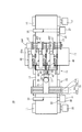
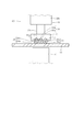
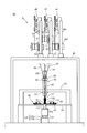
- FIG. 1 is a front view of a wire welding apparatus according to a first embodiment of the present invention.
- FIG. 2 is a top view of the wire welding apparatus.
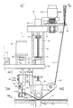
- FIG. 3 is a cross-sectional view taken along line III-III of FIG.
- FIG. 4 is an enlarged view of a portion IV of FIG. 1 showing the periphery of the anvil.
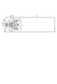
- FIG. 5 is a cross-sectional view taken along the line V-V in FIG. 4 and shows a state in which the end of the electric wire is welded to the sheet-like material.
- FIG. 6 is a top view showing a state in which the electric wires are sequentially welded to the sheet, corresponding to FIG.
- FIG. 7 is a cross-sectional view taken along the line VII-VII in FIG.
- FIG. 6 shows a state in which the electric wire is supplied to the upper surface of the sheet-like material.
- FIG. 8 is a cross-sectional view corresponding to FIG. 7 showing a state in which the electric wire is welded to the sheet-like material.
- FIG. 9 is a top view showing a wire harness obtained by intermittently welding an electric wire to a sheet-like material.
- FIG. 10 is a view corresponding to FIG. 9 and showing a wire harness obtained by continuously welding the electric wire to the sheet-like material.
- FIG. 11 is a top view showing another wire harness including a wire which is bent and welded to a sheet-like material.
- FIG. 12 is an enlarged top view of a portion XII of FIG.
- FIG. 11 shows a state in which the wire is welded to a sheet while curving.
- FIG. 13 is a cross-sectional view corresponding to FIG. 8 showing a state in which a plurality of electric wires having different outer diameters are welded to the sheet-like material.
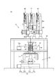
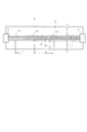
- FIG. 14 is a front view of a wire welding apparatus according to a second embodiment of the present invention.
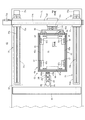
- FIG. 15 is a cross-sectional view taken along line XV-XV of FIG.
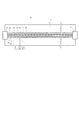
- FIG. 16 is a cross-sectional view taken along line XVI-XVI in FIG.
- FIG. 17 is a cross-sectional view taken along line XVII-XVII in FIG. 16 and shows a frame member.
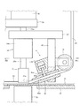
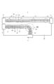
- FIG. 18 is an enlarged view of a portion XVIII in FIG.
- FIG. 14 shows the periphery of the anvil.
- FIG. 19 is a cross-sectional view taken along line XIX-XIX in FIG. 18, and shows a clamp device and a cutter device.
- FIG. 20 is a cross-sectional view taken along line XX-XX in FIG. 18, and shows a guide member.
- FIG. 21 is a view corresponding to FIG. 18 showing a state where the anvil and the guide member are rotated 90 degrees.
- FIG. 22 is a cross-sectional view taken along the line XXII-XXII in FIG. 18, and shows a state in which the end of the electric wire is welded to the sheet.
- FIG. 23 is a top view showing a state in which the electric wire is continuously and linearly welded to the sheet, corresponding to FIG.
- FIG. 24 is a top view corresponding to FIG. 23, showing a state in which a wire is newly welded across a linear wire.
- FIG. 25 is a top view corresponding to FIG. 24 showing a state in which the electric wire is welded in a U-shape by rotating the anvil by 180 degrees.
- the wire welding apparatus 10 includes a sheet support means 12 for supporting the ultrasonic weldable sheet 11 so that a part or all of the sheet 11 is horizontal.
- the sheet support means 12 supports a part of the elongated sheet-like material 11 so as to be horizontal.
- the sheet supporting means 12 includes a horizontal plate 13 on which a part of the sheet-like material 11 is placed on the upper surface, a pair of winding rollers 14 and 15 provided on both sides of the horizontal plate 13, And a pair of winding motors 16 and 17 for rotating the winding rollers 14 and 15 separately.
- the pair of winding rollers 14 and 15 are provided in parallel to each other, and wind the both sides in the longitudinal direction of the sheet 11 protruding from both ends of the horizontal plate 13.
- the sheet-like material 11 can be welded to another member by the vibration of the ultrasonic horn 51 described later.
- a film made of a resin such as PVC (polyvinyl chloride), PE (polyethylene), PP (polypropylene) or the like, a nonwoven fabric made of these resins, or the like can be used.
- the wire welding device 10 includes a sheet moving unit 21 that moves a part or all of the horizontal portion of the sheet 11 in the horizontal direction.
- the sheet moving means 21 includes a pair of movable rollers 22 and 23 provided in the vicinity of the end on both sides of the horizontal plate 13, and a pair of holding rollers 24 and 25 sandwiching the sheet 11 together with the pair of movable rollers 22 and 23; A pair of drive motors 26, 27 for rotating the pair of movable rollers 22, 23 are provided.
- the sheet-like material 11 protruding from the end of the horizontal plate 13 is placed on the pair of movable rollers 22 and 23.
- the sheet moving unit 21 moves the long sheet 11 in the longitudinal direction by synchronously rotating the pair of movable rollers 22 and 23 at the same speed in the same direction by the pair of drive motors 26 and 27.
- the winding roller 14 or 15 on the rear side in the moving direction of the sheet 11 takes the sheet 11 that has already been wound along with the movement of the sheet 11. Rotate to unroll.
- the winding roller 14 or 15 located forward in the moving direction rotates so as to wind the sheet 11 anew.
- the wire welding device 10 includes an anvil 31 as a pressing tool for pressing the plurality of wires 30 supplied to the upper surface of the sheet 11 from above.
- three electric wires 30 are supplied to the upper surface of the sheet 11 as shown in FIG.
- the number of electric wires 30 is not limited to three, as long as at least one electric wire 30 is supplied to the upper surface of the sheet-like material 11.
- the wire 30 is a so-called insulated wire including a core wire 30 a and an insulating coating 30 b covering the core wire 30 a.
- Core wire 30a is formed of a conductive material such as copper or aluminum.
- the core wire 30a may be a single wire or may be a stranded wire.
- the electric wire 30 is formed on the sheet 11 so as to be capable of ultrasonic welding.
- the insulation coating 30b of the electric wire 30 is made of, for example, ultrasonic weldable resin such as PVC (polyvinyl chloride), PE (polyethylene), PP (polypropylene), etc.
- the insulation coating 30b is a sheet by ultrasonic welding. It is welded to the rod 11.
- the electric wire 30 is formed by extrusion molding.
- the material of the insulating coating 30b is not limited to the resin, and may be a material that can be ultrasonically welded, and may be, for example, a varnish or the like.
- the varnish or the like is applied to the outer periphery of the core wire 30a and baked.
- the rotational moving means 32 includes an upper telescopic actuator 33 as an anvil moving means for moving the anvil 31 in the width direction of the sheet 11 above the horizontal plate 13.
- the upper telescopic actuator 33 includes a ball screw 33 b rotationally driven by a servo motor 33 a and a follower 33 c screwed to the ball screw 33 b.
- the housing 33 d of the upper telescopic actuator 33 is provided above the horizontal plate 13 so as to extend in the width direction of the sheet 11.
- the ball screw 33 b extends in the width direction of the sheet 11, and the follower 33 c moves in the width direction of the sheet 11 by the rotation of the ball screw 33 b.
- a movable plate 34 extending in the longitudinal direction of the sheet 11 is attached to the side of the housing 33 d at the follower 33 c.
- a rotation motor 36 as an anvil rotation means is attached to the movable plate 34 in a state where the rotation shaft 36 a is protruded downward.
- An anvil 31 is attached to the rotation shaft 36a via an intermediate plate 37 and an upper fluid pressure cylinder 38 as lifting means.
- the intermediate plate 37 is provided substantially horizontally.
- the upper hydraulic cylinder 38 comprises a rod 38a which moves relative to the body 38b by the pressure of the fluid.
- the main body 38b is attached to the lower portion of the intermediate plate 37 such that the rod 38a is coaxial with the rotation shaft 36a and extends downward.
- the wire welding apparatus 10 includes a wire supply means 41 for supplying the wire 30 to the upper surface of the sheet-like material 11.
- the wire supply means 41 supplies the wire 30 to the anvil 31 from above.
- the plurality of nozzles 42 of the wire supply means 41 are attached to the intermediate plate 37 in the rotational movement means 32 via the support members 43.
- the nozzle 42 guides the electric wire 30 to the upper surface of the sheet 11.
- the nozzles 42 are provided on the intermediate plate 37 in accordance with the number of the electric wires 30 supplied to the upper surface of the sheet 11. In the present embodiment, since the three electric wires 30 are supplied to the upper surface of the sheet 11, the three nozzles 42 are provided on the intermediate plate 37 as shown in FIG. As shown in FIG. 1, the nozzle 42 is inclined with respect to the horizontal plate 13 so as to guide the electric wire 30 gently from its tip to the top surface of the sheet 11.
- the nozzle 42 is a cylinder having an insertion hole 42 a through which a single electric wire 30 can pass.
- the insertion hole 42 a penetrates the cylindrical body along the central axis of the nozzle 42.
- a notch 42b is formed to penetrate between the outer peripheral surface of the cylindrical body and the inner peripheral surface of the insertion hole 42a.
- the support member 43 supporting the nozzle 42 is provided with a plurality of clamp cylinders 44 as clamp devices capable of inhibiting the movement of the electric wire 30 inserted into the nozzle 42.
- the clamp cylinder 44 includes a rod 44a that moves relative to the main body 44b by fluid pressure.
- the main body 44b is attached to the support member 43 so that the rod 44a is inserted into the notch 42b.
- the clamp cylinder 44 as shown by the solid line, when the rod 44a is extruded from the main body 44b, the rod 44a contacts the electric wire 30 passing through the insertion hole 42a.
- the clamp cylinder 44 prohibits free movement of the electric wire 30.
- a dot-and-dash line when the rod 44a is pulled into the main body 44b, the rod 44a separates from the electric wire 30 passing through the insertion hole 42a.
- the clamp cylinder 44 allows the wire 30 to extend.
- the wire supply means 41 includes a mount 46 provided in the vicinity of the nozzle 42, a plurality of drums 47 provided on the mount 46, and a plurality of supports provided upright on the mount 46. And a plurality of tension devices 48 provided at 46a.
- the electric wire 30 is wound around the drum 47, and the electric wire 30 is stored by the drum 47.
- the tension device 48 applies a predetermined tension to the electric wire 30 unwound from the drum 47 and directed to the nozzle 42.
- the drum 47 and the tension device 48 are provided corresponding to the number of the electric wires 30 supplied. In the present embodiment, three drums 47 and three tension devices 48 are provided to supply three electric wires 30.
- the tension device 48 includes a tension bar 48a rotatably provided about the rotation axis of the rotation support 48b, a wire guide 48c attached to the tension bar 48a, and rotation of the tension bar 48a.
- the elastic member 48d exerts an elastic force according to the movement angle, the potentiometer 48e as a detection means for detecting the rotation angle of the tension bar 48a, and the rotation angle detected by the potentiometer 48e to be a predetermined angle
- a servomotor 48f (FIGS. 2 and 3) as a feeding speed control means for controlling the feeding speed of the electric wire 30.
- a plurality of columns 46a are erected on the gantry 46, and a servomotor 48f and a tension device 48 are provided on the columns 46a.
- the drum 47 is coaxially attached to the rotation shaft of the servomotor 48f.
- the drum 47 is rotated with the rotary shaft.
- the electric wire 30 wound and stored on the drum 47 is unwound and fed out.
- a guide pulley 49 is attached to the intermediate plate 37, and the electric wire 30 which has passed through the wire guide 48 c is guided to the nozzle 42 by the guide pulley 49. That is, the electric wire 30 drawn from the drum 47 is guided to the wire guide 48 c, the guide pulley 49 and the nozzle 42 in the tension device 48, and is supplied to the upper surface of the sheet 11.
- the feeding speed of the electric wire 30 is controlled by the servomotor 48f such that the rotation angle of the tension bar 48a becomes a predetermined angle. Further, the delivery speed of the electric wire 30 is controlled so as to substantially coincide with the moving speed of the sheet-like material 11. A predetermined tension is applied to the electric wire 30 by the tension bar 48a.
- the anvil 31 is attached to the rod 38 a of the upper hydraulic cylinder 38.
- the main body 38b of the upper fluid pressure cylinder 38 is attached to the intermediate plate 37 with the rod 38a directed downward.
- the anvil 31 presses the electric wire 30 supplied to the upper surface of the sheet 11 from above.
- the anvil 31 is formed with a plurality of grooves 31 a having a V-shaped cross section in which the electric wire 30 is inserted.
- the electric wire supply means 41 since three electric wires 30 are supplied from the electric wire supply means 41, three rows of V-shaped grooves 31a in a row are formed in parallel in the anvil 31.
- the V-shaped groove 31 a is formed to correspond to the outer diameter of the wire 30.
- the wire 30 is pressed against the sheet 11 by the anvil 31 by moving the rod 38 a of the upper fluid pressure cylinder 38 downward. In this state, all the electric wires 30 are accommodated in and brought into contact with the corresponding V-shaped groove 31a of the cross section, and pressed against the sheet 11 with an equal force.
- the upper fluid pressure cylinder 38 and the nozzle 42 are provided on the intermediate plate 37, and the intermediate plate 37 is attached to the rotation shaft 36 a of the rotary motor 36. Therefore, when the rotary motor 36 is driven to rotate the intermediate plate 37, the upper fluid pressure cylinder 38 and the nozzle 42 rotate in the horizontal plane (that is, around the vertical axis). Since the anvil 31 is attached to the upper fluid pressure cylinder 38, it rotates with the nozzle 42 in a horizontal plane (i.e., around the vertical axis). Therefore, the direction in which the electric wire 30 is supplied from the nozzle 42 can be changed by the rotary motor 36.
- the rotary motor 36 is moved in the width direction of the sheet 11 by the upper telescopic actuator 33. Therefore, the electric wire 30 has the width of the sheet 11 by moving the nozzle 42 in the width direction of the sheet 11 by the rotary motor 36 and moving the nozzle 42 in the width direction of the sheet 11 by the upper telescopic actuator 33. Supplied in the direction ( Figure 12). That is, in the wire welding device 10, the supply direction of the wire 30 can be made to coincide with the width direction of the sheet 11 as well as the longitudinal direction of the sheet 11.
- an ultrasonic horn 51 is provided to face the anvil 31.
- the ultrasonic horn 51 sandwiches the sheet 11 and the electric wire 30 together with the anvil 31 and welds the sheet 11 to the electric wire 30 by ultrasonic vibration.
- the ultrasonic horn 51 is formed in a size capable of welding three electric wires 30 at one time.
- the electric wire welding apparatus 10 has a horn moving means 52 for moving the ultrasonic horn 51 in the width direction of the sheet 11 and moving it up and down in addition to the sheet moving means 21 for moving the long sheet 11 in the longitudinal direction.
- a horn moving means 52 for moving the ultrasonic horn 51 in the width direction of the sheet 11 and moving it up and down in addition to the sheet moving means 21 for moving the long sheet 11 in the longitudinal direction.
- the horizontal plate 13 is not provided in the range in which the ultrasonic horn 51 moves. Therefore, the ultrasonic horn 51 can be brought into contact with the sheet 11 over the entire movement range of the ultrasonic horn 51.
- the horn moving means 52 includes a lower telescopic actuator 53 for moving the ultrasonic horn 51 in the width direction of the sheet 11 and a lower fluid pressure cylinder 54 as an elevating means for moving the ultrasonic horn 51 up and down.
- the lower telescopic actuator 53 has the same structure as the upper telescopic actuator 33 for moving the anvil 31. That is, the housing 53 d of the lower telescopic actuator 53 is provided to extend in the width direction of the sheet 11 below the horizontal plate 13, and the follower 53 c of the lower telescopic actuator 53 is of the sheet 11. It can move in the width direction.
- the follower 53c protrudes upward from the housing 53d, and the lower fluid pressure cylinder 54 as an elevating means is attached to the follower 53c. Specifically, the main body 54b of the lower fluid pressure cylinder 54 is attached to the follower 53c such that the rod 54a extends upward.
- a vibrator 56 for ultrasonically vibrating the ultrasonic horn 51 is attached to the upper end of the rod 54a, and the ultrasonic horn 51 is provided on the vibrator 56 so as to project upward.
- the lower fluid pressure cylinder 54 (see FIG. 1) of the horn moving means 52 moves the rod 54 a upward with the anvil 31 pressing the electric wire 30 against the upper surface of the sheet 11.
- the ultrasonic horn 51 abuts on the lower surface of the sheet 11 when driven. Therefore, the sheet 11 and the electric wire 30 are held by the anvil 31 and the ultrasonic horn 51.
- the sheet 11 is welded to the electric wire 30 by ultrasonically vibrating the ultrasonic horn 51 in this state.
- the anvil 31 presses the electric wire 30 against the upper surface of the sheet 11 when the upper fluid pressure cylinder 38 of the rotational movement means 32 is driven to move the rod 38 a downward.
- the anvil 31 and the ultrasonic horn 51 can move in the width direction of the sheet 11. Therefore, by moving the anvil 31 and the ultrasonic horn 51 in the width direction, the electric wire 30 (FIGS. 11 and 12) supplied in the width direction of the sheet 11 can be welded to the sheet 11.
- an ultrasonic weldable sheet 11 is prepared, and the sheet support means 12 is used to support the sheet 11 so that a part or all of the sheet 11 is horizontal. Do.
- a part of the sheet 11 is placed on the upper surface of the horizontal plate 13 in the sheet support means 12.
- One side portion of the sheet 11 extending from one end of the horizontal plate 13 is sandwiched by the movable roller 22 and the holding roller 24 of the sheet moving means 21 and the other in the sheet 11 extending from the other end of the horizontal plate 13
- the side portion is pinched by the movable roller 23 of the sheet moving means 21 and the pinch roller 25.
- one end of the sheet 11 is wound around the winding roller 14, and the other end of the sheet 11 is wound around the winding roller 15.
- a part of the elongated sheet-like material 11 is supported on the upper surface of the horizontal plate 13 so as to be horizontal.
- the electric wire 30 to be welded to the sheet 11 is prepared in a state of being wound around the drum 47.
- the drum 47 in which the electric wire 30 is stored is attached to the rotation shaft of the servomotor 48 f in the tension device 48 provided on the support 46 a of the mount 46.
- the electric wire 30 is unwound from the drum 47 and wired to the wire guide 48 c of the tension device 48, and is guided to the nozzle 42 through the guide pulley 49.
- the electric wire 30 is passed through the insertion hole 42 a of the nozzle 42, and the electric wire 30 extended from the nozzle 42 is guided to the V-shaped groove 31 a of the anvil 31.
- the clamp cylinder 44 is used to inhibit the free movement of the electric wire 30. Specifically, the rod 44a of the clamp cylinder 44 is moved downward as shown by a solid line, and the rod 44a is brought into contact with the electric wire 30 passing through the insertion hole 42a.
- the electric wire 30 is welded to the sheet 11. Specifically, the sheet 11 is moved to the welding start position of the electric wire 30 by using the sheet moving means 21 (see FIGS. 1 and 2). As a result, the electric wire 30 can be placed in the vicinity of the end of the sheet 11.
- the movement of the sheet-like material 11 is performed by the sheet moving means 21.
- the pair of movable rollers 22 and 23 are synchronously rotated at the same speed in the same direction by the pair of drive motors 26 and 27 to move the elongated sheet 11 in the longitudinal direction.
- the winding roller 14 or 15 on the rear side in the moving direction of the sheet 11 is a sheet that has already been wound along with the movement of the sheet 11.
- the take-up roller 14 or 15 located in front of the moving direction takes up the sheet 11 anew.
- the upper fluid pressure cylinder 38 in the rotational moving means 32 is driven to move the rod 38 a upward, and the anvil 31 is separated from the electric wire 30.
- the lower fluid pressure cylinder 54 (see FIG. 1) in the horn moving means 52 is driven to move the rod 54 a downward to separate the ultrasonic horn 51 from the lower surface of the sheet 11.
- the sheet moving unit 21 moves the sheet 11 in this state.
- the electric wire 30 and the sheet 11 located in the vicinity of the end of the sheet 11 as shown in FIG. are sandwiched between the ultrasonic horn 51 and the anvil 31, and the sheet 11 is welded to the electric wire 30.
- the rod 38 a of the upper fluid pressure cylinder 38 in the rotational movement means 32 is moved downward, and the electric wire 30 is pressed against the upper surface of the sheet 11 using the anvil 31. Further, the ultrasonic horn 51 is brought into contact with the lower surface of the sheet 11. Thus, the sheet 11 and the electric wire 30 are held by the anvil 31 and the ultrasonic horn 51. In this state, the ultrasonic horn 51 is ultrasonically vibrated.
- a transmission mode of the ultrasonic vibration from the ultrasonic horn 51 there are longitudinal vibration, lateral vibration and the like.
- the transmission mode is appropriately selected according to the shape, physical properties and the like of the member to be welded.
- horn mark 57 when ultrasonic welding is performed, as shown in FIG. 6, a mark (hereinafter referred to as “horn mark 57”) which is pressed against the ultrasonic horn 51 may be left on the member.
- the horn mark 57 since the ultrasonic horn 51 is in contact with the sheet 11, the horn mark 57 remains on the lower surface of the sheet 11 instead of the upper surface of the sheet 11 with which the wire 30 contacts. . For this reason, in the wire welding apparatus 10, it is possible to prevent the wire 30 from being damaged during the ultrasonic welding process.
- the insulating coating 30b of the wire 30 may be deformed.
- the groove 31a of the anvil 31 has a V-shaped cross section, and the width increases from the bottom of the groove 31a toward the opening edge. That is, the groove 31a is a so-called diverging groove. For this reason, when putting the electric wire 30 in the groove 31a, the situation where the insulation coating 30b of the electric wire 30 contacts the corner of the groove 31a and is damaged can be avoided.
- the surface area of the anvil 31 in contact with the insulating coating 30 b of the electric wire 30 in the state where the electric wire 30 enters the groove 31 a is larger than the case where the electric wire 30 contacts the flat surface of the anvil 31. For this reason, even if the wire 30 is pressed against the sheet 11 by the anvil 31, excessive deformation of the insulating coating 30b of the wire 30 can be avoided. Therefore, it becomes possible to control modification of electric wire 30 resulting from welding.
- the clamp cylinder 44 is used to allow free movement of the electric wire 30 in the insertion hole 42 a of the nozzle 42. Specifically, as shown by a dot-and-dash line in FIG. 4, the rod 44 a of the clamp cylinder 44 is moved upward to separate the rod 44 a from the electric wire 30.
- the sheet 11 is moved again by a predetermined amount.
- the electric wire 30 is newly fed out from the nozzle 42 with the movement of the sheet 11.
- the wire 30, which has been newly fed out is welded to the sheet 11 again.
- the rod 38 a of the upper fluid pressure cylinder 38 in the rotational movement means 32 is moved upward to separate the anvil 31 from the electric wire 30 and the ultrasonic horn 51 from the lower surface of the sheet 11 Let them separate. As a result, the sheet 11 and the electric wire 30 are not held by the anvil 31 and the ultrasonic horn 51. Thereafter, the pair of movable rollers 22 and 23 are synchronized again and rotated at the same speed in the same direction by the pair of drive motors 26 and 27 shown in FIG. 1 to locate the elongated sheet 11 in the longitudinal direction. Move it quantitatively.
- the end of the electric wire 30 welded to the sheet 11 moves away from the nozzle 42. Therefore, the electric wire 30 is newly supplied from the nozzle 42 to the upper surface of the sheet 11.
- the wire 30 and the sheet-like material 11 which are newly fed out are nipped again by the ultrasonic horn 51 and the anvil 31. Thereafter, the ultrasonic horn 51 is ultrasonically vibrated again to weld the sheet 11 to the electric wire 30.
- the moving step of moving the sheet 11 by a predetermined amount and the electric wire 30 newly fed out from the nozzle 42 are made into the sheet 11 again.
- the movement and welding of the sheet-like material 11 are repeated a predetermined number of times, and the wires 30 of a desired length and number are welded to the relatively long sheet-like material 11 while avoiding damage to the wires 30.
- the range of one welding portion and the predetermined amount of movement of the sheet-like material 11 in each moving step are appropriately set according to the required bonding strength and the like.
- the predetermined amount of movement of the sheet-like material 11 corresponds to the interval (pitch P) between adjacent welding points.
- the pitch P may not be constant. That is, the electric wire 30 may be intermittently welded to the sheet 11 at a constant pitch P along the longitudinal direction of the electric wire 30 with a constant movement amount of the sheet 11 at each movement step, or the movement step
- the wire 30 may be welded to the sheet 11 at different pitches P by changing the amount of movement of the sheet 11 at each time.
- the clamp cylinder 44 is used to inhibit the movement of the wires 30 in the nozzle 42. Specifically, as shown by a solid line in FIG. 4, the rod 44 a of the clamp cylinder 44 is moved downward, and the rod 44 a is brought into contact with the electric wire 30 inserted into the insertion hole 42 a of the nozzle 42. In that state, the electric wire 30 is cut at a position between the nozzle 42 and the portion welded to the sheet 11. Thereafter, the sheet-like material 11 to which the electric wire 30 is welded is removed from the sheet support means 12 (see FIG. 1). Thus, a relatively long wire harness 9 (see FIG. 9) is obtained in which the wires 30 of desired length and number are welded to the relatively long sheet 11.
- the connector 8 is then attached to the end of the wire 30 as necessary in the wire harness 9 obtained by intermittently welding the wire 30 to the sheet 11 as described above. And transported to an automobile assembly line or the like.
- the wire harness 9 is laid along a fixing material such as a lining material of the car, and the sheet 11 is welded to the fixing material at a required position using an ultrasonic welding tool. Ru.
- FIG. 9 shows a wire harness 9 formed by intermittently welding the electric wire 30 to the sheet 11.
- the wire harness 9 shown in FIG. 9 is obtained by making the moving amount (pitch P) of the sheet-like material 11 in each moving step larger than the outer diameter of the ultrasonic horn 51.
- the electric wire 30 may be continuously welded to the sheet 11.
- the wire harness 9 shown in FIG. 10 is obtained by making the moving amount (pitch P) of the sheet-like material 11 in each moving step equal to or less than the outer diameter of the ultrasonic horn 51 corresponding to the ultrasonic welding range.
- the ultrasonic horn 51 is brought into contact with the sheet 11 instead of the electric wire 30 in the electric wire welding apparatus 10. Therefore, the wire 30 can be welded to the sheet 11 while avoiding damage to the wire 30.
- the three electric wires 30 are welded so as to extend in parallel in the longitudinal direction of the sheet 11 in parallel.
- the wires 30 may be newly welded to the sheet 11 so as to be aligned with the wires 30 already welded.
- the wire harness 9 shown in FIG. 11 welds the sheet-like material 11 using a pair of winding motors 16 and 17 (see FIG. 1) of the sheet support means 12 after welding three electric wires 30 to the sheet-like material 11. It is obtained by welding the new electric wire 30 back to the sheet 11.
- the anvil 31 and the nozzle 42 are provided on the intermediate plate 37 via the upper fluid pressure cylinder 38 and the support member 43, respectively, and the intermediate plate 37 is attached to the rotation shaft 36a of the rotary motor 36. . Therefore, both the anvil 31 and the nozzle 42 rotate in the horizontal plane (that is, around the vertical axis).
- the rotary motor 36 is configured to move in the width direction of the sheet 11 by the upper telescopic actuator 33. Therefore, the width of the sheet 30 from the nozzle 42 is obtained by moving the nozzle 42 along with the rotary motor 36 in the width direction so that the supply direction of the wire 30 from the nozzle 42 substantially matches the width direction of the sheet 11. It is possible to supply along the direction.
- the ultrasonic horn 51 is configured to move in the width direction of the sheet 11. Therefore, by moving the ultrasonic horn 51 in the width direction of the sheet 11 while facing the anvil 31, the electric wire 30 supplied along the width direction of the sheet 11 is made of the sheet 11. It can be welded to the sheet 11 while extending in the width direction.
- the anvil 31 is rotatable in a plane parallel to the sheet 11 (i.e., about a vertical axis). Therefore, welding can be performed in a state in which the plurality of electric wires 30 supplied in parallel are arranged in parallel along the longitudinal direction and the width direction of the sheet-like object 11.
- the wire 30 is moved from the nozzle 42 in the width direction of the sheet 11 by moving the nozzle 42 in the width direction of the sheet 11 after the wiring direction of the wire 30 is changed in the width direction of the sheet 11. Supplied.
- a plurality of electric wires 30 supplied in parallel are welded to the sheet 11 while moving the ultrasonic horn 51 in the width direction of the sheet 11 with the movement of the nozzle 42. Accordingly, welding can be performed not only in the longitudinal direction of the sheet-like product 11 but also in the width direction in a state where the plurality of electric wires 30 are arranged in parallel. As a result, the degree of freedom in the arrangement of the wires 30 is improved.
- a plurality of nozzles 42 through which a single electric wire 30 is inserted is provided.
- a single nozzle 42 through which the plurality of electric wires 30 can be inserted may be used.
- the outer diameters of the three electric wires 30 are substantially equal, and the sizes of the three grooves 31 a of the anvil 31 are substantially equal.
- the outer diameters of the three wires 30 may be different.
- the anvil 31 may be formed so that all the electric wires 30 are accommodated in and brought into contact with the corresponding V-shaped groove 31 a in a state where the electric wires 30 are pressed against the sheet 11. Further, the groove 31a may be formed so as to press the plurality of electric wires 30 on the sheet 11 with an equal force.
- FIGS. 14 to 25 show a wire welding apparatus 60.
- FIG. 16 show a wire welding apparatus 60.
- the wire welding device 60 includes a sheet support means 62.
- the sheet support means 62 supports the entire ultrasonic weldable sheet 11 so that it is horizontal.
- the sheet support means 62 includes a frame member 64 for supporting the outer periphery of the sheet-like material 11.
- the sheet 11 is formed in a rectangular shape.
- the frame member 64 is formed to hold the periphery of the rectangular sheet 11.
- the frame member 64 includes a flat metal plate 65 having an opening at its center, a reinforcing member 66 for reinforcing the periphery of the flat plate 65, and the sheet 11 placed on the flat plate 65.
- a presser 67 for pressing the four corners of the plate toward the flat plate member 65.
- the flat plate member 65 is formed by combining a plurality of long long plates 65 a in a rectangular shape along the outer shape of the sheet-like object 11.
- the flat plate 65 is made of metal.
- the presser 67 includes a flat plate 65 and a presser plate 67 a sandwiching the periphery of the sheet 11.
- a magnet 67b is provided on the pressing plate 67a. Therefore, in a state where the edge of the sheet 11 is placed on the flat plate 65, the edge of the sheet 11 is flat plate 65 by the magnetic force of the magnet 67b by overlapping the pressing member 67 on the edge of the sheet 11. And the pressing plate 67a.
- a handle 67c is provided on the pressing plate 67a. When the worker grips the handle 67c and pulls the presser 67 away from the flat plate 65 against the force attracted to the flat plate 65 of the magnet 67b, the sheet 11 can be removed from the frame member 64.
- the sheet support means 62 includes a horizontal plate 63 on which the frame member 64 is mounted.
- the frame member 64 supports the entire sheet 11 so as to be horizontal while being placed on the horizontal plate 63.
- the wire welding device 60 includes a sheet moving means 71 for moving the frame member 64 placed on the upper surface of the horizontal plate 63 in the horizontal direction.
- the sheet moving means 71 moves the frame member 64 both in the longitudinal direction and in the width direction (short direction) of the flat plate member 65, that is, in all directions in the horizontal direction. In a state where the periphery of the sheet 11 is sandwiched by the frame member 64 and the frame member 64 is placed on the horizontal plate 63, the entire sheet 11 becomes horizontal. Therefore, by moving the frame member 64 horizontally, the sheet moving means 71 moves the entire horizontal portion of the sheet 11 in either the longitudinal direction or the width direction (short direction) of the sheet 11. That is, it moves in all directions in the horizontal direction.
- the sheet moving means 71 includes a width direction actuator 72 for moving the frame member 64 in the width direction of the sheet 11 and a pair of longitudinal actuators for moving the width direction actuator 72 in the longitudinal direction of the sheet 11 together with the frame member 64. And 73.
- the actuators 72 and 73 have the same structure as the extension actuator 33 (see FIGS. 1 and 2 etc.) in the first embodiment.
- the pair of longitudinal actuators 73 are provided on both sides of the horizontal plate 63 of a size sufficient to move the frame member 64 so as to sandwich the central portion of the horizontal plate 63 from both sides. That is, the housing 73 d of the longitudinal actuator 73 is provided in parallel to the longitudinal direction of the sheet 11.
- the housing 72d of the width direction actuator 72 is bridged by a pair of followers 73c which move in the longitudinal direction by the rotation of the ball screw 73b by the servomotor 73a.
- the width direction actuator 72 is provided with a follower 72c which is moved by the rotation of the ball screw 72b by the servomotor 72a.
- the follower 72 c is provided with a locking member 74 that locks to the locking plate 68 of the frame member 64.
- the frame member 64 includes a reinforcing member 66 for reinforcing the short side of the flat plate member 65 assembled in a rectangular shape, and the locking plate 68 is provided on the reinforcing member 66.
- the locking member 74 is attached to the locking plate 68 of the frame member 64 in a state where the frame member 64 is placed on the horizontal plate 63, and locks to the frame member 64.
- the sheet moving means 71 when the servomotor 72a of the width direction actuator 72 is driven, the ball screw 72b rotates and the follower 72c moves in the width direction. Since the follower 72c is locked to the frame member 64 via the locking member 74, the frame member 64 moves in the width direction together with the supported sheet 11 as the follower 72c moves. Further, in the sheet moving means 71, when the servomotors 73a of the pair of longitudinal actuators 73 are simultaneously driven, the pair of ball screws 73b rotate synchronously and the pair of followers 73c move at the same speed in the same direction. Do.
- the width direction actuator 72 Since the housing 72d of the width direction actuator 72 is bridged by the pair of followers 73c, the width direction actuator 72 is supported by the frame member 64 mounted on the horizontal plate 63 with the movement of the pair of followers 73c. The sheet 11 moves in the longitudinal direction with the sheet 11.
- the wire welding device 60 rotates the anvil 81 provided above the sheet 11 and the anvil 81 in a horizontal plane (that is, around the vertical axis) and vertically raises and lowers it.
- rotational movement means 82 The anvil 81 presses the electric wire 30 supplied to the upper surface of the sheet 11 from above.
- a cross beam member 83 extending in the width direction above the horizontal plate 63 is provided substantially at the center of the horizontal plate 63 in the longitudinal direction, and a support plate 84 extends in the longitudinal direction at the approximate center of the cross beam member 83 in the width direction. It is provided as it exists.
- the anvil 81 is supported by the support plate 84 via the rotational movement means 82.
- a rotary motor 86 for rotating the anvil 81 in a horizontal plane is attached to the support plate 84 in a state in which its rotation shaft 86 a protrudes downward.
- a vertical rotary rod 87 is provided on the support plate 84 so as to be rotatable about the vertical axis and movable in the vertical direction.
- a boss material 85 that surrounds the vertical rotary bar 87 is attached upward, and a horizontal member 89 is provided on the upper end of the boss material 85.
- the horizontal member 89 is provided substantially horizontally, and the horizontal member 89 is provided with a fluid pressure cylinder 88 as elevating means for raising and lowering the anvil 81 in the vertical direction.
- the fluid pressure cylinder 88 includes a rod 88a that moves relative to the body 88b by the pressure of the fluid.
- the body 88b is attached to the horizontal member 89 such that the rod 88a is coaxial with the vertical rod 87 and extends downwardly.
- the upper end of the vertical rotary bar 87 is rotatably engaged with the lower end of the rod 88a.
- the vertical rotary bar 87 passes through the support plate 84, and the anvil 81 is attached to the lower end of the vertical rotary bar 87 via the pivot support 94.
- the support plate 84 is provided with a pulley 91 which is non-rotatable with respect to the vertical rotary bar 87 and movable in the vertical direction with respect to the vertical rotary bar 87.
- a pulley 92 is provided on a rotary shaft 86 a of the rotary motor 86, and a belt 93 is bridged between the pulley 92 and the pulley 91.
- the wire welding device 60 includes a wire supply means 41.
- the anvil 81 is pivotally supported about a horizontal axis by a pivot support 94 attached to the lower end of the vertical rotary bar 87.
- a plurality of pulley-like wire guides 102 for turning the electric wire 30 led from above by the electric wire supply means 41 are further pivoted.
- the wire guides 102 are provided corresponding to the number of wires 30 required.
- the pivot support 94 supporting the wire rod guide 102 and the anvil 81 is provided with a clamp cylinder 104 as a clamp device and a cutter cylinder 106 as a cutter device via fluid pressure cylinders 96 and 97. .
- the clamp cylinder 104 turns the wire rod guide 102 to clamp the wire 30 which has passed through the anvil 81.
- the main body portion 96 b of the vertical fluid pressure cylinder 96 is provided on the opposite side of the wire guide 102 with the anvil 81 interposed therebetween.
- the movable piece 96a of the vertical direction fluid pressure cylinder 96 moves in the vertical direction with respect to the main body 96b.
- the movable piece 96 a of the vertical fluid pressure cylinder 96 is provided with a main body 97 b of the horizontal fluid pressure cylinder 97.
- the movable piece 97 a of the horizontal fluid pressure cylinder 97 moves relative to the main body 97 b in the horizontal direction orthogonal to the electric wire 30 passing through the anvil 81, that is, in the direction along the rotation axis of the anvil 81.
- a mounting piece 98 is attached to the movable piece 97a of the horizontal fluid pressure cylinder 97 so as to extend in the vertical direction.
- a clamp 105a is attached to the attachment piece 98, and the electric wire 30 which has passed through the anvil 81 is placed on the clamp 105a.
- the fixed cutter blade 107a is attached to the mounting piece 98, and the electric wire 30 is placed on the fixed cutter blade 107a.
- a clamp cylinder 104 and a cutter cylinder 106 are provided on the mounting piece 98.
- the clamp cylinder 104 is a fluid pressure cylinder, and includes a rod 104a that moves relative to the main body 104b by fluid pressure.
- the clamping piece 105b is attached to the rod 104a of the clamp cylinder 104, and the electric wire 30 is clamped by the clamping tool 105a and the clamping piece 105b.
- the main body 104b of the clamp cylinder 104 is attached to the mounting piece 98 so that the wire 30 is held between the holding tool 105 and the holding piece 105b when the holding piece 105b moves with the rod 104a by moving the rod 104a downward. It is attached.
- the clamp cylinder 104 prohibits free movement of the electric wire 30 by moving the rod 104 a in the direction indicated by the solid line arrow to hold the electric wire 30. Further, the clamp cylinder 104 allows the wire 30 to extend by moving the rod 104 a in the direction indicated by the broken line arrow to cancel the clamping of the wire 30.
- the cutter cylinder 106 is a fluid pressure cylinder, and includes a rod 106 a that moves relative to the main body 106 b by fluid pressure.
- the cutter cylinder 106 cuts the electric wire 30 which has passed through the clamp cylinder 104 in the vicinity of the clamp cylinder 104.
- a movable cutter blade 107b is attached to the rod 106a of the cutter cylinder 106 to cut the electric wire 30 in cooperation with the fixed cutter blade 107a.
- the main body 106b of the cutter cylinder 106 is attached to the mounting piece 98 such that the cutting edge of the movable cutter blade 107b abuts on the cutting edge of the fixed cutter blade 107a. Therefore, when the rod 106a moves downward with the movable cutter blade 107b, the electric wire 30 existing between the movable cutter blade 107b and the fixed cutter blade 107a is cut. As described above, the cutter cylinder 106 cuts the electric wire 30 by moving the rod 106 a in the direction indicated by the solid arrow.
- the anvil 81 is a roller pivotally supported by the pivot support 94, and can roll on the top surface of the sheet 11.
- the anvil 81 presses the electric wire 30 supplied from above and deflected by the wire guide 102 against the sheet 11.
- a groove 81 a having a U-shaped cross section in which the electric wire 30 is inserted is formed around the roller-shaped anvil 81.
- the three electric wires 30 are supplied by being deflected by the wire guide 102, three rows of U-shaped grooves 81a are formed in parallel to each other in the anvil 81.
- the U-shaped groove 81 a of the anvil 81 is formed to correspond to the outer diameter of the wire 30.
- the anvil 81 presses the wires 30 against the sheet 11 all the wires 30 are accommodated in and brought into contact with the corresponding U-shaped groove 81a of the cross section, and pressed against the sheet 11 with an equal force.
- the wire supply means 41 supplies the wire 30 to the anvil 81 from above.
- a fluid pressure cylinder 88 is provided on the horizontal member 89 above the anvil 81.
- the horizontal member 89 includes a guide member 108 for guiding the electric wire 30 to the wire rod guide 102 and a guide member rotation means for rotating the guide member 108 synchronously with the rotation of the anvil 81 in the horizontal plane (that is, rotation around the vertical axis).
- the electric motor 109 is further provided.
- the electric wire 30 is supplied to the anvil 81 through the guide member 108 and the wire guide 102.
- the guide member 108 is formed in a flat plate shape.
- a passage hole 108 a is formed at the distal end of the guide member 108, and the proximal end is pivotally supported by the horizontal member 89.
- the electric motor 109 rotates the guide member 108.
- the electric motor 109 is attached to the horizontal member 89 such that the rotation shaft 109 a is coaxial with the pivot point of the guide member 108.
- the rotating shaft 109a is coaxially attached to the proximal end of the guide member 108 (FIG. 18).
- the anvil 81 presses the wire 30 against the top surface of the sheet 11.
- the anvil 81 is provided on the pivot support 94, and is rotated in the horizontal plane (that is, around the vertical axis) by the drive of the rotary motor 86.
- the electric motor 109 is driven to turn the guiding member 108 in the same direction even if it is rotated.
- the passage hole 108a of 108 moves. Then, the guide member 108 guides the electric wire 30 which is fed from above and passes through the passage hole 108 a to the wire guide 102.
- the supply direction of the electric wire 30 from the wire guide 102 also faces in the width direction of the sheet 11.
- the electric wire 30 supplied from the wire guide 102 can be supplied also in the width direction (FIG. 24). That is, in the wire welding device 60, the wire 30 can be supplied not only in the longitudinal direction of the sheet 11 but also in the width direction.
- the electric motor 109 rotates the guide member 108 in the same direction in synchronization with the rotation of the anvil 81 in the horizontal plane (that is, the rotation around the vertical axis). Therefore, the electric wire 30 drawn from above is promptly guided to the wire guide 102 rotating with the anvil 81 without any problem.
- the ultrasonic horn 111 is provided below the anvil 81 so as to face the anvil 81.
- the ultrasonic horn 111 sandwiches the sheet 11 and the electric wire 30 together with the anvil 81 (FIGS. 18 and 21) and welds the sheet 11 to the electric wire 30 by ultrasonic vibration.
- the three electric wires 30 are supplied, the three electric wires 30 are formed in a size that can be welded at one time.
- a hole 63a slightly larger than the outer diameter of the ultrasonic horn 111 is formed in the horizontal plate 63 below the anvil 81.
- the ultrasonic horn 111 is configured to be able to move up and down, and the upper end of the ultrasonic horn 111 is inserted through the hole 63a when rising.
- the wire welding device 60 includes a lower fluid pressure cylinder 112 as an elevating means for raising and lowering the ultrasonic horn 111.
- the main body 112b of the lower fluid pressure cylinder 112 is mounted below the hole 63a with the rod 112a facing upward.
- a vibrator 110 for ultrasonically vibrating the ultrasonic horn 111 is attached to the upper end of the rod 112 a, and the ultrasonic horn 111 is provided to project upward from the vibrator 110.
- the ultrasonic horn 111 attached to the upper end of the rod 112a is lowered.
- the upper edge of the ultrasonic horn 111 is flush with the upper surface of the horizontal plate 63. Therefore, when the ultrasonic horn 111 is lowered, the interference between the frame member 64 (FIG. 16) mounted on the upper surface of the horizontal plate 63 and the ultrasonic horn 111 can be prevented. This enables horizontal movement of the frame member 64 (FIG. 16) mounted on the upper surface of the horizontal plate 63.
- the ultrasonic weldable sheet 11 is prepared, and the sheet support means 62 is used to support the sheet 11 so that a part or all of the sheet 11 is horizontal.
- the sheet support means 62 includes a frame member 64.
- a frame member 64 capable of supporting the sheet-like material 11 of a necessary size is prepared, and the sheet-like material 11 is supported using the frame member 64.
- the edge of the sheet-like object 11 is placed on the flat plate member 65 of the frame member 64, and in this state, the presser 67 is superimposed on the edge of the sheet-like object 11.
- the frame member 64 After supporting the sheet 11 with the frame member 64, the frame member 64 is placed on the horizontal plate 63. Thereby, the sheet-like object 11 can be supported so that the whole becomes horizontal.
- the locking plate 68 provided on the frame member 64 is locked to the locking member 74 in the sheet moving means 71. Thereby, the movement of the frame member 64 in the horizontal plane by the sheet moving means 71 becomes possible.
- the electric wire 30 to be welded to the sheet 11 is unwound from the stored drum 47 and wired to the wire guide 48c of the tension device 48 and passed through the hole 108a of the guide member 108 Guide to the guide 102.
- the wire guide 102 turns the electric wire 30 and guides it to the U-shaped groove 81 a (FIG. 21) of the anvil 81. Thereafter, the electric wire 30 which has passed through the anvil 81 is clamped by the clamp cylinder 104. Thereby, the free movement of the electric wire 30 can be prohibited.
- the sheet moving unit 71 is used to move the sheet 11 to the welding start position of the electric wire 30. Thereby, as shown in FIG. 22, it becomes possible to place the electric wire 30 in the vicinity of the end portion of the sheet 11. That is, the sheet moving means 71 (FIG. 16) moves the frame member 64 placed on the horizontal plate 63 together with the sheet 11, and the electric wire 30 near the end of the sheet 11 supported by the frame 64. Move relatively.
- the fluid pressure cylinder 88 shown in FIG. 18 is driven so that the rod 88 a enters the main body 88 b and the anvil 81 is separated from the sheet 11.
- the lower fluid pressure cylinder 112 shown in FIG. 14 is driven so that the rod 112a enters the main body 112b, and the ultrasonic horn 111 is separated from the lower surface of the sheet-like material 11.
- the sheet moving means 71 moves the sheet 11 in this state.
- the rod 88 a of the fluid pressure cylinder 88 shown in FIG. 18 is moved downward, and the electric wire 30 is pressed against the upper surface of the sheet 11 using the anvil 81. Further, the rod 112 a of the lower fluid pressure cylinder 112 shown in FIG. 14 is moved upward, and the ultrasonic horn 111 is brought into contact with the lower surface of the sheet 11. Thus, the sheet 11 and the electric wire 30 are held by the anvil 81 and the ultrasonic horn 111. In this state, the ultrasonic horn 111 is ultrasonically vibrated to weld the sheet 11 to the electric wire 30.
- the sheet 11 is moved in a state in which the ultrasonic horn 111 is ultrasonically vibrated.
- the wire 30 is newly fed out from the wire guide 102.
- the wire 30 which is fed out anew is held by the roller-shaped anvil 81 rolling on the sheet 11 and the ultrasonic horn 111 one after another, and is sequentially welded to the upper surface of the sheet 11.
- the electric wire 30 is continuously welded in the moving direction of the sheet 11.
- the sheet-like material 11 slides on the upper end edge of the ultrasonic horn 111, and the roller-like anvil 81 rolls on the sheet-like material 11.
- the wire 30 drawn out on the sheet 11 is sequentially welded to the sheet 11 at a stage where it is held between the anvil 81 and the ultrasonic horn.
- the wires 30 are welded to the sheet 11 continuously.
- the ultrasonic horn 111 is in contact with the sheet 11 from below. Therefore, the horn marks 57 are generated on the lower surface of the sheet 11.
- the anvil 81 rolls on the upper surface of the sheet 11. Therefore, the electric wire 30 welded to the upper surface of the sheet 11 is not damaged like a sliding mark of the anvil 81.
- the groove 81a formed in the anvil 81 has a U-shaped cross section. Therefore, the surface area of the anvil 81 in contact with the insulating coating 30 b (see FIG. 7) of the wire 30 is larger than that in the case where the wire 30 contacts the flat surface of the anvil 81. Therefore, even if the wire 30 is pressed against the sheet 11 by the anvil 81, excessive deformation of the insulating coating 30b of the wire 30 can be avoided. Therefore, it becomes possible to control modification of electric wire 30 resulting from welding.
- the pivot support 94 provided with the anvil 81 is rotated in the horizontal plane (that is, around the vertical axis) by the rotary motor 86 shown in FIG.
- the sheet moving means 71 shown in FIG. 16 moves the frame member 64 supporting the sheet 11 not only in the longitudinal direction but also in the width direction. Therefore, as shown in FIG. 21, the rolling direction of the roller-shaped anvil 81 is directed in the width direction of the sheet 11, and the sheet 11 is moved in the width direction, as shown in FIG.
- the electric wire 30 supplied from the guide 102 can be disposed in the width direction of the sheet 11. Since the anvil 81 rolls and clamps the electric wire 30 together with the ultrasonic horn 111, the electric wire 30 can be welded continuously in the width direction of the sheet 11.
- the anvil 81 is formed with a plurality of rows of grooves 81a in which a plurality of electric wires 30 supplied in parallel are inserted. Therefore, it becomes possible to weld the electric wires 30 in parallel in the longitudinal direction and the width direction of the sheet-like material 11.
- the anvil 81 is gradually rotated with the wire guide 102, and the plural electric wires 30 supplied in parallel are kept parallel to the sheet 11. Weld. Thereby, the wiring direction can be changed from the longitudinal direction of the sheet-like object 11 to the width direction, with the plurality of electric wires 30 being arranged in parallel.
- the wire welding device 60 also includes a fluid pressure cylinder 88 that raises and lowers the anvil 81. Therefore, when crossing the electric wire 30 continuously welded in the width direction of the sheet 11 with another electric wire 30 continuously welded in the longitudinal direction of the sheet 11 first, the anvil 81 ascends once Then, the anvil 81 can be floated from the upper surface of the sheet-like object 11, and the electric wire 30 can be straddled by another electric wire 30. Thereby, it is possible to prevent the anvil 81 from rolling so as to cross over another electric wire 30 which is previously welded continuously in the longitudinal direction of the sheet-like object 11.
- the anvil 81 exceeds the other electric wire 30 continuously welded in the longitudinal direction of the sheet 11 earlier, the anvil 81 is lowered again and rolled on the sheet 11 to obtain the tip.
- the wire 30 is newly crossed with another wire 30 without causing damage due to the rolling of the anvil 81. It can be made to weld continuously in the width direction of 11.
- the rotation range i.e., the rotation range around the vertical axis
- the pivot support 94 is rotated 90 degrees in the horizontal plane (that is, around the vertical axis) to arrange the plurality of electric wires 30. It is also possible to change the drawing direction from the longitudinal direction of the sheet 11 to the width direction and further rotate the pivot support 94 by 90 degrees to return the arranging direction to the longitudinal direction of the sheet 11. In this case, the plurality of electric wires 30 are welded in a U-shape to the sheet 11 while being arranged in parallel.
- the electric motor 109 rotates the guide member 108 in the same direction in synchronization with the rotation of the anvil 81 in the horizontal plane (that is, the rotation around the vertical axis). Therefore, even if the wire guide 102 is rotated by 180 degrees together with the anvil 81, the guide member 108 promptly guides the wire 30 fed from above to the wire guide 102 without any problem. Therefore, there is no problem in welding the electric wire 30 to the sheet 11 in a U-shape. As a result, the degree of freedom in the arrangement of the wires 30 is further improved.
- the clamp cylinder 104 shown in FIG. 18 clamps the wires 30 extending from the roller anvil 81 to the sheet 11. . Thereby, supply of the new electric wire 30 can be stopped. In that state, the electric wire 30 is cut by the cutter cylinder 106 at a position between the clamp cylinder 104 and the portion welded to the sheet 11. Thereafter, the frame member 64 is removed from the sheet moving means 71 together with the sheet-like object 11 to which the electric wire 30 is welded. Then, by further removing the sheet-like material 11 from the frame member 64 of the sheet support means 62, a wire harness in which the wires 30 of desired length and number are welded to the sheet-like material 11 can be obtained.
- the electric wire 30 extending from the anvil 81 is clamped by the clamp cylinder 104. Therefore, by attaching another frame member 64 on which the sheet-like object 11 is supported to the sheet moving means 71, it is possible to immediately start the welding work of the next electric wire 30 to the sheet-like object 11.
- the wire harness obtained by ultrasonic welding of the electric wire 30 continuously to the sheet 11 is then connected to the end of the electric wire 30 as needed as in the first embodiment described above.
- the sheet 11 is laid along a fixing material such as a lining material of a car, and the sheet 11 is welded and fixed to the fixing material at a required position using an ultrasonic welding tool.
- the wire welding apparatus 10, 60 supplies the wire 30 to the sheet support means 12, 62 for supporting the ultrasonic weldable sheet 11 so that a part or all of the sheet 11 is horizontal and the upper surface of the sheet 11.
- ultrasonic horns 51 and 111 configured to be capable of holding the sheet-like material 11 and the electric wire 30.
- the wire welding apparatus 10, 60 preferably includes sheet moving means 21, 71 for moving a horizontal part or all of the sheet 11 in the horizontal direction.
- the wire welding device 10 is orthogonal to the moving direction of the sheet-like material 11 It is preferable to further include an upper telescopic actuator 33 for moving the anvil 31 in the direction, and a horn moving means 52 for moving the ultrasonic horn 51 in the direction orthogonal to the moving direction of the sheet-like material 11.
- the anvil 81 may be a roller that can roll on the upper surface of the sheet 11 while pressing the electric wire 30 against the sheet 11. Grooves 31a and 81a into which the electric wire 30 is inserted may be formed in the anvils 31 and 81, respectively.
- the wire welding apparatus 10, 60 may further include rotary motors 36, 86 for rotating the anvils 31, 81 in a horizontal plane (ie, around the vertical axis).
- the wire welding apparatus 60 When the wire supply means 41 supplies the wire 30 to the anvil 81 from the upper side, the wire welding apparatus 60 is provided above the anvil 81 and guides the guide member 108 for guiding the wire 30 supplied to the anvil 81;
- the electric motor 109 may be further provided to rotate in synchronization with the rotation of the anvil 81 in the horizontal plane (that is, the rotation about the vertical axis).
- the ultrasonic horns 51, 111 are in contact with the lower surface of the sheet 11 supplied with the electric wire 30 on the upper surface, the ultrasonic horns 51, 111 are in contact with the lower surface of the sheet 11
- the electric wire 30 can be welded to the sheet 11 by ultrasonic vibration.
- a contact mark is generated at a portion where the ultrasonic horns 51 and 111 are in contact.
- the wire welding apparatus 10, 60 since the ultrasonic horns 51, 111 are brought into contact with the sheet 11, even if a contact mark is generated on the sheet 11, the contact mark of the ultrasonic horns 51, 111 is displayed on the electric wire 30. There is nothing to happen. Therefore, it can be avoided that the electric wire 30 is damaged due to the contact of the ultrasonic horns 51 and 111, and the electric wire 30 is welded to the sheet 11 while avoiding the damage of the electric wire 30. Is possible.
- the electric wire 30 can be welded to the relatively long sheet 11, and the relative A long wire harness can be obtained.
- the electric wire 30 can be welded in the width direction of the sheet 11.
- anvil 81 is formed of a rollable roller on the upper surface of the sheet 11, continuous welding of the electric wire 30 is facilitated.
- the grooves 31 a and 81 a into which the wires 30 enter it is possible to suppress the deformation of the wires 30 caused by being pressed against the sheet-like material 11.
- the anvils 31, 81 can be rotated in a plane parallel to the sheet 11 (that is, around the axis orthogonal to the sheet 11), the plurality of electric wires 30 supplied in parallel will be the sheet 11 It becomes possible to weld in parallel with each other in the longitudinal direction and width direction, and it is possible to improve the degree of freedom in the arrangement of the wires 30.
- the lifting and lowering means for lifting and lowering the anvils 31 and 81 is the fluid pressure cylinders 38 and 88
- the raising and lowering means is not limited to the fluid pressure cylinder as long as the anvils 31 and 81 can be raised and lowered.
- the anvils 31 and 81 may be raised and lowered using a cam mechanism.
- the number of electric wires 30 is not limited to this, and may be one, two, or four or more.
Abstract
電線溶着装置(10,60)は、超音波溶着可能なシート状物(11)をその一部又は全部が水平になるように支持するシート支持手段(12,62)と、シート状物(11)の上面に電線(30)を供給する電線供給手段(41)と、シート状物(11)の上面に供給された電線(30)を上方から押さえるアンビル(31,81)と、シート状物(11)の下面にアンビル(31,81)に対向するように設けられアンビル(31,81)と共にシート状物(11)及び電線(30)を挟持する超音波ホーン(51,111)と、を備える。
Description
本発明は、電線溶着装置に関する。
自動車に配索されるワイヤハーネスは、係止羽根を有するクランプを介して車体パネルに取付けられることがある。クランプは、ワイヤハーネスの長さ方向に間隔をあけて取付けられており、車体パネルに予め設けている取付穴に係止羽根を挿入することにより、ワイヤハーネスが車体パネルに取付けられる。けれども、車室床材やルーフ材等には取付穴を設けることが困難である。このような場合には、ワイヤハーネスは、両面接着テープや面ファスナを介して車体側固定材に取付けられる。
両面接着テープを用いる場合、ワイヤハーネスの電線群を結束保護するように粘着テープを巻き付けた後、その外周に両面粘着テープを貼着する必要がある。また、イヤハーネスを車体に取付ける際には、該両面粘着テープの剥離紙を剥がしながら車体側固定材に接着する必要がある。このように、2度のテープ巻きが必要となると共に、車体への取付工程で剥離紙を剥がす必要がある。そのため作業手数が増える。
面ファスナを用いる場合、ワイヤハーネスの電線群を結束保護する粘着テープの外周に面ファスナを取付けるだけでなく、対応する面ファスナを車体側固定材に固着する必要がある。そのため、両面接着テープよりも作業性が更に悪くなり、コストが増加するおそれがある。
これらの課題を解消するために、熱溶着ができるシートでワイヤハーネスの電線群を被覆し、シートを車体側固定材に超音波溶着により取付けることが提案されている(JP2015-90783A参照。)。
JP2015-90783Aに開示されるワイヤハーネスは、以下の手順で組み立てられる。まず、ワイヤハーネス組立ラインで、熱溶着ができるシートを作業台上に巻付側面を上に向けて配置する。次に、作業員により、該シートの中央粘着部に電線群をセットする。次に、シートの中央粘着部の両側を電線群の上面側に巻き付けると共にシートの両側部を重ね合わせる。このように、ワイヤハーネスは、電線群の長さ方向の所定位置にシートが巻き付けられた状態で組み立てられる。
組み立てられたワイヤハーネスは、その後、自動車組立ラインに搬送される。自動車組立ラインにおいて、自動車の内張り材となる車体側固定材の天井側内面に沿ってワイヤハーネスが配索される。シートは、所定位置で車体側固定材に超音波溶着具を用いて溶着固定され、これにより、ワイヤハーネスが車体側固定材に取り付けられる。
JP2015-90783Aに開示されるワイヤハーネスでは、ワイヤハーネス組立ラインで、シートを電線群の外周に巻き付けた状態で保持するという、作業員による作業が必要となる。そのため、ワイヤハーネスの組立の自動化が困難であり、解決すべき課題が残存している。
一方、電線群は、車体側固定材に固着されるシートに固着されていればよく、シートは電線群に巻き付ける必要はない。そのため、この巻き付け作業を省略可能であれば、更なる自動化も可能となって、ワイヤハーネスの製造コストが増大するのを回避することができ、好ましい。
本発明の目的は、固定材に固着可能なシート状物に電線を損傷させることなく固着することにある。
本発明のある実施形態によれば、電線溶着装置は、超音波溶着可能なシート状物をその一部又は全部が水平になるように支持するシート支持手段と、シート状物の上面に電線を供給する電線供給手段と、シート状物の上面に供給された電線を上方から押さえるアンビルと、シート状物の下面にアンビルに対向するように設けられアンビルと共にシート状物及び電線を挟持する超音波ホーンと、を備える。
次に、本発明の実施形態を図面に基づいて説明する。
<第1実施形態>
まず、図1~図13を参照して、第1実施形態に係る電線溶着装置10について説明する。図1~図3に、電線溶着装置10を示す。電線溶着装置10は、超音波溶着可能なシート状物11をその一部又は全部が水平になるように支持するシート支持手段12を備える。
まず、図1~図13を参照して、第1実施形態に係る電線溶着装置10について説明する。図1~図3に、電線溶着装置10を示す。電線溶着装置10は、超音波溶着可能なシート状物11をその一部又は全部が水平になるように支持するシート支持手段12を備える。
シート支持手段12は、長尺状のシート状物11の一部を水平になるように支持する。図1に示すように、シート支持手段12は、シート状物11の一部が上面に載せられる水平板13と、水平板13の両側に設けられる一対の巻き取りローラ14,15と、一対の巻き取りローラ14,15を別々に回転させる一対の巻き取りモータ16,17と、を備える。一対の巻き取りローラ14,15は、互いに平行に設けられており、水平板13の両端から突出するシート状物11における長手方向の両側を巻き付ける。
ここで、シート状物11は、後述する超音波ホーン51の振動により他の部材に溶着可能である。シート状物11としては、例えば、PVC(polyvinyl chloride)、PE(polyethylene)、PP(polypropylene)などの樹脂からなるフィルムや、これらの樹脂からなる不織布等を用いることができる。
また、電線溶着装置10は、シート状物11の水平な一部又は全部を水平方向に移動させるシート移動手段21を備える。シート移動手段21は、水平板13の両側における端部近傍に設けられる一対の可動ローラ22,23と、一対の可動ローラ22,23と共にシート状物11を挟む一対の挟持ローラ24,25と、一対の可動ローラ22,23を回転させる一対の駆動モータ26,27と、を備える。一対の可動ローラ22,23には、水平板13の端部から突出するシート状物11が載置される。
シート移動手段21は、一対の駆動モータ26,27により一対の可動ローラ22,23を同期して同一方向に同一の速度で回転させることにより、長尺状のシート状物11を長手方向に移動させる。一対の巻き取りローラ14,15のうち、シート状物11の移動方向後方側の巻き取りローラ14又は15は、シート状物11の移動に伴って、既に巻き取られているシート状物11を巻解くように回転する。一対の巻き取りローラ14,15のうち、移動方向前方にある巻き取りローラ14又は15は、シート状物11を新たに巻き取るように回転する。
図1に示すように、電線溶着装置10は、シート状物11の上面に供給された複数の電線30を上方から押さえる押圧具としてのアンビル31を備える。本実施形態では、シート状物11の上面には、図6に示すように3本の電線30が供給される。電線30の本数は3本に限られず、少なくとも1本の電線30がシート状物11の上面に供給されればよい。図7及び図8に示すように、電線30は、芯線30aと、芯線30aを覆う絶縁被覆30bと、を含むいわゆる絶縁電線である。芯線30aは、銅又はアルミニウム等の導電性材料によって形成される。芯線30aは単線であってもよいし、撚線であってもよい。
また、電線30は、シート状物11に超音波溶着可能に形成される。具体的には、電線30における絶縁被覆30bは、例えば、PVC(polyvinyl chloride)、PE(polyethylene)、PP(polypropylene)などの超音波溶着可能な樹脂からなり、絶縁被覆30bが超音波溶着によりシート状物11に溶着される。絶縁被覆30bが超音波溶着可能な樹脂からなる場合には、電線30は、押出成形により形成される。絶縁被覆30bの素材は、樹脂に限られず、超音波溶着可能な素材であればよく、例えば、ワニス等であってもよい。絶縁被覆30bがワニス等からなる場合には、ワニス等は、芯線30aの外周に塗布され焼き付けられる。
図1に示すように、アンビル31は、回転移動手段32を用いてシート状物11の上方に保持される。回転移動手段32は、水平板13の上方において、アンビル31をシート状物11の幅方向に移動させるアンビル移動手段としての上側伸縮アクチュエータ33を備える。
上側伸縮アクチュエータ33は、サーボモータ33aによって回動駆動されるボールネジ33bと、ボールネジ33bに螺合する従動子33cを備える。上側伸縮アクチュエータ33のハウジング33dは、水平板13の上方に、シート状物11の幅方向に延びるように設けられる。ボールネジ33bは、シート状物11の幅方向に延びており、従動子33cは、ボールネジ33bの回転によってシート状物11の幅方向に移動する。
従動子33cにはハウジング33dの側方にシート状物11の長手方向に延びる可動板34が取付けられる。可動板34には、アンビル回転手段としての回転モータ36がその回転軸36aを下方に突出させた状態で取付けられる。回転軸36aには中間板37及び昇降手段としての上側流体圧シリンダ38を介してアンビル31が取付けられる。中間板37は略水平に設けられる。上側流体圧シリンダ38は、流体の圧力により本体38bに対して移動するロッド38aを備えている。本体38bは、ロッド38aが回転軸36aと同軸になり下方に延びるように中間板37の下部に取付けられる。ロッド38aが本体38bに対して下方に移動すると、アンビル31は、シート状物11の上面に供給された電線30を上方から押さえる。
電線溶着装置10は、シート状物11の上面に電線30を供給する電線供給手段41を備える。電線供給手段41は、電線30を上方からアンビル31に供給する。回転移動手段32における中間板37には、電線供給手段41の複数のノズル42が支持材43を介して取付けられる。ノズル42は、シート状物11の上面に電線30を導く。ノズル42は、シート状物11の上面に供給される電線30の本数に相応して中間板37に設けられる。本実施形態では、3本の電線30がシート状物11の上面に供給されるため、図6に示すように、3本のノズル42が中間板37に設けられる。図1に示すように、ノズル42は、電線30をその先端からシート状物11の上面になだらかに導くように、水平板13に対して傾斜している。
図4に示すように、ノズル42は単一の電線30が通過可能な挿通孔42aを有する筒体である。挿通孔42aは、ノズル42の中心軸に沿って筒体を貫通している。ノズル42には、筒体の外周面と挿通孔42aの内周面との間を貫通する切り欠き42bが形成される。ノズル42を支持する支持材43には、ノズル42に挿通された電線30の移動を禁止可能なクランプ装置としての複数のクランプシリンダ44が設けられる。
クランプシリンダ44は、流体圧により本体44bに対して移動するロッド44aを備える。本体44bは、ロッド44aが切り欠き42bに挿通するように支持材43に取付けられる。クランプシリンダ44では、実線で示すように、ロッド44aが本体44bから押出されると、挿通孔42aを通過する電線30にロッド44aが接触する。これにより、クランプシリンダ44は、電線30の自由な移動を禁止する。一点鎖線で示すように、ロッド44aが本体44bに引き入れられると、挿通孔42aを通過する電線30からロッド44aが離間する。これにより、クランプシリンダ44は、電線30の繰り出しを許容する。
図1~図3に示すように、電線供給手段41は、ノズル42の近傍に設けられた架台46と、架台46に設けられた複数のドラム47と、架台46に立設される複数の支柱46aに設けられる複数のテンション装置48と、を備える。ドラム47には電線30が巻回されており、ドラム47によって電線30が貯留されている。テンション装置48は、ドラム47から巻解かれてノズル42に向かう電線30に所定のテンションを付与する。ドラム47及びテンション装置48は、供給される電線30の数に相応して設けられる。本実施形態では、3本の電線30を供給するために、ドラム47及びテンション装置48は、それぞれ3つ設けられる。
複数のテンション装置48は同一構造であるので、その内の1つを代表して説明する。図1に示すように、テンション装置48は、回動支点48bの回転軸回りに回動可能に設けられたテンションバー48aと、テンションバー48aに取付けられた線材ガイド48cと、テンションバー48aの回動角度に応じて弾性力を発揮する弾性部材48dと、テンションバー48aの回動角度を検出する検出手段としてのポテンショメータ48eと、ポテンショメータ48eにより検出される回動角度が所定の角度となるように電線30の繰り出し速度を制御する繰り出し速度制御手段としてのサーボモータ48f(図2及び図3)と、を備える。
図1~図3に示すように、架台46には複数の支柱46aが立設され、支柱46aにサーボモータ48fとテンション装置48が設けられる。ドラム47は、サーボモータ48fの回転軸に同軸に取付けられる。サーボモータ48fの駆動によりその回転軸が回転すると、その回転軸と共にドラム47が回転する。これにより、ドラム47に巻回されて貯留された電線30が解きほぐされて繰り出される。
図1に示すように、中間板37には、案内プーリ49が取付けられており、線材ガイド48cを通過した電線30は、案内プーリ49によってノズル42に導かれる。つまり、ドラム47から繰り出された電線30は、テンション装置48における線材ガイド48c、案内プーリ49及びノズル42に導かれ、シート状物11の上面に供給される。
テンション装置48において、電線30の繰り出し速度は、テンションバー48aの回動角度が所定の角度となるようにサーボモータ48fにより制御される。また、電線30の繰り出し速度は、シート状物11の移動速度と略一致するように制御される。電線30には、テンションバー48aにより所定のテンションが加えられる。
図1及び図4に示すように、アンビル31は、上側流体圧シリンダ38のロッド38aに取付けられる。上側流体圧シリンダ38の本体38bは、ロッド38aを下方に向けた状態で中間板37に取付けられる。ロッド38aが本体38bに対して下方に移動すると、アンビル31は、シート状物11の上面に供給された電線30を上方から押さえる。
図7及び図8に示すように、アンビル31には電線30が入る断面V字状の複数の溝31aが形成される。本実施形態では、3本の電線30が電線供給手段41から供給されるので、アンビル31には、3列の断面V字状の溝31aが平行に形成される。
V字状の溝31aは、電線30の外径に相応して形成される。図8に示すように、上側流体圧シリンダ38のロッド38aを下方に移動させることによって、アンビル31により電線30がシート状物11に押さえ付けられる。この状態では、全ての電線30は対応する断面V字状の溝31aに収容されて接触し、シート状物11に均等な力で押さえ付けられる。
このように、上側流体圧シリンダ38がロッド38aを下方に移動させるように駆動されると、アンビル31は降下し、ノズル42から繰り出された電線30に当接してシート状物11の上面に押しつける。図7に示すように、上側流体圧シリンダ38がロッド38aを上方へ移動させるように駆動されると、アンビル31は上昇して電線30から離間する。これにより、ノズル42から電線30をシート状物11の上面に繰り出すことができる。
図1に示すように、上側流体圧シリンダ38及びノズル42は中間板37に設けられており、中間板37は回転モータ36の回転軸36aに取付けられる。そのため、回転モータ36が駆動されて中間板37が回転すると、上側流体圧シリンダ38及びノズル42が水平面内において(すなわち鉛直軸周りに)回転する。アンビル31は、上側流体圧シリンダ38に取り付けられているため、ノズル42と共に水平面内において(すなわち鉛直軸周りに)回転する。したがって、回転モータ36により、ノズル42から電線30が供給される方向を変えることができる。
回転モータ36は上側伸縮アクチュエータ33によりシート状物11の幅方向に移動する。そのため、回転モータ36によりノズル42をシート状物11の幅方向に向け、上側伸縮アクチュエータ33によりノズル42をシート状物11の幅方向に移動させることにより、電線30は、シート状物11の幅方向に供給される(図12)。つまり、電線溶着装置10では、電線30の供給方向を、シート状物11の長手方向だけでなく、シート状物11の幅方向と一致させることもできる。
シート状物11の下方には、アンビル31に対向するように超音波ホーン51が設けられる。超音波ホーン51は、アンビル31と共にシート状物11及び電線30を挟持し、超音波振動によりシート状物11を電線30に溶着する。本実施形態では、超音波ホーン51は、3本の電線30を一度に溶着可能な大きさに形成される。
電線溶着装置10は、長尺状のシート状物11を長手方向に移動させるシート移動手段21に加え、超音波ホーン51をシート状物11の幅方向に移動させかつ昇降させるホーン移動手段52を備える。水平板13は、超音波ホーン51が移動する範囲には設けられない。そのため、超音波ホーン51の移動範囲全体において、超音波ホーン51をシート状物11に接触させることができる。
ホーン移動手段52は、超音波ホーン51をシート状物11の幅方向に移動させる下側伸縮アクチュエータ53と、超音波ホーン51を昇降させる昇降手段としての下側流体圧シリンダ54と、を備える。下側伸縮アクチュエータ53は、アンビル31を移動させる上側伸縮アクチュエータ33と同一構造である。すなわち、下側伸縮アクチュエータ53のハウジング53dは、水平板13の下方においてシート状物11の幅方向に延びるように設けられており、下側伸縮アクチュエータ53の従動子53cは、シート状物11の幅方向に移動可能である。
従動子53cはハウジング53dから上方に突出しており、従動子53cに昇降手段としての下側流体圧シリンダ54が取付けられる。具体的には、下側流体圧シリンダ54の本体54bは、ロッド54aが上方に延びるように従動子53cに取付けられる。ロッド54aの上端には、超音波ホーン51を超音波振動させる振動子56が取付けられ、振動子56に超音波ホーン51が上方に突出するように設けられる。
図8に示すように、アンビル31が電線30をシート状物11の上面に押しつけた状態で、ホーン移動手段52の下側流体圧シリンダ54(図1参照)がロッド54aを上方に移動させるように駆動されると、超音波ホーン51がシート状物11の下面に当接する。そのため、シート状物11及び電線30は、アンビル31及び超音波ホーン51により挟持される。この状態で超音波ホーン51を超音波振動させることにより、シート状物11は電線30に溶着される。なお、アンビル31は、回転移動手段32の上側流体圧シリンダ38がロッド38aを下方に移動させるように駆動されると、電線30をシート状物11の上面に押しつける。
電線溶着装置10では、アンビル31及び超音波ホーン51は、シート状物11の幅方向に移動可能である。そのため、アンビル31及び超音波ホーン51を幅方向に移動させることにより、シート状物11の幅方向に供給される電線30(図11及び図12)をシート状物11に溶着することができる。
次に、電線溶着装置10の動作を説明する。
先ず、図1に示すように、超音波溶着可能なシート状物11を準備し、シート状物11の一部又は全部が水平になるようにシート支持手段12を用いてシート状物11を支持する。
具体的には、シート支持手段12における水平板13の上面にシート状物11の一部を載せる。水平板13の一端から延出するシート状物11における一方側部分をシート移動手段21の可動ローラ22と挟持ローラ24により挟むと共に、水平板13の他端から延出するシート状物11における他方側部分をシート移動手段21の可動ローラ23と挟持ローラ25により挟む。その後、シート状物11の一端を巻き取りローラ14に巻き付けると共に、シート状物11の他端を巻き取りローラ15に巻き付ける。これにより、水平板13の上面に長尺状のシート状物11の一部が水平になるように支持される。
シート状物11に溶着される電線30は、ドラム47に巻回された状態で準備される。図2及び図3に示すように、電線30が貯留されたドラム47を、架台46の支柱46aに設けられるテンション装置48におけるサーボモータ48fの回転軸に取付ける。図1に示すように、ドラム47から電線30を巻解いてテンション装置48の線材ガイド48cに配索し、案内プーリ49を介してノズル42に案内する。
図4に示すように、電線30をノズル42の挿通孔42aに通し、ノズル42から延出した電線30をアンビル31のV字状の溝31aに案内する。この状態で、クランプシリンダ44を用いて電線30の自由な移動を禁止する。具体的には、クランプシリンダ44のロッド44aを実線で示すように下方に移動させ、挿通孔42aを通過する電線30にロッド44aを接触させる。
図4に示す状態から、シート状物11に電線30を溶着する。具体的には、シート移動手段21(図1及び図2参照)を用いて電線30の溶着開始位置までシート状物11を移動させる。これにより、シート状物11の端部近傍に電線30を載置することが可能になる。
シート状物11の移動は、シート移動手段21により行われる。一対の駆動モータ26,27により一対の可動ローラ22,23を同期して同一方向に同一の速度で回転させることにより、長尺状のシート状物11を長手方向に移動させる。この際、一対の巻き取りローラ14,15のうち、シート状物11の移動方向後方側の巻き取りローラ14又は15は、シート状物11の移動に伴って、既に巻き取られているシート状物11を巻解く。移動方向前方にある巻き取りローラ14又は15は、シート状物11を新たに巻き取る。
シート状物11を移動させる際には、図7に示すように、回転移動手段32における上側流体圧シリンダ38を、ロッド38aを上方に移動させるように駆動し、アンビル31を電線30から離間させる。また、ホーン移動手段52における下側流体圧シリンダ54(図1参照)を、ロッド54aを下方に移動させるように駆動し、超音波ホーン51をシート状物11の下面から離間させる。これにより、そのシート状物11及び電線30がアンビル31及び超音波ホーン51により挟持されていない状態となる。シート移動手段21は、この状態でシート状物11を移動させる。
図5に示すように、電線30の溶着開始位置までシート状物11を移動させた後には、図8に示すように、シート状物11の端部近傍に位置した電線30とシート状物11を超音波ホーン51とアンビル31により挟持し、シート状物11を電線30に溶着する。
具体的には、回転移動手段32における上側流体圧シリンダ38のロッド38aを下方に移動させ、アンビル31を用いて電線30をシート状物11の上面に押しつける。また、超音波ホーン51をシート状物11の下面に当接させる。これにより、シート状物11及び電線30がアンビル31及び超音波ホーン51により挟持される。この状態で超音波ホーン51を超音波振動させる。
超音波ホーン51からの超音波振動の伝達態様としては、縦振動、横振動等がある。伝達態様は、溶着対象の部材の形状、物性等に応じて適宜選択される。超音波ホーン51からシート状物11に超音波振動を付与すると、付与された超音波振動に起因して摩擦又は圧縮等が生じて熱エネルギーが発生する。これにより、シート状物11と電線30の一部が熱エネルギーによって溶融し、両者が接合される。このようにして、シート状物11を電線30に溶着する。
ここで、超音波溶着を行う場合、図6に示すように、超音波ホーン51を押し当てた跡(以下、「ホーン跡57」という)が部材に残る場合がある。電線溶着装置10では、超音波ホーン51をシート状物11に当接させているため、ホーン跡57は、電線30が接触するシート状物11の上面ではなく、シート状物11の下面に残る。このため、電線溶着装置10では、超音波溶着工程時に電線30が傷つくことを抑制することが可能となる。
また、アンビル31により電線30を押しつけると、電線30の絶縁被覆30bが変形することがある。図7及び図8に示すように、アンビル31の溝31aは、断面がV字状に形成されており、溝31aの底部から開口縁に向かうにつれ幅が拡大する。つまり、溝31aは、いわゆる末広がりの溝である。このため、溝31aに電線30を入れる際に、電線30の絶縁被覆30bが溝31aの角部に接触して損傷するような事態を回避することができる。
また、電線30が溝31aに入った状態において電線30の絶縁被覆30bに接触するアンビル31の表面積は、アンビル31の平坦な面に電線30が接触する場合と比較して、大きい。このため、アンビル31により電線30をシート状物11に押しつけても、電線30の絶縁被覆30bが過度に変形することを回避することができる。よって、溶着に起因する電線30の変形を抑制することが可能となる。
電線30の端部がシート状物11に溶着された状態では、テンション装置48(図1参照)により電線30にテンションが付与されても、電線30がテンション装置48によりノズル42から抜け出ることはない。そこで、クランプシリンダ44を用いて、ノズル42の挿通孔42aにおける電線30の自由な移動を許容する。具体的には、図4において一点鎖線で示すように、クランプシリンダ44のロッド44aを上方に移動させてロッド44aを電線30から離間させる。
その後、再びシート状物11を所定量移動させる。このとき、シート状物11の移動と共にノズル42から電線30を新たに繰り出す。そして、新たに繰り出された電線30を、再びシート状物11に溶着する。
すなわち、図7に示すように、回転移動手段32における上側流体圧シリンダ38のロッド38aを上方に移動させてアンビル31を電線30から離間させると共に、超音波ホーン51をシート状物11の下面から離間させる。これにより、シート状物11及び電線30がアンビル31及び超音波ホーン51により挟持されていない状態となる。その後、図1に示す一対の駆動モータ26,27により一対の可動ローラ22,23を再び同期して同一方向に同一の速度で回転させて、長尺状のシート状物11を長手方向に所定量移動させる。
シート状物11を図6の実線矢印で示す方向に移動させると、シート状物11に溶着された電線30の端部は、ノズル42から遠ざかる。そのため、電線30は、ノズル42からシート状物11の上面に新たに供給される。シート状物11を所定量移動させた後には、図8に示すように、新たに繰り出された電線30とシート状物11を超音波ホーン51とアンビル31により再び挟持する。その後、超音波ホーン51を再び超音波振動させてシート状物11を電線30に溶着する。
このように、電線30の端部をシート状物11に溶着した後には、シート状物11を所定量移動させる移動ステップと、ノズル42から新たに繰り出された電線30を再びシート状物11に溶着する溶着ステップと、を繰り返す。シート状物11の移動と溶着を所定回数繰り返して、所望の長さ及び本数の電線30を、電線30の損傷を回避しつつ比較的長尺のシート状物11に溶着する。
ここで、各移動ステップにおけるシート状物11の移動量が超音波溶着範囲に相当する超音波ホーン51の外径を超えていると、図6に示すように、電線30には、シート状物11に溶着された部位と溶着されていない部位が長手方向に交互に生じる。つまり、電線30は、シート状物11に断続的に溶着される。
電線30を断続的に溶着する場合には、1つの溶着箇所の範囲及び各移動ステップにおけるシート状物11の所定移動量等は、要求される接合強度等に応じて適宜設定される。なお、シート状物11の所定移動量は、隣り合う溶着箇所の間隔(ピッチP)に相当する。ピッチPは、一定でなくてもよい。つまり、移動ステップ毎におけるシート状物11の移動量を一定にして電線30の長手方向に沿って電線30をシート状物11に一定のピッチPで断続的に溶着してもよいし、移動ステップ毎におけるシート状物11の移動量を変化させて異なるピッチPで電線30をシート状物11に溶着してもよい。
所望の長さ及び本数の電線30が所望のピッチPでシート状物11に溶着された後には、クランプシリンダ44を用いて、ノズル42における電線30の移動を禁止する。具体的には、図4において実線で示すように、クランプシリンダ44のロッド44aを下方に移動させて、ロッド44aを、ノズル42の挿通孔42aに挿通された電線30に当接させる。その状態で、電線30を、ノズル42とシート状物11に溶着された部位の間の位置で切断する。その後、電線30が溶着されたシート状物11をシート支持手段12(図1参照)から取り外する。以上により、所望の長さ及び本数の電線30が比較的長尺のシート状物11に溶着された比較的長いワイヤハーネス9(図9参照)が得られる。
図9に示すように、このように電線30をシート状物11に断続的に溶着することによって得られたワイヤハーネス9には、その後、電線30の端部に必要に応じてコネクタ8が取付けられ、自動車組立ライン等に搬送される。図示しないが、自動車組立ラインにおいて、ワイヤハーネス9は、自動車の内張り材等の固定材に沿って配索され、シート状物11を所要位置でその固定材に超音波溶着具を用いて溶着される。
なお、図9は、電線30をシート状物11に断続的に溶着することによって形成されるワイヤハーネス9を示している。図9に示すワイヤハーネス9は、前述のように、各移動ステップにおけるシート状物11の移動量(ピッチP)を超音波ホーン51の外径よりも大きくすることによって得られる。図10に示すように、電線30は、シート状物11に連続的に溶着されていてもよい。図10に示すワイヤハーネス9は、各移動ステップにおけるシート状物11の移動量(ピッチP)を、超音波溶着範囲に相当する超音波ホーン51の外径以下にすることによって得られる。
図10に示すように、電線30をシート状物11に連続的に溶着する場合においても、電線溶着装置10では、超音波ホーン51を電線30ではなくシート状物11に当接させる。そのため、電線30の損傷を回避しつつ電線30をシート状物11に溶着することが可能となる。
また、図9では、3本の電線30が並列にシート状物11の長手方向に真っ直ぐに延びるように溶着されている。図11に示すように、既に溶着された電線30に並べるように、新たに電線30をシート状物11に溶着しても良い。図11に示すワイヤハーネス9は、3本の電線30をシート状物11に溶着した後に、シート支持手段12の一対の巻き取りモータ16,17(図1参照)を用いてシート状物11を戻して新たな電線30をシート状物11に溶着することにより得られる。
また、図1に示すように、アンビル31及びノズル42は、それぞれ上側流体圧シリンダ38及び支持材43を介して中間板37に設けられ、中間板37は回転モータ36の回転軸36aに取付けられる。そのため、アンビル31及びノズル42は共に水平面内において(すなわち鉛直軸周りに)回転する。
回転モータ36は、上側伸縮アクチュエータ33によりシート状物11の幅方向に移動するように構成されている。そのため、ノズル42からの電線30の供給方向をシート状物11の幅方向と略一致させノズル42を回転モータ36と共に幅方向に移動させることにより、ノズル42から電線30をシート状物11の幅方向に沿って供給可能である。
超音波ホーン51は、シート状物11の幅方向に移動するように構成されている。そのため、超音波ホーン51を、アンビル31に対向させた状態でシート状物11の幅方向に移動させることにより、シート状物11の幅方向に沿って供給された電線30をシート状物11の幅方向に延在させた状態で、シート状物11に溶着することができる。
アンビル31がシート状物11に平行な平面内において(すなわち鉛直軸周りに)回転可能である。そのため、並列に供給される複数の電線30をシート状物11の長手方向や幅方向に沿って並列に配置した状態で溶着することが可能となる。
具体的には、電線30をシート状物11の長手方向に溶着している状態からシート状物11の幅方向に溶着する場合、図12に示すように、アンビル31を複数のノズル42と共に徐々に回転させつつ、複数の電線30を並列に供給する。複数の電線30を並列に配置した状態でシート状物11に溶着することにより、複数の電線30を並列に配置した状態で配索方向をシート状物11の長手方向から幅方向に変更することができる。
電線30の配索方向がシート状物11の幅方向に変更された後に、ノズル42をシート状物11の幅方向に移動させることにより、電線30はノズル42からシート状物11の幅方向に供給される。ノズル42の移動と共に超音波ホーン51をシート状物11の幅方向に移動させつつ、並列に供給される複数の電線30をシート状物11に溶着する。これにより、複数の電線30を並列に配置した状態で、シート状物11の長手方向のみならず、幅方向にも溶着することが可能となる。この結果、電線30の配索の自由度は向上する。
なお、本実施形態では、単一の電線30を挿通させるノズル42が複数設けられる場合を説明した。複数のノズル42に代えて、複数の電線30を挿通可能な単一のノズル42を用いてもよい。
また、本実施形態では、図7及び図8に示すように、3本の電線30の外径が略等しく、アンビル31の3つの溝31aの大きさは略等しい。図13に示すように、3本の電線30の外径は異なっていてもよい。この場合には、3つの溝31aの大きさを、対応する電線30に応じて相違させることが好ましい。溝31aの大きさを相違させることにより、外径の異なる複数の電線30を溝31aによりシート状物11に均等な力で押さえ付けることが可能となる。これにより、複数の電線30をシート状物11に同時かつ確実に溶着することが可能となる。つまり、アンビル31は、電線30をシート状物11に押さえ付けた状態で、全ての電線30を対応する断面V字状の溝31aに収容して接触させるように形成されていればよい。また、溝31aは、シート状物11に複数の電線30を均等な力で押さえ付けるように形成されていればよい。
<第2実施形態>
次に、図14~図25を参照して、第2実施形態に係る電線溶着装置60について説明する。図14~図16に、電線溶着装置60を示す。電線溶着装置60の説明において、第1実施形態で説明した構成と同一又は相当する構成については、図中に第1実施形態と同一の符号を付して説明を省略する。
次に、図14~図25を参照して、第2実施形態に係る電線溶着装置60について説明する。図14~図16に、電線溶着装置60を示す。電線溶着装置60の説明において、第1実施形態で説明した構成と同一又は相当する構成については、図中に第1実施形態と同一の符号を付して説明を省略する。
図15及び図16に示すように、電線溶着装置60は、シート支持手段62を備える。シート支持手段62は、超音波溶着可能なシート状物11の全部が水平になるように支持する。具体的には、シート支持手段62は、シート状物11の外周を支持する枠部材64を備える。
図17に示すように、シート状物11は長方形状に形成されている。枠部材64は、長方形状のシート状物11の周囲を挟持するように形成される。具体的には、枠部材64は、中央に開口が形成された金属製の平板材65と、平板材65の周囲を補強する補強材66と、平板材65に載置されたシート状物11の周囲4隅を平板材65に向けて押さえる押さえ具67とを備える。平板材65は、複数の長尺の長平板65aをシート状物11の外形に沿って長方形状に組み合わせることによって形成される。
平板材65は金属から成る。図17に示すように、押さえ具67は、平板材65と共にシート状物11の周囲を挟む押さえ板67aを備える。押さえ板67aにはマグネット67bが設けられる。そのため、平板材65にシート状物11の縁が載置された状態で、シート状物11の縁に押さえ具67を重ねることにより、マグネット67bの磁力によりシート状物11の縁が平板材65と押さえ板67aとによって挟持される。また、押さえ板67aには把手67cが設けられている。作業員が把手67cを把持しマグネット67bの平板材65に吸引される力に抗して押さえ具67を平板材65から引き離すと、枠部材64からシート状物11を取り外すことができる。
図16に示すように、シート支持手段62は、枠部材64が上面に載せられる水平板63を備える。枠部材64は、水平板63に載置された状態で、シート状物11の全部を水平になるように支持する。電線溶着装置60は、水平板63の上面に載せられた枠部材64を水平方向に移動させるシート移動手段71を備える。
シート移動手段71は、枠部材64を平板材65の長手方向と幅方向(短手方向)のいずれにも移動させる、すなわち水平方向の全方向に移動させる。シート状物11の周囲が枠部材64によって挟持され枠部材64が水平板63に載置された状態では、シート状物11全部が水平になる。そのため、シート移動手段71は、枠部材64を水平に移動させることにより、シート状物11の水平な全部を、シート状物11の長手方向と幅方向(短手方向)のいずれにも移動させる、すなわち水平方向の全方向に移動させる。シート移動手段71は、枠部材64をシート状物11の幅方向に移動させる幅方向アクチュエータ72と、幅方向アクチュエータ72を枠部材64と共にシート状物11の長手方向に移動させる一対の長手方向アクチュエータ73とを備える。
アクチュエータ72,73は第1実施形態における伸縮アクチュエータ33(図1及び図2等参照)と同一構造である。一対の長手方向アクチュエータ73は、枠部材64を十分に移動可能な大きさの水平板63の両側に、水平板63の中央部を両側から挟むように設けられる。すなわち、長手方向アクチュエータ73のハウジング73dは、シート状物11の長手方向に平行に設けられる。幅方向アクチュエータ72のハウジング72dは、サーボモータ73aによるボールネジ73bの回転により長手方向に移動する一対の従動子73cに架設される。
図17に示すように、幅方向アクチュエータ72は、サーボモータ72aによるボールネジ72bの回転により移動する従動子72cを備えている。従動子72cには、枠部材64の係止板68に係止する係止部材74が設けられる。枠部材64は、長方形状に組み立てられた平板材65の短辺を補強する補強材66を備えており、補強材66に係止板68が設けられる。係止部材74は、枠部材64が水平板63に載せられた状態で枠部材64の係止板68に取付けられて、枠部材64に係止する。
図16に示すように、シート移動手段71では、幅方向アクチュエータ72のサーボモータ72aが駆動されると、ボールネジ72bが回転して従動子72cが幅方向に移動する。従動子72cが係止部材74を介して枠部材64に係止しているので、従動子72cの移動に伴って、枠部材64は支持されたシート状物11と共に幅方向に移動する。また、シート移動手段71では、一対の長手方向アクチュエータ73のサーボモータ73aが同時に駆動されると、一対のボールネジ73bが同期して回転して一対の従動子73cが同一方向に同一の速度で移動する。幅方向アクチュエータ72のハウジング72dが一対の従動子73cに架設されているので、一対の従動子73cの移動に伴って、幅方向アクチュエータ72は、水平板63に載せられた枠部材64に支持されたシート状物11と共に長手方向に移動する。
図14及び図15に示すように、電線溶着装置60は、シート状物11の上方に設けられるアンビル81と、アンビル81を水平面内において(すなわち鉛直軸周りに)回転させかつ鉛直方向に昇降させる回転移動手段82と、を備える。アンビル81は、シート状物11の上面に供給された電線30を上方から押さえる。長手方向における水平板63の略中央には、水平板63の上方を幅方向に延びる横桟部材83が設けられ、幅方向における横桟部材83の略中央には支持板84が長手方向に延在するように設けられる。支持板84に回転移動手段82を介してアンビル81が支持される。
図18に示すように、支持板84には、アンビル81を水平面内において(すなわち鉛直軸周りに)回転させる回転モータ86がその回転軸86aを下方に突出させた状態で取付けられる。支持板84には鉛直回転棒材87が鉛直軸を中心に回転可能かつ鉛直方向に移動可能に設けられる。また、支持板84には、鉛直回転棒材87を包囲するようなボス材85が上方に向けて取付けられ、ボス材85の上端には水平部材89が設けられる。水平部材89は略水平に設けられ、水平部材89には、アンビル81を鉛直方向に昇降させる昇降手段としての流体圧シリンダ88が設けられる。
流体圧シリンダ88は流体の圧力により本体88bに対して移動するロッド88aを備えている。本体88bは、ロッド88aが鉛直回転棒材87と同軸になりかつ下方に延びるように水平部材89に取付けられる。ロッド88aの下端には、鉛直回転棒材87の上端が回転可能に係止される。鉛直回転棒材87は支持板84を貫通しており、鉛直回転棒材87の下端に、枢支具94を介してアンビル81が取付けられる。
また、支持板84には、鉛直回転棒材87に対して回転不能である一方で鉛直回転棒材87に対して鉛直方向に移動可能にプーリ91が設けられる。回転モータ86の回転軸86aにプーリ92が設けられ、プーリ92とプーリ91との間にはベルト93が架設される。回転モータ86が駆動されると、回転軸86aの回転がプーリ92、ベルト93及びプーリ91を介して鉛直回転棒材87に伝達され、鉛直回転棒材87は回転する。その結果、鉛直回転棒材87の下端に設けられたアンビル81が水平面内において(すなわち鉛直軸周りに)回転する。
図14及び図15に示すように、電線溶着装置60は、電線供給手段41を備える。アンビル81は、鉛直回転棒材87の下端に取り付けられる枢支具94により、水平軸周りに回転可能に枢支される。枢支具94には、電線供給手段41により上方から導かれる電線30を転向させるプーリ状の複数の線材ガイド102が更に枢支される。線材ガイド102は必要とする電線30の本数に相応して設けられる。
図18に示すように、線材ガイド102及びアンビル81を支持する枢支具94には、クランプ装置としてのクランプシリンダ104及びカッタ装置としてのカッタシリンダ106が流体圧シリンダ96,97を介して設けられる。クランプシリンダ104は、線材ガイド102により転向してアンビル81を通過した電線30を挟持する。鉛直方向流体圧シリンダ96の本体部96bは、アンビル81を挟んで線材ガイド102の反対側に設けられる。鉛直方向流体圧シリンダ96の可動片96aは、本体部96bに対して鉛直方向に移動する。鉛直方向流体圧シリンダ96の可動片96aには、水平方向流体圧シリンダ97の本体部97bが設けられる。水平方向流体圧シリンダ97の可動片97aは、アンビル81を通過した電線30に直交する水平方向に、すなわちアンビル81の回転軸に沿う方向に、本体部97bに対して移動する。
図19に示すように、水平方向流体圧シリンダ97の可動片97aには、取付片98が鉛直方向に延びるように取付けられる。取付片98には挟持具105aが取付けられており、アンビル81を通過した電線30は挟持具105aに載置される。また、固定カッタ刃107aが取付片98に取付けられており、電線30は固定カッタ刃107aに載置される。取付片98にクランプシリンダ104及びカッタシリンダ106が設けられる。
クランプシリンダ104は、流体圧シリンダであり、流体圧により本体104bに対して移動するロッド104aを備える。挟持片105bがクランプシリンダ104のロッド104aに取付けられ、挟持具105aと挟持片105bとによって電線30が挟持される。クランプシリンダ104の本体104bは、ロッド104aを下方に移動させることによってロッド104aと共に挟持片105bが移動したときに挟持具105と挟持片105bとによって電線30が挟持されるように、取付片98に取付けられる。
このため、クランプシリンダ104は、実線矢印で示す方向にロッド104aを移動させて電線30を挟持することにより、電線30の自由な移動を禁止する。また、クランプシリンダ104は、破線矢印で示す方向にロッド104aを移動させて電線30の挟持を解消させることにより、電線30の繰り出しを許容する。
カッタシリンダ106は、流体圧シリンダであり、流体圧により本体106bに対して移動するロッド106aを備える。カッタシリンダ106は、クランプシリンダ104を通過した電線30をクランプシリンダ104の近傍において切断する。具体的には、カッタシリンダ106のロッド106aには固定カッタ刃107aと協働して電線30を切断する可動カッタ刃107bが取付けられる。
カッタシリンダ106の本体106bは、可動カッタ刃107bの刃先が固定カッタ刃107aの刃先に当接するように取付片98に取付けられる。そのため、ロッド106aが可動カッタ刃107bと共に下方に移動すると、可動カッタ刃107bと固定カッタ刃107aの間に存在する電線30が切断される。このように、カッタシリンダ106は、実線矢印で示す方向にロッド106aを移動させることにより電線30を切断する。
図18に示すように、アンビル81は、枢支具94に枢支されたローラであり、シート状物11の上面において転動可能である。アンビル81は、上方より供給されて線材ガイド102により転向した電線30をシート状物11に押しつける。図22に示すように、ローラ状のアンビル81の周囲には、電線30が入る断面U字状の溝81aが形成される。本実施形態では、3本の電線30が線材ガイド102により転向して供給されるので、アンビル81には、3列の断面U字状の溝81aが互いに平行に形成される。
図18に示すように、流体圧シリンダ88は、ロッド88aが下方に移動するように駆動されると、鉛直回転棒材87が下降する。鉛直回転棒材の下端に枢支具94を介してアンビル81が設けられるため、鉛直回転棒材87の下降に伴ってアンビル81が下降する。このため、アンビル81の下方にシート状物11が存在しかつ電線30が線材ガイド102により転向してアンビル81に掛け回されている場合には、アンビル81は、電線30をシート状物11の上面に押しつける。
図21に示すように、アンビル81のU字状の溝81aは、電線30の外径に相応して形成される。アンビル81が電線30をシート状物11に押さえ付けた状態では、全ての電線30は、対応する断面U字状の溝81aに収容されて接触し、シート状物11に均等な力で押さえ付けられる。
流体圧シリンダ88が駆動されてロッド88aが本体88bに進入すると、アンビル81は鉛直回転棒材87と共に上昇する。その結果、アンビル81はしてシート状物11から離間する。
図14に示すように、電線供給手段41は電線30を上方からアンビル81に供給する。アンビル81の上方の水平部材89に流体圧シリンダ88が設けられる。水平部材89には、電線30を線材ガイド102に案内する案内部材108と、案内部材108をアンビル81の水平面内における回転(すなわち鉛直軸周りの回転)と同期して回転させる案内部材回転手段としての電動モータ109とが更に設けられる。電線30は、案内部材108及び線材ガイド102を通じてアンビル81に供給される。
図18及び図20に示すように、案内部材108は、平板状に形成される。案内部材108の先端に通過孔108aが形成されており、基端が水平部材89に枢支される。電動モータ109は、案内部材108を回転させる。電動モータ109は、回転軸109aが案内部材108の枢支点と同軸になるように水平部材89に取付けられる。回転軸109aは、案内部材108の基端に同軸に取付けられる(図18)。
図18及び図21に示すように、アンビル81は、電線30をシート状物11の上面に押しつける。アンビル81は、枢支具94に設けられており、回転モータ86の駆動により水平面内において(すなわち鉛直軸周りに)回転する。図21に示すように、アンビル81の転動方向をシート状物11の幅方向に向けた場合、電動モータ109を駆動して案内部材108を回転させても同方向に向けることにより、案内部材108の通過孔108aが移動する。そして、案内部材108は、上方から繰り出されて通過孔108aを通過する電線30を線材ガイド102に導く。
また、アンビル81の転動方向をシート状物11の幅方向に向けた場合、線材ガイド102からの電線30の供給方向もシート状物11の幅方向に向く。その状態でシート状物11を幅方向に移動させることにより、線材ガイド102から供給される電線30を、幅方向にも供給しうる(図24)。すなわち、電線溶着装置60では、シート状物11の長手方向のみならず、線30を幅方向にも供給することができる。
図20の一点鎖線及び二点鎖線で示すように、電動モータ109は、アンビル81の水平面内における回転(すなわち鉛直軸周りの回転)と同期して案内部材108を同方向に回転させる。そのため、上方から繰り出される電線30は、アンビル81と共に回転する線材ガイド102に支障なく速やかに案内される。
図14及び図15に示すように、アンビル81の下方には、アンビル81に対向するように超音波ホーン111が設けられる。超音波ホーン111は、アンビル81と共にシート状物11及び電線30を挟持し(図18及び図21)、超音波振動によりシート状物11を電線30に溶着する。本実施形態では、3本の電線30が供給されるため、3本の電線30を一度に溶着可能な大きさに形成される。
本実施形態では、アンビル81の下方の水平板63には、超音波ホーン111の外径より僅かに大きな孔63aが形成される。超音波ホーン111は、昇降可能に構成され、上昇時に超音波ホーン111の上端が孔63aを挿通する。電線溶着装置60は、超音波ホーン111を昇降させる昇降手段としての下側流体圧シリンダ112を備える。下側流体圧シリンダ112の本体112bは、ロッド112aを上方にした状態で孔63aの下方に取付けられる。ロッド112aの上端には超音波ホーン111を超音波振動させる振動子110が取付けられ、振動子110に超音波ホーン111が上方に突出して設けられる。
図18及び図21に示すように、アンビル81が電線30をシート状物11の上面に押しつけた状態で下側流体圧シリンダ112のロッド112a(図14参照)を上方に移動させると、超音波ホーン111がシート状物11の下面に当接する。その結果、シート状物11及び電線30がアンビル81及び超音波ホーン111により挟持される。超音波ホーン111の上端縁は、シート状物11の下面に密着した状態でシート状物11が摺動するように平らに形成される。シート状物11及び電線30がアンビル81及び超音波ホーン111により挟持された状態で超音波ホーン111を超音波振動させることにより、シート状物11は電線30に溶着される。
下側流体圧シリンダ112のロッド112aを本体112bに進入させると、ロッド112aの上端に取付けられた超音波ホーン111が下降する。超音波ホーン111の上縁は、水平板63の上面と面一になる。このため、超音波ホーン111を下降させると、水平板63の上面に搭載された枠部材64(図16)と超音波ホーン111との干渉を防止することができる。これにより水平板63の上面に搭載された枠部材64(図16)の水平方向の移動が可能になる。
次に、電線溶着装置60の動作を説明する。
先ず、図15に示すように、超音波溶着可能なシート状物11を準備し、シート状物11の一部又は全部が水平になるようにシート支持手段62を用いてシート状物11を支持する。図16に示すように、シート支持手段62が枠部材64を備える。必要な大きさのシート状物11を支持可能な枠部材64を準備し、この枠部材64を用いてシート状物11を支持する。シート状物11を支持する際には、枠部材64における平板材65にシート状物11の縁を載置し、その状態で、シート状物11の縁に押さえ具67を重ねる。
シート状物11を枠部材64を用いて支持した後には、枠部材64を水平板63上に載せる。これにより、シート状物11を、その全部が水平になるように支持することができる。枠部材64に設けられた係止板68を、シート移動手段71における係止部材74に係止させる。これにより、シート移動手段71による水平面内での枠部材64の移動が可能になる。
図14に示すように、シート状物11に溶着される電線30を、貯留されたドラム47から巻解いてテンション装置48の線材ガイド48cに配索し、案内部材108の孔108aを通過させ線材ガイド102にまで案内する。線材ガイド102では電線30を転向させてアンビル81のU字状の溝81a(図21)にまで案内する。その後、クランプシリンダ104により、アンビル81を通過した電線30を挟持する。これにより、電線30の自由な移動を禁止することができる。
この状態から、シート状物11に電線30を溶着する。具体的には、シート移動手段71を用いて電線30の溶着開始位置までシート状物11を移動させる。これにより、図22に示すように、シート状物11の端部近傍に電線30を載置することが可能になる。すなわち、シート移動手段71(図16)は、水平板63に載せられた枠部材64をシート状物11と共に移動させ、枠部材64に支持されたシート状物11の端部近傍に電線30を相対的に移動させる。
シート状物11を移動させる際には、図18に示す流体圧シリンダ88を、ロッド88aが本体88bに進入するように駆動し、アンビル81をシート状物11から離間させる。また、図14に示す下側流体圧シリンダ112を、ロッド112aが本体112bに進入するように駆動し、超音波ホーン111をシート状物11の下面から離間させる。これにより、シート状物11及び電線30がアンビル81及び超音波ホーン111により挟持されていない状態となる。シート移動手段71は、この状態でシート状物11を移動させる。
電線30の溶着開始位置までシート状物11を移動させた後には、図18に示すように、シート状物11の端部近傍に位置した電線30とシート状物11を超音波ホーン111とアンビル81により挟持する。
具体的には、図18に示す流体圧シリンダ88のロッド88aを下方に移動させ、アンビル81を用いて電線30をシート状物11の上面に押しつける。また、図14に示す下側流体圧シリンダ112のロッド112aを上方に移動させ、超音波ホーン111をシート状物11の下面に当接させる。これにより、シート状物11及び電線30がアンビル81及び超音波ホーン111により挟持される。この状態で超音波ホーン111を超音波振動させ、シート状物11を電線30に溶着する。
溶着開始位置において電線30の端部がシート状物11に溶着された後には、クランプシリンダ104による電線30の挟持を解除する。流体圧シリンダ96,97(図18)により、クランプシリンダ104をカッタシリンダ106と共に電線の30の繰り出し位置から離間して待避位置まで移動させる。
その後、超音波ホーン111を超音波振動させた状態でシート状物11を移動させる。シート状物11の移動に伴って線材ガイド102から新たに電線30が繰り出される。新たに繰出される電線30は、シート状物11の上を転動するローラ状のアンビル81と超音波ホーン111により次々に挟持され、シート状物11の上面に順次溶着される。その結果、図23に示すように、電線30がシート状物11の移動方向に連続的に溶着される。
このとき、シート状物11は、超音波ホーン111の上端縁の上を摺動し、シート状物11でローラ状のアンビル81が転動する。シート状物11の上に繰り出された電線30は、アンビル81と超音波ホーンにより挟持された段階で、シート状物11に順次溶着される。
このように、本実施形態における電線溶着装置60では、電線30をシート状物11に連続的に溶着する。超音波ホーン111をシート状物11に下方から当接させている。そのため、ホーン跡57は、シート状物11の下面に生じる。また、シート状物11の上面でアンビル81が転動する。そのためシート状物11の上面に溶着された電線30にアンビル81の摺動痕のような傷がつくようなことはない。
また、アンビル81に形成された溝81aは、断面がU字状を成す。そのため、電線30の絶縁被覆30b(図7参照)に接触するアンビル81の表面積は、アンビル81の平坦な面に電線30が接触する場合と比較して、大きい。このため、アンビル81により電線30をシート状物11に押しつけても、電線30の絶縁被覆30bが過度に変形することを回避することができる。よって、溶着に起因する電線30の変形を抑制することが可能となる。
また、アンビル81が設けられた枢支具94は図18に示す回転モータ86により水平面内において(すなわち鉛直軸周りに)回転する。図16に示すシート移動手段71は、シート状物11を支持する枠部材64を長手方向のみならず幅方向にも移動させる。そのため、図21に示すように、ローラ状のアンビル81の転動方向をシート状物11の幅方向に向け、シート状物11を幅方向に移動させることにより、図24に示すように、線材ガイド102から供給される電線30をシート状物11の幅方向に配置することができる。アンビル81が転動して超音波ホーン111と共に電線30を挟持するので、シート状物11の幅方向に連続的に電線30を溶着することができる。
アンビル81には、並列に供給される複数の電線30が入る複数列の溝81aが形成されている。そのため、シート状物11の長手方向や幅方向に並列のままに電線30を溶着することが可能となる。
具体的には、シート状物11の長手方向に電線30を溶着した後、アンビル81を線材ガイド102と共に徐々に回転させ、並列に供給される複数の電線30をシート状物11に並列のまま溶着する。これにより、複数の電線30を並列のままその配索方向をシート状物11の長手方向から幅方向に変更することができる。
また、電線溶着装置60は、アンビル81を昇降させる流体圧シリンダ88を備える。そのため、シート状物11の幅方向に連続的に溶着される電線30を、先にシート状物11の長手方向に連続的に溶着された別の電線30に交差させる際にアンビル81を一旦上昇させて、シート状物11の上面からアンビル81を浮かすことができ、電線30を別の電線30を跨がせることができる。これにより、アンビル81が、先にシート状物11の長手方向に連続溶着された別の電線30の上を交差するように転動することを防止することができる。
そして、先にシート状物11の長手方向に連続溶着された別の電線30をアンビル81が超えた段階で、アンビル81を再び下降させてシート状物11の上を転動させることにより、先にシート状物11の長手方向に連続溶着された別の電線30に、アンビル81の転動に起因する損傷を生じさせることなく、新たに電線30を別の電線30に交差させてシート状物11の幅方向に連続溶着させることができる。
また、回転モータ86によるアンビル81が設けられた枢支具94の水平面内における回転範囲(すなわち鉛直軸周りの回転範囲)は特に制限が無い。そのため、図25に示すように、シート状物11の長手方向に電線30を溶着した後、枢支具94を水平面内において(すなわち鉛直軸周りに)90度回転させて複数の電線30の配索方向をシート状物11の長手方向から幅方向に変更し、更に枢支具94を90度回転させて配索方向をシート状物11の長手方向に戻すこともできる。この場合には、複数の電線30は、並列のままシート状物11にU字状に溶着される。
電動モータ109は、アンビル81の水平面内における回転(すなわち鉛直軸周りの回転)と同期して案内部材108を同方向に回転させる。そのため、アンビル81と共に線材ガイド102が例え180度回転しても、上方から繰り出される電線30を案内部材108が線材ガイド102に支障なく速やかに案内する。したがって、電線30をシート状物11にU字状に溶着することに支障を生じさせることはない。この結果、電線30の配索の自由度は更に向上する。
所望の長さ及び本数の電線30を所望の方向でシート状物11に溶着した後には、図18に示すクランプシリンダ104により、ローラ状のアンビル81からシート状物11に延びる電線30を挟持する。これにより、新たな電線30の供給を停止することができる。その状態で、電線30を、クランプシリンダ104とシート状物11に溶着された部位の間の位置でカッタシリンダ106により切断する。その後、電線30が溶着されたシート状物11と共に、枠部材64をシート移動手段71から取り外す。そして、更にシート支持手段62の枠部材64からシート状物11を取り外すことにより、所望の長さ及び本数の電線30がシート状物11に溶着されたワイヤハーネスが得られる。
アンビル81から延出する電線30はクランプシリンダ104により挟持されている。そのため、シート状物11が支持された別の枠部材64をシート移動手段71に取付けることにより、直ちに次の電線30のシート状物11への溶着作業を開始することができる。
図示しないが、電線30がシート状物11に連続的に超音波溶着されて得られたワイヤハーネスは、上述した第1実施形態と同様に、その後、電線30の端部に必要に応じてコネクタが取付けられ、その後に自動車組立ライン等に搬送される。組立ラインにおいて、例えば、自動車の内張り材等の固定材に沿って配索され、シート状物11を所要位置でその固定材に超音波溶着具を用いて溶着固定される。
以下、本発明の実施形態の構成、作用、及び効果をまとめて説明する。
電線溶着装置10,60は、超音波溶着可能なシート状物11をその一部又は全部が水平になるように支持するシート支持手段12,62と、シート状物11の上面に電線30を供給する電線供給手段41と、シート状物11の上面に供給された電線30を上方から押さえるアンビル31,81と、シート状物11の下面にアンビル31,81に対向するように設けられアンビル31,81と共にシート状物11及び電線30を挟持可能に構成された超音波ホーン51,111と、を備える。
電線溶着装置10,60は、シート状物11の水平な一部又は全部を水平方向に移動させるシート移動手段21,71を備えることが好ましい。シート移動手段21,71がシート状物11の水平な一部又は全部を一方向に移動させるように構成されている場合には、電線溶着装置10は、シート状物11の移動方向に直交する方向にアンビル31を移動させる上側伸縮アクチュエータ33や、シート状物11の移動方向に直交する方向に超音波ホーン51を移動させるホーン移動手段52を更に備えることが好ましい。
また、アンビル81は、電線30をシート状物11に押しつけつつシート状物11の上面において転動可能なローラであってもよい。アンビル31,81には、電線30が入る溝31a,81aが形成されていてもよい。電線溶着装置10,60は、アンビル31,81を水平面内において(すなわち鉛直軸周りに)回転させる回転モータ36,86を更に備えていてもよい。
電線供給手段41が電線30を上方からアンビル81に供給する場合、電線溶着装置60は、アンビル81の上方に設けられアンビル81に供給される電線30を案内する案内部材108と、案内部材108をアンビル81の水平面内における回転(すなわち鉛直軸周りの回転)と同期して回転させる電動モータ109と、を更に備えていてもよい。
電線溶着装置10,60では、上面に電線30が供給されたシート状物11の下面に接触する超音波ホーン51,111を備えるので、超音波ホーン51,111をシート状物11の下面に接触させて超音波振動させることにより、シート状物11に電線30を溶着させることができる。
ここで、一般的に超音波溶着では、超音波ホーン51,111が接触する部位に接触痕が生じ。電線溶着装置10,60では、超音波ホーン51,111をシート状物11に接触させるので、シート状物11に接触痕が生じたとしても、電線30に超音波ホーン51,111の接触痕が生じるようなことはない。よって、超音波ホーン51,111の接触に起因して、電線30に損傷が生じるようなことを回避することができ、電線30の損傷を回避しつつ電線30をシート状物11に溶着することが可能となる。
そして、シート状物11の水平な一部又は全部を水平方向に移動させるシート移動手段21,71を設けると、比較的長尺のシート状物11に電線30を溶着させることができ、比較的長いワイヤハーネスを得ることができる。シート状物11の移動方向に直交する方向にアンビル31や超音波ホーン51を移動させると、電線30をシート状物11の幅方向に溶着させることもできる。
また、アンビル81がシート状物11の上面において転動可能なローラから成るようであれば、電線30の連続的な溶着が容易となる。電線30が入る溝31a,81aを形成すれば、シート状物11に押しつけられることに起因する電線30の変形を抑制することが可能となる。
更に、アンビル31,81がシート状物11に平行な平面内において(すなわちシート状物11に直行する軸周りに)回転可能であれば、並列に供給される複数の電線30をシート状物11の長手方向や幅方向に並列のままに溶着することが可能となり、電線30の配索の自由度を向上させることができる。
以上、本発明の実施形態について説明したが、上記実施形態は本発明の適用例の一部を示したに過ぎず、本発明の技術的範囲を上記実施形態の具体的構成に限定する趣旨ではない。
第1及び第2実施形態では、図1及び図14に示すように、アンビル31,81を昇降させる昇降手段が流体圧シリンダ38,88である場合を説明した。けれども、昇降手段は、アンビル31,81を昇降させ得る限り、流体圧シリンダに限定されるものではない。例えば、超音波溶着時における加重を受けるのが困難な場合には、カム機構を用いてアンビル31,81を昇降させるようにしても良い。
また、第1及び第2実施形態では、3本の電線30が供給される場合を示して説明した。けれども、電線30の本数はこれに限らず、1本、2本、又は4本以上であっても良い。
本願は2017年7月27日に日本国特許庁に出願された特願2017-145222、及び2018年6月11日に日本国特許庁に出願された特願2018-110862に基づく優先権を主張し、この出願の全ての内容は参照により本明細書に組み込まれる。
Claims (7)
- 超音波溶着可能なシート状物(11)をその一部又は全部が水平になるように支持するシート支持手段(12,62)と、
前記シート状物(11)の上面に電線(30)を供給する電線供給手段(41)と、
前記シート状物(11)の上面に供給された前記電線(30)を上方から押さえるアンビル(31,81)と、
前記シート状物(11)の下面に前記アンビル(31,81)に対向するように設けられ前記アンビル(31,81)と共に前記シート状物(11)及び前記電線(30)を挟持可能に構成された超音波ホーン(51,111)と、を備えた
電線溶着装置(10,60)。 - 請求項1に記載の電線溶着装置(10,60)であって、
前記シート状物(11)の水平な一部又は全部を水平方向に移動させるシート移動手段(21,71)を更に備えた
電線溶着装置(10,60)。 - 請求項2に記載の電線溶着装置(10)であって、
前記シート移動手段(21)は、前記シート状物(11)の水平な一部又は全部を一方向に移動させるように構成され、
前記シート状物(11)の移動方向に直交する方向に前記アンビル(31)を移動させるアンビル移動手段(33)と、前記シート状物(11)の移動方向に直交する方向に前記超音波ホーン(51)を移動させるホーン移動手段(52)を更に備えた
電線溶着装置(10)。 - 請求項2又は3に記載の電線溶着装置(10,60)であって、
前記アンビル(31,81)を水平面内において回転させるアンビル回転手段(36,86)を更に備えた
電線溶着装置(10,60)。 - 請求項4に記載の電線溶着装置(60)であって、
前記電線供給手段(41)が前記電線(30)を上方から前記アンビル(81)に供給するように構成され、
前記アンビル(81)の上方に設けられ前記アンビル(81)に供給される前記電線(30)を案内する案内部材(108)と、前記案内部材(108)を前記アンビル(81)の回転と同期して水平面内において回転させる案内部材回転手段(109)とを更に備えた
電線溶着装置(60)。 - 請求項4に記載の電線溶着装置(60)であって、
前記アンビル(81)は、前記電線(30)を前記シート状物(11)に押しつけつつ前記シート状物(11)の上面において転動可能である
電線溶着装置(60)。 - 請求項4に記載の電線溶着装置(10,60)であって、
前記アンビル(31,81)には、電線(30)が入る溝(31a,81a)が形成された
電線溶着装置(10,60)。
Priority Applications (2)
| Application Number | Priority Date | Filing Date | Title |
|---|---|---|---|
| DE112018002834.8T DE112018002834T5 (de) | 2017-07-27 | 2018-07-17 | Kabelschweißvorrichtung |
| CN201880035128.8A CN110914928B (zh) | 2017-07-27 | 2018-07-17 | 电线熔敷装置 |
Applications Claiming Priority (4)
| Application Number | Priority Date | Filing Date | Title |
|---|---|---|---|
| JP2017145222 | 2017-07-27 | ||
| JP2017-145222 | 2017-07-27 | ||
| JP2018110862A JP7097663B2 (ja) | 2017-07-27 | 2018-06-11 | 電線溶着装置 |
| JP2018-110862 | 2018-06-11 |
Publications (1)
| Publication Number | Publication Date |
|---|---|
| WO2019021886A1 true WO2019021886A1 (ja) | 2019-01-31 |
Family
ID=65041216
Family Applications (1)
| Application Number | Title | Priority Date | Filing Date |
|---|---|---|---|
| PCT/JP2018/026743 WO2019021886A1 (ja) | 2017-07-27 | 2018-07-17 | 電線溶着装置 |
Country Status (2)
| Country | Link |
|---|---|
| CN (1) | CN110914928B (ja) |
| WO (1) | WO2019021886A1 (ja) |
Cited By (2)
| Publication number | Priority date | Publication date | Assignee | Title |
|---|---|---|---|---|
| JP2021082510A (ja) * | 2019-11-20 | 2021-05-27 | 住友電装株式会社 | 配線部材 |
| WO2021187102A1 (ja) * | 2020-03-19 | 2021-09-23 | 住友電装株式会社 | 配線部材 |
Citations (2)
| Publication number | Priority date | Publication date | Assignee | Title |
|---|---|---|---|---|
| JPH05334925A (ja) * | 1992-05-29 | 1993-12-17 | Amp Japan Ltd | ハーネス製造装置 |
| JPH1069821A (ja) * | 1996-08-29 | 1998-03-10 | Sumitomo Wiring Syst Ltd | ワイヤーハーネス及びその製造方法 |
Family Cites Families (5)
| Publication number | Priority date | Publication date | Assignee | Title |
|---|---|---|---|---|
| JP2003331664A (ja) * | 2002-05-08 | 2003-11-21 | Sumitomo Wiring Syst Ltd | 二重絶縁型フラットケーブルの製造方法 |
| JP5380749B2 (ja) * | 2009-11-04 | 2014-01-08 | 日立金属株式会社 | ワイヤハーネス及びその製造方法 |
| JP6078528B2 (ja) * | 2011-04-18 | 2017-02-08 | アディダス アーゲー | 細長い構成要素を連続的に封入するための工程および装置、ならびに得られる封入型細長構成要素 |
| CN103433498A (zh) * | 2013-09-10 | 2013-12-11 | 江苏三环实业股份有限公司 | 一种铅锭造粒生产线上的铅锭切块机构 |
| CN104952559B (zh) * | 2015-06-28 | 2017-06-13 | 无锡锡洲电磁线有限公司 | 异形漆包扁线金属导体的加工装置 |
-
2018
- 2018-07-17 WO PCT/JP2018/026743 patent/WO2019021886A1/ja active Application Filing
- 2018-07-17 CN CN201880035128.8A patent/CN110914928B/zh active Active
Patent Citations (2)
| Publication number | Priority date | Publication date | Assignee | Title |
|---|---|---|---|---|
| JPH05334925A (ja) * | 1992-05-29 | 1993-12-17 | Amp Japan Ltd | ハーネス製造装置 |
| JPH1069821A (ja) * | 1996-08-29 | 1998-03-10 | Sumitomo Wiring Syst Ltd | ワイヤーハーネス及びその製造方法 |
Cited By (7)
| Publication number | Priority date | Publication date | Assignee | Title |
|---|---|---|---|---|
| JP2021082510A (ja) * | 2019-11-20 | 2021-05-27 | 住友電装株式会社 | 配線部材 |
| WO2021100700A1 (ja) * | 2019-11-20 | 2021-05-27 | 住友電装株式会社 | 配線部材 |
| CN114667577A (zh) * | 2019-11-20 | 2022-06-24 | 住友电装株式会社 | 配线部件 |
| JP7294082B2 (ja) | 2019-11-20 | 2023-06-20 | 住友電装株式会社 | 配線部材 |
| US11901714B2 (en) | 2019-11-20 | 2024-02-13 | Sumitomo Wiring Systems, Ltd. | Wiring member |
| WO2021187102A1 (ja) * | 2020-03-19 | 2021-09-23 | 住友電装株式会社 | 配線部材 |
| JP7384084B2 (ja) | 2020-03-19 | 2023-11-21 | 住友電装株式会社 | 配線部材 |
Also Published As
| Publication number | Publication date |
|---|---|
| CN110914928A (zh) | 2020-03-24 |
| CN110914928B (zh) | 2022-04-26 |
Similar Documents
| Publication | Publication Date | Title |
|---|---|---|
| US4588466A (en) | Tape laying method and apparatus | |
| RU2518816C2 (ru) | Способ и устройство для соединения металлических полос | |
| DE102009013790B4 (de) | Herstellungsvorrichtung und Herstellungsverfahren für einen geschirmten Kabelsatz | |
| WO2019021886A1 (ja) | 電線溶着装置 | |
| JP2016515479A (ja) | 先進複合構成部材を製造する方法及びシステム | |
| EP3243641A1 (en) | Method for manufacturing reinforcing fiber base material, and reinforcing fiber base material | |
| US20200215767A1 (en) | Production system for laying fiber tapes | |
| KR101811181B1 (ko) | 핀모헤어 다중 라인 용착장치 | |
| KR20130001153A (ko) | 점착 테이프 롤의 절단 장치 | |
| US20130340945A1 (en) | Butt-joining device comprising rolling means | |
| JP7097663B2 (ja) | 電線溶着装置 | |
| EP1535727B1 (en) | Device and method for adhering tire component member | |
| EP1911572B1 (en) | Rubber sheet joining apparatus and method | |
| US20120111504A1 (en) | Method and apparatus for manufacture of reinforced membrane encased cable material | |
| KR102108540B1 (ko) | 방음패널의 흡음재 조립장치 | |
| JP2752112B2 (ja) | コイル用のテーピング装置 | |
| US6066227A (en) | System and method for forming a thermoplastic carpet seam | |
| KR101819866B1 (ko) | 모헤어 권취 장치 및 이를 포함한 모헤어 제조 장치 | |
| US5664736A (en) | Method and apparatus for forming laminated coil | |
| KR102652477B1 (ko) | 방음판 제조장치 | |
| JP2717946B2 (ja) | ヒ−ティングユニットの製造方法及びその製造装置 | |
| CN214239611U (zh) | 一种拉丝布体操垫熔接机 | |
| JPH10321063A (ja) | フラットハーネス製造治具 | |
| KR102541680B1 (ko) | 자동 랩핑장치 | |
| JP2007015371A (ja) | ゴムシート接合装置および接合方法 |
Legal Events
| Date | Code | Title | Description |
|---|---|---|---|
| 121 | Ep: the epo has been informed by wipo that ep was designated in this application |
Ref document number: 18838147 Country of ref document: EP Kind code of ref document: A1 |
|
| 122 | Ep: pct application non-entry in european phase |
Ref document number: 18838147 Country of ref document: EP Kind code of ref document: A1 |