WO2019021839A1 - ガススプリングおよびこれを用いた排煙窓 - Google Patents
ガススプリングおよびこれを用いた排煙窓 Download PDFInfo
- Publication number
- WO2019021839A1 WO2019021839A1 PCT/JP2018/026299 JP2018026299W WO2019021839A1 WO 2019021839 A1 WO2019021839 A1 WO 2019021839A1 JP 2018026299 W JP2018026299 W JP 2018026299W WO 2019021839 A1 WO2019021839 A1 WO 2019021839A1
- Authority
- WO
- WIPO (PCT)
- Prior art keywords
- cylinder
- closing member
- gas spring
- communication passage
- rod
- Prior art date
- Legal status (The legal status is an assumption and is not a legal conclusion. Google has not performed a legal analysis and makes no representation as to the accuracy of the status listed.)
- Ceased
Links
Images

Classifications
-
- E—FIXED CONSTRUCTIONS
- E05—LOCKS; KEYS; WINDOW OR DOOR FITTINGS; SAFES
- E05F—DEVICES FOR MOVING WINGS INTO OPEN OR CLOSED POSITION; CHECKS FOR WINGS; WING FITTINGS NOT OTHERWISE PROVIDED FOR, CONCERNED WITH THE FUNCTIONING OF THE WING
- E05F3/00—Closers or openers with braking devices, e.g. checks; Construction of pneumatic or liquid braking devices
- E05F3/02—Closers or openers with braking devices, e.g. checks; Construction of pneumatic or liquid braking devices with pneumatic piston brakes
-
- E—FIXED CONSTRUCTIONS
- E06—DOORS, WINDOWS, SHUTTERS, OR ROLLER BLINDS IN GENERAL; LADDERS
- E06B—FIXED OR MOVABLE CLOSURES FOR OPENINGS IN BUILDINGS, VEHICLES, FENCES OR LIKE ENCLOSURES IN GENERAL, e.g. DOORS, WINDOWS, BLINDS, GATES
- E06B7/00—Special arrangements or measures in connection with doors or windows
- E06B7/02—Special arrangements or measures in connection with doors or windows for providing ventilation, e.g. through double windows; Arrangement of ventilation roses
- E06B7/04—Special arrangements or measures in connection with doors or windows for providing ventilation, e.g. through double windows; Arrangement of ventilation roses with ventilation wings
- E06B7/06—Special arrangements or measures in connection with doors or windows for providing ventilation, e.g. through double windows; Arrangement of ventilation roses with ventilation wings with one ventilation wing only
-
- F—MECHANICAL ENGINEERING; LIGHTING; HEATING; WEAPONS; BLASTING
- F16—ENGINEERING ELEMENTS AND UNITS; GENERAL MEASURES FOR PRODUCING AND MAINTAINING EFFECTIVE FUNCTIONING OF MACHINES OR INSTALLATIONS; THERMAL INSULATION IN GENERAL
- F16F—SPRINGS; SHOCK-ABSORBERS; MEANS FOR DAMPING VIBRATION
- F16F9/00—Springs, vibration-dampers, shock-absorbers, or similarly-constructed movement-dampers using a fluid or the equivalent as damping medium
- F16F9/32—Details
- F16F9/34—Special valve constructions; Shape or construction of throttling passages
-
- F—MECHANICAL ENGINEERING; LIGHTING; HEATING; WEAPONS; BLASTING
- F16—ENGINEERING ELEMENTS AND UNITS; GENERAL MEASURES FOR PRODUCING AND MAINTAINING EFFECTIVE FUNCTIONING OF MACHINES OR INSTALLATIONS; THERMAL INSULATION IN GENERAL
- F16K—VALVES; TAPS; COCKS; ACTUATING-FLOATS; DEVICES FOR VENTING OR AERATING
- F16K17/00—Safety valves; Equalising valves, e.g. pressure relief valves
- F16K17/36—Safety valves; Equalising valves, e.g. pressure relief valves actuated in consequence of extraneous circumstances, e.g. shock, change of position
- F16K17/38—Safety valves; Equalising valves, e.g. pressure relief valves actuated in consequence of extraneous circumstances, e.g. shock, change of position of excessive temperature
Definitions
- the present invention relates to a gas spring and a smoke exhaust window using the same.
- Priority is claimed on Japanese Patent Application No. 201-745698, filed July 27, 2017, the content of which is incorporated herein by reference.
- the present invention provides a gas spring capable of suppressing the leakage of hydraulic fluid and a smoke exhaust window using the same.
- the gas spring forms the other end of the cylinder from which the rod extends from one end, and a closing member provided with a bracket for attaching the cylinder to the attachment; the closing member And an open mechanism for closing the communication passage and opening the communication passage when the ambient temperature reaches a predetermined value or more.
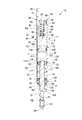
- FIG. 1 shows a smoke exhaust window 1.
- the smoke exhaust window 1 is installed at the top of the wall of the room of the building.
- the smoke exhaust window 1 has a fixed frame 4 which is a member on the building side formed with a window opening 3 communicating inside and outside of the building inside and fixed to the building, and a window 5 for opening and closing the window opening 3 of the fixed frame 4 Have.
- the window 5 is composed of a window glass 6 and a movable frame 7 attached to the window glass 6 so as to surround the entire circumference thereof and holding the window glass 6.
- the lower edge of the movable frame 7 is pivotably connected to the lower edge of the fixed frame 4 via a hinge (not shown).
- the window 5 closes the window opening 3 in a posture along the vertical, and opens the window opening 3 by swinging toward the outside of the building.
- the gas spring 10 of the first embodiment is attached between the fixed frame 4 on the building side and the movable frame 7 on the window 5 side.
- the gas spring 10 biases the window 5 in the opening direction and controls the opening speed.
- a lock mechanism (not shown) for locking the movable frame 7 of the window 5 in a state of closing the window opening 3 to the fixed frame 4 is provided between the fixed frame 4 and the movable frame 7.
- the gas spring 10 causes the window 5 to open by its biasing force.
- the window 5 is stopped at a predetermined angular position with respect to the fixed frame 4 by a stopper mechanism (not shown) when the opening operation is performed.
- the gas spring 10 is provided so as to close the bottomed cylindrical cylinder 11 whose one end is an opening 12 and the opening 12 of the cylinder 11.
- An opening closing member 13 a piston 16 slidably provided in the cylinder 11, and one end side thereof is connected to the piston 16, and the other end side extends outward from the opening 12 of the cylinder 11 via the opening closing member 13.
- a rod-like rod 17 and a free piston 18 slidably provided on the opposite side of the opening 12 relative to the piston 16 in the cylinder 11 are provided.
- a chamber 21 between the piston 16 and the opening closing member 13 a chamber 22 between the piston 16 and the free piston 18, and a piston 16 of the free piston 18 are provided by the piston 16 and the free piston 18.
- a pressurized gas G such as compressed air or compressed nitrogen gas is enclosed in a chamber 23, and an oil L as a working fluid is enclosed in a chamber 21 and a chamber 22.
- the opening closing member 13 is composed of a rod guide 30 and a sealing member 31.
- the rod guide 30 guides the movement of the rod 17 at the outer end position on the opening 12 side in the cylinder 11 to suppress the deflection.
- the seal member 31 seals between the rod 17 and the cylinder 11 at a position inside the rod guide 30 on the opening 12 side in the cylinder 11. The seal member 31 is maintained in contact with the rod guide 30 by the pressure in the chamber 21 of the cylinder 11.
- a rod bracket 33 for attaching the rod 17 to an object to be mounted is fixed by welding to an end of the rod 17 on the projecting side from the cylinder 11.
- a cylinder bracket 34 (bracket) for attaching the cylinder 11 to a mounting object is provided.
- the gas spring 10 is disposed such that the cylinder 11 is on the upper side and the rod 17 is on the lower side, and the rod bracket 33 of the rod 17 is rotatably connected to the fixed frame 4.
- a cylinder bracket 34 is rotatably connected to a movable frame 7 as a mounting object of the window 5.
- the cylinder 11 is disposed at the upper side in a so-called inverted state in which the rod 17 is at the lower side.
- the gas spring 10 extends substantially in the vertical direction with the window 5 closing the window opening 3 and in a contracted state in which the rod 17 is inserted most into the cylinder 11, and when the window 5 opens the window opening 3
- the rod 17 is in an extended state in which the amount of protrusion from the cylinder 11 is enlarged.
- the cylinder 11 includes a cylindrical body member 41 having an opening 12 at one end, and a closing member 42 closing the other end of the body 41. Therefore, in the cylinder 11, the rod 17 extends from the opening 12 at one end in the axial direction, and the other end in the axial direction is formed by the closing member 42.
- the closing member 42 closes the other end of the cylinder 11.
- the body member 41 is made of a metal material mainly made of iron or the like.
- the body member 41 has a cylindrical portion 51, an annular small diameter portion 52 and an annular step portion 53.
- the annular small diameter portion 52 and the annular step portion 53 are both recessed radially inward from the outer peripheral surface of the cylindrical portion 51 and project radially inward from the inner peripheral surface of the cylindrical portion 51. It is formed to be.
- the annular small diameter portion 52 is formed at an intermediate position opposite to the closing member 42 in the axial direction of the cylindrical portion 51.
- the annular step portion 53 is formed at the position of the opening 12 which is an end opposite to the closing member 42 in the axial direction of the cylindrical portion 51.
- the annular small diameter portion 52 and the annular step portion 53 are formed by caulking a material made of a cylindrical body of the body member 41. The portion of this material which is not crimped constitutes the cylindrical portion 51.
- the annular small diameter portion 52 is closer to the opening 12 than the piston 16 and restricts the piston 16 from passing through and coming into contact with the seal member 31.
- the rod 17 connected to the piston 16 can not extend further from the cylinder 11, that is, the gas spring 10 is in the maximum length state.
- the annular step portion 53 holds the rod guide 30 at an end position on the opening 12 side in the cylinder 11 so that the rod guide 30 does not come off the cylinder 11.
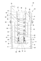
- the closing member 42 has a closing member main body 64 which is an integral molding.
- the closing member main body 64 has a cylindrical base portion 61, and a cylindrical projecting portion 62 extending to one side in the axial direction from the radial center position of the base portion 61 and having a smaller outer diameter than the base portion 61.
- the cylindrical main body 63 has a stepped cylindrical shape, and the cylinder bracket 34 described above extends from the outer peripheral side of the base 61 to the opposite side of the axially projecting portion 62.
- the closing member main body 64 is integrally formed.
- the cylinder bracket 34 is provided on the closing member 42 and integrally formed on the closing member 42.
- the closing member main body 64 is made of a metal material mainly made of iron or the like similar to the body member 41.
- the closing member main body 64 is formed, for example, by cutting out from one block-shaped material.
- the outer diameter of the base portion 61 is equal to the outer diameter of the cylindrical portion 51 of the trunk member 41.
- the closing member main body 64 is in contact with the trunk member 41 at the base portion 61 in a state in which the projecting portion 62 is disposed in the trunk member 41.
- the outer peripheral side of the contact position of the base portion 61 and the cylindrical portion 51 of the body member 41 is welded. Thereby, the closing member main body 64 is sealed and fixed to the trunk member 41 all around.
- An annular weld bead 65 is formed on the outer peripheral side of the boundary position between the base portion 61 and the cylindrical portion 51.
- a stepped portion smaller in diameter than the cylindrical portion 51 is formed by curling at the end on the joining side of the body member 41 to the closing member main body 64, and the weld bead 65 is provided in the stepped portion.
- the protrusion to the outside of the cylindrical portion 51 may be suppressed.
- a through hole 67 axially penetrating is formed in the base portion 61 at a position between the trunk member 41 and the projecting portion 62 in the radial direction.
- the closure member 42 has a plug 68 for sealing the through hole 67 of the closure member body 64.
- the plug 68 is made of a metal material mainly composed of iron or aluminum. The plug 68 is pressed into the through hole 67 to seal the through hole 67 and is fixed to the closing member main body 64.
- a female screw 71 On the inner peripheral portion of the stepped cylindrical main portion 63, from the side of the cylinder bracket 34 in the axial direction, a female screw 71, a main inner peripheral portion 72 including an inner peripheral surface consisting of a cylindrical surface, and an inner peripheral surface consisting of a cylindrical surface A valve seat 73 including a middle inner peripheral portion 74 including an inner peripheral surface formed of a cylindrical surface, and an end inner peripheral portion 75 including an inner peripheral surface formed of a cylindrical surface are formed.
- the valve seat 73 annularly protrudes radially inward of the main inner circumferential portion 72 and the middle inner circumferential portion 74 on both axial sides thereof.
- the main inner circumferential portion 72 and the end inner circumferential portion 75 have substantially the same inner diameter.
- the inner diameter of the middle inner circumferential portion 74 is smaller than the inner diameter of the end inner circumferential portion 75.
- the cylinder bracket 34 is plate-shaped. As shown in FIG. 2, the cylinder bracket 34 is formed with a mounting hole 77 penetrating in the thickness direction. The mounting hole 77 penetrates the cylinder bracket 34 along the radial direction of the main portion 63. In other words, the mounting hole 77 is formed in the cylinder bracket 34 along the direction orthogonal to the axis of the cylinder 11.
- the closing member 42 includes a pair of annular packings 81 and 82 fitted to the middle inner circumferential portion 74, grease 83 held between the packings 81 and 82, and an end An annular holding member 84 fitted to the circumferential portion 75, a valve body 85 inserted through the pair of packings 81 and 82 and the holding member 84, and a spring 86 (biased in the main inner circumferential portion 72) Means) and a cap 87 screwed to the female screw 71.
- the valve body 85 is made of a metal material mainly composed of iron or aluminum.
- the valve body 85 has a shaft portion 91 and an annular flange portion 92 protruding radially outward from one axial end of the shaft portion 91.
- the flange portion 92 is disposed radially inward of the main inner circumferential portion 72 with a gap.
- the shaft portion 91 is inserted to the inside of the valve seat 73 with a gap in the radial direction.
- the shaft portion 91 is fitted to the inside of the pair of packings 81 and 82 with an interference, and is inserted to the inside of the holding member 84 with a clearance in the radial direction.
- the outer diameter of the flange portion 92 of the valve body 85 is larger than the inner diameter of the valve seat 73, and is seated on the valve seat 73.
- the grease 83 is filled between the pair of packings 81 and 82, the middle inner circumferential portion 74 and the shaft portion 91. This is to prevent the deterioration of the pair of packings 81 and 82 by the grease 83.
- the pair of packings 81 and 82 are made of an elastic rubber material.
- the pair of packings 81 and 82 seal the gap between the shaft portion 91 and the middle inner circumferential portion 74 with the grease 83. By forming a seal, for example, heat from the outside softens the grease 83 and prevents it from flowing out of the middle inner circumferential portion 74.
- the holding member 84 is fixed to the closing member main body 64 by press-fitting and caulking the end inner circumferential portion 75. The holding member 84 regulates the removal of the pair of packings 81 and 82 from the closing member main body 64.
- the spring 86 is made of a metal material mainly composed of iron. One end of the spring 86 abuts against the flange portion 92 of the valve body 85 from the opposite side to the valve seat 73, and the other end abuts against the valve body 85 side of the cap 87 screwed with the female screw 71. Thus, the spring 86 biases the valve body 85 so that the flange portion 92 is seated on the valve seat 73.
- the cap 87 is made of a metal material or resin material mainly composed of iron or aluminum.
- the cap 87 has a cylindrical portion 96 having a through hole 95 axially penetrating at the center in the radial direction, and a hexagonal tool engaging portion 97 projecting radially outward from one end of the cylindrical portion 96 in the axial direction. And.
- An external thread 98 is formed on the outer peripheral portion of the cylindrical portion 96. The rotational force is input by the screwing tool engaged with the tool engaging portion 97, and the cap 87 is screwed with the female screw 71 at the male screw 98 and attached to the closing member main body 64. At this time, the tool engagement portion 97 abuts on the base portion 61.
- the closing member 42 includes the inside of the through hole 95 of the cap 87, the inside of the main inner circumferential portion 72 of the closing member main body 64, the inside of the valve seat 73 of the closing member main body 64, a pair of packings 81, 82 and grease 83.
- the inner side of each and the inner side of the holding member 84 constitute a communication passage 101 capable of communicating the chamber 23 in the cylinder 11 with the outside.
- the communication passage 101 is provided in the closing member 42 so that the chamber 23 in the cylinder 11 can communicate with the outside.
- the valve seat 73, the pair of packings 81, 82 and the grease 83 are provided in the communication passage 101.
- the valve body 85 is movably provided in the communication passage 101. The valve body 85 closes the communication path 101 with the pair of packings 81 and 82 and the grease 83 therebetween by fitting the pair of packings 81 and 82 with interference.
- the spring 86 biases the valve body 85 movably provided in the communication passage 101 from the outside of the cylinder 11 toward the inside of the cylinder 11.
- the flange portion 92 of the valve body 85 is seated on the valve seat 73 by the biasing force.
- the contact portion between the shaft portion 91 of the valve body 85 and the pair of packings 81 and 82 and the grease 83 is the inside of the chamber 23, the through hole 95 of the cap 87 and the main inner circumferential portion 72 of the closing member main body 64.
- the atmospheric pressure chamber 102 of the atmospheric pressure to block their communication. That is, the contact portion between the shaft portion 91 of the valve body 85 and the pair of packings 81 and 82 and the grease 83 restricts the leak of the gas G in the chamber 23 to the atmosphere chamber 102 side.
- the pressurized gas G is introduced into the chamber 23 from the through hole 67 before being sealed by the plug 68 of the base portion 61 of the closing member 42. Thereafter, the through hole 67 is sealed by the plug 68.
- the pressure of the gas G enclosed in the chamber 23 is applied to the valve body 85 in the direction from the chamber 23 to the atmosphere chamber 102, that is, from the inside of the cylinder 11 to the outside. If the ambient temperature around the gas spring 10 is less than a predetermined value, the temperature of the gas G is also less than this predetermined value, and the pressure of the gas G is less than the predetermined pressure value.
- the flange portion 92 is in a state of being seated on the valve seat 73 by the biasing force. Thereby, the state where the communication passage 101 is closed by the shaft portion 91 and the pair of packings 81 and 82 and the grease 83 is maintained.
- valve body 85 when the ambient temperature around the gas spring 10 becomes equal to or higher than a predetermined value, the temperature of the gas G also exceeds this predetermined value, and the pressure of the gas G becomes equal to or higher than the predetermined pressure value.
- the pressure of G moves the flange portion 92 away from the valve seat 73 against the biasing force of the spring 86 to move the communication passage 101 by the shaft portion 91 and the pair of packings 81 and 82 and grease 83.
- the closed state is released, and the communication passage 101 is opened.
- valve mechanism 105 having the valve seat 73, the valve body 85, the spring 86, the pair of packings 81 and 82, and the grease 83 closes the communication passage 101 and the ambient temperature becomes a predetermined value or more.
- the communication passage 101 is opened.
- the valve mechanism 105 is provided on the closing member 42 and is opened by the internal pressure of the cylinder 11.
- the valve opening pressure of the valve mechanism 105 is set so as to move the valve body 85 at least early before the oil L in the gas spring 10 reaches the boiling point to open the communication passage 101.
- the piston 16 is an annular piston main body 111 sliding in the cylindrical portion 51 of the body member 41 of the cylinder 11, and is held by the piston main body 111. And a piston seal 112 for sealing the gap.
- the piston main body 111 is made of a metal material mainly made of iron or the like.
- the piston seal 112 is made of an elastic rubber material.
- the piston body 111 is formed with a through hole 115 penetrating in the axial direction at the center in the radial direction.
- the through hole 115 mainly includes the small diameter hole 116, and the side of the opening closing member 13 in the axial direction of the small diameter hole 116 is a large diameter hole 117 having a larger diameter than the small diameter hole 116.
- the piston main body 111 is formed with an annular seal holding groove 121 which is recessed inward in the radial direction from the outer peripheral surface at the axial center of the outer peripheral portion.
- a plurality of channel holes 122 penetrating in the axial direction are formed at equal intervals in the circumferential direction on the radially inner side of the seal holding groove 121 and the radial outer side of the through hole 115 of the piston body 111 .
- a piston seal 112 is attached to the seal holding groove 121 to constitute a piston 16.
- the rod 17 is made of a metal material mainly composed of iron.
- the rod 17 has a main shaft 125 of a fixed diameter, an intermediate shaft 126 having a diameter smaller than that of the main shaft 125 formed on one end side of the main shaft 125 in the axial direction, and a main shaft 125 of the intermediate shaft 126 in the axial direction.
- a fitting shaft formed on the opposite side of the fitting shaft 127 having a diameter smaller than that of the middle shaft 126 and the middle shaft 126 in the axial direction of the fitting shaft 127.
- an engaging portion 128 having a diameter larger than 127.
- the engagement portion 128 is formed by caulking.
- the engagement portion 128 of the rod 17 is in contact with the stepped portion of the boundary between the large diameter hole portion 117 and the small diameter hole portion 116 of the piston main body 111 at the end of the intermediate shaft portion 126 on the fitting shaft portion 127 side.
- the fitting shaft 127 before being formed is fitted in the small diameter hole 116.
- the distal end of the fitting shaft 127 is crimped to form the engaging portion 128.
- the piston 16 is connected to the rod 17 in a state in which the axial movement is restricted.
- the rod 17 projects from the cylinder 11 to the outside through the seal member 31 and the rod guide 30 at the main shaft 125.
- the free piston 18 is held by the disk-like free piston main body 131 sliding in the cylindrical portion 51 of the body member 41 of the cylinder 11 and the free piston main body 131 to form a gap between the free piston main body 131 and the body member 41. And a free piston seal 132 for sealing.
- the free piston main body 131 is made of a metal material mainly made of iron or aluminum.
- the free piston seal 132 is made of an elastic rubber material.
- an annular seal holding groove 133 which is recessed radially inward from the outer peripheral surface is formed at an intermediate position in the axial direction of the outer peripheral portion.
- the free piston seal 132 is attached to the seal holding groove 133, and the free piston 18 is configured.
- the free piston 18 is disposed between the piston 16 and the closing member 42 in the cylindrical portion 51 of the cylinder 11.
- the free piston 18 moves within the cylindrical portion 51 so as to equalize the chambers 22 and 23 on both sides thereof.
- a pressure difference occurs due to the movement of the piston 16, the chambers 21 and 22 communicate with each other through the flow passage hole 122 of the piston 16, and therefore the pressure becomes equal when the piston 16 stops.
- the chamber 23 is filled with the pressurized gas G at the time of manufacture, when the chambers 21, 22 and 23 are at the same pressure, the chambers 21 to 23 have a pressure higher than atmospheric pressure.
- the rod guide 30 is made of, for example, a material in which about 50% of glass fiber is mixed with a synthetic resin such as polyamide.
- the rod guide 30 is formed with an insertion hole 141 axially penetrating at the center in the radial direction.
- a large diameter portion 142, an intermediate diameter portion 143 smaller in diameter than the large diameter portion 142, and a small diameter portion 144 smaller in diameter than the intermediate diameter portion 143 are provided in the axial direction. It is formed in order.
- the rod guide 30 is fitted to the body member 41 of the cylinder 11 before caulking at the large diameter portion 142 in a state where the rod 17 is inserted into the insertion hole 141.
- the seal member 31 is made of an elastic rubber material such as nitrile rubber.
- the seal member 31 has an annular shape.
- the seal member 31 is in contact with the end face of the rod guide 30 on the side of the large diameter portion 142 in the axial direction. In this state, the outer peripheral side is fitted to the cylindrical portion 51 of the cylinder 11 with an interference, and the main shaft portion 125 of the rod 17 is inserted to the inner peripheral side with the interference.
- the seal member 31 is always pressed against the rod guide 30 by the pressure of the fluid L in the chamber 21 of the cylinder 11.
- the rod bracket 33 has a bracket main body 151 made of a metal material mainly made of iron or aluminum or the like, and a collar 152 made of a synthetic resin material.
- the bracket main body 151 is formed by bending a plate material.
- the bracket main body 151 is a plate-like portion 155 fixed to the end of the main shaft portion 125 of the rod 17 and a plate-like portion extending in the direction away from the rod 17 along the axial direction of the rod 17 from the plate-like portion 155 And 156.
- the plate-like portion 156 overlaps the extension of the central axis of the rod 17 on the side opposite to the plate-like portion 155.
- a mounting hole 157 penetrating in the thickness direction is formed in this portion.
- the mounting hole 157 is formed in the rod bracket 33 along the axis orthogonal direction of the cylinder 11.
- the collar 152 is fitted in the mounting hole 157 and attached to the bracket main body 151.
- the packing 81, 82, grease 83, holding member 84, valve body 85, spring 86 and cap 87 other than the plug 68 are assembled to the closing member main body 64 to be in the state of a subassembly. In the state of this subassembly, it is fixed to the body member 41 by welding.
- the gas spring 10 is assembled until the through hole 67 of the closing member 42 is closed by the plug 68. Thereafter, for example, by disposing the gas spring 10 in the atmosphere of the pressurized gas G, the pressurized gas G is introduced into the chamber 23 through the through hole 67. Thereafter, when the plug 68 is pressed into and fixed to the through hole 67 in the atmosphere of the pressurized gas G, the through hole 67 is closed by the plug 68.
- the gas spring 10 in which the chamber 23 is filled with the pressurized gas G is manufactured.
- Such a gas spring 10 is attached to the fixed frame 4 on the building side of the smoke exhaust window 1 at the rod bracket 33 with the rod 17 at the lower side and the cylinder 11 at the upper side, as described above.
- the bracket 34 is attached to the movable frame 7 on the window 5 side. In this state, the oil L comes into contact with the rod 17, the seal member 31, the piston seal 112, the free piston seal 132, and the like.
- the gas spring 10 makes the protrusion amount of the rod 17 from the cylinder 11 the smallest. Is located closest to the closing member 42 of the cylinder 11. At this time, the pressure of the oil L in the chambers 21 and 22 and the pressure of the gas G in the chamber 23 are equal to each other and are higher than the atmospheric pressure. Due to the pressure of the piston 16 and the pressure receiving area difference of the piston 16, an urging force in the direction of causing the rod 17 to project from the cylinder 11 is generated in the piston 16.
- the gas spring 10 extends so as to increase the amount of protrusion of the rod 17 from the cylinder 11 and presses the movable frame 7 Then, the window 5 is opened. At this time, the fluid L flows from the chamber 21 to the chamber 22 through the passage hole 122 which becomes the orifice of the piston 16 due to the movement of the piston 16. As a result, a damping force is generated to reduce the opening speed of the movable frame 7.
- the gas spring 10 reduces the amount of protrusion of the rod 17 from the cylinder 11 So as to shorten.
- the fluid L flows from the chamber 22 to the chamber 21 through the passage hole 122 by the movement of the piston 16.
- valve body 85 of the valve mechanism 105 seats the flange portion 92 on the valve seat 73 by the biasing force of the spring 86.
- the communication passage 101 is closed by the shaft portion 91, the pair of packings 81 and 82, and the grease 83.
- the internal pressure rises when a fire occurs in the building and the building is exposed to a high temperature atmosphere.
- the rising internal pressure causes the valve body 85 of the valve mechanism 105 to release the flange portion 92 from the valve seat 73 against the biasing force of the spring 86 at least early before the oil L reaches the boiling point.
- the closed state of the communication passage 101 by the shaft portion 91 and the pair of packings 81 and 82 and the grease 83 is released, the communication passage 101 is opened, and the gas G in the chamber 23 of the cylinder 11 is Leak to the outside.
- Patent Document 1 described above discloses a gas spring for a window of a smoke exhaust window capable of suppressing an increase in internal pressure in a state of being exposed to a high temperature atmosphere.
- Patent Document 1 discloses a structure in which a discharge member for discharging gas from the inside of the cylinder is provided on the side of the cylinder, and the gas is discharged from the inside of the cylinder to a rod guide that is on the lower side in a mounted state to a smoke exhaust window.
- the gas spring 10 forms the other end of the cylinder 11 from which the rod 17 extends from one end, and a cylinder bracket 34 for attaching the cylinder 11 to a mounting object.
- the member 42 is provided with a communication passage 101 capable of communicating the inside of the cylinder 11 with the outside, and a valve mechanism 105 for closing the communication passage 101 and opening the communication passage 101 when the ambient temperature reaches a predetermined value or more.
- the valve mechanism 105 for suppressing the rise of the internal pressure is provided in the closing member 42 which is the upper side in the attached state to the smoke exhaust window 1, it is possible to suppress the leakage of the hydraulic fluid. .
- a valve mechanism 105 which is opened by the internal pressure of the cylinder 11 is used as an open mechanism which opens the communication passage 101 when the ambient temperature reaches a predetermined value or more.
- the communication passage 101 can be opened satisfactorily.
- the temperature may increase during manufacture, and for example, welding can be employed for attaching the closing member 42 to the body member 41 as described above, so that manufacture is easy. It becomes.
- the valve mechanism 105 has a valve seat 73 provided in the communication passage 101, a valve body 85 which is seated on the valve seat 73, and a spring 86 which biases the valve body 85 from the outside toward the inside of the cylinder 11. doing. This enables quantitative internal pressure management.
- the gas spring 10 exhibits the above effect.
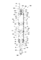
- the cylinder 11 ⁇ / b> A is partially different from the cylinder 11 of the first embodiment.
- the closing member 42A is partially different from the closing member 42 of the first embodiment.
- the closing member 42A of the second embodiment has a cylindrical main body 63A and a cylinder bracket 34 similar to that of the first embodiment extending axially from the outer peripheral side of the main body 63A.
- a closure member main body 64A which is an integral molding.
- annular engagement groove 201 recessed radially inward from the outer peripheral surface is formed in an intermediate portion opposite to the cylinder bracket 34 in the axial direction.
- the cylinder bracket 34 of the engagement groove 201 is formed.
- An annular seal groove 202 which is recessed radially inward from the outer peripheral surface is formed in the fitting portion 204 on the opposite side.
- the closing member 42A has a seal ring 203 fitted in the seal groove 202.
- the closing member main body 64A is made of a metal material mainly composed of iron or aluminum.
- the seal ring 203 is made of an elastic rubber material.
- the cylinder 11A is also different from the body 41 of the first embodiment in part.
- a crimped portion 205 crimped and bent radially inward of the cylindrical portion 51 is formed at an end of the body member 41A on the joining side to the closing member main body 64A.
- the fitting part 204 of the closing member main body 64A with the seal ring 203 attached is fitted to the cylindrical part 51 from the opening side of the body member 41A.
- the crimped portion 205 is formed and engaged with the engagement groove 201.
- the closing member main body 64A is fixed to the trunk member 41A.
- the seal ring 203 provided in the fitting portion 204 closes the gap between the closing member main body 64A and the body member 41A.
- An external screw may be formed on the outer peripheral side of the fitting portion 204 of the closing member main body 64A, and a female screw may be formed on the inner peripheral side of the body member 41A, and these may be screwed together. In this case, after screwing, it is preferable to crimp the rotation stopper.
- the cylinder 11A includes the closing member 42A and the body member 41A to which the closing member 42A is fixed.
- the closing member 42A is fixed to the body member 41A by a caulking portion 205 formed by caulking the body member 41A. That is, the closing member main body 64A is fixed to the body member 41A without using welding.
- the closing member main body 64A includes a female screw 211, a large diameter inner circumferential portion 212 including an inner circumferential surface consisting of a cylindrical surface, and a cylindrical surface on an inner circumferential portion of a cylindrical main portion 63A in order from the axial cylinder bracket 34 side.
- a small diameter inner circumferential portion 213 smaller in diameter than the large diameter inner circumferential portion 212 including the inner circumferential surface is formed.
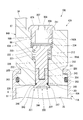
- the closing member 42A is provided with the valve body 221 disposed in the large diameter inner circumferential portion 212 and the small diameter inner circumferential portion 213, and iron in a state where the valve body 221 is inserted inside the large diameter inner circumferential portion 212. And a cap 87A which is partially different from the cap 87 of the first embodiment which is screwed to the female screw 211.
- the cap 87A is made of a metal material or resin material mainly composed of iron or aluminum.
- the cap 87A is provided with a through hole 95A at the center in the radial direction of the cylindrical portion 96A.
- the through hole 95A has a small diameter hole 207 at the end on the tool engaging portion 97 side in the axial direction and a large diameter hole 208 having a diameter larger than that of the small diameter hole 207 other than the small diameter hole 207.
- the cap 87A is also attached to the closing member main body 64A by the rotational force being input by the screwing tool engaged with the tool engaging portion 97 and the male screw 98 being screwed with the female screw 211.
- the valve body 221 includes a support member 226, a plug 227, and a seal ring 228.
- the support member 226 is made of a metal material mainly composed of iron or aluminum.
- the support member 226 protrudes radially outward from the main shaft portion 231, a screw shaft portion 232 protruding in the axial direction from one axial end of the main shaft portion 231, and the other axial end of the main shaft portion 231.
- an annular flange portion 233 is formed at an end of the main shaft portion 231 on the side of the flange portion 233 in the axial direction.
- the main shaft portion 231 is inserted in the small diameter inner circumferential portion 213 with a gap in the radial direction, and the flange portion 233 is disposed in the large diameter inner circumferential portion 212 in the radial direction with a gap.
- the plug 227 has a main shaft portion 241 and an annular flange portion 242 projecting radially outward from one axial end of the main shaft portion 241.
- a screw hole 243 is formed in the main shaft portion 241 opposite to the flange portion 242 in the axial direction, and a hexagonal tool engagement hole 244 is formed in an end portion on the flange portion 242 side in the axial direction.
- an annular seal groove 245 which is recessed radially inward from the outer peripheral surface is formed in the main shaft portion 241, in the vicinity of the flange portion 242 in the axial direction.
- the seal ring 228 is made of an elastic rubber material. The seal ring 228 fits in the seal groove 245.
- the flange portion 242 has a tapered surface 246 in which the surface on the seal groove 245 side in the axial direction has a smaller diameter toward the seal groove 245.
- the flange portion 242 is formed with a notch 247 which is recessed radially inward from the outer peripheral surface.
- the main shaft portion 241 of the plug 227 is inserted into the small diameter inner circumferential portion 213 with a gap in the radial direction, and the flange portion 242 is disposed outside the small diameter inner circumferential portion 213.
- the support member 226 is inserted inside the large diameter inner peripheral portion 212 in a state where the spring 222 is disposed inside the large diameter inner peripheral portion 212.
- the main shaft portion 231 is inserted into the spring 222 and the small diameter inner circumferential portion 213.
- the main shaft portion 241 of the plug 227 to which the seal ring 228 is attached is inserted into the small diameter inner peripheral portion 213 from the opposite side to the large diameter inner peripheral portion 212.
- the portion 232 is screwed to fasten the support member 226 and the plug 227.
- the rotational force is input to the support member 226 by the screwing tool engaged with the tool engagement hole 234, and the plug 227 is rotated by the screwing tool engaged with the tool engagement hole 244.
- Force is input.
- the outer peripheral surfaces of the main shaft portions 231 and 241 have the same diameter, and when the support member 226 and the plug 227 are fastened, the outer peripheral surfaces are coaxially arranged.
- the spring 222 assembled together with the valve body 221 to the closing member main body 64A abuts against the flange portion 233 of the support member 226 of the valve body 221, and the other end is the large diameter inside of the small diameter inner circumferential portion 213 of the closing member main body 64A. It abuts on the end on the circumferential portion 212 side. Thereby, the spring 222 presses the flange portion 233 in the direction away from the small diameter inner circumferential portion 213, and the tapered surface 246 of the flange portion 242 of the plug 227 is the inner diameter of the large diameter inner circumferential portion 213 of the closing member main body 64A. The end opposite to the portion 212 is abutted.
- the seal ring 228 fits inside the small diameter inner circumferential portion 213 to close the gap between the closing member main body 64A and the plug 227.
- An end opposite to the large diameter inner circumferential portion 212 of the small diameter inner circumferential portion 213 is a valve seat 251 on which the valve body 221 is seated and separated.
- the spring 222 biases the flange portion 242 of the plug 227 of the valve body 221 to be seated on the valve seat 251.
- the rotational force is input by the screwing tool engaged with the tool engaging portion 97 of the cap 87A. Is screwed onto the female screw 211 of the closing member main body 64A and attached to the closing member main body 64A.
- the cap 87A covers the valve body 221 in a state in which the flange portion 242 is seated on the valve seat 251, and is separated from the valve body 221.
- the outer diameter of the flange portion 233 of the support member 226 is larger than the inner diameter of the large diameter hole portion 208 of the cylindrical portion 96A of the cap 87A.
- the inside of the through hole 95A of the cap 87A, the inside of the large diameter inner peripheral portion 212 of the closing member main body 64A, and the inner side of the small diameter inner peripheral portion 213 can communicate the chamber 23 in the cylinder 11A with the outside.
- the communication passage 101A is configured.
- the communication passage 101A is provided in the closing member 42A and can communicate the inside of the cylinder 11A with the outside.
- the valve body 221 is movably provided in the communication passage 101A, and by fitting the small diameter inner peripheral portion 213 in the seal ring 228 mounted on the main shaft portion 241 of the plug 227, the main shaft portion 241 and the main shaft portion 241 The seal ring 228 closes the communication passage 101A.
- the spring 222 biases the valve body 221 provided in the communication passage 101A from the inside of the cylinder 11 to the outside of the cylinder 11.
- the flange portion 242 of the valve body 221 is seated on the valve seat 251 by the biasing force.
- the contact portion between the seal ring 228 of the valve body 221 and the small diameter inner circumferential portion 213 of the closing member main body 64A is the chamber 23, the inside of the through hole 95A of the cap 87A and the large diameter inner circumferential portion of the closing member main body 64
- An atmosphere chamber 102A at atmospheric pressure such as in 212 is partitioned to block the communication between them. That is, the contact portion between the seal ring 228 of the valve body 221 and the small diameter inner peripheral portion 213 of the closing member main body 64A regulates the leakage of the gas G in the chamber 23 to the atmosphere chamber 102A side.
- valve body 221 When the valve body 221 is moved from this state to a position where the seal ring 228 comes out of the small diameter inner peripheral portion 213 of the closing member main body 64A against the urging force of the spring 222, the communication passage 101A is opened to 23 and the atmosphere chamber 102A are communicated.
- a valve body 221 having a valve seat 251, a support member 226, a plug 227 and a seal ring 228 and seated on the valve seat 251, and urging the valve body 221 from the inside of the cylinder 11 to the outside of the cylinder 11.
- the spring 222 which forms the opening and closing mechanism, constitutes an opening mechanism 255 for opening and closing the communication passage 101A.
- the plug 227 shrinks and deforms due to heat. During normal operation of the gas spring 10, that is, when the gas spring 10 is within a predetermined normal temperature range, the plug 227 does not deform and closes the communication passage 101A. On the other hand, when the temperature of the plug 227 rises to a predetermined temperature equal to or lower than the boiling point of the hydraulic fluid L which is the hydraulic fluid, it shrinks and deforms to position the notch 247 radially inward of the small diameter inner circumferential portion 213 The groove 245 is contracted to separate the seal ring 228 from the small diameter inner peripheral portion 213 of the closing member main body 64A. Thus, the plug 227 opens the communication passage 101A and leaks the gas G in the chamber 23 of the cylinder 11 to the outside through the communication passage 101A.
- the plug 227 is thus formed of a material that changes with temperature.
- the plug 227 is formed of a material having a melting point lower than that of the material forming the cylinder 11 and the rod guide 30, and having a melting point equal to or lower than the boiling point of the hydraulic fluid L which is a hydraulic fluid.
- the plug 227 is made by mixing glass fiber with synthetic resin, with a body member 41A, a closing member main body 64A, a cap 87A, a support member 226 and a spring 222 all made of metal material mainly composed of iron or aluminum etc. It is made of tin or tin alloy having a low melting point with respect to the rod guide 30 made of a material, and shrinks and melts at about 200 ° C. to melt and open the communication path 101A.
- the temperature compensation range at the time of use of the gas spring 10A used for the smoke exhaust window 1 is, for example, ⁇ 20 ° C. to 60 ° C.
- the compensation temperature at storage is, for example, 100 ° C.
- the normal temperature range of is, for example, -20.degree. C. to 100.degree. C., and in at least this range, the plug 227 is not deformed.
- the valve body 221, the spring 222, the cap 87A and the seal ring 203 are assembled to the closing member main body 64A to be in the state of a subassembly.
- the closing member 42A is fitted at the fitting portion 204 to the body member 41A before the caulking portion 205 is formed.
- a crimped portion 205 is formed on the body member 41A by caulking so as to engage with the engagement groove 201.
- the gas spring 10A is assembled to a state before the pressurized gas G is introduced into the chamber 23. Thereafter, in a state where the gas spring 10A is disposed in the atmosphere of the pressurized gas G, for example, a rod-like pressing tool is inserted into the through hole 95A of the cap 87A.
- a rod-like pressing tool is inserted into the through hole 95A of the cap 87A.
- the valve body 221 is moved by the biasing force of the spring 222, and the seal ring 228 is fitted to the small diameter inner circumferential portion 213 to close the communication passage 101A, and the valve seat Seat at 251 and stop.
- the gas spring 10A in which the pressurized gas G is filled in the chamber 23 is manufactured.
- the gas spring 10A of the second embodiment also has the rod bracket 33 at the lower side and the cylinder 11A at the upper side, as in the first embodiment. It is attached to the fixed frame 4 and attached to the movable frame 7 on the window 5 side in the cylinder bracket 34.
- the gas spring 10A is similar to the first embodiment from the cylinder 11A of the rod 17.
- the amount of protrusion is the smallest, and the biasing force in the direction of causing the rod 17 to protrude from the cylinder 11A is generated in the piston 16 by the pressure of the oil L in the chambers 21 and 22 and the pressure receiving area difference of the piston 16.
- the gas spring 10A increases the protrusion amount of the rod 17 from the cylinder 11A as in the first embodiment.
- the movable frame 7 is pressed to open the window 5.
- valve body 221 of the release mechanism 255 causes the flange portion 242 of the plug 227 to be seated on the valve seat 251 by the biasing force of the spring 222.
- the plug 227 and the seal ring 228 keep the communication passage 101A closed.
- the plug 227 of the opening mechanism 255 is deformed and melted and flows into the chamber 23 at least early before the oil L reaches the boiling point.
- the communication passage 101A is opened to leak the gas G in the chamber 23 of the cylinder 11A to the outside through the communication passage 101A. Therefore, as in the first embodiment, it is possible to suppress an increase in internal pressure in a high temperature atmosphere.
- the gas spring 10A forms the other end of the cylinder 11A from which the rod 17 extends from one end and is provided with the cylinder bracket 34 for attaching the cylinder 11A to the object to be mounted.
- the member 42A is provided with a communication passage 101A capable of communicating the inside of the cylinder 11A with the outside, and an opening mechanism 255 for closing the communication passage 101A and opening the communication passage 101A when the ambient temperature becomes a predetermined value or more. There is.
- the opening mechanism 255 for suppressing the rise in the internal pressure of the gas G enclosed in the chamber 23 is provided in the closing member 42A, which is the upper side in the attached state to the smoke exhaust window 1, It becomes possible to control leakage.
- the opening mechanism 255 for opening the communication passage 101A when the ambient temperature reaches a predetermined value or more has the plug 227 deformed by heat the communication passage 101A can be favorably opened with a simple structure.
- the closing member 42A is fixed to the body member 41A by the caulking portion 205 formed by caulking the body member 41A, the cylinder 11A can suppress the occurrence of contamination due to welding.
- the gas G can be introduced at the time of manufacture by using the communication passage 101A for discharging the gas G in order to suppress the rise of the internal pressure in the high temperature atmosphere, the structure can be simplified.
- the plug 227 is formed with the notch 247 which is recessed radially inward from the outer peripheral surface in the flange 242 which abuts on the valve seat 251, the communication passage 101A can be opened at an early stage of thermal contraction.
- the cap 87A covers the front in the biasing direction of the spring 222 with respect to the valve body 221 in a state in which the flange portion 242 is seated on the valve seat 251. Therefore, even if the plug 227 is contracted to a size that allows the plug 227 to pass through the small diameter inner circumferential portion 213 and the valve body 221 moves outward by the biasing force of the spring 222, the support member 226 abuts on the cap 87A. Stop and prevent the valve body 221 from jumping out of the closing member main body 64A.
- the gas spring 10A exhibits the above effect.
- the gas springs 10 and 10A of the first and second embodiments are of the type having the free piston 18 in the cylinders 11 and 11A, but the present invention is also applied to a gas spring of the type having no free piston 18 It is possible.
- the gas spring includes a rod, a cylinder from which the rod extends from one end, and a cylinder into which gas and hydraulic fluid are enclosed, and the cylinder
- a closing member formed integrally with a bracket for closing the end and attaching the cylinder to the attachment, a communication passage provided on the closing member and capable of communicating the inside and the outside of the cylinder, and the communication passage
- an opening mechanism for closing the communication passage when the ambient temperature reaches a predetermined value or higher Therefore, it is possible to suppress the leakage of the hydraulic fluid.
- a second aspect of the gas spring according to the embodiment is characterized in that, in the first aspect, the opening mechanism is a valve mechanism that opens with the internal pressure of the cylinder. Therefore, the communication passage 101 can be opened satisfactorily.
- the valve mechanism in a third aspect of the gas spring according to the embodiment, in the second aspect, includes a valve seat provided in the communication passage, a valve body which is seated on the valve seat, and the valve body from the outside And biasing means for biasing the cylinder inward.
- a fourth aspect of the gas spring according to the embodiment is characterized in that, in the first aspect, the opening mechanism has a plug that is deformed by heat.
- the communication passage 101A can be favorably opened with a simple structure.
- the cylinder in a fifth aspect of the gas spring according to the embodiment, in the fourth aspect, includes the closing member and a body member to which the closing member is fixed, and the closing member is the body member Is fixed to the body member by a caulking portion formed by caulking.
- the closing member is the body member Is fixed to the body member by a caulking portion formed by caulking.
- the gas spring of any one of the first to fifth aspects is attached. Therefore, it is possible to reduce the possibility that the parts may be broken and the parts may be scattered, or the oil L as the hydraulic fluid sealed inside may be scattered.
Landscapes
- Engineering & Computer Science (AREA)
- General Engineering & Computer Science (AREA)
- Mechanical Engineering (AREA)
- Civil Engineering (AREA)
- Structural Engineering (AREA)
- Fluid-Damping Devices (AREA)
Abstract
このガススプリング(10)は、ロッド(17)と、一端からロッド(17)が延出し、内部にガス(G)および作動液(L)が封入されるシリンダ(11)と、シリンダ(11)の他端を閉塞するとともにシリンダ(11)を被取付物に取り付けるためのブラケット(34)が一体形成された閉塞部材(42)と、閉塞部材(42)に設けられ、シリンダ(11)内と外部とを連通可能な連通路(101)と、連通路(101)を閉塞し、雰囲気温度が所定値以上になった際に連通路(101)を開放する開放機構(105)と、を有する。
Description
本発明は、ガススプリングおよびこれを用いた排煙窓に関する。
本願は、2017年7月27日に、日本に出願された特願2017-145698号に基づき優先権を主張し、その内容をここに援用する。
本願は、2017年7月27日に、日本に出願された特願2017-145698号に基づき優先権を主張し、その内容をここに援用する。
排煙窓用のガススプリングにおいて、高温雰囲気に晒されたときに、内圧の上昇を抑制する構成が知られている(例えば、特許文献1参照)。
ガススプリングにおいて、作動液の漏出を抑制することが求められている。
本発明は、作動液の漏出を抑制することが可能となるガススプリングおよびこれを用いた排煙窓を提供する。
本発明の一態様によれば、ガススプリングは、一端からロッドが延出するシリンダの他端を形成するとともに該シリンダを被取付物に取り付けるためのブラケットが設けられた閉塞部材と、前記閉塞部材に設けられ、前記シリンダ内と外部とを連通可能な連通路と、前記連通路を閉塞し、雰囲気温度が所定値以上になった際に前記連通路を開放する開放機構と、を有する。
上記したガススプリングによれば、作動液の漏出を抑制することが可能となる。
「第1実施形態」
本発明に係る第1実施形態を図1~図3に基づいて説明する。
本発明に係る第1実施形態を図1~図3に基づいて説明する。
図1は、排煙窓1を示している。排煙窓1は、建物の部屋の壁の上部に設置される。排煙窓1は、建物の内外を連通させる窓開口3が内側に形成され建物に固定される建物側の部材である固定枠4と、固定枠4の窓開口3を開閉する窓5とを有している。窓5は、窓ガラス6と、窓ガラス6にその全周を囲むように取り付けられて窓ガラス6を保持する可動枠7とから構成されている。可動枠7の下縁が固定枠4の下縁に図示略のヒンジを介して揺動可能に連結されている。窓5は、鉛直に沿う姿勢で窓開口3を閉塞し、建物の外側に向け揺動することで窓開口3を開放する。
建物側の固定枠4と窓5側の可動枠7との間に、第1実施形態のガススプリング10が取り付けられている。ガススプリング10は、窓5を開方向に付勢するとともに開速度を制御する。なお、固定枠4と可動枠7との間には、窓開口3を閉塞する状態の窓5の可動枠7を固定枠4にロックする図示略のロック機構が設けられている。このロック機構のロックが解除されると、ガススプリング10がその付勢力で窓5を開作動させることになる。窓5は開作動時には図示略のストッパ機構によって固定枠4に対して所定の角度位置で停止させられる。
第1実施形態のガススプリング10は、図2に示すように、一端側が開口部12とされた有底筒状のシリンダ11と、シリンダ11の開口部12にこれを閉鎖するように設けられた開口閉鎖部材13と、シリンダ11内に摺動可能に設けられたピストン16と、一端側がピストン16に連結され他端側が開口閉鎖部材13を介してシリンダ11の開口部12から外部に延出される棒状のロッド17と、シリンダ11内のピストン16よりも開口部12とは反対側に摺動可能に設けられたフリーピストン18と、を有している。
シリンダ11内は、ピストン16とフリーピストン18とによって、ピストン16と開口閉鎖部材13との間の室21と、ピストン16とフリーピストン18との間の室22と、フリーピストン18のピストン16とは反対側の室23と、に区画されている。シリンダ11内には、室23に圧縮空気や圧縮窒素ガス等の加圧されたガスGが封入されており、室21と室22とに作動液としての油液Lが封入されている。シリンダ11に対してピストン16が停止した状態では、室21と室22と室23とは大気圧よりも高い等圧になっている。
開口閉鎖部材13は、ロッドガイド30と、シール部材31とから構成されている。ロッドガイド30は、シリンダ11内の開口部12側の外端位置にてロッド17の移動をガイドしてその振れを抑制する。シール部材31は、シリンダ11内の開口部12側のロッドガイド30よりも内側位置にてロッド17とシリンダ11との間を密閉する。シール部材31はシリンダ11の室21内の圧力によりロッドガイド30に当接した状態に維持されている。
ロッド17のシリンダ11からの突出側の端部には、ロッド17を被取付物に取り付けるためのロッドブラケット33が溶接により固定されている。シリンダ11のロッド17が延出する一端とは反対の他端には、シリンダ11を被取付物に取り付けるためのシリンダブラケット34(ブラケット)が設けられている。
ガススプリング10は、図1に示すように、シリンダ11が上側にロッド17が下側になるように配置され、ロッド17のロッドブラケット33が固定枠4に回動可能に連結され、シリンダ11のシリンダブラケット34が窓5の被取付物としての可動枠7に回動可能に連結されている。なお、フリーピストン18を構成しない型式の排煙窓用のガススプリングでは、作動する頻度が少ないことから、シール部材31をその性能維持のため油液Lに常時接触させておく必要があるため、シリンダ11が上側にロッド17が下側になる、いわゆる倒立状態で配置する。ガススプリング10は、窓5が窓開口3を閉じた状態では、略鉛直方向に沿うとともにロッド17がシリンダ11内に最も入り込んだ縮長状態となり、窓5が窓開口3を開いた状態では、ロッド17がシリンダ11からの突出量を拡大する伸長状態となる。
シリンダ11は、一端側が開口部12を形成する円筒状の胴部材41と、胴部材41の他端側を閉塞する閉塞部材42とから構成されている。よって、シリンダ11は、軸方向の一端の開口部12からロッド17が延出し、軸方向の他端が閉塞部材42で形成されている。閉塞部材42はシリンダ11の他端を閉塞する。
胴部材41は、鉄等を主体とする金属材料から構成されている。胴部材41は、円筒部51と、円環状の環状小径部52および円環状の環状段差部53と、を有している。円環状の環状小径部52と、円環状の環状段差部53とは、いずれも、円筒部51の外周面から径方向内方に凹むとともに円筒部51の内周面から径方向内方に突出するように形成されている。環状小径部52は、円筒部51の軸方向の閉塞部材42とは反対側の中間位置に形成されている。環状段差部53は、円筒部51の軸方向の閉塞部材42とは反対側の端部である開口部12の位置に形成されている。環状小径部52および環状段差部53は、胴部材41の円筒体からなる素材に加締め加工を施すことにより形成されている。この素材の、加締め加工されない部分が円筒部51を構成する。
環状小径部52は、ピストン16よりも開口部12側にあり、ピストン16が通過してシール部材31に当接することを規制する。ピストン16が環状小径部52に当接すると、ピストン16に連結されたロッド17がそれ以上シリンダ11から延出不可な状態、つまりガススプリング10が最大長の状態となる。環状段差部53は、ロッドガイド30がシリンダ11から抜け出ないようにロッドガイド30をシリンダ11内の開口部12側の端部位置に保持している。
閉塞部材42は、一体成形品である閉塞部材本体64を有している。閉塞部材本体64は、円筒状の基体部61と、基体部61の径方向の中央位置から軸方向一側に延出する、基体部61よりも外径が小径の円筒状の突出部62とを有する段付き円筒状の主体部63と、基体部61の外周側から軸方向の突出部62とは反対側に延出する、上記したシリンダブラケット34とを有している。閉塞部材本体64は、これらが一体成形されている。よって、シリンダブラケット34は、閉塞部材42に設けられて、閉塞部材42に一体形成されている。閉塞部材本体64は、胴部材41と同様の鉄等を主体とする金属材料から構成されている。閉塞部材本体64は、例えば、一つのブロック状の素材から削り出しで形成されている。
基体部61は、外径が胴部材41の円筒部51の外径と同等である。閉塞部材本体64は、突出部62が胴部材41内に配置された状態で、基体部61において胴部材41に当接している。基体部61と胴部材41の円筒部51との当接位置の外周側が溶接される。これにより、閉塞部材本体64は、胴部材41に全周にわたって密閉されて固定されている。基体部61と円筒部51との境界位置の外周側には円環状の溶接ビード65が形成されている。なお、胴部材41の閉塞部材本体64への接合側の端部にカール加工で円筒部51よりも小径となる段差部を形成し、溶接ビード65をこの段差部内に設けて、溶接ビード65の円筒部51よりも外側への突出を抑制するようにしても良い。
図3に示すように、基体部61には、胴部材41と突出部62との径方向の間位置に、軸方向に貫通する貫通穴67が形成されている。閉塞部材42は、閉塞部材本体64のこの貫通穴67を封止するプラグ68を有している。プラグ68は、鉄あるいはアルミニウム等を主体とする金属材料から構成されている。プラグ68は、貫通穴67に圧入されて貫通穴67を封止するとともに閉塞部材本体64に固定される。
段付き円筒状の主体部63の内周部には、軸方向のシリンダブラケット34側から順に、メネジ71、円筒面からなる内周面を含む主内周部72、円筒面からなる内周面を含む弁座73、円筒面からなる内周面を含む中間内周部74、円筒面からなる内周面を含む端部内周部75が形成されている。
弁座73は、その軸方向両側の主内周部72および中間内周部74よりも径方向内方に円環状に突出している。主内周部72および端部内周部75は、内径がほぼ同等である。中間内周部74は、内径が、端部内周部75の内径よりも小径となっている。
シリンダブラケット34は、板状である。シリンダブラケット34には、図2に示すように、厚さ方向に貫通する取付穴77が形成されている。取付穴77は、主体部63の径方向に沿ってシリンダブラケット34を貫通している。言い換えれば、取付穴77は、シリンダブラケット34にシリンダ11の軸直交方向に沿って形成されている。
図3に示すように、閉塞部材42は、中間内周部74に嵌合される円環状の一対のパッキン81,82と、これらパッキン81,82の間に保持されるグリス83と、端部内周部75に嵌合される円環状の保持部材84と、一対のパッキン81,82および保持部材84に挿通される弁体85と、主内周部72内に配置されるスプリング86(付勢手段)と、メネジ71に螺合されるキャップ87と、を有している。
弁体85は、鉄あるいはアルミニウム等を主体とする金属材料から構成されている。弁体85は、軸部91と、軸部91の軸方向の一端から径方向外方に突出する円環状のフランジ部92とを有している。弁体85は、フランジ部92が主内周部72の内側に径方向に隙間をもって配置されている。軸部91が、弁座73の内側に径方向に隙間をもって挿通される。軸部91は、一対のパッキン81,82の内側に締め代をもって嵌合され、保持部材84の内側に径方向に隙間をもって挿通されている。弁体85は、フランジ部92の外径が弁座73の内径よりも大径であり、弁座73に離着座する。
グリス83は、一対のパッキン81,82と中間内周部74と軸部91との間に充填されている。これは、グリス83により、一対のパッキン81,82の劣化を防止するためである。一対のパッキン81,82は弾性ゴム材料から構成されている。一対のパッキン81,82は、グリス83とで軸部91と中間内周部74との隙間を密封する。密封をするように構成することで、例えば外部からの熱により、グリス83が軟化し、中間内周部74外に流れ出ることを抑制している。保持部材84は、端部内周部75に圧入されて加締められることで、閉塞部材本体64に固定される。保持部材84は、一対のパッキン81,82の閉塞部材本体64からの抜けを規制する。
スプリング86は、鉄を主体とする金属材料から構成されている。スプリング86は、一端が弁体85のフランジ部92に弁座73とは反対側から当接し、他端がメネジ71に螺合されたキャップ87の弁体85側に当接する。これにより、スプリング86は、弁体85を、そのフランジ部92を弁座73に着座させるように付勢する。
キャップ87は、鉄あるいはアルミニウム等を主体とする金属材料または樹脂材料から構成されている。キャップ87は、径方向の中央に軸方向に貫通する貫通孔95を有する円筒状部96と、円筒状部96の軸方向の一端から径方向外方に突出する六角形状の工具係合部97と、を有している。円筒状部96の外周部には、オネジ98が形成されている。キャップ87は、工具係合部97に係合された螺合工具によって回転力が入力されてオネジ98においてメネジ71に螺合して閉塞部材本体64に取り付けられる。その際に、工具係合部97が基体部61に当接する。
閉塞部材42は、キャップ87の貫通孔95の内側と、閉塞部材本体64の主内周部72の内側と、閉塞部材本体64の弁座73の内側と、一対のパッキン81,82およびグリス83のそれぞれの内側と、保持部材84の内側とが、シリンダ11内の室23と外部とを連通可能な連通路101を構成している。言い換えれば、この連通路101は、閉塞部材42に設けられてシリンダ11内の室23と外部とを連通可能となっている。弁座73、一対のパッキン81,82およびグリス83は、連通路101に設けられている。弁体85は、この連通路101内に移動可能に設けられている。弁体85は、一対のパッキン81,82に締め代をもって嵌合することで、一対のパッキン81,82およびこれらの間のグリス83とで連通路101を閉塞する。
スプリング86は、連通路101内に移動可能に設けられた弁体85を、シリンダ11の外部からシリンダ11の内方に向けて付勢する。この付勢力によって、弁体85はフランジ部92が、弁座73に着座する。この状態で、弁体85の軸部91と一対のパッキン81,82およびグリス83との接触部分が、室23と、キャップ87の貫通孔95内および閉塞部材本体64の主内周部72内の大気圧の大気室102とを区画して、これらの連通を遮断する。すなわち、弁体85の軸部91と一対のパッキン81,82およびグリス83との接触部分が、室23内のガスGの大気室102側への漏れを規制する。
弁体85は、この状態から、スプリング86の付勢力に抗して一対のパッキン81,82から軸部91が抜ける位置まで移動すると、連通路101を開放して、室23と大気室102とを連通させる。
連通路101に設けられた弁座73と、弁座73に離着座する弁体85と、弁体85をシリンダ11の外部からシリンダ11の内方に向けて付勢するスプリング86と、弁体85の軸部91に隙間なく嵌合する一対のパッキン81,82およびグリス83とが、連通路101を開閉するバルブ機構105(開放機構)を構成している。
閉塞部材42の基体部61のプラグ68で封止される前の貫通穴67から、室23内に、加圧されたガスGが導入される。その後、プラグ68で貫通穴67が封止される。
室23内に封入されたガスGは、その圧力が、弁体85に室23から大気室102への方向、すなわちシリンダ11内から外部の方向に加わる。弁体85は、ガススプリング10の周囲の雰囲気温度が所定値未満であり、ガスGの温度もこの所定値未満であって、ガスGの圧力が所定の圧力値未満であれば、スプリング86の付勢力によって、フランジ部92を弁座73に着座させた状態にある。これにより、軸部91と一対のパッキン81,82およびグリス83とで連通路101を閉塞した状態が維持される。
他方、弁体85は、ガススプリング10の周囲の雰囲気温度が所定値以上になって、ガスGの温度もこの所定値以上となり、ガスGの圧力が所定の圧力値以上になれば、このガスGの圧力で、スプリング86の付勢力に抗してフランジ部92を弁座73から離座させる方向に移動して、軸部91と一対のパッキン81,82およびグリス83とによる連通路101の閉塞状態を解除し、連通路101を開放する。
よって、弁座73と、弁体85と、スプリング86と、一対のパッキン81,82およびグリス83とを有するバルブ機構105が、連通路101を閉塞し、雰囲気温度が所定値以上になった際に連通路101を開放する。バルブ機構105は、閉塞部材42に設けられてシリンダ11の内圧により開弁する。
バルブ機構105の開弁圧は、少なくともガススプリング10内の油液Lが沸点に達する前の早期に弁体85を移動させて連通路101を開放するように設定されている。
図2に示すように、ピストン16は、シリンダ11の胴部材41の円筒部51内を摺動する円環状のピストン本体111と、ピストン本体111に保持されてピストン本体111と胴部材41との隙間をシールするピストンシール112とを有している。ピストン本体111は、鉄等を主体とする金属材料から構成されている。ピストンシール112は、弾性ゴム材料から構成されている。
ピストン本体111には、径方向の中央に、軸方向に貫通する貫通穴115が形成されている。この貫通穴115は、小径穴部116を主体としており、小径穴部116の軸方向の開口閉鎖部材13側が小径穴部116よりも大径の大径穴部117となっている。
ピストン本体111には、外周部の軸方向の中央に外周面よりも径方向の内方に凹む円環状のシール保持溝121が形成されている。ピストン本体111の、シール保持溝121よりも径方向の内側かつ貫通穴115よりも径方向の外側には、軸方向に貫通する流路穴122が、周方向に等間隔で複数形成されている。ピストン本体111は、シール保持溝121にピストンシール112が装着されてピストン16を構成している。ピストン16は、ロッド17とともに移動したときに、流路穴122に作動流体が流通する。ピストン16は、上述したように、シリンダ11の円筒部51における環状小径部52と閉塞部材42との間に配置されている。
ロッド17は、鉄を主体とする金属材料から構成されている。ロッド17は、一定径の主軸部125と、主軸部125の軸方向の一端側に形成された、主軸部125よりも小径の中間軸部126と、中間軸部126の軸方向の主軸部125とは反対側に形成された、中間軸部126よりも小径の嵌合軸部127と、嵌合軸部127の軸方向の中間軸部126とは反対側に形成された、嵌合軸部127よりも大径の係合部128とを有している。係合部128は加締めにより形成されている。
ロッド17は、中間軸部126の嵌合軸部127側の端部が、ピストン本体111の大径穴部117と小径穴部116との境界の段部に当接するまで、係合部128が形成される前の嵌合軸部127が小径穴部116に嵌合される。この状態で、嵌合軸部127の先端部が加締められて係合部128が形成される。これにより、ピストン16はロッド17に対し軸方向移動が規制された状態に連結される。ロッド17は、主軸部125においてシール部材31およびロッドガイド30を通ってシリンダ11から外部に突出する。
フリーピストン18は、シリンダ11の胴部材41の円筒部51内を摺動する円板状のフリーピストン本体131と、フリーピストン本体131に保持されてフリーピストン本体131と胴部材41との隙間をシールするフリーピストンシール132とを有している。フリーピストン本体131は、鉄あるいはアルミニウム等を主体とする金属材料から構成されている。フリーピストンシール132は、弾性ゴム材料から構成されている。
フリーピストン本体131には、外周部の軸方向の中間位置に外周面から径方向内方に凹む円環状のシール保持溝133が形成されている。フリーピストン本体131は、シール保持溝133にフリーピストンシール132が装着されてフリーピストン18を構成している。フリーピストン18は、シリンダ11の円筒部51におけるピストン16と閉塞部材42との間に配置されている。
フリーピストン18は、その両側の室22と室23とを等圧にするように円筒部51内で移動する。室21と室22とは、ピストン16の移動によって圧力差が生じるものの、ピストン16の流路穴122によって連通しているため、ピストン16が停止すると等圧になる。製造時に室23に加圧されたガスGが充填されることから、室21と室22と室23とが等圧の状態にあるとき、これら室21~23は大気圧よりも高圧になる。
ロッドガイド30は、例えばポリアミド等の合成樹脂にガラス繊維を50%ほど混合した材料から構成されている。ロッドガイド30には、径方向の中央に軸方向に貫通する挿通穴141が形成されている。ロッドガイド30には、径方向の外側に、大径部142と、大径部142よりも小径の中間径部143と、中間径部143よりも小径の小径部144とが、軸方向にこの順に形成されている。ロッドガイド30は、ロッド17を挿通穴141に挿通させた状態で大径部142において加締め前のシリンダ11の胴部材41に嵌合される。この状態で、胴部材41の開口部12側の端部が加締められて、円筒部51より小径の環状段差部53が形成される。そうすると、大径部142の中間径部143側の端面がこの環状段差部53に当接する。これにより、ロッドガイド30のシリンダ11からの抜けが規制される。
シール部材31は、ニトリルゴム等の弾性ゴム材料から構成されている。シール部材31は、円環状をなしている。シール部材31は、ロッドガイド30の軸方向の大径部142側の端面に当接している。この状態で、外周側がシリンダ11の円筒部51に締め代をもって嵌合し、内周側にロッド17の主軸部125が締め代をもって挿通される。シール部材31はシリンダ11の室21内の油液Lの圧力によってロッドガイド30に常時押し付けられている。
ロッドブラケット33は、鉄あるいはアルミニウム等を主体とする金属材料からなるブラケット本体151と、合成樹脂材料からなるカラー152とを有している。ブラケット本体151は、板材が折り曲げられることで形成されている。ブラケット本体151は、ロッド17の主軸部125の端部に固定される板状部155と、板状部155から、ロッド17の軸方向に沿ってロッド17から離れる方向に延出する板状部156とを有している。板状部156は、板状部155とは反対側がロッド17の中心軸線の延長線に重なっている。この部分に、厚さ方向に貫通する取付穴157が形成されている。取付穴157は、ロッドブラケット33にシリンダ11の軸直交方向に沿って形成されている。カラー152は、取付穴157に嵌合されてブラケット本体151に取り付けられている。
閉塞部材42は、閉塞部材本体64に、プラグ68以外の、パッキン81,82、グリス83、保持部材84、弁体85、スプリング86およびキャップ87が組み付けられてサブ組立体の状態とされる。このサブ組立体の状態で、胴部材41に溶接により固定される。
ガススプリング10は、閉塞部材42の貫通穴67がプラグ68で閉塞される前の状態まで組み立てられる。その後、例えば、加圧されたガスGの雰囲気内にガススプリング10が配置されることで、貫通穴67を介して室23に加圧されたガスGが導入される。その後、この加圧されたガスGの雰囲気内で貫通穴67にプラグ68が圧入されて固定されると、貫通穴67がプラグ68で閉塞される。このようにして、加圧されたガスGが室23に充填されたガススプリング10が製造される。
このようなガススプリング10は、上述したように、ロッド17が下側にシリンダ11が上側に配置された状態で、ロッドブラケット33において排煙窓1の建物側の固定枠4に取り付けられ、シリンダブラケット34において窓5側の可動枠7に取り付けられる。この状態で、油液Lが、ロッド17、シール部材31、ピストンシール112およびフリーピストンシール132等に接する状態となる。
図示略のロック機構が可動枠7を固定枠4にロックし窓5が窓開口3を閉塞する状態では、ガススプリング10がロッド17のシリンダ11からの突出量を最も小さくしており、ピストン16が最もシリンダ11の閉塞部材42側に位置している。このとき、室21,22内の油液Lの圧力と、室23内のガスGの圧力とは同等であって大気圧より高く、ガススプリング10には、室21,22内の油液Lの圧力とピストン16の受圧面積差とによりピストン16にロッド17をシリンダ11から突出させる方向の付勢力が発生している。
よって、図示略のロック機構によって可動枠7の固定枠4へのロックが解除されると、ガススプリング10がロッド17のシリンダ11からの突出量を増大させるように伸長し、可動枠7を押圧して、窓5を開作動させる。このとき、ピストン16の移動で室21からピストン16のオリフィスとなる流路穴122を介して室22に油液Lが流れる。これにより、減衰力が発生して、可動枠7の開放速度を低下させる。
他方、窓5が窓開口3を開放した状態から、例えば可動枠7を手で押圧して、窓5を閉作動させると、ガススプリング10は、ロッド17のシリンダ11からの突出量を減少させるように縮長する。このときは、ピストン16の移動で室22から室21に流路穴122を介して油液Lが流れる。
ここで、ガススプリング10は、高温雰囲気に晒されることがなければ、図3に示すように、バルブ機構105の弁体85が、スプリング86の付勢力によって、フランジ部92を弁座73に着座させた状態にあり、軸部91と一対のパッキン81,82およびグリス83とで連通路101を閉塞した状態を維持している。
他方、ガススプリング10は、建物に火災が発生し高温雰囲気に晒されることがあると内圧が上昇する。このように上昇する内圧によって、少なくとも油液Lが沸点に達する前の早期に、バルブ機構105の弁体85が、スプリング86の付勢力に抗してフランジ部92を弁座73から離座させて、軸部91と一対のパッキン81,82およびグリス83とによる連通路101の閉塞状態を解除し、連通路101を開放して、シリンダ11の室23内のガスGを連通路101を介して外部に漏出させる。したがって、室23内に封入したガスGの高温雰囲気での内圧の上昇を抑制することが可能となり、よって、破損を生じて部品が飛散したり、内部に封入されていた作動液としての油液Lが飛散したりする可能性を低く抑えることができる。しかも、油液Lが沸点に達する前にバルブ機構105が開弁して連通路101を開放するため、油液Lの広範囲への飛散を効果的に抑制できる。
上記した特許文献1には、高温雰囲気に晒される状況での内圧の上昇を抑制することが可能な排煙窓の開窓用のガススプリングが開示されている。特許文献1には、シリンダ内からガスを排出するための排出部材をシリンダの側部に設けた構造や、排煙窓への取付状態で下側となるロッドガイドに、シリンダ内からガスを排出する通路を設けた構造が開示されている。これらの構造では、内圧の上昇を抑制するために設けられた構造部から油液が漏れ出てしまう可能性がある。
これに対して、第1実施形態のガススプリング10は、一端からロッド17が延出するシリンダ11の他端を形成するとともにシリンダ11を被取付物に取り付けるためのシリンダブラケット34が設けられた閉塞部材42に、シリンダ11内と外部とを連通可能な連通路101と、連通路101を閉塞し、雰囲気温度が所定値以上になった際に連通路101を開放するバルブ機構105とを設けている。このように、排煙窓1への取付状態で上側となる閉塞部材42に、内圧の上昇を抑制するためのバルブ機構105を設けているため、作動液の漏出を抑制することが可能となる。
また、雰囲気温度が所定値以上になった際に連通路101を開放する開放機構として、シリンダ11の内圧により開弁するバルブ機構105を用いている。このため、良好に連通路101を開放することができる。また、バルブ機構105を用いると、製造時に温度が上昇してしまっても良く、例えば、上記のように閉塞部材42の胴部材41への取り付けに溶接を採用することができるため、製造が容易となる。
バルブ機構105は、連通路101に設けられる弁座73と、弁座73に離着座する弁体85と、弁体85を外部からシリンダ11の内方に向けて付勢するスプリング86とを有している。このため、定量的な内部圧力管理が可能となる。
第1実施形態のガススプリング10が取り付けられた排煙窓1は、そのガススプリング10が上記効果を奏することになる。
「第2実施形態」
次に、本発明に係る第2実施形態を主に図4および図5に基づいて第1実施形態との相違部分を中心に説明する。なお、第1実施形態と共通する部位については、同一称呼、同一の符号で表す。
次に、本発明に係る第2実施形態を主に図4および図5に基づいて第1実施形態との相違部分を中心に説明する。なお、第1実施形態と共通する部位については、同一称呼、同一の符号で表す。
図4および図5に示すように、第2実施形態のガススプリング10Aは、シリンダ11Aが第1実施形態のシリンダ11と一部異なっている。具体的に、シリンダ11Aは、閉塞部材42Aが第1実施形態の閉塞部材42とは一部異なっている。図5に示すように、第2実施形態の閉塞部材42Aは、円筒状の主体部63Aと、主体部63Aの外周側から軸方向一側に延出する第1実施形態と同様のシリンダブラケット34とを有する一体成形品である閉塞部材本体64Aを有している。主体部63Aには、軸方向のシリンダブラケット34とは反対側の中間部分に、外周面から径方向内方に凹む環状の係合溝201が形成されており、係合溝201のシリンダブラケット34とは反対側の嵌合部204に、外周面から径方向内方に凹む環状のシール溝202が形成されている。閉塞部材42Aは、シール溝202に嵌合するシールリング203を有している。閉塞部材本体64Aは、鉄あるいはアルミニウム等を主体とする金属材料から構成されている。シールリング203は、弾性ゴム材料から構成されている。
シリンダ11Aは、胴部材41Aも第1実施形態の胴部材41と一部異なっている。胴部材41Aは、閉塞部材本体64Aへの接合側の端部に、円筒部51よりも径方向内方に加締められて折り曲げられた加締部205が形成されている。胴部材41Aは、加締部205が形成される前の状態で、シールリング203が取り付けられた状態の閉塞部材本体64Aの嵌合部204が開口側から円筒部51に嵌合される。この状態で、加締部205が形成されて係合溝201に係合する。このようにして、閉塞部材本体64Aが胴部材41Aに固定される。この状態で、嵌合部204に設けられたシールリング203が閉塞部材本体64Aと胴部材41Aとの隙間を閉塞する。なお、閉塞部材本体64Aの嵌合部204の外周側にオネジを形成し胴部材41Aの内周側にメネジを形成して、これらを螺合させても良い。この場合、螺合後に、回り止めの加締め加工を行うのが良い。
以上により、シリンダ11Aは、閉塞部材42Aと、閉塞部材42Aが固定される胴部材41Aと、を有する。閉塞部材42Aは、胴部材41Aを加締めて形成された加締部205で胴部材41Aに固定されている。すなわち、閉塞部材本体64Aは、胴部材41Aに溶接を用いずに固定されている。
閉塞部材本体64Aは、円筒状の主体部63Aの内周部に、軸方向のシリンダブラケット34側から順に、メネジ211、円筒面からなる内周面を含む大径内周部212、円筒面からなる内周面を含む、大径内周部212よりも小径の小径内周部213が形成されている。
閉塞部材42Aは、大径内周部212および小径内周部213内に配置される弁体221と、大径内周部212内に内側に弁体221を挿通させた状態で設けられる、鉄を主体とする金属材料からなるスプリング222と、メネジ211に螺合される第1実施形態のキャップ87と一部異なるキャップ87Aと、を有している。
キャップ87Aは、鉄あるいはアルミニウム等を主体とする金属材料または樹脂材料から構成されている。キャップ87Aは、円筒状部96Aの径方向の中央に貫通孔95Aが設けられている。貫通孔95Aは、軸方向の工具係合部97側の端部の小径孔部207と、小径孔部207以外の小径孔部207より大径の大径孔部208とを有している。キャップ87Aも、工具係合部97に係合された螺合工具によって回転力が入力されてオネジ98がメネジ211に螺合させられることにより、閉塞部材本体64Aに取り付けられる。
弁体221は、支持部材226と、プラグ227と、シールリング228とから構成されている。
支持部材226は、鉄あるいはアルミニウム等を主体とする金属材料から構成されている。支持部材226は、主軸部231と、主軸部231の軸方向の一端側から軸方向に沿って突出するネジ軸部232と、主軸部231の軸方向の他端側から径方向外側に突出する円環状のフランジ部233とを有している。主軸部231の軸方向のフランジ部233側の端部には、六角形状の工具係合穴234が形成されている。支持部材226は、主軸部231が小径内周部213内に径方向に隙間をもって挿入され、フランジ部233が大径内周部212内に径方向に隙間をもって配置されている。
プラグ227は、主軸部241と、主軸部241の軸方向の一端側から径方向外側に突出する円環状のフランジ部242とを有している。主軸部241には、軸方向のフランジ部242とは反対側にネジ穴243が形成されており、軸方向のフランジ部242側の端部には、六角形状の工具係合穴244が形成されている。主軸部241には、軸方向のフランジ部242の近傍に、外周面から径方向内方に凹む環状のシール溝245が形成されている。シールリング228は、弾性ゴム材料から構成されている。シールリング228は、シール溝245に嵌合する。フランジ部242は、軸方向のシール溝245側の面がシール溝245側ほど小径となるテーパ面246となっている。フランジ部242には外周面から径方向内方に凹む切欠部247が形成されている。プラグ227は、主軸部241が小径内周部213内に径方向に隙間をもって挿入され、フランジ部242が小径内周部213の外側に配置されている。
弁体221を、閉塞部材本体64Aに組み付ける場合、スプリング222を大径内周部212の内側に配置した状態で、支持部材226を大径内周部212の内側に挿入する。その際に、主軸部231をスプリング222および小径内周部213の内側に挿入する。他方で、シールリング228が装着されたプラグ227の主軸部241を大径内周部212とは反対側から小径内周部213の内側に挿入し、そのネジ穴243に支持部材226のネジ軸部232を螺合させて、支持部材226とプラグ227とを締結する。その際に、支持部材226には、工具係合穴234に係合された螺合工具によって回転力が入力され、プラグ227には、工具係合穴244に係合された螺合工具によって回転力が入力される。主軸部231,241は、それぞれの外周面が同径であり、支持部材226とプラグ227とが締結されると、それぞれの外周面が同軸状に配置される。
閉塞部材本体64Aに弁体221とともに組み付けられたスプリング222は、一端が弁体221の支持部材226のフランジ部233に当接し、他端が閉塞部材本体64Aの小径内周部213の大径内周部212側の端部に当接する。これにより、スプリング222は、フランジ部233を小径内周部213から離れる方向に押圧し、プラグ227のフランジ部242のテーパ面246を、閉塞部材本体64Aの小径内周部213の大径内周部212とは反対側の端部に当接させる。この状態で、シールリング228は、小径内周部213の内側に嵌合して、閉塞部材本体64Aとプラグ227との隙間を閉塞する。小径内周部213の大径内周部212とは反対側の端部が、弁体221が離着座する弁座251となっている。スプリング222は、弁体221のプラグ227のフランジ部242を、弁座251に着座させるように付勢する。
このように、閉塞部材本体64Aに弁体221およびスプリング222が組み付けられた状態で、キャップ87Aが、工具係合部97に係合された螺合工具によって回転力が入力されて、そのオネジ98で閉塞部材本体64Aのメネジ211に螺合して、閉塞部材本体64Aに取り付けられる。キャップ87Aは、フランジ部242を弁座251に着座させた状態の弁体221を覆っており、この弁体221に対し離間している。支持部材226のフランジ部233の外径は、キャップ87Aの円筒状部96Aの大径孔部208の内径よりも大径となっている。
閉塞部材42Aは、キャップ87Aの貫通孔95Aの内側、閉塞部材本体64Aの大径内周部212の内側および小径内周部213の内側が、シリンダ11A内の室23と外部とを連通可能な連通路101Aを構成している。言い換えれば、この連通路101Aは、閉塞部材42Aに設けられてシリンダ11A内と外部とを連通可能となっている。弁体221は、この連通路101A内に移動可能に設けられており、プラグ227の主軸部241に装着されたシールリング228において、小径内周部213に嵌合することで、主軸部241およびシールリング228で連通路101Aを閉塞する。
スプリング222は、連通路101Aに設けられた弁体221を、シリンダ11の内方からシリンダ11の外部に向けて付勢する。この付勢力によって、弁体221はフランジ部242が弁座251に着座する。この状態で、弁体221のシールリング228と閉塞部材本体64Aの小径内周部213との接触部分が、室23と、キャップ87Aの貫通孔95A内および閉塞部材本体64の大径内周部212内等の大気圧の大気室102Aとを区画して、これらの連通を遮断する。すなわち、弁体221のシールリング228と閉塞部材本体64Aの小径内周部213との接触部分が、室23内のガスGの大気室102A側への漏れを規制する。
弁体221は、この状態から、スプリング222の付勢力に抗してシールリング228が閉塞部材本体64Aの小径内周部213から抜ける位置まで移動させられると、連通路101Aを開放して、室23と大気室102Aとを連通させる。
弁座251と、支持部材226、プラグ227およびシールリング228を有して弁座251に離着座する弁体221と、弁体221をシリンダ11の内方からシリンダ11の外部に向けて付勢するスプリング222とが、連通路101Aを開閉する開放機構255を構成している。
プラグ227は、熱により収縮変形する。ガススプリング10の通常作動時つまりガススプリング10が所定の通常温度範囲にあるときには、プラグ227は変形することはなく、連通路101Aを閉塞している。他方、プラグ227は、作動液である油液Lの沸点以下の所定温度まで温度が上昇すると、収縮変形して、切欠部247を小径内周部213よりも径方向内側に位置させるとともに、シール溝245を縮ませてシールリング228を閉塞部材本体64Aの小径内周部213から離す。プラグ227は、このようにして連通路101Aを開放し、シリンダ11の室23内のガスGを連通路101Aを介して外部に漏出させる。プラグ227は、このように温度により変化する材料で形成されている。
例えば、プラグ227は、シリンダ11およびロッドガイド30を構成する材料よりも低い融点であり、作動液である油液Lの沸点以下の融点を有する材料で形成されている。具体的に、プラグ227は、いずれも鉄あるいはアルミニウム等を主体とする金属材料からなる胴部材41A、閉塞部材本体64A、キャップ87A、支持部材226およびスプリング222と、合成樹脂にガラス繊維を混合した材料からなるロッドガイド30とに対し、融点が低いスズまたはスズ合金で形成されており、200℃前後で収縮変形、溶融して連通路101Aを開放する。ここで、排煙窓1に使用されるガススプリング10Aの使用時の温度補償範囲は例えば-20℃~60℃であり、保管時の補償温度は例えば100℃となっているため、上記した所定の通常温度範囲は例えば-20℃~100℃となっていて、少なくともこの範囲ではプラグ227が変形することはない。
閉塞部材42Aは、閉塞部材本体64Aに、弁体221、スプリング222、キャップ87Aおよびシールリング203が組み付けられて、サブ組立体の状態とされる。閉塞部材42Aは、このサブ組立体の状態で、加締部205が形成される前の胴部材41Aに嵌合部204において嵌合させられる。この状態で、胴部材41Aに、係合溝201に係合するように加締部205が加締め加工で形成される。
ガススプリング10Aは、加圧されたガスGが室23に導入される前の状態まで組み立てられる。その後、例えば、加圧されたガスGの雰囲気内にガススプリング10Aが配置された状態で、キャップ87Aの貫通孔95Aに棒状の押圧工具が挿入される。この押圧工具で、弁体221がスプリング222の付勢力に抗して移動させられてシールリング228が小径内周部213から外れると、連通路101Aが開放される。すると、連通路101Aから室23内に加圧されたガスGが導入される。その後、押圧工具による押圧が解除されることで、弁体221がスプリング222の付勢力で移動して、シールリング228を小径内周部213に嵌合させて連通路101Aを閉塞し、弁座251に着座して停止する。このようにして、加圧されたガスGが室23に充填されたガススプリング10Aが製造される。
このような第2実施形態のガススプリング10Aも、第1実施形態と同様に、ロッド17が下側にシリンダ11Aが上側に配置された状態で、ロッドブラケット33において排煙窓1の建物側の固定枠4に取り付けられ、シリンダブラケット34において窓5側の可動枠7に取り付けられる。
そして、ガススプリング10Aは、図示略のロック機構が可動枠7を固定枠4にロックし窓5が窓開口3を閉塞する状態では、第1実施形態と同様に、ロッド17のシリンダ11Aからの突出量を最も小さくしており、室21,22内の油液Lの圧力とピストン16の受圧面積差とによりピストン16にロッド17をシリンダ11Aから突出させる方向の付勢力が発生している。この状態から、図示略のロック機構によって可動枠7の固定枠4へのロックが解除されると、第1実施形態と同様に、ガススプリング10Aがロッド17のシリンダ11Aからの突出量を増大させるように伸長し、可動枠7を押圧して、窓5を開作動させる。
ここで、ガススプリング10Aは、高温雰囲気に晒されることがなければ、開放機構255の弁体221が、スプリング222の付勢力によって、プラグ227のフランジ部242を弁座251に着座させた状態にあり、プラグ227およびシールリング228で連通路101Aを閉塞した状態を維持している。
他方、ガススプリング10Aは、火災が発生し高温雰囲気に晒されることがあると、少なくとも油液Lが沸点に達する前の早期に開放機構255のプラグ227が変形し溶融して室23内に流れ落ちる等して連通路101Aを開放し、連通路101Aを介してシリンダ11Aの室23内のガスGを外部に漏出させる。したがって、第1実施形態と同様、高温雰囲気での内圧の上昇を抑制することが可能となる。
第2実施形態のガススプリング10Aは、上記のように、一端からロッド17が延出するシリンダ11Aの他端を形成するとともにシリンダ11Aを被取付物に取り付けるためのシリンダブラケット34が設けられた閉塞部材42Aに、シリンダ11A内と外部とを連通可能な連通路101Aと、連通路101Aを閉塞し、雰囲気温度が所定値以上になった際に連通路101Aを開放する開放機構255とを設けている。このように、排煙窓1への取付状態で上側となる閉塞部材42Aに、室23内に封入したガスGの内圧の上昇を抑制するための開放機構255を設けているため、作動液の漏出を抑制することが可能となる。
また、雰囲気温度が所定値以上になった際に連通路101Aを開放する開放機構255が、熱により変形するプラグ227を有するため、簡素な構造で良好に連通路101Aを開放することができる。
また、シリンダ11Aは、閉塞部材42Aが、胴部材41Aを加締めて形成された加締部205で胴部材41Aに固定されているため、溶接によるコンタミネーションの発生を抑制することができる。
また、高温雰囲気での内圧の上昇を抑制するためにガスGを排出させる連通路101Aを用いて、製造時にガスGを導入することができるため、構造の簡素化が図れる。
また、プラグ227は、弁座251に当接するフランジ部242に外周面から径方向内方に凹む切欠部247が形成されているため、熱収縮の早期に連通路101Aを開放することができる。
また、キャップ87Aは、フランジ部242を弁座251に着座させた状態の弁体221に対し、そのスプリング222の付勢方向の前方を覆っている。このため、プラグ227が小径内周部213内を通過可能な大きさに収縮して弁体221がスプリング222の付勢力で外部の方向に移動しても、支持部材226がキャップ87Aに当接して停止し、弁体221が閉塞部材本体64Aから飛び出すことを規制できる。
第2実施形態のガススプリング10Aが取り付けられた排煙窓1は、そのガススプリング10Aが上記効果を奏する。
第1,第2実施形態のガススプリング10,10Aは、シリンダ11,11A内にフリーピストン18を有するタイプとなっているが、フリーピストン18を持たないタイプのガススプリングにも本発明を適用することが可能である。
以上に述べた実施形態のガススプリングの第1の態様によれば、ガススプリングは、ロッドと、一端から前記ロッドが延出し、内部にガスおよび作動液が封入されるシリンダと、前記シリンダの他端を閉塞するとともに該シリンダを被取付物に取り付けるためのブラケットが一体形成された閉塞部材と、前記閉塞部材に設けられ、前記シリンダ内と外部とを連通可能な連通路と、前記連通路を閉塞し、雰囲気温度が所定値以上になった際に前記連通路を開放する開放機構と、を有する。よって、作動液の漏出を抑制することが可能となる。
実施形態のガススプリングの第2の態様は、第1の態様において、前記開放機構は、前記シリンダの内圧により開弁するバルブ機構であることを特徴とする。よって、良好に連通路101を開放することができる。
実施形態のガススプリングの第3の態様は、第2の態様において、前記バルブ機構は、前記連通路に設けられる弁座と、該弁座に離着座する弁体と、該弁体を外部から前記シリンダの内方に向けて付勢する付勢手段とを有することを特徴とする。よって、定量的な内部圧力管理が可能となる。
実施形態のガススプリングの第4の態様は、第1の態様において、前記開放機構は、熱により変形するプラグを有することを特徴とする。よって、簡素な構造で良好に連通路101Aを開放することができる。
実施形態のガススプリングの第5の態様は、第4の態様において、前記シリンダは、前記閉塞部材と、該閉塞部材が固定される胴部材と、を有し、前記閉塞部材は、前記胴部材を加締めて形成された加締部で前記胴部材に固定されることを特徴とする。よって、溶接によるコンタミネーションの発生を抑制することができる。
実施形態の排煙窓の態様は、第1乃至第5のいずれか一態様のガススプリングが取り付けられている。よって、破損を生じて部品が飛散したり、内部に封入されていた作動液としての油液Lが飛散したりする可能性を低く抑えることができる。
上記したガススプリングによれば、作動液の漏出を抑制することが可能となる。
1 排煙窓
7 可動枠(被取付物)
10,10A ガススプリング
11,11A シリンダ
17 ロッド
34 シリンダブラケット(ブラケット)
41,41A 胴部材
42,42A 閉塞部材
73 弁座
85 弁体
86 スプリング(付勢手段)
101,101A 連通路
105 バルブ機構(開放機構)
227 プラグ
255 開放機構
G ガス
L 油液(作動液)
7 可動枠(被取付物)
10,10A ガススプリング
11,11A シリンダ
17 ロッド
34 シリンダブラケット(ブラケット)
41,41A 胴部材
42,42A 閉塞部材
73 弁座
85 弁体
86 スプリング(付勢手段)
101,101A 連通路
105 バルブ機構(開放機構)
227 プラグ
255 開放機構
G ガス
L 油液(作動液)
Claims (6)
- ロッドと、
一端から前記ロッドが延出し、内部にガスおよび作動液が封入されるシリンダと、
前記シリンダの他端を閉塞するとともに該シリンダを被取付物に取り付けるためのブラケットが一体形成された閉塞部材と、
前記閉塞部材に設けられ、前記シリンダ内と外部とを連通可能な連通路と、
前記連通路を閉塞し、雰囲気温度が所定値以上になった際に前記連通路を開放する開放機構と、
を有するガススプリング。 - 前記開放機構は、前記シリンダの内圧により開弁するバルブ機構である請求項1に記載のガススプリング。
- 前記バルブ機構は、前記連通路に設けられる弁座と、該弁座に離着座する弁体と、該弁体を外部から前記シリンダの内方に向けて付勢する付勢手段とを有する請求項2に記載のガススプリング。
- 前記開放機構は、熱により変形するプラグを有する請求項1に記載のガススプリング。
- 前記シリンダは、前記閉塞部材と、該閉塞部材が固定される胴部材と、を有し、
前記閉塞部材は、前記胴部材を加締めて形成された加締部で前記胴部材に固定される請求項4に記載のガススプリング。 - 請求項1乃至5の何れか一項に記載のガススプリングが取り付けられた排煙窓。
Applications Claiming Priority (2)
| Application Number | Priority Date | Filing Date | Title |
|---|---|---|---|
| JP2017145698 | 2017-07-27 | ||
| JP2017-145698 | 2017-07-27 |
Publications (1)
| Publication Number | Publication Date |
|---|---|
| WO2019021839A1 true WO2019021839A1 (ja) | 2019-01-31 |
Family
ID=65039706
Family Applications (1)
| Application Number | Title | Priority Date | Filing Date |
|---|---|---|---|
| PCT/JP2018/026299 Ceased WO2019021839A1 (ja) | 2017-07-27 | 2018-07-12 | ガススプリングおよびこれを用いた排煙窓 |
Country Status (2)
| Country | Link |
|---|---|
| TW (1) | TW201930745A (ja) |
| WO (1) | WO2019021839A1 (ja) |
Citations (4)
| Publication number | Priority date | Publication date | Assignee | Title |
|---|---|---|---|---|
| JPH0257737A (ja) * | 1988-05-20 | 1990-02-27 | Aero Technol Inc | ガスばね組立体 |
| JP2002372084A (ja) * | 2001-06-14 | 2002-12-26 | Takano Co Ltd | ガススプリングおよびこれを利用する椅子 |
| JP2009108916A (ja) * | 2007-10-30 | 2009-05-21 | Yamaha Motor Co Ltd | 車両 |
| JP2014109288A (ja) * | 2012-11-30 | 2014-06-12 | Hitachi Automotive Systems Ltd | ガススプリング |
-
2018
- 2018-06-15 TW TW107120649A patent/TW201930745A/zh unknown
- 2018-07-12 WO PCT/JP2018/026299 patent/WO2019021839A1/ja not_active Ceased
Patent Citations (4)
| Publication number | Priority date | Publication date | Assignee | Title |
|---|---|---|---|---|
| JPH0257737A (ja) * | 1988-05-20 | 1990-02-27 | Aero Technol Inc | ガスばね組立体 |
| JP2002372084A (ja) * | 2001-06-14 | 2002-12-26 | Takano Co Ltd | ガススプリングおよびこれを利用する椅子 |
| JP2009108916A (ja) * | 2007-10-30 | 2009-05-21 | Yamaha Motor Co Ltd | 車両 |
| JP2014109288A (ja) * | 2012-11-30 | 2014-06-12 | Hitachi Automotive Systems Ltd | ガススプリング |
Also Published As
| Publication number | Publication date |
|---|---|
| TW201930745A (zh) | 2019-08-01 |
Similar Documents
| Publication | Publication Date | Title |
|---|---|---|
| JP3996576B2 (ja) | ピストン型アキュムレータ | |
| CN102808885B (zh) | 气缸装置 | |
| JP2014109288A (ja) | ガススプリング | |
| CN107076244A (zh) | 缓冲器 | |
| US20210246961A1 (en) | Cylinder apparatus | |
| US20190277365A1 (en) | Shock absorber | |
| WO2018021125A1 (ja) | 緩衝器 | |
| CN121654704A (zh) | 用于机动车的减振器 | |
| US11274723B2 (en) | Closure package, vibration damper, and use of a seal holder | |
| JP2017036786A (ja) | ガススプリング | |
| JP6810603B2 (ja) | シリンダ装置 | |
| TW201930745A (zh) | 氣體彈簧及使用該氣體彈簧的排煙窗 | |
| US20180266511A1 (en) | Shock absorber | |
| JP2002005211A (ja) | 反力調整式ガススプリング | |
| JP2019143767A (ja) | ガスシリンダ装置 | |
| US7487863B2 (en) | Pressure container in a vibration damper | |
| WO2019146157A1 (ja) | ガススプリング | |
| WO2018056099A1 (ja) | 緩衝器 | |
| JP7515441B2 (ja) | 緩衝器 | |
| JP7579213B2 (ja) | シール部材の固定構造、シール部材の固定方法および緩衝器 | |
| CN105003483B (zh) | 气缸装置及其制造方法 | |
| JP2013204748A (ja) | 流体圧緩衝器 | |
| JPH09303461A (ja) | ガススプリング | |
| JP3119724U (ja) | 安全キャップ | |
| JP2023090068A (ja) | 緩衝器 |
Legal Events
| Date | Code | Title | Description |
|---|---|---|---|
| 121 | Ep: the epo has been informed by wipo that ep was designated in this application |
Ref document number: 18839304 Country of ref document: EP Kind code of ref document: A1 |
|
| NENP | Non-entry into the national phase |
Ref country code: DE |
|
| 122 | Ep: pct application non-entry in european phase |
Ref document number: 18839304 Country of ref document: EP Kind code of ref document: A1 |
|
| NENP | Non-entry into the national phase |
Ref country code: JP |