WO2019021668A1 - 車両制御装置 - Google Patents
車両制御装置 Download PDFInfo
- Publication number
- WO2019021668A1 WO2019021668A1 PCT/JP2018/022682 JP2018022682W WO2019021668A1 WO 2019021668 A1 WO2019021668 A1 WO 2019021668A1 JP 2018022682 W JP2018022682 W JP 2018022682W WO 2019021668 A1 WO2019021668 A1 WO 2019021668A1
- Authority
- WO
- WIPO (PCT)
- Prior art keywords
- data
- object data
- unit
- vehicle control
- control device
- Prior art date
- Legal status (The legal status is an assumption and is not a legal conclusion. Google has not performed a legal analysis and makes no representation as to the accuracy of the status listed.)
- Ceased
Links
Images





Classifications
-
- G—PHYSICS
- G05—CONTROLLING; REGULATING
- G05D—SYSTEMS FOR CONTROLLING OR REGULATING NON-ELECTRIC VARIABLES
- G05D1/00—Control of position, course, altitude or attitude of land, water, air or space vehicles, e.g. using automatic pilots
- G05D1/0011—Control of position, course, altitude or attitude of land, water, air or space vehicles, e.g. using automatic pilots associated with a remote control arrangement
- G05D1/0027—Control of position, course, altitude or attitude of land, water, air or space vehicles, e.g. using automatic pilots associated with a remote control arrangement involving a plurality of vehicles, e.g. fleet or convoy travelling
-
- G—PHYSICS
- G06—COMPUTING OR CALCULATING; COUNTING
- G06F—ELECTRIC DIGITAL DATA PROCESSING
- G06F11/00—Error detection; Error correction; Monitoring
- G06F11/30—Monitoring
- G06F11/3003—Monitoring arrangements specially adapted to the computing system or computing system component being monitored
- G06F11/3013—Monitoring arrangements specially adapted to the computing system or computing system component being monitored where the computing system is an embedded system, i.e. a combination of hardware and software dedicated to perform a certain function in mobile devices, printers, automotive or aircraft systems
-
- B—PERFORMING OPERATIONS; TRANSPORTING
- B60—VEHICLES IN GENERAL
- B60R—VEHICLES, VEHICLE FITTINGS, OR VEHICLE PARTS, NOT OTHERWISE PROVIDED FOR
- B60R16/00—Electric or fluid circuits specially adapted for vehicles and not otherwise provided for; Arrangement of elements of electric or fluid circuits specially adapted for vehicles and not otherwise provided for
- B60R16/02—Electric or fluid circuits specially adapted for vehicles and not otherwise provided for; Arrangement of elements of electric or fluid circuits specially adapted for vehicles and not otherwise provided for electric constitutive elements
-
- G—PHYSICS
- G01—MEASURING; TESTING
- G01C—MEASURING DISTANCES, LEVELS OR BEARINGS; SURVEYING; NAVIGATION; GYROSCOPIC INSTRUMENTS; PHOTOGRAMMETRY OR VIDEOGRAMMETRY
- G01C21/00—Navigation; Navigational instruments not provided for in groups G01C1/00 - G01C19/00
- G01C21/26—Navigation; Navigational instruments not provided for in groups G01C1/00 - G01C19/00 specially adapted for navigation in a road network
- G01C21/34—Route searching; Route guidance
- G01C21/36—Input/output arrangements for on-board computers
- G01C21/3605—Destination input or retrieval
-
- G—PHYSICS
- G06—COMPUTING OR CALCULATING; COUNTING
- G06F—ELECTRIC DIGITAL DATA PROCESSING
- G06F11/00—Error detection; Error correction; Monitoring
- G06F11/30—Monitoring
- G06F11/34—Recording or statistical evaluation of computer activity, e.g. of down time, of input/output operation ; Recording or statistical evaluation of user activity, e.g. usability assessment
- G06F11/3466—Performance evaluation by tracing or monitoring
- G06F11/3476—Data logging
-
- G—PHYSICS
- G06—COMPUTING OR CALCULATING; COUNTING
- G06F—ELECTRIC DIGITAL DATA PROCESSING
- G06F11/00—Error detection; Error correction; Monitoring
- G06F11/36—Prevention of errors by analysis, debugging or testing of software
- G06F11/362—Debugging of software
- G06F11/366—Debugging of software using diagnostics
-
- G—PHYSICS
- G06—COMPUTING OR CALCULATING; COUNTING
- G06F—ELECTRIC DIGITAL DATA PROCESSING
- G06F16/00—Information retrieval; Database structures therefor; File system structures therefor
- G06F16/20—Information retrieval; Database structures therefor; File system structures therefor of structured data, e.g. relational data
- G06F16/23—Updating
-
- G—PHYSICS
- G06—COMPUTING OR CALCULATING; COUNTING
- G06F—ELECTRIC DIGITAL DATA PROCESSING
- G06F8/00—Arrangements for software engineering
- G06F8/70—Software maintenance or management
- G06F8/76—Adapting program code to run in a different environment; Porting
-
- G—PHYSICS
- G06—COMPUTING OR CALCULATING; COUNTING
- G06F—ELECTRIC DIGITAL DATA PROCESSING
- G06F9/00—Arrangements for program control, e.g. control units
- G06F9/06—Arrangements for program control, e.g. control units using stored programs, i.e. using an internal store of processing equipment to receive or retain programs
- G06F9/46—Multiprogramming arrangements
-
- H—ELECTRICITY
- H04—ELECTRIC COMMUNICATION TECHNIQUE
- H04W—WIRELESS COMMUNICATION NETWORKS
- H04W4/00—Services specially adapted for wireless communication networks; Facilities therefor
- H04W4/30—Services specially adapted for particular environments, situations or purposes
- H04W4/40—Services specially adapted for particular environments, situations or purposes for vehicles, e.g. vehicle-to-pedestrians [V2P]
Definitions
- the present invention relates to a vehicle control device.
- Means for performing storage in a storage means in common with other communication devices generation means for generating other data using one or more of the data stored in the storage means by the processing of the platform program And the data generated by the generation means is transmitted to the other communication device by the communication means.
- Communication device is disclosed, wherein you have to be transmitted.
- Patent Document 1 wastes the network bandwidth and the storage capacity of each embedded device.
- a vehicle control device is a vehicle control device communicably connected to an external device, and includes a communication control unit that controls data transmission and reception with the external device, and data that manages object data.
- a predetermined operation is performed using object data acquired from the management unit, the data management unit, or the communication control unit, and output object data, which is object data obtained by the predetermined operation, is output to the data management unit.
- a storage unit for storing object data, and setting information in which information on a write destination of the output object data is stored for each of the functional components. The write destination of the object data is controlled based on the setting information.
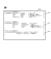
- FIG. 4A shows an example of the setting information table 141
- FIG. 4B shows an example of the setting change data group 143b
- 5A shows an example of the setting information table a
- FIG. 5B shows an example of the setting information table B
- 6A shows an example of the module list M1
- FIG. 6B shows an example of the module list M2.
- Diagram showing an example of API group of object data operation interface 125 Flow chart showing periodic processing of execution control unit 14
- Flow chart showing object data update processing Flow chart showing completion notification reception processing
- Diagram showing an example of an object data update operation request message Diagram to explain the operation example of dynamic layout change A diagram showing an example of a setting change data group 143p in the first modification Functional block diagram of development system 1a in the second embodiment
- Functional block diagram of the operation device 6 A figure showing an example of setting information data group 141a of vehicle control device 2 in a 2nd embodiment Functional block diagram of development system 1a for debugging the map fusion operation unit 132
- Functional block diagram of the operation device 6 for debugging the map fusion operation unit 132 The figure which shows an example of the setting information data group 141a in FIG.
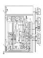
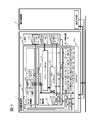
- FIG. 1 is a functional block diagram showing an example of a configuration of a vehicle system 1 including a vehicle control device.
- the vehicle system 1 is a system that is mounted on a vehicle and performs appropriate driving support or traveling control after recognizing a situation of an obstacle such as a traveling road or a surrounding vehicle around the vehicle.
- the vehicle system 1 includes a vehicle control device 2 a, a vehicle control device 2 b, a sensor group 3, an actuator group 4, and a map information management device 5.
- the sensor group 3 includes a sensor A indicated by a symbol 3a and a sensor B indicated by a symbol 3b. However, the sensor group 3 may be configured by three or more sensors.
- the actuator group 4 includes an actuator A indicated by reference numeral 4a and an actuator B indicated by reference numeral 4b. However, the actuator group 4 may be configured by three or more actuators.
- the vehicle control device 2a and the vehicle control device 2b are collectively referred to as “vehicle control device 2".
- the vehicle control device 2 is, for example, an electronic control unit (ECU) mounted on a vehicle.
- the vehicle control device 2a includes a processing unit 10a, a storage unit 40a, and a communication control unit 50a.
- the vehicle control device 2b includes a processing unit 10b, a storage unit 40b, and a communication control unit 50b.
- the processing unit 10a and the processing unit 10b are collectively referred to as the “processing unit 10”
- the storage unit 40a and the storage unit 40b are collectively referred to as the “storage unit 40”.
- the communication control unit 50a and the communication control unit 50b are collectively called "the communication control unit 50".
- the vehicle control device 2a and the vehicle control device 2b execute calculations required for automatic driving. That is, automatic driving is realized by cooperative operation of the vehicle control device 2a and the vehicle control device 2b.
- the function which vehicle system 1 realizes in this embodiment is an example, and vehicle system 1 may realize functions other than automatic driving.
- the processing unit 10 includes, for example, a central processing unit (CPU) and a graphics processing unit (GPU).
- the processing unit 10 realizes the function of the vehicle control device 2 by expanding a program stored in the storage unit 40 or a ROM (not shown) into a RAM (not shown) and executing the program.
- part or all of the functions of the processing unit 10 may be realized by an FPGA (Field-Programmable Gate Array) or a hardware circuit.
- the processing unit 10a has a data adaptation unit 11a, a data management unit 12a, a data calculation unit 13a, an execution control unit 14a, and a diagnosis unit 15a as its functions.
- the processing unit 10b has, as its functions, a data adaptation unit 11b, a data management unit 12b, a data calculation unit 13b, an execution control unit 14b, and a diagnosis unit 15b.
- the data adaptation unit 11a and the data adaptation unit 11b are collectively called “data adaptation unit 11”
- the data management unit 12a and the data management unit 12b are collectively called “data management unit 12”
- a data calculation unit 13a and the data operation unit 13b are collectively called “data operation unit 13”
- the execution control unit 14a and the execution control unit 14b are collectively called “execution control unit 14”
- the diagnosis unit 15a and the diagnosis unit 15b are Collectively, it is called “diagnosis unit 15.”
- the data adaptation unit 11 is a functional component group that performs data format conversion between a data format transmitted to and received from another vehicle control device 2 via the communication control unit 50 and a data format handled by the data management unit 12.
- a functional component is a functional block which implements a part of the function which the process part 10 implement
- the data adaptation unit 11a of the vehicle control device 2a is a map corresponding to the sensor A adaptation unit 111 and the sensor B adaptation unit 112 respectively corresponding to the sensor A indicated by the reference numeral 3a and the sensor B indicated by the reference numeral 3b. And a device adaptation unit 113.
- the data adaptation unit 11 b of the vehicle control device 2 b includes an actuator A adaptation unit 114 and an actuator B adaptation unit 115 respectively corresponding to the actuator A indicated by reference numeral 4 a and the actuator B indicated by reference numeral 4 b.
- Each of these functional components performs data format conversion between the corresponding external device and the data management unit 12 in accordance with the respective data format.
- the sensor A adaptation unit 111, the sensor B adaptation unit 112, the map device adaptation unit 113, the actuator A adaptation unit 114, and the actuator B adaptation unit 115 function.
- Software is stored. That is, as described later, the vehicle control device 2a can further cause the actuator A adaptation unit 114 and the actuator B adaptation unit 115 to function.
- the data management unit 12 manages data using a data format (hereinafter, "object data") abstracted as described later. Therefore, if the operation of the data adaptation unit 11 is described in detail, the functions of each functional component of the data adaptation unit 11 include the following two.
- the first function is to convert the data format of data acquired from another vehicle control device 2 through the communication control unit 50, generate object data, and output the object data to the data management unit 12.
- the second function is to convert the data format of the object data output from the data management unit 12 and to generate data to be transmitted to another vehicle control device 2.
- the data management unit 12 transmits / receives an object data operation request to / from the data management unit 12 of another vehicle control device 2 and a function of managing and operating object data stored in the storage unit 40 of the vehicle control device 2
- a functional part group having a function and a function for providing a common interface to other functional parts.
- the data management unit 12 manages and operates data on the storage unit 40 in units of object data that is a set of data corresponding to a predetermined target element.
- the “target element” is a conceptual target commonly expressed by individual information elements grouped together as object data, and corresponds to, for example, a detection target of the sensor group 3 or a control target of the actuator group 4.
- individual environmental elements obstacles, road shapes, traffic rules, etc.
- recognized by the external world sensor correspond to the target elements. That is, it is preferable not to abstract hardware itself as an external sensor but to abstract data in units of an environmental element that is a detection target of the external sensor and use it as object data.
- the data management unit 12 includes an object data operation execution unit 121, an object data operation execution control unit 122, a setting information management unit 123, an object data operation interface 125, and a setting interface 126.
- the object data operation execution unit 121 performs data operation on the object data group 142 managed on the storage unit 40 based on the data operation request received by the data management unit 12 from another functional component. This data manipulation request is input via the object data manipulation interface 125. When the data management unit 12 performs data manipulation, the data management unit 12 returns the result to the transmission source of the data manipulation request.
- the data manipulation of object data includes not only updating of object data, that is, registration, overwrite, and deletion, but also retrieval of object data.
- the object data operation execution control unit 122 is responsive to an object data operation request accompanied by writing to object data received by the data management unit 12 from another functional component, ie, an update operation, to the storage unit 40 of the vehicle control device. It is determined whether it is necessary to write data or to transfer data to another vehicle control device. At this time, the object data operation execution control unit 122 refers to a setting information data group 141 which will be described later and determines whether or not these items are necessary. This data manipulation request is input via the object data manipulation interface 125. If the object data operation execution control unit 122 determines that data writing is necessary, the object data operation execution control unit 122 passes the object data operation request to the object data operation execution unit 121. Thus, the write operation to the requested object data group 142 is performed.
- the object data operation execution control unit 122 determines that transfer to another vehicle control device is necessary, the object data operation execution unit 121 extracts object data satisfying a predetermined condition through the object data operation execution unit 121, that is, a search operation And outputs the object data operation request to the network via the communication control unit 50. Therefore, by appropriately setting the setting information data group 141, the functional parts of the data adaptation unit 11 and the data calculation unit 13 are not corrected, in other words, without correcting the program or reconfiguring the hardware. It becomes possible to control the writing place of the object data by them.
- the object data operation execution control unit 122 receives the notification from the execution control unit 14 and extracts object data satisfying a predetermined condition via the object data operation execution unit 121, and the object via the communication control unit 50. It also has a function of outputting a write operation request for data to the network.
- the setting information management unit 123 is a functional component that controls acquisition or change of the setting information data group 141 in accordance with a request that the data management unit 12 receives from the execution control unit 14 via the setting interface 126.
- the object data operation interface 125 is an API (Application Programming) for other functional component groups such as the data adaptation unit 11, the data operation unit 13, and the execution control unit 14 to use the object data operation function provided by the data management unit 12. Interface). Although each object data constituting the object data group 142 has a different data structure depending on the target element, the object data manipulation interface 125 provides an interface for enabling arbitrary object data to be manipulated by a common manipulation method. Do.
- API Application Programming
- the setting interface 126 is an interface for enabling another functional component group such as the execution control unit 14 to acquire or change the setting information data group 141 defining the behavior of the data management unit 12. provide.
- the data calculation unit 13 is an application group for realizing the function of the vehicle control device 2.
- the data operation unit 13 is a functional component group that performs operation based on data input from the object data operation interface 125 of the data management unit 12 and outputs data obtained by the operation to the object data operation interface 125.
- Arithmetic processing for realizing complicated functions such as automatic operation is composed of a plurality of processing blocks, and the data computing unit 13 is composed of a plurality of functional parts corresponding to each processing block. That is, in the present embodiment, the automatic driving function is configured by three functional parts, that is, a sensor fusion operation unit 131, a map fusion operation unit 132, and a traveling control operation unit 133.
- the sensor fusion operation unit 131 and the map fusion operation unit 132 are mounted on the vehicle control device 2a, and the travel control operation unit 133 is mounted on the vehicle control device 2b. Based on the various information detected by the sensor group 3, the control information of the automatic driving in the vehicle on which the vehicle control device 2 is mounted is calculated by the arithmetic processing performed by each functional component, and is output to the actuator group 4.
- the sensor fusion operation unit 131 performs identification / integration processing of object data for the same target element detected by a plurality of external sensors included in the sensor group 3 and interpolation processing of missing data based on time series information.
- the map fusion operation unit 132 collates the object data identified and integrated by the sensor fusion operation unit 131 with the information of the map data acquired from the map information management device 5, and transmits the object data to the information of the map data (for example, other vehicles Processing of adding the lane ID in which the vehicle is traveling etc. as an attribute.
- the traveling control calculation unit 133 determines the driving behavior, the traveling trajectory, the speed profile, and the like of the vehicle based on the calculation results of the sensor fusion calculation unit 131 and the map fusion calculation unit 132.
- the traveling control calculation unit 133 also calculates control information for the actuator group 4 based on the determined information, and outputs the calculation result to the data management unit 12 (12b in the case of FIG. 1).
- the control information output to the data management unit 12 is converted into a communication data format corresponding to each actuator by the actuator A adaptation unit 114 and the actuator B adaptation unit 115 of the data adaptation unit 11, and the communication control unit 50b Output to the network via
- the execution control unit 14 is a functional component that controls the execution of each functional component that accesses the data management unit 12, such as functional components of the data adaptation unit 11 and the data calculation unit 13.
- the execution control unit 14 calls a function for executing an operation of each functional component accessing the data management unit 12, that is, an execution function in accordance with the order described in the module list to be described later, a series of operations of the vehicle control device 2 Implement the process.
- the execution control unit 14 refers to the setting information data group 141 via the setting interface 126 of the data management unit 12 and determines whether or not execution of each functional component accessing the data management unit 12 is necessary.
- the execution control unit 14 shifts to processing of the next functional component without calling an execution function for a functional component which is set to be not required to be executed.
- the diagnosis unit 15 is a functional component that diagnoses the state of its own vehicle control device 2 or an external device connected via a network and detects a failure.
- the failure in the own apparatus can be detected by monitoring the internal state with, for example, a watchdog timer.
- the failure of the external device can be detected, for example, by a technique such as keep alive.
- the diagnostic unit 15 notifies the execution control unit 14 when it detects various failures.
- the storage unit 40 is configured to include, for example, a storage device such as a hard disk drive (HDD), a flash memory, a read only memory (ROM), and a memory such as a RAM.
- the storage unit 40 stores a program processed by the processing unit 10 and data groups necessary for the processing, that is, a setting information data group 141, an object data group 142, and a setting change data group 143.
- the storage unit 40 is also used as a main storage device when the processing unit 10 executes a program, for temporarily storing data necessary for the computation of the program.
- the setting information data group 141 is a set of data related to setting information that defines the behavior of the data management unit 12.
- the object data group 142 is a set of object data managed by the data management unit 12 on the storage unit 40.
- the setting change data group 143 is a set of data to be referred to when the execution control unit 14 changes the setting information data group 141 dynamically. Specific examples of the setting information data group 141, the object data group 142, and the setting change data group 143 will be described later.
- the communication control unit 50 includes, for example, a network card or the like conforming to a communication standard such as IEEE 802.3 or CAN (Controller Area Network).
- the communication control unit 50 exchanges data with other devices in the vehicle system 1 based on various protocols.
- the interface for data transmission and reception provided by the communication control unit 50 is configured in a format that does not depend on the hardware of the vehicle control device 2 or the connection with the external device.
- an interface for abstracting and handling the hardware device of the vehicle control device 2 is provided by the device driver group, and a general-purpose communication protocol such as TCP / IP operates thereon.
- TCP / IP operates thereon.
- the communication control unit 50 is described separately from the processing unit 10 in FIG. 1, a part of the processing of the communication control unit 50 may be executed in the processing unit 10.
- a hardware device equivalent in communication processing may be located in the communication control unit 50, and other device drivers, communication protocol processing, etc. may be located in the processing unit 10.
- the interface for transmitting and receiving data does not change, the behavior of functional component groups of the data adaptation unit 11, data management unit 12, data operation unit 13, and execution control unit 14 in the processing unit 10 changes. There is nothing to do.
- the sensor group 3 is a set of an external sensor group which is a device for detecting the state around the vehicle, and an internal sensor group which is a device for detecting the state of the vehicle.
- the external sensor group is, for example, a camera device, a millimeter wave radar, a laser radar, and a sonar.
- the state of the vehicle includes, for example, a traveling speed, a steering angle, an operation amount of an accelerator, and an operation amount of a brake.
- Each of the devices constituting the sensor group 3 outputs the detected information on the in-vehicle network.
- the external sensor group is an environmental element such as other vehicles existing in a predetermined range from a vehicle, an obstacle such as a bicycle, a pedestrian, or a falling object, a road shape such as a white line or a road end, and a traffic rule such as a road sign or signal Detect and output.
- sensor group 3 includes sensor A indicated by reference numeral 3a and sensor B indicated by reference numeral 3b.
- the actuator group 4 is a device group that controls control elements such as steering, brake, and accelerator that determine the movement of the vehicle.
- the actuator group 4 controls the movement of the vehicle based on the operation information of the steering wheel, the brake pedal, the accelerator pedal and the like by the driver and the control information output from the vehicle control device 2.
- the map information management device 5 is a device that manages and provides digital map information around the vehicle, and is, for example, a navigation device.
- the map information management device 5 includes, for example, digital road map data representing an entire predetermined area or an area around the vehicle, and is based on the position information of the vehicle determined through a global navigation satellite system (GNSS) receiver or the like. , Identify the map position (road on which the vehicle is traveling, lanes, etc.) on the map data. Further, the map information management device 5 provides the vehicle control device 2 with map data of the specified map position of the vehicle and its surroundings.
- GNSS global navigation satellite system
- processing functional components constituting the processing unit 10 in the vehicle control device 2 according to the present embodiment
- the processing functional component is configured to deliver and receive data via the data management unit 12. Therefore, even if the arrangement of processing function components in the vehicle control device 2a and the vehicle control device 2b is changed, there is no change in that each data management unit 12 is an interface for data input / output of the processing function components.
- the data management unit 12 controls the writing location of the object data output from each functional component based on the setting information data group 141. Therefore, even if the layout relationship of each functional component that performs data calculation on the vehicle control device 2 is changed due to a change in design or hardware configuration, the influence is limited as follows. That is, even if the arrangement of the functional parts is changed, the processing unit 10 appropriately sets the setting information data group 141 so that the series of arithmetic processing in the vehicle system 1 can be performed without changing the input / output interface of the functional parts. realizable. That is, the static arrangement change of the functional parts can be realized without modifying the functional parts.
- the execution control unit 14 can dynamically control the execution of each functional component accessing the data management unit 12 based on the setting information data group 141. That is, since it is possible to interlock and switch the execution of each functional component and the arrangement of the object data according to it, the following advantages are obtained.
- the advantage is that, by appropriately changing the setting information data group 141 via the setting interface 126, the arrangement change of functional parts, that is, the dynamic arrangement change can be realized while continuing the series of arithmetic processing in the vehicle system 1. It can be done.
- the data adaptation unit 11 that converts the data format between the communication control unit 50 and the data management unit 12 is described separately from the data operation unit 13. However, they are common in that they perform predetermined operations on input data and generate output data. Therefore, it is also possible to treat the data adaptation unit 11 as a part of the data calculation unit 13. In that case, the functional component group of the data calculation unit 13 delivers data via the communication control unit 50 or the data management unit 12.
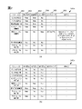
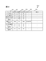
- FIG. 2 is a diagram showing an example of setting information stored in the setting information data group 141.
- FIG. 2 (a) shows the setting information data group 141a stored in the vehicle control device 2a
- FIG. 2 (b) shows the setting information data group 141b stored in the vehicle control device 2b.
- the setting information data group 141 is stored in the storage unit 40, and is a set of data related to setting information that defines the behavior of the data management unit 12.
- the setting information management unit 123 of the data management unit 12 reads the setting change data group 143 when the vehicle control device 2 is activated, and sets the setting information data group 141 on the memory based on the setting information table corresponding to the activation. .
- FIG. 1 shows the setting information data group 141a stored in the vehicle control device 2a
- FIG. 2 (b) shows the setting information data group 141b stored in the vehicle control device 2b.
- the setting information data group 141 is stored in the storage unit 40, and is a set of data related to setting information that defines the behavior
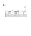
- the setting information data group 141 is composed of a plurality of records, and each record has a module ID 301, an execution necessity 302, a storage necessity 303, an output necessity 304, an output timing 305 and a search formula 306. It has a field.
- the module ID 301 information for identifying functional components of the data adaptation unit 11 that accesses the data management unit 12 and the data operation unit 13 is stored.
- the functional component names shown in FIG. 1 such as “sensor A compatible unit” are described in FIG. 2, in practice, an identifier linked to each functional component, for example, a functional component ID, is used.
- the functional component specified by the value of the field of the functional component ID in a certain record will be referred to as “target functional component”.
- the execution necessity 302 information indicating whether or not to execute the calculation of the target functional component in the vehicle control device is stored.
- the vehicle control device processes a write operation request for object data from the target functional component is stored.
- information indicating whether or not to transfer a write operation request of object data from the functional component to an external device connected via a network is stored.
- an identifier of an output destination for example, an IP address or a host name may be described. In that case, for example, if the output destination information is not described, transfer is not necessary, and if the output destination is described, transfer is performed to the device corresponding to the output destination.
- the field of output timing 305 is set when “Yes” is stored in the field of output necessity 304.
- information indicating the timing of transfer to the external device is stored. For example, “when the operation is completed” or “when the operation is performed” is stored in the field of the output timing 305.
- “When calculation is completed” means that transfer is executed when calculation processing of the target functional component is completed.
- the “operation execution time” means that transfer is performed when each object data write operation requested from the target functional component is performed.
- the field of the search expression 306 is set when “Yes” is stored in the field of the output necessity 304.
- a conditional statement for extracting a transfer target to the external device is stored.
- the values of the fields of the search expression 306 are linked to the values of the fields of the output timing 305 as follows.
- the search stored in the field of the search formula 306 is applied to the entire object data group 142 stored in the storage unit 40.
- the search stored in the field of search expression 306 is applied to the object data for which the write request has been made from the target functional component. Ru.
- conditional sentence created according to a predetermined grammar is stored.
- the conditional statement is expressed by, for example, a combination of a key string specifying a data element of object data and a search expression parameter, a calculation operator, a logical operator, a comparison operator, and the like.
- conditional expression represents a search expression for extracting object data whose data source is “fusion” and whose relative distance is less than 100 m.
- the first two of the three search parameters described above represent the parameters related to the sort of the search results, and specify the sort arrangement order and the target to be sorted. In this example, the values are sorted in ascending order with respect to the value of x 2 + y 2 .
- the third search parameter specifies the upper limit value of the number of object data to be output.
- up to 20 object data can be transmitted.
- These conditional expressions make it possible to extract and transfer only necessary object data, and at the same time, even if the number of corresponding object data is too large, the upper limit of the number of transfers is based on a predetermined priority. It becomes possible to suppress.
- the expression form of the search expression 306 is not limited to this, and may be expressed by SQL (Structured Query Language) or the like.
- SQL Structured Query Language
- FIG. 2 shows an example of setting information data groups 141a and 141b of the vehicle control devices 2a and 2b, this corresponds to the setting information in the vehicle system 1 shown in FIG. That is, in the setting information data group 141a shown in FIG. 2A, the sensor A adaptation unit 111, the sensor B adaptation unit 112, the map device adaptation unit 113, the sensor fusion operation unit 131, and the map fusion operation unit 132 in the vehicle control device 2a. Since it is operating, the value of the execution necessity 302 corresponding to them is set to “Yes”. Further, since the object data necessary for the calculations of the sensor fusion calculation unit 131 and the map fusion calculation unit 132 need to be stored in the object data group 142a of the storage unit 40a, the following settings are made.
- FIG. 3 is a view showing an example of object data stored in the object data group 142.
- the object data group 142 is a set of object data stored in the storage unit 40 and managed by the data management unit 12.
- the object data group 142 has a plurality of records, and each record corresponds to one object data.
- object data to be described in a certain record is referred to as “target object data”.
- the record is also referred to as a "data entry”.
- Each record of the object data group 142 is unique information in which different information is stored according to the ID 201, data source 202, object type 203, time stamp 204, relative position 205, relative velocity 206, and data source and type of target element. It consists of 207.
- a key character string that can be specified in the field of the search expression 306 of the setting information data group 141 is set. That is, “id” for ID 201, “datasrc” for data source 202, “objtype” for object type 203, “timestamp” for time stamp 204, "x” and “y” for relative position 205, relative In the speed 206, "v x “ and “v y " are set.
- predetermined key character strings are assigned to data elements stored in the unique information 207, respectively.
- an identifier for identifying a target element indicated by target object data is stored.
- the same value is set in the field of the ID 201 for a plurality of object data indicating the same target element, for example, the same vehicle.
- the values are set so that there is no duplication in the entire object data group 142.
- uniqueness may be guaranteed by combination with the data source 202 or the like.
- the field of the timestamp 204 stores time information on target object data.
- the time information stored in the field of the time stamp 204 corresponds to, for example, the time when the target object data is detected when the generation source of the target object data represented by the data source 202 is a sensor included in the sensor group 3.
- the time stamp 204 may store other time information, such as an update time of target object data in the storage unit 40, according to a policy of time management of object data in the vehicle control device 2.
- the field of the relative position 205 stores information indicating the relative position of the target element indicated by the target object data with respect to the vehicle.
- the coordinates of the relative position are expressed, for example, in an xy coordinate system centered on the vehicle, and the x-axis is a reference point of the vehicle, for example, a central axis passing through the center of gravity of the vehicle in the front-rear direction
- the y-axis is a central axis (positive in the left direction) passing through the reference point of the vehicle in the left-right direction.
- information indicating the relative speed of the target element indicated by the target object data with respect to the vehicle is stored.
- the coordinate axis of the relative velocity is common to the relative position 205.
- data different for each object data is stored according to the combination of the data source 202 and the object type 203.
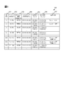
- FIG. 4 is a diagram showing an example of the setting change data group 143.
- FIG. 4A is a view showing an example of the setting change data group 143a
- FIG. 4B is a view showing an example of the setting change data group 143b.
- the setting change data group 143 is stored in the storage unit 40.
- the setting change data group 143 is a set of data to be referred to when the execution control unit 14 changes the setting information data group 141 dynamically.
- the setting change data group 143 includes a plurality of records, and each record stores an event serving as a trigger for changing the setting and setting information after the change.
- each record of the setting change data group 143 has fields of an event type 401, change destination setting information 402, and a module list 403.
- the field of the event type 401 stores information indicating an event serving as a trigger for changing the setting.
- “Device start” means a start event of the vehicle control device 2.
- the “vehicle control device 2b failure” means a failure detection event of the vehicle control device 2b.
- “Vehicle control device 2b return” means an event in which it is detected that the vehicle control device 2b has returned through a restart or the like after failure.
- the setting information is information corresponding to the setting information data group 141.
- the field of the module list 403 stores the name of the module list used after the event occurrence of the event type 401.
- the module list is a list in which functional components are arranged in order of execution.
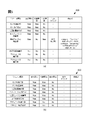
- FIG. 5A shows an example of the setting information table A indicated by reference numeral 410
- FIG. 5B shows an example of the setting information table B indicated by reference numeral 420
- the setting information table A indicated by reference numeral 410 has the same structure and stored information as the setting information data group 141a shown in FIG.
- the configuration information table B indicated by reference numeral 420 has the same structure as that of the configuration information data group 141a, but the stored information is different. An operation example with reference to FIG. 5 will be described later.
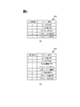
- FIG. 6A shows an example of the module list M1
- FIG. 6B shows an example of the module list M2.
- FIG. 6 corresponds to FIG. That is, the module type for which “YES” is stored in the field of necessity of execution in FIG. 5A, that is, the functional component is described in the module list M1 of FIG. 6A.
- the module type for which “YES” is stored in the field of necessity of execution in FIG. 5B, that is, the functional component is described in the module list M2 of FIG. 6B.
- the order of description is the same in FIG. 5 and FIG.
- the order of description of functional parts in the setting information table and the order of execution of functional parts have nothing to do with each other.
- a pseudo code group C501 shown in FIG. 7 represents a part of the header file when the object data operation interface 125 is described in C language.
- the pseudo code group C 501 includes a pseudo code 511 representing an API for updating object data, a pseudo code 512 representing a search API for object data, and a pseudo code 513 representing a module event notification API. The following describes the APIs represented by these pseudo codes.
- UpdateData which is an update API for object data represented by the pseudo code 511, is an API for performing an update operation on the object data group 142 of a predetermined vehicle control device 2 of the vehicle system 1.
- the update operation on the object data group 142 includes a “registration operation”, an “overwrite operation”, and a “deletion operation”.
- the registration operation is an operation of inserting new object data into the object data group 142.
- the overwrite operation is an operation of overwriting predetermined object data stored in the object data group 142 with new object data.
- the delete operation is an operation to delete predetermined object data stored in the object data group 142.
- the argument of the update API is "module ID” which is a module ID identifying a functional component that has called the API, "dataSize” which is a data length of object data to be operated, It is configured by "data” which is an address of object data to be operated and "mode” which is an operation mode for identifying the type of update operation to be executed.
- the module ID in this argument corresponds to the module ID 301 in FIG.
- the data length and the address of the object data of the operation target are stored as argument values only when the operation mode is a registration operation or an overwrite operation.
- argument information is passed to the object data operation execution control unit 122. Since the vehicle control device 2 on which the specified update operation is executed is determined based on the setting of the setting information data group 141 as described above, the object data group on the vehicle control device 2 for which the API is called is not necessarily required. It does not necessarily apply to 142. When applied to the object data group 142, argument information is passed to the object data operation execution unit 121, and the specified update operation is performed.
- SearchData which is a search API for object data represented by the pseudo code 512
- the arguments of the search API are “module ID” which is a module ID, “searchCond” which is a search expression, and “dataSize, data” which is information of a buffer storing a search result. including.
- the search formula of the API corresponds to the search formula 306 of FIG.
- argument information is passed to the object data manipulation execution unit 121.
- the object data operation execution unit 121 analyzes and interprets the character string of the passed search expression according to a predetermined grammar, and extracts a list of object data that meets the predetermined condition from the object data group 142.
- the sort condition is set in the search expression, the sorted result is stored in the buffer and returned to the caller.
- the module event notification API “notifyModuleEvent” represented by the pseudo code 513 is an API for notifying the data management unit 12 of an event related to the specified module ID.
- the argument of the API is configured by "module ID” which is a module ID and "notify Type” which is a notification type.
- the notification type in this argument for example, “calculation execution completion notification” can be mentioned.
- the calculation execution completion notification is used when notifying the data management unit 12 that the calculation execution of the functional component corresponding to the module ID in this argument is completed.
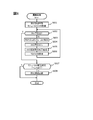
- FIG. 8 is a flowchart illustrating periodic processing of the execution control unit 14 in the vehicle control device 2.
- the execution control unit 14 executes periodic processing shown in FIG. 8 at a predetermined time interval, for example, in a cycle of 100 ms.
- the functional parts are also referred to as "modules”.
- the execution control unit 14 first acquires a module list M to be subjected to execution control in S601.
- this module list M is a copy of the module list stored in the field of the module list 403 in the setting change data group 143.
- the preceding event is “device activation”
- a copy of the module list M1 is acquired as the module list M. Since the module list M is a copy of the module list M1, a part of the module list M is deleted below, but this process does not affect the module list M1.
- the execution control unit 14 determines whether the module list M is an empty set. If it is determined that the module list M is not an empty set, the process proceeds to S603, and if it is determined that the module list M is an empty set, the process proceeds to S607. In S603, the execution control unit 14 acquires the top module m of the module list M. At S604, the execution control unit 14 calls the execution function of the module m and executes the operation of the module m. Then, when execution of the operation is completed, the execution control unit 14 uses the module event notification API of the object data operation interface 125 of the data management unit 12 shown in FIG. (S605), and deletes the module m on which the operation has been executed from the module list M (S606), and the process returns to S602.
- the module list M becomes empty, that is, an empty set, and thus the process proceeds to S607.
- the execution control unit 14 determines the presence or absence of the module placement change event.
- the module arrangement change event corresponds to the event type 401 of the setting change data group 143 in FIG. 4 and is detected by the diagnosis unit 15. If it is determined that there is no module placement change event (S607: N), the processing shown in FIG. 8 is ended. If it is determined that a module layout change event has occurred (S607: Y), the execution control unit 14 changes the setting information (S608) and ends the process shown in FIG.
- the execution control unit 14 refers to the setting change data group 143 to specify the change destination setting information 402 corresponding to the event, and the setting information management unit using the setting interface 126 of the data management unit 12.
- the setting information data group 141 is rewritten via 123.
- one cycle of arithmetic processing for realizing the function of the vehicle control device 2, that is, application processing is performed.
- the function shown in FIG. 8 is periodically executed to realize the function of ADAS or automatic driving in the vehicle system 1.
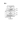
- FIG. 9 is a flowchart showing object data update processing by the object data operation execution control unit 122 of the data management unit 12.
- the data management unit 12 executes the process shown in FIG. 9 when the above-described object data update API is called by the functional components of the data adaptation unit 11 or the data calculation unit 13.
- the object data operation execution control unit 122 acquires an update operation request for object data from the module m (S701). This corresponds to the call of the update API by the data adaptation unit 11 and the data operation unit 13, and the update operation request for object data corresponds to the data group passed as an argument of the update API.
- the object data operation execution control unit 122 refers to the storage necessity 303 of the data entry corresponding to the module m in the setting information data group 141 in S702, and sends the object data requested based on the update operation request. It is determined whether to store in the object data group 142 of the device.
- the object data operation execution control unit 122 determines that "No” is stored in the field of the storage necessity 303 of the module m (S702: N), it proceeds to S704 without executing the update operation. If the storage necessity 303 of the module m is "Yes" (S702: Y), the update operation request is passed to the object data operation execution unit 121, and the process proceeds to S703.
- the object data operation execution unit 121 executes data operation on the object data group 142 stored in the storage unit 40 according to the instruction of the update operation request, and proceeds to S704.
- the data operation includes “registration operation”, “overwrite operation”, and “deletion operation”, but all correspond to the object data of the object of the update operation request from the object data group 142 Identify the entry and execute the next specified operation (registration, overwrite, delete).
- the identification of the data entry is performed by a combination of a predetermined data element or a plurality of data elements included in the object data, for example, a combination of the ID 201 and the data source 202 in FIG.
- the object data operation execution control unit 122 refers to the output necessity 304 of the data entry corresponding to the module m in the setting information data group 141, and outputs the update operation request as an object data update operation request message to the outside. To judge. If the object data operation execution control unit 122 determines that the output necessity 304 of the module m is "No" (S704: N), the process shown in FIG. 9 is ended. If the object data operation execution control unit 122 determines that the output necessity 304 of the module m is "Yes" (S704: Y), the process proceeds to S705.
- the object data operation execution control unit 122 refers to the output timing 305 of the data entry corresponding to the module m in the setting information data group 141, and the setting value is “when the operation is performed” or “when the operation is completed”. Determine if there is. If it is determined that the setting value of the output timing 305 is “at the time of calculation completion” (S 705: N), the processing shown in FIG. 9 is ended. If the object data operation execution control unit 122 determines that the setting value of the output timing 305 is "during operation execution" (S705: Y), the process proceeds to S706.
- the object data operation execution control unit 122 refers to the search formula 306 of the data entry corresponding to the module m in the setting information data group 141, and confirms whether or not the search formula is described in the field of the search formula 306. .
- the object data operation execution control unit 122 determines that the search expression is not described (S706: N)
- the processing proceeds to S707, applies the search expression described for the object data of the target of the update request, Extract object data to be transferred. Then, the object data operation execution control unit 122 generates a transfer update operation request corresponding to the object data to be transferred, and transfers it as an object data update operation request message to the outside of the device (S709). End the process shown.
- FIG. 10 is a flowchart showing a completion notice reception process, which is a process when the data management unit 12 receives a calculation execution completion notice.
- the completion notification reception process shown in FIG. 10 is executed by the execution control unit 14 when the above-described module event notification API is called.
- the object data operation execution control unit 122 receives an operation execution completion notification of the module m from the execution control unit 14. This reception corresponds to a call of the module event notification API for which “operation execution completion notification” is specified as the notification type of argument.
- the object data operation execution control unit 122 refers to the timing 305 of the data entry corresponding to the module m in the setting information data group 141, and determines whether or not the setting value is "completion of calculation”. If the object data operation execution control unit 122 determines that the setting value is not “after the completion of the operation” (S802: N), the process shown in FIG. 10 is ended. If the object data operation execution control unit 122 determines that the setting value is “after the completion of the operation” (S802: Y), the process proceeds to S803.
- the object data operation execution control unit 122 refers to the search expression 306 of the data entry corresponding to the module m in the setting information data group 141, and based on the set search expression, the object to be an object from the object data group 142 Get data Specifically, the object data operation execution control unit 122 generates a search operation request using the search expression, and passes it to the object data operation execution unit 121. Then, the object data operation execution unit 121 executes a search operation on the object data group 142 of the storage unit 40 according to the search operation request, and returns the extracted result to the object data operation execution control unit 122.
- the object data operation execution control unit 122 In S804, the object data operation execution control unit 122 generates a transfer update operation request corresponding to the object data acquired in S803, transfers it as an object data update operation request message to the outside of the device, and the process shown in FIG. Finish.
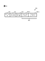
- FIG. 11 is a diagram showing an example of an object data update operation request message 900 transmitted by the vehicle control device 2. However, in FIG. 11, illustration of header information and the like regarding the communication protocol is omitted.
- the object data update operation request message 900 includes a module ID 901, an operation type 902, the number of object data 903, and an object data group 904.
- the object data group 904 is composed of object data 904-1, object data 904-2, and object data 904-n.
- the object data update operation request message 900 is information corresponding to an argument of the update API of the object data operation interface 125.
- the vehicle control device 2 having received the object data update operation request message 900 can call the update API of the object data operation interface 125 with the received object data update operation request message 900 as an argument.
- the module ID 901 represents a module ID corresponding to the functional component that has called the update operation, that is, the first argument of the update API pseudo code 511 shown in FIG. 7.
- the operation type 902 represents the operation type of the update operation, that is, the second argument of the update API pseudo code 511 shown in FIG. 7.
- the number of object data 903 represents the number of entries of the object data group 904.
- the object data group 904 is a list of object data to be updated. That is, since the number of object data is “n” in the example shown in FIG. 11, the object data group 904 is composed of object data 904-1, object data 904-2, and object data 904-n.
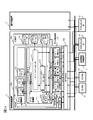
- FIG. 12 is a diagram for explaining an operation example of dynamic layout change in the vehicle system 1.
- the vehicle control device 2b breaks down while the vehicle system 1 is operating in the state of FIG. 1, the application that was operating in the vehicle control device 2b is started up by the vehicle control device 2a, and the function maintenance of the vehicle system 1 is maintained. That is, it shows a state in which fail operation is realized.
- the state in which the vehicle control device 2a and the vehicle control device 2b are operating in cooperation as shown in FIG. 1 is referred to as a coordinated operation state, and as shown in FIG. 12, the vehicle control device 2a operates alone. This state is called a single operation state.
- the calculation result of the vehicle control device 2 a for the data input of the sensor group 3, in other words, the data output to the actuator group 4 needs to be equivalent to FIG. 1.
- the input / output relationship between the functional parts of the data adaptation unit 11a and the data calculation unit 13a of FIG. 12 needs to be equivalent to that of FIG.
- a traveling control calculation unit 133 and adapting units 114 and 115 for the actuator are added on the vehicle control device 2a. Therefore, in the single operation state, at least these functional components also need to be executed on the vehicle control device 2a. Moreover, although it was necessary to transmit the calculation result of the map fusion calculating unit 132 to the vehicle control device 2b until then, the traveling control calculating unit 133 has moved to the vehicle control device 2a, so it is stored in the storage unit 40a of the vehicle control device 2a. Need to change to store. As described above, when dynamically changing the arrangement, it is necessary to make the change while giving consistency between the functional component object to be executed by the vehicle control device and the storage location of the calculation result of each functional component.
- the failure of the vehicle control device 2b is detected by the diagnostic unit 15a of the vehicle control device 2a through the lack of keepalive or the like, and notified to the execution control unit 14a as an event.
- the execution control unit 14a determines that the layout change event of failure of the vehicle control device 2b occurs in S607 of periodic processing shown in FIG. 8 periodically executed (S607: Y), S608 Go to In step S608, the execution control unit 14a refers to the corresponding entry of the setting change data group 143a in FIG. 4 and specifies change destination setting information.
- the execution control unit 14a uses the setting interface 126 of the data management unit 12a to set the setting information data group 141a via the setting information management unit 123. Rewrite to the contents of B.
- the execution control unit 14a executes the processing of FIG. 8 in the next cycle by rewriting the setting information data group 141a, the execution of the module and the storage destination of the data are performed based on the setting information of the setting information table B. Is controlled.
- the traveling control calculation unit 133 and the execution necessity 302 for the adaptation units 114 and 115 for the actuator change to "Yes”
- the main difference between this point and the point where the storage necessity 303 of the map fusion operation unit is changed to “Yes” and the output necessity 304 is changed to “No”.
- the function of the vehicle system 1 can be maintained equivalent to that in FIG.
- the input / output interface of the functional component is an interface provided by the object data operation interface 125 of the data management unit 12 or the communication control unit 50, both are general-purpose interfaces that do not depend on the device. There is no program modification that accompanies the change in location.
- the vehicle control device 2a is communicably connected to the vehicle control device 2b which is an external device.
- the vehicle control device 2a controls the transmission / reception of data with the vehicle control device 2b, the communication control unit 50a, the data management unit 12a managing object data, and object data acquired from the data management unit 12a or the communication control unit 50a.
- a data adaptation unit 11a and a data operation unit 13a including one or more functional components that perform predetermined operations using the predetermined operation and output object data obtained by the predetermined operations to the data management unit 12a, and object data for each functional component
- Setting information data group 141a in which information on the write destination of the data, that is, the values of the fields of storage necessity 303 and output necessity 304 are stored, and a storage unit 40a for storing object data.
- the data management unit 12a controls the writing destination of the object data based on the setting information data group 141a.
- the software configuration can control the execution of the functional component and the output destination of the data, that is, the storage destination using the setting information data group 141 without changing the input / output interface of the functional component. By doing this, it is possible to cope with dynamic layout change of the application. Also, by changing the setting information data group 141, it is possible to cope with static placement change of the application. That is, storage and communication of unnecessary data can be reduced.
- the storage destination of the object data output by the functional component as the calculation result is controlled based on the setting information data group 141.
- the setting information data group 141 manages setting information in association with the functional component of the output source of the object data
- the update operation interface of the functional component may include information for identifying the functional component. . Therefore, each functional component does not need to be aware of the output destination of the object data. For example, even if a functional component using the object data is added or deleted, the functional component of the output source needs to be corrected There is no Therefore, it is possible to flexibly add or delete static or dynamic functional parts.
- a common interface that enables data search operation, update operation, and the like in a versatile manner is adopted as an input / output interface of each functional component involved in arithmetic processing. Therefore, it is possible to uniformly control data transfer between all functional parts involved in arithmetic processing in the execution of calling of the common interface. Thereby, as described above, it becomes possible to easily control the storage destination of data by the setting information. If such a common interface is not used, the data management unit 12 individually generates an interface for each functional component, so the data storage destination etc. are uniformly controlled by setting information etc. It is difficult to do.
- the setting information data group 141a includes, for each functional component, external output necessity information relating to the necessity of outputting object data to the external device, that is, the value of the field of the output necessity 304.
- the data management unit 12a outputs the object data to the vehicle control device 2b via the communication control unit 50a when the external output necessity information is required to be output, that is, "Yes" is stored.
- the vehicle control device 2a includes the operation execution control unit 14a that controls the execution of the functional components.
- the setting information data group 141a includes execution necessity information related to the execution necessity of the functional component, that is, the value of the field of the execution necessity 302.
- the operation execution control unit 14a executes a predetermined operation of the functional component when the execution necessity information needs execution. Therefore, the vehicle control device 2a can easily control the execution of the functional components.
- the storage unit 40a stores a plurality of setting information corresponding to each of the plurality of events, for example, the setting information table A and the setting information table B shown in FIG.
- the data management unit 12a and the operation execution control unit 14a operate based on setting information corresponding to the detected event when any one of a plurality of events is detected. Therefore, the vehicle control device 2a can change the operation to the setting corresponding to the detected event.
- the storage unit 40a stores a setting change data group 143a in which an event and setting information to be applied when the event is detected are associated.
- the data management unit 12a and the operation execution control unit 14a specify the setting information data group 141a to be applied with reference to the setting change data group 143a, and the specified setting It operates based on the information data group 141a. Therefore, the vehicle control device 2a can change the operation with reference to the setting change data group 143a set in advance.
- the event includes “vehicle control device 2 b failure” which is a failure of the traveling control calculation unit 133 which is a functional component operating in the vehicle control device 2 b.
- the setting information table B corresponding to the "vehicle control device 2b failure” includes that the traveling control calculation unit 133 needs to be performed. Therefore, the vehicle control device 2a can maintain the function of the vehicle system 1 by executing the functional components that have been executed in the other device in which the failure is detected.
- a conditional expression for reading out an object to be output to the vehicle control device 2b out of object data managed by the data management unit 12a is included in the field of the search expression 306 for each functional component. be able to. If the search information 306 is included in the setting information data group 141a for the functional component for which the predetermined operation has been performed, the execution control unit 14a selects object data that conforms to the search expression 306 from among the object data managed by the data management unit 12a. Are read out (S804 in FIG. 10) and output to the vehicle control device 2b.
- each functional component involved in the arithmetic processing is configured to extract and acquire data necessary for the search operation from the object data group 142 managed by the data management unit 12. Therefore, if the object data group 142 includes data entries necessary for the operation of the functional component, the data entries necessary in the same manner by the search operation regardless of whether or not other unnecessary data entries are included. It is possible to extract
- the traveling control calculation unit 133 controls the object data operation interface 125 with respect to the object data group 142 a including all object data after execution of the map fusion calculating unit 132. By performing a search operation via, necessary data entries are extracted and acquired.
- the traveling control calculation unit 133 executes the search operation on the object data group 142b, but in the object data group 142b, the data of the map fusion calculation unit 132 in FIG. Only object data matching the conditions of the entry search expression 306 is stored.
- the search expression 306 specified here is equivalent to the search expression specified by the search operation executed by the travel control operation unit 133 because the purpose is to extract and transfer the object data required by the travel control operation unit 133.
- the functional component has a structure that does not use a search operation, it is difficult to obtain the same calculation result without modifying the program because different amounts of object data groups are handled in FIGS. 1 and 12. That is, since the functional parts are configured to acquire data by a search operation, even when data is transferred to another apparatus, even if unnecessary data is transferred, the transfer can be performed without program modification. It can be said that
- the setting information data group 141a includes, in the field of the search expression 306, a conditional expression for selecting an object to be output to the vehicle control device 2b from object data to be output.
- the data management unit 12a extracts target data conforming to the search expression 306 from the object data to be output (S707 in FIG. 9), and outputs the target data to the vehicle control device 2b (S709).
- the setting information data group 141a includes the value of the field of the writing necessity 302 regarding the writing necessity to the storage unit 40a of the object data to be output for each functional component.
- the data management unit 12a executes writing of the object data to be output to the storage unit 40a when the writing necessity information is necessary, and to the storage unit 40a of the object data to be outputted when the writing necessity information is not. Do not write Therefore, the vehicle control device 2a can avoid unnecessary storage of data.
- the data management unit 12b acquires output object data output from the vehicle control device 2a via the communication control unit 50b. Based on the writing necessity information in the setting information of the functional component that has output the object data, execution of writing of the output object data to the storage unit 40b is controlled. For example, in the setting information data group 141b, since the value of the field of the storage necessity 303 of the map fusion operation unit 132 is "Yes", the storage unit 40b stores object data output by the map fusion operation unit 132 acquired via the communication control unit 50b. Store in Therefore, the vehicle control device 2a can store data appropriately.
- the diagnosis unit 15 When the diagnosis unit 15 receives a setting change request from the outside via the communication control unit 50, the diagnosis unit 15 may output this to the execution control unit 14. Furthermore, the setting change request received from the outside may be added with additional information, for example, information specifying the setting to be changed.
- FIG. 13 is a diagram showing an example of the setting change data group 143p in the first modification.
- the setting change request received from the outside includes “change command P”, “change command Q”, and “change command R”, and corresponding setting information and module list It is prescribed.
- the event includes reception of a setting change request from the vehicle control device 2b. Therefore, the vehicle control device 2 can change the operation according to the external request. Specifically, the vehicle control device 2 reads an appropriate setting information table from the setting change data group 143p in response to a setting change request from the outside, and determines a module list to be executed thereafter.
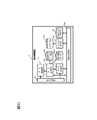
- FIGS. 14 and 15 are functional block diagrams showing a configuration of a development system 1a including a vehicle control device according to a second embodiment of the present invention.
- the configuration of the operation device 6 is shown in FIG.
- the development system 1a is mounted on a vehicle, and includes an operation device 6 in addition to the vehicle control device 2, the sensor group 3, the actuator group 4 and the map information management device 5 shown in the first embodiment.
- the configuration of the vehicle control device 2 is the same as that of the first embodiment, and thus the description thereof is omitted.
- the operation device 6 illustrated in FIG. 15 is, for example, a general-purpose processing device such as a personal computer, and is used by a developer of the vehicle control device 2 to monitor and control the state of the vehicle control device 2.
- the operation device 6 includes a communication control unit 50 c, a log input / output control unit 60, and a setting change operation unit 70.
- the communication control unit 50 c corresponds to the communication control unit 50 a of the vehicle control device 2.
- the data adaptation unit 11c, data management unit 12c, data operation unit 13c, execution control unit 14c, setting information data group 141c, and object data group 142c are the data adaptation unit 11a, data management unit 12a, and the like of the vehicle control device 2. It corresponds to the data operation unit 13a, the execution control unit 14a, the setting information data group 141a, and the object data group 142a.
- the log input / output control unit 60 stores the object data update operation request message output from the vehicle control device 2 on the network as the log data group 161.
- the log input / output control unit 60 also outputs the object data update operation request message acquired from the log data group 161 to the network at a predetermined timing.
- the setting change operation unit 70 provides an operation interface for changing the setting information data group 141 a of the vehicle control device 2 a via the execution control unit 14 a of the vehicle control device 2.
- FIG. 16 is a diagram showing an example of the setting information data group 141 a of the vehicle control device 2.
- the difference between the setting information in the first embodiment and the setting information in the first embodiment is that the value of the field of output necessity 304 is “Yes” and the value of the field of output timing 305 is “when the operation is executed” in some functional parts.
- the value of the field of the storage necessity 303 is also "Yes", which means that the calculation result is output to the outside while being stored in the object data group 142a of the vehicle control device 2.
- This corresponds to the log output of the calculation result of each functional component, and the output data (corresponding to the object data update operation request message 900 in FIG. 11) is acquired by the log input / output control unit 60 of the operation device 6 , Log data group 161 is stored. At this time, each log data is managed in association with the output time information.
- FIGS. 17 and 18 are functional block diagrams showing an example of a system configuration for debugging the map fusion operation unit 132.
- FIG. Here, in the system configuration of FIG. 14, it is assumed that a defect of the map fusion operation unit 132 is found during the operation check of the vehicle control device 2.
- Log data of the calculation result of each functional component before and after the occurrence of the failure is stored in the log data group 161 of the operation device 6.
- the system configurations shown in FIGS. 17 and 18 are the same as the system configurations shown in FIGS. 14 and 15, but functional components which are not operated by debugging described below are shown by broken lines.
- FIG. 17 and FIG. 18, the path through which the main data circulates in debugging is indicated by thick arrows.
- the log input / output control unit 60 outputs log data to the vehicle control device 2 based on time information stored in association with the log data.
- the log data here corresponds to an object data update operation request message. Therefore, it is treated the same as the transfer data of the object data operation execution control unit 122 of the vehicle control device 2, and is passed to the object data operation execution control unit 122 via the object data operation interface 125, and the object data shown in FIG. Update processing is performed.
- FIG. 19 is a diagram showing an example of the setting information data group 141a in FIG. Since the configuration shown in FIG. 17 is for debugging of the map fusion operation unit 132, “No” is set in the field of execution necessity 302 for functional components except for the map fusion operation unit 132 as shown in FIG. . Since the map fusion operation unit 132 uses the output result of the sensor fusion operation unit 131 and the map information provided from the map information management device 5 for the operation, they are required as input data. Therefore, the value of the field of the storage necessity 303 of the map device adaptation unit 113 and the sensor fusion operation unit 131 is set to “Yes”.
- the map fusion operation unit 132 Since the arithmetic processing is performed based on the input data equivalent to the occurrence of the defect, the defect can be reproduced with high probability. This facilitates problem analysis and makes it possible to streamline application debugging.
- the program output can be obtained by appropriately changing the setting information from the operation device, and outputting the log of the operation result output of the functional component and debugging the predetermined application by the log reproduction. It can be realized without modification.
- each process is described as being performed by the same processing unit and storage unit, but may be performed by a plurality of different processing units and storage units .
- processing software having the same configuration is installed in each storage unit, and each processing unit shares the processing and executes the processing.
- each process of the vehicle control apparatus 2 is implement
- the vehicle control device, the sensor group, the map information management device, and the actuator group are described as individual devices, it may be realized by combining any two or more of them as needed. Is also possible. Also, the drawings show control lines and information lines that are considered to be necessary to explain the embodiment, and not necessarily all control lines and information lines included in an actual product to which the present invention is applied. Not necessarily. In practice, almost all configurations may be considered to be mutually connected.
Landscapes
- Engineering & Computer Science (AREA)
- Theoretical Computer Science (AREA)
- Physics & Mathematics (AREA)
- General Physics & Mathematics (AREA)
- General Engineering & Computer Science (AREA)
- Remote Sensing (AREA)
- Radar, Positioning & Navigation (AREA)
- Software Systems (AREA)
- Quality & Reliability (AREA)
- Automation & Control Theory (AREA)
- Computing Systems (AREA)
- Computer Hardware Design (AREA)
- Signal Processing (AREA)
- Computer Networks & Wireless Communication (AREA)
- Aviation & Aerospace Engineering (AREA)
- Mechanical Engineering (AREA)
- Data Mining & Analysis (AREA)
- Databases & Information Systems (AREA)
- Mathematical Physics (AREA)
- Stored Programmes (AREA)
- Traffic Control Systems (AREA)
Abstract
車両制御装置は、外部装置と通信可能に接続された車両制御装置であって、外部装置とのデータ送受信を制御する通信制御部と、オブジェクトデータを管理するデータ管理部と、データ管理部または通信制御部から取得されるオブジェクトデータを用いて所定の演算を行い、所定の演算により得られたオブジェクトデータである出力オブジェクトデータをデータ管理部に出力する1つ以上の機能部品と、機能部品ごとに出力オブジェクトデータの書き込み先に関する情報が格納される設定情報、およびオブジェクトデータを記憶する記憶部とを備え、データ管理部は、出力オブジェクトデータの書込み先を、設定情報に基づいて制御する。
Description
本発明は、車両制御装置に関する。
ネットワークで接続された複数の組込み装置から構成される制御システムにおいて、プログラムの修正なくアプリケーションソフトウェア(以降、アプリケーション)の配置変更に対応可能とする技術が提案されている。この技術は、各組込み装置上で共通して動作するミドルウェアが、アプリケーションが演算に用いるデータの格納先を設定情報に基づいて制御することにより実現される。アプリケーションの配置変更としては、組込み装置の非実行状態の時(設計時や装置停止時等)に行う「静的な配置変更」と、実行状態の時に行う「動的な配置変更」がある。静的な配置変更としては、アプリケーションを異なる装置構成のシステムに適用する場合(例えば、異なる車種への展開)等が例として挙げられる。一方、動的な配置変更が必要となる例としては、制御システム上のある組込み装置が故障した場合に、その故障した組込み装置上で動作していたアプリケーションを他の組込み装置上で立ち上げることにより、制御システムを維持するというフェールオペレーショナルシステム等が挙げられる。
たとえば特許文献1には、他の通信装置との通信手段を備える通信装置において、複数の異なるアプリケーションプログラムを実行する手段と、他の通信装置と共通のプラットフォームプログラムを実行する手段と、データを記憶する記憶手段と、前記プラットフォームプログラムの処理により、前記記憶手段と前記アプリケーションプログラムとのデータの授受、他の通信装置とのデータの送受信、及び前記通信手段により他の通信装置から受信したデータの前記記憶手段への記憶を、他の通信装置と共通に行なう手段と、前記プラットフォームプログラムの処理により、前記記憶手段が記憶したデータの内の一又は複数を用いて他のデータを生成する生成手段とを備え、前記生成手段が生成したデータを前記通信手段により他の通信装置へ送信するようにしてあることを特徴とする通信装置が開示されている。
たとえば特許文献1には、他の通信装置との通信手段を備える通信装置において、複数の異なるアプリケーションプログラムを実行する手段と、他の通信装置と共通のプラットフォームプログラムを実行する手段と、データを記憶する記憶手段と、前記プラットフォームプログラムの処理により、前記記憶手段と前記アプリケーションプログラムとのデータの授受、他の通信装置とのデータの送受信、及び前記通信手段により他の通信装置から受信したデータの前記記憶手段への記憶を、他の通信装置と共通に行なう手段と、前記プラットフォームプログラムの処理により、前記記憶手段が記憶したデータの内の一又は複数を用いて他のデータを生成する生成手段とを備え、前記生成手段が生成したデータを前記通信手段により他の通信装置へ送信するようにしてあることを特徴とする通信装置が開示されている。
特許文献1に記載されている発明では、ネットワーク帯域や各組込み装置の記憶容量を無駄に消費する。
本発明の第1の態様による車両制御装置は、外部装置と通信可能に接続された車両制御装置であって、前記外部装置とのデータ送受信を制御する通信制御部と、オブジェクトデータを管理するデータ管理部と、前記データ管理部または前記通信制御部から取得されるオブジェクトデータを用いて所定の演算を行い、前記所定の演算により得られたオブジェクトデータである出力オブジェクトデータを前記データ管理部に出力する1つ以上の機能部品と、前記機能部品ごとに前記出力オブジェクトデータの書き込み先に関する情報が格納される設定情報、およびオブジェクトデータを記憶する記憶部とを備え、前記データ管理部は、前記出力オブジェクトデータの書込み先を、前記設定情報に基づいて制御する。
本発明によれば、不要なデータの保存や通信を低減することができる。
―第1の実施の形態―
以下、図1~図12を参照して、車両制御装置の第1の実施の形態を説明する。
以下、図1~図12を参照して、車両制御装置の第1の実施の形態を説明する。
(車両システムの構成)
図1は、車両制御装置を含む車両システム1の構成の一例を示す機能ブロック図である。車両システム1は、車両に搭載され、車両の周辺における走行道路や周辺車両等の障害物の状況を認識した上で、適切な運転支援あるいは走行制御を行うためのシステムである。図1に示すように、車両システム1は、車両制御装置2a、車両制御装置2b、センサ群3、アクチュエータ群4、および地図情報管理装置5を含んで構成される。センサ群3は、符号3aで示すセンサAと符号3bで示すセンサBとを含む。ただしセンサ群3は3以上のセンサにより構成されてもよい。アクチュエータ群4は、符号4aで示すアクチュエータAと符号4bで示すアクチュエータBとを含む。ただしアクチュエータ群4は、3以上のアクチュエータにより構成されてもよい。以下では、車両制御装置2aと車両制御装置2bとをまとめて「車両制御装置2」とも呼ぶ。
図1は、車両制御装置を含む車両システム1の構成の一例を示す機能ブロック図である。車両システム1は、車両に搭載され、車両の周辺における走行道路や周辺車両等の障害物の状況を認識した上で、適切な運転支援あるいは走行制御を行うためのシステムである。図1に示すように、車両システム1は、車両制御装置2a、車両制御装置2b、センサ群3、アクチュエータ群4、および地図情報管理装置5を含んで構成される。センサ群3は、符号3aで示すセンサAと符号3bで示すセンサBとを含む。ただしセンサ群3は3以上のセンサにより構成されてもよい。アクチュエータ群4は、符号4aで示すアクチュエータAと符号4bで示すアクチュエータBとを含む。ただしアクチュエータ群4は、3以上のアクチュエータにより構成されてもよい。以下では、車両制御装置2aと車両制御装置2bとをまとめて「車両制御装置2」とも呼ぶ。
車両制御装置2は、例えば、車両に搭載された電子制御装置(ECU:Electronic Control Unit)である。車両制御装置2aは、処理部10aと、記憶部40aと、通信制御部50aとを有する。車両制御装置2bは、処理部10bと、記憶部40bと、通信制御部50bとを有する。ただし以下では、処理部10aと処理部10bとをまとめて「処理部10」とも呼び、記憶部40aと記憶部40bとをまとめて「記憶部40」とも呼び、通信制御部50aと通信制御部50bとをまとめて「通信制御部50」とも呼ぶ。
車両システム1は、自動運転に必要な演算を車両制御装置2a、および車両制御装置2bが実行する。すなわち車両制御装置2aと車両制御装置2bの協調動作により自動運転が実現される。ただし本実施の形態において車両システム1が実現する機能は一例であり、車両システム1は自動運転以外の機能を実現してもよい。
処理部10は、たとえば、CPU(Central Processing Unit:中央演算処理装置)やGPU(Graphics Processing Unit)を含んで構成される。処理部10は、記憶部40または不図示のROMに格納されているプログラムを不図示のRAMに展開して実行することで、車両制御装置2の機能を実現する。ただし処理部10が備える機能の一部または全部は、FPGA(Field-Programmable Gate Array)やハードウエア回路により実現されてもよい。
処理部10aはその機能として、データ適合部11a、データ管理部12a、データ演算部13a、実行制御部14a、および診断部15aを備える。処理部10bはその機能として、データ適合部11b、データ管理部12b、データ演算部13b、実行制御部14b、および診断部15bを備える。以下では、データ適合部11aとデータ適合部11bとをまとめて「データ適合部11」と呼び、データ管理部12aとデータ管理部12bとをまとめて「データ管理部12」と呼び、データ演算部13aとデータ演算部13bとをまとめて「データ演算部13」と呼び、実行制御部14aと実行制御部14bとをまとめて「実行制御部14」と呼び、診断部15aと診断部15bとをまとめて「診断部15」と呼ぶ。
データ適合部11は、通信制御部50を介して他の車両制御装置2と送受信するデータ形式とデータ管理部12で扱うデータ形式との間の、データ形式の変換を行う機能部品群である。ただし機能部品とは、処理部10が実現する機能の一部を実現する機能ブロックであり、CPU、GPU、FPGA、またはハードウエア回路により実現される。
車両制御装置2aのデータ適合部11aは、符号3aで示すセンサA及び符号3bで示すセンサBにそれぞれ対応するセンサA適合部111及びセンサB適合部112と、地図情報管理装置5に対応する地図装置適合部113とを備える。車両制御装置2bのデータ適合部11bは、符号4aで示すアクチュエータA及び符号4bで示すアクチュエータBにそれぞれ対応するアクチュエータA適合部114及びアクチュエータB適合部115を備える。これらの各機能部品が、対応する外部装置とデータ管理部12との間で、それぞれのデータ形式に応じたデータ形式の変換を行う。
ただし車両制御装置2aおよび車両制御装置2bのROMには、センサA適合部111、センサB適合部112、地図装置適合部113、アクチュエータA適合部114、およびアクチュエータB適合部115を機能させるためのソフトウエアが格納されている。すなわち後述するように、車両制御装置2aがさらにアクチュエータA適合部114、およびアクチュエータB適合部115を機能させることも可能である。
なお、データ管理部12では、後述するように抽象化したデータ形式(以下、「オブジェクトデータ」)を用いてデータの管理を行う。そのためデータ適合部11の動作を詳述すれば、データ適合部11の各機能部品の機能は次の2つを含む。すなわち第1に、通信制御部50を介して他の車両制御装置2から取得したデータのデータ形式を変換し、オブジェクトデータを生成してデータ管理部12へ出力する機能である。第2に、データ管理部12から出力されるオブジェクトデータのデータ形式を変換し、他の車両制御装置2への送信するデータを生成する機能である。
データ管理部12は、車両制御装置2の記憶部40に格納されたオブジェクトデータの管理および操作を行う機能と、他の車両制御装置2のデータ管理部12とのオブジェクトデータ操作要求の送受信を行う機能と、他の機能部品に対する共通インタフェースを提供する機能と、を有する機能部品群である。
データ管理部12は、所定の対象要素に対応するデータの集合であるオブジェクトデータを単位として、記憶部40上でデータの管理および操作を行う。なお「対象要素」とは、オブジェクトデータとして一纏めにした個々の情報要素が共通して表現する概念的な対象であり、例えば、センサ群3の検出対象や、アクチュエータ群4の制御対象等が該当する。好ましくは、特に外界センサについては、当該外界センサで認識された個々の環境要素(障害物、道路形状、交通ルール等)が対象要素に該当する。すなわち、外界センサというハードウェアそのものを抽象化するのではなく、外界センサの検出対象である環境要素を単位としてデータを抽象化し、オブジェクトデータとする方式を採ることが好ましい。
(データ管理部)
データ管理部12は、オブジェクトデータ操作実行部121、オブジェクトデータ操作実行制御部122、設定情報管理部123、オブジェクトデータ操作インタフェース125、および設定インタフェース126を備える。
データ管理部12は、オブジェクトデータ操作実行部121、オブジェクトデータ操作実行制御部122、設定情報管理部123、オブジェクトデータ操作インタフェース125、および設定インタフェース126を備える。
オブジェクトデータ操作実行部121は、データ管理部12が他の機能部品から受けたデータ操作要求に基づき、記憶部40上で管理しているオブジェクトデータ群142に対してデータ操作を行う。このデータ操作要求は、オブジェクトデータ操作インタフェース125を介して入力される。データ管理部12は、データ操作を行うとその結果をデータ操作要求の送信元に返す。なおオブジェクトデータのデータ操作には、オブジェクトデータの更新、すなわち登録、上書き、および削除だけでなく、オブジェクトデータの検索が含まれる。
オブジェクトデータ操作実行制御部122は、データ管理部12が他の機能部品から受けたオブジェクトデータへの書込みを伴うオブジェクトデータ操作要求、すなわち更新操作に対して、当該車両制御装置の記憶部40へのデータ書込み要否や、別の車両制御装置に対する転送要否を判断する。この際にオブジェクトデータ操作実行制御部122は、後述する設定情報データ群141を参照してこれらの要否を判断する。このデータ操作要求は、オブジェクトデータ操作インタフェース125を介して入力される。オブジェクトデータ操作実行制御部122は、データ書込みが必要と判断する場合は、当該オブジェクトデータ操作要求をオブジェクトデータ操作実行部121に渡す。これにより、要求されたオブジェクトデータ群142に対する書込み操作が実行される。
オブジェクトデータ操作実行制御部122は、別の車両制御装置に対する転送が必要と判断する場合は、必要に応じてオブジェクトデータ操作実行部121を介して所定の条件を満たすオブジェクトデータの抽出、すなわち検索操作を実行し、通信制御部50を介してネットワークに当該オブジェクトデータ操作要求を出力する。そのため、設定情報データ群141を適切に設定することにより、データ適合部11やデータ演算部13の各機能部品を修正することなく、換言するとプログラムの修正やハードウエアの再構成をすることなく、それらによるオブジェクトデータの書込み場所を制御することが可能となる。
またオブジェクトデータ操作実行制御部122は、実行制御部14からの通知を受けて、オブジェクトデータ操作実行部121を介して所定の条件を満たすオブジェクトデータを抽出し、通信制御部50を介して当該オブジェクトデータに関する書込み操作要求をネットワークに出力する機能も有する。
設定情報管理部123は、データ管理部12が設定インタフェース126を介して実行制御部14から受けた要求に従い、設定情報データ群141の取得または変更を制御する機能部品である。
オブジェクトデータ操作インタフェース125は、データ適合部11、データ演算部13、実行制御部14等の他の機能部品群が、データ管理部12が提供するオブジェクトデータ操作機能を利用するためのAPI(Application Programming Interface)に相当する。オブジェクトデータ群142を構成する各オブジェクトデータは、その対象要素に応じてデータ構造が異なるが、オブジェクトデータ操作インタフェース125は、任意のオブジェクトデータを共通の操作手法で操作可能とするためのインタフェースを提供する。
設定インタフェース126は、実行制御部14等の他の機能部品群が、データ管理部12の振る舞いを規定する設定情報データ群141を取得したり、変更したりすることを可能とするためのインタフェースを提供する。
(データ演算部)
データ演算部13は、車両制御装置2の機能を実現するためのアプリケーション群である。データ演算部13は、データ管理部12のオブジェクトデータ操作インタフェース125から入力されたデータに基づいて演算を行い、演算により得られたデータをオブジェクトデータ操作インタフェース125に出力する機能部品群である。自動運転のような複雑な機能を実現する演算処理は複数の処理ブロックで構成され、データ演算部13は個々の処理ブロックに対応する複数の機能部品で構成されている。すなわち本実施の形態では自動運転機能は3つの機能部品、すなわちセンサフュージョン演算部131、地図フュージョン演算部132、および走行制御演算部133により構成される。そしてこの3つの機能部品は、センサフュージョン演算部131と地図フュージョン演算部132が車両制御装置2aに搭載され、走行制御演算部133が車両制御装置2bに搭載される。これらの各機能部品が行う演算処理により、センサ群3で検出された各種情報に基づき、車両制御装置2が搭載される車両における自動運転の制御情報が演算され、アクチュエータ群4に出力される。
データ演算部13は、車両制御装置2の機能を実現するためのアプリケーション群である。データ演算部13は、データ管理部12のオブジェクトデータ操作インタフェース125から入力されたデータに基づいて演算を行い、演算により得られたデータをオブジェクトデータ操作インタフェース125に出力する機能部品群である。自動運転のような複雑な機能を実現する演算処理は複数の処理ブロックで構成され、データ演算部13は個々の処理ブロックに対応する複数の機能部品で構成されている。すなわち本実施の形態では自動運転機能は3つの機能部品、すなわちセンサフュージョン演算部131、地図フュージョン演算部132、および走行制御演算部133により構成される。そしてこの3つの機能部品は、センサフュージョン演算部131と地図フュージョン演算部132が車両制御装置2aに搭載され、走行制御演算部133が車両制御装置2bに搭載される。これらの各機能部品が行う演算処理により、センサ群3で検出された各種情報に基づき、車両制御装置2が搭載される車両における自動運転の制御情報が演算され、アクチュエータ群4に出力される。
ただし車両制御装置2aおよび車両制御装置2bのROMには、センサフュージョン演算部131、地図フュージョン演算部132、および走行制御演算部133を機能させるためのソフトウエアが格納されている。すなわち後述するように、車両制御装置2aだけでセンサフュージョン演算部131、地図フュージョン演算部132、および走行制御演算部133の全ての演算を行うことも可能である。
センサフュージョン演算部131は、センサ群3に含まれる複数の外界センサで検出した同一の対象要素に対するオブジェクトデータの同定・統合処理、および時系列情報に基づく欠落データの補間処理を行う。
地図フュージョン演算部132は、センサフュージョン演算部131が同定・統合したオブジェクトデータと地図情報管理装置5から取得した地図データの情報とを照合し、当該オブジェクトデータに地図データの情報(例えば、他車両が走行している車線ID等)を属性として付加する処理を行う。
地図フュージョン演算部132は、センサフュージョン演算部131が同定・統合したオブジェクトデータと地図情報管理装置5から取得した地図データの情報とを照合し、当該オブジェクトデータに地図データの情報(例えば、他車両が走行している車線ID等)を属性として付加する処理を行う。
走行制御演算部133は、センサフュージョン演算部131、地図フュージョン演算部132の演算結果に基づいて、当該車両の運転行動や走行軌道、速度プロファイル等を決定する。また走行制御演算部133は、決定したこれらの情報を基に、アクチュエータ群4に対する制御情報を演算し、その演算結果をデータ管理部12(図1の場合は12b)に出力する。なお、データ管理部12に出力された制御情報は、データ適合部11のアクチュエータA適合部114、およびアクチュエータB適合部115によりそれぞれのアクチュエータに対応する通信データ形式に変換され、通信制御部50bを介してネットワークに出力される。
(実行制御部)
実行制御部14は、データ適合部11及びデータ演算部13の機能部品等、データ管理部12にアクセスする各機能部品の実行を制御する機能部品である。実行制御部14は、後述するモジュールリストに記載された順序に従って、データ管理部12にアクセスする各機能部品の演算を実行するための関数、すなわち実行関数を呼び出し、車両制御装置2の一連の演算処理を実現する。その際に実行制御部14は、データ管理部12の設定インタフェース126を介して設定情報データ群141を参照し、データ管理部12にアクセスする各機能部品の実行要否を判断する。実行制御部14は、実行不要と設定されている機能部品については実行関数を呼び出さずに、次の機能部品の処理に移行する。
実行制御部14は、データ適合部11及びデータ演算部13の機能部品等、データ管理部12にアクセスする各機能部品の実行を制御する機能部品である。実行制御部14は、後述するモジュールリストに記載された順序に従って、データ管理部12にアクセスする各機能部品の演算を実行するための関数、すなわち実行関数を呼び出し、車両制御装置2の一連の演算処理を実現する。その際に実行制御部14は、データ管理部12の設定インタフェース126を介して設定情報データ群141を参照し、データ管理部12にアクセスする各機能部品の実行要否を判断する。実行制御部14は、実行不要と設定されている機能部品については実行関数を呼び出さずに、次の機能部品の処理に移行する。
(診断部)
診断部15は、自身の車両制御装置2やネットワークで接続された外部装置の状態を診断し、故障を検出する機能部品である。自身の装置内の故障は、例えば、ウォッチドックタイマー等により内部状態を監視することにより検出可能である。また、外部装置の故障は、例えば、キープアライブ等の手法により検出可能である。診断部15は、各種故障を検出すると実行制御部14に通知する。
診断部15は、自身の車両制御装置2やネットワークで接続された外部装置の状態を診断し、故障を検出する機能部品である。自身の装置内の故障は、例えば、ウォッチドックタイマー等により内部状態を監視することにより検出可能である。また、外部装置の故障は、例えば、キープアライブ等の手法により検出可能である。診断部15は、各種故障を検出すると実行制御部14に通知する。
(記憶部)
記憶部40は、例えば、HDD(Hard Disk Drive)、フラッシュメモリ、ROM(Read Only Memory)などの記憶装置や、RAMなどのメモリを含んで構成される。記憶部40には、処理部10が処理するプログラムや、その処理に必要なデータ群、すなわち設定情報データ群141、オブジェクトデータ群142、及び設定変更用データ群143が格納される。また記憶部40は、処理部10がプログラムを実行する際の主記憶装置として、一時的にプログラムの演算に必要なデータを格納する用途にも利用される。
記憶部40は、例えば、HDD(Hard Disk Drive)、フラッシュメモリ、ROM(Read Only Memory)などの記憶装置や、RAMなどのメモリを含んで構成される。記憶部40には、処理部10が処理するプログラムや、その処理に必要なデータ群、すなわち設定情報データ群141、オブジェクトデータ群142、及び設定変更用データ群143が格納される。また記憶部40は、処理部10がプログラムを実行する際の主記憶装置として、一時的にプログラムの演算に必要なデータを格納する用途にも利用される。
設定情報データ群141は、データ管理部12の振る舞いを規定する設定情報に関するデータの集合である。オブジェクトデータ群142は、データ管理部12が記憶部40上で管理しているオブジェクトデータの集合である。設定変更用データ群143は、実行制御部14が設定情報データ群141を動的に変更する際に参照するデータの集合である。設定情報データ群141、オブジェクトデータ群142、及び設定変更用データ群143の具体例は後述する。
(通信制御部)
通信制御部50は、例えば、IEEE802.3又はCAN(Controller Area Network)等の通信規格に準拠したネットワークカード等を含んで構成される。通信制御部50は、車両システム1における他の装置と各種プロトコルに基づきデータの送受信を行う。通信制御部50が提供するデータ送受信のためのインタフェースは、車両制御装置2のハードウェアや外部装置との接続形態に依存しない形式で構成されている。例えば、デバイスドライバ群により車両制御装置2のハードウェアデバイスを抽象化して扱うためのインタフェースが提供され、その上でTCP/IP等の汎用的な通信プロトコルが動作する。これにより、いずれの車両制御装置上においても、共通のインタフェース、たとえばソケットインタフェース等を用いて任意のデータを他装置と送受信可能なように構成されている。
通信制御部50は、例えば、IEEE802.3又はCAN(Controller Area Network)等の通信規格に準拠したネットワークカード等を含んで構成される。通信制御部50は、車両システム1における他の装置と各種プロトコルに基づきデータの送受信を行う。通信制御部50が提供するデータ送受信のためのインタフェースは、車両制御装置2のハードウェアや外部装置との接続形態に依存しない形式で構成されている。例えば、デバイスドライバ群により車両制御装置2のハードウェアデバイスを抽象化して扱うためのインタフェースが提供され、その上でTCP/IP等の汎用的な通信プロトコルが動作する。これにより、いずれの車両制御装置上においても、共通のインタフェース、たとえばソケットインタフェース等を用いて任意のデータを他装置と送受信可能なように構成されている。
なお図1では通信制御部50を処理部10と分けて記載しているが、処理部10の中で通信制御部50の処理の一部が実行されてもよい。例えば、通信処理におけるハードウェアデバイス相当が通信制御部50に位置し、それ以外のデバイスドライバ群や通信プロトコル処理等は、処理部10の中に位置するように構成することも可能である。そのような構成においても、データを送受信するためのインタフェースは変わらないため、処理部10におけるデータ適合部11、データ管理部12、データ演算部13、実行制御部14の機能部品群の振る舞いは変わることはない。
センサ群3は、車両周辺の状態を検出する装置である外界センサ群や、車両の状態を検出している装置である内界センサ群の集合である。外界センサ群はたとえば、カメラ装置、ミリ波レーダ、レーザレーダ、およびソナーなどである。車両の状態とはたとえば、走行速度、操舵角、アクセルの操作量、およびブレーキの操作量などである。センサ群3を構成するそれぞれの装置は、その検出情報を車載ネットワーク上に出力する。外界センサ群は、車両から所定範囲に存在する他車両、自転車、歩行者、落下物などの障害物や、白線や路端などの道路形状、および道路標識や信号などの交通ルール等の環境要素を検出して出力する。本実施の形態では、センサ群3は、符号3aで示すセンサAと符号3bで示すセンサBとを含む。
アクチュエータ群4は、車両の動きを決定する操舵、ブレーキ、アクセル等の制御要素を制御する装置群である。アクチュエータ群4は、運転者によるハンドル、ブレーキペダル、アクセルペダル等の操作情報や車両制御装置2から出力される制御情報に基づいて、車両の動きを制御する。
地図情報管理装置5は、車両周辺のデジタル地図情報を管理および提供する装置であり、たとえばナビゲーション装置である。地図情報管理装置5は、たとえば、所定の地域全体あるいは車両周辺の地域を表すデジタル道路地図データを備えており、全地球航法衛星システム(GNSS)受信装置等を通じて決定された車両の位置情報に基づき、地図データ上で車両の地図位置(走行中の道路、車線等)を特定する。また地図情報管理装置5、特定した車両の地図位置やその周辺の地図データを車両制御装置2に提供する。
ここで、本実施形態による車両制御装置2における処理部10を構成する機能部品(以下、「処理機能部品」)の特徴を説明する。前述のとおり処理機能部品は、データ管理部12を介してデータの受渡しを行うように構成されている。そのため、車両制御装置2aと車両制御装置2bにおける処理機能部品の配置が変更されても、それぞれのデータ管理部12が処理機能部品のデータ入出力のインタフェースであることに変わりはない。
上述のようにデータ管理部12は、設定情報データ群141に基づいて各機能部品から出力されたオブジェクトデータの書込み場所を制御する。そのため、設計やハードウェア構成の変更等により車両制御装置2に対するデータ演算を行う各機能部品の配置関係が変更されても、以下のように影響が限定的である。すなわち処理部10は、機能部品の配置が変更されても設定情報データ群141を適切に設定することにより、当該機能部品の入出力インタフェースを変更せずに、車両システム1における一連の演算処理を実現できる。すなわち、機能部品を改修することなく機能部品の静的な配置変更を実現できる。
また実行制御部14は、設定情報データ群141に基づいて、データ管理部12にアクセスする各機能部品の実行を動的に制御可能である。すなわち、各機能部品の実行とそれに合わせたオブジェクトデータの配置を連動させて切り替えることが可能であるため、以下の利点を有する。その利点とは、設定インタフェース126を介して設定情報データ群141を適切に変更することにより、車両システム1における一連の演算処理を継続しながら機能部品の配置変更、すなわち動的な配置変更を実現できることである。
なお図1では、通信制御部50とデータ管理部12の間のデータ形式の変換を行うデータ適合部11を、データ演算部13と分けて記載している。しかしこれらは、入力されたデータに対して所定の演算を行い、出力データを生成する点では共通している。そのため、データ適合部11をデータ演算部13の一部として扱うことも可能である。その場合は、データ演算部13の機能部品群は、通信制御部50もしくはデータ管理部12を介してデータの受渡しを行う。
(設定情報データ群141)
図2は、設定情報データ群141に格納されている設定情報の一例を示す図である。図2(a)は車両制御装置2aに格納される設定情報データ群141aを示す図、図2(b)は車両制御装置2bに格納される設定情報データ群141bを示す図である。前述のように、設定情報データ群141は記憶部40に格納されており、データ管理部12の振る舞いを規定する設定情報に関するデータの集合である。データ管理部12の設定情報管理部123は、車両制御装置2の起動時に設定変更用データ群143を読み込み、起動時に対応する設定情報テーブルに基づいて、メモリ上の設定情報データ群141を設定する。図2に示すように、設定情報データ群141は複数のレコードから構成され、各レコードは、モジュールID301、実行要否302、格納要否303、出力要否304、出力タイミング305及び検索式306のフィールドを有する。
図2は、設定情報データ群141に格納されている設定情報の一例を示す図である。図2(a)は車両制御装置2aに格納される設定情報データ群141aを示す図、図2(b)は車両制御装置2bに格納される設定情報データ群141bを示す図である。前述のように、設定情報データ群141は記憶部40に格納されており、データ管理部12の振る舞いを規定する設定情報に関するデータの集合である。データ管理部12の設定情報管理部123は、車両制御装置2の起動時に設定変更用データ群143を読み込み、起動時に対応する設定情報テーブルに基づいて、メモリ上の設定情報データ群141を設定する。図2に示すように、設定情報データ群141は複数のレコードから構成され、各レコードは、モジュールID301、実行要否302、格納要否303、出力要否304、出力タイミング305及び検索式306のフィールドを有する。
モジュールID301のフィールドには、データ管理部12にアクセスするデータ適合部11及びデータ演算部13の機能部品を識別するための情報が格納される。図2では「センサA適合部」等、図1で示した機能部品名を記載しているが、実際には各機能部品に紐付けられた識別子、たとえば機能部品IDが用いられる。以下では、あるレコードにおいて機能部品IDのフィールドの値により特定される機能部品を「対象機能部品」と呼ぶ。実行要否302のフィールドには、当該車両制御装置において対象機能部品の演算を実行するか否かを示す情報が格納される。
格納要否303のフィールドには、対象機能部品からのオブジェクトデータの書込み操作要求を当該車両制御装置で処理するか否かを示す情報が格納される。出力要否304のフィールドには、該機能部品からのオブジェクトデータの書込み操作要求をネットワークで接続された外部装置に転送するか否かを示す情報が格納される。図2では要否を示す「Yes」「No」で表現しているが、出力先の識別子、たとえばIPアドレスやホスト名などを記載しても良い。その場合は、たとえば、出力先情報が記載されていない場合は転送不要とし、出力先が記載されている場合はその出力先に該当する装置に対して転送する。
出力タイミング305のフィールドは、出力要否304のフィールドに「Yes」が格納される場合に設定される。出力タイミング305のフィールドには、外部装置への転送を行うタイミングを示す情報が格納される。出力タイミング305のフィールドにはたとえば、「演算完了時」または「操作実行時」が格納される。「演算完了時」は、対象機能部品の演算処理が完了した際に転送を実行することを意味する。「操作実行時」は、対象機能部品から要求された各オブジェクトデータ書込み操作の実行時に転送を実行することを意味する。
検索式306のフィールドは、出力要否304のフィールドに「Yes」が格納される場合に設定される。検索式306のフィールドには外部装置への転送対象を抽出するための条件文が格納される。また検索式306のフィールドの値は、出力タイミング305のフィールドの値とも以下のように連動している。出力タイミング305のフィールドに「演算完了時」が格納される場合は、記憶部40に格納されているオブジェクトデータ群142全体に検索式306のフィールドに格納された検索が適用される。その一方で、出力タイミング305のフィールドに「操作実行時」が格納される場合は、対象機能部品から書込み要求がされたオブジェクトデータを対象として、検索式306のフィールドに格納された検索が適用される。
検索式306のフィールドには、所定の文法に従って作成された条件文が格納される。条件文はたとえば、オブジェクトデータのデータ要素や検索式パラメータを指定するキー文字列、算出演算子、論理演算子、比較演算子等の組合せで表現される。図2の例では、地図フュージョン演算部における検索式306のフィールドには「datasrc=“フュージョン” AND x2+y2<10000」という条件式と、「sorttype=“ascending”」「sorttarget=x2+y2」「objnum=20」という検索パラメータが格納される。上述した条件式は、データソースが「フュージョン」で、かつ相対距離が100m未満のオブジェクトデータを抽出する検索式を表している。上述した3つの検索パラメータのうち先の2つは、検索結果のソートに関するパラメータを表しており、それぞれソートの並び順序、ソートをかける対象を指定している。この例においては、x2+y2の値に対して昇順でソートしている。
3つ目の検索パラメータは、出力するオブジェクトデータの数の上限値を指定するものである。この例では、オブジェクトデータは20個まで送信可能としている。これらの条件式により、必要なオブジェクトデータのみを抽出して転送することを可能にすると同時に、該当するオブジェクトデータ数が多すぎた場合であっても、所定の優先順位に基づき転送数の上限を抑えることが可能になる。なお、この検索式306の表現形態はこれに拠らず、SQL(Structured Query Language)等により表現しても良い。そのような文法を用いることで、異なるオブジェクトデータの値である自車両の速度veを参照して比較する以下のような条件式を構築することも可能である。すなわち「x>0 AND x2+y2<(“自車両の速度ve”×5)2」(5秒間に進む前方範囲内のオブジェクトデータの抽出)という条件式が構築可能である。
図2では、車両制御装置2a、2bの設定情報データ群141a、141bの例をそれぞれ示しているが、これは図1に示した車両システム1における設定情報に該当する。
すなわち図2(a)に示す設定情報データ群141aでは、車両制御装置2aにおいてセンサA適合部111、センサB適合部112、地図装置適合部113、センサフュージョン演算部131、地図フュージョン演算部132が動作しているため、それらに該当する実行要否302のフィールドの値が「Yes」に設定されている。また、センサフュージョン演算部131および地図フュージョン演算部132の演算に必要なオブジェクトデータが、記憶部40aのオブジェクトデータ群142aに格納されている必要があるため、以下の設定がされている。すなわちセンサA適合部111、センサB適合部112、地図装置適合部113、およびセンサフュージョン演算部131の出力結果が格納されるように、それらに該当する格納要否303のフィールドに「Yes」が設定されている。一方、地図フュージョン演算部132の出力結果は、車両制御装置2bにおいて実行される走行制御演算部133に利用されるため、地図フュージョン演算部132の出力要否304のフィールドの値は「Yes」に設定され、その際の各種条件が出力タイミング305と検索式306のフィールドに設定されている。
すなわち図2(a)に示す設定情報データ群141aでは、車両制御装置2aにおいてセンサA適合部111、センサB適合部112、地図装置適合部113、センサフュージョン演算部131、地図フュージョン演算部132が動作しているため、それらに該当する実行要否302のフィールドの値が「Yes」に設定されている。また、センサフュージョン演算部131および地図フュージョン演算部132の演算に必要なオブジェクトデータが、記憶部40aのオブジェクトデータ群142aに格納されている必要があるため、以下の設定がされている。すなわちセンサA適合部111、センサB適合部112、地図装置適合部113、およびセンサフュージョン演算部131の出力結果が格納されるように、それらに該当する格納要否303のフィールドに「Yes」が設定されている。一方、地図フュージョン演算部132の出力結果は、車両制御装置2bにおいて実行される走行制御演算部133に利用されるため、地図フュージョン演算部132の出力要否304のフィールドの値は「Yes」に設定され、その際の各種条件が出力タイミング305と検索式306のフィールドに設定されている。
一方、車両制御装置2bでは、アクチュエータA適合部114、アクチュエータB適合部115、走行制御演算部133が動作しているため、それらに該当する実行要否302のフィールドに「Yes」が設定されている。また、走行制御演算部133の演算や、アクチュエータA適合部114、アクチュエータB適合部115の出力に必要なオブジェクトデータが、記憶部40bのオブジェクトデータ群142bに格納されている必要があるため、以下の設定がされている。すなわち地図フュージョン演算部132、走行制御演算部133の出力結果が格納されるように、それらに該当する格納要否303のフィールドに「Yes」が設定されている。
(オブジェクトデータ群142)
図3は、オブジェクトデータ群142に格納されているオブジェクトデータの一例を示す図である。前述のようにオブジェクトデータ群142は記憶部40に格納され、データ管理部12により管理されるオブジェクトデータの集合である。図3に示すように、オブジェクトデータ群142は複数のレコードを有し、各レコードが1つのオブジェクトデータに対応する。以下では、あるレコードにおいて説明の対象としているオブジェクトデータを「対象オブジェクトデータ」と呼ぶ。また以下ではレコードを「データエントリ」とも呼ぶ。
図3は、オブジェクトデータ群142に格納されているオブジェクトデータの一例を示す図である。前述のようにオブジェクトデータ群142は記憶部40に格納され、データ管理部12により管理されるオブジェクトデータの集合である。図3に示すように、オブジェクトデータ群142は複数のレコードを有し、各レコードが1つのオブジェクトデータに対応する。以下では、あるレコードにおいて説明の対象としているオブジェクトデータを「対象オブジェクトデータ」と呼ぶ。また以下ではレコードを「データエントリ」とも呼ぶ。
オブジェクトデータ群142の各レコードは、ID201、データソース202、オブジェクト種別203、タイムスタンプ204、相対位置205、相対速度206、およびデータソースや対象要素の種類に応じて異なる情報が格納される固有情報207から構成される。各データ要素には、設定情報データ群141の検索式306のフィールドにおいて指定できるキー文字列が設定されている。すなわち、ID201には「id」、データソース202には「datasrc」、オブジェクト種別203には「objtype」、タイムスタンプ204には「timestamp」、相対位置205には「x」と「y」、相対速度206には「vx」と「vy」が設定されている。なお、図3では記載していないが、固有情報207に格納されるデータ要素に対しても、それぞれ所定のキー文字列が割り当てられているものとする。
ID201のフィールドには、対象オブジェクトデータが示す対象要素を識別するための識別子が格納される。同一の対象要素、たとえば同じ車両を示す複数のオブジェクトデータには、ID201のフィールドに同一の値が設定される。図3の例では、オブジェクトデータ群142全体で重複がないように値が設定されているが、データソース202等との組み合わせでユニーク性を保証する形態でも良い。データソース202のフィールドには、対象オブジェクトデータの生成元を示す情報が格納される。例えば、図3の一つ目のデータエントリ(id=1)では、データソース202のフィールドに「センサA」が設定されている。これは、対象オブジェクトデータの生成元がセンサ群3に含まれるセンサA、厳密にはセンサA適合部111であることを表している。
オブジェクト種別203のフィールドには、対象オブジェクトデータが示す対象要素の概念的な種別を表す情報が格納される。オブジェクト種別203に格納される対象要素の種別とは、たとえば他車両、歩行者、白線等が挙げられる。タイムスタンプ204のフィールドには、対象オブジェクトデータに関する時間情報が格納される。タイムスタンプ204のフィールドに格納される時間情報は、例えば、データソース202が表す対象オブジェクトデータの生成元がセンサ群3に含まれるセンサである場合は、対象オブジェクトデータを検出した時刻に相当する。これにより、任意の時点における対象オブジェクトデータの状態を推測する際に、対象オブジェクトデータに時間に応じた補正をかけることが可能となる。なお、タイムスタンプ204には、車両制御装置2におけるオブジェクトデータの時間管理のポリシーに応じて、例えば記憶部40における対象オブジェクトデータの更新時刻など、別の時間情報を格納してもよい。
相対位置205のフィールドは、当該車両に対する対象オブジェクトデータが示す対象要素の相対位置を示す情報が格納される。相対位置の座標は、例えば、当該車両を中心としたx-y座標系で表現され、x軸は当該車両の参照点、たとえば車両の重心を前後方向に貫く中心軸(前方向が正)、y軸は当該車両の参照点を左右方向に貫く中心軸(左方向が正)とする。例えば、図3の一つ目のデータエントリ(id=1)は、当該車両から30m前方かつ0.1m左方に、該対象要素が位置することを意味する。相対速度206のフィールドには、当該車両に対する対象オブジェクトデータが示す対象要素の相対速度を示す情報が格納される。相対速度の座標軸は、相対位置205と共通とする。
固有情報207のフィールドには、データソース202とオブジェクト種別203の組合せに応じて、オブジェクトデータごとに異なるデータが格納されている。例えば、datasrc=“センサA”かつobjtype=”他車両”のオブジェクトデータにはウィンカー情報が格納されているのに対し、objtype=”歩行者”のオブジェクトデータや、datasrc=“センサB”のオブジェクトデータには格納されていない。これはセンサごとに検出可能な情報が異なることや、対象要素の種別に応じて識別される情報が異なることが原因である。
(設定変更用データ群143)
図4は、設定変更用データ群143の一例を示す図である。図4(a)は設定変更用データ群143aの一例を示す図、図4(b)は設定変更用データ群143bの一例を示す図である。前述のように、設定変更用データ群143は記憶部40に格納される。設定変更用データ群143は、実行制御部14が設定情報データ群141を動的に変更する際に参照するデータの集合である。設定変更用データ群143は、複数のレコードから構成され、各レコードには、設定変更を実行させるトリガーとなるイベントと、変更後の設定情報とが格納される。実行制御部14は所定のイベントを検出すると、設定変更用データ群143において当該イベントが該当する設定情報に設定情報データ群141を変更する。図4に示すように、設定変更用データ群143の各レコードは、イベント種別401、変更先設定情報402、およびモジュールリスト403のフィールドを有する。
図4は、設定変更用データ群143の一例を示す図である。図4(a)は設定変更用データ群143aの一例を示す図、図4(b)は設定変更用データ群143bの一例を示す図である。前述のように、設定変更用データ群143は記憶部40に格納される。設定変更用データ群143は、実行制御部14が設定情報データ群141を動的に変更する際に参照するデータの集合である。設定変更用データ群143は、複数のレコードから構成され、各レコードには、設定変更を実行させるトリガーとなるイベントと、変更後の設定情報とが格納される。実行制御部14は所定のイベントを検出すると、設定変更用データ群143において当該イベントが該当する設定情報に設定情報データ群141を変更する。図4に示すように、設定変更用データ群143の各レコードは、イベント種別401、変更先設定情報402、およびモジュールリスト403のフィールドを有する。
イベント種別401のフィールドには、設定変更を実行させるトリガーとなるイベントを示す情報が格納される。「装置起動」とは、車両制御装置2の起動イベントを意味する。「車両制御装置2b故障」とは、車両制御装置2bの故障検知イベントを意味する。「車両制御装置2b復帰」とは、車両制御装置2bが故障後、再起動などを通じて復帰したことを検知したイベントを意味する。
変更先設定情報402のフィールドには、イベント種別401のイベント発生時に変更すべき設定情報が格納される。ここでの設定情報とは、設定情報データ群141に相当する情報である。モジュールリスト403のフィールドには、イベント種別401のイベント発生以後に使用するモジュールリストの名称が格納される。モジュールリストとは、機能部品を実行すべき順番に並べたリストである。
図5(a)は符号410で示す設定情報テーブルAの一例を示す図、図5(b)は符号420で示す設定情報テーブルBの一例を示す図である。符号410で示す設定情報テーブルAは、構造および格納される情報が図2(a)に示す設定情報データ群141aと同一である。符号420で示す設定情報テーブルBは、構造は設定情報データ群141aと構造は同一であるが格納される情報が異なる。図5を参照した動作例は後に説明する。
図6(a)はモジュールリストM1の一例を示す図、図6(b)はモジュールリストM2の一例を示す図である。ただし図6は図5に対応している。すなわち図5(a)において実行要否のフィールドに「YES」が格納されているモジュール種別、すなわち機能部品が、図6(a)のモジュールリストM1に記載されている。同様に、図5(b)において実行要否のフィールドに「YES」が格納されているモジュール種別、すなわち機能部品が、図6(b)のモジュールリストM2に記載されている。なお図5と図6において記載順番が一致していることに特に理由はない。設定情報テーブルにおける機能部品の記載順番と、機能部品の実行順番は何ら関係はない。
(オブジェクトデータ操作インタフェース)
図7に示す疑似コード群C501は、オブジェクトデータ操作インタフェース125をC言語でそれぞれ記述した場合のヘッダファイルの一部を表現したものである。疑似コード群C501は、オブジェクトデータの更新用APIを表す疑似コード511と、オブジェクトデータの検索APIを表す疑似コード512と、モジュールイベント通知APIを表す疑似コード513と、を含む。以下では、これらの疑似コードが表すAPIについて説明する。
図7に示す疑似コード群C501は、オブジェクトデータ操作インタフェース125をC言語でそれぞれ記述した場合のヘッダファイルの一部を表現したものである。疑似コード群C501は、オブジェクトデータの更新用APIを表す疑似コード511と、オブジェクトデータの検索APIを表す疑似コード512と、モジュールイベント通知APIを表す疑似コード513と、を含む。以下では、これらの疑似コードが表すAPIについて説明する。
疑似コード511が表すオブジェクトデータの更新APIである”updateData”は、車両システム1の所定の車両制御装置2のオブジェクトデータ群142に対する更新操作を行うAPIである。オブジェクトデータ群142に対する更新操作には、「登録操作」、「上書き操作」、および「削除操作」が含まれる。登録操作とは、オブジェクトデータ群142に対して新しいオブジェクトデータを挿入する操作である。上書き操作とは、オブジェクトデータ群142に格納されている所定のオブジェクトデータを、新しいオブジェクトデータで上書きする操作である。削除操作とは、オブジェクトデータ群142に格納されている所定のオブジェクトデータを削除する操作である。疑似コード511で表されるように、更新APIの引数は、当該APIを呼び出した機能部品を識別するモジュールIDである”moduleID”と、操作対象のオブジェクトデータのデータ長である”dataSize”と、操作対象のオブジェクトデータのアドレスである”data”と、実行する更新操作の種別を識別する操作モードである”mode”と、で構成される。本引数におけるモジュールIDは、図2のモジュールID301に相当する。操作対象のオブジェクトデータのデータ長及びアドレスは、操作モードが登録操作または上書き操作の場合のみ引数値として格納される。
オブジェクトデータの更新APIが呼ばれると、オブジェクトデータ操作実行制御部122に引数情報が渡される。指定された更新操作が実行される車両制御装置2は、前述のように設定情報データ群141の設定に基づいて決定されるため、必ずしも当該APIが呼び出された車両制御装置2上のオブジェクトデータ群142に対して適用されるとは限らない。オブジェクトデータ群142に対して適用される場合は、オブジェクトデータ操作実行部121に引数情報が渡され、指定された更新操作が実行される。
疑似コード512が表すオブジェクトデータの検索APIである”searchData”は、当該APIが呼び出された車両制御装置2のオブジェクトデータ群142の中から、所定の検索条件に該当するオブジェクトデータを取得する操作である「検索操作」のAPIである。疑似コード512で表されるように、検索APIの引数は、モジュールIDである”moduleID”と、検索式である”searchCond”と、検索結果を格納するバッファの情報である”dataSize、data”とを含む。当該APIの検索式は、図2の検索式306に相当する。
オブジェクトデータの検索APIが呼ばれると、オブジェクトデータ操作実行部121に引数情報が渡される。オブジェクトデータ操作実行部121は、渡された検索式の文字列を所定の文法に従って解析・解釈し、オブジェクトデータ群142の中から所定の条件に該当するオブジェクトデータのリストを抽出する。そして、検索式の中にソート条件が設定されている場合は、それに従い整列した結果をバッファに格納して、呼び出し元に返す。
疑似コード513が表すモジュールイベント通知APIである”notifyModuleEvent”は、指定されたモジュールIDに関するイベントをデータ管理部12に通知するためのAPIである。疑似コード513で表されるように、当該APIの引数は、モジュールIDである”moduleID”と、通知種別である”notifyType”と、で構成される。本引数における通知種別としては、例えば、「演算実行完了通知」が挙げられる。演算実行完了通知は、本引数におけるモジュールIDに該当する機能部品の演算実行が完了したことをデータ管理部12に通知するときに用いられる。
(周期処理のフローチャート)
図8は、車両制御装置2における実行制御部14の周期処理を表すフローチャートである。実行制御部14は所定の時間間隔で、たとえば100ms周期で図8に示す周期処理を実行する。なお以下では、機能部品を「モジュール」とも呼ぶ。
図8は、車両制御装置2における実行制御部14の周期処理を表すフローチャートである。実行制御部14は所定の時間間隔で、たとえば100ms周期で図8に示す周期処理を実行する。なお以下では、機能部品を「モジュール」とも呼ぶ。
実行制御部14は、初めにS601において実行制御対象のモジュールリストMを取得する。ただしこのモジュールリストMは、設定変更用データ群143においてモジュールリスト403のフィールドに格納されたモジュールリストのコピーである。たとえば直前のイベントが「装置起動」の場合は、モジュールリストM1のコピーをモジュールリストMとして取得する。なおモジュールリストMはモジュールリストM1のコピーなので、以下ではモジュールリストMの一部を削除するが、この処理はモジュールリストM1には影響を与えない。
続くS602では実行制御部14はモジュールリストMが空集合であるか否かを判断し、空集合ではないと判断する場合はS603に進み、空集合であると判断する場合はS607に進む。S603では実行制御部14はモジュールリストMの先頭のモジュールmを取得する。続くS604では実行制御部14はモジュールmの実行関数を呼び出し、モジュールmの演算を実行する。そして実行制御部14は、演算の実行が完了すると、図7に示したデータ管理部12のオブジェクトデータ操作インタフェース125のモジュールイベント通知APIを用いて、モジュールmの演算実行完了イベントをデータ管理部12に通知し(S605)、モジュールリストMから演算実行済みのモジュールmを削除して(S606)、S602に戻る。
S603からS606の処理がモジュールリストMのすべてのモジュールに対して適用されると、モジュールリストMがカラ、すなわち空集合になるため、S607に進む。S607では、実行制御部14は、モジュールの配置変更イベントの有無を判断する。ここでモジュールの配置変更イベントとは、図4の設定変更用データ群143のイベント種別401に相当するものであり、診断部15により検出される。モジュールの配置変更イベントがないと判断する場合は(S607:N)、図8に示す処理を終了する。モジュールの配置変更イベントが生じていたと判断する場合は(S607:Y)、実行制御部14は設定情報を変更して(S608)から図8に示す処理を終了する。詳述すると実行制御部14は、設定変更用データ群143を参照して、該イベントに該当する変更先設定情報402を特定し、データ管理部12の設定インタフェース126を用いて、設定情報管理部123を介して設定情報データ群141を書き換える。
以上説明した処理により、車両制御装置2の機能を実現するための1サイクルの演算処理、すなわちアプリケーション処理が実行される。車両制御装置2では、定期的に図8に示す処理を実行することにより、車両システム1におけるADAS又は自動運転の機能が実現される。
(オブジェクトデータ更新処理のフローチャート)
図9は、データ管理部12のオブジェクトデータ操作実行制御部122によるオブジェクトデータ更新処理を示すフローチャートである。データ管理部12は、データ適合部11またはデータ演算部13の機能部品により前述したオブジェクトデータの更新APIが呼ばれると、図9に示す処理を実行する。
図9は、データ管理部12のオブジェクトデータ操作実行制御部122によるオブジェクトデータ更新処理を示すフローチャートである。データ管理部12は、データ適合部11またはデータ演算部13の機能部品により前述したオブジェクトデータの更新APIが呼ばれると、図9に示す処理を実行する。
オブジェクトデータ操作実行制御部122は、モジュールmからオブジェクトデータの更新操作要求を取得する(S701)。これは、データ適合部11及びデータ演算部13による更新APIの呼び出しに相当し、オブジェクトデータの更新操作要求は、更新APIの引数として渡されたデータ群に相当する。次に、オブジェクトデータ操作実行制御部122は、S702において、設定情報データ群141におけるモジュールmに該当するデータエントリの格納要否303を参照し、更新操作要求に基づき要求を受けたオブジェクトデータを当該装置のオブジェクトデータ群142に格納するか否かを判断する。オブジェクトデータ操作実行制御部122は、モジュールmの格納要否303のフィールドに「No」が格納されていると判断する場合は(S702:N)、更新操作を実行せずにS704に移る。モジュールmの格納要否303が「Yes」の場合は(S702:Y)、更新操作要求をオブジェクトデータ操作実行部121に渡して、S703に移る。
S703ではオブジェクトデータ操作実行部121は、更新操作要求の指示に従い、記憶部40に格納しているオブジェクトデータ群142に対してデータ操作を実行して、S704に進む。なおデータ操作には前述のように「登録操作」、「上書き操作」、および「削除操作」が含まれるが、いずれもオブジェクトデータ群142の中から、更新操作要求対象のオブジェクトデータに相当するデータエントリを特定して、その次に指定された操作(登録、上書き、削除)を実行する。なお、データエントリの特定は、オブジェクトデータの中に含まれる所定のデータ要素もしくは複数のデータ要素の組合せ、たとえば図3のID201とデータソース202の組合せにより行われる。
S704ではオブジェクトデータ操作実行制御部122は、設定情報データ群141におけるモジュールmに該当するデータエントリの出力要否304を参照し、オブジェクトデータ更新操作要求メッセージとして更新操作要求を外部に出力するか否かを判断する。オブジェクトデータ操作実行制御部122はモジュールmの出力要否304が「No」であると判断する場合は(S704:N)、図9に示す処理を終了する。オブジェクトデータ操作実行制御部122はモジュールmの出力要否304が「Yes」であると判断する場合は(S704:Y)S705に進む。S705ではオブジェクトデータ操作実行制御部122は、設定情報データ群141におけるモジュールmに該当するデータエントリの出力タイミング305を参照し、設定値が「操作実行時」、および「演算完了時」のいずれであるかを判断する。出力タイミング305の設定値が「演算完了時」であると判断する場合は(S705:N)、図9に示す処理を終了する。オブジェクトデータ操作実行制御部122は出力タイミング305の設定値が「操作実行時」であると判断する場合は(S705:Y)、S706に進む。
S706ではオブジェクトデータ操作実行制御部122は、設定情報データ群141におけるモジュールmに該当するデータエントリの検索式306を参照し、検索式306のフィールドに検索式が記載されているか否かを確認する。オブジェクトデータ操作実行制御部122は検索式が記載されていないと判断する場合は(S706:N)、更新操作要求をそのまま転送用更新操作要求として設定し(S708)、オブジェクトデータ更新操作要求メッセージとして当該装置の外部に転送し(S709)、図9に示す処理を終了する。オブジェクトデータ操作実行制御部122は検索式が記載されていると判断する場合は(S706:Y)S707に進み、更新要求の対象のオブジェクトデータに対して記載されている検索式を適用して、転送対象のオブジェクトデータを抽出する。その上でオブジェクトデータ操作実行制御部122は、転送対象のオブジェクトデータに対応する転送用更新操作要求を生成し、オブジェクトデータ更新操作要求メッセージとして当該装置の外部に転送し(S709)、図9に示す処理を終了する。
(完了通知受信処理のフローチャート)
図10は、データ管理部12が演算実行完了通知を受信した際の処理である完了通知受信処理を示すフローチャートである。図10に示す完了通知受信処理は、実行制御部14により、前述したモジュールイベント通知APIが呼ばれると実行される。
図10は、データ管理部12が演算実行完了通知を受信した際の処理である完了通知受信処理を示すフローチャートである。図10に示す完了通知受信処理は、実行制御部14により、前述したモジュールイベント通知APIが呼ばれると実行される。
オブジェクトデータ操作実行制御部122はまずS801において、実行制御部14からモジュールmの演算実行完了通知を受信する。この受信は、引数の通知種別として「演算実行完了通知」が指定されたモジュールイベント通知APIの呼び出しに相当する。オブジェクトデータ操作実行制御部122はS802において、設定情報データ群141におけるモジュールmに該当するデータエントリのタイミング305を参照し、設定値が「演算完了時」であるか否かを判断する。オブジェクトデータ操作実行制御部122は、設定値が「演算完了後」ではないと判断する場合は(S802:N)図10に示す処理を終了する。オブジェクトデータ操作実行制御部122は、設定値が「演算完了後」であると判断する場合は(S802:Y)S803に進む。
S803ではオブジェクトデータ操作実行制御部122は、設定情報データ群141におけるモジュールmに該当するデータエントリの検索式306を参照し、設定されている検索式に基づき、オブジェクトデータ群142から対象となるオブジェクトデータを取得する。具体的には、オブジェクトデータ操作実行制御部122がその検索式を用いた検索操作要求を生成し、オブジェクトデータ操作実行部121に渡す。そしてオブジェクトデータ操作実行部121が、その検索操作要求に従い記憶部40のオブジェクトデータ群142に対して検索操作を実行し、抽出した結果をオブジェクトデータ操作実行制御部122に返す。
続くS804ではオブジェクトデータ操作実行制御部122は、S803において取得したオブジェクトデータに対応する転送用更新操作要求を生成し、オブジェクトデータ更新操作要求メッセージとして当該装置の外部に転送して図10に示す処理を終了する。
(オブジェクトデータ更新操作要求メッセージ900)
図11は、車両制御装置2が送信するオブジェクトデータ更新操作要求メッセージ900の一例を示す図である。ただし図11では、通信プロトコルに関するヘッダ情報等の図示は割愛している。オブジェクトデータ更新操作要求メッセージ900は、モジュールID901、操作種別902、オブジェクトデータ数903、およびオブジェクトデータ群904を含む。オブジェクトデータ群904は、オブジェクトデータ904-1、オブジェクトデータ904-2、、、およびオブジェクトデータ904-nから構成される。
図11は、車両制御装置2が送信するオブジェクトデータ更新操作要求メッセージ900の一例を示す図である。ただし図11では、通信プロトコルに関するヘッダ情報等の図示は割愛している。オブジェクトデータ更新操作要求メッセージ900は、モジュールID901、操作種別902、オブジェクトデータ数903、およびオブジェクトデータ群904を含む。オブジェクトデータ群904は、オブジェクトデータ904-1、オブジェクトデータ904-2、、、およびオブジェクトデータ904-nから構成される。
オブジェクトデータ更新操作要求メッセージ900は、オブジェクトデータ操作インタフェース125の更新用APIの引数に相当する情報である。オブジェクトデータ更新操作要求メッセージ900を受信した車両制御装置2は、受信したオブジェクトデータ更新操作要求メッセージ900を引数としてオブジェクトデータ操作インタフェース125の更新用APIを呼び出すことができる。モジュールID901は該更新操作の呼び出し元の機能部品に相当するモジュールID、すなわち図7に示した更新用API疑似コード511の第一引数を表す。また操作種別902は、更新操作の操作種別、すなわち図7に示した更新用API疑似コード511の第二引数を表している。オブジェクトデータ数903は、オブジェクトデータ群904のエントリ数を表す。オブジェクトデータ群904は、更新操作対象のオブジェクトデータのリストである。すなわち図11に示す例ではオブジェクトデータ数が「n」なのでオブジェクトデータ群904は、オブジェクトデータ904-1、オブジェクトデータ904-2、、、およびオブジェクトデータ904-nから構成される。
以上説明した処理により、車両システム1における一連の演算処理を継続しながら機能部品の配置変更、すなわち動的な配置変更を実現することが可能である。
(動作例)
図12は、車両システム1における動的な配置変更の動作例を説明する図である。図12では、車両システム1が図1の状態で動作中に車両制御装置2bが故障したため、車両制御装置2bで動作していたアプリケーションを車両制御装置2aで立ち上げて、車両システム1の機能維持、すなわちフェールオペレーショナルを実現している様子を表している。以下では、図1に示すように車両制御装置2aと車両制御装置2bとが協調して動作している状態を協調動作状態と呼び、図12に示すように車両制御装置2aが単独で動作している状態を単独動作状態と呼ぶ。
図12は、車両システム1における動的な配置変更の動作例を説明する図である。図12では、車両システム1が図1の状態で動作中に車両制御装置2bが故障したため、車両制御装置2bで動作していたアプリケーションを車両制御装置2aで立ち上げて、車両システム1の機能維持、すなわちフェールオペレーショナルを実現している様子を表している。以下では、図1に示すように車両制御装置2aと車両制御装置2bとが協調して動作している状態を協調動作状態と呼び、図12に示すように車両制御装置2aが単独で動作している状態を単独動作状態と呼ぶ。
車両システム1の機能を維持するためには、センサ群3のデータ入力に対する車両制御装置2aの演算結果、換言するとアクチュエータ群4へのデータ出力が、図1と同等である必要がある。そのためには図12のデータ適合部11a及びデータ演算部13aの機能部品間の入出力関係が、図1と同等である必要がある。
図12では、図1の状態に対して、車両制御装置2a上で走行制御演算部133とアクチュエータに対する適合部114、115が追加されている点で異なる。そのため、単独動作状態では少なくともこれらの機能部品も車両制御装置2a上で実行する必要がある。また、地図フュージョン演算部132の演算結果は、それまで車両制御装置2bに送信する必要があったが、走行制御演算部133が車両制御装置2aに移動したため、車両制御装置2aの記憶部40aに格納するように変更する必要がある。このように、動的な配置変更を行う際は、車両制御装置で実行する機能部品対象と、各機能部品の演算結果の格納場所の整合性を持たせながら変更する必要がある。
車両制御装置2bの故障時における、車両制御装置2aの動作を説明する。まず、車両制御装置2bの故障は、車両制御装置2aの診断部15aにより、キープアライブの欠落等を通じて検知され、実行制御部14aにイベントとして通知される。その状態において、実行制御部14aは、周期的に実行される図8に示す周期処理のS607において、車両制御装置2bの故障という配置変更イベントが生じていると判断し(S607:Y)、S608に進む。実行制御部14aはS608において、図4の設定変更用データ群143aの該当エントリを参照し、変更先設定情報を特定する。図4の例では、設定情報テーブルBが該当するため、実行制御部14aは、データ管理部12aの設定インタフェース126を用いて、設定情報管理部123を介して設定情報データ群141aを設定情報テーブルBの内容に書き換える。
この設定情報データ群141aの書き換えにより、次の周期で実行制御部14aが図8の処理を実行する際には、設定情報テーブルBの設定情報に基づいて、モジュールの実行及びそのデータの格納先が制御される。故障前の設定情報データ群141aの設定情報と故障後の設定情報データ群141aの設定情報とでは、走行制御演算部133、アクチュエータに対する適合部114、115に対する実行要否302が「Yes」に変更されている点と、地図フュージョン演算部の格納要否303が「Yes」、出力要否304が「No」に変更されている点と、が主に異なる。この設定により、図12に示すような機能部品の実行とデータ入出力関係を実現することができ、車両システム1の機能を図1のときと同等に維持することができる。なお、上述のように、機能部品の入出力インタフェースは、データ管理部12のオブジェクトデータ操作インタフェース125、または通信制御部50が提供するインタフェースであり、いずれも装置に依存しない汎用インタフェースであるため、配置変更に伴うプログラムの修正は発生しない。
上述した第1の実施の形態によれば、次の作用効果が得られる。
(1)車両制御装置2aは、外部装置である車両制御装置2bと通信可能に接続される。車両制御装置2aは、車両制御装置2bとのデータ送受信を制御する通信制御部50aと、オブジェクトデータを管理するデータ管理部12aと、データ管理部12aまたは通信制御部50aから取得されるオブジェクトデータを用いて所定の演算を行い、所定の演算により得られたオブジェクトデータをデータ管理部12aに出力する1つ以上の機能部品を備えるデータ適合部11aおよびデータ演算部13aと、機能部品ごとにオブジェクトデータの書き込み先に関する情報、すなわち格納要否303および出力要否304のフィールドの値が格納される設定情報データ群141a、およびオブジェクトデータを記憶する記憶部40aとを備える。データ管理部12aは、オブジェクトデータの書込み先を、設定情報データ群141aに基づいて制御する。
(1)車両制御装置2aは、外部装置である車両制御装置2bと通信可能に接続される。車両制御装置2aは、車両制御装置2bとのデータ送受信を制御する通信制御部50aと、オブジェクトデータを管理するデータ管理部12aと、データ管理部12aまたは通信制御部50aから取得されるオブジェクトデータを用いて所定の演算を行い、所定の演算により得られたオブジェクトデータをデータ管理部12aに出力する1つ以上の機能部品を備えるデータ適合部11aおよびデータ演算部13aと、機能部品ごとにオブジェクトデータの書き込み先に関する情報、すなわち格納要否303および出力要否304のフィールドの値が格納される設定情報データ群141a、およびオブジェクトデータを記憶する記憶部40aとを備える。データ管理部12aは、オブジェクトデータの書込み先を、設定情報データ群141aに基づいて制御する。
このように、本実施形態によれば、機能部品の入出力インタフェースを変えないまま、設定情報データ群141を用いて機能部品の実行とデータの出力先、すなわち格納先を制御できるようなソフトウェア構成にすることにより、アプリケーションの動的な配置変更に対応することが可能である。また、設定情報データ群141を変更することによって、アプリケーションの静的な配置変更に対応することも可能である。すなわち不要なデータの保存や通信を低減することができる。
また、本実施形態によれば、機能部品が演算結果として出力するオブジェクトデータの格納先は、設定情報データ群141に基づいて制御される。設定情報データ群141は、設定情報をオブジェクトデータの出力元の機能部品に関連付けて管理しているため、機能部品の更新操作インタフェースには、該機能部品を識別する情報が含まれていれば良い。そのため、各機能部品は該オブジェクトデータの出力先を意識する必要はなく、例えば、該オブジェクトデータを利用する機能部品が追加されたり、削除されたりしても、出力元の機能部品を修正する必要がない。そのため、静的または動的な機能部品の追加や削除を柔軟に行うことが可能である。
また、本実施形態によれば、演算処理に関わる各機能部品の入出力インタフェースに、汎用的にデータの検索操作及び更新操作等を可能とする共通インタフェースを採用している。そのため、演算処理に関わるすべての機能部品間のデータ受渡しを、該共通インタフェースの呼び出し実行の中で統一的に制御することが可能である。これにより、上述のように、設定情報によりデータの格納先を容易に制御することが可能となる。もしも、このような共通インタフェースを使用しない場合は、データ管理部12は各機能部品に対して、個別にインタフェースを生成することになるため、設定情報等により統一的にデータの格納先等を制御するのは困難である。
(2)設定情報データ群141aは、機能部品ごとにオブジェクトデータの外部装置への出力要否に関する外部出力要否情報、すなわち出力要否304のフィールドの値を含む。データ管理部12aは、外部出力要否情報が出力要、すなわち「Yes」が格納されている場合に、通信制御部50aを介して車両制御装置2bにオブジェクトデータを出力する。
そのため、機能部品の配置変更時に、データの格納先の設定を動的に変更するため、従来技術のように予めすべてのデータを複数の装置間で共有しておく必要がない。そのため、使用されない不要なデータの転送や保存を削減することができ、ネットワーク帯域や記憶容量の消費を低減することが可能となる。
(3)車両制御装置2aは、機能部品の実行を制御する演算実行制御部14aを備える。設定情報データ群141aは、機能部品の実行要否に関する実行要否情報、すなわち実行要否302のフィールドの値を含む。演算実行制御部14aは、実行要否情報が実行要の場合に、機能部品の所定の演算を実行する。そのため車両制御装置2aは、機能部品の実行を容易に制御することができる。
(4)記憶部40aには、複数のイベントのそれぞれに対応する複数の設定情報、たとえば図5に示す設定情報テーブルAおよび設定情報テーブルBが格納される。データ管理部12aおよび演算実行制御部14aは、複数のイベントのいずれかのイベントが検出されると、検出されたイベントに対応する設定情報に基づき動作する。そのため車両制御装置2aは、検出されたイベントに対応する設定に変更し、動作を変更することができる。
(5)記憶部40aは、イベントとイベントが検出された際に適用する設定情報とが関連付けられた設定変更用データ群143aを記憶する。データ管理部12aおよび演算実行制御部14aは、複数のイベントのいずれかのイベントが検出されると、設定変更用データ群143aを参照して適用する設定情報データ群141aを特定し、特定した設定情報データ群141aに基づき動作する。そのため車両制御装置2aは、予め設定された設定変更用データ群143aを参照して動作を変更することができる。
(6)イベントには、車両制御装置2bで動作している機能部品である走行制御演算部133の故障である「車両制御用装置2b故障」が含まれる。「車両制御装置2b故障」に対応する設定情報テーブルBには、走行制御演算部133が実行要であることを含む。そのため車両制御装置2aは、故障が検出された他の装置において実行されていた機能部品を自ら実行することで車両システム1の機能を維持することができる。
(7)設定情報データ群141aには、データ管理部12aが管理するオブジェクトデータの中から車両制御装置2bに出力する対象を読出すための条件式を検索式306のフィールドに機能部品ごとに含めることができる。実行制御部14aは、所定の演算を実行した機能部品について設定情報データ群141aにおいて検索式306が含まれる場合は、データ管理部12aが管理するオブジェクトデータの中から検索式306に適合するオブジェクトデータを読出し(図10のS804)、車両制御装置2bに出力する。
本実施形態によれば、演算処理に関わる各機能部品は、データ管理部12が管理しているオブジェクトデータ群142から検索操作で必要なデータを抽出して取得する構成になっている。そのため、該機能部品の演算に必要なデータエントリがオブジェクトデータ群142に含まれていれば、他の不要なデータエントリが含まれているかどうかに関わらず、検索操作により同じように必要なデータエントリを抽出することが可能である。
例えば、図12では、走行制御演算部133は、地図フュージョン演算部132の実行後のすべてのオブジェクトデータが含まれているオブジェクトデータ群142aに対して、走行制御演算部133はオブジェクトデータ操作インタフェース125を介して検索操作を実行することにより、必要なデータエントリを抽出して取得する。それに対し、配置変更前の図1の状態では、走行制御演算部133が検索操作をオブジェクトデータ群142bに対して実行するが、オブジェクトデータ群142bには、図2における地図フュージョン演算部132のデータエントリの検索式306の条件に合致するオブジェクトデータしか格納されていない。ここで指定された検索式306は、走行制御演算部133が必要なオブジェクトデータを抽出して、転送することが目的なので、走行制御演算部133が実行する検索操作で指定する検索式と同等である。そのため、走行制御演算部133の演算に必要なデータエントリのみがオブジェクトデータ群142bに含まれている状態になり、走行制御演算部133が検索操作により取得可能なデータは図12のときと同等になる。もしも、機能部品が検索操作を用いない構造の場合は、図1と図12で異なる量のオブジェクトデータ群を扱うことになるため、プログラムの修正なく同じ演算結果を得るのは困難である。つまり、機能部品が検索操作によりデータを取得する構成になっていることにより、別装置へのデータの転送する際に不要なデータを除いて転送しても、プログラム修正なく配置変更することができるようになっていると言える。
(8)設定情報データ群141aには、出力するオブジェクトデータの中から車両制御装置2bに出力する対象を選定するための条件式を検索式306のフィールドに含む。データ管理部12aは、出力するオブジェクトデータの中から検索式306に適合する対象データを抽出し(図9のS707)、車両制御装置2bに出力する(S709)。
本実施形態によれば、図2で示したように、他の装置にデータを転送する必要がある場合に、検索式を指定することにより、転送先に必要なデータエントリのみを抽出して転送することができる。そのため、従来技術ではデータ種別単位で転送設定するため、不要なデータエントリも含めて転送する必要があったが、本実施形態では、検索式により必要なデータエントリのみに限定して転送可能なため、不要なデータ転送によるネットワーク帯域や記憶容量の消費を低減することが可能となる。
(9)設定情報データ群141aは、機能部品ごとに出力するオブジェクトデータの記憶部40aへの書込み要否に関する書込み要否302のフィールドの値を含む。データ管理部12aは、書込み要否情報が要の場合に、出力するオブジェクトデータの記憶部40aへの書込みを実行し、書込み要否情報が否の場合に、出力するオブジェクトデータの記憶部40aへの書込みを実行しない。そのため車両制御装置2aは、不要なデータの保存を回避することができる。
(10)データ管理部12bは、車両制御装置2aから出力された出力オブジェクトデータを通信制御部50bを介して取得する。オブジェクトデータを出力した機能部品の設定情報における書込み要否情報に基づいて、出力オブジェクトデータの記憶部40bへの書込みの実行を制御する。たとえば設定情報データ群141bにおいて地図フュージョン演算部132の格納要否303のフィールドの値は「Yes」なので、通信制御部50bを介して取得する地図フュージョン演算部132が出力するオブジェクトデータを記憶部40bに格納する。そのため車両制御装置2aは、適切にデータを保存することができる。
(変形例1)
診断部15は、通信制御部50を介して外部から設定変更要求を受信するとこれを実行制御部14に出力してもよい。さらに外部から受信する設定変更要求は、付加的な情報、たとえば変更する設定を特定する情報が追加されてもよい。
診断部15は、通信制御部50を介して外部から設定変更要求を受信するとこれを実行制御部14に出力してもよい。さらに外部から受信する設定変更要求は、付加的な情報、たとえば変更する設定を特定する情報が追加されてもよい。
図13は、変形例1における設定変更用データ群143pの一例を示す図である。設定変更用データ群143pによれば、外部から受信する設定変更要求に「変更指令P」、「変更指令Q」、および「変更指令R」が含まれ、それぞれに対応する設定情報およびモジュールリストが規定される。
本変形例によれば、上述した第1の実施の形態における作用効果に加えて次の作用効果が得られる。
(11)イベントには、車両制御装置2bからの設定変更要求の受信が含まれる。そのため車両制御装置2は、外部からの要求に応じて動作を変更することができる。具体的には車両制御装置2は、外部からの設定変更要求に応じて設定変更用データ群143pから適切な設定情報テーブルを読み込み、以降に実行すべきモジュールリストを決定する。
(11)イベントには、車両制御装置2bからの設定変更要求の受信が含まれる。そのため車両制御装置2は、外部からの要求に応じて動作を変更することができる。具体的には車両制御装置2は、外部からの設定変更要求に応じて設定変更用データ群143pから適切な設定情報テーブルを読み込み、以降に実行すべきモジュールリストを決定する。
―第2の実施の形態―
第1の実施の形態では、車両制御装置2aと車両制御装置2bとの間でアプリケーションの配置変更を行ってフェールオペレーショナルを実現する車両システム1を示した。第2の実施形態では、車両制御装置2の開発用システムを説明する。
第1の実施の形態では、車両制御装置2aと車両制御装置2bとの間でアプリケーションの配置変更を行ってフェールオペレーショナルを実現する車両システム1を示した。第2の実施形態では、車両制御装置2の開発用システムを説明する。
(構成)
図14および図15は、本発明の第2の実施の形態に係る車両制御装置を含む開発用システム1aの構成を示す機能ブロック図である。操作用装置6の構成は次の図15に示す。開発用システム1aは、車両に搭載され、第1の実施の形態で示した車両制御装置2、センサ群3、アクチュエータ群4、地図情報管理装置5に加え、操作用装置6を含む。車両制御装置2の構成は第1の実施の形態と同様なので説明を省略する。
図14および図15は、本発明の第2の実施の形態に係る車両制御装置を含む開発用システム1aの構成を示す機能ブロック図である。操作用装置6の構成は次の図15に示す。開発用システム1aは、車両に搭載され、第1の実施の形態で示した車両制御装置2、センサ群3、アクチュエータ群4、地図情報管理装置5に加え、操作用装置6を含む。車両制御装置2の構成は第1の実施の形態と同様なので説明を省略する。
図15に示す操作用装置6は、例えば、パーソナルコンピュータのような汎用的な処理装置であり、車両制御装置2の開発者により、車両制御装置2の状態監視や制御に利用される。操作用装置6は、通信制御部50c、ログ入出力制御部60、および設定変更操作部70を備える。通信制御部50cは、車両制御装置2の通信制御部50aに相当する。また、データ適合部11c、データ管理部12c、データ演算部13c、実行制御部14c、設定情報データ群141c、およびオブジェクトデータ群142cは、車両制御装置2のデータ適合部11a、データ管理部12a、データ演算部13a、実行制御部14a、設定情報データ群141a、およびオブジェクトデータ群142aに相当する。
ログ入出力制御部60は、車両制御装置2からネットワーク上に出力されたオブジェクトデータ更新操作要求メッセージをログデータ群161として保存する。ログ入出力制御部60はまた、ログデータ群161から取得したオブジェクトデータ更新操作要求メッセージを所定のタイミングでネットワークに出力する。設定変更操作部70は、車両制御装置2の実行制御部14aを介して、車両制御装置2aの設定情報データ群141aを変更する操作インタフェースを提供する。
図16は、車両制御装置2の設定情報データ群141aの一例を示す図である。第1の実施の形態における設定情報と比較して異なる点は、いくつかの機能部品において、出力要否304のフィールドの値が「Yes」、出力タイミング305のフィールドの値が「操作実行時」となっている点である。これらの機能部品では、格納要否303のフィールドの値も「Yes」となっているため、演算結果を車両制御装置2のオブジェクトデータ群142aに格納しつつ、外部にも出力することを意味する。これは、各機能部品の演算結果のログ出力に該当し、出力されるデータ(図11のオブジェクトデータ更新操作要求メッセージ900に該当)は、操作用装置6のログ入出力制御部60により取得され、ログデータ群161に格納される。このとき、各ログデータは出力された時刻情報と関連付けて管理される。
なお、図16の設定情報では、オブジェクトデータ群142aに格納されるものをすべて出力するようになっていたが、出力要否304の設定を調整することにより、特定の機能部品の演算結果のみを出力するようにすることが可能である。
(特定アプリケーションのデバッグ例)
図17~図19を用いて、取得したログデータを再生して特定のアプリケーションのデバッグを行う例について説明する。
図17~図19を用いて、取得したログデータを再生して特定のアプリケーションのデバッグを行う例について説明する。
図17および図18は、地図フュージョン演算部132のデバッグを行うためのシステムの構成の一例を示す機能ブロック図である。ここでは、図14のシステム構成において車両制御装置2の動作確認中に、地図フュージョン演算部132の不具合が発見された想定である。その不具合が発生した前後の各機能部品の演算結果のログデータは、操作用装置6のログデータ群161に格納されている。図17および図18に示すシステム構成は、図14および図15に示すシステム構成と同一であるが、以下に説明するデバッグで動作させない機能部品は破線で示している。また図17および図18では、デバッグにおいて主なデータが流通する経路を太い矢印で示している。
図18では、ログ入出力制御部60が、当該ログデータに関連付けて保存されている時刻情報に基づいて、車両制御装置2にログデータを出力する。上述のようにここでのログデータは、オブジェクトデータ更新操作要求メッセージに相当する。そのため、車両制御装置2のオブジェクトデータ操作実行制御部122の転送データと同じ扱いになり、オブジェクトデータ操作インタフェース125を介して、オブジェクトデータ操作実行制御部122に渡され、図9に示したオブジェクトデータ更新処理が実行される。
図19は、図17における設定情報データ群141aの一例を示す図である。図17に示す構成は地図フュージョン演算部132のデバッグを目的とするため、図19に示すように地図フュージョン演算部132を除いた機能部品は実行要否302のフィールドに「No」が設定される。地図フュージョン演算部132は、センサフュージョン演算部131の出力結果と、地図情報管理装置5から提供される地図情報と、を演算に用いるため、それらが入力データとして必要となる。そのため、地図装置適合部113とセンサフュージョン演算部131の格納要否303のフィールドの値が「Yes」に設定される。
以上の設定情報により、ログ入出力制御部60から再生出力されるセンサフュージョン演算部131と地図装置適合部113のオブジェクトデータ更新操作がオブジェクトデータ群142aに反映されるため、地図フュージョン演算部132は、不具合が発生したのと同等の入力データに基づいて演算処理を行うため、高い確率で不具合を再現させることができるようになる。これにより、問題解析が容易になり、アプリケーションのデバッグを効率化することが可能となる。
本実施形態によれば、機能部品の演算結果出力のログ出力や、ログ再生による所定のアプリケーションをデバッグするためにシステム環境構築を、操作用装置から設定情報を適切に変更することにより、プログラムを修正することなく実現することができる。
なお、以上で説明した実施形態は一例であり、本発明はこれに限られない。すなわち、様々な応用が可能であり、あらゆる実施の形態が本発明の範囲に含まれる。
例えば、上記実施形態では、車両制御装置2において、各処理は、同一の処理部及び記憶部で実行される想定で記載しているが、複数の異なる処理部及び記憶部で実行されてもよい。その場合は、例えば、同様の構成を持つ処理ソフトウェアがそれぞれの記憶部に搭載され、それぞれの処理部で分担して当該処理を実行する形になる。
また、車両制御装置2の各処理を、プロセッサとRAMを用いて、所定の動作プログラムを実行することで実現しているが、必要に応じて独自のハードウェアで実現することも可能である。また、上記の実施形態では、車両制御装置、センサ群、地図情報管理装置、アクチュエータ群を個別の装置として記載しているが、必要に応じて任意のいずれか2つ以上を組合せて実現することも可能である。
また、図面には、実施形態を説明するために必要と考えられる制御線及び情報線を示しており、必ずしも、本発明が適用された実際の製品に含まれる全ての制御線及び情報線を示しているとは限らない。実際にはほとんど全ての構成が相互に接続されていると考えてもよい。
次の優先権基礎出願の開示内容は引用文としてここに組み込まれる。
日本国特許出願2017-143738(2017年7月25日出願)
日本国特許出願2017-143738(2017年7月25日出願)
1:車両システム、2:車両制御装置、3:センサ群、3a:センサA,3b:センサB、4:アクチュエータ群、4a:アクチュエータA、4b:アクチュエータB、5:地図情報管理装置、10:処理部、11:データ適合部、12:データ管理部、13:データ演算部、14:実行制御部、15:診断部、40:記憶部、50:通信制御部、111:センサA適合部、112:センサB適合部、113:地図装置適合部、114:アクチュエータA適合部、アクチュエータB適合部、121:オブジェクトデータ操作実行部、122:オブジェクトデータ操作実行制御部、123:設定情報管理部、125:オブジェクトデータ操作インタフェース、126:設定インタフェース、131:センサフュージョン演算部、132:地図フュージョン演算部、133:走行制御演算部
Claims (11)
- 外部装置と通信可能に接続された車両制御装置であって、
前記外部装置とのデータ送受信を制御する通信制御部と、
オブジェクトデータを管理するデータ管理部と、
前記データ管理部または前記通信制御部から取得されるオブジェクトデータを用いて所定の演算を行い、前記所定の演算により得られたオブジェクトデータである出力オブジェクトデータを前記データ管理部に出力する1つ以上の機能部品と、
前記機能部品ごとに前記出力オブジェクトデータの書き込み先に関する情報が格納される設定情報、およびオブジェクトデータを記憶する記憶部とを備え、
前記データ管理部は、前記出力オブジェクトデータの書込み先を、前記設定情報に基づいて制御する車両制御装置。 - 請求項1に記載の車両制御装置において、
前記設定情報は、前記機能部品ごとに前記出力オブジェクトデータの前記外部装置への出力要否に関する外部出力要否情報を含み、
前記データ管理部は、前記外部出力要否情報が出力要の場合に、前記通信制御部を介して前記外部装置に前記出力オブジェクトデータを出力する車両制御装置。 - 請求項2に記載の車両制御装置において、
前記機能部品の実行を制御する演算実行制御部をさらに備え、
前記設定情報は、前記機能部品の実行要否に関する実行要否情報をさらに含み、
前記演算実行制御部は、前記実行要否情報が実行要の場合に、前記機能部品の前記所定の演算を実行する車両制御装置。 - 請求項3に記載の車両制御装置において、
前記記憶部には、複数のイベントのそれぞれに対応する複数の前記設定情報が格納され、
前記データ管理部および前記演算実行制御部は、前記複数のイベントのいずれかのイベントが検出されると、検出されたイベントに対応する前記設定情報に基づき動作する車両制御装置。 - 請求項4に記載の車両制御装置において、
前記記憶部は、イベントと前記イベントが検出された際に適用する前記設定情報とが関連付けられた設定変更情報テーブルをさらに記憶し、
前記データ管理部および前記演算実行制御部は、前記複数のイベントのいずれかのイベントが検出されると、前記設定変更情報テーブルを参照して適用する前記設定情報を特定し、前記特定した前記設定情報に基づき動作する車両制御装置。 - 請求項4に記載の車両制御装置において、
前記イベントには、前記外部装置で動作している機能部品である第1機能部品の故障である第1機能部品故障イベントが含まれ、
前記第1機能部品故障イベントに対応する前記設定情報には、前記第1機能部品が実行要であることを含む車両制御装置。 - 請求項4に記載の車両制御装置において、
前記イベントには、前記外部装置からの設定変更要求の受信が含まれる車両制御装置。 - 請求項3に記載の車両制御装置において、
前記設定情報には、前記データ管理部が管理するオブジェクトデータの中から前記外部装置に出力する対象を読出すための条件式を前記機能部品ごとに含めることができ、
前記演算実行制御部は、前記所定の演算を実行した前記機能部品について前記設定情報において前記条件式が含まれる場合は、前記データ管理部が管理するオブジェクトデータの中から前記条件式に適合するオブジェクトデータを読出し、前記外部装置に出力する車両制御装置。 - 請求項2に記載の車両制御装置において、
前記設定情報には、前記出力オブジェクトデータの中から前記外部装置に出力する対象を選定するための条件式を含み、
前記データ管理部は、前記出力オブジェクトデータの中から前記条件式に適合する対象データを抽出し、前記外部装置に出力する車両制御装置。 - 請求項2に記載の車両制御装置において、
前記設定情報は、前記機能部品ごとに前記出力オブジェクトデータの前記記憶部への書込み要否に関する書込み要否情報を含み、前記データ管理部は、前記書込み要否情報が要の場合に、前記出力オブジェクトデータの前記記憶部への書込みを実行し、
前記書込み要否情報が否の場合に、前記出力オブジェクトデータの前記記憶部への書込みを実行しない車両制御装置。 - 請求項10に記載の車両制御装置において、
前記データ管理部は、前記外部装置から出力された前記出力オブジェクトデータを前記通信制御部を介して取得し、
前記出力オブジェクトデータを出力した前記機能部品の前記設定情報における前記書込み要否情報に基づいて、前記出力オブジェクトデータの前記記憶部への書込みの実行を制御する車両制御装置。
Priority Applications (2)
| Application Number | Priority Date | Filing Date | Title |
|---|---|---|---|
| DE112018003291.4T DE112018003291T5 (de) | 2017-07-25 | 2018-06-14 | Fahrzeugsteuergerät |
| US16/629,661 US20200150648A1 (en) | 2017-07-25 | 2018-06-14 | Vehicle control apparatus |
Applications Claiming Priority (2)
| Application Number | Priority Date | Filing Date | Title |
|---|---|---|---|
| JP2017-143738 | 2017-07-25 | ||
| JP2017143738A JP6853746B2 (ja) | 2017-07-25 | 2017-07-25 | 車両制御装置 |
Publications (1)
| Publication Number | Publication Date |
|---|---|
| WO2019021668A1 true WO2019021668A1 (ja) | 2019-01-31 |
Family
ID=65039628
Family Applications (1)
| Application Number | Title | Priority Date | Filing Date |
|---|---|---|---|
| PCT/JP2018/022682 Ceased WO2019021668A1 (ja) | 2017-07-25 | 2018-06-14 | 車両制御装置 |
Country Status (4)
| Country | Link |
|---|---|
| US (1) | US20200150648A1 (ja) |
| JP (1) | JP6853746B2 (ja) |
| DE (1) | DE112018003291T5 (ja) |
| WO (1) | WO2019021668A1 (ja) |
Cited By (1)
| Publication number | Priority date | Publication date | Assignee | Title |
|---|---|---|---|---|
| JP2022520965A (ja) * | 2019-02-14 | 2022-04-04 | 華為技術有限公司 | データ処理方法および対応する装置 |
Families Citing this family (6)
| Publication number | Priority date | Publication date | Assignee | Title |
|---|---|---|---|---|
| JP6642556B2 (ja) * | 2017-11-22 | 2020-02-05 | マツダ株式会社 | 車両の物標検出装置 |
| JP6779354B1 (ja) | 2019-10-30 | 2020-11-04 | 三菱電機株式会社 | 制御通信システム |
| WO2021256655A1 (ko) * | 2020-06-19 | 2021-12-23 | 국민대학교 산학협력단 | 수중 네트워크 관리 시스템 및 그의 동작 방법 |
| JP7537382B2 (ja) | 2021-06-30 | 2024-08-21 | 株式会社デンソー | 攻撃分析装置、攻撃分析方法、及び攻撃分析プログラム |
| JP7744844B2 (ja) * | 2022-02-15 | 2025-09-26 | Astemo株式会社 | 物標算出方法、演算装置 |
| US20250147523A1 (en) * | 2023-11-08 | 2025-05-08 | Anduril Industries, Inc. | Modular vehicle management system |
Citations (2)
| Publication number | Priority date | Publication date | Assignee | Title |
|---|---|---|---|---|
| JPH08275268A (ja) * | 1995-03-30 | 1996-10-18 | Mazda Motor Corp | 多重伝送システム |
| JP2009298235A (ja) * | 2008-06-11 | 2009-12-24 | Autonetworks Technologies Ltd | 通信装置、通信システム、通信方法、及びコンピュータプログラム |
Family Cites Families (11)
| Publication number | Priority date | Publication date | Assignee | Title |
|---|---|---|---|---|
| JP2013135388A (ja) * | 2011-12-27 | 2013-07-08 | Sony Corp | 通信システム、サーバ装置および通信方法 |
| US9847032B2 (en) * | 2014-07-15 | 2017-12-19 | Richard Postrel | System and method for automated traffic management of intelligent unmanned aerial vehicles |
| US9182764B1 (en) * | 2014-08-04 | 2015-11-10 | Cummins, Inc. | Apparatus and method for grouping vehicles for cooperative driving |
| US9558664B1 (en) * | 2015-08-13 | 2017-01-31 | Here Global B.V. | Method and apparatus for providing parking availability detection based on vehicle trajectory information |
| US10401852B2 (en) * | 2015-11-04 | 2019-09-03 | Zoox, Inc. | Teleoperation system and method for trajectory modification of autonomous vehicles |
| US10386192B1 (en) * | 2016-01-22 | 2019-08-20 | State Farm Mutual Automobile Insurance Company | Autonomous vehicle routing |
| US9896096B2 (en) * | 2016-04-11 | 2018-02-20 | David E. Newman | Systems and methods for hazard mitigation |
| US10274949B2 (en) * | 2016-04-24 | 2019-04-30 | Flytrex Aviation Ltd. | Apparatus and method for semi-automated vehicle control |
| US10176715B2 (en) * | 2016-07-27 | 2019-01-08 | Telenav, Inc. | Navigation system with dynamic mapping mechanism and method of operation thereof |
| US20180224850A1 (en) * | 2017-02-08 | 2018-08-09 | Uber Technologies, Inc. | Autonomous vehicle control system implementing teleassistance |
| US10332320B2 (en) * | 2017-04-17 | 2019-06-25 | Intel Corporation | Autonomous vehicle advanced sensing and response |
-
2017
- 2017-07-25 JP JP2017143738A patent/JP6853746B2/ja active Active
-
2018
- 2018-06-14 DE DE112018003291.4T patent/DE112018003291T5/de active Pending
- 2018-06-14 US US16/629,661 patent/US20200150648A1/en not_active Abandoned
- 2018-06-14 WO PCT/JP2018/022682 patent/WO2019021668A1/ja not_active Ceased
Patent Citations (2)
| Publication number | Priority date | Publication date | Assignee | Title |
|---|---|---|---|---|
| JPH08275268A (ja) * | 1995-03-30 | 1996-10-18 | Mazda Motor Corp | 多重伝送システム |
| JP2009298235A (ja) * | 2008-06-11 | 2009-12-24 | Autonetworks Technologies Ltd | 通信装置、通信システム、通信方法、及びコンピュータプログラム |
Cited By (3)
| Publication number | Priority date | Publication date | Assignee | Title |
|---|---|---|---|---|
| JP2022520965A (ja) * | 2019-02-14 | 2022-04-04 | 華為技術有限公司 | データ処理方法および対応する装置 |
| JP7467489B2 (ja) | 2019-02-14 | 2024-04-15 | 華為技術有限公司 | データ処理方法および対応する装置 |
| US12099879B2 (en) | 2019-02-14 | 2024-09-24 | Huawei Technologies Co., Ltd. | Data processing method and corresponding apparatus based on status information of processors |
Also Published As
| Publication number | Publication date |
|---|---|
| US20200150648A1 (en) | 2020-05-14 |
| DE112018003291T5 (de) | 2020-04-09 |
| JP2019028506A (ja) | 2019-02-21 |
| JP6853746B2 (ja) | 2021-03-31 |
Similar Documents
| Publication | Publication Date | Title |
|---|---|---|
| JP6853746B2 (ja) | 車両制御装置 | |
| CN109789842B (zh) | 车载处理装置 | |
| JP6838776B2 (ja) | 車載処理装置 | |
| US20190065871A1 (en) | Computer-assisted or autonomous driving traffic sign recognition method and apparatus | |
| WO2020231480A1 (en) | Map updates based on data captured by an autonomous vehicle | |
| CN113779091A (zh) | 信息查询方法、装置、电子设备及可读存储介质 | |
| JP7564954B2 (ja) | 電子制御装置及び車載システム | |
| CN116170779A (zh) | 一种协同感知数据传输方法、装置及系统 | |
| US12007786B2 (en) | System and method for real-time lane validation | |
| US20250007799A1 (en) | Autonomous vehicle edge devices diagnostics framework | |
| JPWO2018212083A1 (ja) | 制御装置及び制御方法 | |
| US20230056475A1 (en) | System and method for a scenario-based event trigger | |
| JP7632549B2 (ja) | ソースホストからターゲットホストへのライブマイグレーションを実行するシステム及び方法 | |
| JP2026515427A (ja) | 地図データの処理方法、装置、電子機器及びコンピュータプログラム | |
| JP2021071824A (ja) | 制御通信システム | |
| US11454966B2 (en) | Programmatic application of router flags for vehicle limitations | |
| CN115731702A (zh) | 车辆数据的处理方法、装置、车辆以及云端 | |
| KR102851313B1 (ko) | 차량 및 그 제어 방법 | |
| JP6703960B2 (ja) | 演算装置、ログ記録方法、ログ記録システム | |
| JPWO2020110657A1 (ja) | 車両制御システム及びサーバ | |
| US12511114B2 (en) | Server, storage medium, and software update method | |
| US12032992B2 (en) | Methods and systems for performing tasks based on a global model | |
| JP6559350B2 (ja) | 制御装置及び制御方法 | |
| US20240427591A1 (en) | Update verification method, update verification system, and non-transitory computer readable recording medium | |
| CN109808704B (zh) | 驾驶策略管理方法、装置及设备 |
Legal Events
| Date | Code | Title | Description |
|---|---|---|---|
| 121 | Ep: the epo has been informed by wipo that ep was designated in this application |
Ref document number: 18838357 Country of ref document: EP Kind code of ref document: A1 |
|
| 122 | Ep: pct application non-entry in european phase |
Ref document number: 18838357 Country of ref document: EP Kind code of ref document: A1 |