WO2019021661A1 - 充電システム、充電装置、および電気治療器の制御装置 - Google Patents
充電システム、充電装置、および電気治療器の制御装置 Download PDFInfo
- Publication number
- WO2019021661A1 WO2019021661A1 PCT/JP2018/022372 JP2018022372W WO2019021661A1 WO 2019021661 A1 WO2019021661 A1 WO 2019021661A1 JP 2018022372 W JP2018022372 W JP 2018022372W WO 2019021661 A1 WO2019021661 A1 WO 2019021661A1
- Authority
- WO
- WIPO (PCT)
- Prior art keywords
- control device
- power
- unit
- charging
- light
- Prior art date
Links
Images


Classifications
-
- H—ELECTRICITY
- H02—GENERATION; CONVERSION OR DISTRIBUTION OF ELECTRIC POWER
- H02J—CIRCUIT ARRANGEMENTS OR SYSTEMS FOR SUPPLYING OR DISTRIBUTING ELECTRIC POWER; SYSTEMS FOR STORING ELECTRIC ENERGY
- H02J50/00—Circuit arrangements or systems for wireless supply or distribution of electric power
- H02J50/10—Circuit arrangements or systems for wireless supply or distribution of electric power using inductive coupling
-
- A—HUMAN NECESSITIES
- A61—MEDICAL OR VETERINARY SCIENCE; HYGIENE
- A61N—ELECTROTHERAPY; MAGNETOTHERAPY; RADIATION THERAPY; ULTRASOUND THERAPY
- A61N1/00—Electrotherapy; Circuits therefor
- A61N1/02—Details
- A61N1/08—Arrangements or circuits for monitoring, protecting, controlling or indicating
-
- A—HUMAN NECESSITIES
- A61—MEDICAL OR VETERINARY SCIENCE; HYGIENE
- A61N—ELECTROTHERAPY; MAGNETOTHERAPY; RADIATION THERAPY; ULTRASOUND THERAPY
- A61N1/00—Electrotherapy; Circuits therefor
- A61N1/18—Applying electric currents by contact electrodes
- A61N1/32—Applying electric currents by contact electrodes alternating or intermittent currents
- A61N1/36—Applying electric currents by contact electrodes alternating or intermittent currents for stimulation
- A61N1/36014—External stimulators, e.g. with patch electrodes
-
- H—ELECTRICITY
- H02—GENERATION; CONVERSION OR DISTRIBUTION OF ELECTRIC POWER
- H02J—CIRCUIT ARRANGEMENTS OR SYSTEMS FOR SUPPLYING OR DISTRIBUTING ELECTRIC POWER; SYSTEMS FOR STORING ELECTRIC ENERGY
- H02J50/00—Circuit arrangements or systems for wireless supply or distribution of electric power
- H02J50/80—Circuit arrangements or systems for wireless supply or distribution of electric power involving the exchange of data, concerning supply or distribution of electric power, between transmitting devices and receiving devices
-
- H—ELECTRICITY
- H02—GENERATION; CONVERSION OR DISTRIBUTION OF ELECTRIC POWER
- H02J—CIRCUIT ARRANGEMENTS OR SYSTEMS FOR SUPPLYING OR DISTRIBUTING ELECTRIC POWER; SYSTEMS FOR STORING ELECTRIC ENERGY
- H02J7/00—Circuit arrangements for charging or depolarising batteries or for supplying loads from batteries
- H02J7/00032—Circuit arrangements for charging or depolarising batteries or for supplying loads from batteries characterised by data exchange
- H02J7/00045—Authentication, i.e. circuits for checking compatibility between one component, e.g. a battery or a battery charger, and another component, e.g. a power source
-
- H—ELECTRICITY
- H02—GENERATION; CONVERSION OR DISTRIBUTION OF ELECTRIC POWER
- H02J—CIRCUIT ARRANGEMENTS OR SYSTEMS FOR SUPPLYING OR DISTRIBUTING ELECTRIC POWER; SYSTEMS FOR STORING ELECTRIC ENERGY
- H02J7/00—Circuit arrangements for charging or depolarising batteries or for supplying loads from batteries
- H02J7/0047—Circuit arrangements for charging or depolarising batteries or for supplying loads from batteries with monitoring or indicating devices or circuits
-
- H—ELECTRICITY
- H02—GENERATION; CONVERSION OR DISTRIBUTION OF ELECTRIC POWER
- H02J—CIRCUIT ARRANGEMENTS OR SYSTEMS FOR SUPPLYING OR DISTRIBUTING ELECTRIC POWER; SYSTEMS FOR STORING ELECTRIC ENERGY
- H02J7/00—Circuit arrangements for charging or depolarising batteries or for supplying loads from batteries
- H02J7/02—Circuit arrangements for charging or depolarising batteries or for supplying loads from batteries for charging batteries from ac mains by converters
-
- H—ELECTRICITY
- H02—GENERATION; CONVERSION OR DISTRIBUTION OF ELECTRIC POWER
- H02J—CIRCUIT ARRANGEMENTS OR SYSTEMS FOR SUPPLYING OR DISTRIBUTING ELECTRIC POWER; SYSTEMS FOR STORING ELECTRIC ENERGY
- H02J2310/00—The network for supplying or distributing electric power characterised by its spatial reach or by the load
- H02J2310/10—The network having a local or delimited stationary reach
- H02J2310/20—The network being internal to a load
- H02J2310/23—The load being a medical device, a medical implant, or a life supporting device
Definitions
- the present disclosure relates to a technology for contactlessly charging a control device of an electrotherapy device.
- Patent Document 1 discloses a method and apparatus for wirelessly charging portable electronic devices such as portable devices.
- an electric therapy device for example, a low frequency treatment device which performs treatment such as loosening of the shoulder is constituted by a control device which controls various processes as a main body portion, a removable pad and the like.
- the control device is equipped with a secondary battery as a power source, and is relatively small in size. There is a need to charge the secondary battery contactlessly in order to improve the complexity of the charging operation. In addition, there is also a growing demand to make it impossible for the control device to be artificially charged.
- An object of the present disclosure is, in one aspect, to provide a charging system capable of charging a control device of an electrotherapy device held by a charging device in a simple and appropriate contactless manner.
- the present disclosure aims to provide a charging device used in such a charging system, and a control device of an electrotherapy device.
- a charging system includes a control device of an electrotherapy device and a charging device that charges the control device contactlessly.
- the charging device includes a support portion and a recessed holding portion formed on the support portion for fitting the control device.
- the control device includes a light emitting unit that emits light when the control device is fitted into the holding unit.
- the charging device includes a light receiving unit that receives light from the light emitting unit, an authentication unit that executes an authentication process that compares and collates first information based on the received light with predetermined second information, and power. It further includes a power transmission coil for power transmission, and a power transmission control unit that transmits power from the power transmission coil when authentication by the authentication unit is successful.
- the control device further includes a power receiving coil that receives power from the power transmitting coil, and a secondary battery that is charged by the power received by the power receiving coil.
- the holding portion includes a flat portion corresponding to the shape of the bottom surface of the control device and a curved surface portion corresponding to the curved shape formed on the outer edge of the bottom surface of the control device.
- the bottom surface of the control device is provided with a positioning recess
- the flat portion of the holding portion is provided with a positioning protrusion fitted to the positioning recess.
- the light emitting unit emits light at a predetermined interval.
- the authentication unit executes an authentication process each time light is received by the light receiving unit.
- the power transmission control unit stops power transmission of power from the power transmission coil when authentication by the authentication unit fails while power is being transmitted from the power transmission coil.
- the light emitting unit stops light emission when charging of the secondary battery is completed.
- the electrotherapy device is a low frequency therapy device.
- a charging device for contactlessly charging a control device of an electrotherapy device.
- the charging device receives the light emitted from the control device when the control device is fitted into the support portion, the concave holding portion formed on the support portion for fitting the control device, and the holding portion.
- An authentication unit that executes an authentication process that compares the first information based on the received light with a predetermined second information, a power transmission coil for transmitting electric power, and the authentication unit
- a power transmission control unit configured to transmit power from the power transmission coil to the power receiving coil included in the control device when the authentication is successful.
- a control device of an electrotherapy device which is contactlessly charged by the power from the charging device.
- the control device is a light emitting unit that emits light when the control device is fitted into the concave holding unit formed in the support unit of the charging device, and a first based on the light received by the light receiving unit of the charging device.
- a power receiving coil for receiving power transmitted from the power transmission coil of the charging device when authentication processing for comparing and collating the information and the predetermined second information is successful; and 2 for charging by the power received by the power receiving coil And a secondary battery.
- the charging system according to this embodiment WHEREIN: It is a perspective view which shows the state which isolate
- FIG. 2 is a block diagram showing functional configurations of a control device and a charging device according to the present embodiment. It is a flow chart which shows an example of a processing procedure of a control device and a charging device according to this embodiment.
- FIG. 1 is a perspective view showing a state in which a control device and a charging device are separated in the charging system according to the present embodiment.
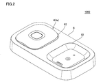
- FIG. 2 is a perspective view showing a state where the control device is set to the charging device in the charging system according to the present embodiment.
- charging system 1000 includes a control device 4 (housing 4 a) which is a main portion of an electrotherapy device, and a charging device 6 for charging control device 4.
- the electrotherapy device according to the present embodiment is a so-called cordless type low frequency therapy device.
- the control device 4 is equipped with a rechargeable secondary battery.
- the control device 4 (the housing 4 a) is fitted into and held by the concave holding portion 62 of the charging device 6.
- the lower member of the housing 4a and the holding portion 62 of the charging device 6 are fitted, and the housing 4a and the charging device 6 are held in close contact with each other.
- Non-contact charging is performed by mounting a coil on each of the charging device 6 on the power transmission side and the control device 4 on the power receiving side, and non-contactly transmitting power by electromagnetic induction between the coils.
- a member for example, a metal terminal
- the control device 4 can be easily held by the charging device 6, and short circuit due to mixing of dust, moisture, and the like in the member can be prevented.
- FIG. 3 is a plan view showing the pad and the holder of the electric therapeutic device according to the present embodiment.
- FIG. 4 is a perspective view showing a control device of the electrotherapy device according to the present embodiment.
- FIG. 5 is a plan view of a control device of the electrotherapy device according to the present embodiment.
- FIG. 6 is a side view seen from the arrow VI in FIG.
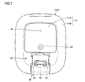
- FIG. 7 is a bottom view of the control device of the electrotherapy device according to the present embodiment.
- the electrotherapy device includes the pad 2 and the holder 3 shown in FIG. 3 and the control device 4 which is the main body shown in FIGS. 4 to 7.
- pad 2 has a sheet-like shape and is attached to the user's body.
- a conductive layer 2 a is provided on the surface (lower surface) of the body side 21 facing the body among the outer surfaces of the pad 2.
- the pad 2 is attached on the skin of the user using a conductive gel or the like, and a low frequency pulse current is supplied to the user through the conductive layer 2a.
- the pad 2 is held by the holder 3.
- a through hole 23 is provided in the pad 2, and the protruding terminal 33 of the holder 3 is inserted into the through hole 23.
- the treatment part 2Y of the pad 2 is provided on the left and right sides, and the conductive layer 2a is exposed on the body side 21 of the treatment part 2Y.
- the protruding terminals 33 of the holder 3 are formed for electrical connection with the terminal holes 43 (see FIG. 7) on the control device 4 side.
- a pulse current is supplied to the user through the conductive layer 2 a of the pad 2.
- the pad 2 is a consumable item, the pad 2 is removable from the control device 4 at the time of replacement.
- the holder 3 is integrated by holding the pad 2, and the control device 4 is attached to and detached from the pad 2 and the holder 3. Although the pad 2 is replaced with the holder 3, it is not impossible to reuse the holder 3 as needed.
- control device 4 includes, as an exterior body, a casing 4a having a substantially rectangular parallelepiped shape.
- the control device 4 (the housing 4 a) is detachably attached to the holder 3.
- the control device 4 supplies a low frequency pulse current to the conductive layer 2 a of the pad 2 in a state of being attached to the holder 3.
- the housing 4a is composed of an upper member 111 including an upper surface portion 110 and a side surface portion 112, and a lower member 114, as shown in FIGS.
- the upper member 111 and the lower member 114 are connected.
- the upper surface portion 110 has a substantially rectangular shape slightly curved toward the outside of the housing 4a.
- a power button 45 is integrally provided on the upper surface portion 110.
- the side surface portion 112 has a substantially annular shape.
- the side surface portion 112 is provided with a button 46 for attaching and detaching the holder 3 to and from the housing 4a.
- the lower member 114 is composed of a substantially rectangular flat bottom portion 114 a and a curved surface portion 114 b formed in a convex curved surface from the edge of the bottom portion 114 a.
- the curved surface portion 114 b together with the upper surface portion 110 and the side surface portion 112 realizes a three-dimensional shape of the control device 4.
- a substrate, an electric circuit, a secondary battery, a power receiving coil 54, and the like are provided in the control device 4 (the housing 4a).
- An electrical circuit is mounted on the surface of the substrate.
- the electric circuit includes a processor for executing various processes, a memory for storing programs and data, a communication interface for wirelessly communicating various data with an external device, boosting of power supply voltage, and low frequency pulse current (treatment current Waveform generation and output device for generating and outputting etc.).
- the control device 4 can charge the secondary battery using the power received by the power receiving coil 54.
- the bottom surface portion 114 a is provided with a positioning recess 52 for positioning the control device 4 with respect to the holding portion 62 of the charging device 6.
- the positioning recess 52 is fitted into the positioning protrusion provided in the holding portion 62, whereby the control device 4 is held by the holding portion 62.
- a terminal hole 43 for inserting the protruding terminal 33 of the holder 3 is provided inside the positioning recess 52.
- the terminal holes 43 are electrically connected to a substrate (electric circuit) inside the housing 4a.
- an LED 48 as a light emitting portion and a reset button 49 are provided in the bottom portion 114a.
- the LED 48 emits light in accordance with the instruction of the processor of the control device 4.
- the reset button 49 is a button for initializing the electrotherapy device 20. For example, when the electrotherapy device 20 receives pressing of the reset button 49, the electrotherapy device 20 deletes the pairing information and the like stored in the internal memory when being paired with the external device.
- FIG. 8 is a perspective view showing charging device 6 according to the present embodiment.
- FIG. 9 is a plan view of charging device 6 according to the present embodiment.
- the charging device 6 holds the control device 4 and charges the secondary battery accommodated in the control device 4.
- charging device 6 includes a support portion 61 and two holding portions 62 formed on the surface of support portion 61.
- the support portion 61 is a base that supports the control device 4 (the housing 4 a) held by the holding portion 62, and the holding portion 62 is formed on the substantially rectangular upper surface side.
- the two holding portions 62 are formed in the support portion 61, the two control devices 4 can be charged simultaneously by fitting the control devices 4 into the respective holding portions 62. it can.
- the number of holding portions 62 provided in the support portion 61 may be one.
- the holding portion 62 shows a portion for holding the control device 4, and is formed so as to be recessed in a shape corresponding to the shape of the lower member 114 of the housing 4 a. Specifically, the holding portion 62 has a concave shape for fitting the lower member 114. Further, as shown in FIG. 9, the shape of the outer edge of the holding portion 62 as viewed from the front is formed in a substantially rectangular shape.
- the holding portion 62 is composed of a flat portion 68 and a curved portion 66.
- the flat portion 68 faces the bottom surface portion 114 a of the lower member 114 held by the holding portion 62.
- the curved surface portion 66 is a concave curved surface and faces the curved surface portion 114 b of the lower member 114 held by the holding portion 62. That is, the holding portion 62 has a flat portion 68 corresponding to the shape of the bottom surface portion 114 a of the control device 4 and a curved surface portion 66 corresponding to the curved surface portion 114 b formed at the outer edge of the bottom surface portion 114 a.
- the flat portion 68 of the holding portion 62 is provided with a positioning convex portion 64 fitted to the positioning concave portion 52 of the control device 4 (the housing 4 a).
- the housing 4 a is held by the inner peripheral edge of the positioning recess 52 being fitted into the positioning protrusion 64.
- the light receiving element 70 is a light detector such as a photodiode.
- the light receiving element 70 is provided to face the LED 48 provided on the lower member 114 of the housing 4 a in a state where the control device 4 is held by the holding unit 62.
- a power transmission coil 72 for transmitting power to the power reception coil 54, a power supply connection terminal connected to an external power supply, and the like are provided inside the support portion 61 of the charging device 6, a power transmission coil 72 for transmitting power to the power reception coil 54, a power supply connection terminal connected to an external power supply, and the like are provided.
- the power transmission coil 72 is provided to face the power receiving coil 54 of the control device 4 in a state where the control device 4 (the housing 4 a) is held by the holding unit 62.
- a current flows through the transmission coil 72 to generate a magnetic field. Power can be generated in the receiving coil 54 of the control device 4 by the flow of the magnetic force.
- the electric circuit includes a processor, a memory, and the like that receives various electric signals received by the light receiving element 70 and performs various processes.
- FIG. 10 is a block diagram showing an example of a hardware configuration of a control device of the electrotherapy device according to the present embodiment.
- control device 4 includes, as main components, processor 210, memory 220, input interface (I / F) 230, secondary battery 240, charging circuit 250, and waveform generation and output device. 260, a receiving coil 54, and an LED 48.
- the processor 210 is typically an arithmetic processing unit such as a central processing unit (CPU) or a multi processing unit (MPU).
- the processor 210 functions as a control unit that controls the operation of each unit of the control device 4 by reading and executing the program stored in the memory 220.
- the processor 210 implements each of the processes (steps) of the control device 4 described later by executing the program.
- the memory 220 is realized by a random access memory (RAM), a read-only memory (ROM), or the like.
- the memory 220 stores programs executed by the processor 210, data used by the processor 210, and the like.
- the input interface 230 is various buttons for receiving an instruction from the user.
- the secondary battery 240 supplies power to each component of the control device 4.
- the secondary battery 240 is, for example, a lithium ion battery.
- the charging circuit 250 is connected to the power receiving coil 54 for charging, and uses the power derived from the power receiving coil 54 to charge the secondary battery 240.
- the waveform generation output device 260 outputs a current flowing through the pad 2 to a treatment site on the user's body.
- the waveform generation and output device 260 includes a booster circuit, a voltage adjustment circuit, an output circuit, a current detection circuit, and the like.
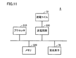
- FIG. 11 is a block diagram showing an example of a hardware configuration of the charging device according to the present embodiment.
- charging device 6 includes, as main components, processor 310 for executing various processes, memory 320 for storing various information, power transmission circuit 330, power transmission coil 72, and light receiving element 70. And.
- the light receiving element 70 converts the received light into an electrical signal, and inputs the electrical signal to the processor 310.
- the processor 310 controls the power transmission circuit 330 based on the electrical signal converted by the light receiving element 70.
- the power transmission circuit 330 supplies the AC power received from an external power source such as a household power source to the power transmission coil 72 according to the instruction of the processor 310.
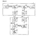
- FIG. 12 is a block diagram showing functional configurations of control device 4 and charging device 6 according to the present embodiment.
- control device 4 includes, as main functional components, detection unit 402, light emission control unit 404, light emission unit 406, and charge control unit 408.
- Charging device 6 includes, as main functional components, light receiving unit 450, authentication unit 452, information storage unit 454, and power transmission control unit 456.
- the detection unit 402 of the control device 4 detects the holding state of the control device 4 with respect to the holding unit 62 of the charging device 6. Specifically, in the detection unit 402, whether the positioning concave portion 52 of the control device 4 is fitted into the positioning convex portion 64 provided in the holding portion 62 of the charging device 6 (that is, the control device 4 is held To detect whether or not they are not fitted (that is, the state in which the control device 4 is not held).
- the detection unit 402 may mechanically detect that the positioning protrusion 64 has been fitted into the positioning recess 52 via a switch (not shown) provided in the positioning recess 52. Further, the detection unit 402 indicates that the positioning convex portion 64 is fitted into the positioning concave portion 52 based on a voltage change when the positioning convex portion 64 contacts a terminal (not shown) provided in the positioning concave portion 52. It may be detected.
- Information on the detection result of the detection unit 402 (for example, information indicating that the control device 4 is held in the holding unit 62) is supplied to the light emission control unit 404.
- the light emission control unit 404 causes the light emitting unit 406 to emit light when the control device 4 is fitted into the holding unit 62.
- the light from the light emitting unit 406 is used for the authentication process of the charging device 6. Specifically, when the control device 4 is fitted in the holding unit 62, the light emission control unit 404 causes the light emitting unit 406 to emit light at predetermined intervals (for example, every one second).
- the light emission control unit 404 stops the light emission from the light emitting unit 406 when the holding of the control device 4 to the holding unit 62 is released.
- the light emission control unit 404 is realized by the processor 210, for example.
- the light emitting unit 406 is realized by, for example, the LED 48.
- the light receiving unit 450 of the charging device 6 receives the light from the light emitting unit 406, converts the light into an electrical signal, and supplies the electrical signal to the authenticating unit 452.
- the light receiving unit 450 is realized by, for example, the light receiving element 70.
- the authentication unit 452 authenticates whether the light received by the light receiving unit 450 permits the power transmission to the control device 4. Specifically, the authentication unit 452 executes an authentication process of comparing and collating information based on the received light with predetermined reference information.
- the reference information is information indicating the definition of light indicating permission of power transmission, and is stored in the information storage unit 454 implemented by the memory 320.
- the reference information is information on light emitted by the LED 48 of the control device 4.
- Information on light may be information indicating wavelength characteristics of light, or information indicating transmission intensity of a specific wavelength.
- the authentication unit 452 compares the wavelength characteristic of the received light with the wavelength characteristic indicated by the reference information, and determines that the authentication is successful if they match.
- the authentication unit 452 compares the transmission intensity of the specific wavelength of the received light with the transmission intensity of the specific wavelength indicated by the reference information, and determines that the authentication is successful if they match. That is, when it is confirmed that the received light is the light emitted from the LED 48 mounted on the control device 4, the authentication unit 452 determines that the authentication is successful.
- the authentication unit 452 executes an authentication process each time light is received by the light receiving unit 450 (that is, each time light is emitted from the light emitting unit 406 at a predetermined interval).
- the authentication result of the authentication unit 452 is supplied to the power transmission control unit 456.
- the authentication unit 452 is realized by, for example, the processor 310.
- the power transmission control unit 456 causes the power transmission coil 72 to transmit power.
- the power transmission control unit 456 stops the power transmission of the power from the power transmission coil 72 when the authentication by the authentication unit 452 fails while the power is transmitted from the power transmission coil 72.
- the power transmission control unit 456 is realized by, for example, the processor 310 and the power transmission circuit 330.
- the charge control unit 408 of the control device 4 receives the power from the power transmission coil 72 via the power reception coil 54, and supplies the power to the secondary battery 240.
- the charge control unit 408 is configured to be able to detect the remaining amount of the secondary battery 240. Since the output voltage or output current of the secondary battery decreases in accordance with the remaining battery charge, the charge control unit 408 detects the remaining battery charge based on the output voltage or output current.
- the charge control unit 408 supplies information indicating the completion of charging to the light emission control unit 404 when the charging of the secondary battery 240 is completed (that is, when the battery remaining amount is 100% and the battery is fully charged). Do. When the charging of the secondary battery 240 is completed, the light emission control unit 404 stops the emission of light by the light emitting unit 406.
- FIG. 13 is a flowchart showing an example of the processing procedure of the control device and the charging device according to the present embodiment. For example, each step of the following control device 4 is performed by the processor 210, and each step of the charging device 6 is performed by the processor 310. The following processing is repeated at predetermined intervals (control cycles).
- control device 4 determines whether or not housing 4 a is held by holding unit 62 of charging device 6 (step S ⁇ b> 10). Specifically, the control device 4 determines whether the positioning recess 52 is fitted into the positioning protrusion 64 or not.
- control device 4 determines whether or not secondary battery 240 is in a fully charged state (that is, a charging completed state) (step S12). If the secondary battery 240 is not fully charged (NO in step S12), the control device 4 causes the LED 48 to emit light (step S14).
- control device 4 ends the process.
- the LED 48 does not emit light.
- control device 4 ends the process. Also in this case, the LED 48 does not emit light. That is, even when the case 4a is held by the holding portion 62, the control device 4 does not emit light from the LED 48 when the secondary battery 240 is fully charged (the light from the LED 48 Stop the light emission).
- the charging device 6 determines whether light is received through the light receiving element 70 (step S16). If the charging device 6 does not receive light (NO in step S16), the charging device 6 executes the process of step S24, which is vertical. On the other hand, when the charging device 6 receives the light (YES in step S16), the charging device 6 determines whether the authentication process has succeeded based on the received light (step S18). Specifically, the charging device 6 performs an authentication process for permitting power transmission to the control device 4 by comparing and collating information based on the received light with reference information, and performs the determination.
- step S18 If the authentication is successful (YES in step S18), the charging device 6 transmits power from the power transmission coil 72 (step S20). At this time, when power is being transmitted from the power transmission coil 72, the power transmission is maintained. The control device 4 receives power via the power receiving coil 54 (step S22), and ends the process.
- step S24 determines whether power transmission from the power transmission coil 72 is being performed. If power transmission is being performed (YES in step S24), the charging device 6 stops power transmission from the power transmission coil 72 (step S26), and ends the process. On the other hand, when power transmission is not being performed (NO in step S24), charging device 6 ends the process. In this case, the power transmission coil 72 does not start power transmission.
- ⁇ Advantage> when the control device 4 is held by the holding portion 62, extraneous external light reaching the light receiving element 70 is blocked, and the LED 48 and the light receiving element 70 are disposed at a position facing each other. Ru. Since the detection sensitivity of the light from the LED 48 is improved by the light receiving element 70, highly accurate authentication processing can be performed.
- the charging is automatically started only by the operation of fitting the control device 4 into the holding portion 62, so the convenience for the user is improved.
- the authentication process is performed at predetermined intervals, and power transmission is stopped when the authentication fails.
- security is also improved by performing authentication constantly.
- the controller 4 of the electrotherapy device may be configured not to communicate with an external device or the like when being held by the holder 62 of the charging device 6. It may be configured not to output the treatment current.
- the arrangement of the LED 48 and the light receiving element 70 is not limited to the above, and the light receiving element 70 and the LED 48 are arranged to face each other when the control device 4 is held by the holding unit 62. It should just be.
- a program that causes a computer to function to execute control as described in the above-described flowchart.
- a program is recorded on a non-temporary computer readable recording medium such as a flexible disk attached to a computer, a CD (Compact Disk Read Only Memory), a secondary storage device, a main storage device, and a memory card. It can also be provided as a program product.
- the program can be provided by being recorded in a recording medium such as a hard disk built in the computer.
- the program can be provided by downloading via a network.
- the program may call a required module among program modules provided as a part of an operating system (OS) of a computer in a predetermined arrangement at a predetermined timing to execute processing.
- OS operating system
- the program itself does not include the above module, and the processing is executed in cooperation with the OS.
- a program that does not include such a module may also be included in the program according to the present embodiment.
- the program according to the present embodiment may be provided by being incorporated into a part of another program. Also in this case, the program itself does not include a module included in the other program, and the process is executed in cooperation with the other program. Programs incorporated into such other programs may also be included in the program according to the present embodiment.
- the configuration exemplified as the above-described embodiment is an example of the configuration of the present invention, and can be combined with another known technique, and a part of the configuration can be made without departing from the scope of the present invention. It is also possible to change and configure, such as omitting. Moreover, in the embodiment described above, the processing and configuration described in the other embodiments may be appropriately adopted and implemented.
Abstract
充電システムは、電気治療器の制御装置(4)と、制御装置(4)を非接触で充電する充電装置(6)とを備える。充電装置(6)は、支持部と、支持部に形成された、制御装置(4)を嵌め込むための凹形状の保持部とを含む。制御装置(4)は、保持部に制御装置(4)が嵌め込まれた場合に、光を発光する発光部(406)を含む。充電装置(6)は、発光部(406)からの光を受光する受光部(450)と、受光された光に基づく第1情報と、予め定められた第2情報とを比較照合する認証処理を実行する認証部(452)と、電力を送電するための送電コイル(72)と、認証部による認証が成功した場合に、送電コイルから電力を送電する送電制御部(456)とを含む。制御装置(4)は、送電コイル(72)からの電力を受電する受電コイル(54)と、受電コイル(54)により受電した電力により充電される二次電池(240)とを含む。
Description
本開示は、電気治療器の制御装置を非接触で充電するための技術に関する。
近年、携帯電話等の小型の電子機器に対して、非接触(ワイヤレス)で給電する非接触充電システムが採用されている。小型の電子機器に内蔵された二次電池を充電するために、非接触充電システムを採用すれば、充電操作の煩雑さが大幅に改善される。
例えば、特表2015-507468号公報(特許文献1)は、携帯デバイスのようなポータブル電子機器をワイヤレスで充電する方法および装置を開示している。
ところで、肩凝りをほぐす等の治療を行なう電気治療器(例えば、低周波治療器)は、本体部として各種処理を制御する制御装置、および取り外し可能なパッド等から構成されている。制御装置は、電源としての二次電池を搭載しており、比較的小型のものが多く、充電操作の煩雑さを改善するため、当該二次電池を非接触で充電したいというニーズがある。また、制御装置の模造品等が勝手に充電されないようにしたいという要求も高まっている。
本開示は、ある局面では、充電装置に保持された電気治療器の制御装置を、簡易かつ適切に非接触で充電することが可能な充電システムを提供することを目的とする。また、本開示は、他の局面では、このような充電システムに用いられる充電装置、および電気治療器の制御装置を提供することを目的とする。
ある実施の形態に従うと、電気治療器の制御装置と、制御装置を非接触で充電する充電装置とを備える充電システムが提供される。充電装置は、支持部と、支持部に形成された、制御装置を嵌め込むための凹形状の保持部とを含む。制御装置は、保持部に制御装置が嵌め込まれた場合に、光を発光する発光部を含む。充電装置は、発光部からの光を受光する受光部と、受光された光に基づく第1情報と、予め定められた第2情報とを比較照合する認証処理を実行する認証部と、電力を送電するための送電コイルと、認証部による認証が成功した場合に、送電コイルから電力を送電する送電制御部とをさらに含む。制御装置は、送電コイルからの電力を受電する受電コイルと、受電コイルにより受電した電力により充電される二次電池とをさらに含む。
好ましくは、保持部は、制御装置の底面の形状に対応した平坦部と、制御装置の底面の外縁に形成されている曲面形状に対応した曲面部とを含む。
好ましくは、制御装置の底面には、位置決め凹部が設けられており、保持部における平坦部には、位置決め凹部に嵌合される位置決め凸部が設けられている。
好ましくは、保持部に制御装置が嵌め込まれている場合、発光部は、予め定められた間隔で光を発光する。認証部は、受光部により光が受光されるごとに認証処理を実行する。
好ましくは、送電制御部は、送電コイルから電力を送電しているときに認証部による認証が失敗した場合、送電コイルからの電力の送電を停止させる。
好ましくは、発光部は、二次電池の充電が完了した場合、光の発光を停止する。
好ましくは、電気治療器は、低周波治療器である。
好ましくは、電気治療器は、低周波治療器である。
別の実施の形態に従うと、電気治療器の制御装置を非接触で充電するための充電装置が提供される。充電装置は、支持部と、支持部に形成された、制御装置を嵌め込むための凹形状の保持部と、保持部に制御装置が嵌め込まれた場合に、制御装置から発光された光を受光する受光部と、受光された光に基づく第1情報と、予め定められた第2情報とを比較照合する認証処理を実行する認証部と、電力を送電するための送電コイルと、認証部による認証が成功した場合に、送電コイルから制御装置に含まれる受電コイルに電力を送電する送電制御部とを備える。
さらに他の実施の形態に従うと、充電装置からの電力により非接触で充電される電気治療器の制御装置が提供される。制御装置は、充電装置の支持部に形成された凹形状の保持部に制御装置が嵌め込まれた場合に、光を発光する発光部と、充電装置の受光部により受光された光に基づく第1情報と、予め定められた第2情報とを比較照合する認証処理が成功した場合に充電装置の送電コイルから送電される電力を受電する受電コイルと、受電コイルにより受電した電力により充電される二次電池とを備える。
本開示によると、充電装置に保持された電気治療器の制御装置を、簡易かつ適切に非接触で充電することが可能となる。
以下、図面を参照しつつ、本発明の実施の形態について説明する。以下の説明では、同一の部品には同一の符号を付してある。それらの名称および機能も同じである。したがって、それらについての詳細な説明は繰り返さない。
<概略構成>
本実施の形態に従う充電システムの概略構成について説明する。図1は、本実施形態に従う充電システムにおいて、制御装置と充電装置とを分離した状態を示す斜視図である。図2は、本実施の形態に従う充電システムにおいて、制御装置を充電装置にセットした状態を示す斜視図である。
本実施の形態に従う充電システムの概略構成について説明する。図1は、本実施形態に従う充電システムにおいて、制御装置と充電装置とを分離した状態を示す斜視図である。図2は、本実施の形態に従う充電システムにおいて、制御装置を充電装置にセットした状態を示す斜視図である。
図1および図2を参照して、充電システム1000は、電気治療器の本体部である制御装置4(筐体4a)と、制御装置4を充電するための充電装置6とを含む。本実施の形態に従う電気治療器は、いわゆるコードレスタイプの低周波治療器である。
制御装置4は、充電可能な二次電池を搭載している。二次電池を充電する場合には、図2に示すように、制御装置4(筐体4a)を充電装置6における凹形状の保持部62に嵌め込んで保持させる。具体的には、筐体4aの下部材と、充電装置6の保持部62とが嵌合されて、筐体4aおよび充電装置6の相対向する面が密接した状態で保持される。
制御装置4に搭載される二次電池は、非接触充電(ワイヤレス充電)により充電される。非接触充電は、送電側である充電装置6および受電側である制御装置4にそれぞれコイルを搭載し、コイル間の電磁誘導で電力を非接触で伝送することにより行われる。
したがって、二次電池を充電する際に、制御装置4と充電装置6とを電気的に接続するための部材(例えば、金属端子)が不要となる。また、制御装置4を充電装置6に保持させ易く、上記部材に埃、水分等が混入することによるショートを防止することもできる。
<電気治療器の構成>
図3は、本実施の形態に従う電気治療器のパッドおよびホルダを示す平面図である。図4は、本実施の形態に従う電気治療器の制御装置を示す斜視図である。図5は、本実施の形態に従う電気治療器の制御装置の平面図である。図6は、図4中の矢印VIからみた側面図である。図7は、本実施の形態に従う電気治療器の制御装置の底面図である。
図3は、本実施の形態に従う電気治療器のパッドおよびホルダを示す平面図である。図4は、本実施の形態に従う電気治療器の制御装置を示す斜視図である。図5は、本実施の形態に従う電気治療器の制御装置の平面図である。図6は、図4中の矢印VIからみた側面図である。図7は、本実施の形態に従う電気治療器の制御装置の底面図である。
本実施の形態に従う電気治療器は、図3に示されるパッド2およびホルダ3と、図4~図7に示される本体部である制御装置4とを含む。
図3を参照して、パッド2は、シート状の形状を有し、ユーザの身体に取り付けられる。パッド2の外表面のうち、身体に対向する身体側部21の表面(下面)には、導電層2aが設けられる。パッド2は、導電性のゲル等を使用してユーザの皮膚上に貼り付けられ、導電層2aを通してユーザに低周波パルス電流が供給される。
パッド2は、ホルダ3によって保持される。パッド2には貫通孔23が設けられており、貫通孔23には、ホルダ3の突起状端子33が挿通される。パッド2の治療部2Yは、左右両外側に設けられ、治療部2Yの身体側部21には導電層2aが露出している。
ホルダ3の突起状端子33は、制御装置4側の端子穴43(図7参照)との電気的接続のために形成されている。突起状端子33が、制御装置4側の端子穴43に挿入されると(接続されると)、パッド2の導電層2aを通してユーザにパルス電流が供給される。
パッド2は消耗品であるので、交換の際には、パッド2は制御装置4に対して着脱可能とされている。本実施の形態では、ホルダ3がパッド2を保持することで両者が一体となっており、パッド2およびホルダ3に対して制御装置4を着脱するよう構成されている。パッド2はホルダ3ごと交換されるが、必要に応じてホルダ3を再利用することも不可能ではない。
図4~図7を参照して、制御装置4は、略直方体の形状を有する筐体4aを外装体として含んでいる。制御装置4(筐体4a)は、ホルダ3に着脱可能に取り付けられる。制御装置4は、ホルダ3に取り付けられた状態で、パッド2の導電層2aに低周波パルス電流を供給する。
筐体4aは、図4~図7に示すように、上面部110と側面部112とを含む上側部材111と、下部材114とから構成される。上側部材111と下部材114とは連結されている。上面部110は、筐体4a外部に向かって僅かに湾曲する略長方形状を有する。上面部110には、電源ボタン45が一体に設けられている。側面部112は、略環形状を有する。側面部112には、筐体4aに対してホルダ3を着脱するためのボタン46が設けられている。
下部材114は、略長方形状の平坦な底面部114aと、底面部114aの縁部から凸状の曲面に形成される曲面部114bとから構成される。曲面部114bは、上面部110および側面部112とともに制御装置4の立体的な形状を実現する。
制御装置4(筐体4a)の内部には、基板、電気回路、二次電池、受電コイル54等が設けられている。電気回路は、基板の表面上に実装されている。電気回路は、各種処理を実行するためのプロセッサ、プログラムやデータなどを格納するためのメモリ、外部装置と各種データを無線通信するための通信インターフェイス、電源電圧の昇圧、低周波パルス電流(治療電流)の生成および出力等を行なうための波形生成出力装置等を含む。
充電装置6に設けられた送電コイル(後述する図8中の送電コイル72)と受電コイル54とを対向させた状態で送電コイルに電流を流すと、電磁誘導により送電コイルから受電コイル54に電力が伝送される。制御装置4は、受電コイル54により受電された電力を利用して、二次電池を充電することができる。
底面部114aには、充電装置6の保持部62に対して制御装置4を位置決めするための位置決め凹部52が設けられている。位置決め凹部52が、保持部62に設けられた位置決め凸部に嵌め込まれることにより、保持部62に制御装置4が保持される。また、位置決め凹部52の内部には、ホルダ3の突起状端子33を挿入するための端子穴43が設けられている。端子穴43は、筐体4a内部の基板(電気回路)と電気的に接続されている。
また、底面部114aには、発光部としてのLED48と、リセットボタン49とが設けられている。LED48は、制御装置4のプロセッサの指示に従って発光する。リセットボタン49は、電気治療器20を初期化するためのボタンである。例えば、電気治療器20は、リセットボタン49の押下を受け付けると、外部装置とペアリング接続されたときに内部メモリに格納されたペアリング情報等を削除する。
<充電装置の構成>
図8は、本実施の形態に従う充電装置6を示す斜視図である。図9は、本実施の形態に従う充電装置6の平面図である。充電装置6は、制御装置4を保持し、制御装置4に収容された二次電池を充電する。図8および図9を参照して、充電装置6は、支持部61と、支持部61の表面に形成された2つの保持部62とを含む。
図8は、本実施の形態に従う充電装置6を示す斜視図である。図9は、本実施の形態に従う充電装置6の平面図である。充電装置6は、制御装置4を保持し、制御装置4に収容された二次電池を充電する。図8および図9を参照して、充電装置6は、支持部61と、支持部61の表面に形成された2つの保持部62とを含む。
支持部61は、保持部62により保持された制御装置4(筐体4a)を支持する基台であり、略長方形状の上面側に保持部62が形成されている。本実施の形態では、支持部61には、2つの保持部62が形成されているため、各保持部62に各制御装置4を嵌め込むことにより、2つの制御装置4を同時に充電することができる。ただし、支持部61に設けられる保持部62が1つであってもよい。
保持部62は、制御装置4を保持する部分を示しており、筐体4aの下部材114の形状に対応した形状に陥没して形成されている。具体的には、保持部62は、下部材114を嵌め込むための凹形状を有している。また、図9に示すように、保持部62は正面から見た外縁の形状が略長方形状に形成されている。
保持部62は、平坦部68と、曲面部66とから構成される。平坦部68は、保持部62に保持された下部材114の底面部114aと対向する。曲面部66は、凹状の曲面であり、保持部62に保持された下部材114の曲面部114bと対向する。すなわち、保持部62は、制御装置4の底面部114aの形状に対応した平坦部68と、底面部114aの外縁に形成されている曲面部114bに対応した曲面部66とを有する。
保持部62の平坦部68には、制御装置4(筐体4a)の位置決め凹部52に嵌合される位置決め凸部64が設けられている。位置決め凹部52の内周縁が位置決め凸部64に嵌め込まれることにより、筐体4aが保持される。
受光素子70は、フォトダイオード等の光検出器である。受光素子70は、制御装置4が保持部62に保持された状態において、筐体4aの下部材114に設けられたLED48と対向するように設けられる。
充電装置6の支持部61の内部には、受電コイル54に電力を送電するための送電コイル72、外部電源と接続される電源接続端子等が設けられる。送電コイル72は、制御装置4(筐体4a)が保持部62に保持された状態において、制御装置4の受電コイル54と対向するように設けられる。外部電源と接続されて電源接続端子を介して電流が入力されると、送電コイル72に電流が流れて磁界が発生する。その磁力の流れによって制御装置4の受電コイル54に電力を生じさせることができる。
また、支持部61の内部には、基板(図示しない)、電気回路(図示しない)がさらに設けられる。電気回路は、受光素子70により変換された電気信号の入力を受け付けて各種処理を実行するプロセッサ、メモリ等を含む。
<ハードウェア構成>
(電気治療器の制御装置)
図10は、本実施の形態に従う電気治療器の制御装置のハードウェア構成の一例を表わすブロック図である。図10を参照して、制御装置4は、主たる構成要素として、プロセッサ210と、メモリ220と、入力インターフェイス(I/F)230と、二次電池240と、充電回路250と、波形生成出力装置260と、受電コイル54と、LED48とを含む。
(電気治療器の制御装置)
図10は、本実施の形態に従う電気治療器の制御装置のハードウェア構成の一例を表わすブロック図である。図10を参照して、制御装置4は、主たる構成要素として、プロセッサ210と、メモリ220と、入力インターフェイス(I/F)230と、二次電池240と、充電回路250と、波形生成出力装置260と、受電コイル54と、LED48とを含む。
プロセッサ210は、典型的には、CPU(Central Processing Unit)やMPU(Multi Processing Unit)といった演算処理部である。プロセッサ210は、メモリ220に記憶されたプログラムを読み出して実行することで、制御装置4の各部の動作を制御する制御部として機能する。プロセッサ210は、当該プログラムを実行することによって、後述する制御装置4の処理(ステップ)の各々を実現する。
メモリ220は、RAM(Random Access Memory)、ROM(Read-Only Memory)等によって実現される。メモリ220は、プロセッサ210によって実行されるプログラム、またはプロセッサ210によって用いられるデータなどを記憶する。入力インターフェイス230は、ユーザからの指示を受け付けるための各種ボタンである。
二次電池240は、制御装置4の各構成要素に電力を供給する。二次電池240は、例えば、リチウムイオン電池である。充電回路250は、充電のための受電コイル54と接続され、受電コイル54から導出される電力を用いて、二次電池240を充電する。
波形生成出力装置260は、パッド2を介してユーザの身体の治療部位に流れる電流を出力する。波形生成出力装置260は、昇圧回路、電圧調整回路、出力回路、電流検出回路等を含む。
(充電装置)
図11は、本実施の形態に従う充電装置のハードウェア構成の一例を表わすブロック図である。図11を参照して、充電装置6は、主たる構成要素として、各種処理を実行するためのプロセッサ310と、各種情報を記憶するメモリ320と、送電回路330と、送電コイル72と、受光素子70とを含む。
図11は、本実施の形態に従う充電装置のハードウェア構成の一例を表わすブロック図である。図11を参照して、充電装置6は、主たる構成要素として、各種処理を実行するためのプロセッサ310と、各種情報を記憶するメモリ320と、送電回路330と、送電コイル72と、受光素子70とを含む。
受光素子70は、受光した光を電気信号に変換して、当該電気信号をプロセッサ310に入力する。プロセッサ310は、受光素子70により変換された電気信号に基づいて、送電回路330を制御する。送電回路330は、プロセッサ310の指示に従って、家庭用電源等の外部電源から受けた交流電力を送電コイル72に供給する。
<機能構成>
図12は、本実施の形態に従う制御装置4および充電装置6の機能構成を示すブロック図である。図12を参照して、制御装置4は、主な機能構成として、検出部402と、発光制御部404と、発光部406と、充電制御部408とを含む。充電装置6は、主な機能構成として、受光部450と、認証部452と、情報格納部454と、送電制御部456とを含む。
図12は、本実施の形態に従う制御装置4および充電装置6の機能構成を示すブロック図である。図12を参照して、制御装置4は、主な機能構成として、検出部402と、発光制御部404と、発光部406と、充電制御部408とを含む。充電装置6は、主な機能構成として、受光部450と、認証部452と、情報格納部454と、送電制御部456とを含む。
制御装置4の検出部402は、充電装置6の保持部62に対する制御装置4の保持状態を検出する。具体的には、検出部402は、制御装置4の位置決め凹部52が、充電装置6の保持部62に設けられた位置決め凸部64へ嵌め込まれているのか(すなわち、制御装置4が保持されている状態)、嵌め込まれていないのか(すなわち、制御装置4が保持されていない状態)を検出する。
例えば、検出部402は、位置決め凹部52に設けられたスイッチ(図示しない)を介して、位置決め凸部64が位置決め凹部52に嵌め込められたことを機械的に検出してもよい。また、検出部402は、位置決め凹部52に設けられた端子(図示しない)に位置決め凸部64が接触したときの電圧変化に基づいて、位置決め凸部64が位置決め凹部52に嵌め込められたことを検出してもよい。
検出部402による検出結果の情報(例えば、制御装置4が保持部62に保持されていることを示す情報)は、発光制御部404に供給される。
発光制御部404は、保持部62に制御装置4が嵌め込まれた場合に、発光部406から光を発光させる。発光部406からの光は、充電装置6の認証処理に用いられる。具体的には、発光制御部404は、保持部62に制御装置4が嵌め込まれている場合には、予め定められた間隔で(例えば、1秒ごとに)発光部406から光を発光させる。発光制御部404は、保持部62に対する制御装置4の保持が解除された場合には、発光部406からの光の発光を停止させる。発光制御部404は、例えば、プロセッサ210により実現される。発光部406は、例えば、LED48により実現される。
充電装置6の受光部450は、発光部406からの光を受光し、当該光を電気信号に変換し、当該電気信号を認証部452に供給する。受光部450は、例えば、受光素子70によって実現される。
認証部452は、受光部450によって受光される光が制御装置4への送電を許可するものであるか否かを認証する。具体的には、認証部452は、受光された光に基づく情報と、予め定められた基準情報とを比較照合する認証処理を実行する。基準情報は、送電を許可することを示す光の定義を示す情報であり、メモリ320により実現される情報格納部454に格納される。例えば、基準情報は、制御装置4のLED48が発光する光に関する情報である。光に関する情報は、光の波長特性を示す情報であってもよいし、特定波長の透過強度を示す情報であってもよい。
例えば、認証部452は、受光された光の波長特性と、基準情報が示す波長特性とを比較照合して、これらが一致した場合には認証が成功したと判断する。また、認証部452は、受光された光の特定波長の透過強度と、基準情報が示す特定波長の透過強度とを比較照合して、これらが一致した場合には認証が成功したと判断する。すなわち、認証部452は、受光した光が、制御装置4に搭載されたLED48が発光した光であることを確認できた場合に、認証が成功したと判断する。
認証部452は、受光部450により光が受光されるごと(すなわち、発光部406から予め定められた間隔で光が発光されるごと)に認証処理を実行する。認証部452の認証結果は、送電制御部456に供給される。認証部452は、例えば、プロセッサ310により実現される。
送電制御部456は、認証部452による認証が成功した場合に、送電コイル72から電力を送電させる。他の局面では、送電制御部456は、送電コイル72から電力が送電されているときに、認証部452による認証が失敗した場合、送電コイル72からの電力の送電を停止させる。送電制御部456は、例えば、プロセッサ310および送電回路330により実現される。
制御装置4の充電制御部408は、受電コイル54を介して、送電コイル72からの電力を受電し、当該電力を二次電池240に供給する。また、充電制御部408は、二次電池240の電池残量を検出可能に構成される。二次電池の出力電圧または出力電流は、電池残量に応じて減少するため、充電制御部408は、出力電圧または出力電流に基づいて電池残量を検出する。充電制御部408は、二次電池240の充電が完了した場合(すなわち、電池残量が100%であり、満充電状態である場合)には、充電完了を示す情報を発光制御部404に供給する。発光制御部404は、二次電池240の充電が完了した場合、発光部406による光の発光を停止させる。
<処理手順>
図13は、本実施の形態に従う制御装置および充電装置の処理手順の一例を示すフローチャートである。例えば、以下の制御装置4の各ステップはプロセッサ210により実行され、充電装置6の各ステップはプロセッサ310により実行される。以下の処理は、予め定められた間隔(制御周期)で繰り返される。
図13は、本実施の形態に従う制御装置および充電装置の処理手順の一例を示すフローチャートである。例えば、以下の制御装置4の各ステップはプロセッサ210により実行され、充電装置6の各ステップはプロセッサ310により実行される。以下の処理は、予め定められた間隔(制御周期)で繰り返される。
図13を参照して、制御装置4は、筐体4aが充電装置6の保持部62に保持されているか否かを判断する(ステップS10)。具体的には、制御装置4は、位置決め凹部52が、位置決め凸部64へ嵌め込まれているか否かを判断する。
筐体4aが保持部62に保持されている場合には(ステップS10においてYES)、制御装置4は、二次電池240が満充電状態(すなわち、充電完了状態)か否かを判断する(ステップS12)。二次電池240が満充電状態ではない場合には(ステップS12においてNO)、制御装置4は、LED48から光を発光させる(ステップS14)。
一方、筐体4aが保持部62に保持されていない場合には(ステップS10においてNO)、制御装置4は処理を終了する。この場合、LED48は発光しない。また、二次電池240が満充電状態である場合には(ステップS12においてYES)、制御装置4は処理を終了する。この場合も、LED48は発光しない。すなわち、制御装置4は、筐体4aが保持部62に保持されている場合であっても、二次電池240が満充電状態である場合にはLED48から光を発光させない(LED48からの光の発光を停止する)。
充電装置6は、受光素子70を介して、光を受光したか否かを判断する(ステップS16)。充電装置6は、光を受光していない場合には(ステップS16においてNO)、後縦するステップS24の処理を実行する。一方、充電装置6は、光を受光した場合には(ステップS16においてYES)、当該受光された光に基づいて、認証処理が成功したか否かを判断する(ステップS18)。具体的には、充電装置6は、受光された光に基づく情報と、基準情報とを比較照合することにより制御装置4への送電を許可するための認証処理を実行し、当該判断を行なう。
認証が成功した場合には(ステップS18においてYES)、充電装置6は、送電コイル72から電力を送電する(ステップS20)。このとき、送電コイル72から電力を送電中である場合には、当該送電が維持される。制御装置4は、受電コイル54を介して、電力を受電して(ステップS22)、処理を終了する。
認証が失敗した場合には(ステップS18においてNO)、充電装置6は、送電コイル72から電力の送電を実行しているか否かを判断する(ステップS24)。送電を実行中である場合(ステップS24においてYES)、充電装置6は、送電コイル72からの送電を停止して(ステップS26)、処理を終了する。一方、送電を実行中ではない場合には(ステップS24においてNO)、充電装置6は処理を終了する。この場合、送電コイル72は、送電を開始しない。
<利点>
本実施の形態によると、制御装置4が保持部62に保持された状態では、受光素子70に到達する余計な外光が遮断され、かつ、LED48と受光素子70とが対向する位置に配置される。受光素子70により、LED48からの光の検出感度が向上するため、精度の高い認証処理を実行することができる。
本実施の形態によると、制御装置4が保持部62に保持された状態では、受光素子70に到達する余計な外光が遮断され、かつ、LED48と受光素子70とが対向する位置に配置される。受光素子70により、LED48からの光の検出感度が向上するため、精度の高い認証処理を実行することができる。
本実施の形態によると、制御装置4を保持部62に嵌め込む操作だけで自動的に充電が開始されるため、ユーザの利便性が向上する。
本実施の形態によると、予め定められた間隔で認証処理が実行され、認証が失敗した場合には送電が停止される。このように、常時、認証を実行することによりセキュリティも向上する。
<その他の実施の形態>
(1)上述した実施の形態において、電気治療器の制御装置4は、充電装置6の保持部62に保持されている状態のときには、外部装置等と通信しないように構成されていてもよく、治療電流を出力しないように構成されていてもよい。
(1)上述した実施の形態において、電気治療器の制御装置4は、充電装置6の保持部62に保持されている状態のときには、外部装置等と通信しないように構成されていてもよく、治療電流を出力しないように構成されていてもよい。
(2)上述した実施の形態において、LED48および受光素子70の配置は上記に限られず、制御装置4が保持部62に保持された状態において、受光素子70とLED48とが対向するように配置されていればよい。
(3)上述した実施の形態において、コンピュータを機能させて、上述のフローチャートで説明したような制御を実行させるプログラムを提供することもできる。このようなプログラムは、コンピュータに付属するフレキシブルディスク、CD(Compact Disk Read Only Memory)、二次記憶装置、主記憶装置およびメモリカードなどの一時的でないコンピュータ読取り可能な記録媒体にて記録させて、プログラム製品として提供することもできる。あるいは、コンピュータに内蔵するハードディスクなどの記録媒体にて記録させて、プログラムを提供することもできる。また、ネットワークを介したダウンロードによって、プログラムを提供することもできる。
プログラムは、コンピュータのオペレーティングシステム(OS)の一部として提供されるプログラムモジュールのうち、必要なモジュールを所定の配列で所定のタイミングで呼出して処理を実行させるものであってもよい。その場合、プログラム自体には上記モジュールが含まれずOSと協働して処理が実行される。このようなモジュールを含まないプログラムも、本実施の形態にかかるプログラムに含まれ得る。
また、本実施の形態にかかるプログラムは他のプログラムの一部に組込まれて提供されるものであってもよい。その場合にも、プログラム自体には上記他のプログラムに含まれるモジュールが含まれず、他のプログラムと協働して処理が実行される。このような他のプログラムに組込まれたプログラムも、本実施の形態にかかるプログラムに含まれ得る。
(4)上述の実施の形態として例示した構成は、本発明の構成の一例であり、別の公知の技術と組み合わせることも可能であるし、本発明の要旨を逸脱しない範囲で、一部を省略する等、変更して構成することも可能である。また、上述した実施の形態において、その他の実施の形態で説明した処理や構成を適宜採用して実施する場合であってもよい。
今回開示された実施の形態はすべての点で例示であって制限的なものではないと考えられるべきである。本発明の範囲は、上記した説明ではなく、請求の範囲によって示され、請求の範囲と均等の意味および範囲内でのすべての変更が含まれることが意図される。
2 パッド、2Y 治療部、2a 導電層、3 ホルダ、4 制御装置、4a 筐体、6 充電装置、20 電気治療器、21 身体側部、23 貫通孔、33 突起状端子、43 端子穴、45 電源ボタン、46 ボタン、49 リセットボタン、52 位置決め凹部、54 受電コイル、61 支持部、62 保持部、64 位置決め凸部、66,114b 曲面部、68 平坦部、70 受光素子、72 送電コイル、110 上面部、111 上側部材、112 側面部、114 下部材、114a 底面部、210,310 プロセッサ、220,320 メモリ、230 入力インターフェイス、240 二次電池、250 充電回路、260 波形生成出力装置、330 送電回路、402 検出部、404 発光制御部、406 発光部、408 充電制御部、450 受光部、452 認証部、454 情報格納部、456 送電制御部、1000 充電システム。
Claims (9)
- 電気治療器の制御装置と、前記制御装置を非接触で充電する充電装置とを備える充電システムであって、
前記充電装置は、支持部と、前記支持部に形成された、前記制御装置を嵌め込むための凹形状の保持部とを含み、
前記制御装置は、前記保持部に前記制御装置が嵌め込まれた場合に、光を発光する発光部を含み、
前記充電装置は、
前記発光部からの光を受光する受光部と、
前記受光された光に基づく第1情報と、予め定められた第2情報とを比較照合する認証処理を実行する認証部と、
電力を送電するための送電コイルと、
前記認証部による認証が成功した場合に、前記送電コイルから電力を送電する送電制御部とをさらに含み、
前記制御装置は、
前記送電コイルからの電力を受電する受電コイルと、
前記受電コイルにより受電した電力により充電される二次電池とをさらに含む、充電システム。 - 前記保持部は、前記制御装置の底面の形状に対応した平坦部と、前記制御装置の底面の外縁に形成されている曲面形状に対応した曲面部とを含む、請求項1に記載の充電システム。
- 前記制御装置の底面には、位置決め凹部が設けられており、
前記保持部における前記平坦部には、前記位置決め凹部に嵌合される位置決め凸部が設けられている、請求項2に記載の充電システム。 - 前記保持部に前記制御装置が嵌め込まれている場合、前記発光部は、予め定められた間隔で光を発光し、
前記認証部は、前記受光部により光が受光されるごとに前記認証処理を実行する、請求項1~3のいずれか1項に記載の充電システム。 - 前記送電制御部は、前記送電コイルから電力を送電しているときに前記認証部による認証が失敗した場合、前記送電コイルからの電力の送電を停止させる、請求項4に記載の充電システム。
- 前記発光部は、前記二次電池の充電が完了した場合、光の発光を停止する、請求項1~5のいずれか1項に記載の充電システム。
- 前記電気治療器は、低周波治療器である、請求項1~6のいずれか1項に記載の充電システム。
- 電気治療器の制御装置を非接触で充電するための充電装置であって、
支持部と、
前記支持部に形成された、前記制御装置を嵌め込むための凹形状の保持部と、
前記保持部に前記制御装置が嵌め込まれた場合に、前記制御装置から発光された光を受光する受光部と、
前記受光された光に基づく第1情報と、予め定められた第2情報とを比較照合する認証処理を実行する認証部と、
電力を送電するための送電コイルと、
前記認証部による認証が成功した場合に、前記送電コイルから前記制御装置に含まれる受電コイルに電力を送電する送電制御部とを備える、充電装置。 - 充電装置からの電力により非接触で充電される電気治療器の制御装置であって、
前記充電装置の支持部に形成された凹形状の保持部に前記制御装置が嵌め込まれた場合に、光を発光する発光部と、
前記充電装置の受光部により受光された光に基づく第1情報と、予め定められた第2情報とを比較照合する認証処理が成功した場合に前記充電装置の送電コイルから送電される電力を受電する受電コイルと、
前記受電コイルにより受電した電力により充電される二次電池とを備える、電気治療器の制御装置。
Priority Applications (3)
| Application Number | Priority Date | Filing Date | Title |
|---|---|---|---|
| DE112018003096.2T DE112018003096T5 (de) | 2017-07-28 | 2018-06-12 | Ladesystem, ladevorrichtung und steuervorrichtung von elektrischen behandlungsvorrichtungen |
| CN201880043941.XA CN110809847A (zh) | 2017-07-28 | 2018-06-12 | 充电系统、充电装置及电疗仪的控制装置 |
| US16/736,388 US20200144862A1 (en) | 2017-07-28 | 2020-01-07 | Charging system, charging device, and control device of electrical treatment device |
Applications Claiming Priority (2)
| Application Number | Priority Date | Filing Date | Title |
|---|---|---|---|
| JP2017-146588 | 2017-07-28 | ||
| JP2017146588A JP2019030105A (ja) | 2017-07-28 | 2017-07-28 | 充電システム、充電装置、および電気治療器の制御装置 |
Related Child Applications (1)
| Application Number | Title | Priority Date | Filing Date |
|---|---|---|---|
| US16/736,388 Continuation US20200144862A1 (en) | 2017-07-28 | 2020-01-07 | Charging system, charging device, and control device of electrical treatment device |
Publications (1)
| Publication Number | Publication Date |
|---|---|
| WO2019021661A1 true WO2019021661A1 (ja) | 2019-01-31 |
Family
ID=65040462
Family Applications (1)
| Application Number | Title | Priority Date | Filing Date |
|---|---|---|---|
| PCT/JP2018/022372 WO2019021661A1 (ja) | 2017-07-28 | 2018-06-12 | 充電システム、充電装置、および電気治療器の制御装置 |
Country Status (5)
| Country | Link |
|---|---|
| US (1) | US20200144862A1 (ja) |
| JP (1) | JP2019030105A (ja) |
| CN (1) | CN110809847A (ja) |
| DE (1) | DE112018003096T5 (ja) |
| WO (1) | WO2019021661A1 (ja) |
Cited By (1)
| Publication number | Priority date | Publication date | Assignee | Title |
|---|---|---|---|---|
| EP4061473A4 (en) * | 2019-12-04 | 2024-01-03 | Hi Dow Iphc Inc | WIRELESS ELECTRIC STIMULATION SYSTEM |
Families Citing this family (7)
| Publication number | Priority date | Publication date | Assignee | Title |
|---|---|---|---|---|
| USD915610S1 (en) * | 2019-05-09 | 2021-04-06 | Rpw Technology, Llc | Wearable stimulation device |
| US11881720B2 (en) * | 2019-09-12 | 2024-01-23 | Spark Connected LLC | Electronic device, wireless charger and wireless charging system |
| USD908621S1 (en) | 2020-06-24 | 2021-01-26 | Apple Inc. | Charger |
| USD991167S1 (en) * | 2021-04-05 | 2023-07-04 | Sariana Llc | Foldable charger |
| USD975013S1 (en) * | 2022-03-21 | 2023-01-10 | Shenzhen Niluoer Electronic Technology Co., Ltd. | Wireless charging station |
| USD993174S1 (en) * | 2022-12-02 | 2023-07-25 | Chuan Yin | Wireless charger |
| USD999735S1 (en) * | 2023-05-10 | 2023-09-26 | Bo Yan | Wireless charger |
Citations (4)
| Publication number | Priority date | Publication date | Assignee | Title |
|---|---|---|---|---|
| JPH01221174A (ja) * | 1988-08-29 | 1989-09-04 | Advance Co Ltd | 小型電気刺激装置 |
| JPH04297278A (ja) * | 1991-03-26 | 1992-10-21 | Matsushita Electric Works Ltd | 血行促進装置 |
| JP2008178234A (ja) * | 2007-01-19 | 2008-07-31 | Toko Inc | 非接触電力伝送装置 |
| JP2012139011A (ja) * | 2010-12-27 | 2012-07-19 | Contec Co Ltd | 非接触給電設備の2次側受電回路 |
Family Cites Families (15)
| Publication number | Priority date | Publication date | Assignee | Title |
|---|---|---|---|---|
| JPH0467732A (ja) * | 1990-07-06 | 1992-03-03 | Seiko Instr Inc | 無線充電システム |
| JPH11178232A (ja) * | 1997-12-16 | 1999-07-02 | Canon Inc | 非接触充電式電子機器 |
| JP2003018757A (ja) * | 2001-06-29 | 2003-01-17 | Toko Inc | 無接点型充電装置 |
| JP2003264934A (ja) * | 2002-03-08 | 2003-09-19 | Denso Wave Inc | 非接触式充電システム、充電装置及び被充電機器 |
| US8169185B2 (en) * | 2006-01-31 | 2012-05-01 | Mojo Mobility, Inc. | System and method for inductive charging of portable devices |
| JP4743173B2 (ja) * | 2007-06-29 | 2011-08-10 | セイコーエプソン株式会社 | 送電制御装置、送電装置、無接点電力伝送システムおよび電子機器 |
| JP5556002B2 (ja) * | 2008-01-09 | 2014-07-23 | セイコーエプソン株式会社 | 送電制御装置、送電装置、無接点電力伝送システムおよび電子機器 |
| JP5544705B2 (ja) * | 2008-01-09 | 2014-07-09 | セイコーエプソン株式会社 | 送電制御装置、送電装置、無接点電力伝送システム、電子機器および送電制御方法 |
| CN101640439A (zh) * | 2008-07-16 | 2010-02-03 | 精工爱普生株式会社 | 输电/受电控制装置、输电/受电装置、电子设备及无接点电力传输方法 |
| JP2010200511A (ja) * | 2009-02-26 | 2010-09-09 | Panasonic Corp | 充電器、電子機器、及び電子機器充電システム |
| JP2011130569A (ja) * | 2009-12-17 | 2011-06-30 | Toko Inc | 無接点電力伝送装置 |
| JP2011205850A (ja) * | 2010-03-26 | 2011-10-13 | Panasonic Electric Works Co Ltd | 非接触受電装置及び非接触充電システム |
| CN102270872B (zh) * | 2010-06-03 | 2013-05-01 | 富达通科技股份有限公司 | 光线感应式充电器识别方法 |
| EP2720342A4 (en) * | 2011-06-09 | 2015-07-15 | Toyota Motor Co Ltd | ENERGY RECEIVING DEVICE, VEHICLE AND CONTACTLESS ENERGY SUPPLY SYSTEM |
| KR20160067217A (ko) * | 2013-12-02 | 2016-06-13 | 후지쯔 가부시끼가이샤 | 수전 장치, 송전 장치 및 무선 급전 시스템 |
-
2017
- 2017-07-28 JP JP2017146588A patent/JP2019030105A/ja active Pending
-
2018
- 2018-06-12 WO PCT/JP2018/022372 patent/WO2019021661A1/ja active Application Filing
- 2018-06-12 DE DE112018003096.2T patent/DE112018003096T5/de active Pending
- 2018-06-12 CN CN201880043941.XA patent/CN110809847A/zh active Pending
-
2020
- 2020-01-07 US US16/736,388 patent/US20200144862A1/en not_active Abandoned
Patent Citations (4)
| Publication number | Priority date | Publication date | Assignee | Title |
|---|---|---|---|---|
| JPH01221174A (ja) * | 1988-08-29 | 1989-09-04 | Advance Co Ltd | 小型電気刺激装置 |
| JPH04297278A (ja) * | 1991-03-26 | 1992-10-21 | Matsushita Electric Works Ltd | 血行促進装置 |
| JP2008178234A (ja) * | 2007-01-19 | 2008-07-31 | Toko Inc | 非接触電力伝送装置 |
| JP2012139011A (ja) * | 2010-12-27 | 2012-07-19 | Contec Co Ltd | 非接触給電設備の2次側受電回路 |
Cited By (1)
| Publication number | Priority date | Publication date | Assignee | Title |
|---|---|---|---|---|
| EP4061473A4 (en) * | 2019-12-04 | 2024-01-03 | Hi Dow Iphc Inc | WIRELESS ELECTRIC STIMULATION SYSTEM |
Also Published As
| Publication number | Publication date |
|---|---|
| JP2019030105A (ja) | 2019-02-21 |
| DE112018003096T5 (de) | 2020-03-26 |
| CN110809847A (zh) | 2020-02-18 |
| US20200144862A1 (en) | 2020-05-07 |
Similar Documents
| Publication | Publication Date | Title |
|---|---|---|
| WO2019021661A1 (ja) | 充電システム、充電装置、および電気治療器の制御装置 | |
| US10804728B2 (en) | Device for adjusting path of power and method for operating the same | |
| US20170209693A1 (en) | Transcutaneous electrical nerve stimulation (tens) apparatus | |
| KR20180038199A (ko) | 피부 케어 기기 | |
| KR20180015254A (ko) | 착용형 전자 디바이스들을 충전하는 데 적합한 무선 전력 시스템들 및 방법들 | |
| US11658703B2 (en) | Electronic device and method for wired and wireless charging in electronic device | |
| US11490223B2 (en) | Method and electronic device for providing notification based on distance of remote input device | |
| US11477562B2 (en) | Wireless headphone charging system | |
| EP3903406B1 (en) | Data communication method for wireless charging and electronic device using same | |
| KR20200101193A (ko) | 무선 충전 수신기의 수신 전력을 조정하는 무선 충전 송신기 및 방법 | |
| JPWO2016084610A1 (ja) | 通信装置、通信方法、及び、プログラム | |
| CN112514202A (zh) | 包括多个无线充电线圈的电子装置及其操作方法 | |
| US20210059553A1 (en) | Electronic device for measuring bio-signals | |
| KR20200017883A (ko) | 배터리를 충전하는 디지털 펜 및 그 동작 방법 | |
| EP3777654A1 (en) | Method for performing wireless communication by using biosensor and electronic device therefor | |
| CN113383479A (zh) | 用于对外部装置无线充电的电子装置 | |
| EP4178077A1 (en) | Electronic device having wireless charging function | |
| KR20210014906A (ko) | 무선 전송 전력을 제어하는 방법 및 이를 구현한 전자 장치 | |
| CN210608596U (zh) | 无线充电线圈盒及无线充电器 | |
| KR20210157722A (ko) | 무선으로 전력을 수신하는 전자 장치 및 그 동작 방법 | |
| CN110740777B (zh) | 终端装置、治疗系统及程序 | |
| KR20200099751A (ko) | 무선 전력 송신 장치 및 방법 | |
| KR20160028660A (ko) | 이종의 콘센트에 사용될 수 있는 무선전력 전송장치 | |
| KR20230032253A (ko) | 전자 장치 및 이를 이용한 무선 충전 제어 방법 | |
| US20190394553A1 (en) | Transfer of Battery Charge from Donor to Recipient Appliance |
Legal Events
| Date | Code | Title | Description |
|---|---|---|---|
| 121 | Ep: the epo has been informed by wipo that ep was designated in this application |
Ref document number: 18837175 Country of ref document: EP Kind code of ref document: A1 |
|
| 122 | Ep: pct application non-entry in european phase |
Ref document number: 18837175 Country of ref document: EP Kind code of ref document: A1 |