WO2019021658A1 - Compresseur - Google Patents
Compresseur Download PDFInfo
- Publication number
- WO2019021658A1 WO2019021658A1 PCT/JP2018/022341 JP2018022341W WO2019021658A1 WO 2019021658 A1 WO2019021658 A1 WO 2019021658A1 JP 2018022341 W JP2018022341 W JP 2018022341W WO 2019021658 A1 WO2019021658 A1 WO 2019021658A1
- Authority
- WO
- WIPO (PCT)
- Prior art keywords
- stator core
- yoke
- motor
- relationship
- housing
- Prior art date
Links
Images


Classifications
-
- H—ELECTRICITY
- H02—GENERATION; CONVERSION OR DISTRIBUTION OF ELECTRIC POWER
- H02K—DYNAMO-ELECTRIC MACHINES
- H02K1/00—Details of the magnetic circuit
- H02K1/06—Details of the magnetic circuit characterised by the shape, form or construction
- H02K1/12—Stationary parts of the magnetic circuit
- H02K1/18—Means for mounting or fastening magnetic stationary parts on to, or to, the stator structures
- H02K1/185—Means for mounting or fastening magnetic stationary parts on to, or to, the stator structures to outer stators
-
- F—MECHANICAL ENGINEERING; LIGHTING; HEATING; WEAPONS; BLASTING
- F04—POSITIVE - DISPLACEMENT MACHINES FOR LIQUIDS; PUMPS FOR LIQUIDS OR ELASTIC FLUIDS
- F04B—POSITIVE-DISPLACEMENT MACHINES FOR LIQUIDS; PUMPS
- F04B39/00—Component parts, details, or accessories, of pumps or pumping systems specially adapted for elastic fluids, not otherwise provided for in, or of interest apart from, groups F04B25/00 - F04B37/00
-
- F—MECHANICAL ENGINEERING; LIGHTING; HEATING; WEAPONS; BLASTING
- F04—POSITIVE - DISPLACEMENT MACHINES FOR LIQUIDS; PUMPS FOR LIQUIDS OR ELASTIC FLUIDS
- F04C—ROTARY-PISTON, OR OSCILLATING-PISTON, POSITIVE-DISPLACEMENT MACHINES FOR LIQUIDS; ROTARY-PISTON, OR OSCILLATING-PISTON, POSITIVE-DISPLACEMENT PUMPS
- F04C29/00—Component parts, details or accessories of pumps or pumping installations, not provided for in groups F04C18/00 - F04C28/00
-
- H—ELECTRICITY
- H02—GENERATION; CONVERSION OR DISTRIBUTION OF ELECTRIC POWER
- H02K—DYNAMO-ELECTRIC MACHINES
- H02K1/00—Details of the magnetic circuit
- H02K1/06—Details of the magnetic circuit characterised by the shape, form or construction
- H02K1/12—Stationary parts of the magnetic circuit
- H02K1/14—Stator cores with salient poles
- H02K1/146—Stator cores with salient poles consisting of a generally annular yoke with salient poles
-
- H—ELECTRICITY
- H02—GENERATION; CONVERSION OR DISTRIBUTION OF ELECTRIC POWER
- H02K—DYNAMO-ELECTRIC MACHINES
- H02K2213/00—Specific aspects, not otherwise provided for and not covered by codes H02K2201/00 - H02K2211/00
- H02K2213/03—Machines characterised by numerical values, ranges, mathematical expressions or similar information
Definitions
- the present invention relates to a compressor.
- Priority is claimed on Japanese Patent Application No. 201-144508, filed July 26, 2017, the content of which is incorporated herein by reference.
- a rotary compressor is known as a type of compressor used for an air conditioner.
- the rotary compressor includes a motor driven by an external power supply, and a compressor body connected to an output shaft of the motor.
- the compressor body has a crankshaft rotationally driven by an output shaft, a piston rotor integrally provided on the crankshaft, and a cylinder covering the piston rotor.
- the eccentric rotation of the piston rotor in the cylinder at a position different from the output shaft compresses the air in the cylinder and generates high pressure compressed air.
- the motor described in Patent Document 1 has a rotor (rotor) provided on an output shaft, and a substantially annular stator core (stator) to which a plurality of coils covering the rotor from the outer peripheral side are attached. ing.
- the outer peripheral surface of the stator core is interference-fit to the inner peripheral surface of the housing of the rotary compressor through a process such as shrink fitting.
- the copper loss is an energy loss caused by the resistive component of the copper wire constituting the coil.
- the iron loss is an energy loss due to the physical properties and the shape of the stator core on which the coil is wound.
- copper loss can be reduced and high efficiency of the motor can be achieved.
- concentration of compressive stress that the housing exerts on the stator core is likely to occur in the interference fitted state.
- iron loss of the stator core may increase, and the effect of reducing copper loss may be lost. That is, there was a possibility that it would be difficult to increase the efficiency of the motor.
- the present invention has been made to solve the above-mentioned problems, and it is an object of the present invention to provide a compressor provided with a more efficient motor.
- a compressor is driven by a motor having a rotor rotatable about an axis and a stator core surrounding the rotor from the outer peripheral side around the axis, and the refrigerant is a refrigerant
- a compressor including a compression mechanism portion for compressing an electric motor, and the motor and a housing covering the compression mechanism portion, and the outer peripheral surface of the stator core is tightly fitted to the inner peripheral surface of the housing
- a plurality of contact portions and a plurality of non-contact portions provided respectively adjacent to the contact portions and separated from the inner circumferential surface are formed, and the plurality of contact portions when viewed from the axial direction
- the relationship of the equation (1) is satisfied.
- formula (3) May satisfy the relationship of 0.1 ⁇ L / d1 ⁇ 0.18 (3)
- the stator core includes an annular yoke having the contact portion and the non-contact portion, and a plurality of teeth extending radially inward of the axis from the inner circumferential surface of the yoke.
- the relationship of the equation (4) may be satisfied.
- the slot area refers to the cross-sectional area occupied by the copper wire portion in the total cross-sectional area of the coil.
- the slot area of the motor can be further increased. Thereby, the efficiency of the motor can be further enhanced.
- the slot area refers to the cross-sectional area occupied by the copper wire portion in the total cross-sectional area of the coil.
- the stator core includes: an annular yoke having the contact portion and the non-contact portion; and teeth extending radially inward of the axial line from the inner circumferential surface of the yoke; A curved radius section is formed at the connection between the inner circumferential surface of the yoke and the radial outer end of the teeth as viewed in the axial direction, and the radius of curvature of the radius section is It may be 1.5 mm or less.
- the radius of curvature of the rounded section formed at the connection between the inner circumferential surface of the yoke and the end of the teeth can be reduced. As a result, it is possible to prevent the winding collapse of the coil, and to further increase the slot area and to achieve high efficiency of the motor.
- the radius of curvature of the radius section may be 0.5 mm or less.
- the motor can be made more efficient.
- the motor can be made more efficient.
- the margin of the stator core with respect to the housing may be 0.05 mm or more.
- the stator core can be more firmly and stably fixed to the housing.
- the relationship of the equation (8) may be satisfied. t / d1 ⁇ 0.03 (8)
- the plate thickness of the housing can be secured large, the strength and pressure resistance of the housing can be further increased.
- FIG. 2 is a cross-sectional view taken along the line AA of FIG. It is a principal part enlarged view of FIG. It is a table
- surface which shows the relationship of the value of L / d1 and iron loss, copper loss, and motor efficiency which concern on the Example of this invention.
- a compressor 10 according to an embodiment of the present invention will be described with reference to FIGS. 1 to 3.
- the compressor 10 according to the present embodiment includes a motor 18 driven by an external power supply, a compression mechanism portion 10A for compressing a refrigerant by being driven by the motor 18, a motor 18 and a compression mechanism And a housing 11 covering the portion 10A.
- the compression mechanism portion 10A is a so-called two-cylinder type rotary compressor in which disk-shaped cylinders 12A and 12B are provided in upper and lower two stages in a cylindrical housing 11.
- the housing 11 encloses the cylinders 12A and 12B to form a discharge space V in which the compressed refrigerant is discharged.
- cylindrical piston rotors 13A and 13B each having an outer diameter smaller than the inner side of the cylinder inner wall surface are disposed.
- the piston rotors 13A and 13B are respectively inserted into and fixed to the eccentric shaft portions 14A and 14B of the rotation axis along the central axis of the housing 11.
- the piston rotor 13A of the upper cylinder and the lower piston rotor 13B are provided so that their phases differ by 180 °. Further, a disc-shaped partition plate 15 is provided between the upper and lower cylinders 12A and 12B. The space R in the cylinder 12A on the upper stage side and the space R on the lower stage side are divided by the partition plate 15 into the compression chambers R1 and R2 without communicating with each other.
- the crankshaft 16 is rotatably supported about the axis O by an upper bearing portion 17A fixed to the cylinder 12A and a lower bearing portion 17B fixed to the cylinder 12B.
- the crankshaft 16 has eccentric shaft portions 14A and 14B offset in a direction perpendicular to the center line of the crankshaft 16. When the eccentric shaft portions 14A and 14B turn around the central axis of the crankshaft 16, the upper and lower piston rotors 13A and 13B follow this turning and eccentrically rotate in the cylinders 12A and 12B.
- crankshaft 16 protrudes upward from the upper bearing portion 17A (that is, in a direction in which the motor 18 is located when viewed from the compression mechanism portion 10A).
- a rotor 19A of a motor 18 for rotationally driving the crankshaft 16 is integrally provided at one end of the crankshaft 16 in the direction of the axis O.
- a stator 19B is fixed to the inner peripheral surface of the housing 11 so as to face the outer peripheral portion of the rotor 19A.
- an accumulator 24 for gas-liquid separation of the refrigerant prior to the supply to the compressor 10 is fixed to the housing 11 via a stay 25.
- the accumulator 24 is provided with suction pipes 26A, 26B for drawing the refrigerant in the accumulator 24 into the compressor 10.
- the tips of the suction pipes 26A, 26B are connected to the suction ports 23A, 23B through the openings 22A, 22B.
- the compressor 10 takes in the refrigerant from the suction port 24 a of the accumulator 24 to the inside of the accumulator 24. Specifically, the refrigerant is separated into gas and liquid in the accumulator 24, and the gas phase is separated from the suction pipes 26A and 26B through the suction ports 23A and 23B of the cylinders 12A and 12B, and is the internal space of the cylinders 12A and 12B. It supplies to compression chamber R1 and R2. Then, as the piston rotors 13A and 13B eccentrically rotate, the volumes of the compression chambers R1 and R2 gradually decrease and the refrigerant is compressed. The refrigerant passes around the motor 18 and is then discharged to a pipe 27 constituting a refrigeration cycle via a discharge port provided at the top.
- the motor 18 has a rotor 19A rotatable around an axis O, and a stator 19B surrounding the rotor 19A from the outer peripheral side around the axis O.
- the rotor 19A is provided at the upper end of the crankshaft 16.
- the rotor 19A has a permanent magnet inside, and its outer shape is substantially cylindrical with the axis O as a center.
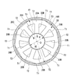
- FIG. 2 is a cross-sectional view taken along the line AA of FIG. 1 and shows a detailed configuration of the stator 19B viewed from the direction of the axis O.
- the stator 19B includes a stator core 20 and a coil 20C.
- the stator core 20 has a cylindrical shape centered on the axis O and has a yoke 20A whose outer peripheral surface is fixed to the inner peripheral surface of the housing 11 and a circumferential direction of the yoke 20A so as to protrude from the inner peripheral surface of the yoke 20A.
- a plurality of teeth 20B are formed spaced apart from each other.
- the stator core 20 is configured by laminating a plurality of electromagnetic steel plates in the vertical direction.
- a plurality of coils 20C are provided to correspond to the teeth 20B, and wound around the teeth 20B.
- a plurality of coils 20C are provided at intervals in the circumferential direction.
- the yoke 20A is in the shape of a regular polygon when viewed in the direction of the axis O.
- the yoke 20A in the present embodiment has a regular splay shape.
- Each apex angle of the yoke 20A is chamfered in an arc shape so as to fit on the inner peripheral surface of the housing 11.
- the chamfered portion is an interference fit with the inner peripheral surface of the housing 11 to form an abutting portion T1.
- the abutting portion T1 is formed by shrink fitting the stator core 20 to the housing 11. That is, after the housing 11 is heated and expanded by a burner or the like, the stator core 20 is inserted from the opening.
- the tightening margin (that is, the amount of deformation of the contact portion T1 in the radial direction of the axis O) of the contact portion T1 with respect to the housing 11 is 0.05 mm or more.
- the method is not limited to the above-described shrink fitting, and it is possible to use a cold fit, which is inserted into the housing 11 after the stator core 20 is cooled and contracted. .
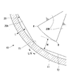
- L be the total length (total of the contact lengths of the housing 11 and the yoke 20A) of all (nine) contact portions T1 when viewed from the direction of the axis O
- d1 be the outer diameter of the yoke 20A.
- the outer diameter dimension d1 referred to here is, as shown in FIG. 2, the outermost periphery of one contact portion T1, the axis O (the center of the yoke 20A), and the contact portion T1 with the axis O. It refers to the length of a straight line connecting the inner circumferential surface of the housing 11 facing each other.
- each value of L and d1 satisfy the relationship of Formula (2). 0.1 ⁇ L / d1 ⁇ 0.35 (2)
- the width dimension (dimension in the radial direction of the axis O) of the yoke 20A is w
- the following equation (4) is satisfied between w and the above-mentioned outer diameter dimension d1. . w / d1 ⁇ 0.08 (4)
- each value of w and d1 satisfy
- a portion between the pair of adjacent contact portions T1 and T1 (a side portion of a regular octagon) is separated from the inner circumferential surface of the housing 11 to form a non-contact portion T2.
- the non-contacting portion T2 is a linear portion of the outer peripheral portion of the yoke 20A.
- the contact portion T1 and the non-contact portion T2 are continuously connected to each other. In other words, no step or the like is formed between the contact portion T1 and the non-contact portion T2.
- a slight gap is formed between the non-contacting portion T2 and a part of the inner peripheral surface of the housing 11 opposed thereto. The gap is a flow path for the high pressure air generated by the compression mechanism unit 10A to flow upward.
- the teeth 20B have a substantially plate shape extending in the radial direction of the axis O.
- the teeth 20B are integrally formed of the same material as the yoke 20A.
- the width dimension of the teeth 20B i.e., the dimension in the circumferential direction of the axis O
- a plurality of teeth 20B are provided on the inner peripheral surface of the yoke 20A at equal intervals in the circumferential direction of the axis O.
- the stator core 20 according to the present embodiment has nine teeth 20B. Each tooth 20B is provided radially inward of the non-contacting portion T2 of the yoke 20A.
- the positions of the contact portion T1 and the teeth 20B in the circumferential direction of the axis O are different from each other.
- the teeth 20B are provided at the central portion of the non-contacting portion T2 when viewed from the direction of the axis O.
- a radius section R having a curved shape (arc shape) as viewed from the direction of the axis O is formed at the radial outer end portion of the tooth 20B and the connection portion of the yoke 20A.
- the curvature radius of the radius section R is 1.5 mm or less. More preferably, the curvature radius of the radius section R is 0.5 mm or less.
- a radially inner end of the tooth 20B is provided with a collar B for holding a copper wire of the coil 20C.
- the collar portion B has a circumferential dimension larger than that of the teeth 20B.
- the inner peripheral surface of the flange portion B is opposed to the above-mentioned rotor 19A with a gap.
- the radially inner end surface of the flange portion B has an arc shape centered on the position of the axis O.
- the inner diameter d2 of the stator core 20 indicates the diameter of a virtual circle formed by the arcs of the plurality of flange portions B. d2 / d1 ⁇ 0.44 (6)
- each value of d1 and d2 satisfy
- the relationship of the equation (1), (2) or (3) is established between the length L of the contact portion T1 and the outer diameter d1 of the stator core 20. ing.
- the length of the contact portion T1 can be kept small, so that the compressive stress that the contact portion T1 receives from the housing 11 can be reduced. Thereby, it is possible to reduce the iron loss generated in stator core 20 when motor 18 is driven.
- the length L of the contact portion T1 can be reduced, and the length of the adjacent non-contact portion T2 can be secured large. That is, the gap between the non-contacting portion T2 and a part of the inner peripheral surface of the housing 11 opposed thereto can be increased.
- the gap is a flow path for the high pressure air generated by the compression mechanism unit 10A to flow upward. Therefore, high pressure air can be guided more smoothly.
- the relationship of the equation (4) or the equation (5) is established.
- the dimension of the yoke 20A can be reduced, and a large slot area of the motor 18 can be secured.
- the slot area refers to the cross-sectional area occupied by the copper wire portion in the total cross-sectional area of the coil 20C.
- the radius of curvature of the rounded section R formed at the connection between the inner circumferential surface of the yoke 20A and the end of the tooth 20B can be reduced.
- winding collapse of the coil 20C can be prevented, the slot area can be further expanded, and the motor 18 can be made more efficient.
- stator core 20 can be fixed to housing 11 more firmly and stably.
- the plate thickness t of the housing 11 can be secured large, the strength and pressure resistance of the housing 11 can be further increased.
- the embodiments of the present invention have been described above with reference to the drawings.
- said structure is an example and it is possible to add a various change to this.
- the configuration in which nine teeth 20B are provided has been described.
- the number of teeth 20B is not limited to nine, and various numbers can be adopted depending on the design and specifications.
- the shape of the yoke 20A is not limited to the above regular nine-sided shape, and may have another regular polygonal shape.
- the shape of the yoke 20A is not limited to the regular polygon shape, and may have an equilateral polygon shape. In this case, the contact length with respect to the inner circumferential surface of the housing 11 for each contact portion T1 also becomes uneven, but the value of the contact length L is the same as that described above for all the contact portions T1. It becomes the total value of the length.
- the efficiency increase obtained by one improvement measure is at most 0.1 to 0.. It is common to stay in the range of a few percent.
- the motor efficiency can be significantly improved by about 1%.
- a motor having a rotor rotatable about an axis and a stator core surrounding the rotor from the outer peripheral side about the axis, a compression mechanism section driven by the motor to compress refrigerant, a motor, and a compression mechanism section And a housing covering the above. According to the compressor of the present invention, the efficiency can be further improved.
Abstract
Priority Applications (2)
| Application Number | Priority Date | Filing Date | Title |
|---|---|---|---|
| AU2018306257A AU2018306257B2 (en) | 2017-07-26 | 2018-06-12 | Compressor |
| EP18837784.0A EP3661020B1 (fr) | 2017-07-26 | 2018-06-12 | Compresseur |
Applications Claiming Priority (2)
| Application Number | Priority Date | Filing Date | Title |
|---|---|---|---|
| JP2017-144508 | 2017-07-26 | ||
| JP2017144508A JP7067880B2 (ja) | 2017-07-26 | 2017-07-26 | 圧縮機 |
Publications (1)
| Publication Number | Publication Date |
|---|---|
| WO2019021658A1 true WO2019021658A1 (fr) | 2019-01-31 |
Family
ID=65040701
Family Applications (1)
| Application Number | Title | Priority Date | Filing Date |
|---|---|---|---|
| PCT/JP2018/022341 WO2019021658A1 (fr) | 2017-07-26 | 2018-06-12 | Compresseur |
Country Status (4)
| Country | Link |
|---|---|
| EP (1) | EP3661020B1 (fr) |
| JP (1) | JP7067880B2 (fr) |
| AU (1) | AU2018306257B2 (fr) |
| WO (1) | WO2019021658A1 (fr) |
Families Citing this family (2)
| Publication number | Priority date | Publication date | Assignee | Title |
|---|---|---|---|---|
| CN112713672B (zh) * | 2019-10-25 | 2022-03-22 | 佛山市威灵洗涤电机制造有限公司 | 电机及其装配结构 |
| WO2023112078A1 (fr) * | 2021-12-13 | 2023-06-22 | 三菱電機株式会社 | Stator, moteur, compresseur et dispositif à cycle de réfrigération |
Citations (6)
| Publication number | Priority date | Publication date | Assignee | Title |
|---|---|---|---|---|
| JPS5999669U (ja) * | 1982-12-24 | 1984-07-05 | 株式会社日立製作所 | 液体般送ポンプ |
| JPH0296494U (fr) * | 1989-01-19 | 1990-08-01 | ||
| JP2008271616A (ja) | 2007-04-16 | 2008-11-06 | Toshiba Carrier Corp | 密閉型圧縮機及びこれを用いた冷凍サイクル装置 |
| JP2010063344A (ja) * | 2008-08-06 | 2010-03-18 | Denso Corp | 燃料供給ポンプ |
| JP2015002650A (ja) * | 2013-06-18 | 2015-01-05 | ダイキン工業株式会社 | モータ及びそれを用いた圧縮機 |
| JP2017144508A (ja) | 2016-02-17 | 2017-08-24 | Kyb株式会社 | 芯出し装置 |
Family Cites Families (3)
| Publication number | Priority date | Publication date | Assignee | Title |
|---|---|---|---|---|
| JP4036148B2 (ja) * | 2002-07-23 | 2008-01-23 | 株式会社豊田自動織機 | 電動モータ及び電動コンプレッサ |
| US20070114874A1 (en) * | 2005-11-23 | 2007-05-24 | Daewoo Electronics Corporation | Motor having a stator and a rotor made of soft magnetic powder material |
| JP2007244150A (ja) * | 2006-03-10 | 2007-09-20 | Toyota Industries Corp | 電動モータ及び電動圧縮機 |
-
2017
- 2017-07-26 JP JP2017144508A patent/JP7067880B2/ja active Active
-
2018
- 2018-06-12 AU AU2018306257A patent/AU2018306257B2/en active Active
- 2018-06-12 EP EP18837784.0A patent/EP3661020B1/fr active Active
- 2018-06-12 WO PCT/JP2018/022341 patent/WO2019021658A1/fr unknown
Patent Citations (6)
| Publication number | Priority date | Publication date | Assignee | Title |
|---|---|---|---|---|
| JPS5999669U (ja) * | 1982-12-24 | 1984-07-05 | 株式会社日立製作所 | 液体般送ポンプ |
| JPH0296494U (fr) * | 1989-01-19 | 1990-08-01 | ||
| JP2008271616A (ja) | 2007-04-16 | 2008-11-06 | Toshiba Carrier Corp | 密閉型圧縮機及びこれを用いた冷凍サイクル装置 |
| JP2010063344A (ja) * | 2008-08-06 | 2010-03-18 | Denso Corp | 燃料供給ポンプ |
| JP2015002650A (ja) * | 2013-06-18 | 2015-01-05 | ダイキン工業株式会社 | モータ及びそれを用いた圧縮機 |
| JP2017144508A (ja) | 2016-02-17 | 2017-08-24 | Kyb株式会社 | 芯出し装置 |
Non-Patent Citations (1)
| Title |
|---|
| See also references of EP3661020A4 |
Also Published As
| Publication number | Publication date |
|---|---|
| AU2018306257A1 (en) | 2020-03-12 |
| JP7067880B2 (ja) | 2022-05-16 |
| EP3661020B1 (fr) | 2021-08-11 |
| EP3661020A4 (fr) | 2020-07-15 |
| AU2018306257B2 (en) | 2021-01-21 |
| EP3661020A1 (fr) | 2020-06-03 |
| JP2019030056A (ja) | 2019-02-21 |
Similar Documents
| Publication | Publication Date | Title |
|---|---|---|
| US11437877B2 (en) | Rotor, motor, compressor, and air conditioner | |
| US7504753B2 (en) | Motor | |
| JP4586599B2 (ja) | 圧縮機 | |
| CN107431394B (zh) | 压缩机以及制冷循环装置 | |
| WO2010016583A1 (fr) | Stator, moteur et compresseur | |
| JPWO2007116431A1 (ja) | 単相電動機及び密閉型圧縮機 | |
| WO2016143047A1 (fr) | Rotor de moteur, moteur de compresseur l'utilisant, et compresseur | |
| JP5143166B2 (ja) | 単相誘導電動機及び密閉型圧縮機 | |
| WO2019021658A1 (fr) | Compresseur | |
| WO2019043850A1 (fr) | Rotor, moteur électrique, compresseur, et dispositif de climatiseur | |
| JP2005042632A (ja) | 流体機械 | |
| KR102287164B1 (ko) | 전동기 및 이를 구비한 압축기 | |
| JP2007205227A (ja) | 圧縮機 | |
| JP5862332B2 (ja) | ロータおよび圧縮機 | |
| JP6470598B2 (ja) | 永久磁石式回転電機、並びにそれを用いる圧縮機 | |
| JP7122145B2 (ja) | ステータ、モータ、及び圧縮機 | |
| WO2017047338A1 (fr) | Compresseur électrique hermétique | |
| JP2010081735A (ja) | ステータ、モータおよび圧縮機 | |
| WO2019123531A1 (fr) | Stator et moteur électrique qui en est pourvu | |
| WO2021201223A1 (fr) | Compresseur rotatif | |
| WO2023139637A1 (fr) | Compresseur rotatif | |
| JP2012120365A (ja) | ロータ、モータおよび圧縮機 | |
| JP7169911B2 (ja) | 電動機及びこれを備える機器 | |
| JP7432304B2 (ja) | 横置き型電動機 | |
| KR20200087601A (ko) | 구동 모터 및 이를 구비하는 압축기 |
Legal Events
| Date | Code | Title | Description |
|---|---|---|---|
| 121 | Ep: the epo has been informed by wipo that ep was designated in this application |
Ref document number: 18837784 Country of ref document: EP Kind code of ref document: A1 |
|
| NENP | Non-entry into the national phase |
Ref country code: DE |
|
| ENP | Entry into the national phase |
Ref document number: 2018837784 Country of ref document: EP Effective date: 20200224 |
|
| ENP | Entry into the national phase |
Ref document number: 2018306257 Country of ref document: AU Date of ref document: 20180612 Kind code of ref document: A |