WO2019021658A1 - Compressor - Google Patents
Compressor Download PDFInfo
- Publication number
- WO2019021658A1 WO2019021658A1 PCT/JP2018/022341 JP2018022341W WO2019021658A1 WO 2019021658 A1 WO2019021658 A1 WO 2019021658A1 JP 2018022341 W JP2018022341 W JP 2018022341W WO 2019021658 A1 WO2019021658 A1 WO 2019021658A1
- Authority
- WO
- WIPO (PCT)
- Prior art keywords
- stator core
- yoke
- motor
- relationship
- housing
- Prior art date
Links
Images


Classifications
-
- H—ELECTRICITY
- H02—GENERATION; CONVERSION OR DISTRIBUTION OF ELECTRIC POWER
- H02K—DYNAMO-ELECTRIC MACHINES
- H02K1/00—Details of the magnetic circuit
- H02K1/06—Details of the magnetic circuit characterised by the shape, form or construction
- H02K1/12—Stationary parts of the magnetic circuit
- H02K1/18—Means for mounting or fastening magnetic stationary parts on to, or to, the stator structures
- H02K1/185—Means for mounting or fastening magnetic stationary parts on to, or to, the stator structures to outer stators
-
- F—MECHANICAL ENGINEERING; LIGHTING; HEATING; WEAPONS; BLASTING
- F04—POSITIVE - DISPLACEMENT MACHINES FOR LIQUIDS; PUMPS FOR LIQUIDS OR ELASTIC FLUIDS
- F04B—POSITIVE-DISPLACEMENT MACHINES FOR LIQUIDS; PUMPS
- F04B39/00—Component parts, details, or accessories, of pumps or pumping systems specially adapted for elastic fluids, not otherwise provided for in, or of interest apart from, groups F04B25/00 - F04B37/00
-
- F—MECHANICAL ENGINEERING; LIGHTING; HEATING; WEAPONS; BLASTING
- F04—POSITIVE - DISPLACEMENT MACHINES FOR LIQUIDS; PUMPS FOR LIQUIDS OR ELASTIC FLUIDS
- F04C—ROTARY-PISTON, OR OSCILLATING-PISTON, POSITIVE-DISPLACEMENT MACHINES FOR LIQUIDS; ROTARY-PISTON, OR OSCILLATING-PISTON, POSITIVE-DISPLACEMENT PUMPS
- F04C29/00—Component parts, details or accessories of pumps or pumping installations, not provided for in groups F04C18/00 - F04C28/00
-
- H—ELECTRICITY
- H02—GENERATION; CONVERSION OR DISTRIBUTION OF ELECTRIC POWER
- H02K—DYNAMO-ELECTRIC MACHINES
- H02K1/00—Details of the magnetic circuit
- H02K1/06—Details of the magnetic circuit characterised by the shape, form or construction
- H02K1/12—Stationary parts of the magnetic circuit
- H02K1/14—Stator cores with salient poles
- H02K1/146—Stator cores with salient poles consisting of a generally annular yoke with salient poles
-
- H—ELECTRICITY
- H02—GENERATION; CONVERSION OR DISTRIBUTION OF ELECTRIC POWER
- H02K—DYNAMO-ELECTRIC MACHINES
- H02K2213/00—Specific aspects, not otherwise provided for and not covered by codes H02K2201/00 - H02K2211/00
- H02K2213/03—Machines characterised by numerical values, ranges, mathematical expressions or similar information
Definitions
- the present invention relates to a compressor.
- Priority is claimed on Japanese Patent Application No. 201-144508, filed July 26, 2017, the content of which is incorporated herein by reference.
- a rotary compressor is known as a type of compressor used for an air conditioner.
- the rotary compressor includes a motor driven by an external power supply, and a compressor body connected to an output shaft of the motor.
- the compressor body has a crankshaft rotationally driven by an output shaft, a piston rotor integrally provided on the crankshaft, and a cylinder covering the piston rotor.
- the eccentric rotation of the piston rotor in the cylinder at a position different from the output shaft compresses the air in the cylinder and generates high pressure compressed air.
- the motor described in Patent Document 1 has a rotor (rotor) provided on an output shaft, and a substantially annular stator core (stator) to which a plurality of coils covering the rotor from the outer peripheral side are attached. ing.
- the outer peripheral surface of the stator core is interference-fit to the inner peripheral surface of the housing of the rotary compressor through a process such as shrink fitting.
- the copper loss is an energy loss caused by the resistive component of the copper wire constituting the coil.
- the iron loss is an energy loss due to the physical properties and the shape of the stator core on which the coil is wound.
- copper loss can be reduced and high efficiency of the motor can be achieved.
- concentration of compressive stress that the housing exerts on the stator core is likely to occur in the interference fitted state.
- iron loss of the stator core may increase, and the effect of reducing copper loss may be lost. That is, there was a possibility that it would be difficult to increase the efficiency of the motor.
- the present invention has been made to solve the above-mentioned problems, and it is an object of the present invention to provide a compressor provided with a more efficient motor.
- a compressor is driven by a motor having a rotor rotatable about an axis and a stator core surrounding the rotor from the outer peripheral side around the axis, and the refrigerant is a refrigerant
- a compressor including a compression mechanism portion for compressing an electric motor, and the motor and a housing covering the compression mechanism portion, and the outer peripheral surface of the stator core is tightly fitted to the inner peripheral surface of the housing
- a plurality of contact portions and a plurality of non-contact portions provided respectively adjacent to the contact portions and separated from the inner circumferential surface are formed, and the plurality of contact portions when viewed from the axial direction
- the relationship of the equation (1) is satisfied.
- formula (3) May satisfy the relationship of 0.1 ⁇ L / d1 ⁇ 0.18 (3)
- the stator core includes an annular yoke having the contact portion and the non-contact portion, and a plurality of teeth extending radially inward of the axis from the inner circumferential surface of the yoke.
- the relationship of the equation (4) may be satisfied.
- the slot area refers to the cross-sectional area occupied by the copper wire portion in the total cross-sectional area of the coil.
- the slot area of the motor can be further increased. Thereby, the efficiency of the motor can be further enhanced.
- the slot area refers to the cross-sectional area occupied by the copper wire portion in the total cross-sectional area of the coil.
- the stator core includes: an annular yoke having the contact portion and the non-contact portion; and teeth extending radially inward of the axial line from the inner circumferential surface of the yoke; A curved radius section is formed at the connection between the inner circumferential surface of the yoke and the radial outer end of the teeth as viewed in the axial direction, and the radius of curvature of the radius section is It may be 1.5 mm or less.
- the radius of curvature of the rounded section formed at the connection between the inner circumferential surface of the yoke and the end of the teeth can be reduced. As a result, it is possible to prevent the winding collapse of the coil, and to further increase the slot area and to achieve high efficiency of the motor.
- the radius of curvature of the radius section may be 0.5 mm or less.
- the motor can be made more efficient.
- the motor can be made more efficient.
- the margin of the stator core with respect to the housing may be 0.05 mm or more.
- the stator core can be more firmly and stably fixed to the housing.
- the relationship of the equation (8) may be satisfied. t / d1 ⁇ 0.03 (8)
- the plate thickness of the housing can be secured large, the strength and pressure resistance of the housing can be further increased.
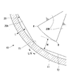
- FIG. 2 is a cross-sectional view taken along the line AA of FIG. It is a principal part enlarged view of FIG. It is a table
- surface which shows the relationship of the value of L / d1 and iron loss, copper loss, and motor efficiency which concern on the Example of this invention.
- a compressor 10 according to an embodiment of the present invention will be described with reference to FIGS. 1 to 3.
- the compressor 10 according to the present embodiment includes a motor 18 driven by an external power supply, a compression mechanism portion 10A for compressing a refrigerant by being driven by the motor 18, a motor 18 and a compression mechanism And a housing 11 covering the portion 10A.
- the compression mechanism portion 10A is a so-called two-cylinder type rotary compressor in which disk-shaped cylinders 12A and 12B are provided in upper and lower two stages in a cylindrical housing 11.
- the housing 11 encloses the cylinders 12A and 12B to form a discharge space V in which the compressed refrigerant is discharged.
- cylindrical piston rotors 13A and 13B each having an outer diameter smaller than the inner side of the cylinder inner wall surface are disposed.
- the piston rotors 13A and 13B are respectively inserted into and fixed to the eccentric shaft portions 14A and 14B of the rotation axis along the central axis of the housing 11.
- the piston rotor 13A of the upper cylinder and the lower piston rotor 13B are provided so that their phases differ by 180 °. Further, a disc-shaped partition plate 15 is provided between the upper and lower cylinders 12A and 12B. The space R in the cylinder 12A on the upper stage side and the space R on the lower stage side are divided by the partition plate 15 into the compression chambers R1 and R2 without communicating with each other.
- the crankshaft 16 is rotatably supported about the axis O by an upper bearing portion 17A fixed to the cylinder 12A and a lower bearing portion 17B fixed to the cylinder 12B.
- the crankshaft 16 has eccentric shaft portions 14A and 14B offset in a direction perpendicular to the center line of the crankshaft 16. When the eccentric shaft portions 14A and 14B turn around the central axis of the crankshaft 16, the upper and lower piston rotors 13A and 13B follow this turning and eccentrically rotate in the cylinders 12A and 12B.
- crankshaft 16 protrudes upward from the upper bearing portion 17A (that is, in a direction in which the motor 18 is located when viewed from the compression mechanism portion 10A).
- a rotor 19A of a motor 18 for rotationally driving the crankshaft 16 is integrally provided at one end of the crankshaft 16 in the direction of the axis O.
- a stator 19B is fixed to the inner peripheral surface of the housing 11 so as to face the outer peripheral portion of the rotor 19A.
- an accumulator 24 for gas-liquid separation of the refrigerant prior to the supply to the compressor 10 is fixed to the housing 11 via a stay 25.
- the accumulator 24 is provided with suction pipes 26A, 26B for drawing the refrigerant in the accumulator 24 into the compressor 10.
- the tips of the suction pipes 26A, 26B are connected to the suction ports 23A, 23B through the openings 22A, 22B.
- the compressor 10 takes in the refrigerant from the suction port 24 a of the accumulator 24 to the inside of the accumulator 24. Specifically, the refrigerant is separated into gas and liquid in the accumulator 24, and the gas phase is separated from the suction pipes 26A and 26B through the suction ports 23A and 23B of the cylinders 12A and 12B, and is the internal space of the cylinders 12A and 12B. It supplies to compression chamber R1 and R2. Then, as the piston rotors 13A and 13B eccentrically rotate, the volumes of the compression chambers R1 and R2 gradually decrease and the refrigerant is compressed. The refrigerant passes around the motor 18 and is then discharged to a pipe 27 constituting a refrigeration cycle via a discharge port provided at the top.
- the motor 18 has a rotor 19A rotatable around an axis O, and a stator 19B surrounding the rotor 19A from the outer peripheral side around the axis O.
- the rotor 19A is provided at the upper end of the crankshaft 16.
- the rotor 19A has a permanent magnet inside, and its outer shape is substantially cylindrical with the axis O as a center.
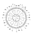
- FIG. 2 is a cross-sectional view taken along the line AA of FIG. 1 and shows a detailed configuration of the stator 19B viewed from the direction of the axis O.
- the stator 19B includes a stator core 20 and a coil 20C.
- the stator core 20 has a cylindrical shape centered on the axis O and has a yoke 20A whose outer peripheral surface is fixed to the inner peripheral surface of the housing 11 and a circumferential direction of the yoke 20A so as to protrude from the inner peripheral surface of the yoke 20A.
- a plurality of teeth 20B are formed spaced apart from each other.
- the stator core 20 is configured by laminating a plurality of electromagnetic steel plates in the vertical direction.
- a plurality of coils 20C are provided to correspond to the teeth 20B, and wound around the teeth 20B.
- a plurality of coils 20C are provided at intervals in the circumferential direction.
- the yoke 20A is in the shape of a regular polygon when viewed in the direction of the axis O.
- the yoke 20A in the present embodiment has a regular splay shape.
- Each apex angle of the yoke 20A is chamfered in an arc shape so as to fit on the inner peripheral surface of the housing 11.
- the chamfered portion is an interference fit with the inner peripheral surface of the housing 11 to form an abutting portion T1.
- the abutting portion T1 is formed by shrink fitting the stator core 20 to the housing 11. That is, after the housing 11 is heated and expanded by a burner or the like, the stator core 20 is inserted from the opening.
- the tightening margin (that is, the amount of deformation of the contact portion T1 in the radial direction of the axis O) of the contact portion T1 with respect to the housing 11 is 0.05 mm or more.
- the method is not limited to the above-described shrink fitting, and it is possible to use a cold fit, which is inserted into the housing 11 after the stator core 20 is cooled and contracted. .
- L be the total length (total of the contact lengths of the housing 11 and the yoke 20A) of all (nine) contact portions T1 when viewed from the direction of the axis O
- d1 be the outer diameter of the yoke 20A.
- the outer diameter dimension d1 referred to here is, as shown in FIG. 2, the outermost periphery of one contact portion T1, the axis O (the center of the yoke 20A), and the contact portion T1 with the axis O. It refers to the length of a straight line connecting the inner circumferential surface of the housing 11 facing each other.
- each value of L and d1 satisfy the relationship of Formula (2). 0.1 ⁇ L / d1 ⁇ 0.35 (2)
- the width dimension (dimension in the radial direction of the axis O) of the yoke 20A is w
- the following equation (4) is satisfied between w and the above-mentioned outer diameter dimension d1. . w / d1 ⁇ 0.08 (4)
- each value of w and d1 satisfy
- a portion between the pair of adjacent contact portions T1 and T1 (a side portion of a regular octagon) is separated from the inner circumferential surface of the housing 11 to form a non-contact portion T2.
- the non-contacting portion T2 is a linear portion of the outer peripheral portion of the yoke 20A.
- the contact portion T1 and the non-contact portion T2 are continuously connected to each other. In other words, no step or the like is formed between the contact portion T1 and the non-contact portion T2.
- a slight gap is formed between the non-contacting portion T2 and a part of the inner peripheral surface of the housing 11 opposed thereto. The gap is a flow path for the high pressure air generated by the compression mechanism unit 10A to flow upward.
- the teeth 20B have a substantially plate shape extending in the radial direction of the axis O.
- the teeth 20B are integrally formed of the same material as the yoke 20A.
- the width dimension of the teeth 20B i.e., the dimension in the circumferential direction of the axis O
- a plurality of teeth 20B are provided on the inner peripheral surface of the yoke 20A at equal intervals in the circumferential direction of the axis O.
- the stator core 20 according to the present embodiment has nine teeth 20B. Each tooth 20B is provided radially inward of the non-contacting portion T2 of the yoke 20A.
- the positions of the contact portion T1 and the teeth 20B in the circumferential direction of the axis O are different from each other.
- the teeth 20B are provided at the central portion of the non-contacting portion T2 when viewed from the direction of the axis O.
- a radius section R having a curved shape (arc shape) as viewed from the direction of the axis O is formed at the radial outer end portion of the tooth 20B and the connection portion of the yoke 20A.
- the curvature radius of the radius section R is 1.5 mm or less. More preferably, the curvature radius of the radius section R is 0.5 mm or less.
- a radially inner end of the tooth 20B is provided with a collar B for holding a copper wire of the coil 20C.
- the collar portion B has a circumferential dimension larger than that of the teeth 20B.
- the inner peripheral surface of the flange portion B is opposed to the above-mentioned rotor 19A with a gap.
- the radially inner end surface of the flange portion B has an arc shape centered on the position of the axis O.
- the inner diameter d2 of the stator core 20 indicates the diameter of a virtual circle formed by the arcs of the plurality of flange portions B. d2 / d1 ⁇ 0.44 (6)
- each value of d1 and d2 satisfy
- the relationship of the equation (1), (2) or (3) is established between the length L of the contact portion T1 and the outer diameter d1 of the stator core 20. ing.
- the length of the contact portion T1 can be kept small, so that the compressive stress that the contact portion T1 receives from the housing 11 can be reduced. Thereby, it is possible to reduce the iron loss generated in stator core 20 when motor 18 is driven.
- the length L of the contact portion T1 can be reduced, and the length of the adjacent non-contact portion T2 can be secured large. That is, the gap between the non-contacting portion T2 and a part of the inner peripheral surface of the housing 11 opposed thereto can be increased.
- the gap is a flow path for the high pressure air generated by the compression mechanism unit 10A to flow upward. Therefore, high pressure air can be guided more smoothly.
- the relationship of the equation (4) or the equation (5) is established.
- the dimension of the yoke 20A can be reduced, and a large slot area of the motor 18 can be secured.
- the slot area refers to the cross-sectional area occupied by the copper wire portion in the total cross-sectional area of the coil 20C.
- the radius of curvature of the rounded section R formed at the connection between the inner circumferential surface of the yoke 20A and the end of the tooth 20B can be reduced.
- winding collapse of the coil 20C can be prevented, the slot area can be further expanded, and the motor 18 can be made more efficient.
- stator core 20 can be fixed to housing 11 more firmly and stably.
- the plate thickness t of the housing 11 can be secured large, the strength and pressure resistance of the housing 11 can be further increased.
- the embodiments of the present invention have been described above with reference to the drawings.
- said structure is an example and it is possible to add a various change to this.
- the configuration in which nine teeth 20B are provided has been described.
- the number of teeth 20B is not limited to nine, and various numbers can be adopted depending on the design and specifications.
- the shape of the yoke 20A is not limited to the above regular nine-sided shape, and may have another regular polygonal shape.
- the shape of the yoke 20A is not limited to the regular polygon shape, and may have an equilateral polygon shape. In this case, the contact length with respect to the inner circumferential surface of the housing 11 for each contact portion T1 also becomes uneven, but the value of the contact length L is the same as that described above for all the contact portions T1. It becomes the total value of the length.
- the efficiency increase obtained by one improvement measure is at most 0.1 to 0.. It is common to stay in the range of a few percent.
- the motor efficiency can be significantly improved by about 1%.
- a motor having a rotor rotatable about an axis and a stator core surrounding the rotor from the outer peripheral side about the axis, a compression mechanism section driven by the motor to compress refrigerant, a motor, and a compression mechanism section And a housing covering the above. According to the compressor of the present invention, the efficiency can be further improved.
Abstract
Description
本願は、2017年7月26日に、日本に出願された特願2017-144508号に基づき優先権を主張し、その内容をここに援用する。 The present invention relates to a compressor.
Priority is claimed on Japanese Patent Application No. 201-144508, filed July 26, 2017, the content of which is incorporated herein by reference.
0.1≦L/d1≦1.00 ・・・(1) According to a first aspect of the present invention, a compressor is driven by a motor having a rotor rotatable about an axis and a stator core surrounding the rotor from the outer peripheral side around the axis, and the refrigerant is a refrigerant A compressor including a compression mechanism portion for compressing an electric motor, and the motor and a housing covering the compression mechanism portion, and the outer peripheral surface of the stator core is tightly fitted to the inner peripheral surface of the housing A plurality of contact portions and a plurality of non-contact portions provided respectively adjacent to the contact portions and separated from the inner circumferential surface are formed, and the plurality of contact portions when viewed from the axial direction Assuming that the total length of the contact portions is L and the outer diameter of the stator core is d1, the relationship of the equation (1) is satisfied.
0.1 ≦ L / d1 ≦ 1.00 (1)
0.1≦L/d1≦0.35 ・・・(2) According to the second aspect of the present invention, when a total length of the plurality of contact portions when viewed from the axial direction is L and an outer diameter dimension of the stator core is d1, The relationship of the equation (2) may be satisfied.
0.1 ≦ L / d1 ≦ 0.35 (2)
0.1≦L/d1≦0.18 ・・・(3) According to the third aspect of the present invention, when the sum of the lengths of the plurality of contact portions when viewed from the axial direction is L, and the outer diameter of the stator core is d1, formula (3) May satisfy the relationship of
0.1 ≦ L / d1 ≦ 0.18 (3)
w/d1≦0.08 ・・・(4) According to the fourth aspect of the present invention, the stator core includes an annular yoke having the contact portion and the non-contact portion, and a plurality of teeth extending radially inward of the axis from the inner circumferential surface of the yoke. And when the dimension of the yoke in the radial direction of the axis is w, the relationship of the equation (4) may be satisfied.
w / d1 ≦ 0.08 (4)
w/d1≦0.06 ・・・(5) According to the fifth aspect of the present invention, when the length of the yoke in the direction orthogonal to the radial direction is w when viewed from the axial direction, the relationship of the equation (5) may be satisfied.
w / d1 ≦ 0.06 (5)
d2/d1≧0.44 ・・・(6) According to the eighth aspect of the present invention, when the inside diameter of the stator core is d2, the relationship of the equation (6) may be satisfied.
d2 / d1 ≧ 0.44 (6)
d2/d1≧0.58 ・・・(7) According to the ninth aspect of the present invention, when the inside diameter of the stator core is d2, the relationship of the equation (7) may be satisfied.
d2 / d1 ≧ 0.58 (7)
t/d1≧0.03 ・・・(8) According to the eleventh aspect of the present invention, when the plate thickness of the housing is t, the relationship of the equation (8) may be satisfied.
t / d1 ≧ 0.03 (8)
上段側のシリンダのピストンロータ13Aと、下段側のピストンロータ13Bとは、その位相が互いに180°だけ異なるように設けられている。
また、上下のシリンダ12A、12Bの間には、ディスク状の仕切板15が設けられている。仕切板15により、上段側のシリンダ12A内の空間Rと、下段側の空間Rとが互いに連通せずに圧縮室R1とR2とに仕切られている。 The
The
Further, a disc-shaped
クランクシャフト16は、クランクシャフト16の中心線に直交する方向にオフセットした偏心軸部14A、14Bを有している。これら偏心軸部14A、14Bがクランクシャフト16の中心軸線回りに旋回することで、上下のピストンロータ13A、13Bがこの旋回に追従してシリンダ12A、12B内で、偏心回転する。 The
The
そして、ピストンロータ13A、13Bが偏心回転することにより、圧縮室R1、R2の容積が徐々に減少して冷媒が圧縮される。この冷媒は、モータ18の周囲を通過してから、上部に設けられた吐出口を経由して冷凍サイクルを構成する配管27に排出される。 The
Then, as the
0.1≦L/d1≦1.00 ・・・(1) Let L be the total length (total of the contact lengths of the
0.1 ≦ L / d1 ≦ 1.00 (1)
0.1≦L/d1≦0.35 ・・・(2) Furthermore, it is more preferable that each value of L and d1 satisfy the relationship of Formula (2).
0.1 ≦ L / d1 ≦ 0.35 (2)
0.1≦L/d1≦0.18 ・・・(3) In addition, it is most preferable that the values of L and d1 satisfy the relationship of equation (3).
0.1 ≦ L / d1 ≦ 0.18 (3)
w/d1≦0.08 ・・・(4) Further, when the width dimension (dimension in the radial direction of the axis O) of the
w / d1 ≦ 0.08 (4)
w/d1≦0.06 ・・・(5) In addition, it is more preferable that each value of w and d1 satisfy | fill the relationship of (5) Formula.
w / d1 ≦ 0.06 (5)
d2/d1≧0.44 ・・・(6) Here, when the inside diameter size of the
d2 / d1 ≧ 0.44 (6)
d2/d1≧0.58 ・・・(7) In addition, it is more preferable that each value of d1 and d2 satisfy | fill the relationship of (7) Formula.
d2 / d1 ≧ 0.58 (7)
t/d1≧0.03 ・・・(8) Furthermore, when the plate thickness of the
t / d1 ≧ 0.03 (8)
10A 圧縮機構部
11 ハウジング
12A,12B シリンダ
13A,13B ピストンロータ
16 クランクシャフト
18 モータ
19A ロータ
19B ステータ
20 ステータコア
20A ヨーク
20B ティース
20C コイル
22A、22B 開口
23A、23B 吸入ポート
24 アキュムレータ
25 ステー
26A、26B 吸入管
27 配管
B つば部
O 軸線
R アール区間 DESCRIPTION OF
Claims (11)
- 軸線回りに回転可能なロータ、及び前記軸線を中心として前記ロータを外周側から囲むステータコアを有するモータと、
前記モータによって駆動されて、冷媒を圧縮する圧縮機構部と、
前記モータ、及び前記圧縮機構部を覆うハウジングと、
を備える圧縮機であって、
前記ステータコアの外周面には、前記ハウジングの内周面に締まり嵌めされている複数の当接部と、それぞれ該当接部に隣接して設けられ、前記内周面から離間している複数の非当接部とが形成され、
前記軸線方向から見た場合の前記複数の当接部の長さの合計をLとし、前記ステータコアの外径寸法をd1としたとき、(1)式の関係を満たす圧縮機。
0.1≦L/d1≦1.00 ・・・(1) A motor having a rotor rotatable about an axis, and a stator core surrounding the rotor from an outer peripheral side about the axis;
A compression mechanism unit driven by the motor to compress the refrigerant;
A housing that covers the motor and the compression mechanism;
A compressor comprising
On the outer peripheral surface of the stator core, there are a plurality of contact portions which are fitted tightly to the inner peripheral surface of the housing, and a plurality of non-contact members which are provided adjacent to the respective contact portions and which are separated from the inner peripheral surface. The contact portion is formed,
A compressor that satisfies the relationship of Formula (1), where L is the total length of the plurality of contact portions when viewed from the axial direction, and d1 is the outer diameter of the stator core.
0.1 ≦ L / d1 ≦ 1.00 (1) - 前記軸線方向から見た場合の前記複数の当接部の長さの合計をLとし、前記ステータコアの外径寸法をd1としたとき、(2)式の関係を満たす請求項1に記載の圧縮機。
0.1≦L/d1≦0.35 ・・・(2) When the sum of lengths of the plurality of contact portions when viewed from the axial direction is L, and the outer diameter dimension of the stator core is d1, the compression according to claim 1 satisfying the relationship of equation (2). Machine.
0.1 ≦ L / d1 ≦ 0.35 (2) - 前記軸線方向から見た場合の前記複数の当接部の長さの合計をLとし、前記ステータコアの外径寸法をd1としたとき、(3)式の関係を満たす請求項1又は2に記載の圧縮機。
0.1≦L/d1≦0.18 ・・・(3) The sum of the lengths of the plurality of contact portions when viewed from the axial direction is L, and the outer diameter of the stator core is d1. Compressor.
0.1 ≦ L / d1 ≦ 0.18 (3) - 前記ステータコアは、前記当接部及び前記非当接部を有する環状のヨークと、該ヨークの内周面から前記軸線の径方向内側に延びる複数のティースと、を有し、
前記軸線の径方向における前記ヨークの寸法をwとしたとき、(4)式の関係を満たす請求項1から3のいずれか一項に記載の圧縮機。
w/d1≦0.08 ・・・(4) The stator core has an annular yoke having the contact portion and the non-contact portion, and a plurality of teeth extending inward in the radial direction of the axis from the inner circumferential surface of the yoke,
The compressor according to any one of claims 1 to 3, wherein when the dimension of the yoke in the radial direction of the axis is w, the relationship of the equation (4) is satisfied.
w / d1 ≦ 0.08 (4) - 前記軸線方向から見た場合の、径方向に直交する方向における前記ヨークの長さをwとしたとき、(5)式の関係を満たす請求項4に記載の圧縮機。
w/d1≦0.06 ・・・(5) The compressor according to claim 4, wherein when the length of the yoke in the direction orthogonal to the radial direction when viewed from the axial direction is w, the relationship of the formula (5) is satisfied.
w / d1 ≦ 0.06 (5) - 前記ステータコアは、前記当接部及び前記非当接部を有する環状のヨークと、該ヨークの内周面から軸線の径方向内側に延びるティースと、を有し、
前記軸線方向から見て、前記ヨークの内周面と、前記ティースの径方向外側の端部との接続部には曲線状のアール区間が形成され、該アール区間の曲率半径が、1.5mm以下である請求項1から5のいずれか一項に記載の圧縮機。 The stator core has an annular yoke having the contact portion and the non-contact portion, and teeth extending radially inward of an axial line from an inner circumferential surface of the yoke,
As viewed from the axial direction, a curved radius section is formed at the connection between the inner circumferential surface of the yoke and the radial outer end of the teeth, and the radius of curvature of the radius section is 1.5 mm. The compressor according to any one of claims 1 to 5, which is the following. - 前記アール区間の曲率半径が、0.5mm以下である請求項6に記載の圧縮機。 The compressor according to claim 6, wherein the radius of curvature of the radius section is 0.5 mm or less.
- 前記ステータコアの内径寸法をd2としたとき、(6)式の関係を満たす請求項1から7のいずれか一項に記載の圧縮機。
d2/d1≧0.44 ・・・(6) The compressor according to any one of claims 1 to 7, wherein when the inner diameter of the stator core is d2, the relationship of the equation (6) is satisfied.
d2 / d1 ≧ 0.44 (6) - 前記ステータコアの内径寸法をd2としたとき、(7)式の関係を満たす請求項8に記載の圧縮機。
d2/d1≧0.58 ・・・(7) The compressor according to claim 8, wherein when the inner diameter of the stator core is d2, the relationship of the formula (7) is satisfied.
d2 / d1 ≧ 0.58 (7) - 前記ハウジングに対する前記ステータコアの締めしろが、0.05mm以上である請求項1から9のいずれか一項に記載の圧縮機。 The compressor according to any one of claims 1 to 9, wherein an interference of the stator core with respect to the housing is 0.05 mm or more.
- 前記ハウジングの板厚をtとしたとき、(8)式の関係を満たす請求項1から10のいずれか一項に記載の圧縮機。
t/d1≧0.03 ・・・(8) The compressor according to any one of claims 1 to 10, wherein the relationship of the equation (8) is satisfied, where t is a thickness of the housing.
t / d1 ≧ 0.03 (8)
Priority Applications (2)
| Application Number | Priority Date | Filing Date | Title |
|---|---|---|---|
| EP18837784.0A EP3661020B1 (en) | 2017-07-26 | 2018-06-12 | Compressor |
| AU2018306257A AU2018306257B2 (en) | 2017-07-26 | 2018-06-12 | Compressor |
Applications Claiming Priority (2)
| Application Number | Priority Date | Filing Date | Title |
|---|---|---|---|
| JP2017-144508 | 2017-07-26 | ||
| JP2017144508A JP7067880B2 (en) | 2017-07-26 | 2017-07-26 | Compressor |
Publications (1)
| Publication Number | Publication Date |
|---|---|
| WO2019021658A1 true WO2019021658A1 (en) | 2019-01-31 |
Family
ID=65040701
Family Applications (1)
| Application Number | Title | Priority Date | Filing Date |
|---|---|---|---|
| PCT/JP2018/022341 WO2019021658A1 (en) | 2017-07-26 | 2018-06-12 | Compressor |
Country Status (4)
| Country | Link |
|---|---|
| EP (1) | EP3661020B1 (en) |
| JP (1) | JP7067880B2 (en) |
| AU (1) | AU2018306257B2 (en) |
| WO (1) | WO2019021658A1 (en) |
Families Citing this family (2)
| Publication number | Priority date | Publication date | Assignee | Title |
|---|---|---|---|---|
| CN112713672B (en) * | 2019-10-25 | 2022-03-22 | 佛山市威灵洗涤电机制造有限公司 | Motor and assembly structure thereof |
| JPWO2023112078A1 (en) * | 2021-12-13 | 2023-06-22 |
Citations (6)
| Publication number | Priority date | Publication date | Assignee | Title |
|---|---|---|---|---|
| JPS5999669U (en) * | 1982-12-24 | 1984-07-05 | 株式会社日立製作所 | liquid general pump |
| JPH0296494U (en) * | 1989-01-19 | 1990-08-01 | ||
| JP2008271616A (en) | 2007-04-16 | 2008-11-06 | Toshiba Carrier Corp | Enclosed compressor and refrigeration cycle device using the same |
| JP2010063344A (en) * | 2008-08-06 | 2010-03-18 | Denso Corp | Fuel pump |
| JP2015002650A (en) * | 2013-06-18 | 2015-01-05 | ダイキン工業株式会社 | Motor and compressor employing the same |
| JP2017144508A (en) | 2016-02-17 | 2017-08-24 | Kyb株式会社 | Centering device |
Family Cites Families (3)
| Publication number | Priority date | Publication date | Assignee | Title |
|---|---|---|---|---|
| JP4036148B2 (en) * | 2002-07-23 | 2008-01-23 | 株式会社豊田自動織機 | Electric motor and electric compressor |
| US20070114874A1 (en) * | 2005-11-23 | 2007-05-24 | Daewoo Electronics Corporation | Motor having a stator and a rotor made of soft magnetic powder material |
| JP2007244150A (en) * | 2006-03-10 | 2007-09-20 | Toyota Industries Corp | Electric motor and motor-driven compressor |
-
2017
- 2017-07-26 JP JP2017144508A patent/JP7067880B2/en active Active
-
2018
- 2018-06-12 WO PCT/JP2018/022341 patent/WO2019021658A1/en unknown
- 2018-06-12 AU AU2018306257A patent/AU2018306257B2/en active Active
- 2018-06-12 EP EP18837784.0A patent/EP3661020B1/en active Active
Patent Citations (6)
| Publication number | Priority date | Publication date | Assignee | Title |
|---|---|---|---|---|
| JPS5999669U (en) * | 1982-12-24 | 1984-07-05 | 株式会社日立製作所 | liquid general pump |
| JPH0296494U (en) * | 1989-01-19 | 1990-08-01 | ||
| JP2008271616A (en) | 2007-04-16 | 2008-11-06 | Toshiba Carrier Corp | Enclosed compressor and refrigeration cycle device using the same |
| JP2010063344A (en) * | 2008-08-06 | 2010-03-18 | Denso Corp | Fuel pump |
| JP2015002650A (en) * | 2013-06-18 | 2015-01-05 | ダイキン工業株式会社 | Motor and compressor employing the same |
| JP2017144508A (en) | 2016-02-17 | 2017-08-24 | Kyb株式会社 | Centering device |
Non-Patent Citations (1)
| Title |
|---|
| See also references of EP3661020A4 |
Also Published As
| Publication number | Publication date |
|---|---|
| EP3661020A1 (en) | 2020-06-03 |
| EP3661020A4 (en) | 2020-07-15 |
| AU2018306257B2 (en) | 2021-01-21 |
| EP3661020B1 (en) | 2021-08-11 |
| AU2018306257A1 (en) | 2020-03-12 |
| JP2019030056A (en) | 2019-02-21 |
| JP7067880B2 (en) | 2022-05-16 |
Similar Documents
| Publication | Publication Date | Title |
|---|---|---|
| US11437877B2 (en) | Rotor, motor, compressor, and air conditioner | |
| US7504753B2 (en) | Motor | |
| JP4586599B2 (en) | Compressor | |
| CN107431394B (en) | Compressor and refrigeration cycle device | |
| WO2010016583A1 (en) | Stator, motor, and compressor | |
| JPWO2007116431A1 (en) | Single-phase motor and hermetic compressor | |
| WO2016143047A1 (en) | Motor rotor, compressor motor using same, and compressor | |
| JP5143166B2 (en) | Single-phase induction motor and hermetic compressor | |
| WO2019021658A1 (en) | Compressor | |
| JP2005042632A (en) | Fluid machine | |
| KR102287164B1 (en) | Electric motor and compressor having the same | |
| JP2007205227A (en) | Compressor | |
| JP5862332B2 (en) | Rotor and compressor | |
| JP7122145B2 (en) | Stator, Motor, and Compressor | |
| WO2017047338A1 (en) | Hermetic electric compressor | |
| JP2010081735A (en) | Stator, motor and compressor | |
| JP2013146186A (en) | Assembly method of rotor for motor, motor and compressor | |
| WO2019123531A1 (en) | Stator and electric motor provided with stator | |
| WO2021201223A1 (en) | Rotary compressor | |
| WO2023139637A1 (en) | Rotary compressor | |
| JP2012120365A (en) | Rotor, motor and compressor | |
| JP7169911B2 (en) | Electric motors and equipment equipped with them | |
| JP7432304B2 (en) | horizontal electric motor | |
| KR20200087601A (en) | Motor and compressor having thereof | |
| JP2013079653A (en) | Sealed electric compressor |
Legal Events
| Date | Code | Title | Description |
|---|---|---|---|
| 121 | Ep: the epo has been informed by wipo that ep was designated in this application |
Ref document number: 18837784 Country of ref document: EP Kind code of ref document: A1 |
|
| NENP | Non-entry into the national phase |
Ref country code: DE |
|
| ENP | Entry into the national phase |
Ref document number: 2018837784 Country of ref document: EP Effective date: 20200224 |
|
| ENP | Entry into the national phase |
Ref document number: 2018306257 Country of ref document: AU Date of ref document: 20180612 Kind code of ref document: A |