WO2019123531A1 - Stator and electric motor provided with stator - Google Patents

Stator and electric motor provided with stator Download PDF

Info

Publication number
WO2019123531A1
WO2019123531A1 PCT/JP2017/045525 JP2017045525W WO2019123531A1 WO 2019123531 A1 WO2019123531 A1 WO 2019123531A1 JP 2017045525 W JP2017045525 W JP 2017045525W WO 2019123531 A1 WO2019123531 A1 WO 2019123531A1
Authority
WO
WIPO (PCT)
Prior art keywords
stator
core
surface side
back yoke
core sheet
Prior art date
Application number
PCT/JP2017/045525
Other languages
French (fr)
Japanese (ja)
Inventor
敏充 飯田
田島 庸賀
Original Assignee
三菱電機株式会社
Priority date (The priority date is an assumption and is not a legal conclusion. Google has not performed a legal analysis and makes no representation as to the accuracy of the date listed.)
Filing date
Publication date
Application filed by 三菱電機株式会社 filed Critical 三菱電機株式会社
Priority to JP2019559895A priority Critical patent/JPWO2019123531A1/en
Priority to CN201780096540.6A priority patent/CN111492560A/en
Priority to CZ2020-314A priority patent/CZ2020314A3/en
Priority to KR1020207015192A priority patent/KR20200081427A/en
Priority to PCT/JP2017/045525 priority patent/WO2019123531A1/en
Publication of WO2019123531A1 publication Critical patent/WO2019123531A1/en

Links

Images

Classifications

    • HELECTRICITY
    • H02GENERATION; CONVERSION OR DISTRIBUTION OF ELECTRIC POWER
    • H02KDYNAMO-ELECTRIC MACHINES
    • H02K1/00Details of the magnetic circuit
    • H02K1/06Details of the magnetic circuit characterised by the shape, form or construction
    • H02K1/12Stationary parts of the magnetic circuit
    • H02K1/14Stator cores with salient poles
    • HELECTRICITY
    • H02GENERATION; CONVERSION OR DISTRIBUTION OF ELECTRIC POWER
    • H02KDYNAMO-ELECTRIC MACHINES
    • H02K1/00Details of the magnetic circuit
    • H02K1/06Details of the magnetic circuit characterised by the shape, form or construction
    • H02K1/12Stationary parts of the magnetic circuit
    • H02K1/16Stator cores with slots for windings

Abstract

This stator is provided with: a stator core; and a coil. The stator core is formed by laminating a plurality of annular first core sheets and a plurality of annular second core sheets. The first core sheets and the second core sheets each have a plurality of core pieces divided in the circumferential direction, and each have an annular shape formed by butting ends of back yoke portions of the adjacent core pieces against each other. The first core sheets each have a cutout section where a gap is formed between ends of the adjacent back yoke portions so as to extend radially from the inner surface side to the intermediate portion thereof, and a close-contact section where ends of the back yoke portions are butted against each other from the inner surface side to the outer surface side thereof. The second core sheets each have a close-contact section where ends of the adjacent back yoke portions are butted against each other radially from the inner surface side to the outer surface side.

Description

固定子及びその固定子を備えた電動機Stator and motor having the stator
 本発明は、固定子及びその固定子を備えた電動機に関するものである。 The present invention relates to a stator and a motor provided with the stator.
 圧縮機等に用いられる電動機は、例えば特許文献1に開示されているように、円環状の固定子と、固定子の内側に回転自在に設けられた回転子とで構成されている。固定子は、円環状のバックヨーク部及び該バックヨーク部から内方に突出した複数のティース部を有する固定子鉄心と、固定子鉄心のティース部に巻回されるコイルと、を備えている。固定子鉄心は、円環状の鉄心シートを複数枚積層して形成されている。鉄心シートは、周方向に分割された複数のコア片を有し、隣接するコア片のバックヨーク部の端部を突き合わせて円環状とされている。 For example, as disclosed in Patent Document 1, an electric motor used for a compressor or the like is configured of an annular stator and a rotor rotatably provided inside the stator. The stator includes a stator core having an annular back yoke portion and a plurality of teeth portions projecting inward from the back yoke portion, and a coil wound around the teeth portion of the stator core. . The stator core is formed by laminating a plurality of annular core sheets. The core sheet has a plurality of core pieces divided in the circumferential direction, and the end portions of the back yoke portions of the adjacent core pieces are abutted into an annular shape.
特開2013-42620号公報JP, 2013-42620, A
 固定子は、電動機が圧縮機に組み込まれた場合、圧縮機の外郭を形成する密閉容器の内面に焼嵌めにより保持される。固定子は、隣接するバックヨーク部の端部同士を内面側から径方向に向かって外面側までを突き合わせて密着させた構成とすると、密閉容器の内面に焼嵌めする際に、バックヨーク部の端部同士が突き当たることによって応力が増加し、鉄損が増加する虞がある。 The stator is held by shrink fitting on the inner surface of the closed vessel forming the shell of the compressor when the motor is incorporated into the compressor. When the stator has a configuration in which the end portions of adjacent back yoke portions are brought into close contact from the inner surface side to the outer surface side from the inner surface side to the outer surface side, when shrink fitting is performed on the inner surface of the sealed container, When the end portions abut each other, stress may increase and iron loss may increase.
 一方、固定子は、隣接するバックヨーク部の端部間に、内面側から径方向に向かって外面側まで隙間を設けることで、密閉容器の内面に焼嵌めする際に、バックヨーク部の端部同士が突き当たることを抑制できるので、鉄損を抑制できる。しかし、固定子は、内面側から径方向に向かって外面側まで隙間を設けると、剛性が低下するため、密閉容器との締結力が低下し、圧縮機の騒音を増加させる虞がある。締結力とは、抜け加重と保持トルクをいう。 On the other hand, when the stator is provided with a gap from the inner surface side to the outer surface side in the radial direction between the end portions of the adjacent back yoke portions, the end of the back yoke portion is shrink-fitted to the inner surface of the sealed container. Since it can control that parts collide, iron loss can be controlled. However, if the stator is provided with a gap from the inner surface side to the outer surface side in the radial direction, the rigidity is reduced, so the fastening force with the closed container is reduced, which may increase the noise of the compressor. The fastening force refers to the removal load and the holding torque.
 本発明は、上記のような課題を解決するためになされたもので、密閉容器の内面に焼嵌めする際に、バックヨーク部の端部同士が突き当たることによって生じる鉄損の増加を抑制することができ、且つ剛性の低下を防止して、圧縮機の騒音の増加を抑制できる固定子及びその固定子を備えた電動機を提供することを目的とする。 The present invention has been made to solve the above-mentioned problems, and it is desirable to suppress an increase in iron loss caused by the end portions of the back yoke portion hitting against each other when shrink-fitting on the inner surface of the sealed container. It is an object of the present invention to provide a stator and an electric motor provided with the stator that can reduce the rigidity and prevent an increase in the noise of the compressor.
 本発明に係る固定子は、円環状のバックヨーク部と、前記バックヨーク部から内方に突出した複数のティース部と、を有する固定子鉄心と、前記固定子鉄心のティース部に巻回されるコイルと、を備え、前記固定子鉄心は、円環状の第1鉄心シートと円環状の第2鉄心シートとを複数枚積層して形成されており、前記第1鉄心シートと前記第2鉄心シートは、それぞれ周方向に分割された複数のコア片を有し、隣接する前記コア片の前記バックヨーク部の端部を突き合わせて円環状とされており、前記第1鉄心シートは、隣接する前記バックヨーク部の端部間に、内面側から径方向に向かって中間部まで隙間を形成する切り欠き部と、当該中間部から外面側まで前記バックヨーク部の端部を突き合わせた密着部と、を有し、前記第2鉄心シートは、隣接する前記バックヨーク部の端部を内面側から径方向に向かって外面側までを突き合わせた密着部を有するものである。 The stator according to the present invention is wound around a stator iron core having an annular back yoke portion and a plurality of teeth portions protruding inward from the back yoke portion, and the teeth portion of the stator iron core The stator core is formed by laminating a plurality of annular first core sheet and an annular second core sheet, and the first core sheet and the second core are formed. The sheet has a plurality of core pieces divided in the circumferential direction, and the ends of the back yoke portions of the adjacent core pieces are abutted to form an annular shape, and the first core sheets are adjacent to each other. Between the end portions of the back yoke portion, a notch portion forming a gap from the inner surface side to the intermediate portion in the radial direction from the inner surface side, and a close contact portion in which the end portion of the back yoke portion abuts from the intermediate portion to the outer surface side , And the second iron core DOO are those having contact portions which butt to the outer surface side end portion of the back yoke portion adjacent toward the inner side in the radial direction.
 本発明によれば、第1鉄心シートにおいて特に磁束が集中する部分である内面側から径方向に向かって中間部までを切り欠き部としているので、固定子を密閉容器の内面に焼嵌めする際に、切り欠き部で応力を抑制でき、鉄損を抑制できる。また、第1鉄心シートに切り欠き部を設けることによって、外径を収縮させて密着部の応力を増加させることができるので、密着部の剛性を増加させることができる。この剛性の増加に伴って、ヤング率が増加するので、固定子と密閉容器との締結力を増加させることができ、圧縮機の騒音を抑制することができる。 According to the present invention, in the first core sheet, particularly from the inner surface side where the magnetic flux concentrates to the intermediate portion in the radial direction from the inner surface side to the intermediate portion is a cutaway portion, when the stator is shrink fitted to the inner surface of the sealed container. In addition, stress can be suppressed at the notched portion, and iron loss can be suppressed. Further, by providing the first core sheet with the notched portion, the outer diameter can be shrunk to increase the stress of the contact portion, so that the rigidity of the contact portion can be increased. Since the Young's modulus increases with the increase of the rigidity, the fastening force between the stator and the closed container can be increased, and the noise of the compressor can be suppressed.
本発明の実施の形態に係る固定子を備えた電動機を有する密閉型圧縮機の概略構成を示した縦断面図である。BRIEF DESCRIPTION OF THE DRAWINGS It is the longitudinal cross-sectional view which showed schematic structure of the sealed type compressor which has an electric motor provided with the stator which concerns on embodiment of this invention. 本発明の実施の形態に係る固定子の固定子鉄心を示した平面図である。It is the top view which showed the stator core of the stator which concerns on embodiment of this invention. 本発明の実施の形態に係る固定子の固定子鉄心であって、第1鉄心シートが切り欠き部を有する部分を概略的に示した縦断面図である。It is the stator core of the stator which concerns on embodiment of this invention, Comprising: It is the longitudinal cross-sectional view which showed roughly the part which a 1st core sheet has a notch part. 本発明の実施の形態に係る固定子の固定子鉄心であって、第1鉄心シートが密着部を有する部分を概略的に示した縦断面図である。It is the stator core of the stator which concerns on embodiment of this invention, Comprising: It is the longitudinal cross-sectional view which showed roughly the part which a 1st core sheet has a contact part. 本発明の実施の形態に係る固定子の第1鉄心シートの連結部分を示した要部拡大図である。It is the principal part enlarged view which showed the connection part of the 1st core sheet of the stator which concerns on embodiment of this invention. 本発明の実施の形態に係る固定子の第2鉄心シートの連結部分を示した要部拡大図である。It is the principal part enlarged view which showed the connection part of the 2nd core sheet of the stator which concerns on embodiment of this invention. 従来の固定子鉄心であって、第1鉄心シートの連結部分を示した要部拡大図である。It is the conventional stator core, Comprising: It is the principal part enlarged view which showed the connection part of a 1st core sheet. 従来の固定子鉄心であって、第2鉄心シートの連結部分を示した要部拡大図である。It is the conventional stator core, Comprising: It is the principal part enlarged view which showed the connection part of the 2nd core sheet.
 以下、図面を参照して、本発明の実施の形態について説明する。なお、各図中、同一又は相当する部分には、同一符号を付して、その説明を適宜省略または簡略化する。また、各図に記載の構成について、その形状、大きさ、及び配置等は、本発明の範囲内で適宜変更することができる。 Hereinafter, embodiments of the present invention will be described with reference to the drawings. In the drawings, the same or corresponding parts will be denoted by the same reference numerals, and the description thereof will be appropriately omitted or simplified. Further, the configuration, size, arrangement and the like of the configuration described in each drawing can be appropriately changed within the scope of the present invention.
 実施の形態.
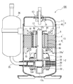
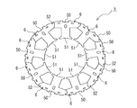
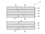
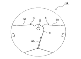
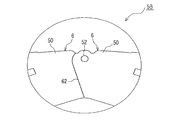
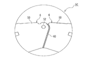
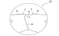
 図1は、本発明の実施の形態に係る固定子を備えた電動機を有する密閉型圧縮機の概略構成を示した縦断面図である。図2は、本発明の実施の形態に係る固定子の固定子鉄心を示した平面図である。図3は、本発明の実施の形態に係る固定子の固定子鉄心であって、第1鉄心シートが切り欠き部を有する部分を概略的に示した縦断面図である。図4は、本発明の実施の形態に係る固定子の固定子鉄心であって、第1鉄心シートが密着部を有する部分を概略的に示した縦断面図である。図1では、密閉型圧縮機100の一例としてシリンダ型ロータリ圧縮機を示している。この密閉型圧縮機100は、密閉容器1の内部に、冷媒ガスを圧縮する圧縮要素2と、圧縮要素2を駆動する電動要素3とが収納されている。
Embodiment.
FIG. 1 is a longitudinal sectional view showing a schematic configuration of a hermetic compressor having a motor provided with a stator according to an embodiment of the present invention. FIG. 2 is a plan view showing a stator core of a stator according to an embodiment of the present invention. FIG. 3 is a longitudinal cross-sectional view schematically showing a portion of a stator core of a stator according to an embodiment of the present invention, in which a first core sheet has a notch. FIG. 4 is a longitudinal cross-sectional view schematically showing a portion of the stator core of the stator according to the embodiment of the present invention, in which the first core sheet has the contact portion. In FIG. 1, a cylinder type rotary compressor is shown as an example of the hermetic type compressor 100. In the hermetic compressor 100, a compression element 2 for compressing a refrigerant gas and an electric element 3 for driving the compression element 2 are housed in the inside of the hermetic container 1.
 密閉容器1は、有底筒形状の下部容器10と、下部容器10の上部開口を密閉状態で覆う上部容器11とで構成されている。下部容器10の内部には、下側に圧縮要素2が設置され、上側に電動要素3が設置されている。圧縮要素2と電動要素3とは、クランクシャフト12によって連結され、電動要素3の回転運動が圧縮要素2に伝達される構成である。圧縮要素2は、伝達された回転力によって冷媒ガスを圧縮し、密閉容器1内に吐出する。つまり、密閉容器1内は、圧縮された高温・高圧の冷媒ガスによって満たされている。密閉容器1の下部、すなわち下部容器10の底部には、圧縮要素2を潤滑するための冷凍機油が貯留されている。 The closed container 1 is configured of a bottomed cylindrical lower container 10 and an upper container 11 that covers the upper opening of the lower container 10 in a sealed state. Inside the lower container 10, the compression element 2 is installed on the lower side, and the electric element 3 is installed on the upper side. The compression element 2 and the electric element 3 are connected by a crankshaft 12, and the rotational movement of the electric element 3 is transmitted to the compression element 2. The compression element 2 compresses the refrigerant gas by the transmitted rotational force and discharges it into the closed container 1. That is, the inside of the closed container 1 is filled with the compressed high-temperature and high-pressure refrigerant gas. In the lower part of the closed container 1, that is, at the bottom of the lower container 10, refrigeration oil for lubricating the compression element 2 is stored.
 圧縮要素2は、シリンダ20、ローリングピストン21、主軸受22、副軸受23、吐出マフラー24、及びベーン(図示は省略)等で構成されている。 The compression element 2 includes a cylinder 20, a rolling piston 21, a main bearing 22, a sub bearing 23, a discharge muffler 24, and vanes (not shown).
 シリンダ20は、内部に圧縮室と吸入室を有するシリンダ室を備えている。シリンダ20には、冷凍サイクルからの吸入ガスが吸入マフラー26を介して通る吸入連結管25が連結されている。シリンダ室は、軸方向両端が開口している。 The cylinder 20 is provided with a cylinder chamber having a compression chamber and a suction chamber inside. A suction connection pipe 25 through which suction gas from the refrigeration cycle passes through the suction muffler 26 is connected to the cylinder 20. The cylinder chamber is open at both axial ends.
 ローリングピストン21は、シリンダ室内を偏心回転するものである。ローリングピストン21はリング状であり、内周がクランクシャフト12の偏心軸部12aに摺動自在に嵌合している。つまり、圧縮要素2は、クランクシャフト12の偏心軸部12aに嵌合するローリングピストン21がシリンダ室内に収納され、シリンダ20に設けられた溝内を径方向に往復運動するベーンの一端がローリングピストン21の外周に当接しながら圧縮室を形成する構成である。 The rolling piston 21 rotates eccentrically in the cylinder chamber. The rolling piston 21 is ring-shaped, and the inner periphery thereof is slidably fitted to the eccentric shaft portion 12 a of the crankshaft 12. That is, in the compression element 2, the rolling piston 21 fitted in the eccentric shaft portion 12 a of the crankshaft 12 is housed in the cylinder chamber, and one end of the vane reciprocating in the radial direction in the groove provided in the cylinder 20 is the rolling piston The compression chamber is formed in contact with the outer circumference of the H.21.
 主軸受22は、クランクシャフト12の主軸部12bを摺動自在に嵌合するとともに、シリンダ20のシリンダ室の一方の開口を閉塞する。主軸受22には、吐出マフラー24が取り付けられている。主軸受22の吐出弁から吐出される高温・高圧の吐出ガスは、吐出マフラー24に入り、吐出マフラー24の吐出穴24aから密閉容器1内に放出される。副軸受23は、クランクシャフト12の副軸部12cを摺動自在に嵌合するとともに、シリンダ20のシリンダ室の他方の開口を閉塞する。 The main bearing 22 slidably fits the main shaft portion 12 b of the crankshaft 12 and closes one opening of the cylinder chamber of the cylinder 20. A discharge muffler 24 is attached to the main bearing 22. The high temperature / high pressure discharge gas discharged from the discharge valve of the main bearing 22 enters the discharge muffler 24 and is discharged into the closed container 1 from the discharge hole 24 a of the discharge muffler 24. The auxiliary bearing 23 slidably engages the auxiliary shaft portion 12 c of the crankshaft 12 and closes the other opening of the cylinder chamber of the cylinder 20.
 電動要素3は、円環状の固定子4と、固定子4の内側に回転自在に設けられた回転子8と、を備えた電動機である。電動要素3は、一例としてブラシレスDCモータで構成されている。 The electric element 3 is an electric motor including an annular stator 4 and a rotor 8 rotatably provided inside the stator 4. The electric element 3 is constituted by a brushless DC motor as an example.
 固定子4は、固定子鉄心5と、コイル7とで構成されている。固定子鉄心5は、図2に示すように、円環状のバックヨーク50部と、バックヨーク部50から内方に突出した複数のティース部51とを有している。固定子鉄心5は、図3及び図4に示すように、薄板の電磁鋼板を打ち抜き形成された第1鉄心シート5A及び第2鉄心シート5Bを交互に複数枚積層して形成されている。固定子鉄心5は、下部容器10の中間部分の内径よりも大きい外径で形成され、下部容器10の内面に焼嵌めによって固定されている。 The stator 4 is composed of a stator core 5 and a coil 7. As shown in FIG. 2, the stator core 5 has an annular back yoke 50 and a plurality of teeth 51 projecting inward from the back yoke 50. As shown in FIGS. 3 and 4, the stator core 5 is formed by alternately laminating a plurality of first core sheets 5A and second core sheets 5B formed by punching thin electromagnetic steel sheets. The stator core 5 is formed with an outer diameter larger than the inner diameter of the middle portion of the lower container 10, and is fixed to the inner surface of the lower container 10 by shrink fitting.
 第1鉄心シート5Aは、周方向に分割された複数のコア片6を有し、隣接するコア片6のバックヨーク部50の端部を突き合わせて円環状とした構成である。同様に、第2鉄心シート5Bも、周方向に分割された複数のコア片6を有し、隣接するコア片6のバックヨーク部50の端部を突き合わせて円環状とした構成である。第1鉄心シート5Aのコア片6と第2鉄心シート5Bのコア片6とは、回転軸部52によって回動自在に連結されている。 The first core sheet 5A has a plurality of core pieces 6 divided in the circumferential direction, and the end portions of the back yoke portions 50 of the adjacent core pieces 6 are butted to form an annular shape. Similarly, the second core sheet 5B also has a plurality of core pieces 6 divided in the circumferential direction, and the end portions of the back yoke portion 50 of the adjacent core pieces 6 are butted to form an annular shape. The core piece 6 of the first core sheet 5A and the core piece 6 of the second core sheet 5B are rotatably connected by the rotation shaft portion 52.
 図5は、本発明の実施の形態に係る固定子の第1鉄心シートの連結部分を示した要部拡大図である。図6は、本発明の実施の形態に係る固定子の第2鉄心シートの連結部分を示した要部拡大図である。第1鉄心シート5Aは、図5に示すように、隣接するバックヨーク部50の端部間に、内面側から径方向に向かって中間部まで隙間を形成する切り欠き部60と、中間部から外面側までバックヨーク部50の端部を突き合わせた密着部61と、を有している。一方、第2鉄心シート5Bは、図6に示すように、隣接するバックヨーク部50の端部を内面側から径方向に向かって外面側までを突き合わせた密着部62を有している。 FIG. 5: is the principal part enlarged view which showed the connection part of the 1st core sheet of the stator which concerns on embodiment of this invention. FIG. 6 is an enlarged view of an essential part showing a connecting part of the second core sheet of the stator according to the embodiment of the present invention. As shown in FIG. 5, the first core sheet 5A has a notch 60 between the end portions of the adjacent back yoke portions 50, which forms a gap from the inner surface side to the intermediate portion in the radial direction, and the intermediate portion And an adhesive portion 61 in which the end of the back yoke portion 50 is butted to the outer surface side. On the other hand, as shown in FIG. 6, the second core sheet 5B has a close contact portion 62 in which the end portion of the adjacent back yoke portion 50 is butted from the inner surface side to the outer surface side in the radial direction.
 切り欠き部60を設けた部分である内面側から径方向に向かって中間部までは、密閉容器1に固定子4を焼嵌めしたときに、固定子4の内部で磁束が集中する部分である。一方、密着部61を設けた部分である中間部から外面側までは、密閉容器1に固定子4を焼嵌めしたときに、固定子4の内部で磁束が集中しない部分である。因みに、磁束が集中しない部分とは、例えば固定子4の外面側から径方向に向かって約2mmまでの範囲である。また、磁束が集中する部分とは、例えば固定子4の外面側から径方向に向かって約2mmを超えた位置から内面側までの範囲である。 From the inner surface side where the notched portion 60 is provided to the intermediate portion in the radial direction from the inner surface side, when the stator 4 is shrink fitted to the closed container 1, the magnetic flux is concentrated inside the stator 4 . On the other hand, when the stator 4 is shrink-fit to the closed container 1 from the middle part to the outer surface side where the close contact part 61 is provided, the magnetic flux is not concentrated inside the stator 4. Incidentally, the portion where the magnetic flux is not concentrated is, for example, in the range of about 2 mm in the radial direction from the outer surface side of the stator 4. Further, the portion where the magnetic flux is concentrated is, for example, a range from a position exceeding about 2 mm in the radial direction from the outer surface side of the stator 4 to the inner surface side.
 コイル7は、絶縁部材70を介して固定子鉄心5のティース部51に巻回されている。コイル7には、図1に示すように、電圧をかけて電流を流すためのリード線71が接続されている。リード線71は、上部容器11に設けられたガラス端子13に接続され、密閉容器1の外部から電力の供給を受ける。 The coil 7 is wound around the teeth portion 51 of the stator core 5 via the insulating member 70. As shown in FIG. 1, a lead wire 71 for applying a voltage and causing a current to flow is connected to the coil 7. The lead wire 71 is connected to the glass terminal 13 provided in the upper case 11 and receives supply of power from the outside of the closed case 1.
 回転子8は、回転子鉄心80と、永久磁石81と、上バランスウエイト82と、下バランスウエイト83と、リベット84とを備えている。回転子鉄心80は、薄板電磁鋼板を打ち抜き形成された鉄心シートを複数積層して構成されている。永久磁石81は、回転子鉄心80に形成された磁石挿入孔に挿入されている。 The rotor 8 includes a rotor core 80, a permanent magnet 81, an upper balance weight 82, a lower balance weight 83, and a rivet 84. The rotor core 80 is configured by laminating a plurality of core sheets formed by punching thin electromagnetic steel sheets. The permanent magnet 81 is inserted into a magnet insertion hole formed in the rotor core 80.
 上バランスウエイト82は、回転子鉄心80の上端部に配置されている。下バランスウエイト83は、回転子鉄心80の下端部に配置される。上バランスウエイト82及び下バランスウエイト83は、圧縮要素2の冷媒ガスの吸入、圧縮及び吐出などの圧縮工程における回転トルクの変位によって生じる回転子8の回転運動のむらを修正するために設けられている。また、上バランスウエイト82及び下バランスウエイト83は、永久磁石81の飛散を防止する端板の役割も兼ねている。上バランスウエイト82及び下バランスウエイト83と端板は別部品でもよい。 The upper balance weight 82 is disposed at the upper end of the rotor core 80. The lower balance weight 83 is disposed at the lower end of the rotor core 80. The upper balance weight 82 and the lower balance weight 83 are provided to correct the unevenness of the rotational movement of the rotor 8 caused by the displacement of the rotational torque in the compression process such as suction, compression and discharge of the refrigerant gas of the compression element 2 . The upper balance weight 82 and the lower balance weight 83 also serve as an end plate that prevents the permanent magnet 81 from scattering. The upper balance weight 82, the lower balance weight 83 and the end plate may be separate parts.
 リベット84は、上バランスウエイト82、下バランスウエイト83及び回転子鉄心80を固定するものである。 The rivets 84 fix the upper balance weight 82, the lower balance weight 83 and the rotor core 80.
 図7は、従来の固定子鉄心であって、第1鉄心シートの連結部分を示した要部拡大図である。図8は、従来の固定子鉄心であって、第2鉄心シートの連結部分を示した要部拡大図である。従来の固定子鉄心も、円環状のバックヨーク部50と、バックヨーク部50から内方に突出した複数のティース部51と、を有している。固定子鉄心は、円環状の第1鉄心シート5Cと円環状の第2鉄心シート5Dとを交互に複数枚積層して形成されている。 FIG. 7 is an enlarged view of a main part of a conventional stator core, showing a connection portion of a first core sheet. FIG. 8 is an enlarged view of a main part of a conventional stator core, showing a connecting portion of a second core sheet. The conventional stator core also has an annular back yoke portion 50 and a plurality of teeth portions 51 projecting inward from the back yoke portion 50. The stator core is formed by alternately laminating a plurality of annular first core sheet 5C and an annular second core sheet 5D.
 第1鉄心シート5Cと第2鉄心シート5Dは、それぞれ周方向に分割された複数のコア片6を有し、隣接するコア片6のバックヨーク部50の端部を突き合わせて円環状とした構成である。第1鉄心シート5Cは、図7に示すように、隣接するバックヨーク部50の端部間に、内面側から径方向に向かって外面側まで隙間63を有している。第2鉄心シート5Dは、図8に示すように、隣接するバックヨーク部50の端部を内面側から径方向に向かって外面側までを突き合わせた密着部64を有している。 The first core sheet 5C and the second core sheet 5D each have a plurality of core pieces 6 divided in the circumferential direction, and the end portions of the back yoke portions 50 of the adjacent core pieces 6 are butted to form an annular shape. It is. As shown in FIG. 7, the first core sheet 5C has a gap 63 between the end portions of the adjacent back yoke portions 50 from the inner surface side to the outer surface side in the radial direction. As shown in FIG. 8, the second core sheet 5D has a close contact portion 64 in which the end portions of the adjacent back yoke portions 50 are butted from the inner surface side to the outer surface side in the radial direction.
 図7及び図8に示した固定子鉄心を備えた固定子は、第1鉄心シート5Cに隙間63を設けているので、固定子の外面を密閉容器1の内面に焼嵌めする時に、バックヨーク部50の端部同士が突き当たって、応力が増加する事態を抑制でき、鉄損を低減させることができる。しかし、図7及び図8に示した従来の固定子鉄心を備えた固定子のように、内面側から径方向に向かって外面部まで隙間63を設けてしまうと、鉄損を低減することはできるが、固定子の剛性が低下する虞がある。そのため、固定子と密閉容器1との締結力が低下し、密閉型圧縮機の騒音が増加する虞がある。 Since the stator provided with the stator core shown in FIGS. 7 and 8 has the gap 63 in the first core sheet 5C, when the outer surface of the stator is shrink-fit to the inner surface of the sealed container 1, the back yoke It is possible to suppress an increase in stress due to the end portions of the portion 50 hitting each other and to reduce iron loss. However, as in the stator provided with the conventional stator core shown in FIGS. 7 and 8, if the gap 63 is provided from the inner surface side to the outer surface portion in the radial direction, iron loss can not be reduced. However, the rigidity of the stator may be reduced. Therefore, the fastening force between the stator and the hermetic container 1 may be reduced, and the noise of the hermetic compressor may be increased.
 一方、本実施の形態に係る固定子4は、第1鉄心シート5Aにおいて磁束が集中する部分である内面側から径方向に向かって中間部までを切り欠き部60としているので、密閉容器1の内面に焼嵌めした際に、切り欠き部60で応力を抑制でき、鉄損を抑制できる。また、固定子4は、第1鉄心シート5Aに切り欠き部60を設けることによって、外径を収縮させて密着部61の応力を増加させることができるので、密着部61の剛性を増加させることができる。この剛性の増加に伴って、ヤング率が増加するので、密閉容器1への締結力を増加させることができ、密閉型圧縮機100の騒音を抑制することができる。また、固定子4は、内部で磁束が集中しない部分である中間部から外面側に密着部61を設けているので、焼嵌めした際に密着部61に応力が発生しても、当該応力による電磁鋼板の磁気特性の劣化を抑制でき、鉄損を抑制できる。更に、固定子4は、第2鉄心シート5Bが隣接するバックヨーク部50の端部を内面側から径方向に向かって外面側までを突き合わせた密着部62を有しているので、積層方向の剛性を高めつつ、内径側の真円度を高めることができ、構造の安定化を図ることができる。 On the other hand, the stator 4 according to the present embodiment has the notch 60 from the inner surface side where the magnetic flux concentrates in the first core sheet 5A to the intermediate portion in the radial direction from the inner surface side. When the heat-shrinkage is performed on the inner surface, the stress can be suppressed by the notches 60, and the iron loss can be suppressed. Further, by providing the notch portion 60 in the first core sheet 5A, the stator 4 can contract the outer diameter and increase the stress of the adhesion portion 61, thereby increasing the rigidity of the adhesion portion 61. Can. Since the Young's modulus increases with the increase in rigidity, the fastening force to the closed container 1 can be increased, and the noise of the closed compressor 100 can be suppressed. Further, the stator 4 is provided with the close contact portion 61 from the intermediate portion which is the portion where magnetic flux is not concentrated inside to the outer surface side. Therefore, even if stress occurs in the close contact portion 61 when shrink fitting is performed, the stress Deterioration of the magnetic properties of the magnetic steel sheet can be suppressed, and iron loss can be suppressed. Furthermore, since the stator 4 has the adhesion portion 62 in which the end portion of the back yoke portion 50 adjacent to the second core sheet 5B is butted from the inner surface side to the outer surface side in the radial direction, While improving the rigidity, the roundness on the inner diameter side can be increased, and the structure can be stabilized.
 また、本実施の形態に係る固定子4では、固定子鉄心5が第1鉄心シート5Aと第2鉄心シート5Bを交互に複数枚積層して形成することによって、第1鉄心シート5Aの上記作用効果と第2鉄心シート5Bの上記作用効果とをバランス良く効果的に発揮することができる。 Further, in the stator 4 according to the present embodiment, the stator core 5 is formed by alternately laminating the first core sheet 5A and the second core sheet 5B, thereby the above-described action of the first core sheet 5A. The effects and the above-described effects of the second core sheet 5B can be effectively exhibited in a well-balanced manner.
 以上に本発明を実施の形態に基づいて説明したが、本発明は上述した実施の形態の構成に限定されるものではない。例えば、密閉型圧縮機100は、一例としてシリンダ型ロータリ圧縮機を示したが、他の構造の圧縮機でもよい。また、密閉型圧縮機100は、図示した構成に限定されず、他の構成要素を含んだものでよい。また、固定子鉄心5は、第1鉄心シート5Aと第2鉄心シート5Bを交互に複数枚積層して形成された構成を示したが、これに限定されない。例えば第1鉄心シート5Aを2枚配置するごとに第2鉄心シート5Bを1枚配置する等した構成でもよい。要するに、いわゆる当業者が必要に応じてなす種々なる変更、応用、利用の範囲をも本発明の要旨(技術的範囲)に含むことを念のため申し添える。 Although the present invention has been described above based on the embodiment, the present invention is not limited to the configuration of the embodiment described above. For example, although the hermetic compressor 100 has shown a cylinder type rotary compressor as an example, it may be a compressor of other structure. In addition, the hermetic compressor 100 is not limited to the illustrated configuration, and may include other components. Moreover, although the stator core 5 showed the structure formed by laminating | stacking multiple sheets of the 1st core sheet 5A and the 2nd core sheet 5B alternately, it was not limited to this. For example, the configuration may be such that one second core sheet 5B is disposed every time two first core sheets 5A are disposed. In short, the scope of the various modifications, applications, and uses that the so-called person skilled in the art makes as needed is mentioned in the scope of the present invention (the technical scope).
 1 密閉容器、2 圧縮要素、3 電動要素(電動機)、4 固定子、5 固定子鉄心、5A、5C 第1鉄心シート、5B、5D 第2鉄心シート、6 コア片、7 コイル、8 回転子、10 下部容器、11 上部容器、12 クランクシャフト、12a 偏心軸部、12b 主軸部、12c 副軸部、13 ガラス端子、20 シリンダ、21 ローリングピストン、22 主軸受、23 副軸受、24 吐出マフラー、24a 吐出穴、25 吸入連結管、26 吸入マフラー、50 バックヨーク部、51 ティース部、52 回転軸部、60 切り欠き部、61、62 密着部、63 隙間、64 密着部、70 絶縁部材、71 リード線、80 回転子鉄心、81 永久磁石、82 上バランスウエイト、83 下バランスウエイト、84 リベット、100 密閉型圧縮機。 DESCRIPTION OF SYMBOLS 1 sealed container, 2 compression element, 3 electric element (motor), 4 stator, 5 stator core, 5A, 5C 1st core sheet, 5B, 5D 2nd core sheet, 6 core pieces, 7 coils, 8 rotor , 10 lower container, 11 upper container, 12 crankshaft, 12a eccentric shaft, 12b main shaft, 12c countershaft, 13 glass terminals, 20 cylinders, 21 rolling pistons, 22 main bearings, 23 auxiliary bearings, 24 discharge muffler, 24a discharge hole, 25 suction connection pipe, 26 suction muffler, 50 back yoke portion, 51 teeth portion, 52 rotation shaft portion, 60 notches, 61, 62 close contact portion, 63 gap, 64 close contact portion, 70 insulating member, 71 Lead wire, 80 rotor core, 81 permanent magnets, 82 upper balance weights, 83 lower roses Suueito, 84 rivets, 100 hermetic compressor.

Claims (3)

  1.  円環状のバックヨーク部と、前記バックヨーク部から内方に突出した複数のティース部と、を有する固定子鉄心と、
     前記固定子鉄心のティース部に巻回されるコイルと、を備え、
     前記固定子鉄心は、円環状の第1鉄心シートと円環状の第2鉄心シートとを複数枚積層して形成されており、
     前記第1鉄心シートと前記第2鉄心シートは、それぞれ周方向に分割された複数のコア片を有し、隣接する前記コア片の前記バックヨーク部の端部を突き合わせて円環状とされており、
     前記第1鉄心シートは、隣接する前記バックヨーク部の端部間に、内面側から径方向に向かって中間部まで隙間を形成する切り欠き部と、当該中間部から外面側まで前記バックヨーク部の端部を突き合わせた密着部と、を有し、
     前記第2鉄心シートは、隣接する前記バックヨーク部の端部を内面側から径方向に向かって外面側までを突き合わせた密着部を有する、固定子。
    A stator core having an annular back yoke portion and a plurality of teeth portions projecting inward from the back yoke portion;
    And a coil wound around the teeth of the stator core,
    The stator core is formed by laminating a plurality of annular first core sheet and an annular second core sheet.
    The first core sheet and the second core sheet each have a plurality of core pieces divided in the circumferential direction, and end portions of the back yoke portions of the adjacent core pieces are butted to form an annular shape. ,
    The first core sheet includes a notch portion between the end portions of the adjacent back yoke portions to form a gap from the inner surface side to the intermediate portion in the radial direction, and the back yoke portion from the intermediate portion to the outer surface side And a close contact portion where the ends of the
    The second core sheet includes a contact portion in which the end portions of the adjacent back yoke portions are butted from the inner surface side to the outer surface side in the radial direction.
  2.  前記固定子鉄心は、前記第1鉄心シートと前記第2鉄心シートを交互に複数枚積層して形成されている、請求項1に記載の固定子。 The stator according to claim 1, wherein the stator core is formed by alternately laminating a plurality of the first core sheet and the second core sheet.
  3.  請求項1又は2に記載の固定子と、前記固定子の内側に回転自在に設けられた回転子と、を備えた電動機。 An electric motor comprising the stator according to claim 1 and a rotor rotatably provided inside the stator.
PCT/JP2017/045525 2017-12-19 2017-12-19 Stator and electric motor provided with stator WO2019123531A1 (en)

Priority Applications (5)

Application Number Priority Date Filing Date Title
JP2019559895A JPWO2019123531A1 (en) 2017-12-19 2017-12-19 Stator and electric motor equipped with the stator
CN201780096540.6A CN111492560A (en) 2017-12-19 2017-12-19 Stator and motor having the same
CZ2020-314A CZ2020314A3 (en) 2017-12-19 2017-12-19 A stator and an electric motor containing this stator
KR1020207015192A KR20200081427A (en) 2017-12-19 2017-12-19 Stator and electric motor having the stator
PCT/JP2017/045525 WO2019123531A1 (en) 2017-12-19 2017-12-19 Stator and electric motor provided with stator

Applications Claiming Priority (1)

Application Number Priority Date Filing Date Title
PCT/JP2017/045525 WO2019123531A1 (en) 2017-12-19 2017-12-19 Stator and electric motor provided with stator

Publications (1)

Publication Number Publication Date
WO2019123531A1 true WO2019123531A1 (en) 2019-06-27

Family

ID=66994478

Family Applications (1)

Application Number Title Priority Date Filing Date
PCT/JP2017/045525 WO2019123531A1 (en) 2017-12-19 2017-12-19 Stator and electric motor provided with stator

Country Status (5)

Country Link
JP (1) JPWO2019123531A1 (en)
KR (1) KR20200081427A (en)
CN (1) CN111492560A (en)
CZ (1) CZ2020314A3 (en)
WO (1) WO2019123531A1 (en)

Families Citing this family (1)

* Cited by examiner, † Cited by third party
Publication number Priority date Publication date Assignee Title
CN114142633B (en) * 2021-12-03 2023-01-06 广东美芝制冷设备有限公司 Stator, motor, compressor and refrigeration plant

Citations (4)

* Cited by examiner, † Cited by third party
Publication number Priority date Publication date Assignee Title
WO2007141907A1 (en) * 2006-06-05 2007-12-13 Mitsubishi Electric Corporation Split type iron core and its manufacturing method, and stator iron core
JP2011254625A (en) * 2010-06-02 2011-12-15 Aisin Seiki Co Ltd Rotary electric machine
JP2012029458A (en) * 2010-07-23 2012-02-09 Jfe Steel Corp Motor
JP2013042620A (en) * 2011-08-18 2013-02-28 Hitachi Automotive Systems Ltd Rotary electric machine

Family Cites Families (4)

* Cited by examiner, † Cited by third party
Publication number Priority date Publication date Assignee Title
CN102916504A (en) * 2006-10-13 2013-02-06 株式会社三井高科技 Laminated core and method for manufacturing the same
JP4998450B2 (en) * 2008-12-09 2012-08-15 トヨタ自動車株式会社 Stator manufacturing method
JP5174794B2 (en) * 2009-12-04 2013-04-03 三菱電機株式会社 Stator core and stator, electric motor and compressor
US10804754B2 (en) * 2015-08-21 2020-10-13 Mitsubishi Electric Corporation Permanent magnet embedded motor, compressor, and refrigerating and air conditioning apparatus

Patent Citations (4)

* Cited by examiner, † Cited by third party
Publication number Priority date Publication date Assignee Title
WO2007141907A1 (en) * 2006-06-05 2007-12-13 Mitsubishi Electric Corporation Split type iron core and its manufacturing method, and stator iron core
JP2011254625A (en) * 2010-06-02 2011-12-15 Aisin Seiki Co Ltd Rotary electric machine
JP2012029458A (en) * 2010-07-23 2012-02-09 Jfe Steel Corp Motor
JP2013042620A (en) * 2011-08-18 2013-02-28 Hitachi Automotive Systems Ltd Rotary electric machine

Also Published As

Publication number Publication date
CZ2020314A3 (en) 2020-07-29
CN111492560A (en) 2020-08-04
JPWO2019123531A1 (en) 2020-08-06
KR20200081427A (en) 2020-07-07

Similar Documents

Publication Publication Date Title
US6582207B2 (en) Motor compressor and cooling apparatus using the same
JP6377128B2 (en) Manufacturing method of rotor
JP5303833B2 (en) Motor rotor, motor and compressor
EP2268983B1 (en) Motor for compressor and hermetic compressor having the same
WO2017110476A1 (en) Compressor motor and compressor equipped with same
JP2011055576A (en) Compressor
WO2010016583A1 (en) Stator, motor, and compressor
JP2006183474A (en) Enclosed electric compressor and refrigeration cycle device
KR20110123145A (en) Hermetic compressor and manufacturing method thereof
JP5061576B2 (en) Axial gap type motor and compressor using the same
WO2019123531A1 (en) Stator and electric motor provided with stator
WO2018173877A1 (en) Compressor
WO2016076103A1 (en) Motor rotor, motor using same, and electric compressor
JP5672325B2 (en) Method for assembling rotor for motor, motor and compressor
JP6509524B2 (en) Motor rotor, motor using the same, and electric compressor
JP2010041851A (en) Structure of fixing stator and casing, and compressor equipped with the same
JP6151324B2 (en) Hermetic electric compressor
EP3163083B1 (en) Electric compressor
WO2019021658A1 (en) Compressor
JP6393077B2 (en) Hermetic electric compressor
JP2004274995A (en) Permanent magnet rotating electric machine and compressor using the same
JP2010081735A (en) Stator, motor and compressor
KR101932049B1 (en) Motor and compressor having this
WO2014167807A1 (en) Induction synchronous motor
JP2012124988A (en) Motor and compressor

Legal Events

Date Code Title Description
121 Ep: the epo has been informed by wipo that ep was designated in this application

Ref document number: 17935105

Country of ref document: EP

Kind code of ref document: A1

ENP Entry into the national phase

Ref document number: 2019559895

Country of ref document: JP

Kind code of ref document: A

ENP Entry into the national phase

Ref document number: 20207015192

Country of ref document: KR

Kind code of ref document: A

NENP Non-entry into the national phase

Ref country code: DE

122 Ep: pct application non-entry in european phase

Ref document number: 17935105

Country of ref document: EP

Kind code of ref document: A1