WO2019123531A1 - 固定子及びその固定子を備えた電動機 - Google Patents
固定子及びその固定子を備えた電動機 Download PDFInfo
- Publication number
- WO2019123531A1 WO2019123531A1 PCT/JP2017/045525 JP2017045525W WO2019123531A1 WO 2019123531 A1 WO2019123531 A1 WO 2019123531A1 JP 2017045525 W JP2017045525 W JP 2017045525W WO 2019123531 A1 WO2019123531 A1 WO 2019123531A1
- Authority
- WO
- WIPO (PCT)
- Prior art keywords
- stator
- core
- surface side
- back yoke
- core sheet
- Prior art date
Links
Images

Classifications
-
- H—ELECTRICITY
- H02—GENERATION; CONVERSION OR DISTRIBUTION OF ELECTRIC POWER
- H02K—DYNAMO-ELECTRIC MACHINES
- H02K1/00—Details of the magnetic circuit
- H02K1/06—Details of the magnetic circuit characterised by the shape, form or construction
- H02K1/12—Stationary parts of the magnetic circuit
- H02K1/14—Stator cores with salient poles
-
- H—ELECTRICITY
- H02—GENERATION; CONVERSION OR DISTRIBUTION OF ELECTRIC POWER
- H02K—DYNAMO-ELECTRIC MACHINES
- H02K1/00—Details of the magnetic circuit
- H02K1/06—Details of the magnetic circuit characterised by the shape, form or construction
- H02K1/12—Stationary parts of the magnetic circuit
- H02K1/16—Stator cores with slots for windings
Definitions
- the present invention relates to a stator and a motor provided with the stator.
- an electric motor used for a compressor or the like is configured of an annular stator and a rotor rotatably provided inside the stator.
- the stator includes a stator core having an annular back yoke portion and a plurality of teeth portions projecting inward from the back yoke portion, and a coil wound around the teeth portion of the stator core.
- the stator core is formed by laminating a plurality of annular core sheets.
- the core sheet has a plurality of core pieces divided in the circumferential direction, and the end portions of the back yoke portions of the adjacent core pieces are abutted into an annular shape.
- the stator is held by shrink fitting on the inner surface of the closed vessel forming the shell of the compressor when the motor is incorporated into the compressor.
- the stator has a configuration in which the end portions of adjacent back yoke portions are brought into close contact from the inner surface side to the outer surface side from the inner surface side to the outer surface side, when shrink fitting is performed on the inner surface of the sealed container, When the end portions abut each other, stress may increase and iron loss may increase.
- the stator when the stator is provided with a gap from the inner surface side to the outer surface side in the radial direction between the end portions of the adjacent back yoke portions, the end of the back yoke portion is shrink-fitted to the inner surface of the sealed container. Since it can control that parts collide, iron loss can be controlled. However, if the stator is provided with a gap from the inner surface side to the outer surface side in the radial direction, the rigidity is reduced, so the fastening force with the closed container is reduced, which may increase the noise of the compressor.
- the fastening force refers to the removal load and the holding torque.
- the present invention has been made to solve the above-mentioned problems, and it is desirable to suppress an increase in iron loss caused by the end portions of the back yoke portion hitting against each other when shrink-fitting on the inner surface of the sealed container. It is an object of the present invention to provide a stator and an electric motor provided with the stator that can reduce the rigidity and prevent an increase in the noise of the compressor.
- the stator according to the present invention is wound around a stator iron core having an annular back yoke portion and a plurality of teeth portions protruding inward from the back yoke portion, and the teeth portion of the stator iron core
- the stator core is formed by laminating a plurality of annular first core sheet and an annular second core sheet, and the first core sheet and the second core are formed.
- the sheet has a plurality of core pieces divided in the circumferential direction, and the ends of the back yoke portions of the adjacent core pieces are abutted to form an annular shape, and the first core sheets are adjacent to each other.
- a notch portion forming a gap from the inner surface side to the intermediate portion in the radial direction from the inner surface side, and a close contact portion in which the end portion of the back yoke portion abuts from the intermediate portion to the outer surface side
- the second iron core DOO are those having contact portions which butt to the outer surface side end portion of the back yoke portion adjacent toward the inner side in the radial direction.
- the first core sheet particularly from the inner surface side where the magnetic flux concentrates to the intermediate portion in the radial direction from the inner surface side to the intermediate portion is a cutaway portion, when the stator is shrink fitted to the inner surface of the sealed container.
- stress can be suppressed at the notched portion, and iron loss can be suppressed.
- the outer diameter can be shrunk to increase the stress of the contact portion, so that the rigidity of the contact portion can be increased. Since the Young's modulus increases with the increase of the rigidity, the fastening force between the stator and the closed container can be increased, and the noise of the compressor can be suppressed.
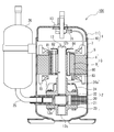
- FIG. 1 is a longitudinal sectional view showing a schematic configuration of a hermetic compressor having a motor provided with a stator according to an embodiment of the present invention.
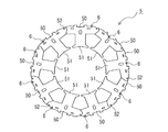
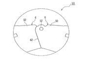
- FIG. 2 is a plan view showing a stator core of a stator according to an embodiment of the present invention.
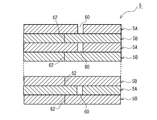
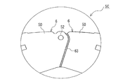
- FIG. 3 is a longitudinal cross-sectional view schematically showing a portion of a stator core of a stator according to an embodiment of the present invention, in which a first core sheet has a notch.
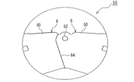
- FIG. 4 is a longitudinal cross-sectional view schematically showing a portion of the stator core of the stator according to the embodiment of the present invention, in which the first core sheet has the contact portion.
- FIG. 1 is a longitudinal sectional view showing a schematic configuration of a hermetic compressor having a motor provided with a stator according to an embodiment of the present invention.
- FIG. 2 is a plan view showing a stator core of a stator according to an embodiment of the present invention.
- FIG. 3 is a
- a cylinder type rotary compressor is shown as an example of the hermetic type compressor 100.
- a compression element 2 for compressing a refrigerant gas and an electric element 3 for driving the compression element 2 are housed in the inside of the hermetic container 1.
- the closed container 1 is configured of a bottomed cylindrical lower container 10 and an upper container 11 that covers the upper opening of the lower container 10 in a sealed state.
- the compression element 2 is installed on the lower side, and the electric element 3 is installed on the upper side.
- the compression element 2 and the electric element 3 are connected by a crankshaft 12, and the rotational movement of the electric element 3 is transmitted to the compression element 2.
- the compression element 2 compresses the refrigerant gas by the transmitted rotational force and discharges it into the closed container 1. That is, the inside of the closed container 1 is filled with the compressed high-temperature and high-pressure refrigerant gas.
- refrigeration oil for lubricating the compression element 2 is stored in the lower part of the closed container 1, that is, at the bottom of the lower container 10.
- the compression element 2 includes a cylinder 20, a rolling piston 21, a main bearing 22, a sub bearing 23, a discharge muffler 24, and vanes (not shown).
- the cylinder 20 is provided with a cylinder chamber having a compression chamber and a suction chamber inside.
- a suction connection pipe 25 through which suction gas from the refrigeration cycle passes through the suction muffler 26 is connected to the cylinder 20.
- the cylinder chamber is open at both axial ends.
- the rolling piston 21 rotates eccentrically in the cylinder chamber.
- the rolling piston 21 is ring-shaped, and the inner periphery thereof is slidably fitted to the eccentric shaft portion 12 a of the crankshaft 12. That is, in the compression element 2, the rolling piston 21 fitted in the eccentric shaft portion 12 a of the crankshaft 12 is housed in the cylinder chamber, and one end of the vane reciprocating in the radial direction in the groove provided in the cylinder 20 is the rolling piston
- the compression chamber is formed in contact with the outer circumference of the H.21.
- the main bearing 22 slidably fits the main shaft portion 12 b of the crankshaft 12 and closes one opening of the cylinder chamber of the cylinder 20.
- a discharge muffler 24 is attached to the main bearing 22.
- the high temperature / high pressure discharge gas discharged from the discharge valve of the main bearing 22 enters the discharge muffler 24 and is discharged into the closed container 1 from the discharge hole 24 a of the discharge muffler 24.
- the auxiliary bearing 23 slidably engages the auxiliary shaft portion 12 c of the crankshaft 12 and closes the other opening of the cylinder chamber of the cylinder 20.
- the electric element 3 is an electric motor including an annular stator 4 and a rotor 8 rotatably provided inside the stator 4.
- the electric element 3 is constituted by a brushless DC motor as an example.
- the stator 4 is composed of a stator core 5 and a coil 7. As shown in FIG. 2, the stator core 5 has an annular back yoke 50 and a plurality of teeth 51 projecting inward from the back yoke 50. As shown in FIGS. 3 and 4, the stator core 5 is formed by alternately laminating a plurality of first core sheets 5A and second core sheets 5B formed by punching thin electromagnetic steel sheets. The stator core 5 is formed with an outer diameter larger than the inner diameter of the middle portion of the lower container 10, and is fixed to the inner surface of the lower container 10 by shrink fitting.
- the first core sheet 5A has a plurality of core pieces 6 divided in the circumferential direction, and the end portions of the back yoke portions 50 of the adjacent core pieces 6 are butted to form an annular shape.
- the second core sheet 5B also has a plurality of core pieces 6 divided in the circumferential direction, and the end portions of the back yoke portion 50 of the adjacent core pieces 6 are butted to form an annular shape.
- the core piece 6 of the first core sheet 5A and the core piece 6 of the second core sheet 5B are rotatably connected by the rotation shaft portion 52.
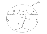
- FIG. 5 is the principal part enlarged view which showed the connection part of the 1st core sheet of the stator which concerns on embodiment of this invention.
- FIG. 6 is an enlarged view of an essential part showing a connecting part of the second core sheet of the stator according to the embodiment of the present invention.
- the first core sheet 5A has a notch 60 between the end portions of the adjacent back yoke portions 50, which forms a gap from the inner surface side to the intermediate portion in the radial direction, and the intermediate portion And an adhesive portion 61 in which the end of the back yoke portion 50 is butted to the outer surface side.
- the second core sheet 5B has a close contact portion 62 in which the end portion of the adjacent back yoke portion 50 is butted from the inner surface side to the outer surface side in the radial direction.
- the stator 4 is shrink fitted to the closed container 1 from the middle part to the outer surface side where the close contact part 61 is provided, the magnetic flux is not concentrated inside the stator 4.
- the portion where the magnetic flux is not concentrated is, for example, in the range of about 2 mm in the radial direction from the outer surface side of the stator 4.
- the portion where the magnetic flux is concentrated is, for example, a range from a position exceeding about 2 mm in the radial direction from the outer surface side of the stator 4 to the inner surface side.
- the coil 7 is wound around the teeth portion 51 of the stator core 5 via the insulating member 70.
- a lead wire 71 for applying a voltage and causing a current to flow is connected to the coil 7.
- the lead wire 71 is connected to the glass terminal 13 provided in the upper case 11 and receives supply of power from the outside of the closed case 1.
- the rotor 8 includes a rotor core 80, a permanent magnet 81, an upper balance weight 82, a lower balance weight 83, and a rivet 84.
- the rotor core 80 is configured by laminating a plurality of core sheets formed by punching thin electromagnetic steel sheets.
- the permanent magnet 81 is inserted into a magnet insertion hole formed in the rotor core 80.
- the upper balance weight 82 is disposed at the upper end of the rotor core 80.
- the lower balance weight 83 is disposed at the lower end of the rotor core 80.
- the upper balance weight 82 and the lower balance weight 83 are provided to correct the unevenness of the rotational movement of the rotor 8 caused by the displacement of the rotational torque in the compression process such as suction, compression and discharge of the refrigerant gas of the compression element 2 .
- the upper balance weight 82 and the lower balance weight 83 also serve as an end plate that prevents the permanent magnet 81 from scattering.
- the upper balance weight 82, the lower balance weight 83 and the end plate may be separate parts.
- the rivets 84 fix the upper balance weight 82, the lower balance weight 83 and the rotor core 80.
- FIG. 7 is an enlarged view of a main part of a conventional stator core, showing a connection portion of a first core sheet.
- FIG. 8 is an enlarged view of a main part of a conventional stator core, showing a connecting portion of a second core sheet.
- the conventional stator core also has an annular back yoke portion 50 and a plurality of teeth portions 51 projecting inward from the back yoke portion 50.
- the stator core is formed by alternately laminating a plurality of annular first core sheet 5C and an annular second core sheet 5D.
- the first core sheet 5C and the second core sheet 5D each have a plurality of core pieces 6 divided in the circumferential direction, and the end portions of the back yoke portions 50 of the adjacent core pieces 6 are butted to form an annular shape. It is. As shown in FIG. 7, the first core sheet 5C has a gap 63 between the end portions of the adjacent back yoke portions 50 from the inner surface side to the outer surface side in the radial direction. As shown in FIG. 8, the second core sheet 5D has a close contact portion 64 in which the end portions of the adjacent back yoke portions 50 are butted from the inner surface side to the outer surface side in the radial direction.
- stator provided with the stator core shown in FIGS. 7 and 8 has the gap 63 in the first core sheet 5C, when the outer surface of the stator is shrink-fit to the inner surface of the sealed container 1, the back yoke It is possible to suppress an increase in stress due to the end portions of the portion 50 hitting each other and to reduce iron loss.
- the stator provided with the conventional stator core shown in FIGS. 7 and 8 if the gap 63 is provided from the inner surface side to the outer surface portion in the radial direction, iron loss can not be reduced.
- the rigidity of the stator may be reduced. Therefore, the fastening force between the stator and the hermetic container 1 may be reduced, and the noise of the hermetic compressor may be increased.
- the stator 4 has the notch 60 from the inner surface side where the magnetic flux concentrates in the first core sheet 5A to the intermediate portion in the radial direction from the inner surface side.
- the stress can be suppressed by the notches 60, and the iron loss can be suppressed.
- the stator 4 can contract the outer diameter and increase the stress of the adhesion portion 61, thereby increasing the rigidity of the adhesion portion 61.
- the Young's modulus increases with the increase in rigidity, the fastening force to the closed container 1 can be increased, and the noise of the closed compressor 100 can be suppressed.
- stator 4 is provided with the close contact portion 61 from the intermediate portion which is the portion where magnetic flux is not concentrated inside to the outer surface side. Therefore, even if stress occurs in the close contact portion 61 when shrink fitting is performed, the stress Deterioration of the magnetic properties of the magnetic steel sheet can be suppressed, and iron loss can be suppressed. Furthermore, since the stator 4 has the adhesion portion 62 in which the end portion of the back yoke portion 50 adjacent to the second core sheet 5B is butted from the inner surface side to the outer surface side in the radial direction, While improving the rigidity, the roundness on the inner diameter side can be increased, and the structure can be stabilized.
- the stator core 5 is formed by alternately laminating the first core sheet 5A and the second core sheet 5B, thereby the above-described action of the first core sheet 5A.
- the effects and the above-described effects of the second core sheet 5B can be effectively exhibited in a well-balanced manner.
- the present invention has been described above based on the embodiment, the present invention is not limited to the configuration of the embodiment described above.
- the hermetic compressor 100 has shown a cylinder type rotary compressor as an example, it may be a compressor of other structure.
- the hermetic compressor 100 is not limited to the illustrated configuration, and may include other components.
- the stator core 5 showed the structure formed by laminating
- the configuration may be such that one second core sheet 5B is disposed every time two first core sheets 5A are disposed.
Landscapes
- Engineering & Computer Science (AREA)
- Power Engineering (AREA)
- Iron Core Of Rotating Electric Machines (AREA)
Abstract
Description
図1は、本発明の実施の形態に係る固定子を備えた電動機を有する密閉型圧縮機の概略構成を示した縦断面図である。図2は、本発明の実施の形態に係る固定子の固定子鉄心を示した平面図である。図3は、本発明の実施の形態に係る固定子の固定子鉄心であって、第1鉄心シートが切り欠き部を有する部分を概略的に示した縦断面図である。図4は、本発明の実施の形態に係る固定子の固定子鉄心であって、第1鉄心シートが密着部を有する部分を概略的に示した縦断面図である。図1では、密閉型圧縮機100の一例としてシリンダ型ロータリ圧縮機を示している。この密閉型圧縮機100は、密閉容器1の内部に、冷媒ガスを圧縮する圧縮要素2と、圧縮要素2を駆動する電動要素3とが収納されている。
Claims (3)
- 円環状のバックヨーク部と、前記バックヨーク部から内方に突出した複数のティース部と、を有する固定子鉄心と、
前記固定子鉄心のティース部に巻回されるコイルと、を備え、
前記固定子鉄心は、円環状の第1鉄心シートと円環状の第2鉄心シートとを複数枚積層して形成されており、
前記第1鉄心シートと前記第2鉄心シートは、それぞれ周方向に分割された複数のコア片を有し、隣接する前記コア片の前記バックヨーク部の端部を突き合わせて円環状とされており、
前記第1鉄心シートは、隣接する前記バックヨーク部の端部間に、内面側から径方向に向かって中間部まで隙間を形成する切り欠き部と、当該中間部から外面側まで前記バックヨーク部の端部を突き合わせた密着部と、を有し、
前記第2鉄心シートは、隣接する前記バックヨーク部の端部を内面側から径方向に向かって外面側までを突き合わせた密着部を有する、固定子。 - 前記固定子鉄心は、前記第1鉄心シートと前記第2鉄心シートを交互に複数枚積層して形成されている、請求項1に記載の固定子。
- 請求項1又は2に記載の固定子と、前記固定子の内側に回転自在に設けられた回転子と、を備えた電動機。
Priority Applications (5)
| Application Number | Priority Date | Filing Date | Title |
|---|---|---|---|
| PCT/JP2017/045525 WO2019123531A1 (ja) | 2017-12-19 | 2017-12-19 | 固定子及びその固定子を備えた電動機 |
| CZ2020-314A CZ2020314A3 (cs) | 2017-12-19 | 2017-12-19 | Stator a elektrický motor obsahující tento stator |
| CN201780096540.6A CN111492560A (zh) | 2017-12-19 | 2017-12-19 | 定子以及具备该定子的电动机 |
| KR1020207015192A KR20200081427A (ko) | 2017-12-19 | 2017-12-19 | 고정자 및 그 고정자를 구비한 전동기 |
| JP2019559895A JPWO2019123531A1 (ja) | 2017-12-19 | 2017-12-19 | 固定子及びその固定子を備えた電動機 |
Applications Claiming Priority (1)
| Application Number | Priority Date | Filing Date | Title |
|---|---|---|---|
| PCT/JP2017/045525 WO2019123531A1 (ja) | 2017-12-19 | 2017-12-19 | 固定子及びその固定子を備えた電動機 |
Publications (1)
| Publication Number | Publication Date |
|---|---|
| WO2019123531A1 true WO2019123531A1 (ja) | 2019-06-27 |
Family
ID=66994478
Family Applications (1)
| Application Number | Title | Priority Date | Filing Date |
|---|---|---|---|
| PCT/JP2017/045525 WO2019123531A1 (ja) | 2017-12-19 | 2017-12-19 | 固定子及びその固定子を備えた電動機 |
Country Status (5)
| Country | Link |
|---|---|
| JP (1) | JPWO2019123531A1 (ja) |
| KR (1) | KR20200081427A (ja) |
| CN (1) | CN111492560A (ja) |
| CZ (1) | CZ2020314A3 (ja) |
| WO (1) | WO2019123531A1 (ja) |
Families Citing this family (1)
| Publication number | Priority date | Publication date | Assignee | Title |
|---|---|---|---|---|
| CN114142633B (zh) * | 2021-12-03 | 2023-01-06 | 广东美芝制冷设备有限公司 | 定子、电机、压缩机和制冷设备 |
Citations (4)
| Publication number | Priority date | Publication date | Assignee | Title |
|---|---|---|---|---|
| WO2007141907A1 (ja) * | 2006-06-05 | 2007-12-13 | Mitsubishi Electric Corporation | 分割型鉄心及びその製造方法、固定子鉄心 |
| JP2011254625A (ja) * | 2010-06-02 | 2011-12-15 | Aisin Seiki Co Ltd | 回転電機 |
| JP2012029458A (ja) * | 2010-07-23 | 2012-02-09 | Jfe Steel Corp | 電動機 |
| JP2013042620A (ja) * | 2011-08-18 | 2013-02-28 | Hitachi Automotive Systems Ltd | 回転電機 |
Family Cites Families (4)
| Publication number | Priority date | Publication date | Assignee | Title |
|---|---|---|---|---|
| CN101523696B (zh) * | 2006-10-13 | 2012-12-05 | 株式会社三井高科技 | 层叠铁芯及其制造方法 |
| JP4998450B2 (ja) * | 2008-12-09 | 2012-08-15 | トヨタ自動車株式会社 | ステータの製造方法 |
| JP5174794B2 (ja) * | 2009-12-04 | 2013-04-03 | 三菱電機株式会社 | 固定子鉄心及び固定子及び電動機及び圧縮機 |
| DE112015006823T5 (de) * | 2015-08-21 | 2018-05-09 | Mitsubishi Electric Corporation | Motor mit eingebetteten Permanentmagneten, Kompressor und Kühl- und Klimagerät |
-
2017
- 2017-12-19 CN CN201780096540.6A patent/CN111492560A/zh active Pending
- 2017-12-19 KR KR1020207015192A patent/KR20200081427A/ko not_active Application Discontinuation
- 2017-12-19 WO PCT/JP2017/045525 patent/WO2019123531A1/ja active Application Filing
- 2017-12-19 CZ CZ2020-314A patent/CZ2020314A3/cs unknown
- 2017-12-19 JP JP2019559895A patent/JPWO2019123531A1/ja active Pending
Patent Citations (4)
| Publication number | Priority date | Publication date | Assignee | Title |
|---|---|---|---|---|
| WO2007141907A1 (ja) * | 2006-06-05 | 2007-12-13 | Mitsubishi Electric Corporation | 分割型鉄心及びその製造方法、固定子鉄心 |
| JP2011254625A (ja) * | 2010-06-02 | 2011-12-15 | Aisin Seiki Co Ltd | 回転電機 |
| JP2012029458A (ja) * | 2010-07-23 | 2012-02-09 | Jfe Steel Corp | 電動機 |
| JP2013042620A (ja) * | 2011-08-18 | 2013-02-28 | Hitachi Automotive Systems Ltd | 回転電機 |
Also Published As
| Publication number | Publication date |
|---|---|
| JPWO2019123531A1 (ja) | 2020-08-06 |
| CZ2020314A3 (cs) | 2020-07-29 |
| CN111492560A (zh) | 2020-08-04 |
| KR20200081427A (ko) | 2020-07-07 |
Similar Documents
| Publication | Publication Date | Title |
|---|---|---|
| JP6377128B2 (ja) | 回転子の製造方法 | |
| US6582207B2 (en) | Motor compressor and cooling apparatus using the same | |
| JP5303833B2 (ja) | モータ用ロータ、モータおよび圧縮機 | |
| EP2268983B1 (en) | Motor for compressor and hermetic compressor having the same | |
| WO2017110476A1 (ja) | コンプレッサ用モータ及びそれを備えたコンプレッサ | |
| JP2011055576A (ja) | 圧縮機 | |
| WO2010016583A1 (ja) | ステータ、モータおよび圧縮機 | |
| JP2006183474A (ja) | 密閉型電動圧縮機および冷凍サイクル装置 | |
| KR20110123145A (ko) | 밀폐형 압축기 및 그의 제조방법 | |
| JP5061576B2 (ja) | アキシャルギャップ型モータおよびそれを用いた圧縮機 | |
| WO2019123531A1 (ja) | 固定子及びその固定子を備えた電動機 | |
| WO2018173877A1 (ja) | 圧縮機 | |
| WO2016076103A1 (ja) | モータロータおよびそれを用いたモータ並びに電動圧縮機 | |
| EP3163083B1 (en) | Electric compressor | |
| JP5672325B2 (ja) | モータ用ロータの組立方法、モータおよび圧縮機 | |
| JP6509524B2 (ja) | モータロータおよびそれを用いたモータ並びに電動圧縮機 | |
| JP2010041851A (ja) | 固定子とケーシングとの固定構造及びそれを備えた圧縮機 | |
| JP6151324B2 (ja) | 密閉型電動圧縮機 | |
| WO2019021658A1 (ja) | 圧縮機 | |
| JP6393077B2 (ja) | 密閉型電動圧縮機 | |
| JP2004274995A (ja) | 永久磁石式回転電機及びそれを用いた圧縮機 | |
| KR101932049B1 (ko) | 모터 및 이 모터를 구비한 압축기 | |
| WO2014167807A1 (ja) | 誘導同期電動機 | |
| JP2012124988A (ja) | モータおよび圧縮機 | |
| JP6707180B2 (ja) | 電動機及びこれを備えた圧縮機 |
Legal Events
| Date | Code | Title | Description |
|---|---|---|---|
| 121 | Ep: the epo has been informed by wipo that ep was designated in this application |
Ref document number: 17935105 Country of ref document: EP Kind code of ref document: A1 |
|
| ENP | Entry into the national phase |
Ref document number: 2019559895 Country of ref document: JP Kind code of ref document: A |
|
| ENP | Entry into the national phase |
Ref document number: 20207015192 Country of ref document: KR Kind code of ref document: A |
|
| NENP | Non-entry into the national phase |
Ref country code: DE |
|
| 122 | Ep: pct application non-entry in european phase |
Ref document number: 17935105 Country of ref document: EP Kind code of ref document: A1 |