WO2019021646A1 - 医用撮像装置及び画像処理方法 - Google Patents
医用撮像装置及び画像処理方法 Download PDFInfo
- Publication number
- WO2019021646A1 WO2019021646A1 PCT/JP2018/021926 JP2018021926W WO2019021646A1 WO 2019021646 A1 WO2019021646 A1 WO 2019021646A1 JP 2018021926 W JP2018021926 W JP 2018021926W WO 2019021646 A1 WO2019021646 A1 WO 2019021646A1
- Authority
- WO
- WIPO (PCT)
- Prior art keywords
- cross
- section
- unit
- model
- image
- Prior art date
- Legal status (The legal status is an assumption and is not a legal conclusion. Google has not performed a legal analysis and makes no representation as to the accuracy of the status listed.)
- Ceased
Links
Images


Classifications
-
- A—HUMAN NECESSITIES
- A61—MEDICAL OR VETERINARY SCIENCE; HYGIENE
- A61B—DIAGNOSIS; SURGERY; IDENTIFICATION
- A61B8/00—Diagnosis using ultrasonic, sonic or infrasonic waves
- A61B8/48—Diagnostic techniques
- A61B8/483—Diagnostic techniques involving the acquisition of a 3D volume of data
-
- A—HUMAN NECESSITIES
- A61—MEDICAL OR VETERINARY SCIENCE; HYGIENE
- A61B—DIAGNOSIS; SURGERY; IDENTIFICATION
- A61B8/00—Diagnosis using ultrasonic, sonic or infrasonic waves
- A61B8/13—Tomography
- A61B8/14—Echo-tomography
-
- A—HUMAN NECESSITIES
- A61—MEDICAL OR VETERINARY SCIENCE; HYGIENE
- A61B—DIAGNOSIS; SURGERY; IDENTIFICATION
- A61B8/00—Diagnosis using ultrasonic, sonic or infrasonic waves
- A61B8/44—Constructional features of the ultrasonic, sonic or infrasonic diagnostic device
- A61B8/4444—Constructional features of the ultrasonic, sonic or infrasonic diagnostic device related to the probe
-
- A—HUMAN NECESSITIES
- A61—MEDICAL OR VETERINARY SCIENCE; HYGIENE
- A61B—DIAGNOSIS; SURGERY; IDENTIFICATION
- A61B8/00—Diagnosis using ultrasonic, sonic or infrasonic waves
- A61B8/52—Devices using data or image processing specially adapted for diagnosis using ultrasonic, sonic or infrasonic waves
- A61B8/5207—Devices using data or image processing specially adapted for diagnosis using ultrasonic, sonic or infrasonic waves involving processing of raw data to produce diagnostic data, e.g. for generating an image
-
- A—HUMAN NECESSITIES
- A61—MEDICAL OR VETERINARY SCIENCE; HYGIENE
- A61B—DIAGNOSIS; SURGERY; IDENTIFICATION
- A61B8/00—Diagnosis using ultrasonic, sonic or infrasonic waves
- A61B8/52—Devices using data or image processing specially adapted for diagnosis using ultrasonic, sonic or infrasonic waves
- A61B8/5215—Devices using data or image processing specially adapted for diagnosis using ultrasonic, sonic or infrasonic waves involving processing of medical diagnostic data
- A61B8/523—Devices using data or image processing specially adapted for diagnosis using ultrasonic, sonic or infrasonic waves involving processing of medical diagnostic data for generating planar views from image data in a user selectable plane not corresponding to the acquisition plane
-
- G—PHYSICS
- G06—COMPUTING OR CALCULATING; COUNTING
- G06F—ELECTRIC DIGITAL DATA PROCESSING
- G06F18/00—Pattern recognition
- G06F18/20—Analysing
- G06F18/21—Design or setup of recognition systems or techniques; Extraction of features in feature space; Blind source separation
- G06F18/211—Selection of the most significant subset of features
- G06F18/2113—Selection of the most significant subset of features by ranking or filtering the set of features, e.g. using a measure of variance or of feature cross-correlation
-
- G—PHYSICS
- G06—COMPUTING OR CALCULATING; COUNTING
- G06N—COMPUTING ARRANGEMENTS BASED ON SPECIFIC COMPUTATIONAL MODELS
- G06N3/00—Computing arrangements based on biological models
- G06N3/02—Neural networks
- G06N3/04—Architecture, e.g. interconnection topology
- G06N3/045—Combinations of networks
-
- G—PHYSICS
- G06—COMPUTING OR CALCULATING; COUNTING
- G06N—COMPUTING ARRANGEMENTS BASED ON SPECIFIC COMPUTATIONAL MODELS
- G06N3/00—Computing arrangements based on biological models
- G06N3/02—Neural networks
- G06N3/04—Architecture, e.g. interconnection topology
- G06N3/0464—Convolutional networks [CNN, ConvNet]
-
- G—PHYSICS
- G06—COMPUTING OR CALCULATING; COUNTING
- G06N—COMPUTING ARRANGEMENTS BASED ON SPECIFIC COMPUTATIONAL MODELS
- G06N3/00—Computing arrangements based on biological models
- G06N3/02—Neural networks
- G06N3/04—Architecture, e.g. interconnection topology
- G06N3/0495—Quantised networks; Sparse networks; Compressed networks
-
- G—PHYSICS
- G06—COMPUTING OR CALCULATING; COUNTING
- G06N—COMPUTING ARRANGEMENTS BASED ON SPECIFIC COMPUTATIONAL MODELS
- G06N3/00—Computing arrangements based on biological models
- G06N3/02—Neural networks
- G06N3/08—Learning methods
-
- G—PHYSICS
- G06—COMPUTING OR CALCULATING; COUNTING
- G06N—COMPUTING ARRANGEMENTS BASED ON SPECIFIC COMPUTATIONAL MODELS
- G06N3/00—Computing arrangements based on biological models
- G06N3/02—Neural networks
- G06N3/08—Learning methods
- G06N3/09—Supervised learning
-
- G—PHYSICS
- G06—COMPUTING OR CALCULATING; COUNTING
- G06T—IMAGE DATA PROCESSING OR GENERATION, IN GENERAL
- G06T1/00—General purpose image data processing
-
- G—PHYSICS
- G06—COMPUTING OR CALCULATING; COUNTING
- G06V—IMAGE OR VIDEO RECOGNITION OR UNDERSTANDING
- G06V10/00—Arrangements for image or video recognition or understanding
- G06V10/70—Arrangements for image or video recognition or understanding using pattern recognition or machine learning
- G06V10/764—Arrangements for image or video recognition or understanding using pattern recognition or machine learning using classification, e.g. of video objects
-
- G—PHYSICS
- G06—COMPUTING OR CALCULATING; COUNTING
- G06V—IMAGE OR VIDEO RECOGNITION OR UNDERSTANDING
- G06V10/00—Arrangements for image or video recognition or understanding
- G06V10/70—Arrangements for image or video recognition or understanding using pattern recognition or machine learning
- G06V10/82—Arrangements for image or video recognition or understanding using pattern recognition or machine learning using neural networks
-
- A—HUMAN NECESSITIES
- A61—MEDICAL OR VETERINARY SCIENCE; HYGIENE
- A61B—DIAGNOSIS; SURGERY; IDENTIFICATION
- A61B6/00—Apparatus or devices for radiation diagnosis; Apparatus or devices for radiation diagnosis combined with radiation therapy equipment
- A61B6/02—Arrangements for diagnosis sequentially in different planes; Stereoscopic radiation diagnosis
- A61B6/03—Computed tomography [CT]
- A61B6/032—Transmission computed tomography [CT]
-
- A—HUMAN NECESSITIES
- A61—MEDICAL OR VETERINARY SCIENCE; HYGIENE
- A61B—DIAGNOSIS; SURGERY; IDENTIFICATION
- A61B6/00—Apparatus or devices for radiation diagnosis; Apparatus or devices for radiation diagnosis combined with radiation therapy equipment
- A61B6/52—Devices using data or image processing specially adapted for radiation diagnosis
- A61B6/5211—Devices using data or image processing specially adapted for radiation diagnosis involving processing of medical diagnostic data
- A61B6/5223—Devices using data or image processing specially adapted for radiation diagnosis involving processing of medical diagnostic data generating planar views from image data, e.g. extracting a coronal view from a 3D image
-
- A—HUMAN NECESSITIES
- A61—MEDICAL OR VETERINARY SCIENCE; HYGIENE
- A61B—DIAGNOSIS; SURGERY; IDENTIFICATION
- A61B8/00—Diagnosis using ultrasonic, sonic or infrasonic waves
- A61B8/08—Clinical applications
- A61B8/0866—Clinical applications involving foetal diagnosis; pre-natal or peri-natal diagnosis of the baby
-
- A—HUMAN NECESSITIES
- A61—MEDICAL OR VETERINARY SCIENCE; HYGIENE
- A61B—DIAGNOSIS; SURGERY; IDENTIFICATION
- A61B8/00—Diagnosis using ultrasonic, sonic or infrasonic waves
- A61B8/46—Ultrasonic, sonic or infrasonic diagnostic devices with special arrangements for interfacing with the operator or the patient
- A61B8/461—Displaying means of special interest
- A61B8/465—Displaying means of special interest adapted to display user selection data, e.g. icons or menus
-
- A—HUMAN NECESSITIES
- A61—MEDICAL OR VETERINARY SCIENCE; HYGIENE
- A61B—DIAGNOSIS; SURGERY; IDENTIFICATION
- A61B8/00—Diagnosis using ultrasonic, sonic or infrasonic waves
- A61B8/52—Devices using data or image processing specially adapted for diagnosis using ultrasonic, sonic or infrasonic waves
- A61B8/5215—Devices using data or image processing specially adapted for diagnosis using ultrasonic, sonic or infrasonic waves involving processing of medical diagnostic data
- A61B8/5223—Devices using data or image processing specially adapted for diagnosis using ultrasonic, sonic or infrasonic waves involving processing of medical diagnostic data for extracting a diagnostic or physiological parameter from medical diagnostic data
-
- G—PHYSICS
- G06—COMPUTING OR CALCULATING; COUNTING
- G06V—IMAGE OR VIDEO RECOGNITION OR UNDERSTANDING
- G06V2201/00—Indexing scheme relating to image or video recognition or understanding
- G06V2201/03—Recognition of patterns in medical or anatomical images
Definitions
- the present invention relates to a medical imaging apparatus such as an ultrasonic diagnostic apparatus, an MRI apparatus, and a CT apparatus, and in particular, a predetermined cross section is selected from a three-dimensional image acquired by a medical imaging apparatus or a time series two dimensional or time series three dimensional image It relates to the technology for displaying.
- a medical imaging apparatus such as an ultrasonic diagnostic apparatus, an MRI apparatus, and a CT apparatus
- a predetermined cross section is selected from a three-dimensional image acquired by a medical imaging apparatus or a time series two dimensional or time series three dimensional image It relates to the technology for displaying.
- the medical imaging apparatus is used not only for displaying an image after acquiring a morphological image of a target region, but also for use in quantitatively acquiring morphological information and functional information.
- estimated weight measurement for observing the growth of a fetus in an ultrasonic diagnostic apparatus.
- Such measurement is roughly divided into three steps of image acquisition, measurement image selection, and measurement.
- the image acquisition step the periphery of the target site is continuously imaged to acquire a plurality of two-dimensional cross-sectional images or volume data.
- a cross-sectional image most suitable for measurement is selected from the acquired data.
- each region of the head, abdomen, and legs is measured, and the measurement value is calculated according to a predetermined calculation formula to calculate the weight.
- Measurement of the head and abdomen requires tracing of the surface, and it took a long time for examination, but in recent years automatic tracing technology has been proposed which automatically performs tracing and performs predetermined calculations (Patent Document 1) etc). This technology realizes the improvement of measurement workflow.
- Patent Document 2 extracts a hyperechoic area from three-dimensional data, and selects the cross section based on the extracted three-dimensional feature of the hyperechoic area. It is disclosed. Specifically, in cross-section selection, matching with a template indicating three-dimensional features prepared in advance is performed, and when they match, the cross-section is determined.
- the image data taken by imaging person and imaging cycle are different (imager dependency) and the image data taken by imaging subject's constitution and disease are different (imaging object Dependency).
- imager dependency depends on the fact that the region in the body to be acquired as a cross-sectional image or volume data is manually scanned each time imaging is performed, even if the same examiner performs an examination on the same patient. It is difficult to make the perfect match.
- dependence on the subject of imaging arises from the fact that the propagation velocity and attenuation rate of sound waves differ depending on the constitution of the patient, and the shapes of organs do not completely match among different patients depending on the patient's disease and individual differences.
- Patent Document 2 can not cope with the above-described imager dependency or image pickup object dependency because the cross section is determined by matching with a template prepared in advance.
- MRI and CT devices have less dependency on the imager than ultrasonic diagnostic devices, but if there are morphological changes in time series images, such as the heart and lungs of individual differences and the same individual, determine the cross section by matching with the template It is difficult. Also, in recent years, attempts have been made to apply DL (Deep Learning) technology to the improvement of image quality and determination of specific diseases, etc. However, in order to achieve high discrimination power with DL, hardware with high processing capability is used. As the hardware is required and the time required for the processing is also long, it is difficult to mount it on a conventional medical imaging apparatus or a medical imaging apparatus that requires high speed processing.
- DL Deep Learning
- the present invention learns to output, as a discrimination score, a spatial or temporal distance from a cross section to be extracted (target cross section) for a plurality of cross sections selected from data to be processed,
- a learned learning model suitable for extracting a target cross section and easily mountable on a medical imaging apparatus. Then, extraction of the target cross-sectional image is realized with high accuracy by calculating the suitability score of the cross-sectional image to be processed using a model obtained by machine learning.
- the medical imaging apparatus includes an imaging unit that collects image data of a subject, and an image processing unit that extracts a predetermined cross section from the image data collected by the imaging unit,
- the processing unit uses a model introducing unit for introducing a learning model learned in advance so as to output a spatial or temporal closeness to a predetermined cross section to a plurality of cross-sectional image data as an identification score, and the image data
- a cross-section extraction unit which selects a plurality of cross-sectional images and extracts a predetermined cross-section based on a result of applying the learning model to the selected cross-sectional image.
- the learning model is a learning model in which the feature quantity extraction layer of the learned model and the identification layer of the unlearned model are fused and reduced, and has a simpler layer configuration than the learned model before fusion.
- the image processing method is an image processing method of determining a target cross section to be processed from imaging data and presenting the cross section image, wherein spatial or temporal proximity of a plurality of cross sectional images to the target cross sectional image
- the learning model combines the feature amount extraction layer of the learned model obtained by learning the plurality of cross-sectional images constituting the imaging data and the target cross-sectional image as learning data, and the identification layer of the unlearned model It is a reduced model.
- the learning model by applying the learning model to cross-sectional extraction, it is possible to realize reduction in procedure dependency and shortening of examination time in automatic extraction of a cross-sectional image optimal for measurement. Also, by using a simple reduced model in which a complex model with high accuracy is reduced while maintaining the accuracy as a learning model, learning is performed while maintaining the size of a standard image processing unit in a medical imaging apparatus.
- the model can be mounted on the device and high speed processing is possible.
- a diagram showing the overall configuration of a medical imaging apparatus The figure which shows the structure of the principal part of the image processing part of 1st embodiment.
- Flow chart showing processing steps of the image processing unit of the first embodiment Block diagram showing the configuration of a medical imaging apparatus (ultrasound diagnostic apparatus) according to the second embodiment Diagram for explaining fusion / reduction of learning model Diagram explaining fusion and reduction of learning model using CNN Diagram explaining the learning process of the learning model
- the figure explaining the section selection processing of a second embodiment Flow chart showing processing steps of cross section extraction of the second embodiment
- Flow chart showing adjustment process of extraction cross section of the second embodiment A diagram showing a display example of an extracted cross section and a GUI of cross section adjustment
- the figure which explains the measurement cross section in weight measurement of the fetus (A)-(c) is a figure which shows the measurement position in each measurement cross section of FIG. Diagram for explaining acquisition of time-series 2D images and generation of cross-sectional groups from data memory
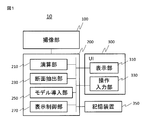
- the medical imaging apparatus 10 is an imaging unit 100 that images a subject and acquires image data, and an image processing unit that performs image processing on image data acquired by the imaging unit 100. 200, a display unit 310 for displaying an image acquired by the imaging unit 100 or an image processed by the image processing unit 200, and a command or data required for the user to input a process of the imaging unit 100 or the image processing unit 200. And an operation input unit 330.
- the display unit 310 and the operation input unit 330 are generally disposed in proximity to each other, and function as a user interface (UI) 300.
- the medical imaging apparatus 10 may further include a storage device 350 that stores image data obtained by the imaging unit 100, data used for processing by the image processing unit 200, processing results, and the like.
- the configuration of the imaging unit 100 differs depending on the modality, and in the case of an MRI apparatus, a magnetic field generating means or the like for collecting magnetic resonance signals from an object placed in a static magnetic field is provided.
- a magnetic field generating means or the like for collecting magnetic resonance signals from an object placed in a static magnetic field.
- an X-ray source for irradiating the subject with X-rays, an X-ray detector for detecting X-rays transmitted through the subject, and an X-ray source and an X-ray detector are rotated around the subject.
- a mechanism to make The ultrasonic diagnostic apparatus includes means for transmitting ultrasonic waves to a subject, receiving ultrasonic waves that are reflection waves from the subject, and generating an ultrasonic image.
- volume data (3D image data) or time-series 2D image data or volume data is obtained.
- volume data 3D image data
- the image processing unit 200 inputs information on a plurality of cross sections included in the 3D volume data, and a cross section extraction unit 230 that extracts a predetermined cross section (referred to as a target cross section) from 3D volume data input from the imaging unit 100. And a model introducing unit 250 for introducing a learning model (a discriminator) that outputs a score indicating the closeness between the cross section and the target cross section to the cross section extraction unit 230.
- a learning model a discriminator
- the target cross section varies depending on the purpose of diagnosis and the purpose of image processing for the cross section, here, the size (width, length, diameter, circumference, etc.) of a predetermined organ or part included in the cross section is measured here
- the cross section is suitable for Further, the image processing unit 200 displays, for example, the cross section extracted by the cross-section extracting unit 230 and the result of the cross-section extracted by the cross-section extracting unit 230 on the image data of the cross section extracted by the cross-section extracting unit 230
- a display control unit 270 for displaying on 310 may be provided.
- the learning model used by the cross-section extraction unit 230 outputs a target cross-sectional image of volume data whose target cross-section is known as a correct image, and outputs a score of similarity between many cross-sectional images included in the 3D volume data and the correct image
- the learning model of the present embodiment is a reduced model (second learning) created by fusing a highly learned learned model (first learned model) and a non-learned model with a smaller number of layers. Model). The reduced model is subjected to the same learning as the learned CNN after fusion.
- the first learned model has a large number of layers, a large number of iterations required for learning, but high learning accuracy.
- the reduced model is a part of each layer of the model learned with such high accuracy, for example, a layer learned particularly with high accuracy including the feature quantity extraction layer, and a layer with a relatively small contribution of learning among unlearned models
- the identification layer on the lower layer side of CNN is combined, and it has a simple configuration in which the number of layers is smaller than that of the first learned model.
- the learning model (reduced model) is created in advance by the medical imaging apparatus 10 or by a computer or the like independent of the medical imaging apparatus 10, and is stored in the storage device 350. Multiple reduced models may be stored depending on the difference in identification task. For example, in the case where there are a plurality of cross sections of the measurement target, for example, each of the head, chest, and legs is created for each measurement target. When there are a plurality of types of target cross sections, they are created according to the type of target cross section. If there are a plurality of reduced models, the model introduction unit 250 calls a necessary model according to the identification task, and passes it to the cross-section extraction unit 230.
- the model introducing unit 250 reads a learning model from the storage unit 251 and reads the learning model from the storage unit.
- a model call unit 253 applied to the The cross-section extraction unit 230 uses the learning model read by the model introduction unit 250 for the cross-section selection unit 231 which selects image data of a plurality of cross sections from the volume data 240 and the image data of the cross section selected by the cross-section selection unit 231.
- a determination unit 235 which analyzes the score which is the output of the cross-section identification unit 233 and determines the target cross-section.
- Some or all of the functions of the image processing unit 200 can be realized as software executed by the CPU.
- a part related to image data generation of the imaging unit and a part of the image processing unit may be realized by hardware such as an application specific integrated circuit (ASIC) or a field programmable gate array (FPGA).
- ASIC application specific integrated circuit
- FPGA field programmable gate array
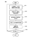
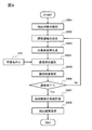
- the operation of the medical imaging apparatus of the present embodiment mainly the flow of processing of the image processing unit 200, will be described with reference to FIG.
- the case where imaging and image display are performed in parallel will be described as an example.
- the type of the target cross section by the user is selected through the operation input unit 330.
- the type of target cross-section is the type of cross-section for measurement or the cross-section for determining the extension direction of a structure, etc., and the type of target cross-section, and the type of measurement target (site or organ or fetus) There is.
- Such an input may be performed when setting an imaging condition, or may be set by default when an imaging condition is set.
- the cross-section selecting unit 231 selects a plurality of cross sections from the 3D image data (S301).
- a plurality of cross sections parallel to the direction are selected and passed to the cross section identification unit 233.
- the Z axis is in the body axis direction
- the XY planes are selected at predetermined intervals. Since the target cross section is not fixed according to the structure (tissue or part) included in the volume data, in this case, cross sections in various directions are selected.
- a so-called "coarse to fine approach” is narrowed from a relatively wide area to a narrow area at each repetition while repeating the selection by the cross-section selection unit 231 and the identification by the cross-section identification unit 233.
- search area the area for selecting a cross section
- the search area is narrowed, the distance between the cross sections to be selected may be narrowed, and the number of angles of the cross section may be further increased.
- the model introducing unit 250 reads the learning model from the storage device 350 according to the type of the target cross section set in advance, and stores the learning model in the model storage unit 251.
- the model calling unit 252 calls the learning model to be applied from the model storage unit 251.
- the cross-section identification unit 233 performs feature extraction and identification of the selected cross-section using the called learning model, and outputs the distribution of the score that is the identification result (S302).
- the distribution of the score is a distribution in which the score indicating the similarity between the target cross section and the cross section to be processed is plotted against the distances from the target cross sections of the plurality of cross sections. The higher the score, the spatial distance from the target cross section Becomes closer distribution.
- the distribution of scores takes a numerical value between 0 and 1, with the score of the section corresponding to the target section as 1.
- the discrimination result judging unit 235 receives the distribution of the score which is the result of the cross-section identifying unit 233, and finally determines the one with the best score, and in the above example, the cross-section having a score of 1 or most nearly 1 as the target cross section S303).
- the display control unit 250 causes the display unit 310 to display the cross section (S304).
- the calculation unit 240 has an automatic measurement function, the structure present in the cross section is measured, and the result is displayed on the display unit 310 via the display control unit 250 (S305). If there are a plurality of identification tasks, or if reprocessing is necessary by user adjustment, the process returns to step S301 (S306) and repeats S301 to S304 (S305).
- the present embodiment it is possible to automatically determine the target cross section in a short time by using a model (classifier) learned in advance to identify the cross section closest to the target cross section.
- the learning model is obtained by fusing a part of the layer of the model which has been highly learned in advance with a part of the layer of the unlearned model having a relatively simple structure and relearning. Because of this, the implementation to the imaging device is easy, and the processing time by the learning model can be significantly reduced. As a result, it is possible to shorten the time from the imaging to the target cross section display or the measurement using the target cross section, and to improve the real time property.
- time-series data is data in which one dimension of 3D is replaced with the dimension of time, and is configured by cross-sectional images of various time phases.
- time-series data is data in which one dimension of 3D is replaced with the dimension of time, and is configured by cross-sectional images of various time phases.
- the target cross section can be searched by performing processing by the image processing unit 200 in parallel while performing imaging continuously.
- the cross-section selecting unit 231 may select only an imaging cross section (a surface in one direction), which enables high-speed processing.
- all imaging cross sections to be imaged at predetermined intervals may be selected.
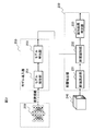
- the ultrasonic diagnostic apparatus 40 includes, as an ultrasonic imaging unit 400, a probe 410, a transmission beam former 420, a D / A converter 430, an A / D converter 440, and a beam former memory 450.
- a reception beam former 460 is provided, and further, an image processing unit 470, a display unit 480, and an operation input unit 490 are provided.
- the probe 410 is composed of a plurality of ultrasonic elements arranged along a predetermined direction. Each ultrasonic element is, for example, a ceramic element produced by ceramic. The probe 410 is disposed in contact with the surface of the test object 101.
- the transmit beamformer 420 transmits ultrasonic waves from at least a portion of the plurality of ultrasonic elements via the D / A converter 430.
- Each ultrasonic wave transmitted from each ultrasonic element constituting the probe 410 is given a delay time to focus at a predetermined depth, and a transmission beam focused at the predetermined depth is generated.
- the D / A converter 430 converts the electrical signal of the transmit pulse from the transmit beamformer 420 into an acoustic signal. Further, the A / D converter 440 converts the acoustic signal received by the probe 410 in the process of propagating inside the inspection object 101 again into an electrical signal to generate a reception signal.
- the beam former memory 450 stores, for each transmission, phasing delay data for each reception focus with respect to the reception signal output from the ultrasonic element via the A / D converter 440.
- Reception beam former 460 receives the reception signal output from the ultrasonic element for each transmission via A / D converter 440, and transmits the phase delay data for each transmission stored in beam former memory 450 and the reception signal received. Generates a phasing signal from.
- the image processing unit 470 generates an ultrasonic image using the phasing signal generated by the reception beam former 460, and automatically generates an optimum image for measurement from the captured 3D volume data or the 2D cross-sectional image group stored in the cine memory. Extract. Therefore, the image processing unit 470 generates a ultrasound image using the phasing signal generated by the reception beam former 460, and a data memory 472 storing image data generated by the data construction unit.
- a Doppler processing unit that processes a Doppler signal may be provided.
- the function of the data configuration unit 471 is the same as that of the conventional ultrasonic imaging apparatus, and generates an ultrasonic image in B mode or M mode.
- the model introducing unit 473 and the cross-section extracting unit 474 implement functions corresponding to the model introducing unit 250 and the cross-section extracting unit 230 of the first embodiment, respectively, and have the same configuration as the functional block diagram shown in FIG. Have. That is, the model introduction unit 473 includes a model storage unit and a model call unit, and the cross-section extraction unit 474 includes a cross-section selection unit (231), a cross-section identification unit (233), and an identification result determination unit (234). In the following description, FIG. 2 is used as appropriate.
- the cross-section selecting unit 231 reads out volume data or a 2D cross-sectional image group of one patient.
- the data read out from the data memory may be moving image data obtained by imaging a two-dimensional cross section, or a dynamically updated image.
- the cross-sectional identification unit 233 identifies the target cross-sectional image group selected by the cross-section selection unit 231 using the learning model introduced by the model introduction unit 473.
- the identification result determination unit 235 analyzes the identification result of the cross-section identification unit 233, and determines whether to end the identification and the next cross-section selection range.
- the automatic measurement unit 475 can be configured by software incorporating a known automatic measurement algorithm, measures the size of a predetermined site, etc. from the extracted one or a plurality of cross sections, and uses a predetermined algorithm The target measurement value is calculated from the values such as size.
- the cross-section adjustment unit 476 receives correction or adjustment by the user via the operation input unit 490 for the cross-section extracted by the cross-section extraction unit 475 displayed on the display unit 480, and changes the cross-sectional position or not.
- the processing instruction is given to the automatic measurement unit 475.
- the display unit 480 displays the ultrasonic image extracted by the image processing unit 470 and the measurement value and the measurement position thereof.
- the operation input unit 490 includes an input device for receiving position adjustment of the cross section extracted by user input, switching of the cross section, and adjustment of the measurement position.
- the image processing unit 470 re-performs a part of the process according to the user input, and updates the display result of the display unit 480.
- This learning model is a highly accurate reduced model that is installed in advance in the device. As shown in FIG. 5, this reduced model is acquired by a model fusion unit that combines and relearns a high accuracy model 510 learned from a learning database 500 and an unlearned model 530 using machine learning. This is a simple model 550 that can be mounted on the device while maintaining the accuracy.
- the function of the model fusion unit can be realized by an image processing apparatus or CPU other than the ultrasonic imaging apparatus 40, but if the ultrasonic imaging apparatus 40 incorporates a CPU, It may be realized by a CPU.
- the learning database 500 stores, in advance, a large number of image data, for example, 3D images of each growth week of the fetus and cross-sectional images used for measurement.
- CNN which is one of Deep Learning (DL), as an example.
- the learned high-accuracy model 510 has a deep layer configuration, and has a plurality of convolutional layers 511 for extracting feature quantities in the previous stage of the layer.
- the folded layers 511 one or more layers adjacent to the input layer in particular are layers contributing to feature amount extraction, and are referred to as a feature amount extraction layer 515.
- a layer close to the full connection layer 513 is a layer that contributes to identification, and is called an identification layer.
- the model 510 has high identification accuracy but a large model size and takes processing time.
- unlearned model 530 has a plurality of convolution layers and full connection layers as model 510, but the layer configuration is simple and small in size, for example, the number of convolution layers is smaller than that of learning model 510, and full connections The number of layer dimensions is small.
- the unlearned model 530 has high identification speed but low accuracy.
- the reduced model 550 performs model fusion of the feature extraction layer 515 which is a part of the layer configuration of the learned model 510 and the identification layer 531 of the unlearned model 530 to construct a new layer configuration, and further learning. It is relearned using the database 500.
- the layer configuration of the models 510, 530, and 550 shown in FIG. 5 is an example for explaining the method of model reduction, and the layer configuration is not limited to that illustrated, and the above-described reduction is described. It includes various layer configurations that can be applied to the approach.
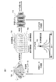
- FIG. 7 is a diagram showing learning model generation for realizing high-speed and high-precision search.
- a learning measurement cross-sectional group 701 and a non-measurement cross-sectional group (a cross section which is not a measurement cross section) 702 are generated from learning volume data 700 and machine learning is performed using these as learning data.
- a learning model 710 is obtained in which features of the measured cross section and the non-measured cross section are automatically extracted.
- the learning model calculates a score (referred to as an identification score) of the measured cross section likelihood with respect to the input cross section (identification cross section), and creates a distribution of scores (score distribution) 705 calculated for each of the plurality of cross sections.
- an identification score referred to as an identification score
- scores score distribution 705 calculated for each of the plurality of cross sections.
- the simplified one-dimensional developed distribution is shown in the figure, it is actually a three-dimensional distribution.
- the identification score of the cross section is higher as it is spatially closer to the measurement cross section position. Therefore, as shown in FIG. 7, the score distribution 705 should be a distribution which is highest at the center and lowers as it goes away from the center, when the measurement cross section position is at the center.
- the score distribution 705 which is the output of the learning model is confirmed, and the learning data is adjusted so that the identification score of the cross section is higher as it is spatially closer to the measurement cross section position.
- the machine learning is repeated by adjusting the weight coefficient of each layer constituting the model.
- the anatomical distance of the living body is used to adjust the spatial distance and acquisition position of the non-measurement cross section and the measurement cross section. By repeating such adjustment, a highly accurate learning model suitable for searching for the measurement cross section is generated from the distribution of the identification score.
- learning models are respectively generated for the plurality of measurement cross sections.
- a score distribution is generated in which the horizontal axis of the score distribution 705 in FIG. 7 is replaced from the space axis to the time axis. Then, taking advantage of the fact that the cross-section of the frame closer to the measurement cross-section on the time axis is similar to the measurement cross-section, the sampling interval of learning data is adjust. As a result, a learning model is generated in the same manner as when volume data is used as learning data.
- the same learning is performed for the above-described reduced model 550 in which the learned model 510 thus learned and the unlearned model 530 are fused.
- the learning rates of the learned model 510 and the unlearned model 530 are adjusted so that learning is performed centering on the identification layer 531. That is, the weight coefficient of the feature quantity extraction layer 515 transferred from the learned model 510 is held, and the learning rate of the identification layer 531 transferred from the unlearned model 530 is increased.
- fetal weight estimation first, as shown in FIG. 8, a volume scan is performed on the fetus 101 to be examined using a mechanical mechanical probe or an electronic 2D probe 410, and volume data is stored in a data memory 472. save.
- the cross section extraction unit 474 calls the volume data 800 acquired from the data memory 472, cuts out a cross section from the cut position 801 in the determined search area, and acquires a target cut surface group 802.
- the cut-out section includes a plane perpendicular to the axis (Z-axis) of volume data, a plane parallel to the Z-axis, a plane obtained by rotating these in the declination direction or the elevation angle direction, and the like.
- the cross section extraction process is started when the user gives an instruction to start extraction.
- the instruction to start measurement may also be an instruction to start extraction.
- the cross-section extraction unit 474 (FIG. 2: the cross-section selection unit 231) controls the data memory 472 to select volume data or continuous imaging of one patient designated in advance by the operator.
- the image group is read out, and the input format, the type of the extraction target, and the type of the cross section to be extracted are identified for the processing target data (step S 901).
- the identification of the input format identifies, for example, 3D data or 2D data.
- the type of the extraction target and the type of the cross-section identify any one of a plurality of parts and cross-sections to be extracted according to the purpose of measurement.
- Step S902 is performed by the “coarse-dense approach” in which a region for extracting a cross section (search region) is narrowed sequentially from a wide region. Therefore, first, the cross-section selecting unit (FIG. 2: 231) determines an initial search area (step S902), and generates a target cross-section group (step 903).
- An example of determination of the search area by the “coarse-dense approach” is shown in FIG. (A) and (c) of FIG. 10 schematically show volume data, which is a rotating body of a fan surface, in a plan view centering on the rotation axis.
- the initial search area 1001 is the whole area of the volume data, and sampling points (black circles) 1002 are set at relatively coarse intervals in the declination direction and the radial direction, and a rotating body passing through the sampling point 1002 Extract the tangential cross section of
- the section identifying unit (FIG. 2: 232) applies the learning model (FIG. 6: reduced learning model 550) called in advance by the model introducing unit 473 to the extracted section group, and It identifies and acquires the score which shows proximity with the object cross section (step S904).
- the processing by the learning model 550 can be performed by parallel processing of the individual cross sections forming the cross section group, and a score distribution in which the scores of the individual cross sections are finally obtained is obtained.
- the learning model used in step S904 is created in advance by the learning process as shown in FIG.
- a model call unit introduces a learning model corresponding to the measurement cross section to be processed.
- the cross-section extraction unit 474 analyzes the distribution of the score, which is the identification result of each cross-section by the learning model (step S 905), and narrows the search area to an area narrower than the initial search area 1001.
- the horizontal axis is the distance from the target cross section
- the vertical axis is the score
- the next search region is narrowed to a region near the peak. If there are multiple peaks, the search area is determined to include multiple peaks.
- the center 1003 of the next search area and the search area 1004 are determined, and from the determined search area 1004, a plurality of sectional groups (cross sections including sampling points indicated by white circles) Extract).
- the learning model is similarly applied to this cross-sectional group to obtain the distribution of the score, and the region from which the cross-sectional group is extracted is narrowed.
- step S 905 it is determined whether the search area is sufficiently narrowed or a cross section suitable for measurement is found based on the analysis result of the score distribution, and it is determined whether the search is ended (step S 906) .
- step S 906 it is determined whether the search is ended.
- a new search area approaching the area which seems to be the measurement cross section is determined based on the analysis of the result (step S902).
- step S902 to step S906 is repeated a plurality of times, and by narrowing down the search area, the optimum measurement cross section can be extracted, whereby the search can be performed at high speed and without omission.
- the direction (angle) of the cross section may be changed not only in the declination direction but also in the elevation angle direction.
- step S906 If it is determined in step S906 that the search has ended, automatic measurement or appropriate manual measurement is performed on the extracted optimal measurement cross section (step S907). Finally, a plurality of extraction results such as the extracted cross section, information on the cross section space, measurement values and measurement positions, and other top candidates are presented (step S 908). The presented extraction result is displayed by the display unit 480, and the process ends.
- the automatic extraction of the cross section is an auxiliary function of diagnosis, and the final diagnosis needs to be determined by the user.
- the cross-section adjustment unit 476 receives a signal from the operation input unit 490
- cross-section adjustment, switching, and measurement review can be realized with a simple operation according to the user's preference.
- a flow of cross section adjustment is shown in FIG. The section adjustment starts the process by receiving a signal from the operation input unit 490 that receives the screen operation of the user after the extraction and display of the measurement section described above are completed.
- the type of input operation is identified according to which of the adjustment of the cross section, the switching, and the review of the measurement is instructed according to the signal of the input (step S 911).
- step S 912 In response to the input, the screen display and the cross-section information held internally are updated in real time (step S 912). It is determined whether the operation input ends (step S 913). When it ends, the final extraction cross section is determined (step S914). Thereafter, automatic measurement is performed on the adjusted cross section (step S 915), and information on the extracted cross section and the measurement result is presented (step S 916) and displayed by the display unit 480 as in the flow shown in FIG. .
- FIG. 1 An example of a screen (UI) displayed on the display unit 480 is shown in FIG.
- This figure illustrates an AC measurement cross section as an example, and on the display screen 1200, a measurement cross section display block 1210, a cross section candidate display block 1220, a position adjustment slider 1230, a block indicating the type of cross section and measurement value, etc. Be done.
- the measurement cross section display block 1210 the measurement cross section 1201 extracted by the cross section extraction unit 474 is displayed. Further, the position 1202 at which the measurement was performed on the measurement cross section 1201 and the measurement value 1204 are displayed.
- a marker 1203 which can be dragged by a user operation is displayed on the measurement position 1202. By the drag operation of the marker 1203, the measurement position 1202 and the measurement value 1204 are updated.
- the spatial positional relationship 1206 of each cross-sectional image in the three-dimensional volume data may be displayed in the cross-sectional candidate display block 1220, and a UI (candidate selection column 1207) for selecting a candidate may be displayed.
- the candidate selection field 1207 is expanded, and the candidate cross sections 1208 and 1209 not extracted are displayed.
- the candidate cross sections are, for example, cross sections at positions close to the extracted cross section, or cross sections with high scores, and although two are shown in the figure, the number of candidate cross sections may be three or more.
- buttons 1208A and 1209A may be provided so that any of the candidate cross sections can be selected.
- the position adjustment slider 1230 is, for example, a UI for adjusting the position so that a cross-sectional image can be extracted from an arbitrary position on volume data.
- the operation input unit 490 transmits a signal to the cross section adjustment unit 476 according to the operation.
- the cross-sectional adjustment unit 476 performs a series of processing such as cross-section update, switching, measurement position update, measurement value update, etc. according to the operation, and displays the processing result on the display unit 480.
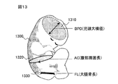
- fetal weight measurement As shown in FIG. 13, BPD (fetal head large lateral diameter) is measured from fetal head cross section 1310 to fetal structure 1300 to be measured, and abdominal cross section 1320 to AC (abdomen Measure the perimeter length, measure the FL (femoral length) from the femoral cross section 1330, estimate the weight of the fetus based on those measured values, compare with the growth curve according to the number of weeks, the fetus is smooth Determine if you are growing into BPD (fetal head large lateral diameter) is measured from fetal head cross section 1310 to fetal structure 1300 to be measured, and abdominal cross section 1320 to AC (abdomen Measure the perimeter length, measure the FL (femoral length) from the femoral cross section 1330, estimate the weight of the fetus based on those measured values, compare with the growth curve according to the number of weeks, the fetus is smooth Determine if you are growing into
- the fetal head cross section As shown in FIG. 14 (a), it is a guideline to use a cross section having structural features such as a skull 1311, a midline 1312, a transparent septa 1313, and a quadriceps tank 1314 as a measurement cross section.
- the measurement target differs depending on the country, for example, in Japan, the BPD (fetal head large lateral diameter) 1315 is measured from the fetal head cross section, and in the West, the OFD (fetal head anteroposterior diameter) 1316, HC It is common to measure 1317).
- the target measurement position may be set in advance of the device or before measurement.
- the measurement can be performed by an automatic measurement unit 475 (FIG. 4) by an automatic measurement technology such as the method described in Patent Document 1, for example.
- an ellipse corresponding to the head is calculated from the features of the tomographic image, and the diameter of the head is calculated.
- a cross section having structural features such as an abdominal wall 1321, an umbilical vein 1322, a gastric vesicle 1323, an abdominal aorta 1324 and a spine 1325 is taken as a measurement cross section.
- AC abbreviations: AC
- APTD abbreviations: APTD
- TTD abdominal lateral diameter
- a cross section having structural features such as the femur 1331, the distal end 1332 which is both ends of the femur, and the proximal end 1333 is recommended by the guidelines.
- FL femoral bone length
- the automatic measurement unit 475 calculates an estimated weight according to, for example, the following equation using each measurement value (BPD, AC, FL) measured in these three cross sections.
- the automatic measurement unit 475 causes the display unit 480 to display the calculated estimated weight.
- the embodiment of the ultrasonic imaging apparatus has been described above by taking the cross section extraction of the AC measurement cross section, the BPD measurement cross section, and the FL measurement cross section necessary for fetal weight measurement as an example, but this embodiment is identified based on the reduced learning model And 4V cross section of the heart (four heart cross section), 3 VV cross section (Three Vessel View), left ventricular outflow tract cross section, right ventricular outflow tract cross section, aortic artery for examining fetal heart function.
- the present invention can also be applied to extraction of arch section and automatic extraction of measurement section of amniotic fluid pocket for measuring fetal amniotic fluid volume.
- the advanced learning model by using the advanced learning model, it is possible to automatically and rapidly perform the cross section extraction highly dependent on the photographer.
- a reduced model in which a learning model having a large layer configuration highly learned and a model having a relatively simple layer configuration are used, mounting on an ultrasonic imaging apparatus can be facilitated and processing can be speeded up. be able to.
- FIG. 15 is a diagram showing acquisition of data and generation of cross-sectional groups from data memory when the extraction target is a continuous 2D cross-section on the time axis.
- a 2D cross section continuously captured in time is accumulated in the data memory 472 while moving the 1D probe with respect to the fetus 101 to be examined.
- the cross section data 1501 read from the data memory 472 is sampled on the time axis to generate a target cross section group 1502. That is, a search area on the time axis is determined, and a frame image on the time axis is selected. Similar to volume data, a coarse-dense approach may be used to determine the search area.
- the target cross-section group is identified using the learning model called in advance by the model introduction unit 473.
- the distribution on the time axis of the identification result is analyzed, and when a cross section suitable for measurement is found, the search is ended and the measurement cross section is determined.
- the cross section called from the data memory may be updated by the imaging operation of the user at that time.
- FIG. 15 shows the case where the 2D cross-sectional data is called from the data memory 472
- the read data may be 3D volume data acquired by one scan or a plurality of 3D volume data continuously scanned in 4D mode.
- the volume is updated after extraction of one cross section from one volume data, and the extraction of the cross section is performed. Finally, one cross section is determined from the candidate cross sections finally extracted from the plurality of volume data.
- the second embodiment and its modification are embodiments in which the present invention is applied to an ultrasonic diagnostic apparatus, but the present invention is applicable to any medical imaging apparatus capable of acquiring volume data or time-series data.
- the image processing unit is a component of the medical imaging apparatus.
- the medical imaging apparatus (the imaging unit 100 in FIG.
- the image processing of the present invention may be performed in an image processing apparatus or an image processing unit separated spatially or temporally from the above.
- Information such as a program, a table, and a file for realizing each function can be placed in a memory, a hard disk, a recording device such as a solid state drive (SSD), or a recording medium such as an IC card, an SD card, or a DVD.
- SSD solid state drive
Landscapes
- Engineering & Computer Science (AREA)
- Health & Medical Sciences (AREA)
- Life Sciences & Earth Sciences (AREA)
- Physics & Mathematics (AREA)
- Theoretical Computer Science (AREA)
- General Health & Medical Sciences (AREA)
- Evolutionary Computation (AREA)
- Molecular Biology (AREA)
- Biophysics (AREA)
- Biomedical Technology (AREA)
- General Physics & Mathematics (AREA)
- Medical Informatics (AREA)
- Artificial Intelligence (AREA)
- Software Systems (AREA)
- Computing Systems (AREA)
- Computer Vision & Pattern Recognition (AREA)
- Data Mining & Analysis (AREA)
- Pathology (AREA)
- Surgery (AREA)
- Veterinary Medicine (AREA)
- Public Health (AREA)
- Radiology & Medical Imaging (AREA)
- Heart & Thoracic Surgery (AREA)
- Animal Behavior & Ethology (AREA)
- Nuclear Medicine, Radiotherapy & Molecular Imaging (AREA)
- General Engineering & Computer Science (AREA)
- Computational Linguistics (AREA)
- Mathematical Physics (AREA)
- Multimedia (AREA)
- Databases & Information Systems (AREA)
- Bioinformatics & Cheminformatics (AREA)
- Bioinformatics & Computational Biology (AREA)
- Evolutionary Biology (AREA)
- Ultra Sonic Daignosis Equipment (AREA)
- Image Analysis (AREA)
Priority Applications (1)
| Application Number | Priority Date | Filing Date | Title |
|---|---|---|---|
| US16/630,581 US20210089812A1 (en) | 2017-07-28 | 2018-06-07 | Medical Imaging Device and Image Processing Method |
Applications Claiming Priority (2)
| Application Number | Priority Date | Filing Date | Title |
|---|---|---|---|
| JP2017146782A JP6824125B2 (ja) | 2017-07-28 | 2017-07-28 | 医用撮像装置及び画像処理方法 |
| JP2017-146782 | 2017-07-28 |
Publications (1)
| Publication Number | Publication Date |
|---|---|
| WO2019021646A1 true WO2019021646A1 (ja) | 2019-01-31 |
Family
ID=65039611
Family Applications (1)
| Application Number | Title | Priority Date | Filing Date |
|---|---|---|---|
| PCT/JP2018/021926 Ceased WO2019021646A1 (ja) | 2017-07-28 | 2018-06-07 | 医用撮像装置及び画像処理方法 |
Country Status (3)
| Country | Link |
|---|---|
| US (1) | US20210089812A1 (https=) |
| JP (1) | JP6824125B2 (https=) |
| WO (1) | WO2019021646A1 (https=) |
Families Citing this family (13)
| Publication number | Priority date | Publication date | Assignee | Title |
|---|---|---|---|---|
| US12014530B2 (en) * | 2018-12-21 | 2024-06-18 | Hitachi High-Tech Corporation | Image recognition device and method |
| EP3913601A4 (en) * | 2019-01-15 | 2022-08-31 | LG Electronics Inc. | LEARNING DEVICE |
| JP7204106B2 (ja) * | 2019-03-03 | 2023-01-16 | 株式会社レキオパワー | 超音波プローブ用ナビゲートシステム、および、そのナビゲート表示装置 |
| KR102318155B1 (ko) * | 2019-06-27 | 2021-10-28 | 고려대학교 산학협력단 | 카메라 촬영 각도 보정 기능을 구비한 양수량 자동 측정 방법 |
| KR102270917B1 (ko) * | 2019-06-27 | 2021-07-01 | 고려대학교 산학협력단 | 인공 지능 모델에 기반한 자궁 양수량 자동 측정 방법 |
| JP7347090B2 (ja) * | 2019-10-02 | 2023-09-20 | 株式会社大林組 | 鉄筋推定システム、鉄筋推定方法及び鉄筋推定プログラム |
| JP7432340B2 (ja) * | 2019-11-07 | 2024-02-16 | 川崎重工業株式会社 | 手術システム及び制御方法 |
| JP7412223B2 (ja) * | 2020-03-02 | 2024-01-12 | キヤノン株式会社 | 画像処理装置、医用画像診断装置、画像処理方法、プログラム、および学習装置 |
| JP7410624B2 (ja) * | 2020-09-14 | 2024-01-10 | キヤノン株式会社 | 超音波診断装置、計測条件設定方法及びプログラム |
| JP2022052345A (ja) * | 2020-09-23 | 2022-04-04 | キヤノンメディカルシステムズ株式会社 | 超音波診断装置、撮像方法、及び撮像プログラム |
| WO2022071264A1 (ja) * | 2020-09-29 | 2022-04-07 | テルモ株式会社 | プログラム、モデル生成方法、情報処理装置及び情報処理方法 |
| WO2023204610A2 (ko) * | 2022-04-19 | 2023-10-26 | 주식회사 온택트헬스 | 심장 초음파에 대한 가이드 방법 및 이를 이용한 심장 초음파에 대한 가이드용 디바이스 |
| GB2636226A (en) * | 2023-12-07 | 2025-06-11 | Mads Nielsen Consultings Aps | A method of, and apparatus for, improved estimation of fetal characteristics |
Citations (1)
| Publication number | Priority date | Publication date | Assignee | Title |
|---|---|---|---|---|
| US20160038122A1 (en) * | 2014-08-05 | 2016-02-11 | Samsung Medison Co., Ltd. | Ultrasound diagnosis apparatus |
Family Cites Families (2)
| Publication number | Priority date | Publication date | Assignee | Title |
|---|---|---|---|---|
| US20160081663A1 (en) * | 2014-09-18 | 2016-03-24 | General Electric Company | Method and system for automated detection and measurement of a target structure |
| US10083372B2 (en) * | 2015-11-03 | 2018-09-25 | Toshiba Medical Systems Corporation | Ultrasound diagnosis apparatus, image processing apparatus and image processing method |
-
2017
- 2017-07-28 JP JP2017146782A patent/JP6824125B2/ja active Active
-
2018
- 2018-06-07 US US16/630,581 patent/US20210089812A1/en not_active Abandoned
- 2018-06-07 WO PCT/JP2018/021926 patent/WO2019021646A1/ja not_active Ceased
Patent Citations (1)
| Publication number | Priority date | Publication date | Assignee | Title |
|---|---|---|---|---|
| US20160038122A1 (en) * | 2014-08-05 | 2016-02-11 | Samsung Medison Co., Ltd. | Ultrasound diagnosis apparatus |
Non-Patent Citations (1)
| Title |
|---|
| TUCKER, G. ET AL.: "Model compression applied to small-footprint keyword spotting", INTERSPEECH, 8 September 2016 (2016-09-08), pages 1878 - 1882, XP055567183 * |
Also Published As
| Publication number | Publication date |
|---|---|
| JP6824125B2 (ja) | 2021-02-03 |
| JP2019024925A (ja) | 2019-02-21 |
| US20210089812A1 (en) | 2021-03-25 |
Similar Documents
| Publication | Publication Date | Title |
|---|---|---|
| JP6824125B2 (ja) | 医用撮像装置及び画像処理方法 | |
| US11450003B2 (en) | Medical imaging apparatus, image processing apparatus, and image processing method | |
| JP6238651B2 (ja) | 超音波診断装置及び画像処理方法 | |
| JP5645811B2 (ja) | 医用画像診断装置、関心領域設定方法、医用画像処理装置、及び関心領域設定プログラム | |
| JP6453857B2 (ja) | 超音波画像の3d取得のためのシステムおよび方法 | |
| US10219782B2 (en) | Position correlated ultrasonic imaging | |
| JP5536678B2 (ja) | 医用画像表示方法、医用画像診断装置、及び医用画像表示装置 | |
| KR101984824B1 (ko) | 초음파를 이용하여 조직의 탄성을 분석하는 방법 및 장치 | |
| JP5558727B2 (ja) | 超音波診断装置および超音波診断装置のデータ処理プログラム | |
| US11672503B2 (en) | Systems and methods for detecting tissue and shear waves within the tissue | |
| CN107072635A (zh) | 用于中间用户反馈的多跳超声心动图采集的质量度量 | |
| JP2014217745A (ja) | 超音波診断装置、およびその制御方法 | |
| US9357981B2 (en) | Ultrasound diagnostic device for extracting organ contour in target ultrasound image based on manually corrected contour image in manual correction target ultrasound image, and method for same | |
| JP6739318B2 (ja) | 超音波診断装置 | |
| JP2014161734A (ja) | 医療画像を整合する方法及びその装置 | |
| JP2017153818A (ja) | 超音波診断装置、超音波診断装置制御プログラム、医用画像処理装置及び医用画像処理プログラム | |
| CN114601494B (zh) | 超声波诊断系统、操作辅助方法以及程序产品 | |
| JP2008289548A (ja) | 超音波診断装置及び診断パラメータ計測装置 | |
| JP5987640B2 (ja) | 超音波を用いた被検体の3次元復元方法および装置 | |
| JP5921610B2 (ja) | 超音波診断装置 | |
| JP2013223625A (ja) | 超音波画像解析装置および超音波画像解析方法 | |
| KR20190060740A (ko) | 초음파를 이용하여 조직의 탄성을 분석하는 방법 및 장치 | |
| CN110934613A (zh) | 超声波诊断装置及超声波诊断方法 |
Legal Events
| Date | Code | Title | Description |
|---|---|---|---|
| 121 | Ep: the epo has been informed by wipo that ep was designated in this application |
Ref document number: 18838067 Country of ref document: EP Kind code of ref document: A1 |
|
| NENP | Non-entry into the national phase |
Ref country code: DE |
|
| 122 | Ep: pct application non-entry in european phase |
Ref document number: 18838067 Country of ref document: EP Kind code of ref document: A1 |