WO2019017429A1 - 燃焼器及びガスタービン - Google Patents
燃焼器及びガスタービン Download PDFInfo
- Publication number
- WO2019017429A1 WO2019017429A1 PCT/JP2018/027085 JP2018027085W WO2019017429A1 WO 2019017429 A1 WO2019017429 A1 WO 2019017429A1 JP 2018027085 W JP2018027085 W JP 2018027085W WO 2019017429 A1 WO2019017429 A1 WO 2019017429A1
- Authority
- WO
- WIPO (PCT)
- Prior art keywords
- fuel
- main
- main burner
- burner
- combustor
- Prior art date
- Legal status (The legal status is an assumption and is not a legal conclusion. Google has not performed a legal analysis and makes no representation as to the accuracy of the status listed.)
- Ceased
Links
Images


Classifications
-
- F—MECHANICAL ENGINEERING; LIGHTING; HEATING; WEAPONS; BLASTING
- F23—COMBUSTION APPARATUS; COMBUSTION PROCESSES
- F23R—GENERATING COMBUSTION PRODUCTS OF HIGH PRESSURE OR HIGH VELOCITY, e.g. GAS-TURBINE COMBUSTION CHAMBERS
- F23R3/00—Continuous combustion chambers using liquid or gaseous fuel
- F23R3/28—Continuous combustion chambers using liquid or gaseous fuel characterised by the fuel supply
- F23R3/286—Continuous combustion chambers using liquid or gaseous fuel characterised by the fuel supply having fuel-air premixing devices
-
- F—MECHANICAL ENGINEERING; LIGHTING; HEATING; WEAPONS; BLASTING
- F02—COMBUSTION ENGINES; HOT-GAS OR COMBUSTION-PRODUCT ENGINE PLANTS
- F02C—GAS-TURBINE PLANTS; AIR INTAKES FOR JET-PROPULSION PLANTS; CONTROLLING FUEL SUPPLY IN AIR-BREATHING JET-PROPULSION PLANTS
- F02C7/00—Features, components parts, details or accessories, not provided for in, or of interest apart form groups F02C1/00 - F02C6/00; Air intakes for jet-propulsion plants
- F02C7/22—Fuel supply systems
- F02C7/228—Dividing fuel between various burners
-
- F—MECHANICAL ENGINEERING; LIGHTING; HEATING; WEAPONS; BLASTING
- F23—COMBUSTION APPARATUS; COMBUSTION PROCESSES
- F23R—GENERATING COMBUSTION PRODUCTS OF HIGH PRESSURE OR HIGH VELOCITY, e.g. GAS-TURBINE COMBUSTION CHAMBERS
- F23R3/00—Continuous combustion chambers using liquid or gaseous fuel
- F23R3/02—Continuous combustion chambers using liquid or gaseous fuel characterised by the air-flow or gas-flow configuration
- F23R3/04—Air inlet arrangements
- F23R3/10—Air inlet arrangements for primary air
- F23R3/12—Air inlet arrangements for primary air inducing a vortex
- F23R3/14—Air inlet arrangements for primary air inducing a vortex by using swirl vanes
-
- F—MECHANICAL ENGINEERING; LIGHTING; HEATING; WEAPONS; BLASTING
- F23—COMBUSTION APPARATUS; COMBUSTION PROCESSES
- F23R—GENERATING COMBUSTION PRODUCTS OF HIGH PRESSURE OR HIGH VELOCITY, e.g. GAS-TURBINE COMBUSTION CHAMBERS
- F23R3/00—Continuous combustion chambers using liquid or gaseous fuel
- F23R3/28—Continuous combustion chambers using liquid or gaseous fuel characterised by the fuel supply
- F23R3/34—Feeding into different combustion zones
- F23R3/343—Pilot flames, i.e. fuel nozzles or injectors using only a very small proportion of the total fuel to insure continuous combustion
-
- F—MECHANICAL ENGINEERING; LIGHTING; HEATING; WEAPONS; BLASTING
- F05—INDEXING SCHEMES RELATING TO ENGINES OR PUMPS IN VARIOUS SUBCLASSES OF CLASSES F01-F04
- F05D—INDEXING SCHEME FOR ASPECTS RELATING TO NON-POSITIVE-DISPLACEMENT MACHINES OR ENGINES, GAS-TURBINES OR JET-PROPULSION PLANTS
- F05D2240/00—Components
- F05D2240/35—Combustors or associated equipment
-
- F—MECHANICAL ENGINEERING; LIGHTING; HEATING; WEAPONS; BLASTING
- F23—COMBUSTION APPARATUS; COMBUSTION PROCESSES
- F23C—METHODS OR APPARATUS FOR COMBUSTION USING FLUID FUEL OR SOLID FUEL SUSPENDED IN A CARRIER GAS OR AIR
- F23C2900/00—Special features of, or arrangements for combustion apparatus using fluid fuels or solid fuels suspended in air; Combustion processes therefor
- F23C2900/07001—Air swirling vanes incorporating fuel injectors
-
- F—MECHANICAL ENGINEERING; LIGHTING; HEATING; WEAPONS; BLASTING
- F23—COMBUSTION APPARATUS; COMBUSTION PROCESSES
- F23R—GENERATING COMBUSTION PRODUCTS OF HIGH PRESSURE OR HIGH VELOCITY, e.g. GAS-TURBINE COMBUSTION CHAMBERS
- F23R2900/00—Special features of, or arrangements for continuous combustion chambers; Combustion processes therefor
- F23R2900/00013—Reducing thermo-acoustic vibrations by active means
-
- F—MECHANICAL ENGINEERING; LIGHTING; HEATING; WEAPONS; BLASTING
- F23—COMBUSTION APPARATUS; COMBUSTION PROCESSES
- F23R—GENERATING COMBUSTION PRODUCTS OF HIGH PRESSURE OR HIGH VELOCITY, e.g. GAS-TURBINE COMBUSTION CHAMBERS
- F23R2900/00—Special features of, or arrangements for continuous combustion chambers; Combustion processes therefor
- F23R2900/03343—Pilot burners operating in premixed mode
Definitions
- the present invention relates to a combustor and a gas turbine.
- Priority is claimed on Japanese Patent Application No. 201-140209, filed Jul. 19, 2017, the content of which is incorporated herein by reference.
- Patent Document 1 proposes a technique for reducing the amount of fuel supplied from a part of main premixing nozzles among a plurality of main premixing nozzles in order to suppress combustion vibration. According to the technology of this patent document 1, it is possible to make the flame of lean premixed air supplied with a small amount of fuel long flame as compared with the flame of premixed air which does not reduce the fuel concentration. ing.
- Patent Document 2 proposes a technique for shifting the ignition position by making the outlet shape of the elliptical extension pipe of a part of the main nozzles different from the outlet shape of the other main nozzles in order to suppress combustion vibration. . According to the technique of this patent document 2, it can prevent that heat generation concentrates on the narrow area
- the combustor described in Patent Document 1 reduces the amount of fuel supplied from some of the main premixing nozzles, so the variation in the fuel concentration distribution of the entire combustor becomes too large, and thus nitrogen oxides (NOx) may increase.
- the main burner described in Patent Document 2 can prevent the premixed air from all the main nozzles from being ignited and burned at the same position, the variation in fuel concentration distribution of the entire combustor becomes too large, too There is a possibility that nitrogen oxides (NOx) will increase.
- Patent Documents 1 and 2 if it is attempted to reduce the variation in fuel concentration distribution in an attempt to suppress nitrogen oxides (NOx), there is a possibility that combustion oscillations may increase.
- it is going to reduce nitrogen oxide (NOx) like patent document 3 there exists a possibility that a combustion vibration may increase.
- This invention is made in view of the said situation, and provides the combustor and gas turbine which can suppress generation
- the combustor is provided with a plurality of circumferentially spaced apart main burners.
- the main burners include a first main burner and a second main burner that respectively generate a mixture.
- the second main burner produces an air-fuel mixture having a more uneven fuel concentration than the first main burner.
- the first main burner and the second main burner are arranged in a non-periodic arrangement pattern all around the circumferential direction.
- the second main burner of the first aspect makes the fuel concentration of the mixture nonuniform than the first main burner in the circumferential direction centering on the main nozzle. You may do so. In this way, the shape of the flame from the second main burner can be slightly changed with respect to the flame from the first main burner in the circumferential direction of the main nozzle.
- the second main burner according to the second aspect is a first fuel discharge hole disposed on the first side in the circumferential direction centering on the main nozzle and discharging the fuel;
- the hole diameter may be larger than one fuel discharge hole.
- the second main burner according to the second aspect is a first fuel discharge hole disposed on the first side in the circumferential direction centering on the main nozzle and discharging the fuel;
- a second fuel discharge hole may be provided, which is disposed on the second side in the circumferential direction about the main nozzle opposite to the first side and discharges the fuel.
- the combustor is a first fuel supply system for supplying the fuel to the first fuel discharge hole, and a second fuel supply for supplying the fuel to the second fuel discharge hole at a pressure different from that of the first fuel supply system. And a system may be further provided.
- the amount of fuel injected from the first fuel discharge hole and the second fuel discharge hole can be made different without changing the diameter of the first fuel discharge hole and the second fuel discharge hole. it can. Therefore, in the second main burner, the fuel concentration around the main nozzle can be easily made uneven.
- a gas turbine includes the combustor according to any one of the first to fourth aspects.
- the increase of nitrogen oxides and the occurrence of combustion oscillation can be suppressed.
- FIG. 6 shows schematic structure of the gas turbine in 1st embodiment of this invention. It is a figure which shows schematic structure of the combustor in 1st embodiment of this invention. It is a figure which shows arrangement
- FIG. 1 is a view showing a schematic configuration of a gas turbine according to a first embodiment of the present invention.
- the gas turbine 1 includes a compressor 2, a combustor 3, and a turbine 4.
- the compressor 2 compresses the air A to generate compressed air.
- the combustor 3 burns the fuel F in the compressed air generated by the compressor 2 to generate a high temperature and high pressure combustion gas.
- the turbine 4 is driven by the combustion gas generated by the combustor 3 and converts the energy of the combustion gas into rotational energy.
- the compressor 2 includes a compressor rotor 6 and a compressor casing 7.
- the turbine 4 also includes a turbine rotor 8 and a turbine casing 9.
- the compressor rotor 6 and the turbine rotor 8 are disposed in series and rotate around a rotation axis Ar.
- the turbine rotor 8 and the compressor rotor 6 are integrally connected, and the compressor rotor 6 and the turbine rotor 8 constitute a gas turbine rotor 10.
- a rotor of a generator GEN is coupled to the gas turbine rotor 10.
- the compressor casing 7 covers and rotatably supports the compressor rotor 6.
- the turbine casing 9 covers and rotatably supports the turbine rotor 8.
- the compressor casing 7 and the turbine casing 9 are connected, and the compressor casing 7 and the turbine casing 9 constitute a gas turbine casing 11.
- the combustor 3 is fixed to the gas turbine casing 11.
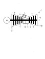
- FIG. 2 is a view showing a schematic configuration of a combustor in the first embodiment of the present invention.
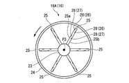
- FIG. 3 is a view showing the arrangement of the main burner in the first embodiment of the present invention.
- the combustor 3 includes a combustion cylinder (or tail cylinder) 13 and a fuel injector 14A.
- the combustion cylinder 13 burns the fuel F therein and sends the combustion gas generated by the combustion of the fuel F to the turbine 4.
- the fuel injector 14 A ejects the fuel F and the compressed air A into the combustion cylinder 13.
- the fuel injector 14 ⁇ / b> A includes a pilot burner 15, a main burner 16, and a burner holding cylinder 17.
- the pilot burner 15 is disposed on the combustor axis Ac to diffuse and burn the fuel.
- the pilot burner 15 includes a pilot nozzle 18, a pilot burner cylinder 19, and a pilot swirler (not shown).
- the pilot nozzle 18 is formed to extend in an axial direction Da centered on the combustor axis Ac.
- the pilot nozzle 18 has, for example, an injection hole 18a for fuel injection at its downstream end.
- the pilot burner cylinder 19 includes a main body portion 21 and a cone portion 22.
- the main body 21 covers the outer periphery of the pilot nozzle 18.
- the cone portion 22 is disposed on the downstream side of the main body portion 21 and is formed so as to gradually increase in diameter toward the downstream side.
- the pilot swirler (not shown) is disposed upstream in the axial direction Da from the position where the injection holes of the pilot nozzle 18 are formed.
- the pilot swirler (not shown) swirls the compressed air (primary air) A flowing from the upstream side about the combustor axis Ac as a turning center.
- the pilot swirler (not shown) extends radially inward from the inner circumferential surface of the main body 21 of the pilot burner barrel 19, for example.
- the pilot swirlers (not shown) are, for example, formed in plural at intervals in the circumferential direction.
- the compressed air A compressed by the compressor 2 flows into the pilot burner cylinder 19 from the upstream side. Further, fuel is injected from the injection holes of the pilot nozzle 18. This fuel is jetted from the pilot burner cylinder 19 toward the combustion cylinder 13 together with the compressed air A to which a swirling component is applied by a pilot swirler (not shown), and is diffused and burned in the combustion cylinder 13.
- a plurality of main burners 16 are provided and arranged to surround the outer periphery of the pilot burner 15 to pre-mix and burn fuel.
- the main burners 16 are spaced circumferentially about the combustor axis Ac, and more specifically, are disposed at equal intervals.
- the main burners 16 in this embodiment include a first main burner 16A and a second main burner 16B.
- the first main burner 16A and the second main burner 16B may be simply referred to as the main burner 16 when it is not necessary to distinguish them.
- symbol is attached
- the first main burner 16A and the second main burner 16B each include a main nozzle 23, a main burner tube 24, and a main swirler 25.
- the main nozzle 23 extends parallel to the combustor axis Ac. These main nozzles 23 are provided with fuel flow paths (not shown) through which fuel flows.
- the main burner cylinder 24 covers the outer periphery of the main nozzle 23.
- the portion disposed inside in the radial direction centering on the combustor axis Ac also serves as a part of the pilot burner cylinder 19.
- the main swirler 25 swirls the compressed air (primary air) A flowing from the upstream side with the main nozzle 23 as a swirl center.
- the main swirlers 25 extend from the outer peripheral surface of the main nozzle 23 toward the inner peripheral surface of the main burner cylinder 24 respectively.
- a plurality of main swirlers 25 are provided at intervals in the circumferential direction centering on the main nozzle 23 in the plurality of provided main burners 16.
- the burner holding barrel 17 holds the pilot burner 15 and the main burner 16 described above. More specifically, the pilot burners 15 and the main burners 16 are held such that the plurality of main burners 16 surround the outer periphery of the pilot burners 15.
- FIG. 4 is a front view showing a schematic configuration of the first main burner in the first embodiment of the present invention.
- FIG. 5 is a front view showing a schematic configuration of a second main burner in the first embodiment of the present invention.
- the main swirlers 25 of the first main burner 16A are provided with fuel discharge parts 26 and 27, respectively.
- the fuel discharge parts 26 and 27 are respectively constituted by a pair of fuel discharge holes 28 formed in the pressure surface 25 a and the negative pressure surface 25 b of the main swirler 25.
- the fuel discharge portion 26 is formed at a position close to the radially outer end of the main swirler 25, and the fuel discharge portion 27 is formed radially inward of the fuel discharge portion 26.
- the fuel discharge holes 28 respectively communicate with the fuel flow path of the main nozzle 23.
- the fuel discharge holes 28 formed in the pressure surface 25 a of the fuel discharge holes 28 are offset radially outward of the fuel discharge holes 28 formed in the negative pressure surface 25 b in each of the fuel discharge portions 26 and 27. doing.
- the fuel discharge holes 28 formed in the first main burner 16A are formed such that the concentration of the fuel F mixed with the compressed air A becomes substantially uniform around the nozzle central axis P3 of the main nozzle 23 .
- all the fuel discharge holes 28 of the fuel discharge portion 26 provided in the first main burner 16A have the same hole diameter.
- all the fuel discharge holes 28 of the fuel discharge portion 27 provided in the first main burner 16A have the same hole diameter.
- the fuel concentration is substantially uniform in the circumferential direction, it is not limited to the case where the diameters of the fuel discharge holes 28 are the same as described above.
- the main swirler 25 of the second main burner 16B is provided with the fuel discharge portions 30, 31 respectively.
- the fuel discharge portions 30, 31 are respectively constituted by a pair of fuel discharge holes 32 formed in the pressure surface 25a and the negative pressure surface 25b of the main swirler 25.
- the fuel discharge portion 30 is formed at a position near the radially outer end of the main swirler 25, and the fuel discharge portion 31 is formed radially inward of the fuel discharge portion 30.
- the fuel discharge holes 32 communicate with the fuel flow path of the main nozzle 23 respectively.
- the fuel discharge holes 32 formed in the pressure surface 25a of each of the fuel discharge portions 30, 31 are offset radially outward of the fuel discharge holes 32 formed in the negative pressure surface 25b. doing.
- the second main burner 16B changes the fuel concentration around the nozzle center axis P3 to supply the premixed mixture to the combustion cylinder 13 more than the first main burner 16A.
- the second main burner 16B in this embodiment changes the fuel concentration around the nozzle center axis P3 to supply the premixed gas to the combustion cylinder.
- the second main burner 16B generates a premixed fuel having an uneven fuel concentration than the first main burner 16A.
- the plurality of fuel discharge holes 32 formed in the second main burner 16B are divided into a first group G1 and a second group G2.
- the discharged fuel reaches a first inner range S1 (see FIG. 3) in the radial direction centering on the combustor axis Ac.
- the fuel discharge holes 32 of the second group G2 reach the outer second range S2 (see FIG. 3) in the radial direction centering on the combustor axis Ac.
- the second main burner 16B in this first embodiment is a fuel discharge portion of the two main swirlers 25 located radially inward (the second side in the circumferential direction) about the combustor axis Ac (see FIG. 3).
- a first group G1 is constituted by the fuel discharge portion 30 of one main swirler 25 adjacent to the main swirler 30 and the two main swirlers 25 in the turning direction.
- the second main burner 16B includes the remaining three main swirlers 25 including two main swirlers 25 located radially outward (first side in the circumferential direction) about the combustor axis Ac (see FIG. 3).
- the second group G2 is formed by the fuel discharge unit 30 of the second embodiment.
- the fuel discharge portion 30 belonging to the first group G1 and the fuel discharge portion 30 belonging to the second group G2 have different opening areas (diameters) of the fuel discharge holes 32 respectively.
- the sizes of the fuel discharge holes 32 provided in the fuel discharge portions 31 of the six main swirlers 25 are all the same.
- the fuel discharge hole 30 of the fuel discharge portion 30 belonging to the first group G1 has an opening area (hole diameter) of the first embodiment.
- the holes 32 are set to "0.9", and the fuel discharge holes 32 of the fuel discharge portion 30 belonging to the second group G2 are set to "1.1".
- the fuel discharge amount of each of the fuel discharge holes 32 disposed radially inward is different from each other.
- the fuel discharge amount of each of the fuel discharge portions 30 of the six main swirlers 25 is divided into two types around the nozzle central axis P3 of the main nozzle 23.
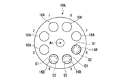
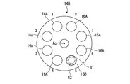
- FIG. 6 is a front view showing the arrangement of the first main burner and the second main burner in the first embodiment of the present invention.
- the fuel injector 14A includes five first main burners 16A continuously arranged in the circumferential direction around the combustor axis Ac and three second mains arranged continuously in the circumferential direction as well. And a burner 16B.
- the fuel injector 14A shown in FIG. 6 shows the case where the eight main burners 16 are provided, but the number of the main burners 16 may be nine or more or seven or less if it is plural. good. Further, the number of first main burners 16A and the number of second main burners 16B are not limited to the above.
- the fuel injector 14A may be provided with both the first main burner 16A and the second main burner 16B.
- the positions of eight main burners 16 arranged in the circumferential direction are indicated by arrangement numbers "1" to "8", respectively.
- the first main burner 16A and the second main burner 16B are arranged in a non-periodic arrangement pattern all around the circumferential direction.
- the pattern of the order in which the first main burners 16A and the second main burners 16B are arranged is the same during one round in the circumferential direction around the combustor axis Ac. It is to be repeated only with the pattern of.
- a periodic case the case where the first main burner 16A and the second main burner 16B are alternately arranged in the circumferential direction, the case where only the first main burner 16A is arranged, or the second main The case where only the burner 16B is disposed can be mentioned.
- the arrangement pattern of the main burners 16 in the fuel injector 14A in this first embodiment is the arrangement of the first main burner 16A and the second main burner 16B while making a round in the circumferential direction around the combustor axis Ac.
- the pattern of the order being ordered is not repeated only with the same pattern.
- the first main burner 16A and the second main burner 16B are arranged in an asymmetrical arrangement pattern in the circumferential direction about the combustor axis Ac.
- the “circumferentially asymmetric arrangement pattern” means that the first main burner 16A and the second main burner 16B are not arranged in the order of so-called rotational symmetry.
- the second main burner 16B of the fuel injector 14A is arranged such that the first group G1 and the second group G2 are divided into an inner side and an outer side in the radial direction centering on the combustor axis Ac. That is, in the fuel injector 14A, the fuel concentration of the premixed gas is uneven in the radial direction centering on the combustor axis Ac at the location where the second main burner 16B is disposed. In other words, in the second main burner 16B, the fuel concentration of the premixed gas is uneven in the circumferential direction around the main nozzle 23. In this first embodiment, the case where the first group G1 is disposed radially inward and the second group G2 is disposed radially outward is illustrated.
- the flame by the first main burner 16A and the flame by the second main burner 16B can be slightly different. Therefore, the fuel concentration distribution can be prevented from becoming uniform in the circumferential direction of the fuel injector 14A in which the main burner 16 is disposed.
- the variation in the amount of fuel discharged by the first main burner 16A and the second main burner 16B can be suppressed, it can be suppressed that the fuel concentration distribution is excessively dispersed in the entire combustor 3. As a result, the increase in nitrogen oxides (NOx) and the occurrence of combustion oscillation can be suppressed.
- NOx nitrogen oxides
- first main burner 16A and the second main burner 16B are not arranged in rotational symmetry, it is possible to suppress uniform fuel concentration distribution in the circumferential direction. Moreover, the shape of the flame by the second main burner 16B can be slightly changed with respect to the flame by the first main burner 16A in the circumferential direction around the nozzle center axis P3.
- the hole diameter (opening area) of the fuel discharge hole 32 (second fuel discharge hole) of the second group G2 is larger than the hole diameter (opening area) of the fuel discharge hole 32 (first fuel discharge hole) of the first group G1. doing. Therefore, the amount of fuel discharged from the fuel discharge holes 32 of the second group G2 can be increased more than the amount of fuel discharged from the fuel discharge holes 32 of the first group G1. As a result, in the second main burner 16B, the fuel concentration around the main nozzle 23 (in other words, around the nozzle center axis P3) can be easily made uneven.
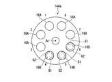
- FIG. 7 is a front view corresponding to FIG. 6 in a modification of the first embodiment of the present invention.
- the arrangement of the first group G1 and the second group G2 in the second main burner 16B is not limited to the arrangement exemplified in the first embodiment.
- the first group G1 and the second group G2 are disposed separately in the circumferential direction about the combustor axis Ac. Also good.
- the first group G1 is disposed radially inward of the combustor axis Ac
- the second group G2 is disposed radially outward of the combustor axis Ac.
- the first group G1 is disposed radially outward with respect to the combustor axis Ac
- the second group G2 is disposed radially inward with respect to the combustor axis Ac.
- the first group A second main burner 16B is disposed radially inward G1 is centered about the combustor axis Ac, and a second main burner G1 is disposed radially outward about the combustor axis Ac Both 16B and 16B may be provided.
- FIG. 8 is a view corresponding to FIG. 6 in the second embodiment of the present invention.
- a fuel injector 14B according to the second embodiment includes a first main burner 16A as a plurality of main burners 16 and a second main burner 16A, similar to the fuel injector 14A of the first embodiment described above. And a burner 16B.
- the first main burner 16A and the second main burner 16B have the same configuration except that the fuel concentration distribution is different.
- first main burners 16A are continuously arranged in the circumferential direction, and only one second main burner 16B is arranged.
- the fuel injector 14B shown in FIG. 8 shows a case where eight main burners 16 are provided as in FIG. 6, but the number of the main burners 16 is nine or more, and seven or less if it is plural. It may be.
- the fuel injector 14B has a non-periodic arrangement pattern over the entire circumference in the circumferential direction.
- the first main burner 16A and the second main burner 16B are disposed.
- the first main burner 16A and the second main burner 16B are arranged in a circumferentially asymmetrical arrangement pattern (arrangement pattern that is not rotationally symmetrical) about the combustor axis Ac. .
- FIG. 8 illustrates the case where the first group G1 is disposed radially outside of the combustor axis Ac and the second group G2 is disposed inside
- the invention is not limited to this arrangement.
- the arrangement of the first group G1 and the second group G2 in FIG. 8 may be interchanged.
- the first group G1 and the second group G2 may be directed in any direction such as a radial direction and a circumferential direction with the combustor axis Ac as a center.
- the fuel concentration distribution by the first main burner 16A and the fuel concentration distribution by the second main burner 16B may be slightly different, as in the first embodiment. it can. Therefore, it can be suppressed that the flame becomes uniform in the circumferential direction of the fuel injector 14A in which the main burner 16 is disposed.
- the amount of fuel discharged by the first main burner 16A and the second main burner 16B becomes uniform, it is possible to suppress excessive variation in fuel concentration distribution in the entire combustor 3. As a result, the increase in nitrogen oxides (NOx) and the occurrence of combustion oscillation can be suppressed.
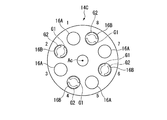
- FIG. 9 is a view corresponding to FIG. 6 in the third embodiment of the present invention.
- a fuel injector 14C according to the third embodiment includes a first main burner 16A as a plurality of main burners 16 and a second main burner 16A, similarly to the fuel injector 14A according to the first embodiment described above. And a burner 16B.
- the first main burner 16A and the second main burner 16B have the same configuration except that the fuel concentration distribution is different.
- the fuel injector 14C in the third embodiment includes four first main burners 16A and four second main burners 16B.
- the fuel injector 14C in the third embodiment shows a case where eight main burners 16 are provided as in the first embodiment, but the number of the main burners 16 is nine or more if it is plural, It may be seven or less.
- the first main burners 16A and the second main burners 16B are alternately arranged in the circumferential direction around the combustor axis Ac.
- the arrangement of the first group G1 and the second group G2 of the second main burner 16B in the third embodiment is not limited to the arrangement shown in FIG. 9 as in the first and second embodiments. .
- the fuel concentration distribution by the first main burner 16A and the fuel concentration distribution by the second main burner 16B may be slightly different, as in the first embodiment. it can. Therefore, the fuel concentration distribution can be prevented from becoming uniform in the circumferential direction of the fuel injector 14A in which the main burner 16 is disposed.
- the amount of fuel discharged by the first main burner 16A and the second main burner 16B becomes uniform, it is possible to suppress excessive variation in fuel concentration distribution in the entire combustor 3. As a result, the increase in nitrogen oxides (NOx) and the occurrence of combustion oscillation can be suppressed.
- the fourth embodiment is different from the first embodiment only in the configuration in which the fuel injection amount of the first group G1 and the fuel injection amount of the second group G2 in the main burner 16B are different. Therefore, while attaching and explaining the same code
- FIG. 10 is a front view corresponding to FIG. 6 in the fourth embodiment of the present invention.
- the main nozzle 23 includes a first fuel supply system F1 and a second fuel supply system F2 which are independent of each other.
- the main burner 16B includes a fuel discharge hole 32 in communication with the first fuel supply system F1 and belonging to the first group G1, and a fuel discharge hole 32 in communication with the second fuel supply system F2 and belonging to the second group G2. .
- the first fuel supply system F1 and the second fuel supply system F2 have different fuel F supply pressures.
- the discharge amount of the fuel F discharged from the discharge hole 32 may be adjustable.
- the first fuel supply system F1 and the second fuel supply may be 0.9: 1.1.
- the fuel discharge hole 32 of the first group G1 and the fuel discharge hole 32 of the second group G2 can be made different. Therefore, in the second main burner 16B, the fuel concentration around the main nozzle 23 can be easily made uneven.
- the arrangement patterns of the first main burner 16A and the second main burner 16B are different from each other, but may be arrangement patterns other than those described above. It is sufficient that both the first main burner 16A and the second main burner 16B be provided, and for example, the arrangement pattern from case 1 to case 22 shown in the following table may be adopted.
- the numbers “1” to “22” described in the leftmost column are cases, and the numbers “1” to “8” described at the top in each column are the embodiments described above.
- the positions “1” to “8” of the main burner 16 in the circumferential direction of The rightmost column is the "number" of the second main burners 16B in one fuel injector.
- case “1” is an arrangement pattern obtained by rotating the arrangement pattern of the second embodiment around the nozzle center axis P3, and substantially the same results were obtained.
- the case “6” is also an arrangement pattern obtained by rotating the arrangement pattern of the first embodiment around the nozzle center axis P3, and substantially the same results were obtained.
- Case “22” is the same arrangement pattern as the third embodiment.
- three patterns of case “1”, case “6” and case “22” will be described as representative examples.
- the present invention is not limited to the configurations of the above-described embodiments, and design changes can be made without departing from the scope of the invention.
- the case where the fuel concentration in the circumferential direction in the first main burner 16A is substantially uniform has been described.
- the variation in the fuel concentration in the circumferential direction in the first main burner 16A may be smaller than that in the second main burner 16B, and is not limited to the case where the fuel concentration is uniform.
- the group having different fuel injection amounts are not limited to two. Three or more groups may be formed.
- the kind of injection quantity is good also as three or more types.
- the configuration has been described in which the second main burner 16B generates the premixed air-fuel mixture having an uneven fuel concentration in the circumferential direction around the nozzle center axis P3.
- the second main burner 16B is configured to be able to suppress the flame dispersion of the entire combustor 3 while making the flame different from the flame of the premixed air generated by the first main burner 16A, the nozzle central axis
- the present invention is not limited to the configuration that makes the fuel concentration uneven in the circumferential direction around P3.
- the fuel discharge holes 28 and 32 are formed in the main swirler 25 , but the fuel discharge holes 28 and 32 are not limited to those formed in the main swirler 25.
- the fuel discharge holes 28 and 32 may be formed on the outer peripheral surface of the main nozzle 23.
- the ratio of the hole diameter of the fuel discharge hole 32 of the first group G1 to the hole diameter of the fuel discharge hole 32 of the second group G2, the fuel discharge hole 32 of the first group G1 and the fuel discharge hole 32 of the second group G2 is not limited to the ratio of each embodiment described above.
- the present invention is applicable to a combustor. According to this combustor, the increase of nitrogen oxides and the occurrence of combustion oscillation can be suppressed.
Landscapes
- Engineering & Computer Science (AREA)
- Chemical & Material Sciences (AREA)
- Combustion & Propulsion (AREA)
- Mechanical Engineering (AREA)
- General Engineering & Computer Science (AREA)
Priority Applications (3)
| Application Number | Priority Date | Filing Date | Title |
|---|---|---|---|
| DE112018003678.2T DE112018003678T5 (de) | 2017-07-19 | 2018-07-19 | Brennkammer und gasturbine |
| US16/629,445 US20200182469A1 (en) | 2017-07-19 | 2018-07-19 | Combustor and gas turbine |
| CN201880047339.3A CN110914595A (zh) | 2017-07-19 | 2018-07-19 | 燃烧器以及燃气轮机 |
Applications Claiming Priority (2)
| Application Number | Priority Date | Filing Date | Title |
|---|---|---|---|
| JP2017140209A JP2019020071A (ja) | 2017-07-19 | 2017-07-19 | 燃焼器及びガスタービン |
| JP2017-140209 | 2017-07-19 |
Publications (1)
| Publication Number | Publication Date |
|---|---|
| WO2019017429A1 true WO2019017429A1 (ja) | 2019-01-24 |
Family
ID=65016245
Family Applications (1)
| Application Number | Title | Priority Date | Filing Date |
|---|---|---|---|
| PCT/JP2018/027085 Ceased WO2019017429A1 (ja) | 2017-07-19 | 2018-07-19 | 燃焼器及びガスタービン |
Country Status (5)
| Country | Link |
|---|---|
| US (1) | US20200182469A1 (https=) |
| JP (2) | JP2019020071A (https=) |
| CN (1) | CN110914595A (https=) |
| DE (1) | DE112018003678T5 (https=) |
| WO (1) | WO2019017429A1 (https=) |
Families Citing this family (2)
| Publication number | Priority date | Publication date | Assignee | Title |
|---|---|---|---|---|
| US20240027069A1 (en) * | 2020-03-31 | 2024-01-25 | Mitsubishi Heavy Industries, Ltd. | Combustor for gas turbine and gas turbine |
| CN117968094A (zh) * | 2024-02-20 | 2024-05-03 | 中国航发四川燃气涡轮研究院 | 阵列多点喷射燃烧室及其一体化喷嘴结构 |
Citations (8)
| Publication number | Priority date | Publication date | Assignee | Title |
|---|---|---|---|---|
| JPH08285240A (ja) * | 1995-04-11 | 1996-11-01 | Mitsubishi Heavy Ind Ltd | 予混合式燃焼器のパイロットバーナ用燃料ノズル |
| JP2001254947A (ja) * | 2000-03-14 | 2001-09-21 | Mitsubishi Heavy Ind Ltd | ガスタービン燃焼器 |
| JP2002257346A (ja) * | 2001-02-22 | 2002-09-11 | Alstom (Switzerland) Ltd | 環状燃焼器を運転するための方法および環状燃焼器 |
| JP2004116988A (ja) * | 2002-09-20 | 2004-04-15 | Siemens Ag | 予混合バーナとガスタービン及び燃料を燃焼させる方法 |
| US20070105061A1 (en) * | 2004-03-31 | 2007-05-10 | Alstom Technology Ltd. | Multiple burner arrangement for operating a combustion chamber, and method for operating the multiple burner arrangement |
| JP2008082330A (ja) * | 2006-09-26 | 2008-04-10 | United Technol Corp <Utc> | 複数の燃焼室部分を有する燃焼器内温度分布の制御方法、燃焼器内の熱音響的不安定性制御方法、および燃焼器内温度分布の制御方法 |
| WO2013128739A1 (ja) * | 2012-02-28 | 2013-09-06 | 三菱重工業株式会社 | 燃焼器及びガスタービン |
| JP2015068538A (ja) * | 2013-09-27 | 2015-04-13 | 三菱日立パワーシステムズ株式会社 | ガスタービン燃焼器およびこれを備えたガスタービン機関 |
Family Cites Families (7)
| Publication number | Priority date | Publication date | Assignee | Title |
|---|---|---|---|---|
| US6176087B1 (en) * | 1997-12-15 | 2001-01-23 | United Technologies Corporation | Bluff body premixing fuel injector and method for premixing fuel and air |
| JPH11294770A (ja) | 1998-04-15 | 1999-10-29 | Mitsubishi Heavy Ind Ltd | 燃焼器 |
| JP2002201966A (ja) * | 2000-12-28 | 2002-07-19 | Toyota Central Res & Dev Lab Inc | ガスタービン用予混合燃焼器およびその燃料供給制御方法 |
| US9719419B2 (en) * | 2011-03-16 | 2017-08-01 | Mitsubishi Heavy Industries, Ltd. | Gas turbine combustor with top hat nozzle arrangements |
| JP6222633B2 (ja) | 2013-11-15 | 2017-11-01 | 三菱日立パワーシステムズ株式会社 | 制御装置、燃焼器、ガスタービン、制御方法及び制御プログラム |
| JP6086860B2 (ja) * | 2013-11-29 | 2017-03-01 | 三菱日立パワーシステムズ株式会社 | ノズル、燃焼器、及びガスタービン |
| JP2017140209A (ja) | 2016-02-10 | 2017-08-17 | 株式会社日立製作所 | 磁気共鳴イメージング装置及び画像処理方法 |
-
2017
- 2017-07-19 JP JP2017140209A patent/JP2019020071A/ja active Pending
-
2018
- 2018-07-19 DE DE112018003678.2T patent/DE112018003678T5/de not_active Withdrawn
- 2018-07-19 WO PCT/JP2018/027085 patent/WO2019017429A1/ja not_active Ceased
- 2018-07-19 US US16/629,445 patent/US20200182469A1/en not_active Abandoned
- 2018-07-19 CN CN201880047339.3A patent/CN110914595A/zh active Pending
-
2021
- 2021-03-30 JP JP2021057819A patent/JP7161567B2/ja active Active
Patent Citations (8)
| Publication number | Priority date | Publication date | Assignee | Title |
|---|---|---|---|---|
| JPH08285240A (ja) * | 1995-04-11 | 1996-11-01 | Mitsubishi Heavy Ind Ltd | 予混合式燃焼器のパイロットバーナ用燃料ノズル |
| JP2001254947A (ja) * | 2000-03-14 | 2001-09-21 | Mitsubishi Heavy Ind Ltd | ガスタービン燃焼器 |
| JP2002257346A (ja) * | 2001-02-22 | 2002-09-11 | Alstom (Switzerland) Ltd | 環状燃焼器を運転するための方法および環状燃焼器 |
| JP2004116988A (ja) * | 2002-09-20 | 2004-04-15 | Siemens Ag | 予混合バーナとガスタービン及び燃料を燃焼させる方法 |
| US20070105061A1 (en) * | 2004-03-31 | 2007-05-10 | Alstom Technology Ltd. | Multiple burner arrangement for operating a combustion chamber, and method for operating the multiple burner arrangement |
| JP2008082330A (ja) * | 2006-09-26 | 2008-04-10 | United Technol Corp <Utc> | 複数の燃焼室部分を有する燃焼器内温度分布の制御方法、燃焼器内の熱音響的不安定性制御方法、および燃焼器内温度分布の制御方法 |
| WO2013128739A1 (ja) * | 2012-02-28 | 2013-09-06 | 三菱重工業株式会社 | 燃焼器及びガスタービン |
| JP2015068538A (ja) * | 2013-09-27 | 2015-04-13 | 三菱日立パワーシステムズ株式会社 | ガスタービン燃焼器およびこれを備えたガスタービン機関 |
Also Published As
| Publication number | Publication date |
|---|---|
| JP7161567B2 (ja) | 2022-10-26 |
| JP2021101152A (ja) | 2021-07-08 |
| JP2019020071A (ja) | 2019-02-07 |
| DE112018003678T5 (de) | 2020-05-14 |
| CN110914595A (zh) | 2020-03-24 |
| US20200182469A1 (en) | 2020-06-11 |
Similar Documents
| Publication | Publication Date | Title |
|---|---|---|
| JP4177812B2 (ja) | タービンエンジンの燃料ノズル | |
| KR101471311B1 (ko) | 가스 터빈 연소기 및 가스 터빈 | |
| EP2660520B1 (en) | Fuel/air premixing system for turbine engine | |
| US11371708B2 (en) | Premixer for low emissions gas turbine combustor | |
| JP5172468B2 (ja) | 燃焼装置および燃焼装置の制御方法 | |
| US9869473B2 (en) | Conical-flat heat shield for gas turbine engine combustor dome | |
| KR102165972B1 (ko) | 버너 어셈블리, 연소기, 및 가스 터빈 | |
| WO2013128572A1 (ja) | 燃焼器及びガスタービン | |
| JP7257358B2 (ja) | ガスタービン燃焼器 | |
| JP7161567B2 (ja) | 燃焼器及びガスタービン | |
| JP6025587B2 (ja) | 燃焼器およびガスタービン | |
| CN118361756A (zh) | 用于氢燃气轮机的燃烧器及其燃烧喷嘴 | |
| CN106716015B (zh) | 燃烧器、燃气轮机 | |
| US9500368B2 (en) | Alternately swirling mains in lean premixed gas turbine combustors | |
| JP6822868B2 (ja) | 燃焼器及びガスタービン | |
| JP5460846B2 (ja) | 燃焼装置および燃焼装置の制御方法 | |
| JP2014126239A (ja) | 燃焼器 | |
| JP2017053523A (ja) | ガスタービン用燃焼器 |
Legal Events
| Date | Code | Title | Description |
|---|---|---|---|
| 121 | Ep: the epo has been informed by wipo that ep was designated in this application |
Ref document number: 18836010 Country of ref document: EP Kind code of ref document: A1 |
|
| 122 | Ep: pct application non-entry in european phase |
Ref document number: 18836010 Country of ref document: EP Kind code of ref document: A1 |