WO2019013327A1 - 移動式衛生設備ユニット - Google Patents
移動式衛生設備ユニット Download PDFInfo
- Publication number
- WO2019013327A1 WO2019013327A1 PCT/JP2018/026505 JP2018026505W WO2019013327A1 WO 2019013327 A1 WO2019013327 A1 WO 2019013327A1 JP 2018026505 W JP2018026505 W JP 2018026505W WO 2019013327 A1 WO2019013327 A1 WO 2019013327A1
- Authority
- WO
- WIPO (PCT)
- Prior art keywords
- floor
- toilet
- toilet unit
- unit
- flush
- Prior art date
- Legal status (The legal status is an assumption and is not a legal conclusion. Google has not performed a legal analysis and makes no representation as to the accuracy of the status listed.)
- Ceased
Links
Images










Classifications
-
- E—FIXED CONSTRUCTIONS
- E03—WATER SUPPLY; SEWERAGE
- E03D—WATER-CLOSETS OR URINALS WITH FLUSHING DEVICES; FLUSHING VALVES THEREFOR
- E03D11/00—Other component parts of water-closets, e.g. noise-reducing means in the flushing system, flushing pipes mounted in the bowl, seals for the bowl outlet, devices preventing overflow of the bowl contents; devices forming a water seal in the bowl after flushing, devices eliminating obstructions in the bowl outlet or preventing backflow of water and excrements from the waterpipe
-
- E—FIXED CONSTRUCTIONS
- E04—BUILDING
- E04H—BUILDINGS OR LIKE STRUCTURES FOR PARTICULAR PURPOSES; SWIMMING OR SPLASH BATHS OR POOLS; MASTS; FENCING; TENTS OR CANOPIES, IN GENERAL
- E04H1/00—Buildings or groups of buildings for dwelling or office purposes; General layout, e.g. modular co-ordination or staggered storeys
- E04H1/12—Small buildings or other erections for limited occupation, erected in the open air or arranged in buildings, e.g. kiosks, waiting shelters for bus stops or for filling stations, roofs for railway platforms, watchmen's huts or dressing cubicles
Definitions
- the present invention relates to mobile sanitary equipment units such as temporary toilets.
- a toilet unit as a temporary toilet in which a toilet bowl or the like of a toilet that constitutes sanitary is arranged in a toilet room is known (see, for example, Patent Document 1).
- the toilet body is disposed below the floor (floor panel) of the toilet room.
- the recessed part which inserts the fork of a forklift is formed in the lower part of the toilet tank main body receiving part which supports a toilet tank. The fork of the forklift is inserted into the recess and the toilet unit is transported by the forklift.
- a flush-type movable toilet without a toilet is also known.
- the level difference from the ground to the floor of the toilet room is high.
- the structure of drainage under the floor requires a drainage space under the floor of the toilet, and as a result of performing foundation work such as attaching a pedestal separately, from the ground to the floor of the toilet room
- the step height is high. Because the height of the steps is high, it is not easy to approach the toilet.
- the configuration of drainage on the floor although the level difference from the ground is reduced, mobility after installation is not considered so much and mobility is not excellent.
- An object of the present invention is to provide a mobile sanitary equipment unit in which the height from the ground to the upper surface of the floor is suppressed and the mobility after installation is excellent.
- the present invention provides a floor (for example, floors 10, 10A, and 10B described below) which forms a bottom of a sanitary facility space (for example, an individual room 2 and a dressing room 2C described later); Sanitary fixtures (for example, toilet bowl 51 and washroom 51C described later) disposed on the upper side of the floor and forming a sanitary fixture, and a fork formed under the floor and having the fork into which the fork of the lift device can be inserted An insertion space (for example, a fork insertion space 1131, which will be described later), and the floor portion forms a ceiling of the fork insertion space; a mobile sanitary facility unit (for example, a toilet unit 1, which is described later; powder room 1C) provide.
- a sanitary facility space for example, an individual room 2 and a dressing room 2C described later
- Sanitary fixtures for example, toilet bowl 51 and washroom 51C described later
- An insertion space for example, a fork insertion space 1131, which will be described later
- the drainage from the said sanitation equipment is discharged by floor drainage.
- the floor preferably has a wheel (for example, a wheel 124 described later) which can be turned 360 ° around the shaft, which enables the mobile sanitary equipment unit to move.
- a water storage pan for example, water storage pan 116 described later
- a pan insertion space formed below the floor for example, floor section 10D described later
- a space for example, a groove 1014D and a through hole 1015D described later
- communicating with the water storage pan from above the floor be formed in the floor portion.
- the said sanitation installation is a toilet.
- the height from the ground to the upper surface of a floor can be restrained, and the mobile sanitary equipment unit which is excellent in the mobility after installation can be provided.
- FIG. 1 It is the plane schematic which shows the position which inserts the water storage pan 116 in the floor part 10F of the flush type movement type toilet unit as a movement type sanitary equipment unit concerning a 7th embodiment of the present invention.
- FIG. 1 An enlarged plan view showing a connecting structure of the front first side panel portion 331H and the rear first side panel portion 332H of a flushable moving toilet unit 1H as a mobile sanitary facility unit according to a ninth embodiment of the present invention It is. It is an enlarged front view which shows the ventilation fan 361I of the flush type movable toilet unit 1I as a movable sanitary equipment unit which concerns on 10th embodiment of this invention. It is an enlarged side view showing ventilation fan 361I of flush type movable toilet unit 1I as a movable sanitary equipment unit according to a tenth embodiment of the present invention.
- FIG. 1 is a perspective view showing a flush-type movable toilet unit 1 as a movable sanitary equipment unit according to a first embodiment of the present invention.
- the mobile sanitary equipment unit according to the present embodiment is, specifically, a flush type mobile toilet unit 1 including a toilet as a sanitary equipment, which is used as a temporary toilet.
- the direction from the back panel 35 to the door panel 31 and the front panel 32 in FIG. 1 (lower right direction in FIG. 1) is defined as the front direction, and the opposite direction is defined as the back direction.
- the direction from the second side panel 34 toward the first side panel 33 in FIG. 1 (lower left direction in FIG. 1) is defined as the left direction, and the opposite direction is defined as the right direction.
- the direction from the floor 10 to the ceiling panel 36 in FIG. 1 (upper direction in FIG. 1) is defined as the upper direction, and the opposite direction is defined as the lower direction.
- the toilet unit 1 has a floor 10, a door panel 31, a front panel 32, a first side panel 33, a second side panel 34, a back panel 35, and a ceiling panel 36.
- the floor 10 and the ceiling panel 36 are each formed in a rectangular shape in plan view. Lower ends of the door panel 31, the front panel 32, the first side panel 33, the second side panel 34, and the back panel 35 are respectively connected to four sides of the floor 10. Further, the four corners of the ceiling panel 36 have the upper end portions of the left and right end portions of the back panel 35 and the front ends of the first side panel 33 and the second side panel 34 in a positional relationship where the floor 10 matches the ceiling panel 36 in plan view. The upper end portions of the portions are connected via the columnar members 301, respectively.
- the floor 10, the door panel 31, the front panel 32, the first side panel 33, the second side panel 34, the back panel 35, and the ceiling panel 36 form a private room 2 as a sanitary facility space.
- the sanitary equipment space is divided into two individual rooms 2 (individual room 2L, individual room 2R) by the central partition panel 37, and in each individual room 2, the toilet bowl 51 as a sanitary equipment is provided on the upper surface of the floor 10 It is done. That is, one flush type movable toilet unit 1 is provided with two toilet bowls 51. A flush water tank 52 is connected to the toilet bowl 51. The flush water tank 52 is accommodated in the diffusive waist wall 352 provided on the back panel 35 located on the rear side of the toilet bowl 51 in each of the individual rooms 2. Each component will be described in detail below.
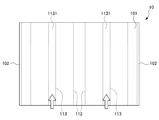
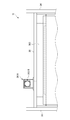
- FIG. 2A is a plan view showing the floor portion 10 of the toilet unit 1 according to the first embodiment of the present invention.
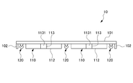
- FIG. 2B is a side view showing the floor portion 10 of the toilet unit 1 according to the first embodiment of the present invention.
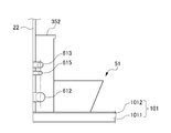
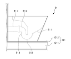
- FIG. 4 is an explanatory view showing a configuration of drainage on the floor in the toilet unit 1 according to the first embodiment of the present invention.
- the floor plate portion 101 has a rectangular floor plate 1011 having a length of about 1.5 m and a width of about 2.0 m in a plan view with a polyvinyl chloride panel 1012 (see FIG. 4 and the like) provided on the upper surface. Because of this size, the flush-type movable toilet unit 1 can be transported by a 4 t (ton) truck and is sized to be transported by a lift device such as a forklift.
- the side plate portion 102 is connected to the short side of the floor plate 1011 in a positional relationship parallel to the vertical direction.
- the lower structure portion 110 has a structure outer portion 112.
- the structure outer portion 112 is formed in a rectangular parallelepiped shape, and the end surface in the longitudinal direction of the structure outer portion 112 is open on the entire surface.
- a central portion in the longitudinal direction of the structural portion exterior 112 has a central square pillar portion 113.
- the central prismatic portion 113 is formed in a quadrangular prism shape, and the end surface in the longitudinal direction of the central prismatic portion 113 is open on the entire surface.
- a fork of a lift device provided with a fork such as a forklift or a hand lift can be inserted into the opening of both end faces of the central square pillar 113, and a space inside the central square pillar 113 can be a fork insertion space 1131 into which the forks can be inserted.
- the floor 10 provided with the central square pillar 113 constitutes the ceiling of the fork insertion space 1131.
- the wheel portion 120 is provided in the vicinity of two long sides of the floor plate 1011 having a rectangular shape in plan view, three three each in total, and in each long side, the center of the long side and both ends of the long side And are arranged.
- FIG. 1 FIG. 2B, the wheel part 120 provided in the front long side of the floor board 1011 has appeared.
- the wheel unit 120 includes a top plate 121, a fork 122, an axle 123, a wheel 124, and a stopper fitting 125.
- the top plate 121 is fixed to the floor plate 1011.
- a through hole is formed at the lower end portion of the fork 122, and an axle 123 passes through the through hole.
- the axle 123 is at an axial center position of the wheel 124 and rotatably supports the wheel 124.
- FIG. 5A is a side view showing a wheel unit 120 of the toilet unit 1 according to the first embodiment of the present invention.
- FIG. 5B is a side view showing the upper portion of the wheel portion 120 of the toilet unit 1 according to the first embodiment of the present invention.
- the upper end portion of the fork 122 is vertically movably supported by a hexagonal nut 128 with respect to a stem 127 fixed to the floor plate 1011. That is, an internal thread is formed on the hexagonal nut 128, and an external thread formed on the circumferential surface of the stem 127 is engaged with the internal thread.
- the fork 122 is rotatable around the stem 127 with respect to the stem 127 and the floor plate 1011, whereby the wheel 124 can pivot 360 ° around the stem 127 as a shaft.
- the wheel unit 120 makes the flush-type movable toilet unit 1 movable.
- the stopper fitting 125 is supported by the fork 122 so as to be rotatable integrally with the locking fitting portion 126 about the axle 123. As the stopper fitting 125 is rotated, the locking fitting portion 126 contacts the wheel 124 and prevents the wheel 124 from rotating. Although the stopper fitting 125 is used here, the stopper fitting 125 may be omitted.
- the drainage from the toilet bowl 51 is not disposed below the floor plate portion 101, and all drainage pipes are drained by drainage on the floor disposed above the floor plate portion 101.
- the toilet bowl 51 is fixed to the floor plate portion 101, and as shown in FIG. 4, the lower end portion of the toilet bowl 511 constituting the toilet bowl 51 is the reservoir water portion 512 of the drainage path of the toilet bowl 51; It is connected to one end of a first drain pipe 611 extending horizontally to the rear side of the toilet bowl 51 via the rising portion 513 and the top portion 514.
- the other end of the first drain pipe 611 is connected to a second drain pipe 612 extending in the left-right direction on the rear side of the back panel 35.
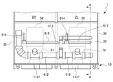
- FIG. 3A is a rear view showing the lower part of the toilet unit 1 according to the first embodiment of the present invention.
- FIG. 3B is an explanatory view for explaining piping of the toilet unit 1 according to the first embodiment of the present invention at a position along the line AA in FIG. 3A.
- a vent pipe 613 is connected to the connection portion of the second drain pipe 612 in the left compartment 2L.
- the vent pipe 613 extends upward from the connection portion and reaches the vicinity of the left end of the left compartment 2L via a bending portion that bends at right angles to the left direction (right direction in FIG. 3A) and is perpendicular to the rear direction. It is broken and in communication with the atmosphere.
- water supply pipes for supplying water to the flush water tank 52 are provided.
- the first water supply pipe 614 extends rearward from the flush water tank 52 of the left compartment 2L and the flush water tank 52 of the right compartment 2R, respectively, and penetrates the pack panel 22 to the back of the pack panel 22. It extends downward and is connected to the second water supply pipe 615.
- the second drainage pipes 612 of the individual compartments 2 are connected and extend in the left-right direction. The left end portion (right end portion in FIG.
- the second water supply pipe 615 is between the ventilation pipe 613 and the second drainage pipe 612 in the vertical direction, and the other end portion of the second drainage pipe 612 in the left and right direction ( At the same position as the right end in FIG. 3A and the left end of the vent pipe 613 (right end in FIG. 3A), it is bent at a right angle, extends backward, and is connected to a flush water supply source such as water service.
- the portion of the second water supply pipe 615 extending in the left-right direction is disposed at the same position as the second drain pipe 612 and the ventilation pipe 613 in the front-rear direction as shown in FIG. 3B.
- the movement of the flush-type movable toilet unit 1 having the above configuration is performed using a forklift or wheels 124. Specifically, first, the two forks of the forklift are inserted into the fork insertion space 1131 from the opening at the front end or the opening at the rear end of the central square pillar 113 of the lower structure 110. . Then, the flush-type movable toilet unit 1 is lifted by a fork and transported to a place to be newly disposed. Then, before lowering the flush-type movable toilet unit 1 lifted by the fork or after lowering the toilet unit 1, the lowermost portion of the wheel 124 is the side plate portion 102 by rotating the hexagonal nut 128 with a spanner or the like. The wheel 124 is protruded downward so as to be located below the lower end of the lower structure and the lower end of the lower structure 110.
- the flush type movable toilet unit 1 lifted by the fork is lowered to land the wheels 124.
- the fork is pulled out from the central square pillar portion 113 of the lower structure portion 110, and the wheel 124 is rotated to move slightly, thereby moving the flush type movable toilet unit 1 to the position where it is finally disposed.
- the hexagonal nut 128 is rotated by a spanner or the like so that the lowermost portion of the wheel 124 does not protrude below the lower end portion of the side plate portion 102 and the lower end portion of the lower structure portion 110.
- the movement of the flush-type movable toilet unit 1 is completed.
- the flush-type movable toilet unit 1 in this embodiment includes the floor 10 forming the bottom of the individual room 2 as the sanitary installation space, and the sanitary installation disposed above the floor 10 to constitute the sanitary installation. It has a toilet bowl 51 as an appliance, and a fork insertion space 1131 formed below the floor 10 and into which a fork such as a forklift or a hand lift can be inserted.
- the floor portion 10 constitutes a ceiling of the fork insertion space 1131.
- the floor portion 10 forms a ceiling of the fork insertion space 1131. It becomes possible to suppress the level difference from the ground to the floor plate portion 101 of the floor portion 10 to a low level.
- the floor portion 10 can be configured as a simple and uncomplicated structure, and the number of parts constituting the flush-type movable toilet unit 1 can be reduced.
- the floor portion 10 constitutes the ceiling of the fork insertion space 1131, when moving the flush-type movable toilet unit 1 with a forklift or the like, the flush-type movable toilet unit 1 is placed and the fork of the forklift is mounted. There is no need to separately arrange the frame to be inserted, and it is possible to reduce the time and effort of movement of the flush-type movable toilet unit 1. And it can be made to move easily by the lift apparatus provided with forks, such as a forklift and a hand lift.
- the floor portion 10 has a wheel 124 capable of turning 360 ° around a stem 127 as a shaft portion, which enables the flush type movable toilet unit 1 to move.
- a wheel 124 capable of turning 360 ° around a stem 127 as a shaft portion, which enables the flush type movable toilet unit 1 to move.
- forks such as a forklift and a hand lift
- the wheel 124 is protruded or retracted downward from the lower structure portion 110 as necessary. It is possible. For this reason, it is possible to use the wheel 124 only when moving the flush-type movable toilet unit 1.
- two private rooms 2 are provided as sanitary space.
- this configuration it is possible to reduce the number of construction steps of the flush-type movable toilet unit 1 as compared to the case of a toilet unit having only one toilet.
- the construction man-hours are greatly reduced compared to the case where the toilet units having only one toilet are arranged one by one.
- the container type toilet unit having 5 to 6 toilets has too many toilets per one toilet unit, which is large in size and inflexible, but if it has a configuration with two toilets, it is flushable
- the combination of the movable toilet unit 1 makes it easy to create various layouts and spaces.
- the sanitary equipment is a toilet provided with the toilet bowl 51.
- the toilet can be easily transported and installed not only at the event site and the like but also at a distribution warehouse, a factory, and the like.
- the flush-type movable toilet unit 1 as a mobile sanitary equipment unit can be used as a temporary toilet or can be used as a permanent toilet.
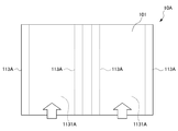
- FIG. 6A is a plan view showing the floor portion 10A of the toilet unit according to the second embodiment of the present invention.
- FIG. 6B is a side view showing the floor portion 10A of the toilet unit according to the second embodiment of the present invention.
- the configuration of the floor portion 10A is different from the configuration of the floor portion 10 in the first embodiment.
- the structure similar to 1st Embodiment it illustrates using the same code
- the floor portion 10A includes a floor plate portion 101, a lower structure portion 110A, and a wheel portion 120.
- the lower structural portion 110A is configured of a prismatic portion 113A having the same configuration as the central prismatic portion 113 in the first embodiment.
- One square pillar 113A is provided at each end of the floor plate 101 in the left-right direction, and a pair of prisms 113A is provided at the center in the left-right direction of the floor plate 101 at predetermined intervals in the left-right direction.
- the fork of the forklift is the fork insertion space 1131A between the square pillar 113A at the left end and the square pillar 113A at the center, the square pillar 113A at the right end, and the square pillar at the center And the fork insertion space 1131A between the portions 113A.
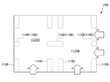
- FIG. 7A is a plan view showing the floor portion 10B of the toilet unit according to the third embodiment of the present invention.
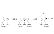
- FIG. 7B is a side view showing the floor portion 10B of the toilet unit according to the third embodiment of the present invention.
- the configuration of the floor portion 10B is different from the configuration of the floor portion 10 in the second embodiment.
- 2nd Embodiment it illustrates using the same code
- the floor portion 10B has a floor plate portion 101, a lower structure portion 110B, and a wheel portion 120.
- the lower structure portion 110B has a prismatic portion 113B shaped as if the central portion of the prismatic portion 113A in the second embodiment in the front-rear direction is removed. Further, at the removed position, a portion corresponding to the central portion of the left compartment 2L and the central portion of the right compartment 2 of the square pillar 113B extending in the left-right direction from the left end to the right end of the floor 10B is removed A partial prismatic portion 114B is provided which constitutes the lower structure portion 110B in the shape as described above.
- the fork of the forklift is a fork insertion space 1131B between the square pillar 113B at the left end and the square pillar 113B at the center, the square pillar 113B at the right end and the square pillar at the center And the fork insertion space 1131B between the portions 113B.
- the fork of the forklift inserts forks on both sides of the partial prism 114B (between the partial prism 114B and the prism 113B) so as to sandwich the partial prism 114B from left or right. It is inserted into the space 1131B.
- FIG. 8 is a perspective view showing a powder room 1C as a mobile sanitation unit according to a fourth embodiment of the present invention.
- the mobile sanitation unit according to the fourth embodiment is a mobile powder room 1C used as a temporary powder room.
- the mobile powder room 1C has a floor 10, a front panel 32, a first side panel 33, a second side panel 34, a back panel 35, and a ceiling panel 36.
- the front panel 32 is disposed at the left and right ends of the front of the movable powder room 1C, and a rectangular opening is formed at the center of the front of the movable powder room 1C as an entrance and exit.
- the floor 10, the front panel 32, the first side panel 33, the second side panel 34, the back panel 35, and the ceiling panel 36 form a restroom 2C as a sanitary space.
- a fusible waist wall 352 is provided from the left end to the right end in the left-right direction of the pack panel 22.
- a wash basin 51C is provided at the center of the flexible waist wall 352 in the left-right direction.
- a mirror 52C formed in a rectangular shape is provided above the wash basin 51C. The drainage from the wash basin 51C is discharged to the sewer by floor drainage as in the first embodiment.
- a vanity shelf 353 is provided on each of the first side panel 33 and the second side panel 34.
- the cosmetic shelf 353 is a front surface portion of the first side panel 33 from the flexible waist wall 352 along the inner surface of the first side panel 33 and the second side panel 34 in a positional relationship flush with the upper surface of the flexible waist wall 352. It extends to the front end of the second side panel 34.
- mirrors 52C formed in a rectangular shape are provided side by side in a pair of front and rear directions.
- mobile powder room 1C of the above-mentioned composition it can move easily with a lift device provided with forks, such as a forklift and a hand lift. For this reason, it is possible to provide the powder room 1C having a comfortable sanitary equipment space in consideration of women even in outdoor events and the like.
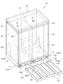
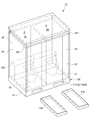
- FIG. 9 is a perspective view showing the water storage pan 116 removed from the flush-type movable toilet unit 1D.
- FIG. 10 is a schematic plan view showing the positional relationship between the groove 1014D on the upper surface of the floor 10D of the toilet unit 1D and the water storage pan 116.
- the configuration of the floor portion 10D is different from the configuration of the floor portion 10 in the first embodiment.
- the structure similar to 1st Embodiment it illustrates using the same code
- a portion which is the lower side of the floor 10D and which is the structure outside 112 (see FIG. 2A, FIG. 2B, etc.) except the central prismatic portion 113 is formed in a quadrangular column shape.
- the end face is open at the entire surface.
- This portion constitutes a pan insertion space 1121D into which the water storage pan 116 can be inserted as shown in FIG.
- the water storage pan 116 inserted into the pan insertion space 1121D is placed on the bottom wall 1122D of the structure exterior 112 (see FIG. 2A, FIG. 2B, etc.) constituting the pan insertion space 1121D in the pan insertion space 1121D. It is stored in the state.
- the bottom surface of the water storage pan 116 is gradually inclined downward toward the lower right of FIG. 9 which is the front direction, and as shown in FIG. 9, the front end of the bottom surface of the water storage pan 116 is It is at the lowest position. Therefore, the liquid stored in the water storage pan 116 is configured to gradually get deeper as it travels forward.
- the entire top surface of the water storage pan 116 inserted into the pan insertion space 1121D is open, and has a rectangular parallelepiped shape having a volume of about 20 liters (liter).
- a flow path communicating with the water storage pan 116 from above the floor is formed.
- the flow path has a groove 1014D formed on the upper surface of the floor 10D and a through hole 1015D vertically penetrating the floor plate 1011D.
- the grooves 1014D extend on the left side, the front side, and the right side of the toilet bowl 51 so as to surround the toilet bowl 51 in each individual chamber 2 (see FIG. 9) as shown in FIG. It is formed.
- the front portion of the toilet bowl 51 is lower than the other portions, and the liquid flowing into the groove 1014D is configured to be collected in the front portion of the toilet bowl 51.
- a through hole 1015D is provided in a portion on the front side of the toilet bowl 51 in the groove 1014D. As shown in FIG. 10, the through holes 1015D are located in the vicinity of the left end and the vicinity of the right end of the water storage pan 116 in the vertical direction. The opening at the upper end portion of the through hole 1015D opens at the bottom of the groove 1014D, and the opening at the lower end portion of the through hole 1015D opens toward the water storage pan 116 in the pan insertion space 1121D. Accordingly, the liquid collected in the front portion of the toilet bowl 51 in the groove 1014D is configured to be collected in the water reservoir pan 116 through the through hole 1015D.
- a fork of a lift device including a fork such as a forklift or a hand lift is inserted into the fork insertion space 1131 and is transported.
- the water storage pan 116 and a pan insertion space 1121D formed below the floor 10D and into which the water storage pan 116 can be inserted are provided. Therefore, a waterproof pan can be installed adjacent to the fork insertion space 1131 which is a dead space at the time of actual use.
- a groove 1014D and a through hole 1015D are formed as a flow path communicating with the water storage pan 116 from above the floor. For this reason, it is possible to lead the overflowed water to the water storage pan 116 via the groove 1014D and the through hole 1015D at the time of emergency (toilet clogging).
- the flush-type movable toilet unit 1D is disposed indoors, it is possible to suppress the overflowing water from flowing into the interior of the building.
- FIG. 11 is a perspective view showing the water storage pan 116 removed from the toilet unit 1E.
- the configuration of the floor portion 10E of the flush-type movable toilet unit 1E is different from the configuration of the floor portion 10 in the first embodiment.
- the structure similar to 1st Embodiment it illustrates using the same code
- the fork insertion space 1131E and the pan insertion space 1121E are shared. That is, when moving the toilet unit 1E, two forks such as a forklift are inserted into the fork insertion space 1131E from the opening at the front end or the opening at the rear end. Then, the flush-type movable toilet unit 1 is lifted by a fork and transported to a place to be newly disposed.
- the space used as the fork insertion space 1131E is used as the pan insertion space 1121E, and the water storage pan 116 is inserted into the pan insertion space 1121E. On the toilet unit 1E.
- the water storage pan 116 can be easily attached and removed.
- the water storage pan 116 is removed and can be used as a fork insertion space 1131E.
- FIG. 12 is a schematic plan view showing the position where the water storage pan 116 is inserted in the floor portion 10F of the toilet unit.
- the configuration of the floor portion 10F of the flush-type movable toilet unit is different from the configuration of the floor portion 10E in the sixth embodiment.
- the same composition as a 6th embodiment it illustrates using the same numerals, and omits explanation.
- the fork insertion spaces 1131E and 1131F and the pan insertion spaces 1121E and 1121F are shared, and in addition to the fork insertion space 1131E and the pan insertion space 1121E in the sixth embodiment.
- a fork insertion space 1131F and a pan insertion space 1121F into which two forks of a forklift can be inserted in the left-right direction are formed.
- the fork insertion spaces 1131E and 1131F and the pan insertion spaces 1121E and 1121F are formed in the front-rear direction and the left-right direction of the toilet unit 1F. Accordingly, it is possible to move the toilet unit 1F by selecting one of the front and rear direction and the left and right direction and inserting two forks such as a forklift. Moreover, it is also possible to insert two forks, such as a forklift, from the rear side (the upper side in FIG. 12) or from the left side as well as the direction shown by the arrow in FIG.
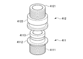
- FIG. 13 is a perspective view showing a female connection joint 412 of a water supply pipe on the building side connected to the toilet unit and a male connection joint 411 of a water supply pipe of the toilet unit.
- FIG. 14 is a perspective view showing a female connection joint 422 of the drainage pipe on the building side connected to the toilet unit and a male connection joint 421 of the drainage pipe of the toilet unit.
- the water supply pipe and drainage pipe of the flush type movable toilet unit, and the water supply pipe and drainage pipe in the event site where the toilet unit is installed as a temporary toilet, in the distribution warehouse or in the factory differs from the toilet unit in the first embodiment in that a connection joint without tools is used for easy connection and disconnection.
- the description of the same configuration as that of the first embodiment will be omitted.
- the male connection joint 411 provided at the end of the water supply pipe of the toilet unit has a hose connection portion 4111, a central flange portion 4112, and a connected portion 4113.
- a male screw portion is formed in the hose connection portion 4111, and the hose connection portion 4111 is inserted and connected to the end portion of the elastically deformable flexible hose (not shown) up to the central flange portion 4112.
- the flexible hose (not shown) has a length of about 50 cm to 1 m from the male connection joint 411, and the other end of the flexible hose connected to the male connection joint 411 is a joint (not shown). Is connected to the water supply pipe (not shown) of the toilet unit.
- the fixed annular portion 4122 of the female connection joint 412 provided at the end of the water supply pipe on the building side is connected to the connected portion 4113 in a covering manner.
- the female connection joint 412 provided at the end of the water supply pipe on the building side has a hose connection portion 4121 and a fixing annular portion 4122.
- An external thread portion is formed in the hose connection portion 4121, and the hose connection portion 4121 is inserted into and connected to the end portion of the water supply pipe on the building side up to the fixing annular portion 4122.
- the fixing annular portion 4122 is connected to the connected portion 4113 of the male connection joint 411 provided at the end of the water supply pipe on the toilet unit side so as to cover it.
- the female connection joint 412 is fixed relative to the male connection joint 411 by the fixing annular portion 4122 being pulled toward the male connection joint 411 and being covered and engaged with the connected portion 4113. And they are connected together in a liquid tight manner.
- the male connection joint 421 provided at the end of the drainage pipe of the toilet unit has a hose connection portion 4211, a central flange portion 4212 and a connected portion 4213.
- the hose connection portion 4211 is inserted into and connected to an end portion of a flexible hose (not shown) which can be elastically deformed up to the central flange portion 4212.
- the flexible hose (not shown) has a length of about 50 cm to 1 m from the male connection joint 421, and the other end of the flexible hose connected to the male connection joint 421 is not shown. Is connected to the drain pipe of the toilet unit.
- the fixed annular portion 4222 of the female connection joint 422 provided at the end of the drainage pipe on the building side is connected to the connected portion 4213 in a covering manner.
- the female connection joint 422 provided at the end of the drainage pipe on the building side has a hose connection portion 4221 and a fixing annular portion 4222.
- a male screw portion is formed in the hose connection portion 4221, and the hose connection portion 4221 is inserted into and connected to the end portion of the drainage pipe on the building side up to the fixing annular portion 4222.
- the fixing annular portion 4222 is connected to the connected portion 4213 of the male connection joint 421 provided at the end of the drainage pipe on the toilet unit side so as to cover it.
- the female connection joint 42 is fixed relative to the male connection joint 421 by the fixing annular portion 4222 being pulled toward the male connection joint 421 and covered and engaged with the connected portion 4213. And they are connected together in a liquid tight manner.
- the toilet unit is provided in the event hall, the distribution warehouse or the factory indoors, and the water supply pipe of the toilet unit and the drainage pipe are respectively toolless and water supply pipe on the building side, It can be easily desorbed into the drain pipe. Further, by using the flexible hose, it is possible to easily adjust the position of the water supply pipe and the drainage pipe on the toilet unit side and the piping of the water supply pipe and the drainage pipe on the building side. As a result, the mobility of the flush-type movable toilet unit can be enhanced, and the toilet unit can be easily installed, removed, added, etc., and it has been considered as a flexible indoor space, not previously considered. The use of flush type mobile toilet unit can be realized.
- FIG. 15 is a front view showing piping of a water supply pipe and a drainage pipe in the toilet unit 1H.
- FIG. 16 is a plan view showing the toilet unit 1H.
- FIG. 17 is an enlarged plan view showing a connection structure between the right back panel 352H and the rear second side panel 342H of the toilet unit 1H.
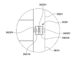
- FIG. 18 is an enlarged plan view showing a connecting structure of the front second side panel portion 341H and the rear second side panel portion 342H of the toilet unit 1H.
- the toilet unit 1 in the first embodiment is different in that a hand-washer 54H is provided in the separate room 2H of the flush-type movable toilet unit 1H.
- a hand-washer 54H is provided in the separate room 2H of the flush-type movable toilet unit 1H.
- explanation is omitted using the same numerals.
- a toilet bowl 51 and a hand-washer 54H are provided in the individual room 2H of the toilet unit 1H, and a flush water tank 52H for supplying flush water to the toilet bowl 51 is provided between them. Further, a motor unit 55H is provided at the rear of the toilet bowl 51.
- the upper end portion of the water supply pipe 413H protrudes above the ceiling panel 36, and the water supply pipe 413H extends downward and bends horizontally at the rear of the toilet bowl 51 and extends horizontally, and below the flush water tank 52H. It extends to the position below the handwasher 54H via the position of.
- a tank water supply pipe (not shown) supplying water to the washing water tank 52H and a hand wash water supply pipe (not shown) supplying water to the discharge port of the handwasher 54H. It is done.
- the drainage pipe 4231H of the handwasher 54H extends downward from the handwasher 54H, bends horizontally in the drainage trap, further extends obliquely downward, and further extends horizontally and is connected to the motor unit 55H.
- the drainage pipe 4232H of the toilet bowl 51 extends rearward from the rear end of the toilet bowl 51 and is connected to the motor unit 55H.
- the drainage pipe 423H extends horizontally above the motor unit 55H, bends upward and extends upward, and the upper end of the drainage pipe 423H is positioned so as to protrude above the ceiling panel 36.
- the first side panel 33H has a front side first side panel portion 331H and a rear side first side panel portion 332H, which are connected by a connecting member 333H.
- the second side panel 34H has a front second side panel portion 341H and a rear second side panel portion 342H, which are connected by a connecting member 343H.
- the back panel 35H also includes a left back panel 351H and a right back panel 352H, which are connected by a connecting member 353H.
- the connecting member 343H is constituted by a pair of opposing members 3431H, and the outer surface 3432H of the opposing member 3431H has a concave shape.
- the thread is screwed onto the pair of opposing members 3431H so that the tip of the pair of opposing members 3431H can be screwed.
- the part is brought into contact with the other of the pair of opposing members 3431H and rotated to widen the space between the pair of opposing members 3431H.
- the connecting member 343H is engaged with the end of the front second side panel 341H and the end of the rear second side panel 342H to form the front second side panel 341H and the rear second. It is comprised so that the side panel part 342H may be connected.
- the first side panel 33H also has a similar configuration (see FIG. 16), and the back panel 35H also has a similar configuration (see FIG. 16).
- the right side back panel portion 352H and the rear side second side panel portion 342H of the back panel 35H see FIG. 17
- a connecting member 343H and a connecting member 333H are respectively provided, and they are connected to each other.
- the motor unit 55H can drain water from the upper end portion of the drain pipe 423H which is disposed above the upper ceiling panel 36 of the toilet unit 1H. Therefore, it is not necessary to dispose the drain pipe 423H on the rear side of the toilet unit 1H. For this reason, it is possible to arrange the back panel 35H of the toilet unit 1H extremely close to the event site where the toilet unit 1H is installed, the inner wall of the distribution warehouse or the building of the factory.
- FIG. 19 is an enlarged front view showing the ventilation fan 361I of the toilet unit 1I.
- FIG. 20 is an enlarged side view showing the ventilation fan 361I of the flush-type mobile toilet unit 1I as the mobile sanitary facility unit according to the tenth embodiment of the present invention.
- the tenth embodiment differs from the toilet unit 1 in the first embodiment in that a deodorizing filter 3622I is attached to the exhaust port 3611I of the ventilation fan 361I of the flush-type movable toilet unit 1I.
- a deodorizing filter 3622I is attached to the exhaust port 3611I of the ventilation fan 361I of the flush-type movable toilet unit 1I.
- explanation is omitted using the same numerals.
- a ventilating fan 361I is provided on the upper surface of the upper ceiling panel 36, and as shown in FIG. 20, an exhaust port 3611I of the ventilating fan 361I is directed in the horizontal direction.
- a filter case 3621I is fixed to the exhaust port 3611I of the ventilation fan 361I. Therefore, the lower chamber space 365 of the upper ceiling panel 36 communicates with the outside of the toilet unit 1I through the ventilation fan 361I and the deodorizing filter 3622I of the filter case 3621I.
- a lid 3623I that can be opened and closed is provided on the top surface of the filter case 3621I, and the deodorizing filter can be replaced by opening the lid 3623I.
- the flush-type movable toilet unit 1I configured as described above, odorous substances generated due to excrement in the toilet unit 1I can be removed by the deodorizing filter 3622I having no problem of pressure loss. For this reason, it becomes unnecessary to connect the toilet unit 1I arrange
- the floor portion, the sanitary equipment, the fork insertion space, the movable sanitary equipment unit, the wheel portion, and the like are the floor portion 10, the toilet bowl 51 or the wash basin 51C in this embodiment, the internal space of the central square pillar portion 113, the flush type movement It is not limited to the toilet unit 1 or the mobile powder room 1C, the wheel unit 120 and the like.
- the floor portion 10 is not a concept including only the floor plate 1011 but is configured by the floor plate 1011, the polyvinyl chloride panel 1012, and the like, but is not limited to this configuration.
- the mobile sanitary equipment unit was comprised by the toilet unit 1 with which the toilet bowl 51 was fixed to the floor part, the toilet bowl may be fixed to the back panel 35 or the waist wall 352.
- one wash basin 51C of the movable powder room 1C is provided, two wash basins 51C may be provided in one movable powder room 1C.
- a hand-washer may be provided in the private room 2 of the flush-type movable toilet unit 1, a hand-washer may be provided.
- the ceiling panel 36 may not be provided.
- 1015D was formed, a channel is not limited to these composition. Further, the number of through holes is not limited to the number of through holes 1015D.
- the configuration of the water storage pan is not limited to the configuration of the water storage pan 116.
- a handle may be provided on the front end face of the water storage pan.
- a through hole may be formed in the lower portion of the front surface of the water storage pan 116, and the through hole may be closed by a plug not shown. That is, the liquid accumulated in the water storage pan 116 may be removed from the water storage pan 116 by opening the stopper and opening the through hole.
Landscapes
- Engineering & Computer Science (AREA)
- Architecture (AREA)
- Civil Engineering (AREA)
- Structural Engineering (AREA)
- Health & Medical Sciences (AREA)
- Life Sciences & Earth Sciences (AREA)
- Hydrology & Water Resources (AREA)
- Public Health (AREA)
- Water Supply & Treatment (AREA)
- Sanitary Device For Flush Toilet (AREA)
Abstract
地上から床の上面までの高さが抑えられ、且つ、設置後の移動性に優れる移動式衛生設備ユニットを提供する。衛生設備空間2L、2Rの底部を形成する床部10と、床部10の上側に配置され衛生設備を構成する衛生設備器具51と、床部10の下側に形成され、フォークを備えるリフト装置のフォークを挿入可能なフォーク挿入空間1131と、を備え、床部10はフォーク挿入空間1131の天井を構成する、移動式衛生設備ユニット1である。
Description
本発明は、仮設トイレ等の移動式衛生設備ユニットに関する。
従来より、サニタリーを構成するトイレの便器等が、トイレ室に配置された仮設トイレとしてのトイレユニットが知られている(例えば、特許文献1参照)。トイレ室の床(フロアパネル)の下には、便槽本体が配置されている。また、便槽を支持する便槽本体受け部の下部には、フォークリフトのフォークを挿入する凹部が形成されている。凹部にフォークリフトのフォークが挿入されて、トイレユニットがフォークリフトによって搬送される。また、他の構成として、便槽を備えていない水洗式移動式トイレも知られている。
上記公報に記載の従来のトイレユニットでは、トイレ室の下に便槽が配置されているため、地上からトイレ室の床までの段差が高くなる。また、水洗式移動式トイレの場合において、床下排水の構成では、トイレの床下に排管スペースが必要であり、別途架台を付けたりする基礎工事をする結果として、地上からトイレ室の床までの段差が高くなる。このように段差が高くなるため、トイレへのアプローチが容易ではない。一方、床上排水の構成では、地上からの段差が小さくなるが、設置後の移動性についてあまり検討されておらず、移動性に優れていなかった。
本発明は、地上から床の上面までの高さが抑えられ、且つ、設置後の移動性に優れる移動式衛生設備ユニットを提供することを目的とする。
上記目的を達成するため本発明は、衛生設備空間(例えば、後述の個室2、化粧室2C)の底部を形成する床部(例えば、後述の床部10、10A、10B)と、前記床部の上側に配置され衛生設備を構成する衛生設備器具(例えば、後述の便器51、洗面第51C)と、前記床部の下側に形成され、フォークを備えるリフト装置の前記フォークを挿入可能なフォーク挿入空間(例えば、後述のフォーク挿入空間1131)と、を備え、前記床部は前記フォーク挿入空間の天井を構成する、移動式衛生設備ユニット(例えば、後述のトイレユニット1、パウダールーム1C)を提供する。
また、前記衛生設備器具からの排水は、床上排水により排出されることが好ましい。また、前記床部は、移動式衛生設備ユニットを移動可能とする、軸部を中心として360°旋回可能な車輪(例えば、後述の車輪124)を有していることが好ましい。また、貯水パン(例えば、後述の貯水パン116)と、前記床部(例えば、後述の床部10D)の下側に形成され、貯水パンを挿入可能なパン挿入空間(例えば、後述のパン挿入空間1121D)と、を備え、前記床部には、床上から前記貯水パンに連通する流路(例えば、後述の溝1014D、貫通孔1015D)が形成されていることが好ましい。また、前記衛生設備空間を2つ備えていることが好ましい。また、前記衛生設備はトイレであることが好ましい。
本発明によれば、地上から床の上面までの高さが抑えられ、且つ、設置後の移動性に優れる移動式衛生設備ユニットを提供することができる。
以下、本発明の移動式衛生設備ユニットの好ましい一実施形態である第1実施形態について説明する。図1は、本発明の第一実施形態に係る移動式衛生設備ユニットとしての水洗式移動式のトイレユニット1を示す斜視図である。
本実施形態による移動式衛生設備ユニットは、具体的には、仮設トイレとして用いられる、衛生設備としてのトイレを備える水洗式移動式のトイレユニット1である。
本実施形態による移動式衛生設備ユニットは、具体的には、仮設トイレとして用いられる、衛生設備としてのトイレを備える水洗式移動式のトイレユニット1である。
以下、説明の便宜上、図1におけるバックパネル35からドアパネル31及びフロントパネル32へ向う方向(図1における右下方向)を前方向と定義し、その反対方向を後方向と定義する。また、図1における第2サイドパネル34から第1サイドパネル33へ向う方向(図1における左下方向)を左方向と定義し、その反対方向を右方向と定義する。また、図1における床部10から天井パネル36へ向う方向(図1における上方向)を上方向と定義し、その反対方向を下方向と定義する。
トイレユニット1は、床部10と、ドアパネル31と、フロントパネル32と、第1サイドパネル33と、第2サイドパネル34と、バックパネル35と、天井パネル36とを有している。床部10、天井パネル36は、それぞれ平面視で長方形状に形成されている。ドアパネル31、フロントパネル32、第1サイドパネル33、第2サイドパネル34、及び、バックパネル35の下端部は、それぞれ床部10の4つの辺にそれぞれ接続されている。また、天井パネル36の四隅は、平面視で床部10が天井パネル36に一致する位置関係で、バックパネル35の左右両端部の上端部、第1サイドパネル33及び第2サイドパネル34の前端部の上端部に、それぞれ柱状部材301を介して接続されている。床部10、ドアパネル31、フロントパネル32、第1サイドパネル33、第2サイドパネル34、バックパネル35、及び、天井パネル36によって、衛生設備空間としての個室2が形成される。
衛生設備空間は、中央仕切りパネル37によって、2つの個室2(個室2L、個室2R)に仕切られており、それぞれの個室2において床部10の上面には、衛生設備器具としての便器51が設けられている。即ち、1つの水洗式移動式トイレユニット1は、便器51を2つ備えている。便器51には、洗浄水タンク52が接続されている。洗浄水タンク52は、それぞれの個室2において、便器51の後側に位置するバックパネル35に設けられたふかし腰壁352に収容されている。以下、各構成について、詳細に説明する。
図2B等に示すように、床部10は、床板部101と、側板部102と、下部構造部110と、車輪部120とを有しており、衛生設備空間としての、水洗式移動式トイレユニット1の個室2の底部を形成する。
図2Aは、本発明の第一実施形態に係るトイレユニット1の床部10を示す平面図である。図2Bは、本発明の第一実施形態に係るトイレユニット1の床部10を示す側面図である。図4は、本発明の第一実施形態に係るトイレユニット1における床上排水の構成を示す説明図である。
床板部101は、上面に塩ビパネル1012(図4等参照)が設けられた、平面視で、縦が1.5m程度、横が2.0m程度の長方形状の床板1011を有している。この寸法で形成されているため、水洗式移動式トイレユニット1は、4t(トン)トラックで運搬することが可能、且つ、フォークリフト等のリフト装置で運搬可能な寸法に形成されている。
図2Aは、本発明の第一実施形態に係るトイレユニット1の床部10を示す平面図である。図2Bは、本発明の第一実施形態に係るトイレユニット1の床部10を示す側面図である。図4は、本発明の第一実施形態に係るトイレユニット1における床上排水の構成を示す説明図である。
床板部101は、上面に塩ビパネル1012(図4等参照)が設けられた、平面視で、縦が1.5m程度、横が2.0m程度の長方形状の床板1011を有している。この寸法で形成されているため、水洗式移動式トイレユニット1は、4t(トン)トラックで運搬することが可能、且つ、フォークリフト等のリフト装置で運搬可能な寸法に形成されている。
側板部102は、垂直方向に平行な位置関係で、床板1011の短辺にそれぞれ接続されている。下部構造部110は、構造部外部112を有している。構造部外部112は、直方体形状に形成されており、構造部外部112の長手方向における端面は、全面で開口している。また、構造部外部112の長手方向における中央は、中央角柱部113を有している。中央角柱部113は、四角柱形状に形成されており、中央角柱部113の長手方向における端面は、全面で開口している。中央角柱部113の両端面の開口には、フォークリフトやハンドリフト等のフォークを備えるリフト装置のフォークを挿入可能であり、中央角柱部113の内部の空間は、フォークを挿入可能なフォーク挿入空間1131を構成する。従って、中央角柱部113を備える床部10は、フォーク挿入空間1131の天井を構成する。
車輪部120は、平面視で長方形状の床板1011の2つの長辺の近傍に、それぞれ3つずつ計6つ設けられており、それぞれの長辺において、長辺の中央と、長辺の両端とに配置されている。なお、図1、図2Bにおいては、床板1011の前側の長辺に設けられた車輪部120が現われている。
図5Aに示すように、車輪部120は、トッププレート121と、フォーク122と、車軸123と、車輪124と、ストッパー金具125とを有している。トッププレート121は、床板1011に固定されている。フォーク122の下端部には、貫通孔が形成されており、貫通孔には車軸123が貫通している。車軸123は、車輪124の軸心位置にあり、車輪124を回転可能に支持している。
図5Aは、本発明の第一実施形態に係るトイレユニット1の車輪部120を示す側面図である。図5Bは、本発明の第一実施形態に係るトイレユニット1の車輪部120の上部を示す側面図である。
図5Aは、本発明の第一実施形態に係るトイレユニット1の車輪部120を示す側面図である。図5Bは、本発明の第一実施形態に係るトイレユニット1の車輪部120の上部を示す側面図である。
フォーク122の上端部は、六角ナット128によって、床板1011に固定されたステム127に対して上下方向へ相対的に移動可能に支持されている。即ち、六角ナット128には雌ねじが形成されており、雌ねじには、ステム127の周面に形成された雄ねじが螺合している。六角ナット128をスパナ等により回転させることにより、ステム127及び床板1011に対してフォーク122、六角ナット128、及び、車輪124が上下方向へ移動する。
また、フォーク122は、ステム127及び床板1011に対してステム127を中心として回転可能であり、これにより、車輪124は軸部としてのステム127を中心として360°旋回可能である。車輪部120は、水洗式移動式トイレユニット1を移動可能とする。ストッパー金具125は、車軸123を中心として係止金具部126と一体で回転可能にフォーク122に支持されている。ストッパー金具125が回転させられることにより、係止金具部126が車輪124に接触し、車輪124の回転を阻止する。なお、ここではストッパー金具125を用いたが、ストッパー金具125はなくてもよい。
便器51からの排水は、床板部101よりも下側には配置されず排水管が全て床板部101の上側に配置される床上排水により排出される。具体的には、便器51は、床板部101に固定されており、図4に示すように、便器51を構成する便鉢511の下端部は、便器51の排水経路の溜水部512、と、上昇部513と、頂部514とを介して、便器51の後側へ水平方向に延びる第1排水管611の一端部に接続されている。第1排水管611の他端部は、バックパネル35の後側において、左右方向へ延びる第2排水管612に接続されている。
図3Aに示すように、それぞれの個室2の第2排水管612は接続されて、左右方向に延びている。第2排水管612の一端部は、右側の個室2R(図3Aにおける左側の個室2R)において屈曲部を介して、上方へ延びている。第2排水管612の他端部は、左側の個室2L(図3Aにおける右側の個室2L)の左端部において後方向へ直角に折れ曲がり、下水道へ連通している。
図3Aは、本発明の第一実施形態に係るトイレユニット1の下部を示す背面図である。図3Bは、図3AにおいてA-A線に沿った位置における、本発明の第一実施形態に係るトイレユニット1の配管を説明するための説明図である。
図3Aは、本発明の第一実施形態に係るトイレユニット1の下部を示す背面図である。図3Bは、図3AにおいてA-A線に沿った位置における、本発明の第一実施形態に係るトイレユニット1の配管を説明するための説明図である。
左側の個室2Lにおける第2排水管612の接続部には、通気管613が接続されている。通気管613は、当該接続部から上方向へ延び、左方向(図3Aにおける右方向)へ直角に折れ曲がる屈曲部を介して、左側の個室2Lの左端部の近傍に至り、後方向へ直角に折れ曲がり、大気に連通している。
また、洗浄水タンク52に対して給水をするための給水管(第1給水管614、第2給水管615)が設けられている。第1給水管614は、左側の個室2Lの洗浄水タンク52及び右側の個室2Rの洗浄水タンク52から、それぞれ後方向へ延びてパックパネル22を貫通してパックパネル22の後側へ至り、下方向へ延びて、第2給水管615に接続されている。それぞれの個室2の第2排水管612は接続されて、左右方向に延びている。第2給水管615の左端部(図3Aにおける右端部)は、上下方向において通気管613と第2排水管612との間であって、左右方向において、第2排水管612の他端部(図3Aにおける右端部)、及び、通気管613の左端部(図3Aにおける右端部)、と同じ位置において、直角に折れ曲がり、後方向へ延びて、上水道等の洗浄水供給源に接続される。左右方向に延びる第2給水管615の部分は、図3Bに示すように前後方向において、第2排水管612、及び、通気管613と同一の位置に配置されている。
上記の構成を備える水洗式移動式トイレユニット1の移動は、フォークリフト又は車輪124を用いて行う。具体的には、先ず、フォークリフトの2本のフォークを、下部構造部110の中央角柱部113の前側の端部の開口、又は、後側の端部の開口から、フォーク挿入空間1131へ挿入する。そして、フォークにより水洗式移動式トイレユニット1を持上げ、新たに配置される場所まで搬送する。そして、フォークにより持上げていた水洗式移動式トイレユニット1を下ろす前に、もしくは、トイレユニット1を下した後に、六角ナット128をスパナ等により回転させることにより、車輪124の最下部が側板部102の下端部、及び、下部構造部110の下端部よりも下側に位置するように、車輪124を下方へ突出させる。
そして、フォークにより持上げていた水洗式移動式トイレユニット1を下ろし、車輪124を着地させる。そして、フォークを下部構造部110の中央角柱部113から引き抜き、車輪124を回転させることにより僅かな位置の移動を行い、水洗式移動式トイレユニット1を最終的に配置される位置に移動させる。そして、六角ナット128をスパナ等により回転させることにより、車輪124の最下部が側板部102の下端部、及び、下部構造部110の下端部よりも下側に突出していない状態とする。以上により、水洗式移動式トイレユニット1の移動が完了する。
上記構成の実施形態による、水洗式移動式トイレユニット1によれば、以下のような効果を得ることができる。
上述のように、本実施形態における水洗式移動式トイレユニット1は、衛生設備空間としての個室2の底部を形成する床部10と、床部10の上側に配置され衛生設備を構成する衛生設備器具としての便器51と、床部10の下側に形成され、フォークリフトやハンドリフト等のフォークを挿入可能なフォーク挿入空間1131と、を備えている。床部10はフォーク挿入空間1131の天井を構成する。
上述のように、本実施形態における水洗式移動式トイレユニット1は、衛生設備空間としての個室2の底部を形成する床部10と、床部10の上側に配置され衛生設備を構成する衛生設備器具としての便器51と、床部10の下側に形成され、フォークリフトやハンドリフト等のフォークを挿入可能なフォーク挿入空間1131と、を備えている。床部10はフォーク挿入空間1131の天井を構成する。
この構成により、フォークリフト等のフォークを挿入する架台を、水洗式移動式トイレユニット1に対して別途用意して用いる必要がなく、且つ、床部10はフォーク挿入空間1131の天井を構成するため、地上から床部10の床板部101への段差を低く抑えることが可能となる。また、床部10を、複雑でない簡素な構成とすることが可能となり、水洗式移動式トイレユニット1を構成する部品点数を削減することが可能となる。
また、床部10は、フォーク挿入空間1131の天井を構成するため、水洗式移動式トイレユニット1をフォークリフト等により移動させる際に、水洗式移動式トイレユニット1を載置し、フォークリフトのフォークを挿入する架台を別途手配する必要がなく、水洗式移動式トイレユニット1の移動の手間を削減することが可能となる。そして、フォークリフトやハンドリフト等のフォークを備えるリフト装置により、容易に移動させることができる。
また、衛生設備器具としての便器51からの排水は、床上排水により排出される。この構成により、床部10の床板部101の下側における配管スペースの確保が不要となる。このため、前述のように、リフト装置のフォークを挿入可能なフォーク挿入空間1131を備えていることと相まって、地上から床板部101への段差を極めて低く、例えば、120mm程度に抑えることが可能となる。
また、床部10は、水洗式移動式トイレユニット1を移動可能とする、軸部としてのステム127を中心として360°旋回可能な車輪124を有している。このため、フォークリフトやハンドリフト等のフォークを備えるリフト装置では、正確に移動させることが難しい僅かな移動を、容易とすることが可能である。更に、下方向における床板部101からの車輪124の距離(高さ)を調整することが可能であるため、必要に応じて車輪124を下部構造部110から下方向へ突出させたり、引っ込めたりすることが可能である。このため、水洗式移動式トイレユニット1を移動させるときだけ車輪124を用いることが可能である。このため、水洗式移動式トイレユニット1を持上げずに、移動させることが可能であり、転倒の危険性を低減させることが可能である。また、車輪124は、360°旋回可能であるため、大掛かりな作業をすることなく、狭い場所での水洗式移動式トイレユニット1の移動・設置が可能となる。
また、衛生設備空間としての個室2を2つ備えている。この構成により、トイレを1つのみ備えるトイレユニットの場合と比較して、水洗式移動式トイレユニット1の施工工数を低減することが可能となる。特に、イベント会場等においては、多数の水洗式移動式トイレユニット1を並べることが多いため、トイレを1つのみ備えるトイレユニットを1つ1つ並べてゆく場合と比較して、施工工数を大きく低減することが可能となる。また、トイレを5~6基備えるコンテナタイプのトイレユニットは、1つのトイレユニットごとのトイレの数が多すぎて寸法も大きく、融通が利かないが、トイレを2つ有する構成であれば、水洗式移動式トイレユニット1の組み合わせによりさまざまなレイアウト・空間を作ることが容易となる。
また、衛生設備は便器51を備えるトイレである。この構成により、トイレをイベント会場等のみならず、物流倉庫や工場等においても、容易に搬送して設置することが可能となる。なお、物流倉庫や工場等においては、移動式衛生設備ユニットとしての水洗式移動式のトイレユニット1を仮設トイレとすることもできるし、常設トイレとしても用いることができる。
次に、本発明の他の実施形態である第2実施形態について、図6A、図6Bを参照しながら説明する。図6Aは、本発明の第二実施形態に係るトイレユニットの床部10Aを示す平面図である。図6Bは、本発明の第二実施形態に係るトイレユニットの床部10Aを示す側面図である。
第2実施形態においては、床部10Aの構成が第1実施形態における床部10の構成とは異なる。第1実施形態と同様の構成については、同一の符号を用いて図示し、説明を省略する。
第2実施形態においては、床部10Aの構成が第1実施形態における床部10の構成とは異なる。第1実施形態と同様の構成については、同一の符号を用いて図示し、説明を省略する。
床部10Aは、床板部101と、下部構造部110Aと、車輪部120とを有している。
下部構造部110Aは、第1実施形態における中央角柱部113と同様の構成の角柱部113Aにより構成されている。角柱部113Aは、床板部101の左右方向における両端部に1つずつ設けられており、また、床板部101の左右方向における中央部に、左右方向において所定の間隔で一対設けられている。水洗式移動式トイレユニット1を移動させる際にフォークリフトのフォークは、左端部の角柱部113Aと中央部の角柱部113Aの間のフォーク挿入空間1131Aと、右端部の角柱部113Aと中央部の角柱部113Aの間のフォーク挿入空間1131Aと、に挿入される。
下部構造部110Aは、第1実施形態における中央角柱部113と同様の構成の角柱部113Aにより構成されている。角柱部113Aは、床板部101の左右方向における両端部に1つずつ設けられており、また、床板部101の左右方向における中央部に、左右方向において所定の間隔で一対設けられている。水洗式移動式トイレユニット1を移動させる際にフォークリフトのフォークは、左端部の角柱部113Aと中央部の角柱部113Aの間のフォーク挿入空間1131Aと、右端部の角柱部113Aと中央部の角柱部113Aの間のフォーク挿入空間1131Aと、に挿入される。
次に、本発明の他の実施形態である第3実施形態について、図7A、図7Bを参照しながら説明する。図7Aは、本発明の第三実施形態に係るトイレユニットの床部10Bを示す平面図である。図7Bは、本発明の第三実施形態に係るトイレユニットの床部10Bを示す側面図である。
第3実施形態においては、床部10Bの構成が第2実施形態における床部10の構成とは異なる。第2実施形態と同様の構成については、同一の符号を用いて図示し、説明を省略する。
第3実施形態においては、床部10Bの構成が第2実施形態における床部10の構成とは異なる。第2実施形態と同様の構成については、同一の符号を用いて図示し、説明を省略する。
床部10Bは、床板部101と、下部構造部110Bと、車輪部120とを有している。
下部構造部110Bは、前後方向における第2実施形態における角柱部113Aの中央部分が除去されたような形状の角柱部113Bを有している。また、当該除去された位置には、床部10Bの左端部から右端部まで左右方向に延びる角柱部113Bの、左側の個室2Lの中央部分、右側の個室2の中央部分に相当する部分が除去されたような形状の、下部構造部110Bを構成する部分的角柱部114Bが設けられている。
下部構造部110Bは、前後方向における第2実施形態における角柱部113Aの中央部分が除去されたような形状の角柱部113Bを有している。また、当該除去された位置には、床部10Bの左端部から右端部まで左右方向に延びる角柱部113Bの、左側の個室2Lの中央部分、右側の個室2の中央部分に相当する部分が除去されたような形状の、下部構造部110Bを構成する部分的角柱部114Bが設けられている。
水洗式移動式トイレユニット1を移動させる際にフォークリフトのフォークは、左端部の角柱部113Bと中央部の角柱部113Bの間のフォーク挿入空間1131Bと、右端部の角柱部113Bと中央部の角柱部113Bの間のフォーク挿入空間1131Bと、に挿入される。又は、フォークリフトのフォークは、左方向又は右方向から、部分的角柱部114Bを間に挟むように、部分的角柱部114Bの両側(部分的角柱部114Bと角柱部113Bとの間)のフォーク挿入空間1131Bに挿入される。
次に、本発明の他の実施形態である第4実施形態について、図8を参照しながら説明する。図8は、本発明の第四実施形態に係る移動式衛生設備ユニットとしてのパウダールーム1Cを示す斜視図である。
第4実施形態による移動式衛生設備ユニットは、具体的には、仮設のパウダールームとして用いられる移動式のパウダールーム1Cである。第1実施形態と同様の構成については、同一の符号を用いて図示し、説明を省略する。
移動式パウダールーム1Cは、床部10と、フロントパネル32と、第1サイドパネル33と、第2サイドパネル34と、バックパネル35と、天井パネル36とを有している。フロントパネル32は、移動式パウダールーム1Cの前面の左右両端に配置されており、移動式パウダールーム1Cの前面には、中央部に長方形状の開口が出入口として形成されている。床部10と、フロントパネル32と、第1サイドパネル33と、第2サイドパネル34と、バックパネル35と、天井パネル36とによって、衛生設備空間としての化粧室2Cが形成される。
第4実施形態による移動式衛生設備ユニットは、具体的には、仮設のパウダールームとして用いられる移動式のパウダールーム1Cである。第1実施形態と同様の構成については、同一の符号を用いて図示し、説明を省略する。
移動式パウダールーム1Cは、床部10と、フロントパネル32と、第1サイドパネル33と、第2サイドパネル34と、バックパネル35と、天井パネル36とを有している。フロントパネル32は、移動式パウダールーム1Cの前面の左右両端に配置されており、移動式パウダールーム1Cの前面には、中央部に長方形状の開口が出入口として形成されている。床部10と、フロントパネル32と、第1サイドパネル33と、第2サイドパネル34と、バックパネル35と、天井パネル36とによって、衛生設備空間としての化粧室2Cが形成される。
化粧室2Cにおけるバックパネル35の前面には、ふかし腰壁352がパックパネル22の左右方向における左端部から右端部に至るまで設けられている。左右方向におけるふかし腰壁352の中央には、洗面台51Cが設けられている。洗面台51Cよりも上側には、長方形状に形成された鏡52Cが設けられている。洗面台51Cからの排水は、第1実施形態と同様に、床上排水により下水道へ排出される。
また、第1サイドパネル33、第2サイドパネル34には、それぞれ化粧棚353が設けられている。化粧棚353は、ふかし腰壁352の上面と面一の位置関係で、第1サイドパネル33、第2サイドパネル34の内面に沿って、ふかし腰壁352から第1サイドパネル33の前端部、第2サイドパネル34の前端部に至るまで延びている。また、第2サイドパネル34の内面であって、化粧棚353よりも上側には、長方形状に形成された鏡52Cが、一対前後方向に並べられて設けられている。
上記構成の移動式パウダールーム1Cによれば、フォークリフトやハンドリフト等のフォークを備えるリフト装置で容易に移動可能である。このため、野外イベント等においても、女性に配慮した快適な衛生設備空間を有するパウダールーム1Cを提供できる。
次に、本発明の他の実施形態である第5実施形態について、図9を参照しながら説明する。図9は、水洗式移動式のトイレユニット1Dから貯水パン116を取り外した様子を示す斜視図である。図10は、トイレユニット1Dの床部10Dの上面の溝1014Dと貯水パン116との位置関係を示す平面概略図である。
第5実施形態においては、床部10Dの構成が第1実施形態における床部10の構成とは異なる。第1実施形態と同様の構成については、同一の符号を用いて図示し、説明を省略する。
第5実施形態においては、床部10Dの構成が第1実施形態における床部10の構成とは異なる。第1実施形態と同様の構成については、同一の符号を用いて図示し、説明を省略する。
床部10Dの下側であって構造部外部112(図2A、図2B等参照)から中央角柱部113を除いた部分は、四角柱形状に形成されており、この四角柱形状の長手方向における端面は全面で開口している。この部分は、図9に示すように、貯水パン116を挿入可能なパン挿入空間1121Dを構成する。パン挿入空間1121Dに挿入された貯水パン116は、パン挿入空間1121Dにおいて、パン挿入空間1121Dを構成する構造部外部112(図2A、図2B等参照)の底壁部1122Dに、載置された状態で収納される。
貯水パン116の底面は、前方向である図9の右下方向に進むにつれて徐々に下方向へ向かうように傾斜しており、図9に示すように、貯水パン116の底面の前端部は、最も低い位置にある。従って、貯水パン116に貯留された液体は、前方向に進むにつれて徐々に深さが深くなるように構成されている。
パン挿入空間1121Dに挿入される貯水パン116は、上面全面が開口し、容積が20L(リットル)程度の直方体形状を有している。
床部10Dには、床上から貯水パン116に連通する流路が形成されている。具体的には、流路は、図10に示すように、床部10Dの上面に形成された溝1014Dと、床板1011Dを上下方向に貫通する貫通孔1015Dとを有する。
溝1014Dは、図10に示すように、それぞれの個室2(図9参照)において便器51を取囲むように、便器51の左側、前側、及び、右側において延びて、全体としてコの字形状に形成されている。溝1014Dにおいて、便器51の前側の部分は他の部分と比較して低くなっており、溝1014Dに流入した液体は、この便器51の前側の部分に集められるように構成されている。
溝1014Dは、図10に示すように、それぞれの個室2(図9参照)において便器51を取囲むように、便器51の左側、前側、及び、右側において延びて、全体としてコの字形状に形成されている。溝1014Dにおいて、便器51の前側の部分は他の部分と比較して低くなっており、溝1014Dに流入した液体は、この便器51の前側の部分に集められるように構成されている。
溝1014Dにおける便器51の前側の部分には、貫通孔1015Dが設けられている。貫通孔1015Dは、図10に示すように、上下方向において、それぞれの貯水パン116の左端部の近傍及び右端部の近傍に位置している。貫通孔1015Dの上端部の開口は、溝1014Dの底において開口し、貫通孔1015Dの下端部の開口は、パン挿入空間1121Dにおいて貯水パン116に向けて開口している。従って、溝1014Dにおける便器51の前側の部分に集められた液体は、貫通孔1015Dを通して、貯水パン116に集められるように構成されている。この結果、貯水パン116の前端部の液体の量を見れば、貯水パン116の中にどのぐらい液体が溜まっているか判断することが可能である。このようなトイレユニット1Dは、貯水パン116がパン挿入空間1121Dに挿入された状態で、フォークリフトやハンドリフト等のフォークを備えるリフト装置のフォークがフォーク挿入空間1131に挿入されて運搬される。
上記構成の水洗式移動式のトイレユニット1Dによれば、貯水パン116と、床部10Dの下側に形成され、貯水パン116を挿入可能なパン挿入空間1121Dと、を備えている。このため、実使用時にはデッドスペースとなるフォーク挿入空間1131に隣接して、防水パンを設置することができる。そして床部10Dには、床上から貯水パン116に連通する流路としての溝1014D及び貫通孔1015Dが形成されている。このため、緊急(トイレ詰まり)時に、溢れた水を溝1014D及び貫通孔1015Dを介して水を貯水パン116に導くことが可能となる。この結果、水洗式移動式のトイレユニット1Dを屋内に配置した場合に、溢れた水が建物の内部に流れ出ることを抑えることが可能となる。
次に、本発明の他の実施形態である第6実施形態について、図11を参照しながら説明する。図11は、トイレユニット1Eから貯水パン116を取り外した様子を示す斜視図である。
第6実施形態においては、水洗式移動式のトイレユニット1Eの床部10Eの構成が第1実施形態における床部10の構成とは異なる。第1実施形態と同様の構成については、同一の符号を用いて図示し、説明を省略する。
第6実施形態においては、水洗式移動式のトイレユニット1Eの床部10Eの構成が第1実施形態における床部10の構成とは異なる。第1実施形態と同様の構成については、同一の符号を用いて図示し、説明を省略する。
床部10Eにおいては、図11に示すように、フォーク挿入空間1131Eとパン挿入空間1121Eとが共用とされている。
即ち、トイレユニット1Eを移動させる際には、フォークリフト等の2本のフォークを、前側の端部の開口、又は、後側の端部の開口から、フォーク挿入空間1131Eへ挿入する。そして、フォークにより水洗式移動式トイレユニット1を持上げ、新たに配置される場所まで搬送する。
トイレユニット1Eを移動した後にトイレユニット1Eを使用する際には、フォーク挿入空間1131Eとして使用した空間をパン挿入空間1121Eとして使用し、貯水パン116をパン挿入空間1121Eへ挿入して、貯水パン116をトイレユニット1Eに装着する。
即ち、トイレユニット1Eを移動させる際には、フォークリフト等の2本のフォークを、前側の端部の開口、又は、後側の端部の開口から、フォーク挿入空間1131Eへ挿入する。そして、フォークにより水洗式移動式トイレユニット1を持上げ、新たに配置される場所まで搬送する。
トイレユニット1Eを移動した後にトイレユニット1Eを使用する際には、フォーク挿入空間1131Eとして使用した空間をパン挿入空間1121Eとして使用し、貯水パン116をパン挿入空間1121Eへ挿入して、貯水パン116をトイレユニット1Eに装着する。
上記構成の水洗式移動式のトイレユニット1Eによれば、床部10Eにおいては、フォーク挿入空間1131Eとパン挿入空間1121Eとが共用とされているため、貯水パン116の取付・取外しを容易に行い、トイレユニット1Eの移動時には貯水パン116を取外し、フォーク挿入空間1131Eとしての利用が可能となる。
次に、本発明の他の実施形態である第7実施形態について、図12を参照しながら説明する。図12は、トイレユニットの床部10Fにおける貯水パン116を挿入する位置を示す平面概略図である。
第7実施形態においては、水洗式移動式のトイレユニットの床部10Fの構成が第6実施形態における床部10Eの構成とは異なる。第6実施形態と同様の構成については、同一の符号を用いて図示し、説明を省略する。
第7実施形態においては、水洗式移動式のトイレユニットの床部10Fの構成が第6実施形態における床部10Eの構成とは異なる。第6実施形態と同様の構成については、同一の符号を用いて図示し、説明を省略する。
床部10Fにおいては、図12に示すように、フォーク挿入空間1131E、1131Fとパン挿入空間1121E、1121Fとが共用とされており、第6実施形態におけるフォーク挿入空間1131E及びパン挿入空間1121Eに加えて、左右方向へフォークリフトの2本のフォークを挿入可能なフォーク挿入空間1131F及びパン挿入空間1121Fが形成されている。
上記構成の水洗式移動式のトイレユニット1Fによれば、トイレユニット1Fの前後方向と左右方向とにおいてフォーク挿入空間1131E、1131F、及び、パン挿入空間1121E、1121Fが形成されているため、必要に応じて、前後方向と左右方向とのいずれかを選択してフォークリフト等の2本のフォークを挿入して、トイレユニット1Fを移動させることが可能である。また、図12において矢印で示す方向のみならず、後側(図12の上側)から又は左側から、フォークリフト等の2本のフォークを挿入することも可能である。
次に、本発明の他の実施形態である第8実施形態について、図13~図14を参照しながら説明する。図13は、トイレユニットに接続される建物側の給水管の雌側接続継手412と、トイレユニットの給水管の雄側接続継手411とを示す斜視図である。図14は、トイレユニットに接続される建物側の排水管の雌側接続継手422と、トイレユニットの排水管の雄側接続継手421とを示す斜視図である。
第8実施形態においては、水洗式移動式のトイレユニットの給水管及び排水管と、トイレユニットが仮設トイレとして設置されるイベント会場内や物流倉庫内や工場内の建物側の給水管及び排水管との接続に、工具レスで接続と取外しが容易な接続継手が用いられている点で、第1実施形態におけるトイレユニットとは異なる。第1実施形態と同様の構成については、説明を省略する。
図13に示すように、トイレユニットの給水管の端部に設けられている雄側接続継手411は、ホース接続部4111と、中央フランジ部4112と、被接続部4113とを有している。ホース接続部4111には雄ネジ部が形成されており、ホース接続部4111は、中央フランジ部4112に至るまで、弾性変形可能な図示しないフレキシブルホースの端部に挿入されて接続される。図示しないフレキシブルホースは、雄側接続継手411から50cm~1m程度の長さを有しており、雄側接続継手411に接続されているフレキシブルホースの一端部に対する他端部には、図示しない接手を介してトイレユニットの図示しない給水管に接続されている。被接続部4113には、建物側の給水管の端部に設けられている雌側接続継手412の固定用環状部4122が、覆いかぶさるようにして接続される。
建物側の給水管の端部に設けられている雌側接続継手412は、図13に示すように、ホース接続部4121と、固定用環状部4122とを有している。ホース接続部4121には、雄ネジ部が形成されており、ホース接続部4121は、固定用環状部4122に至るまで、建物側の給水管の端部に挿入されて接続される。
固定用環状部4122は、トイレユニット側の給水管の端部に設けられている雄側接続継手411の被接続部4113に、覆いかぶさるようにして接続される。固定用環状部4122は、雄側接続継手411に向かうように引っ張られて被接続部4113に覆いかぶせられて係合することにより、雌側接続継手412は、雄側接続継手411に対して固定され、これらは、液密の状態で互いに接続される。
トイレユニットの排水管の端部に設けられている雄側接続継手421は、図14に示すように、ホース接続部4211と、中央フランジ部4212と、被接続部4213とを有している。ホース接続部4211は、中央フランジ部4212に至るまで弾性変形可能な図示しないフレキシブルホースの端部に挿入されて接続される。図示しないフレキシブルホースは、雄側接続継手421から50cm~1m程度の長さを有しており、雄側接続継手421に接続されているフレキシブルホースの一端部に対する他端部には、図示しない接手を介してトイレユニットの排水管に接続されている。被接続部4213には、建物側の排水管の端部に設けられている雌側接続継手422の固定用環状部4222が、覆いかぶさるようにして接続される。
建物側の排水管の端部に設けられている雌側接続継手422は、図14に示すように、ホース接続部4221と、固定用環状部4222とを有している。ホース接続部4221には、雄ネジ部が形成されており、ホース接続部4221は、固定用環状部4222に至るまで、建物側の排水管の端部に挿入されて接続される。
固定用環状部4222は、トイレユニット側の排水管の端部に設けられている雄側接続継手421の被接続部4213に、覆いかぶさるようにして接続される。固定用環状部4222は、雄側接続継手421に向かうように引っ張られて被接続部4213に覆いかぶせられて係合することにより、雌側接続継手42は、雄側接続継手421に対して固定され、これらは、液密の状態で互いに接続される。
上記構成の水洗式移動式のトイレユニットによれば、トイレユニットをイベント会場や物流倉庫や工場等の屋内において、トイレユニットの給水管、排水管を、それぞれ工具レスで、建物側の給水管、排水管に容易に脱着可能とすることができる。また、フレキシブルホースが用いられていることにより、トイレユニット側の給水管及び排水管の配管と、建物側の給水管及び排水管の配管との位置調整を容易に行うこことができる。
これらにより、水洗式移動式のトイレユニットの移動性を高め、トイレユニットの容易な設置・撤去・追加等が可能となり、これまでには考えられなかった、屋内でのフレキシブルな水回り空間としての水洗式移動式のトイレユニットの利用を実現できる。
これらにより、水洗式移動式のトイレユニットの移動性を高め、トイレユニットの容易な設置・撤去・追加等が可能となり、これまでには考えられなかった、屋内でのフレキシブルな水回り空間としての水洗式移動式のトイレユニットの利用を実現できる。
次に、本発明の他の実施形態である第9実施形態について、図15~図18を参照しながら説明する。図15は、トイレユニット1Hにおける給水管及び排水管の配管を示す、前方から見た図である。図16は、トイレユニット1Hを示す平面図である。図17は、トイレユニット1Hの右側バックパネル部352Hと後側第2サイドパネル部342Hとの連結構造を示す拡大平面図である。図18は、トイレユニット1Hの前側第2サイドパネル部341Hと後側第2サイドパネル部342Hとの連結構造を示す拡大平面図である。
第9実施形態においては、水洗式移動式トイレユニット1Hの個室2Hに、手洗い器54Hが設けられている点で、第1実施形態におけるトイレユニット1は異なる。第1実施形態と同様の構成については、同一の符号を使用して説明を省略する。
第9実施形態においては、水洗式移動式トイレユニット1Hの個室2Hに、手洗い器54Hが設けられている点で、第1実施形態におけるトイレユニット1は異なる。第1実施形態と同様の構成については、同一の符号を使用して説明を省略する。
トイレユニット1Hの個室2Hには、便器51と手洗い器54Hとが設けられており、これらの間には、便器51に洗浄水を供給するための洗浄水タンク52Hが設けられている。また、便器51の後方には、モータユニット55Hが設けられている。給水管413Hの上端部は、天井パネル36よりも上側に突出しており、給水管413Hは、下方向へ延びて、便器51の後方において水平方向へ曲がり水平方向に延び、洗浄水タンク52Hの下方の位置を経て手洗い器54Hの下方の位置に至るまで延びている。給水管413Hの水平方向に延びている部分4131Hには、洗浄水タンク52Hへ給水する図示しないタンク給水管部と、手洗い器54Hの吐出口へ給水する図示しない手洗い器給水管部と、が接続されている。
手洗い器54Hの排水管4231Hは、手洗い器54Hから下方向へ延び、排水トラップにおいて水平方向に曲り、更に斜め下方向へ延び、更に水平方向へ延びて、モータユニット55Hに接続されている。また、便器51の排水管4232Hは、便器51の後端部から後方向へ延び、モータユニット55Hに接続されている。そして、排水管423Hは、モータユニット55Hの上方において水平方向へ延び、上方向へ曲がり上方向へ延びて、排水管423Hの上端部は、天井パネル36よりも上側に突出して位置している。
図16に示すように、第1サイドパネル33Hは、前側第1サイドパネル部331Hと、後側第1サイドパネル部332Hと、を有しており、これらは、連結部材333Hにより連結されている。また、第2サイドパネル34Hは、前側第2サイドパネル部341Hと、後側第2サイドパネル部342Hと、を有しており、これらは、連結部材343Hにより連結されている。また、バックパネル35Hは、左側バックパネル部351Hと、右側バックパネル部352Hと、を有しており、これらは、連結部材353Hにより連結されている。
連結部材343Hは、図18に示すように、一対の対向部材3431Hにより構成されており、対向部材3431Hの外側の面3432Hは、凹形状を有している。前側第2サイドパネル部341Hと、後側第2サイドパネル部342Hとの間の隙間から、一対の対向部材3431Hの一方に螺合するように、イモネジ3435H螺合させてゆき、イモネジ3435Hの先端部を一対の対向部材3431Hの他方に当接させて回転させて、一対の対向部材3431H同士の間隔を広げる。これにより、連結部材343Hを前側第2サイドパネル部341Hの端部と、後側第2サイドパネル部342Hの端部とに係合させて、前側第2サイドパネル部341Hと、後側第2サイドパネル部342Hと、を連結するように構成されている。
第1サイドパネル33Hも同様の構成を有しており(図16参照)、また、バックパネル35Hも同様の構成を有している(図16参照)。また、バックパネル35Hの右側バックパネル部352Hと後側第2サイドパネル部342Hとの間(図17参照)、フロントパネル32Hと前側第1サイドパネル部331Hとの間(図16参照)、についても同様に連結部材343H、連結部材333Hがそれぞれ設けられ、これらは互いに連結されている。
上記構成の水洗式移動式のトイレユニット1Hによれば、モータユニット55Hにより、トイレユニット1Hの上天井パネル36よりも上側に突出して配置された排水管423Hの上端部から排水を行うことができるため、トイレユニット1Hの後側に排水管423Hを配置させずに済む。このため、トイレユニット1Hのバックパネル35Hを、トイレユニット1Hを設置するイベント会場や物流倉庫や工場の建物の内壁に、極めて近接配置させることが可能である。
次に、本発明の他の実施形態である第10実施形態について、図19~図20を参照しながら説明する。図19は、トイレユニット1Iの換気扇361Iを示す拡大正面図である。図20は、本発明の第十実施形態に係る移動式衛生設備ユニットとしての水洗式移動式のトイレユニット1Iの換気扇361Iを示す拡大側面図である。
第10実施形態においては、水洗式移動式トイレユニット1Iの換気扇361Iの排気口3611Iに、脱臭フィルター3622Iが取り付けられている点で、第1実施形態におけるトイレユニット1とは異なる。第1実施形態と同様の構成については、同一の符号を使用して説明を省略する。
第10実施形態においては、水洗式移動式トイレユニット1Iの換気扇361Iの排気口3611Iに、脱臭フィルター3622Iが取り付けられている点で、第1実施形態におけるトイレユニット1とは異なる。第1実施形態と同様の構成については、同一の符号を使用して説明を省略する。
上天井パネル36の上面には、換気扇361Iが設けられており、図20に示すように、換気扇361Iの排気口3611Iは水平方向に指向している。換気扇361Iの排気口3611Iには、圧力損失の支障のない脱臭フィルター3622Iを収納するフィルターケース3621Iが固定されている。従って、上天井パネル36の下側のチャンバースペース365は、換気扇361I及びフィルターケース3621Iの脱臭フィルター3622Iを介して、トイレユニット1Iの外部と連通している。フィルターケース3621Iの上面には、開閉可能な蓋部3623Iが設けられており、蓋部3623Iを開くことにより、脱臭フィルターを交換可能である。
上記構成の水洗式移動式のトイレユニット1Iによれば、トイレユニット1Iにおいて排泄物に起因して発生する臭気物質を、圧力損失の支障のない脱臭フィルター3622Iで取り除くことができる。このため、屋内に配置したトイレユニット1Iを換気ダクトに接続することが不要となり、トイレユニット1Iの施工の工期の短縮、及び、ダクト工事費用の削減を図ることが可能である。また、ダクトへの接続がなくなることにより、トイレ空間設置場所に関する自由度が向上し、トイレユニット1Iを容易に設置・撤去できる。
また、脱臭フィルター3622Iは交換可能であるため、脱臭フィルター3622Iによる脱臭効果が低下した場合には、容易に脱臭フィルター3622Iを交換して、脱臭効果を回復させることが可能である。
また、脱臭フィルター3622Iは交換可能であるため、脱臭フィルター3622Iによる脱臭効果が低下した場合には、容易に脱臭フィルター3622Iを交換して、脱臭効果を回復させることが可能である。
本発明は上記実施形態に限定されるものではなく、本発明の目的を達成できる範囲での変形、改良等は本発明に含まれる。
例えば、床部、衛生設備器具、フォーク挿入空間、移動式衛生設備ユニット、車輪部等は、本実施形態における床部10、便器51又は洗面台51C、中央角柱部113の内部空間、水洗式移動式トイレユニット1又は移動式パウダールーム1C、車輪部120等に限定されない。具体的には、例えば、床部10は、前述のように、床板1011のみを含む概念ではなく、床板1011や塩ビパネル1012等により構成されていたが、この構成に限定されない。また、移動式衛生設備ユニットは、便器51が床部に固定されたトイレユニット1で構成されたが、便器は、バックパネル35や腰壁352に固定されてもよい。また、移動式パウダールーム1Cの洗面台51Cは、1つ設けられていたが、1つの移動式パウダールーム1Cに2つの洗面台51Cが設けられていてもよい。また、水洗式移動式トイレユニット1の個室2には、手洗い器が設けられていてもよい。また、天井パネル36は設けられなくてもよい。
例えば、床部、衛生設備器具、フォーク挿入空間、移動式衛生設備ユニット、車輪部等は、本実施形態における床部10、便器51又は洗面台51C、中央角柱部113の内部空間、水洗式移動式トイレユニット1又は移動式パウダールーム1C、車輪部120等に限定されない。具体的には、例えば、床部10は、前述のように、床板1011のみを含む概念ではなく、床板1011や塩ビパネル1012等により構成されていたが、この構成に限定されない。また、移動式衛生設備ユニットは、便器51が床部に固定されたトイレユニット1で構成されたが、便器は、バックパネル35や腰壁352に固定されてもよい。また、移動式パウダールーム1Cの洗面台51Cは、1つ設けられていたが、1つの移動式パウダールーム1Cに2つの洗面台51Cが設けられていてもよい。また、水洗式移動式トイレユニット1の個室2には、手洗い器が設けられていてもよい。また、天井パネル36は設けられなくてもよい。
また、第5実施形態においては、床部10Dには、床上から貯水パン116に連通する流路として、床部10Dの上面に形成された溝1014Dと、床板1011Dを上下方向に貫通する貫通孔1015Dとが形成されていたが、流路は、これらの構成に限定されない。また、貫通孔の数は、貫通孔1015D数に限定されない。
また、貯水パンの構成は、貯水パン116の構成に限定されない。例えば、パン挿入空間から引き出しやすくするために、貯水パンの前側の端面に把手を設けてもよい。
また、貯水パン116の前面の下部には、貫通孔が形成され、貫通孔は、図示しない栓によって閉塞されていてもよい。即ち、栓を開いて貫通孔を開放することにより、貯水パン116に溜まった液体を貯水パン116から抜くことができるように構成されていてもよい。
1…トイレユニット(移動式衛生設備ユニット)
1C…パウダールーム(移動式衛生設備ユニット)
2…個室(衛生設備空間)
2C…化粧室(衛生設備空間)
10、10A、10B…床部
51…便器(衛生設備器具)
51C…洗面台(衛生設備器具)
1131、1131A、1131B…フォーク挿入空間
120…車輪部
1C…パウダールーム(移動式衛生設備ユニット)
2…個室(衛生設備空間)
2C…化粧室(衛生設備空間)
10、10A、10B…床部
51…便器(衛生設備器具)
51C…洗面台(衛生設備器具)
1131、1131A、1131B…フォーク挿入空間
120…車輪部
Claims (6)
- 衛生設備空間の底部を形成する床部と、
前記床部の上側に配置され衛生設備を構成する衛生設備器具と、
前記床部の下側に形成され、フォークを備えるリフト装置の前記フォークを挿入可能なフォーク挿入空間と、を備え、
前記床部は前記フォーク挿入空間の天井を構成する、移動式衛生設備ユニット。 - 前記衛生設備器具からの排水は、床上排水により排出される請求項1に記載の移動式衛生設備ユニット。
- 前記床部は、移動式衛生設備ユニットを移動可能とする、軸部を中心として360°旋回可能な車輪を有している請求項1又は請求項2に記載の移動式衛生設備ユニット。
- 貯水パンと、
前記床部の下側に形成され、貯水パンを挿入可能なパン挿入空間と、を備え、
前記床部には、床上から前記貯水パンに連通する流路が形成されている請求項1~請求項3のいずれかに記載の移動式衛生設備ユニット。 - 前記衛生設備空間を2つ備えている請求項1~請求項4のいずれかに記載の移動式衛生設備ユニット。
- 前記衛生設備はトイレである請求項1~請求項5のいずれかに記載の移動式衛生設備ユニット。
Applications Claiming Priority (4)
| Application Number | Priority Date | Filing Date | Title |
|---|---|---|---|
| JP2017-138305 | 2017-07-14 | ||
| JP2017138305 | 2017-07-14 | ||
| JP2018-132556 | 2018-07-12 | ||
| JP2018132556A JP2019019662A (ja) | 2017-07-14 | 2018-07-12 | 移動式衛生設備ユニット |
Publications (1)
| Publication Number | Publication Date |
|---|---|
| WO2019013327A1 true WO2019013327A1 (ja) | 2019-01-17 |
Family
ID=65001320
Family Applications (1)
| Application Number | Title | Priority Date | Filing Date |
|---|---|---|---|
| PCT/JP2018/026505 Ceased WO2019013327A1 (ja) | 2017-07-14 | 2018-07-13 | 移動式衛生設備ユニット |
Country Status (1)
| Country | Link |
|---|---|
| WO (1) | WO2019013327A1 (ja) |
Citations (3)
| Publication number | Priority date | Publication date | Assignee | Title |
|---|---|---|---|---|
| JPH11155765A (ja) * | 1997-11-27 | 1999-06-15 | Kimura Giken Kk | 非常用トイレ |
| US5913610A (en) * | 1998-02-07 | 1999-06-22 | Polyportables, Inc. | Portable flush toilet and enclosure |
| WO2016078682A1 (en) * | 2014-11-17 | 2016-05-26 | Green Flush 7000 Holding B.V | Mobile sanitary unit |
-
2018
- 2018-07-13 WO PCT/JP2018/026505 patent/WO2019013327A1/ja not_active Ceased
Patent Citations (3)
| Publication number | Priority date | Publication date | Assignee | Title |
|---|---|---|---|---|
| JPH11155765A (ja) * | 1997-11-27 | 1999-06-15 | Kimura Giken Kk | 非常用トイレ |
| US5913610A (en) * | 1998-02-07 | 1999-06-22 | Polyportables, Inc. | Portable flush toilet and enclosure |
| WO2016078682A1 (en) * | 2014-11-17 | 2016-05-26 | Green Flush 7000 Holding B.V | Mobile sanitary unit |
Similar Documents
| Publication | Publication Date | Title |
|---|---|---|
| US2952271A (en) | Washing machine supply and drain assemblies | |
| US8621787B2 (en) | Prefabricated building modules for multi-unit housing | |
| ES2939032T3 (es) | Kit modular sanitario prefabricado | |
| JP2018535341A (ja) | 衛生設備のためのドアを有する格納式移動ハウジング、および2以上の結合されたハウジングのアセンブリ | |
| KR100831928B1 (ko) | 이동용 목욕차 | |
| EP1801319B1 (de) | Hygienehaus | |
| KR101512817B1 (ko) | 모듈러 가변형 벽체를 이용하여 서랍식 수납공간에 형성되는 화장실 모듈 유닛 및 그 시공 방법 | |
| WO2019013327A1 (ja) | 移動式衛生設備ユニット | |
| JP2015086596A (ja) | 衛生設備ユニットおよび住居構造 | |
| CH716647B1 (de) | Sanitäreinrichtung mit zumindest zwei wasserführenden Funktionsmodulen. | |
| JP2019019662A (ja) | 移動式衛生設備ユニット | |
| EP0743735B1 (de) | Anordnung zur Bündelung von Versorgungsleitungen für ein Gebäude | |
| DE4309107A1 (de) | Vorwandmontage-Anordnung für Sanitärzwecke | |
| JP5198670B1 (ja) | 木造住宅および木造住宅の設計方法 | |
| JP2000145171A (ja) | 住 宅 | |
| JP5970637B2 (ja) | 屋内仕切り空間に自立させる箱型パネル構造体 | |
| JP5632578B2 (ja) | 建物 | |
| AT501289B1 (de) | Modul | |
| JPH0542136Y2 (ja) | ||
| EP0724677A1 (de) | Wohnhaus sowie raumzelle zur bevorzugten verwendung bei der erstellung des wohnhauses | |
| DE3347103A1 (de) | Montagesystem fuer badraeume und sanitaeranlagen in neu- und renovierungsbauten mit einheitlich ausgefuehrtem installationskanal und vorrichtungen fuer das montieren von badeinrichtungen | |
| JP6181122B2 (ja) | 建築構造体及びキッチン装置の移設方法 | |
| JP2017206835A (ja) | 建物 | |
| JPS623488Y2 (ja) | ||
| JPH1150576A (ja) | 間仕切り構造 |
Legal Events
| Date | Code | Title | Description |
|---|---|---|---|
| 121 | Ep: the epo has been informed by wipo that ep was designated in this application |
Ref document number: 18832506 Country of ref document: EP Kind code of ref document: A1 |
|
| NENP | Non-entry into the national phase |
Ref country code: DE |
|
| 122 | Ep: pct application non-entry in european phase |
Ref document number: 18832506 Country of ref document: EP Kind code of ref document: A1 |