WO2019013113A1 - 車両用前照灯 - Google Patents
車両用前照灯 Download PDFInfo
- Publication number
- WO2019013113A1 WO2019013113A1 PCT/JP2018/025624 JP2018025624W WO2019013113A1 WO 2019013113 A1 WO2019013113 A1 WO 2019013113A1 JP 2018025624 W JP2018025624 W JP 2018025624W WO 2019013113 A1 WO2019013113 A1 WO 2019013113A1
- Authority
- WO
- WIPO (PCT)
- Prior art keywords
- light
- polarization
- unit
- headlamp
- distribution pattern
- Prior art date
- Legal status (The legal status is an assumption and is not a legal conclusion. Google has not performed a legal analysis and makes no representation as to the accuracy of the status listed.)
- Ceased
Links
Images


Classifications
-
- F—MECHANICAL ENGINEERING; LIGHTING; HEATING; WEAPONS; BLASTING
- F21—LIGHTING
- F21S—NON-PORTABLE LIGHTING DEVICES; SYSTEMS THEREOF; VEHICLE LIGHTING DEVICES SPECIALLY ADAPTED FOR VEHICLE EXTERIORS
- F21S41/00—Illuminating devices specially adapted for vehicle exteriors, e.g. headlamps
- F21S41/10—Illuminating devices specially adapted for vehicle exteriors, e.g. headlamps characterised by the light source
- F21S41/12—Illuminating devices specially adapted for vehicle exteriors, e.g. headlamps characterised by the light source characterised by the type of emitted light
- F21S41/135—Polarised
-
- F—MECHANICAL ENGINEERING; LIGHTING; HEATING; WEAPONS; BLASTING
- F21—LIGHTING
- F21S—NON-PORTABLE LIGHTING DEVICES; SYSTEMS THEREOF; VEHICLE LIGHTING DEVICES SPECIALLY ADAPTED FOR VEHICLE EXTERIORS
- F21S41/00—Illuminating devices specially adapted for vehicle exteriors, e.g. headlamps
- F21S41/60—Illuminating devices specially adapted for vehicle exteriors, e.g. headlamps characterised by a variable light distribution
- F21S41/67—Illuminating devices specially adapted for vehicle exteriors, e.g. headlamps characterised by a variable light distribution by acting on reflectors
- F21S41/675—Illuminating devices specially adapted for vehicle exteriors, e.g. headlamps characterised by a variable light distribution by acting on reflectors by moving reflectors
-
- F—MECHANICAL ENGINEERING; LIGHTING; HEATING; WEAPONS; BLASTING
- F21—LIGHTING
- F21S—NON-PORTABLE LIGHTING DEVICES; SYSTEMS THEREOF; VEHICLE LIGHTING DEVICES SPECIALLY ADAPTED FOR VEHICLE EXTERIORS
- F21S41/00—Illuminating devices specially adapted for vehicle exteriors, e.g. headlamps
- F21S41/10—Illuminating devices specially adapted for vehicle exteriors, e.g. headlamps characterised by the light source
- F21S41/14—Illuminating devices specially adapted for vehicle exteriors, e.g. headlamps characterised by the light source characterised by the type of light source
- F21S41/141—Light emitting diodes [LED]
- F21S41/147—Light emitting diodes [LED] the main emission direction of the LED being angled to the optical axis of the illuminating device
-
- F—MECHANICAL ENGINEERING; LIGHTING; HEATING; WEAPONS; BLASTING
- F21—LIGHTING
- F21W—INDEXING SCHEME ASSOCIATED WITH SUBCLASSES F21K, F21L, F21S and F21V, RELATING TO USES OR APPLICATIONS OF LIGHTING DEVICES OR SYSTEMS
- F21W2102/00—Exterior vehicle lighting devices for illuminating purposes
- F21W2102/10—Arrangement or contour of the emitted light
Definitions
- Vehicle headlights that improve the visibility of the object on the road illuminated by the headlight light of the own vehicle, making it difficult for the driver to visually recognize the headlight light of the oncoming vehicle and the reflection glare light due to reflection from the wet road surface. About the light.
- Patent Document 1 discloses a vehicle headlamp that makes it easy to visually recognize a road surface sign painted on a driver by irradiating a wet road surface in front of the vehicle with light and transmitting a polarizing glass that cuts only a predetermined reflected polarization.
- An anti-glare device for use in the present invention is disclosed.
- the anti-glare device of Patent Document 1 is for preventing polarization components that can not be used because it interferes with the visibility of a road sign in reflected light emitted from a vehicle headlamp and reflected by a wet road surface and directed to a driver. , Reduce the utilization efficiency of the reflected light.
- the visibility of the reflected light that is emitted from the vehicular headlamp to the object to be irradiated such as a wet road surface, a road sign, an oncoming vehicle, etc. and directed to the driver differs depending on the road surface condition or the irradiation object. It is desirable to generate reflected light in a situation or an object to be irradiated and make the driver visually recognize it.
- the present invention makes it difficult for the driver to visually recognize headlights of oncoming vehicles and reflection glares due to reflection from wet road surfaces while maintaining the utilization efficiency of light by the vehicle headlights.
- a vehicular headlamp in which the visibility of an object to be illuminated on a road which has been irradiated with headlight light of a car is improved.
- a polarization generation unit that generates first and second polarizations by light from the light source;
- the first headlamp unit displays the main light distribution pattern in the front by 1 polarization, and the auxiliary light distribution pattern in front of which the second polarization is scanned by the scanning mechanism and illuminates a range narrower than the main light distribution pattern
- a second headlight unit to be displayed.
- the auxiliary light distribution pattern by the second polarized light optimally generated according to the condition of the road surface such as a wet road surface or the difference of the irradiation object such as a road sign spot-irradiates the wet road surface or road sign etc.
- the first polarized light not used for spot irradiation illuminates the main light distribution pattern that forms the overall shape of the light distribution pattern.
- the vehicular headlamp includes an output changing unit that increases or decreases the output of the second polarized light, and the second polarized light is S polarized light output by the output changing unit and P polarized light output by the output changing unit. It was made to become the synthetic
- the auxiliary light distribution is appropriate according to the difference in environment, such as the headlight light of the oncoming vehicle and the reflection glare light due to the reflection from the wet road surface based on the separate outputs of S polarization and P polarization. Display the pattern.
- the second headlamp unit displays the auxiliary light distribution pattern at the center of the main light distribution pattern.
- the second headlight unit reduces the visibility of glare light by the headlight light of the oncoming vehicle at the driver.
- the second headlamp unit displays the auxiliary light distribution pattern near the lower end portion of the main light distribution pattern.
- the second headlight unit reduces the visibility of the reflection glare light due to the reflection from the wet road surface at the driver.
- the utilization efficiency of light by the vehicular headlamp is maintained, and it becomes difficult for the driver to visually recognize the headlight light of the oncoming vehicle and the reflection glare light due to the reflection from the wet road surface.
- the visibility of the object to be illuminated on the road illuminated by the headlight light in the driver of the car is improved.
- the visibility of the glare light in the driver can be effectively reduced regardless of the environmental change in front of the vehicle, and the visibility of each irradiation object by the driver can be improved.
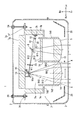
- FIG. 1 is a front view of a vehicle headlamp according to a first embodiment.
- the II sectional view which cut the vehicle headlamp of 1st Example horizontally.
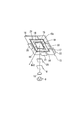
- the perspective view which looked at the scanning mechanism of 1st Example from the diagonally front of a reflective mirror.
- the vehicle headlamp according to the first embodiment will be described with reference to FIGS. 1 to 4.
- the vehicle headlamp 1 according to the first embodiment is an example of a right headlamp of a vehicle (not shown), and includes a lamp body 2, a front cover 3, and a headlamp unit 4.
- the lamp body 2 has an opening on the front side of the vehicle, and the front cover 3 is formed of a translucent resin, glass or the like, and is attached to the opening of the lamp body 2 so that the lamp chamber S is inside.
- Form The headlamp unit 4 shown in FIG. 1 is disposed inside the lamp chamber S by a metal support member 7.
- the headlamp unit 4 shown in FIGS. 1 and 2 includes a first headlamp unit 5, a second headlamp unit 6, a polarization generating unit 8 which is a reflective polarizing plate, and a light source 9 by a light emitting element such as an LED.
- the light lens 10 and the shutter 23 are provided respectively, and both are attached to the support member 7.
- the first headlamp unit 5 of FIG. 2A includes the liquid crystal panel 11 and the first projection lens 12
- the second headlamp unit 6 includes the scanning mechanism 13 and the second projection lens 14.
- the first projection lens 12 and the second projection lens 14 are transparent or semi-transparent plano-convex lenses in which the light exit surface is convex.
- the support member 7 is formed of metal and integrated with the bottom plate 7a, the side plates (7b, 7c) integrated with the left and right ends of the bottom plate 7a, and the tips of the side plates (7b, 7c). And a base plate 7e integrated with the base end of the side plate (7b, 7c).
- the lens support 7d is constituted by a first cylindrical portion 7d1, a second cylindrical portion 7d2, and a flange portion 7d3.
- the first cylindrical portion 7d1 on the left side and the second cylindrical portion 7d2 on the right side are integrated, and the first cylindrical portion 7d1 holds the liquid crystal panel 11 in the vicinity of the base end, and a convex surface in the vicinity of the tip
- the first projection lens 12 is fixed forward.
- the second projection lens 14 is fixed with the convex surface on the inner side in the vicinity of the tip end portion.
- the flange portion 7d3 is integrally formed on the outer periphery of the first cylindrical portion 7d1 and the second cylindrical portion 7d2, and is integrated with both of the side plate portions (7b, 7c).
- the base plate portion 7e is constituted by a screw fixing portion 7f and a heat dissipating portion 7g which is thicker than the screw fixing portion 7f.
- the light source 9 of FIG. 2 is configured by an LED light source or a laser light source, and is fixed to a light source support 7h provided on the left side plate 7b of the support member 7 to dissipate heat during lighting.
- the scanning mechanism 13 is a scanning device having a reflecting mirror 15 which can be tilted in two axial directions, and heat radiation of the support member 7 so that the reflecting surface 15 a of the reflecting mirror 15 faces both the light source 9 and the second projection lens 14. It is fixed to the front of part 7g.
- the condensing lens 10 is a transparent or semi-transparent plano-convex lens whose light exit surface has a convex shape, and is fixed to the bottom plate 7a in front of the light source 9, and focuses the light B1 from the light source 9 on the reflecting surface 15a. Focus on F1.
- the polarization generating unit 8 of FIG. 2 is disposed on the optical path of the light B1 from the light source 9 between the condensing lens 10 and the reflecting mirror 15 of the scanning mechanism 13 and for both the condensing lens 10 and the first projection lens 12. It mounts on bottom plate part 7a so that it may face.
- the polarization generating unit 8 includes a first polarizing unit 8 a that transmits S polarized light and reflects P polarized light, and a second polarizing unit 8 b that transmits P polarized light and reflects P polarized light. It is configured to be reciprocatively displaced up and down by a slide mechanism (not shown).
- a slide mechanism not shown in FIG.
- the first polarization unit 8a is disposed on the optical path of the light B1
- the second polarization unit 8b is disposed at a position deviated from the optical path of the light B1.
- the second polarizing part 8b is disposed on the optical path of the light B1 by sliding upward to the position of the first polarizing part 8a, and at this time, the first polarizing part 8a is separated from the optical path of the light B1.
- the first and second polarization parts (8a, 8b) can be switched between the arrangement on the light path or the outside of the light path by reciprocating displacement up and down in this manner.
- the first and second polarization sections (8a, 8b) transmit either S-polarization or P-polarization toward the scanning mechanism 13 when disposed on the optical path of the light B1, and the other is a first projection lens 12 Reflect towards.
- the polarization generation unit 8 shown in FIG. 2 separates the light B1 into a first polarization, that is, a reflected polarization B11 and a second polarization, that is, a transmission polarization B12.
- a first polarization that is, a reflected polarization B11
- a second polarization that is, a transmission polarization B12.
- the first polarization unit 8a is disposed on the optical path of the light B11
- the reflected polarization B11 is P polarization
- the transmission polarization B12 is S polarization
- the second polarization unit 8b is disposed on the optical path of the light B11.
- the reflected polarized light B11 is s-polarized light
- the transmitted polarized light B12 is p-polarized light.
- the reflected polarized light B11 is transmitted through the first projection lens 12 and the front cover 3 and the main light distribution patterns (La1, Lb1) shown in FIGS. 4A and 4B in front of the vehicle not shown. indicate.
- the first headlamp unit 5 improves the utilization efficiency of the polarization component by utilizing the polarization component which is originally not utilized by being reflected by the polarization generation unit 8 for forming the outer shape of the combined light distribution pattern.
- the shutter 23 of FIG. 2 is fixed to the bottom plate 7a of the support member 7 so as to be located on the optical path of the transmitted polarized light B12 generated by the polarized light generating unit 8 between the polarized light generating unit 8 and the reflecting mirror 15. Control is performed so as to pass or shield light at predetermined timing by control means (not shown).
- the headlamp unit 4 is screwed to the screw fixing portion 7 f of the base plate portion 7 e of the support member 7 by screwing three aiming screws 24 rotatably held by the lamp body 2 to the lamp body 2. It is supported so that it can tilt freely.
- an extension reflector 25 is provided which blinds the surroundings of the first projection lens 12 and the second projection lens 14 from the front.
- the scanning mechanism 13 shown in FIG. 2 is configured by a MEMS mirror or the like, and as shown in FIG. 3, the reflecting mirror 15, the base 16, the rotating body 17, a pair of first torsion bars 18, a pair of second torsion bars 19, a pair The permanent magnet 20, the pair of permanent magnets 21 and the terminal portion 22 are provided.
- the reflective surface 15 a is formed by subjecting the front surface of the reflective mirror 15 to a process such as silver deposition or plating.
- the plate-like rotating body 17 shown in FIG. 3 has a first coil (not shown) receiving power from the terminal portion 22 and is supported by the base 16 in a state where it can be tilted to the left and right by the pair of first torsion bars 18
- the reflecting mirror 15 has a second coil (not shown) supplied with power from the terminal 22, and is supported by the rotating body 17 so as to be vertically pivotable by a pair of second torsion bars 19 .
- the pivoting body 17 reciprocates and pivots around the axis of the first torsion bar 18 at high speed by the first coil controlled by the pair of permanent magnets 20 and the control mechanism (not shown) at high speed.
- the second coil which is controlled to be energized by the pair of permanent magnets 21 and the control mechanism (not shown), reciprocates and pivots around the axis of the second torsion bar 19 at high speed, and emits light from the light source 9 4 (a) and (b) in the range of the scanning area Sc1 of FIG. 4 (a) and (b) while reflecting the transmitted polarized light B12 transmitted through the polarized light generating unit 8 toward the second projection lens 14 by the reflecting surface 15a. .
- Transmission polarized light B12 shown in FIG. 2 is turned on and off with respect to the reflecting mirror 15 of the scanning mechanism 13 based on the passage of light by the shutter 23 or shielding control, and left and right scanning by the reflecting mirror 15 at high speed.
- Rods drawn at high speed horizontally on the left and right with position and length based on the lighting control of transmitted polarized light B12 are stacked vertically by repeating left and right scanning at high speed while shifting the vertical angle of the reflecting mirror 15 by small angle
- the auxiliary light distribution pattern (La2, Lb2) having a narrower range than the main light distribution pattern (La1, Lb1) is irradiated in a predetermined direction in front of the vehicle (not shown) Irradiate the spot with the object.
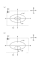
- the main light distribution pattern La1 by reflected polarized light B11 shown in FIG. 4A illuminates the front of the vehicle widely, and the auxiliary light distribution pattern La2 by transmitted polarized light B12 is hot by irradiating the central region inside the main light distribution pattern Lb1. Form a spot.
- the auxiliary light distribution pattern La2 irradiated to the central region by a spot is irradiated to a road sign or the like located obliquely upward from the front of an oncoming vehicle or a vehicle, but the transmission polarization B12 for displaying the auxiliary light distribution pattern La2 is light B11
- the first polarization unit 8a of the polarization generation unit 8 in the optical path of S, it becomes S polarization, and by sliding the polarization generation unit 8 to switch the first polarization unit 8a to the second polarization unit 8b, it becomes P polarization.
- the vehicle headlamp 1 irradiates the road with S-polarized light, the driver of the vehicle can easily see the shape of the road ahead. However, if the approaching oncoming vehicle or the obliquely upper road sign is irradiated with S-polarized light, the reflection is reflected. Light reflection may cause the driver of the vehicle to feel glare, and when the P-polarized light is irradiated to a predetermined illuminated object such as an oncoming vehicle or a road sign diagonally upward, the glare causes the driver to feel compared to S-polarization.
- the vehicle headlamp 1 reduces the first polarization unit 8a to the second polarization unit 8b and turns the spot irradiation light to the oncoming vehicle etc.
- the vehicle headlamp 1 can be used as a driver of the vehicle. It is possible to reduce the glare to be felt, and to secure the visibility of the road shape again by returning the spot irradiation light to S polarization by again using the first polarization section 8a after passing the oncoming vehicle etc. Can be
- the main light distribution pattern Lb1 by reflected polarized light B11 shown in FIG. 4B illuminates the front of the vehicle widely, and the auxiliary light distribution pattern Lb2 by transmitted polarized light B12 illuminates the vicinity of the lower end P1 inside the main light distribution pattern Lb1.
- the light directed to the front of the vehicle and obliquely downward may cause the driver of the vehicle to feel dazzling due to the reflection from the wet road surface when it illuminates the wet road surface in front of the vehicle and in the vicinity.
- the vehicle headlamp 1 switches the first polarizing portion 8 a to the second polarizing portion 8 b to make the wet road surface obliquely downward P
- the first polarization section 8a By spot irradiation with polarized light, it is possible to reduce glare received by the driver of the vehicle due to reflection, and after the road surface is dried, use the first polarization section 8a again to return the spot irradiation light to S polarization.
- the visibility of the road shape can be secured again.
- the vehicle headlamp 1 illuminates the object to be irradiated in a predetermined direction by pinpointing while selecting the polarized light to be irradiated according to the object to be irradiated or the wet road surface condition etc. between SP.
- it has the advantage of not causing the driver of the host vehicle to feel dazzling.
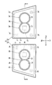
- the vehicle headlamp 31 of the second embodiment is configured by a first headlamp 32 on the right side and a second headlamp 33 on the left side.
- the first headlamp 32 changes the polarization generation unit 8 in the vehicle headlamp 1 of the first embodiment to a polarization generation unit 34, and mounts the transmittance variable unit 35 which is an output changing unit instead of the shutter 23.
- the configuration is common to the vehicle headlamp 1 of the first embodiment.
- the second headlamp 33 has a headlamp unit 36 ′ formed by forming the same component as the headlamp unit 36 of the first headlamp 32 in left-right symmetry except for the polarization generating unit 37.
- the reference numerals of the components of the headlight unit 36 ′ are shown by adding dashes to the reference numerals of the components of the headlight unit 36 except for the polarization generation unit 37.
- the polarization generation unit 34 of the first headlamp 32 shown in FIGS. 5 and 6 is a reflective polarizer having only one polarization unit that transmits S-polarization and reflects P-polarization.
- the polarization generation unit 34 is disposed on the optical path of the light B 2 from the light source 9 between the focusing lens 10 and the reflecting mirror 15 of the scanning mechanism 13 and faces both the focusing lens 10 and the first projection lens 12. It is fixed to the bottom plate 7a and does not have a switching mechanism of a plurality of polarization parts as in the polarization generation part 8 of the first embodiment.
- the transmittance changer 35 shown in FIG. 6 and the transmittance changer 35 ' which is an output changing unit are configured to be rotatable around axes (O1, O1') extending vertically, respectively, and controlled by control means (not shown) It is formed by a plate-like glass polarizer which is rotated by a driving mechanism.
- the plate-like glass polarizer is disposed in the irradiation range of S-polarized light B22 and P-polarized light B32 between the polarization generating section (34, 37) and the reflecting mirror (15, 15 '), respectively, and predetermined based on the incident angle. It transmits a part of the S-polarized light B22 and the P-polarized light B32 with transmittance, and reflects the remaining light.
- the incident angles of S-polarized light B22 and P-polarized light B32 to the glass polarizer change according to the rotation and stop position of the glass polarizer by the control means (not shown), and the transmittance variable devices (35, 35 ')
- the transmittances of the S-polarized light B22 and the P-polarized light B32 are changed from 0% to 100% or less.
- the position at which the transmittance variable device 35 is disposed may be the optical path of the polarization B 22, and is not limited to between the reflecting mirror 15 and the polarization generation unit 34.
- the position at which the transmittance variable unit 35 is disposed may also be the optical path of the polarization B 32, and is not limited to between the reflecting mirror 15 ′ and the polarization generation unit 37.
- the polarization generation unit 37 of the second headlamp 33 shown in FIGS. 5 and 6 transmits P-polarized light contrary to the polarization generation unit 34 and is reflective type polarization having only one polarization unit that reflects S-polarization. It is formed as a plate.
- the polarization generation unit 37 is disposed on the light path of the light B3 by the light source 9 'between the focusing lens 10' and the reflecting mirror 15 'of the scanning mechanism 13', and the focusing lens 10 'and the first projection lens 12'. It fixes to bottom plate part 7a 'so that both sides may be opposed.
- the headlamp unit 36 of the first headlamp 32 shown in FIGS. 5 and 6 includes a first headlamp unit 38, a second headlamp unit 39, a polarization generating unit 34 which is a reflective polarizing plate, an LED, etc.
- a light source 9 by a light emitting element, a condenser lens 10, and a transmittance variable device 35 are provided, respectively, which are all attached to the support member 7.
- a headlamp unit 36 'of the second headlamp includes a light source such as a first headlamp unit 38', a second headlamp unit 39 ', a polarization generating unit 37 which is a reflective polarizing plate, and an LED or the like.
- the first headlight unit (38, 38 ') has a liquid crystal panel (11, 11') and a first projection lens (12, 12 ') respectively, and the second headlight unit (39, 39') Each has a scanning mechanism (13, 13 ') and a second projection lens (14, 14').
- the first headlamp unit 38 of the first headlamp 32 shown in FIGS. 5 and 6 emits the light source 9 and causes the light B2 transmitted through the condenser lens 10 to be incident on the polarization generation unit 34 and polarized.
- the main light distribution pattern shown in FIGS. 4A and 4B is obtained by transmitting the first polarized light P21 reflected by the generation unit 34 to the liquid crystal panel 11, the first projection lens 12, and the front cover 3
- the second headlight unit 39 scans the S-polarized light B22 which is the second polarized light transmitted through the polarized light generating unit 34 and transmits it to the second projection lens 14 and the front cover 3 to form La1 and Lb1).
- the auxiliary light distribution patterns (La2, Lb2) shown in FIGS. 4A and 4B are formed, and predetermined illumination targets are spot-illuminated.
- the first headlamp unit 38 'of the second headlamp 33 is reverse to the first headlamp 32 in that light B3 of the light source 9' is reflected through polarization reflection by the polarization generator 37.
- the main light distribution patterns (La1, Lb1) shown in FIGS. 4 (a) and 4 (b) are formed by the S polarized light B31 which is the first polarized light generated, and the second headlight unit 39 '
- the auxiliary polarized light distribution patterns (La2, Lb2) for spot irradiation of a predetermined irradiation target are formed by scanning P polarized light B32 which is the second polarized light transmitted through 37.
- the S-polarized light B22 transmitted through the polarization generating portion 34 of the first headlamp 32 is transmitted through the transmittance variable device 35 capable of changing the transmittance of light to over 0% and up to 100%.
- the light flux density is adjusted by performing the P-polarization B 32 transmitted through the polarization generation unit 37 of the second headlight 33.
- the transmittance modifier 35 can also change the light transmittance to more than 0% and 100% or less.
- the luminous flux density is adjusted by transmitting '.
- the S polarized light B 22 and P polarized light B 32 which are the second polarized light transmitted through the transmittance variable unit (35, 35 ′) are synthesized in a state in which the luminous flux density is adjusted respectively, and are shown in FIGS. Form the auxiliary light distribution pattern (La2, Lb2) shown.
- the vehicle headlamp 31 shown in FIGS. 5 and 6 is synthesized by generating different reflected polarized light (first polarized light) and transmitted polarized light (second polarized light) in the first headlamp 32 and the second headlamp 33. While forming a light distribution pattern, the main light distribution patterns (La1, Lb1) shown in FIGS. 4 (a) and 4 (b) are displayed as S + P polarized light to illuminate the front of the vehicle as a whole brighter than in the first embodiment;
- the output (transmittance) of S-polarization B22 and P-polarization B32 for displaying the auxiliary light distribution patterns (La2, Lb2) can be freely adjusted in the range of more than 0% and 100% or less by the transmittance changer which is the output changer.
- the auxiliary light distribution pattern (La2, Lb2) consisting of only S polarized light + S polarized light or S polarized light alone or P polarized light containing the light flux in a predetermined ratio You can place a mark on a given illuminated object such as a road sign or a wet road surface. By preparative irradiation, it is possible to improve the visibility of the driver of the vehicle.
- the vehicle headlamp 1 has one of the first polarized light forming the main light distribution pattern (La1, Lb1) and the second polarized light forming the auxiliary light distribution pattern (La2, Lb2). Can be switched to S polarization and the other P polarization.
- the vehicle headlamp 31 of the second embodiment forms the main light distribution pattern (La1, Lb1) brightly by combining S polarized light + P polarized light and forms the auxiliary light distribution pattern (La2, Lb2) as light.
- the driver can be selected by the auxiliary light distribution pattern (La2, Lb2) including the optimum luminous flux content. It has the advantage of enabling optimal spot irradiation without remembering glare.
Landscapes
- Engineering & Computer Science (AREA)
- General Engineering & Computer Science (AREA)
- Non-Portable Lighting Devices Or Systems Thereof (AREA)
- Lighting Device Outwards From Vehicle And Optical Signal (AREA)
Abstract
車両用前照灯による光の利用効率を維持しつつ、自車の前照灯光による路上の照射対象物の視認性を向上させた車両用前照灯に関する。光源9からの光B1を前方に投射して配光パターンを形成する前照灯ユニット4を有する車両用前照灯1において、光源9からの光B1による第1及び第2の偏光(B11,B12)を生成する偏光生成部8と、第1の偏光B11による主配光パターン(La1,Lb1)を前方に表示する第1前照灯ユニット5と、第2の偏光B12を走査機構13で走査し、主配光パターン(La1,Lb1)よりも狭い範囲を照射する補助配光パターン(La2,Lb2)を前方に表示する第2型前照灯ユニット6と、を有することにした。
Description
対向車の前照灯光や湿潤路面からの照り返しによる反射グレア光等をドライバーに視認させにくくして自車の前照灯光を照射した路上の照射対象物の視認性を向上させた車両用前照灯に関する。
特許文献1には、車両前方の濡れた路面に光を照射し、所定の反射偏光のみをカットする偏光ガラスを透過させることでドライバーに塗れた路面の標識の視認しやすくした車両用前照灯に使用される眩惑防止装置が開示されている。
特許文献1の眩惑防止装置は、車両用前照灯から出射し、濡れた路面に反射されてドライバーに向かう反射光のうち路面標識の視認の妨げとなって利用出来ない偏光成分を遮断するため、反射光の利用効率を低下させる。また、車両用前照灯から濡れた路面、道路標識、対向車等の照射対象物に照射されてドライバーに向かう反射光の視認性は、路面状況や照射対象物によって異なると考えられるため、路面状況や照射対象物に反射光を生成してドライバーに視認させることが望ましい。
本願は、上記問題に鑑みて、車両用前照灯による光の利用効率を維持しつつ、対向車の前照灯光や湿潤路面からの照り返しによる反射グレア光等をドライバーに視認させにくくして自車の前照灯光を照射した路上の照射対象物の視認性を向上させた車両用前照灯を提供するものである。
光源からの光を前方に投射して配光パターンを形成する前照灯ユニットを有する車両用前照灯において、光源からの光による第1及び第2の偏光を生成する偏光生成部と、第1の偏光による主配光パターンを前方に表示する第1前照灯ユニットと、第2の偏光を走査機構で走査し、主配光パターンよりも狭い範囲を照射する補助配光パターンを前方に表示する第2前照灯ユニットと、を有するようにした。
(作用)濡れた路面等の路面状況や道路標識等の照射対象物の違いに応じて最適に生成された第2の偏光による補助配光パターンが、濡れた路面や道路標識等をスポット照射し、スポット照射に利用されない第1の偏光が、配光パターンの全体形状を形成する主配光パターンを照射する。
車両用前照灯において、前記第2の偏光の出力を増減させる出力変更部を備え、前記第2の偏光が、出力変更部によって出力されるS偏光と、出力変更部によって出力されるP偏光を合成した偏光による合成光となるようにした。
(作用)第2の偏光が、S偏光とP偏光の個別の出力に基づいて対向車の前照灯光や湿潤路面からの照り返しによる反射グレア光等、環境の相違に伴って適切な補助配光パターンを表示する。
車両用前照灯において、前記第2の前照灯ユニットが主配光パターンの中央に補助配光パターンを表示するようにした。
(作用)第2の前照灯ユニットが、対向車の前照灯光によるグレア光の視認性をドライバーにおいて低下させる。
車両用前照灯において、前記第2の前照灯ユニットが主配光パターンの下端部近傍に補助配光パターンを表示するようにした。
(作用)第2の前照灯ユニットが、湿潤路面からの照り返しによる反射グレア光の視認性をドライバーにおいて低下させる。
車両用前照灯によれば、車両用前照灯による光の利用効率が維持され、対向車の前照灯光や湿潤路面からの照り返しによる反射グレア光等が、ドライバーに視認されにくくなり、自車のドライバーにおける前照灯光を照射した路上の照射対象物の視認性が向上する。
また、車両前方の環境変化に左右されることなくドライバーにおけるグレア光の視認性を有効に低減して、ドライバーによる照射対象物毎の視認性を向上出来る。
また、対向車の前照灯光による眩しさをドライバーに感じにくくした上で車両前方の視認性を向上させる
また、湿潤路面からの照り返しによる反射グレア光による眩しさをドライバーに感じにくくした上で車両前方の視認性を向上させる。
また、湿潤路面からの照り返しによる反射グレア光による眩しさをドライバーに感じにくくした上で車両前方の視認性を向上させる。
以下、本発明の好適な実施形態を図1から図4に基づいて説明する。各図においては、車両用前照灯の各部や車両用前照灯の搭載車両のドライバーから見た道路の方向を(上方:下方:左方:右方:前方:後方=Up:Lo:Le:Ri:Fr:Re)として説明する。
図1から図4によって第1実施例の車両用前照灯を説明する。第1実施例の車両用前照灯1は、図示しない車両の右前照灯の一例であり、ランプボディ2と、前面カバー3と、前照灯ユニット4と、を備える。ランプボディ2は、車両の前方側に開口部を有し、前面カバー3は、透光性を有する樹脂やガラス等で形成され、ランプボディ2の開口部に取り付けられることによって内側に灯室Sを形成する。図1に示す前照灯ユニット4は、金属製の支持部材7によって灯室Sの内側に配置される。
図1及び図2の前照灯ユニット4は、第1前照灯ユニット5、第2前照灯ユニット6、反射型偏光板である偏光生成部8、LED等の発光素子による光源9、集光レンズ10及びシャッター23をそれぞれ有し、これらはいずれも支持部材7に取り付けられる。
図2(a)の第1前照灯ユニット5は、液晶パネル11と第1投影レンズ12を有し、第2前照灯ユニット6は、走査機構13と第2投影レンズ14を有する。第1投影レンズ12と第2投影レンズ14は、光の出射面を凸形状とした透明または半透明の平凸レンズである。
支持部材7は、金属で形成され、底板部7aと、底板部7aの左右端部にそれぞれ一体化された側板部(7b、7c)と、側板部(7b、7c)の先端に一体化されたレンズ支持部7dと、側板部(7b、7c)の基端に一体化された基礎板部7eと、を有する。レンズ支持部7dは、第1円筒部7d1、第2円筒部7d2、フランジ部7d3によって構成される。左側の第1円筒部7d1と右側の第2円筒部7d2は、一体化され、第1円筒部7d1は、基端部近傍の内側に液晶パネル11を保持し、先端部近傍の内側に凸面を前方に向けて第1投影レンズ12を固定される。第2円筒部7d2は、先端部近傍の内側に凸面を前方に向けて第2投影レンズ14を固定される。フランジ部7d3は、第1円筒部7d1及び第2円筒部7d2の外周に一体に形成されて、側板部(7b、7c)の双方に一体化される。基礎板部7eは、スクリュー固定部7fとスクリュー固定部7fよりも前後の奥行きが厚い放熱部7gによって構成される。
図2の光源9は、LED光源またはレーザー光源によって構成され、支持部材7の左側の側板部7bに設けられた光源支持部7hに固定されて点灯中の熱を放熱される。走査機構13は、2軸方向に傾動可能な反射鏡15を有するスキャンデバイスであり、反射鏡15の反射面15aを光源9と第2投影レンズ14の双方に対向させるように支持部材7の放熱部7gの前面に固定される。集光レンズ10は、光の出射面を凸形状とした透明または半透明の平凸レンズであり、光源9の前方で底板部7aに固定され、で光源9による光B1を反射面15a上の焦点F1に集光する。
図2の偏光生成部8は、集光レンズ10と走査機構13の反射鏡15の間において光源9による光B1の光路上に配置され、かつ集光レンズ10と第1投影レンズ12の双方に対向するように底板部7aに搭載される。偏光生成部8は、図1に示すようにS偏光を透光してP偏光を反射する第1偏光部8aと、P偏光を透光してP偏光を反射する第2偏光部8bを上下に並列させた形態を有し、図示しないスライド機構によって上下に往復変位可能に構成される。図1において、第1偏光部8aは、光B1の光路上に配置され、第2偏光部8bは光B1の光路から外れた位置に配置される。第2偏光部8bは、第1偏光部8aの位置まで上方にスライドすることで光B1の光路上に配置され、その際、第1偏光部8aは、光B1の光路から外れる。第1及び第2偏光部(8a,8b)は、このように上下に往復変位することで光路上または光路外の配置を切り換えられる。第1及び第2偏光部(8a、8b)は、光B1の光路上に配置された際にS偏光またはP偏光のいずれかを走査機構13に向けて透過させ、他方を第1投影レンズ12に向けて反射する。
図2に示す偏光生成部8は、光B1を第1の偏光である反射偏光B11と第2の偏光である透過偏光B12に分離する。第1偏光部8aが光B11の光路上に配置された場合、反射偏光B11はP偏光となり透過偏光B12はS偏光となる一方、第2偏光部8bが光B11の光路上に配置され場合、反射偏光B11は、S偏光となり透過偏光B12はP偏光となる。
図2に示す通り、反射偏光B11は、第1投影レンズ12及び前面カバー3を透過して図示しない車両の前方に図4(a)(b)に示す主配光パターン(La1,Lb1)を表示する。第1前照灯ユニット5は、偏光生成部8に反射されることで本来なら利用されない偏光成分を合成配光パターンの外形形成に利用することで偏光成分の利用効率を向上させている。
また、図2のシャッター23は、偏光生成部8と反射鏡15の間で偏光生成部8によって生成される透過偏光B12の光路上に位置するように支持部材7の底板部7aに固定され、図示しない制御手段によって所定のタイミングで光を通過または遮蔽するように制御される。前照灯ユニット4は、ランプボディ2に回動自在に保持された3つのエイミングスクリュー24を支持部材7の基礎板部7eのスクリュー固定部7fに螺着されることにより、ランプボディ2に対して傾動自在に支持される。また、灯室S内には、第1投影レンズ12及び第2投影レンズ14の周囲を前方から目隠しするエクステンションリフレクター25が設けられる。
図2に示す走査機構13は、MEMSミラーなどによって構成され、図3に示すように反射鏡15、ベース16、回動体17、一対の第1トーションバー18、一対の第2トーションバー19、一対の永久磁石20,一対の永久磁石21及び端子部22を有する。反射面15aは、反射鏡15の前面に銀蒸着やメッキなどの処理を施すことで形成される。
図3の板状の回動体17は、端子部22から給電を受ける第1のコイル(図示せず)を有し、一対の第1トーションバー18によって左右に傾動可能な状態でベース16に支持され、反射鏡15は、端子部22から給電を受ける第2のコイル(図示せず)を有し、一対の第2トーションバー19によって上下に回動可能な状態で回動体17に支持される。回動体17は、一対の永久磁石20と制御機構(図示せず)によって通電制御される第1コイルによって第1トーションバー18の軸線を中心として左右に高速で往復揺動回転し、反射鏡15もまた、一対の永久磁石21と制御機構(図示せず)によって通電制御される第2コイルによって第2トーションバー19の軸線を中心として上下に高速で往復揺動回転し、光源9から出射して偏光生成部8を透過した透過偏光B12を反射面15aによって第2投影レンズ14に向けて反射しつつ、図4(a)(b)の走査領域Sc1の範囲内で所定の方向に走査する。
図2に示す透過偏光B12は、シャッター23による光の通過または遮蔽制御に基づいて走査機構13の反射鏡15に対して点消灯し、反射鏡15によって左右に高速で走査されることで左右に伸びる点消灯に基づいた長さの棒線を所定の位置に描画する。透過偏光B12の点灯制御に基づいた位置と長さで左右に高速で描画される棒線は、反射鏡15の上下角を微小角ずつずらされながら左右の走査を高速繰り返して上下に積層されることにより、図4(a)(b)に示す、主配光パターン(La1,Lb1)よりも範囲の狭い補助配光パターン(La2,Lb2)を車両(図示せず)の前方の所定の照射対象物にスポット照射する。
図4(a)に示す反射偏光B11による主配光パターンLa1は、車両前方を広く照らし、透過偏光B12による補助配光パターンLa2は、主配光パターンLb1の内側で中央領域を照射してホットスポットを形成する。中央領域にスポット照射された補助配光パターンLa2は、対向車や車両の前方から斜め上方に位置する道路標識などに照射されるが、補助配光パターンLa2を表示する透過偏光B12は、光B11の光路に偏光生成部8の第1偏光部8aを配置することでS偏光となり、偏光生成部8をスライドさせて第1偏光部8aを第2偏光部8bに切り換えることでP偏光になる。
仮に、車両用前照灯1がS偏光を道路に照射すると自車両のドライバーに前方の道路形状を視認させやすい反面、近づいてくる対向車や斜め上方の道路標識にS偏光を照射すると、反射光による照り返しが自車両ドライバーに眩しさを感じさせる場合があり、P偏光を対向車や斜め上方の道路標識等の所定の照射対象物に照射すると、S偏光に比べてドライバーに感じさせる眩しさが低減される場合において、車両用前照灯1は、第1偏光部8aを第2偏光部8bに切り換えて対向車等へのスポット照射光をP偏光にすることで、自車両のドライバーに感じされる眩しさを低減させることが出来、対向車等の通過後に再び第1偏光部8aを再度利用してスポット照射光をS偏光に戻すことで、道路形状の視認性を再び確保することが出来る。
図4(b)に示す反射偏光B11による主配光パターンLb1は、車両前方を広く照らし、透過偏光B12による補助配光パターンLb2は、主配光パターンLb1の内側の下端部P1近傍を照射してホットスポットを形成する。車両前方かつ斜め下方に向けられる光は、車両前方かつ近傍の湿潤路面を照らした場合において、湿潤路面からの照り返しによって自車両のドライバーに眩しさを感じさせる場合がある。
S偏光は、湿潤路面に照射されるとP偏光よりも強く反射されるため、車両用前照灯1は、第1偏光部8aを第2偏光部8bに切り換えて斜め下方の湿潤路面にP偏光をスポット照射することで、照り返しによって自車両のドライバーが受ける眩しさを低減させることが出来、路面が乾いた後に再び第1偏光部8aを再度利用してスポット照射光をS偏光に戻すことで、道路形状の視認性を再び確保することが出来る。
このように本実施例の車両用前照灯1は、照射対象物や湿潤化した路面状況等によって照射される偏光をS-P間で選択しつつ所定方向の照射対象物をピンポイントで照明しつつ、自車両のドライバーに眩しさを感じさせないという利点を有する。
次に図5,図6により第2実施例の車両用前照灯31を説明する。第2実施例の車両用前照灯31は、右側の第1前照灯32及び左側の第2前照灯33によって構成される。第1前照灯32は、第1実施例の車両用前照灯1における偏光生成部8を偏光生成部34に変更し、シャッター23の代わりに出力変更部である透過率可変器35を搭載した他、第1実施例の車両用前照灯1と共通した構成を有する。第2前照灯33は、偏光生成部37を除き、第1前照灯32の前照灯ユニット36と同一の構成物品を左右対称に形成してなる前照灯ユニット36’を有する。前照灯ユニット36’の構成物品の符号は、偏光生成部37を除き前照灯ユニット36の各構成物品の符号にダッシュをつけて表すこととする。
図5及び図6に示す第1前照灯32の偏光生成部34は、S偏光を透過し、かつP偏光を反射する一の偏光部のみを有する反射型偏光板である。偏光生成部34は、集光レンズ10と走査機構13の反射鏡15の間において光源9による光B2の光路上に配置され、かつ集光レンズ10と第1投影レンズ12の双方に対向するように底板部7aに固定され、第1実施例の偏光生成部8のように複数の偏光部の切替機構を持たない。
図6に示す透過率可変器35と、出力変更部である透過率可変器35’は、それぞれ上下に伸びる軸線(O1,O1’)周りに回動可能に構成され、図示しない制御手段で制御される駆動機構によって回動する板状のガラス偏光子によって形成される。板状のガラス偏光子は、それぞれ偏光生成部(34,37)と反射鏡(15,15’)の間においてS偏光B22及びP偏光B32の照射範囲に配置され、入射角に基づいた所定の透過率でS偏光B22及びP偏光B32の一部を透過させると共に残りの光を反射する。ガラス偏光子へのS偏光B22及びP偏光B32の入射角は、図示しない制御手段によるガラス偏光子の回動及び停止位置によって変化し、透過率可変器(35,35’)は、それぞれガラス偏光子の回転制御によってS偏光B22及びP偏光B32の透過率を0%を越え100%以下まで変化させる。尚、透過率可変器35を配置する位置は、偏光B22の光路上であればよく、反射鏡15と偏光生成部34とに間に限られない。透過率可変器35’を配置する位置もまた、偏光B32の光路上であればよく、反射鏡15’と偏光生成部37の間に限られない。
図5及び図6に示す第2前照灯33の偏光生成部37は、偏光生成部34とは逆にP偏光を透過し、かつS偏光を反射する一の偏光部のみを有する反射型偏光板として形成される。偏光生成部37は、集光レンズ10’と走査機構13’の反射鏡15’の間において光源9’による光B3の光路上に配置され、かつ集光レンズ10’と第1投影レンズ12’の双方に対向するように底板部7a’に固定される。
図5及び図6の第1前照灯32の前照灯ユニット36は、第1前照灯ユニット38、第2前照灯ユニット39、反射型偏光板である偏光生成部34、LED等の発光素子による光源9、集光レンズ10及び透過率可変器35をそれぞれ有し、これらはいずれも支持部材7に取り付けられる。第2前照灯の前照灯ユニット36’は、第1前照灯ユニット38’、第2前照灯ユニット39’、反射型偏光板である偏光生成部37、LED等の発光素子による光源9’、集光レンズ10’及び透過率可変器35’をそれぞれ有し、これらはいずれも支持部材7’に取り付けられる。第1前照灯ユニット(38、38’)は、それぞれ液晶パネル(11、11’)と第1投影レンズ(12、12’)を有し、第2前照灯ユニット(39、39’)は、それぞれ走査機構(13、13’)と第2投影レンズ(14、14’)を有する。
図5及び図6に示す第1前照灯32の第1前照灯ユニット38は、光源9を出射して、集光レンズ10を透過させた光B2を偏光生成部34に入射させ、偏光生成部34によって反射された第1の偏光であるP偏光B21を液晶パネル11、第1投影レンズ12及び前面カバー3に透過させることで図4(a)(b)に示す主配光パターン(La1、Lb1)を形成し、第2前照灯ユニット39は、偏光生成部34を透過した第2の偏光であるS偏光B22を走査して第2投影レンズ14及び前面カバー3に透過させることで図4(a)(b)に示す補助配光パターン(La2、Lb2)を形成し、所定の照射対象物をスポット照明する。
図5、図6において、第2前照灯33の第1前照灯ユニット38’は、第1前照灯32とは逆に光源9’の光B3から偏光生成部37による偏光反射を介して生成された第1の偏光であるS偏光B31によって図4(a)(b)に示す主配光パターン(La1、Lb1)を形成し、第2前照灯ユニット39’は、偏光生成部37を透過した第2の偏光であるP偏光B32を走査して所定の照射対象物をスポット照射する補助配光パターン(La2、Lb2)を形成する。
また、図5、図6において第1前照灯32の偏光生成部34を透過したS偏光B22は、光の透過率を0%を越え100%以下まで変更可能な透過率可変器35を透過することで光束密度を調整され、第2前照灯33の偏光生成部37を透過したP偏光B32もまた、光の透過率を0%を越え100%以下まで変更可能な透過率可変器35’を透過することで光束密度を調整される。透過率可変器(35,35’)を透過した第2の偏光であるS偏光B22及びP偏光B32は、光束密度をそれぞれ調節された状態で合成されて、図4(a)(b)に示される補助配光パターン(La2、Lb2)を形成する。
図5,図6の車両用前照灯31は、第1前照灯32と第2前照灯33で異なる反射偏光(第1の偏光)及び透過偏光(第2偏光)を生成して合成配光パターンを形成し、図4(a)(b)に示す主配光パターン(La1、Lb1)をS+P偏光で表示して第1実施例よりも車両の前方を全体的に明るく照らすと共に、補助配光パターン(La2、Lb2)を表示するS偏光B22と、P偏光B32の出力(透過率)を出力変更部である透過率可変器でそれぞれ0%を越え100%以下となる範囲で自在に変化させ、所定の割合で光束が含有されるS偏光+P偏光の合成偏光、S偏光のみまたはP偏光のみからなる補助配光パターン(La2、Lb2)を所定の対向車、車両の斜め前方の道路標識または湿潤路面等の所定の照射対象物にスポット照射することで、自車両のドライバーの視認性を向上させることが出来る。
第1実施例の車両用前照灯1は、主配光パターン(La1、Lb1)を形成する第1の偏光と、補助配光パターン(La2、Lb2)を形成する第2の偏光について、片方をS偏光とし、もう片方をP偏光とするように切り換えることしか出来ない。しかし、第2実施例の車両用前照灯31は、主配光パターン(La1、Lb1)をS偏光+P偏光の合成によって明るく形成するとともに、補助配光パターン(La2、Lb2)の形成光に含まれるS偏光及びP偏光の光束含有率を照射対象物の変化や路面状況の変化に基づいて自在に変更出来るため、最適な光束含有率を含む補助配光パターン(La2、Lb2)によってドライバーが眩しさを覚えない最適なスポット照射が可能になるという利点を有する。
本国際出願は、2017年7月14日に出願された日本国特許出願である特願2017-137798号に基づく優先権を主張するものであり、当該日本国特許出願である特願2017-137798号の全内容は、本国際出願に参照することにより援用される。
本発明の特定の実施の形態についての上記説明は、例示を目的として提示したものである。それらは、網羅的であったり、記載した形態そのままに本発明を制限したりすることを意図したものではない。数多くの変形や変更が、上記の記載内容に照らして可能であることは当業者に自明である。
1 車両用前照灯
4 前照灯ユニット
5 第1前照灯ユニット
6 第2前照灯ユニット
8 偏光生成部
13 走査機構
31 車両用前照灯
34 偏光生成部
37 偏光生成部
35、35’ 出力変更部である透過率可変器
36、36’ 前照灯ユニット
38、38’ 第1前照灯ユニット
39、39’ 第2前照灯ユニット
B1~B3 光源からの光
B11、B21、B31 第1の偏光
B12、B22、B32 第2の偏光
La1、Lb1 主配光パターン
La2、Lb2 補助配光パターン
4 前照灯ユニット
5 第1前照灯ユニット
6 第2前照灯ユニット
8 偏光生成部
13 走査機構
31 車両用前照灯
34 偏光生成部
37 偏光生成部
35、35’ 出力変更部である透過率可変器
36、36’ 前照灯ユニット
38、38’ 第1前照灯ユニット
39、39’ 第2前照灯ユニット
B1~B3 光源からの光
B11、B21、B31 第1の偏光
B12、B22、B32 第2の偏光
La1、Lb1 主配光パターン
La2、Lb2 補助配光パターン
Claims (4)
- 光源からの光を前方に投射して配光パターンを形成する前照灯ユニットを有する車両用前照灯において、
光源からの光による第1及び第2の偏光を生成する偏光生成部と、
第1の偏光による主配光パターンを前方に表示する第1前照灯ユニットと、
第2の偏光を走査機構で走査し、主配光パターンよりも狭い範囲を照射する補助配光パターンを前方に表示する第2前照灯ユニットと、を有することを特徴とする車両用前照灯。 - 前記第2の偏光の出力を増減させる出力変更部を備え、
前記第2の偏光は、出力変更部によって出力されるS偏光と、出力変更部によって出力されるP偏光による合成光であることを特徴とする、請求項1に記載の車両用前照灯。 - 前記第2前照灯ユニットが主配光パターンの中央に補助配光パターンを表示することを特徴とする、請求項1または2に記載の車両用前照灯。
- 前記第2前照灯ユニットが主配光パターンの下端部近傍に補助配光パターンを表示することを特徴とする、請求項1または2に記載の車両用前照灯。
Priority Applications (2)
| Application Number | Priority Date | Filing Date | Title |
|---|---|---|---|
| CN201880044086.4A CN110809694B (zh) | 2017-07-14 | 2018-07-06 | 车辆用前照灯 |
| US16/629,060 US10823352B2 (en) | 2017-07-14 | 2018-07-06 | Vehicle headlight with polarized light generator |
Applications Claiming Priority (2)
| Application Number | Priority Date | Filing Date | Title |
|---|---|---|---|
| JP2017137798A JP6901335B2 (ja) | 2017-07-14 | 2017-07-14 | 車両用前照灯 |
| JP2017-137798 | 2017-07-14 |
Publications (1)
| Publication Number | Publication Date |
|---|---|
| WO2019013113A1 true WO2019013113A1 (ja) | 2019-01-17 |
Family
ID=65001683
Family Applications (1)
| Application Number | Title | Priority Date | Filing Date |
|---|---|---|---|
| PCT/JP2018/025624 Ceased WO2019013113A1 (ja) | 2017-07-14 | 2018-07-06 | 車両用前照灯 |
Country Status (4)
| Country | Link |
|---|---|
| US (1) | US10823352B2 (ja) |
| JP (1) | JP6901335B2 (ja) |
| CN (1) | CN110809694B (ja) |
| WO (1) | WO2019013113A1 (ja) |
Families Citing this family (1)
| Publication number | Priority date | Publication date | Assignee | Title |
|---|---|---|---|---|
| KR20210125761A (ko) * | 2020-04-09 | 2021-10-19 | 현대모비스 주식회사 | 자동차용 램프 및 그 램프를 포함하는 자동차 |
Citations (2)
| Publication number | Priority date | Publication date | Assignee | Title |
|---|---|---|---|---|
| JP2003297116A (ja) * | 2002-04-05 | 2003-10-17 | Honda Motor Co Ltd | 投光装置 |
| WO2011129105A1 (ja) * | 2010-04-13 | 2011-10-20 | 株式会社小糸製作所 | 光学ユニット、車両監視装置および障害物検出装置 |
Family Cites Families (5)
| Publication number | Priority date | Publication date | Assignee | Title |
|---|---|---|---|---|
| JP2005041443A (ja) | 2003-07-25 | 2005-02-17 | Asmo Co Ltd | 眩惑防止装置 |
| US10174894B2 (en) * | 2014-12-11 | 2019-01-08 | Stanley Electric Co., Ltd. | Vehicle headlamp unit and vehicle headlamp system |
| JP6422361B2 (ja) * | 2015-02-13 | 2018-11-14 | スタンレー電気株式会社 | 車両用前照灯ユニット、車両用前照灯システム |
| JP6564568B2 (ja) * | 2014-12-11 | 2019-08-21 | スタンレー電気株式会社 | 車両用前照灯ユニット、車両用前照灯システム |
| CN106939992A (zh) * | 2017-05-14 | 2017-07-11 | 上海小糸车灯有限公司 | 一种基于pbs分光器的车灯系统 |
-
2017
- 2017-07-14 JP JP2017137798A patent/JP6901335B2/ja active Active
-
2018
- 2018-07-06 WO PCT/JP2018/025624 patent/WO2019013113A1/ja not_active Ceased
- 2018-07-06 US US16/629,060 patent/US10823352B2/en not_active Expired - Fee Related
- 2018-07-06 CN CN201880044086.4A patent/CN110809694B/zh not_active Expired - Fee Related
Patent Citations (2)
| Publication number | Priority date | Publication date | Assignee | Title |
|---|---|---|---|---|
| JP2003297116A (ja) * | 2002-04-05 | 2003-10-17 | Honda Motor Co Ltd | 投光装置 |
| WO2011129105A1 (ja) * | 2010-04-13 | 2011-10-20 | 株式会社小糸製作所 | 光学ユニット、車両監視装置および障害物検出装置 |
Also Published As
| Publication number | Publication date |
|---|---|
| CN110809694B (zh) | 2022-04-01 |
| JP6901335B2 (ja) | 2021-07-14 |
| CN110809694A (zh) | 2020-02-18 |
| US20200191350A1 (en) | 2020-06-18 |
| JP2019018669A (ja) | 2019-02-07 |
| US10823352B2 (en) | 2020-11-03 |
Similar Documents
| Publication | Publication Date | Title |
|---|---|---|
| JP5248833B2 (ja) | 車両用照明灯具 | |
| JP6114653B2 (ja) | 車両用灯具 | |
| US10794559B2 (en) | Vehicle lamp and vehicle having the same | |
| JP6174337B2 (ja) | 車両用灯具 | |
| US7575352B2 (en) | Vehicular headlamp | |
| JP6140700B2 (ja) | 車両用灯具およびその制御方法 | |
| JP6952541B2 (ja) | 車両用前照灯 | |
| US8573819B2 (en) | Vehicle headlamp and vehicle headlamp apparatus | |
| CN107366865B (zh) | 双光路形成型投射光学系统、投射前照灯和车辆 | |
| JP6796993B2 (ja) | 光学ユニット | |
| JP2013097886A (ja) | 車輌用前照灯 | |
| JP5390364B2 (ja) | 車両用ヘッドランプ | |
| JP2019021481A (ja) | 車両用灯具 | |
| US20160161074A1 (en) | Lamp unit | |
| JP7607566B2 (ja) | 車両用灯具 | |
| JP6422361B2 (ja) | 車両用前照灯ユニット、車両用前照灯システム | |
| WO2019069672A1 (ja) | 車両用前照灯 | |
| JP2020013697A (ja) | 車両用灯具 | |
| WO2019013113A1 (ja) | 車両用前照灯 | |
| JP6683149B2 (ja) | ヘッドアップディスプレイ装置 | |
| WO2018082224A1 (zh) | 一种高分辨率汽车大灯光学模组及其高分辨率远光照明控制方法 | |
| JP2015223887A (ja) | 車両用灯具システム | |
| JP5869807B2 (ja) | プロジェクタ型ヘッドランプ | |
| JP2012226997A (ja) | 車輌用前照灯 | |
| JP2018195421A (ja) | 光学ユニット |
Legal Events
| Date | Code | Title | Description |
|---|---|---|---|
| 121 | Ep: the epo has been informed by wipo that ep was designated in this application |
Ref document number: 18832259 Country of ref document: EP Kind code of ref document: A1 |
|
| NENP | Non-entry into the national phase |
Ref country code: DE |
|
| 122 | Ep: pct application non-entry in european phase |
Ref document number: 18832259 Country of ref document: EP Kind code of ref document: A1 |