WO2019013061A1 - 作業機械システムおよび制御方法 - Google Patents
作業機械システムおよび制御方法 Download PDFInfo
- Publication number
- WO2019013061A1 WO2019013061A1 PCT/JP2018/025317 JP2018025317W WO2019013061A1 WO 2019013061 A1 WO2019013061 A1 WO 2019013061A1 JP 2018025317 W JP2018025317 W JP 2018025317W WO 2019013061 A1 WO2019013061 A1 WO 2019013061A1
- Authority
- WO
- WIPO (PCT)
- Prior art keywords
- data
- work machine
- server device
- basic data
- server
- Prior art date
Links
Images


Classifications
-
- E—FIXED CONSTRUCTIONS
- E02—HYDRAULIC ENGINEERING; FOUNDATIONS; SOIL SHIFTING
- E02F—DREDGING; SOIL-SHIFTING
- E02F9/00—Component parts of dredgers or soil-shifting machines, not restricted to one of the kinds covered by groups E02F3/00 - E02F7/00
- E02F9/20—Drives; Control devices
- E02F9/2025—Particular purposes of control systems not otherwise provided for
- E02F9/2054—Fleet management
-
- E—FIXED CONSTRUCTIONS
- E02—HYDRAULIC ENGINEERING; FOUNDATIONS; SOIL SHIFTING
- E02F—DREDGING; SOIL-SHIFTING
- E02F3/00—Dredgers; Soil-shifting machines
- E02F3/04—Dredgers; Soil-shifting machines mechanically-driven
- E02F3/28—Dredgers; Soil-shifting machines mechanically-driven with digging tools mounted on a dipper- or bucket-arm, i.e. there is either one arm or a pair of arms, e.g. dippers, buckets
- E02F3/36—Component parts
- E02F3/42—Drives for dippers, buckets, dipper-arms or bucket-arms
- E02F3/43—Control of dipper or bucket position; Control of sequence of drive operations
- E02F3/435—Control of dipper or bucket position; Control of sequence of drive operations for dipper-arms, backhoes or the like
-
- E—FIXED CONSTRUCTIONS
- E02—HYDRAULIC ENGINEERING; FOUNDATIONS; SOIL SHIFTING
- E02F—DREDGING; SOIL-SHIFTING
- E02F9/00—Component parts of dredgers or soil-shifting machines, not restricted to one of the kinds covered by groups E02F3/00 - E02F7/00
- E02F9/26—Indicating devices
- E02F9/264—Sensors and their calibration for indicating the position of the work tool
-
- E—FIXED CONSTRUCTIONS
- E02—HYDRAULIC ENGINEERING; FOUNDATIONS; SOIL SHIFTING
- E02F—DREDGING; SOIL-SHIFTING
- E02F3/00—Dredgers; Soil-shifting machines
- E02F3/04—Dredgers; Soil-shifting machines mechanically-driven
- E02F3/28—Dredgers; Soil-shifting machines mechanically-driven with digging tools mounted on a dipper- or bucket-arm, i.e. there is either one arm or a pair of arms, e.g. dippers, buckets
- E02F3/30—Dredgers; Soil-shifting machines mechanically-driven with digging tools mounted on a dipper- or bucket-arm, i.e. there is either one arm or a pair of arms, e.g. dippers, buckets with a dipper-arm pivoted on a cantilever beam, i.e. boom
- E02F3/32—Dredgers; Soil-shifting machines mechanically-driven with digging tools mounted on a dipper- or bucket-arm, i.e. there is either one arm or a pair of arms, e.g. dippers, buckets with a dipper-arm pivoted on a cantilever beam, i.e. boom working downwardly and towards the machine, e.g. with backhoes
-
- E—FIXED CONSTRUCTIONS
- E02—HYDRAULIC ENGINEERING; FOUNDATIONS; SOIL SHIFTING
- E02F—DREDGING; SOIL-SHIFTING
- E02F3/00—Dredgers; Soil-shifting machines
- E02F3/04—Dredgers; Soil-shifting machines mechanically-driven
- E02F3/28—Dredgers; Soil-shifting machines mechanically-driven with digging tools mounted on a dipper- or bucket-arm, i.e. there is either one arm or a pair of arms, e.g. dippers, buckets
- E02F3/36—Component parts
- E02F3/38—Cantilever beams, i.e. booms;, e.g. manufacturing processes, forms, geometry or materials used for booms; Dipper-arms, e.g. manufacturing processes, forms, geometry or materials used for dipper-arms; Bucket-arms
-
- E—FIXED CONSTRUCTIONS
- E02—HYDRAULIC ENGINEERING; FOUNDATIONS; SOIL SHIFTING
- E02F—DREDGING; SOIL-SHIFTING
- E02F9/00—Component parts of dredgers or soil-shifting machines, not restricted to one of the kinds covered by groups E02F3/00 - E02F7/00
- E02F9/26—Indicating devices
-
- E—FIXED CONSTRUCTIONS
- E02—HYDRAULIC ENGINEERING; FOUNDATIONS; SOIL SHIFTING
- E02F—DREDGING; SOIL-SHIFTING
- E02F9/00—Component parts of dredgers or soil-shifting machines, not restricted to one of the kinds covered by groups E02F3/00 - E02F7/00
- E02F9/26—Indicating devices
- E02F9/267—Diagnosing or detecting failure of vehicles
-
- E—FIXED CONSTRUCTIONS
- E02—HYDRAULIC ENGINEERING; FOUNDATIONS; SOIL SHIFTING
- E02F—DREDGING; SOIL-SHIFTING
- E02F9/00—Component parts of dredgers or soil-shifting machines, not restricted to one of the kinds covered by groups E02F3/00 - E02F7/00
- E02F9/28—Small metalwork for digging elements, e.g. teeth scraper bits
- E02F9/2808—Teeth
Definitions
- the present invention relates to a work machine system and control method.
- An object of the present invention is to provide a working machine system and a control method capable of quickly acquiring data used for calculation of a cutting edge position.
- a work machine system includes a work machine having a work machine including a bucket, and a server capable of communicating with the work machine.
- the work machine transmits the identification number associated with the work machine to the server.
- the server has an acquisition unit that acquires basic data used to calculate the blade edge position of the bucket based on the identification information, and a transmission unit that transmits the acquired basic data to the work machine.
- a working machine system having a server device and a working machine will be described with reference to the drawings.
- the working vehicle as an example of the said working machine is demonstrated below.
- a hydraulic shovel will be described as an example.
- an information and communication technology (ICT) hydraulic shovel will be described as an example.
- the server device receives the machine number from the work vehicle.
- the server device acquires, from the data table stored in the server device, a plurality of data used by the work vehicle for calculating the cutting edge position of the bucket based on the machine number.
- the server device transmits the plurality of acquired data to the work vehicle.
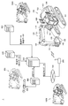
- FIG. 1 is a diagram showing a schematic configuration of a work machine system based on the embodiment.
- the work machine system 1 includes a plurality of work vehicles 100, 100A, 100B, a plurality of server devices 200, 400, 500, 600, a camera 300, and a transceiver 800.
- the number of work vehicles is not limited to three.
- the camera 300 and the server device 400 are communicably connected.
- the server device 200 and the server devices 400, 500, and 600 are communicably connected.
- the server apparatus 200 is communicably connected to the transceiver 800 via a network 700 such as the Internet.
- the server device 200 is an example of the “server” in the present invention.
- Work vehicle 100 is an example of the “work machine” in the present invention.
- the work vehicle 100 includes a traveling body 101, a revolving unit 103, a work implement 104, and a receiving antenna 109 for the Global Positioning Satellite System (GNSS). Mainly.
- the work vehicle main body is configured of a traveling body 101 and a revolving body 103.
- the traveling body 101 has a pair of left and right crawler belts.
- the pivoting body 103 is pivotally mounted via a pivoting mechanism on the upper portion of the traveling body 101.
- the work implement 104 is axially supported so as to be operable in the vertical direction in the swing body 103, and performs work such as excavation of earth and sand.
- Work implement 104 includes boom 110, arm 120, bucket 130, boom cylinder 111, arm cylinder 121, and bucket cylinder 131 as component parts.
- the base of the boom 110 is movably connected to the rotating body 103.
- the arm 120 is movably connected to the tip of the boom 110.
- the bucket 130 is movably connected to the tip of the arm 120.
- the swing body 103 includes a driver's cab 108 and a handrail 107.
- the receiving antenna 109 is attached to the handrail 107.
- the boom 110 is driven by the boom cylinder 111.
- the arm 120 is driven by the arm cylinder 121.
- the bucket 130 is driven by the bucket cylinder 131.
- Work implement 104 of work vehicle 100 is an example of the “work implement” in the present invention.
- the bucket 130 of the work vehicle 100 is an example of the "bucket" of the present invention.
- work vehicles 100A and 100B have the same configuration as that of work vehicle 100, the configurations of work vehicles 100A and 100B will not be repeatedly described. The following description will focus on the work vehicle 100 among the plurality of work vehicles 100, 100A, and 100B.
- the camera 300 is a camera for three-dimensional measurement.
- the camera 300 has a dual camera sensor.
- the camera 300 images in advance the work vehicle 100 to which reflectors are attached at a plurality of predetermined positions, and sends the image data obtained by the imaging to the server device 400.
- the reflector is attached to the receiving antenna 109, the cutting edge of the bucket 130, the foot pin 141, and the bucket pin 142.
- the server device 400 software for acquiring three-dimensional data (3D data) is installed in advance.
- the server apparatus 400 calculates three-dimensional coordinate data of the reflector (hereinafter also referred to as “measurement data”) based on the three-dimensional image data sent from the camera 300.
- measurement data is obtained by image data.
- the server device 400 calculates three-dimensional coordinate data of the reflector for each of the plurality of work vehicles 100.
- the server device 400 stores the management number associated with the machine number of the work vehicle and the coordinate data in association with each other.
- the server device 400 associates coordinate data with a management number and transmits it to the server device 200.
- the management number is an identification number, and a specific example thereof will be described later (FIG. 5, FIG. 6).
- the server device 200 calculates the actual size data from the measurement data as an example, but the present invention is not limited to this.
- the server device 400 may calculate the actual size data from the measurement data. In this case, the server device 400 may transmit the actual size data to the server device 200 instead of the measurement data.
- the server devices 500 and 600 store manufacturing data of the components included in the work machine 104 in association with the control number associated with the machine number of the work vehicle.
- the manufacturing data includes actual machining data at the time of machining (hereinafter also referred to as “processing data”) and inspection data obtained by inspecting a product.
- the machining data is data representing an actual machining position at the time of machining and is different from the design data. Machining is typically performed by a machine tool not shown.
- the server device 500 stores processing data of components included in the work machine 104 such as the boom 110 and the arm 120 in association with a management number.
- the server device 500 stores, for example, the position (coordinate data) of the pin hole as the processing data described above.
- the server device 500 In response to a request from the server device 200, the server device 500 associates coordinate data as processing data with a management number and transmits it to the server device 200.
- the server device 600 associates inspection data of components included in the working machine 104 such as the boom cylinder 111, the arm cylinder 121, the bucket cylinder 131, etc. with the machine number of the work vehicle 100 to which these cylinders are to be attached. It is stored in association with the assigned control number.
- the server device 600 stores measured data as the inspection data.
- the server device 600 stores, as the above-described actual measurement data, a cylinder length when these cylinders are most extended and a cylinder length when the cylinders are most contracted.
- the server device 600 transmits actual measurement data as inspection data to the server device 200 in association with a management number.
- the server device 200 includes measurement data (coordinate data) acquired from the server device 400, processed data (coordinate data) acquired from the server device 500, and inspection data acquired from the server device 600 And (data) are managed in association with the control number associated with the machine number of the work vehicle 100. By such processing, in the server device 200, data of a plurality of work vehicles 100 are individually managed. Details of a method of managing data by the server device 200 will be described later (FIGS. 5 and 6).
- the server device 200 calculates actual size data from the measurement data.
- the server device 200 also calculates actual size data from the processing data. Although the details will be described later, the server device 200 calculates the length (actual size data) between two coordinates based on the coordinate data.
- the server device 200 transmits, to the work vehicle 100 that made the request, actual size data of the work vehicle 100 that made the request as data for calibration.
- the work vehicle 100 acquires data for calibration of the vehicle from the server device 200.
- the work vehicle 100 uses this calibration data to calibrate the design data used to calculate the cutting edge position.
- the work vehicle 100 changes a plurality of default values (design dimensions, design angles) used to calculate the position of the cutting edge, using the calibration data representing the dimensions. The details of the calibration process will be described later.
- FIG. 2 is a diagram for explaining an example of design data and processing data stored in the server device 500.
- design data and processing data are stored in association with the pin holes of the boom 110 and the arm 120, respectively.
- the server device 500 stores such data D2 for each work vehicle in association with the management number associated with the machine number of the work vehicle 100.
- the design data and the processing data represent the center position of the pin hole. In this example, the design data representing this center position is not calibrated itself, but the dimension (design data) between the two center positions is calibrated.
- FIG. 3 is a diagram for explaining the reason why a deviation between design data and processing data occurs. As shown in FIG. 3, the case where two holes C12 and C22 with a diameter of ⁇ 2 are formed in the casting 900 will be described as an example.
- the casting 900 corresponds to the boom 110 and the arm 120.
- the coordinate values of the center positions Q1 and Q3 of the design data of the two holes to be formed based on the pilot holes C11 and C21 are (Xa, Ya) and (Xc, Yc), respectively. Further, it is assumed that the center position Q1 of the pilot hole C11 is the coordinates (Xa, Ya) of the pilot hole C11, and the center position of the pilot hole C21 deviates from the center position Q3 of the design data.
- the machine tool can match the center position of the hole C12 with the center position Q1 of the pilot hole C11.
- the machine tool has a diameter ⁇ 2 centering on Q3 (Xc, Yc) depending on the relationship between ⁇ 1 and ⁇ 2. It can not form a hole (round hole). Therefore, the machine tool forms a hole of diameter ⁇ 2 whose center position is Q2 (Xb, Yb).
- the central position Q2 is a position where a hole of diameter ⁇ 2 can be formed and the distance from the central position Q3 of the design data is the shortest.
- the central position Q3 of the design data and the central position Q2 of the processing data are different from each other. Therefore, a deviation between design data and processing data occurs.
- the process which changes the position of such a hole from design data is previously prescribed
- the machine tool stores machining data, and the machining data is transmitted to the server device 500 or the like.
- the main controller 150 (see FIG. 11) of the work vehicle 100 uses a plurality of calibration data (actual size data) representing a plurality of dimensions to calculate the positions of the cutting edge 139.
- Calibrate design data includes dimensions (length) and angles.
- the main controller 150 performs calibration using the actual size data transmitted from the server device 200 and known design data (part of a plurality of design data). As an example, it is assumed that 19 values (dimensions and angles) are required to calculate the position of the cutting edge 139. The main controller 150 uses the actual size data acquired from the server device 200 instead of the design data for some of the 19 values, and uses the design data itself for the remaining 19 values (design Data) calibration. In addition, the specific example of these processes is demonstrated based on FIG. 9 and FIG.
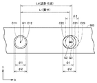
- FIG. 4 is a diagram for describing a part of the dimensions used to calculate the position of the cutting edge 139. As shown in FIG. The following description will be divided into a part using actual size data and a part using design data. Further, the actual size data will be described by being divided into measurement data acquired via the server device 400 and processed data acquired via the server device 500. The following is an example, and the present invention is not limited to this.
- the main controller 150 determines the distance L11 between the positions P11 and P14, the distance L12 between the positions P11 and P12, and the positions P13 and P14.
- the dimension based on processing data is used for the distance L13.
- the position P11 is the position of the hole into which the foot pin 141 for attaching the boom 110 to the work vehicle body is inserted. Further, the reflector is attached to the foot pin 141 as described above. Therefore, the position P11 is also the position of the reflector attached to the foot pin 141.
- the position P12 is a position where a pin for fixing the rod portion of the boom cylinder 111 to the boom 110 is inserted.
- the position P13 is a position where a pin for fixing the bottom portion of the arm cylinder 121 to the boom 110 is inserted.
- the position P14 is a position where a pin for connecting the arm 120 to the boom 110 is inserted.
- Main controller 150 sets a distance L21 between position P21 and position P22, a distance L22 between position P21 and position P25, a distance L23 between position P23 and position P24, and a distance between position P24 and position P25.
- L24 use dimensions based on processing data.
- the position P21 is a position where a pin for connecting the arm 120 to the boom 110 is inserted.
- the position P22 is a position where a pin for fixing the rod portion of the arm cylinder 121 to the arm 120 is inserted.
- the position P23 is a position where a pin for fixing the bottom portion of the bucket cylinder 131 to the arm 120 is inserted.
- the position P24 is a position where a pin for fixing one end of the link mechanism 136 of the bucket 130 to the arm 120 is inserted. The other end of the link mechanism 136 is connected to the tip of the rod portion of the bucket cylinder 131 by a pin.
- the position P25 is a position where the bucket pin 142 for connecting the arm 120 to the bucket 130 is inserted.
- the dimensions L11, L12, L13, L21, L22, L23, L24 are calculated based on the processing data instead of the design data (the actual size Data) is used.
- the main controller 150 uses dimensions based on measurement data for the distance L01 between the position P11 and the position P42 and the distance L31 between the position P32 and the position P35 at the time of calibration.
- the position P42 is the position of the reflector attached to the predetermined position of the receiving antenna 109.
- the position P32 is the position of the reflector attached to the bucket pin 142.
- the position P35 is the position of the reflector attached to the predetermined position of the cutting edge 139 of the bucket 130.
- a reflector may be attached to the contour point of the bucket 130.
- the reason for using the dimensions based on the measurement data for the distance L01 and the distance L31 is as follows.
- the bucket 130 is replaced by another type of bucket 130 having a different distance L31 by the user according to the work content.
- the cutting edge 139 is attached to the end of the bucket body by welding or bolts after the bucket body is completed by machining. For this reason, if a dimension based on processing data is used as the distance L31, the position of the cutting edge 139 can not be calculated accurately.
- the position of the cutting edge 139 can be calculated more accurately by using the measurement data rather than using the processing data.
- the main controller 150 performs calibration at a distance L02 between the position P11 and the position P41, a distance L32 between the position P32 and the position P33, and a position P33. Default data are used for the distance L33 between the position P34 and the position P34 and the distance L34 between the position P32 and the position P34.
- the position P41 is a position where a pin for connecting the bottom portion of the boom cylinder 111 to the work vehicle main body is inserted.
- the position P32 is a position where a pin for connecting the bucket 130 to the arm 120 is inserted.
- the position P33 is a position where a pin for fixing one end of the link mechanism 136 of the bucket 130 and one end of the link mechanism 137 to the rod portion of the bucket cylinder 131 is inserted.
- the position P34 is a position where a pin for fixing the other end of the link mechanism 137 to the bottom of the bucket 130 is inserted.
- ⁇ Server device 200> (1) Outline of Processing
- the server device 200 calculates distances L11, L12, L13, L21, L22, L23, L24 (see FIG. 4) using processing data (coordinate data).
- the server device 200 also calculates distances L01 and L31 (see FIG. 4) using image data (coordinate data).
- the server device 200 manages the calculated distances (actual size) using the following data table D5 and data table D6 stored in the server device 200.
- the distance L01 is a dimension used for calculation of the position of the blade tip 139, in the following, the term "dimension L01" is also described.
- the same notation as L01 is also applied to the other distances L11, L12, L13, L21, L22, L23, L24 and L31.
- FIG. 5 is a diagram showing a schematic configuration of the data table D5.
- control numbers for nine dimensions are associated with each of the machine numbers of the plurality of work vehicles.
- the management number "No. 10001" for the dimension L01, the management number “No. 20001” for the dimension L02, the management number “No. 30001” for the dimension L03, etc. are associated with the machine number "A102001” ing.
- the management number "No. 10002" for the dimension L01, the management number “No. 20002” for the dimension L02, the management number "No. 30002” for the dimension L03, etc. are associated with the machine number "A102002” ing.
- each data (machine number and management number for each dimension) in the data table D5 is input, for example, by the manufacturer of the work vehicle or the like.
- the server device 200 can know each management number of nine dimensions associated with the designated machine number by using the data table D5.
- A102001 is taken as the machine number of the work vehicle 100 as an example. Further, “A102002” and “A102003” are respectively the machine number of the work vehicle 100A and the machine number of the work vehicle 100B. The machine number "A102001” is an example of the "identification information" in the present invention.
- FIG. 6 is a diagram showing a schematic configuration of the data table D6.
- the data table D6 includes a plurality of data tables D61, D62, D63, D64, D65, D66, D67, D68, D69.
- the dimensions (the actual size of the distance L01) based on the measurement data are associated with the respective management numbers for the dimension L01. Further, in the data table D62, the dimensions (actual dimensions of the distance L11) calculated based on the coordinate data are associated with respective management numbers for the dimension L11. In the data table D63, the dimensions (actual dimensions of the distance L11) calculated based on the coordinate data are associated with respective management numbers for the dimension L12.
- a dimension calculated based on coordinate data is associated with each management number for the corresponding dimension.
- a dimension based on the measurement data is associated with each management number for the dimension L31.
- server apparatus 200 uses data table D5 and data table D6 to measure the dimensions associated with each of the nine management numbers associated with the designated machine number. You can get
- the server apparatus 200 refers to the data table D5 and selects nine management numbers "No” from a plurality of management numbers included in the data table D5. Obtain “10001”, “No. 20001”, “No. 310001”, ..., "No. 90001".
- the server apparatus 200 refers to the data table D6 (see FIG. 6), and associates the management number with each of the acquired management numbers from a plurality of dimensions included in the data table D6. Get the nine dimensions that were
- the designation of the machine number is made from each of the plurality of work vehicles.
- the machine number is sent from, for example, each work vehicle 100, 100A, 100B to the server device 200.
- the server apparatus 200 transmits the nine dimensions acquired from the data table D6 to the work vehicle that has transmitted the machine number.
- the server device 200 transmits the acquired nine dimensions to the work vehicle, with the dimensions associated with each other in the work vehicle, which are mutually identifiable.
- server apparatus 200 associates each acquired dimension with the dimension name (for example, “L01”) of the dimension and transmits it to the work vehicle.
- the working vehicle that has received nine dimensions has the actual size data (distances L11, L12, L13, and so on) of the vehicle used for calibration of a plurality of design data (19 dimensions in FIG. 10) used to calculate the blade position.
- L21, L22, L23, L24, L01, L31) can be obtained (see FIGS. 9 and 10).
- the data structure of the data table D6 shown in FIG. 6 is an example, and the present invention is not limited to this. For each of the dimensions L01, L11,.
- the server device 200 when each work vehicle 100, 100A, 100B performs calibration of a plurality of design data using measured data of the cylinder length, the server device 200 also applies to each work vehicle 100, 100A, 100B, Measured data will also be acquired as actual size data.
- the data table D5 the machine number and the control number for the dimension regarding the cylinder length may be associated, and in the data table D6, the control number and the actual measurement data may be associated.
- Each value (for example, “*** 4.2”) shown in FIG. 6 is an example of “basic data” in the present invention.
- FIG. 7 is a functional block diagram showing a functional configuration of the server device 200. As shown in FIG.
- the server device 200 includes a control unit 210, a storage unit 220, and a communication unit 230.
- the control unit 210 includes a measurement data management unit 211, a manufacturing data management unit 212, and a data acquisition unit 213.
- the measurement data management unit 211 includes an actual size calculation unit 2111.
- the manufacturing data management unit 212 includes an actual size calculation unit 2121.
- the storage unit 220 stores a data table D5 and a data table D6.
- the control unit 210 controls the overall operation of the server device 200.
- the control unit 210 is realized by a processor described later executing an operating system and a program stored in the memory.
- the communication unit 230 is an interface for communicating with the server devices 400, 500, 600 and the work vehicles 100, 100A, 100B.
- Communication unit 230 includes a receiving unit 231 that receives data, and a transmitting unit 232 that transmits data.
- the receiving unit 231 receives measurement data (coordinate data) from the server device 400 to which the camera 300 is connected.
- the receiving unit 231 receives manufacturing data from the server devices 500 and 600.
- the measurement data management unit 211 manages the measurement data received from the server device 400 based on the management number acquired from the server device 400 together with the measurement data.
- the actual size calculation unit 2111 of the measurement data management unit 211 calculates the dimensions (actual size) of the distances L01 and L31 (see FIG. 4) based on the measurement data (coordinate data). As described above, in the case of the configuration in which the server apparatus 400 calculates the dimensions, the measurement data management unit 211 does not have to include the actual size calculation unit 2111.
- the measurement data management unit 211 writes the calculated dimension in the data column of the dimension corresponding to the received management number in the data table D6. For example, when the received management number is “No. 10001”, the measurement data management unit 211 checks the No. 1 in the data table D61 (see FIG. 6) regarding the dimension L01. The calculated dimensions are written in the column of dimensions corresponding to 10001 (the column in which “*** 4.2” is entered in FIG. 6).
- the manufacturing data management unit 212 manages the processing data (coordinate data) received from the server device 500 based on the management number received from the server device 500 together with the processing data.
- the actual size calculation unit 2121 of the manufacturing data management unit 212 calculates the dimensions (actual size) of the distances L11, L12, L13, L21, L22, L23, and L24 (see FIG. 4) using the processing data (coordinate data).
- the manufacturing data management unit 212 writes the calculated dimension in the data column of the dimension corresponding to the received management number in the data table D6. For example, if the received control number is “No. 20001”, the manufacturing data management unit 212 checks the No. 1 in the data table D 62 (see FIG. 6) regarding the dimension L11. The calculated dimensions are written in the column of dimensions corresponding to 20001 (the column in which “*** 3.5” is entered in FIG. 6).
- the manufacturing data management unit 212 manages the inspection data (measured data) received from the server device 600 based on the management number received from the server device 600 together with the inspection data.
- the manufacturing data management unit 212 receives the received dimension (measured data) in the data column of the dimension corresponding to the acquired management number in the data table D6 having a configuration in which the control number for the dimension related to the cylinder length and the measured data are associated. Write the value of
- the data tables D61 to D69 shown in FIG. 6 are generated by such write processing.
- the data acquisition unit 213 acquires the machine number from the plurality of work vehicles 100, 100A, 100B via the communication unit 230. For example, when the machine number "A102001" of the work vehicle 100 is acquired, the data acquisition unit 213 refers to the data table D5 stored in the storage unit 220, and generates a plurality of management numbers in the data table D5 to "A102001". Get the control number of 9 dimensions that can be related.
- the data acquisition unit 213 refers to the data table D6 and, from the plurality of dimensions in the data table D6, the dimensions (numeric values used for calculation of the position of the cutting edge 139) associated with each of the acquired nine management numbers. Get more.
- the transmission unit 232 associates the nine dimensions acquired by the data acquisition unit 213 with the identifier of the dimensions, and transmits the nine dimensions acquired to the work vehicle 100 that is the transmission source of the machine number “A102001”.
- the work vehicle 100 uses the actual size data (distances L11, L12, L13, L21, L22, L23) of the own vehicle, which is used for calibration of a plurality of design data (19 values in FIG. 10) used to calculate the cutting edge position. , L24, L01, L31) can be obtained.
- the server device 200 transmits a plurality of data used for calculation of the position of the cutting edge 139 of the work vehicle 100 to the work vehicle 100 by receiving the machine number of the work vehicle 100.
- work vehicle 100 can acquire a plurality of data used for calculation of the position of cutting edge 139 at one time only by transmitting the machine number. Therefore, according to work machine system 1, it is possible to quickly obtain a plurality of data used for calculation of the position of cutting edge 139 of work vehicle 100.
- the control unit 210 is an example of the “control unit” in the present invention.
- the data acquisition unit 213 is an example of the “acquisition unit” in the present invention.
- the transmission unit 232 is an example of the “transmission unit” in the present invention.
- the storage unit 220 is an example of the “storage unit” in the present invention.
- FIG. 8 is a diagram showing the hardware configuration of the server device 200. As shown in FIG.
- the server device 200 includes a processor 201, a memory 202, a communication interface 203, an operation key 204, a monitor 205, and a reader / writer 206.
- the memory 202 typically includes a ROM 2021, a RAM 2022, and an HDD (Hard Disc) 2023.
- the reader / writer 206 reads various data including a program from a memory card 299 as a storage medium, and writes data in the memory card 299.
- the processor 201 corresponds to the control unit 210 in FIG. More specifically, the control unit 310 is realized by the processor 201 executing a program stored in the memory 202.
- the memory 202 corresponds to the storage unit 220 in FIG.
- the communication interface 203 corresponds to the communication unit 230 in FIG.
- the processor 201 executes a program stored in the memory 202.
- the RAM 2022 temporarily stores various programs, data generated by execution of the program by the processor 201, and data input by the user.
- the ROM 2021 is a non-volatile storage medium, and typically stores a BIOS (Basic Input Output System) and firmware.
- the HDD 2023 stores an OS (Operating System), various application programs, and the like.
- Software such as programs stored in the memory 202 may be stored in a memory card or other storage medium and distributed as a program product. Alternatively, the software may be provided as a downloadable program product by an information provider connected to the so-called Internet. Such software is temporarily stored in the RAM 2022 after being read from the storage medium by a memory card reader / writer or other reader or downloaded via an interface. The software is read from the RAM 2022 by the processor 201, and is further stored in the HDD 2023 in the form of an executable program. The processor 201 executes the program.
- Each component which comprises the server apparatus 200 shown by the figure is general. Therefore, an essential part of the present invention can be said to be software stored in the memory 202, a memory card or other storage medium, or software downloadable via a network.
- the recording medium is not limited to a DVD (Digital Versatile Disc) -ROM, a CD (Compact Disc) -ROM, an FD (Flexible Disk), and a hard disk.
- DVD Digital Versatile Disc
- CD Compact Disc
- FD Fluorescent Disk
- hard disk For example, magnetic tape, cassette tape, optical disk (MO (Magnetic Optical Disc) / MD (Mini Disc)), optical card, mask ROM, EPROM (Electronically Programmable Read-Only Memory), EEPROM (Electronically Erasable Programmable Read-Only Memory)
- the medium may be a fixedly carrying program such as a semiconductor memory such as a flash ROM.
- the recording medium is a non-transitory medium that can read the program and the like from a computer, and does not include a temporary medium such as a carrier wave.
- the program referred to here includes not only a program directly executable by the processor 201 but also a program in source program format, a compressed program, an encrypted program and the like.
- server devices 400, 500, and 600 have the same hardware configuration as server device 200, description of the hardware configuration of server devices 400, 500, and 600 will not be repeated here.
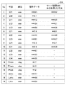
- FIG. 9 is a diagram showing an outline of the data D9 stored in the work vehicle 100. As shown in FIG.
- design data and a dimension acquired by the work vehicle 100 from the server device 200 are stored in association with each other.
- design data No. 1 to No. Up to 19 19 values are stored.
- the design data includes, in addition to the design dimensions, a design angle for the boom 110, a design angle for the arm 120, a design angle for the bucket 130 and the like.
- the dimensions acquired by the work vehicle 100 from the server device 200 include dimensions (actual dimensions) based on processing data and dimensions (actual dimensions) based on image data (measurement data).
- the dimensions acquired from server apparatus 200 No. 1 3 to No.
- the dimensions up to 9 are dimensions based on processing data.
- the size of 10 is a size based on image data.
- FIG. 10 is data D10 for explaining the calibration process and the value after calibration. As illustrated in FIG. 10, the main controller 150 obtains the actual size of the distances L01, L11, L12, L13, L21, L22, L22, L24, and L31 from the server device 200.
- the main controller 150 uses the actual dimensions for the distances L01, L11, L12, L13, L21, L22, L23, L24, L31 at the time of calibration. Further, the main controller 150 uses design data for other values (distances L02, L32, L33, L34, Lbms, Lams, Lbks, angles Phibm, Phiam, Phibk).
- the distances Lbms, Lams, and Lbks are values regarding the boom cylinder 111, the arm cylinder 121, and the bucket cylinder 131, respectively.
- the angles Phibm, Phiam, and Phibk are values for the boom 110, the arm 120, and the bucket 130, respectively.
- the main controller 150 uses these 19 values (actual size data and design data) to calibrate 19 design data (default values). Thereby, the main controller 150 obtains a value after calibration.
- the calculation method of the calibration is the same as when using a conventional surveying instrument such as a total station, and therefore will not be described here.
- FIG. 11 is a diagram showing a hardware configuration of the work vehicle 100. As shown in FIG.
- the work vehicle 100 includes a cylinder 37, an operating device 51, a communication IF (Interface) 52, a monitoring device 53, an engine controller 54, an engine 55, a main pump 56A, and a pilot.
- Pump 56B swash plate drive device 57, pilot oil passage 58, electromagnetic proportional control valve 59, main valve 60, pressure sensor 62, tank 63, hydraulic oil passage 64, receiving antenna 109 And a main controller 150.
- the cylinder 37 represents and represents any one of the boom cylinder 111, the arm cylinder 121, and the bucket cylinder 131.
- the cylinder 37 drives one of the boom 110, the arm 120 and the bucket 130.
- the operating device 51 includes an operating lever 511 and an operation detector 512 that detects the amount of operation of the operating lever 511.
- the main valve 60 has a spool 60A and a pilot chamber 60B.
- the operating device 51 is a device for operating the work implement 104.
- the operating device 51 is a hydraulic device. Oil is supplied to the controller 51 from the pilot pump 56B.
- the pressure sensor 62 detects the pressure of the oil discharged from the operating device 51.
- the pressure sensor 62 outputs the detection result to the main controller 150 as an electrical signal.
- the engine 55 has a drive shaft for connecting to the main pump 56A and the pilot pump 56B.
- the rotation of the engine 55 discharges hydraulic oil from the main pump 56A and the pilot pump 56B.
- the engine controller 54 controls the operation of the engine 55 in accordance with an instruction from the main controller 150.
- the main pump 56 ⁇ / b> A supplies the hydraulic oil used to drive the work implement 104 through the hydraulic oil passage 64.
- a swash plate drive device 57 is connected to the main pump 56A.
- the pilot pump 56 B supplies hydraulic oil to the electromagnetic proportional control valve 59 and the operating device 51.
- the swash plate drive device 57 is driven based on an instruction from the main controller 150 to change the inclination angle of the swash plate of the main pump 56A.
- the monitor device 53 is communicably connected to the main controller 150.
- the monitor device 53 notifies the main controller 150 of an input instruction by the operator.
- the monitor device 53 performs various displays based on an instruction from the main controller 150.
- the main controller 150 is a controller that controls the entire work vehicle 100, and includes a central processing unit (CPU), a non-volatile memory, a timer, and the like.
- the main controller 150 controls the engine controller 54 and the monitor device 53.
- the main controller 150 receives an electrical signal from the pressure sensor 62.
- the main controller 150 generates a command current according to the electric signal.
- the main controller 150 outputs the generated command current to the electromagnetic proportional control valve 59.
- the main controller 150 is a bucket based on various information such as position information of the vehicle obtained from the receiving antenna 109 for GNSS, stroke length of the cylinder 37, and information from an inertial sensor unit (not shown) built in the vehicle.
- the position information of the cutting edge 139 of 130 is calculated.
- the main controller 150 controls the operation of the working machine 104 (the boom 110, the arm 120, the bucket 130) so as not to damage the design surface while collating the position information with the construction design data.
- the main controller 150 automatically stops the work implement 104 or moves the cutting edge 139 along the design surface with the assist function.
- main controller 150 executes the above-described calibration process to calculate the accurate position of the cutting edge 139.
- the electromagnetic proportional control valve 59 is provided in a pilot oil passage 58 connecting the pilot pump 56B and the pilot chamber 60B of the main valve 60, and uses the hydraulic pressure supplied from the pilot pump 56B to issue a command from the main controller 150 Generate a command pilot pressure according to the current.
- the main valve 60 is provided between the electromagnetic proportional control valve 59 and the cylinder 37.
- the main valve 60 adjusts the flow rate of the hydraulic oil that operates the cylinder 37 based on the command pilot pressure generated by the electromagnetic proportional control valve 59.
- the tank 63 is a tank for storing oil used by the main pump 56A and the pilot pump 56B.
- FIG. 12 is a functional block diagram showing a functional configuration of work vehicle 100. As shown in FIG.
- the work vehicle 100 includes a main controller 150, a communication unit 160, and a monitor device 53.
- the main controller 150 has a storage unit 151, a calibration unit 152, and a blade edge position calculation unit 153.
- the monitor device 53 includes a display unit 171 and an input unit 172.
- the communication unit 160 is an interface for communicating with the server device 200.
- the communication unit 160 acquires the actual size data described above from the server device 200, and sends the actual size data to the main controller 150.
- the actual size data is stored in the storage unit 151.
- the storage unit 151 stores in advance a plurality of design data such as design dimensions and design angles.
- design data such as design dimensions and design angles.
- the 19 design data shown in FIG. 9 are stored in advance in the storage unit 151 of the main controller 150.
- the calibration unit 152 uses actual size data for the distances L01, L11, L12, L13, L21, L22, L22, L24, and L31, and other values (distances L02 and L32) are used. , L33, L34, Lbms, Lams, Lbks, angles Phibm, Phiam, Phibk), the design data itself is used to calibrate these 19 values.
- the calibration unit 152 stores, in the storage unit 151, the data after calibration obtained by the calibration.
- the cutting edge position calculation unit 153 calculates the position of the cutting edge 139 using the data after calibration.
- the display unit 171 displays various screens. For example, the display unit 171 displays various guidances of the calibration process.
- the input unit 172 receives various input operations. In one aspect, the input unit 172 receives an instruction to execute the calibration process.
- the main controller 150 When the input unit 172 receives an execution instruction of the calibration process, the main controller 150 performs control to transmit the machine number of the work vehicle 100 to the server device 200 via the communication unit 160.
- the machine number is stored in advance in the storage unit 151.
- FIG. 13 is a sequence diagram for explaining the flow of processing in the work machine system 1.
- sequence S ⁇ b> 1 the camera 300 sends image data obtained by imaging of the work vehicle 100 to the server device 400.
- the server device 400 performs predetermined image processing on the received image data to calculate three-dimensional coordinate data (measurement data) between the reflectors.
- the server device 400 calculates three-dimensional coordinate data of the reflector for each of the plurality of work vehicles 100.
- the server device 200 requests the server device 400 to transmit measurement data.
- the server device 400 transmits measurement data to the server device 200.
- the server device 200 requests the server device 500 to transmit measurement data.
- the server device 500 transmits the processing data to the server device 200.
- the server device 200 requests the server device 600 to transmit measurement data.
- the server device 600 transmits the inspection data to the server device 200.
- server device 200 calculates the actual size of distances L01, L11, L12, L13, L21, L22, L23, L24, L31 based on the received measurement data, processing data, and inspection data (FIG. 4, Figure 9).
- server apparatus 200 determines the distances L01, L11, L12, L13, L21, L22, L22, L23, L24, based on the received measurement data and processing data. Calculate the actual size of L31.
- sequence S10 the server device 200 updates the data table D6 (FIG. 6) using the calculated actual size.
- sequence S11 the work vehicle 100 requests the server apparatus 200 to transmit the actual size data of the vehicle used for calibration. In the case of this example, the work vehicle 100 transmits a request signal including the machine number of the work vehicle 100 to the server device 200.
- sequence S ⁇ b> 12 the control unit 210 of the server device 200 executes a process of acquiring from the storage unit 220 data concerning the work vehicle of the transmission request source.
- the server device 200 transmits the actual size data of the transmission request source to the work vehicle 100 of the transmission request source.
- sequence S14 the work vehicle 100 performs a calibration process using the acquired actual size data.
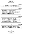
- FIG. 14 is a flowchart for explaining the details of the process of sequence S12 in FIG.
- step S ⁇ b> 121 the server device 200 receives a machine number from a work vehicle.
- server apparatus 200 receives machine number “A102001” from work vehicle 100.
- step S122 the server device 200 acquires a plurality of management numbers associated with the received machine number in the data table D5 stored in the storage unit 220. For example, the server device 200 acquires nine management numbers "No. 10001", “No. 20001", “No. 30001”, ..., "No. 90001".
- step S123 the server device 200 acquires, in the data table D6 (data tables D61 to D69) stored in the storage unit 220, the dimensions associated with each of the plurality of management numbers acquired in step S122.
- step S124 the server apparatus 200 transmits the nine dimensions acquired in step S123 to the work vehicle that is the transmission source of the machine number. For example, the server apparatus 200 transmits nine dimensions to the work vehicle 100 that is the transmission source of the management number “A102001”.
- the server device 200 of the work machine system 1 has the following configuration. Moreover, the following effects are achieved by the configuration.
- the work vehicle 100 transmits the machine number associated with the work vehicle 100 to the server device 200.
- the server device 200 acquires, based on the machine number, a data acquisition unit 213 that acquires data (hereinafter, also referred to as “basic data”) used to calculate the position of the cutting edge 139 of the bucket 130.
- a transmission unit 232 for transmitting the information.
- the work vehicle 100 transmits the machine number of the work vehicle 100 to the server device 200, whereby data (basic data) used for calculation of the position of the cutting edge 139 of the work vehicle 100 is obtained. It becomes possible to acquire from the server apparatus 200.
- work vehicle 100 can acquire data used for calculation of the position of cutting edge 139 only by transmitting the machine number. Therefore, according to the work machine system 1, it is possible to quickly obtain data used for calculating the position of the cutting edge 139 of the work vehicle 100.
- the work vehicle 100 acquires the said several data, it performs the calibration process mentioned above using the said data.
- the server device 200 further includes a storage unit 220 that stores, as the basic data, each of the first basic data and the second basic data in association with the machine number.
- the data acquisition unit 213 acquires the first basic data and the second basic data from the storage unit 220 based on the machine number.
- the work vehicle 100 transmits two machine numbers of the work vehicle 100 to the server device 200 to thereby transmit two basic data used for calculation of the position of the cutting edge 139 of the work vehicle 100. It becomes possible to obtain from the device 200 at one time.
- the storage unit 220 stores, as the first basic data, the first dimension obtained based on the manufacturing data of the first component included in the work machine 104 in association with the machine number, As second basic data, a second dimension obtained based on manufacturing data of a second component included in the work machine 104 is stored in association with a machine number.
- the work vehicle 100 transmits two machine numbers of the work vehicle 100 to the server device 200 to thereby calculate two dimensions used for calculation of the position of the cutting edge 139 of the work vehicle 100. It becomes possible to acquire from 200 at once.
- the basic data is a dimension obtained based on manufacturing data of the components included in the work machine 104. According to such a configuration, the dimensions obtained based on the manufacturing data of the component can be used for the calibration process in the work vehicle 100.
- the manufacturing data is, for example, machining data when machining the boom 110. According to such a configuration, machining data at the time of machining of the boom 110 can be used for calibration processing in the work vehicle 100.
- the manufacturing data is, for example, machining data at the time of machining of the arm 120. According to such a configuration, machining data at the time of machining of the arm 120 can be used for calibration processing in the work vehicle 100.
- the basic data is the dimension between the cutting edge 139 of the work vehicle 100 and the bucket pin 142 (see FIG. 4). According to such a configuration, the dimension (measurement data) between the cutting edge 139 of the work vehicle 100 and the bucket pin 142 can be used for the calibration process in the work vehicle 100.
- the basic data is a dimension representing the dimension between the receiving antenna 109 and the foot pin 141 for the global positioning satellite system. According to such a configuration, it is possible to use the dimension (measurement data) between the receiving antenna 109 and the foot pin 141 for the calibration process in the work vehicle 100.
- the work vehicle 100 stores the machine number of the work vehicle 100 in advance, and transmits the machine number to the server device 200 when it receives an instruction to execute the calibration process. According to such a configuration, the operator of the work vehicle 100 can transmit the machine number of the work vehicle 100 to the server device 200 only by instructing the work vehicle 100 to execute the calibration process.
- the main controller 150 is used to calculate the position of the cutting edge 139 using the dimensions obtained based on the manufacturing data of the components included in the work machine 104.
- the design data is calibrated, and the position of the cutting edge 139 is calculated using the calibrated design data.
- such a configuration will be described.
- the main controller 150 acquires design data used to calculate the position of the cutting edge 139 based on the dimensions obtained from the manufacturing data, and uses the design data to determine the position of the cutting edge 139. calculate. Further, the main controller 150 acquires design data used to calculate the position of the cutting edge 139 based on the dimensions obtained from the image data, and calculates the position of the cutting edge 139 using the design data.
- FIG. No. 3 uses dimensions based on processing data as design data of dimensions 3 to 9 and The dimensions based on image data are used as design data of dimensions 1 and 10. For example, No. For the dimension of 3, instead of "***. 12" as design data, "***. 35" which is a dimension based on processing data is used.
- the main controller 150 calculates the position of the cutting edge 139 using design data of 19 values (dimensions and angles) including the actual size based on the processing data and the actual size based on the image data. More specifically, main controller 150 calibrates, for example, ten values in the column of design data and nine values in the column of dimensions acquired from server device 200 in data D10 shown in FIG. 10, for example. Instead, they are substituted into variables in a program for calculating the position of the cutting edge 139. Thus, the main controller 150 calculates the position of the cutting edge 139.
- the main controller 150 does not need to perform the calibration process. Therefore, according to the present modification, it is possible to obtain design data used for calculation of the position of the cutting edge 139 more quickly than in the configuration in which the calibration process is performed.
- the unique identification number is not limited to the machine number. It is sufficient that the machine number can be uniquely identified by the unique identification number.
- the configuration has been described by way of example in which the work vehicle 100 transmits the request signal including the machine number.
- the transmission source of the machine number may be a tablet terminal instead of the work vehicle.
- the work machine system 1 may be configured such that the dimensions acquired in the server device 200 are transmitted to the work vehicle having the machine number instead of the machine number transmission source.
- the dimensions acquired by the server device 200 may be transmitted to the tablet terminal of the transmission source of the machine number.
- the operator refers to the actual size data displayed on the tablet terminal and manually stores these data in the storage unit 151 of the main controller 150 via the monitor device 53.
- the device of the transmission source of the machine number and the device of receiving the dimension data may or may not be the same.
- the server apparatus 200 may store, instead of the data table D5 and the data table D6, a data table in which the dimension (numerical value) indicated in the data table D6 is described in the management number column of the data table D5. .
- the server device 200 can transmit nine dimensions to the work vehicle 100 only by referring to one data table.
- Reference Signs List 1 working machine system 37 cylinder, 51 operation device, 53 monitor device, 54 engine controller, 55 engine, 56A main pump, 56B pilot pump, 57 swash plate drive device, 58 pilot oil passage, 59 electromagnetic proportional control valve, 60 Main valve, 60A spool, 60B pilot room, 62 pressure sensor, 63 tank, 64 hydraulic oil path, 100, 100A, 100B working vehicle, 101 traveling body, 103 revolving unit, 104 working machine, 107 handrail, 108 cab , 109 receiving antenna, 110 boom, 111 boom cylinder, 120 arm, 121 arm cylinder, 130 bucket, 131 bucket cylinder, 136, 137 link mechanism, 139 cutting edge, 141 f Topin 142 bucket pin 150 main controller 151, 220 memory unit 152 calibration unit 153 blade edge position calculation unit 160 230 communication unit 171 display unit 172 input unit 200 400 500 600 server apparatus 201 processor, 202 memory, 203 communication interface, 204 operation key, 205 monitor, 210, 310 control unit, 211
Landscapes
- Engineering & Computer Science (AREA)
- Mining & Mineral Resources (AREA)
- Civil Engineering (AREA)
- General Engineering & Computer Science (AREA)
- Structural Engineering (AREA)
- Mechanical Engineering (AREA)
- Operation Control Of Excavators (AREA)
Abstract
システムは、バケットを含む作業機を有する作業機械と、作業機械と通信可能なサーバとを備える。作業機械は、当該作業機械に関連付けられた識別番号をサーバに送信する。サーバは、識別情報に基づき、バケットの刃先位置の算出に用いられる基礎データを取得する。サーバは、取得された基礎データを作業機械に対して送信する。
Description
本発明は、作業機械システムおよび制御方法に関する。
従来、シリンダの長さに基づきバケットの刃先位置を算出する建設機械が知られている。このような建設機械では、刃先位置を正確に算出するため、刃先位置の算出に用いる設計データを事前に較正する必要がある。この較正には、建設機械における所定の位置同士の間の実寸データが用いられる。この実寸データは、建設機械の生産ラインで測量機器を用いて取得される。
上記のように測量機器を用いて実寸データを得るためには、複数の人手と、ある程度の作業時間とが必要になる。
本発明の目的は、刃先位置の算出に用いるデータの取得を迅速に行うことが可能な作業機械システムおよび制御方法を提供することにある。
本発明のある局面に従うと、作業機械システムは、バケットを含む作業機を有する作業機械と、作業機械と通信可能なサーバとを備える。作業機械は、当該作業機械に関連付けられた識別番号をサーバに送信する。サーバは、識別情報に基づき、バケットの刃先位置の算出に用いられる基礎データを取得する取得部と、取得された基礎データを作業機械に対して送信する送信部とを有する。
本発明によれば、刃先位置の算出に用いるデータの取得を迅速に行うことが可能となる。
以下、実施形態について図に基づいて説明する。以下の説明では、同一部品には、同一の符号を付している。それらの名称および機能も同じである。したがって、それらについての詳細な説明は繰り返さない。また、実施形態における構成を適宜組み合わせて用いることは当初から予定されていることである。また、一部の構成要素を用いない場合もある。
以下、サーバ装置と作業機械とを有する作業機械システムについて、図面を参照しながら説明する。また、当該作業機械の一例としての作業車両について、以下説明する。さらに、以下においては、作業車両として、油圧ショベルを例に挙げて説明する。特に、ICT(Information and Communication Technology)油圧ショベルを例に挙げて説明する。
なお、以下の説明において、「上」,「下」,「前」,「後」,「左」,「右」とは、作業車両の運転席に着座したオペレータを基準とする用語である。
<処理の概要>
本実施の形態では、サーバ装置は、作業車両から機体番号を受信する。サーバ装置は、当該機体番号に基づいて、サーバ装置に記憶されたデータテーブルから、当該作業車両がバケットの刃先位置の算出に用いる複数のデータを取得する。サーバ装置は、取得した複数のデータを作業車両に対して送信する。以下では、このような処理を含む各種の処理の具体的内容について、図面を参照して説明する。
本実施の形態では、サーバ装置は、作業車両から機体番号を受信する。サーバ装置は、当該機体番号に基づいて、サーバ装置に記憶されたデータテーブルから、当該作業車両がバケットの刃先位置の算出に用いる複数のデータを取得する。サーバ装置は、取得した複数のデータを作業車両に対して送信する。以下では、このような処理を含む各種の処理の具体的内容について、図面を参照して説明する。
<全体構成>
図1は、実施形態に基づく作業機械システムの概略構成を表した図である。
図1は、実施形態に基づく作業機械システムの概略構成を表した図である。
図1に示されるように、作業機械システム1は、複数の作業車両100,100A,100Bと、複数のサーバ装置200,400,500,600と、カメラ300と、送受信機800とを備えている。なお、作業車両の数は、3台に限定されるものではない。
カメラ300と、サーバ装置400とは通信可能に接続されている。サーバ装置200と、サーバ装置400,500,600とは通信可能に接続されている。サーバ装置200は、インターネット等のネットワーク700を介して、送受信機800と通信可能に接続されている。
なお、サーバ装置200が、本発明における「サーバ」の例である。作業車両100が、本発明における「作業機械」の例である。
(1)作業車両100の全体構成
図1に示されるように、作業車両100は、走行体101と、旋回体103と、作業機104と、全球測位衛星システム(GNSS)用の受信アンテナ109とを主に有している。作業車両本体は、走行体101と旋回体103とにより構成される。走行体101は、左右1対の履帯を有している。旋回体103は、走行体101の上部の旋回機構を介して旋回可能に装着される。
図1に示されるように、作業車両100は、走行体101と、旋回体103と、作業機104と、全球測位衛星システム(GNSS)用の受信アンテナ109とを主に有している。作業車両本体は、走行体101と旋回体103とにより構成される。走行体101は、左右1対の履帯を有している。旋回体103は、走行体101の上部の旋回機構を介して旋回可能に装着される。
作業機104は、旋回体103において、上下方向に作動可能に軸支されており、土砂の掘削などの作業を行う。作業機104は、構成部品として、ブーム110と、アーム120と、バケット130と、ブーム用シリンダ111と、アーム用シリンダ121と、バケット用シリンダ131とを含む。
ブーム110の基部は、旋回体103に可動可能に連結されている。アーム120は、ブーム110の先端に可動可能に連結されている。バケット130は、アーム120の先端に可動可能に連結されている。旋回体103は、運転室108と、手すり107とを含む。本例では、受信アンテナ109は、手すり107に取り付けられている。
ブーム110は、ブーム用シリンダ111により駆動する。アーム120は、アーム用シリンダ121により駆動する。バケット130は、バケット用シリンダ131により駆動する。
なお、作業車両100の作業機104は、本発明における「作業機」の例である。作業車両100のバケット130は、本発明の「バケット」の例である。
作業車両100A,100Bは、作業車両100と同様の構成を有するため、作業車両100A,100Bの構成については繰り返し説明しない。以下では、主として、複数の作業車両100,100A,100Bのうちの作業車両100に着目して説明する。
(2)三次元測定
カメラ300は、3次元測定用のカメラである。カメラ300は、デュアルカメラセンサを有する。カメラ300は、複数の所定の位置にリフレクタが取り付けられた作業車両100を事前に撮像し、当該撮像により得られた画像データをサーバ装置400に送る。本例では、リフレクタは、受信アンテナ109、バケット130の刃先、フートピン141、バケットピン142に取り付けられる。
カメラ300は、3次元測定用のカメラである。カメラ300は、デュアルカメラセンサを有する。カメラ300は、複数の所定の位置にリフレクタが取り付けられた作業車両100を事前に撮像し、当該撮像により得られた画像データをサーバ装置400に送る。本例では、リフレクタは、受信アンテナ109、バケット130の刃先、フートピン141、バケットピン142に取り付けられる。
サーバ装置400は、3次元データ(3Dデータ)を取得するためのソフトウェアが予めインストールされている。サーバ装置400は、カメラ300から送られてきた3次元の画像データに基づき、リフレクタの3次元の座標データ(以下、「測定データ」とも称する)を算出する。このように、測定データは、画像データにより得られる。
サーバ装置400は、複数の作業車両100の各々について、リフレクタの3次元の座標データを算出する。サーバ装置400は、作業車両の機体番号に関連付けられた管理番号と、座標データとを関連付けて記憶する。サーバ装置400は、サーバ装置200からの要求に応じて、座標データを管理番号に関連付けて、サーバ装置200に送信する。なお、管理番号は、識別番号であって、その具体例については、後述する(図5、図6)。
なお、本実施形態の例では、サーバ装置200が、測定データから実寸データを算出する構成を例に挙げて説明するが、これに限定されるものではない。サーバ装置200の代わりにサーバ装置400が、測定データから実寸データを算出するようにしてもよい。この場合には、サーバ装置400は、測定データの代わりに、実寸データをサーバ装置200に送信すればよい。
(3)製造データ
サーバ装置500,600は、作業機104に含まれる構成部品の製造データを、作業車両の機体番号に関連付けられた管理番号に関連付けて記憶している。製造データは、機械加工時の実際の機械加工データ(以下、「加工データ」とも称する)と、製品の検査により得られた検査データとを含む。
サーバ装置500,600は、作業機104に含まれる構成部品の製造データを、作業車両の機体番号に関連付けられた管理番号に関連付けて記憶している。製造データは、機械加工時の実際の機械加工データ(以下、「加工データ」とも称する)と、製品の検査により得られた検査データとを含む。
加工データは、機械加工時の実際の加工位置を表すデータであって、設計データとは異なる。機械加工は、典型的には、図示しない工作機械によって行われる。
サーバ装置500は、ブーム110、アーム120等の作業機104に含まれる構成部品の加工データを、管理番号に関連付けて記憶している。サーバ装置500は、たとえば、上記の加工データとして、ピン穴の位置(座標データ)を記憶している。
サーバ装置500は、サーバ装置200からの要求に応じて、加工データとしての座標データを管理番号に関連付けて、サーバ装置200に送信する。
サーバ装置600は、ブーム用シリンダ111、アーム用シリンダ121、バケット用シリンダ131等の作業機104に含まれる構成部品の検査データを、これらのシリンダが取り付けられる予定の作業車両100の機体番号に関連付けられた管理番号に関連付けて記憶している。サーバ装置600は、上記検査データとして、実測データを記憶している。
サーバ装置600は、たとえば、上記の実測データとして、これらのシリンダが最も伸びたときのシリンダ長と、シリンダが最も縮んだときのシリンダ長とを記憶している。
サーバ装置600は、サーバ装置200からの要求に応じて、検査データとしての実測データを管理番号に関連付けて、サーバ装置200に送信する。
(4)実寸データの生成
サーバ装置200は、サーバ装置400から取得した測定データ(座標データ)と、サーバ装置500から取得した加工データ(座標データ)と、サーバ装置600から取得した検査データ(実測データ)とを、作業車両100の機体番号に関連付けられた管理番号に関連付けて管理する。このような処理によって、サーバ装置200では、複数の作業車両100のデータが個別に管理されることになる。サーバ装置200によるデータの管理方法の詳細については、後述する(図5,図6)。
サーバ装置200は、サーバ装置400から取得した測定データ(座標データ)と、サーバ装置500から取得した加工データ(座標データ)と、サーバ装置600から取得した検査データ(実測データ)とを、作業車両100の機体番号に関連付けられた管理番号に関連付けて管理する。このような処理によって、サーバ装置200では、複数の作業車両100のデータが個別に管理されることになる。サーバ装置200によるデータの管理方法の詳細については、後述する(図5,図6)。
サーバ装置200は、測定データから実寸データを算出する。また、サーバ装置200は、加工データから実寸データを算出する。詳細については後述するが、サーバ装置200は、座標データに基づき、2つの座標同士の間の長さ(実寸データ)を算出する。
サーバ装置200は、作業車両100からの要求に応じて、当該要求を行った作業車両100に対して、当該要求を行った作業車両100の実寸データを、較正用のデータとして送信する。
(5)較正処理の概要
作業車両100は、サーバ装置200から、自車両の較正用のデータを取得する。作業車両100は、この較正用データを利用して、刃先位置の算出に用いる設計データを較正する。詳しくは、作業車両100は、寸法を表した較正用データを利用して、刃先の位置の算出に用いる複数のデフォルト値(設計寸法、設計角度)を変更する。なお、較正処理の詳細については、後述する。
作業車両100は、サーバ装置200から、自車両の較正用のデータを取得する。作業車両100は、この較正用データを利用して、刃先位置の算出に用いる設計データを較正する。詳しくは、作業車両100は、寸法を表した較正用データを利用して、刃先の位置の算出に用いる複数のデフォルト値(設計寸法、設計角度)を変更する。なお、較正処理の詳細については、後述する。
<設計データおよび加工データ>
較正処理の詳細を説明する前に、作業車両100に含まれる所定の構成部品の設計データと加工データとについて説明する。
較正処理の詳細を説明する前に、作業車両100に含まれる所定の構成部品の設計データと加工データとについて説明する。
図2は、サーバ装置500に格納されている設計データと加工データとの一例を説明するための図である。
図2に示されるように、データD2では、ブーム110およびアーム120の各々のピン穴に対して、設計データと、加工データとが関連付けて記憶されている。また、サーバ装置500は、このようなデータD2を作業車両100の機体番号に関連付けられた管理番号に関連付けて、作業車両毎に記憶している。データD2の例では、設計データおよび加工データは、ピン穴の中心位置を表している。本例では、この中心位置を表した設計データ自体が較正されるのではなく、2つの中心位置同士の間の寸法(設計データ)が較正される。
なお、設計データは、同種の作業車両で同一であるため、図2に示されるように加工データに直接的に関連付けられていなくてもよい。
図3は、設計データと加工データとのずれが生じる理由を説明するための図である。
図3に示されるように、鋳物900に直径φ2の2つの穴C12,C22が形成される場合を例に挙げて説明する。なお、鋳物900は、ブーム110、アーム120に対応する。
図3に示されるように、鋳物900に直径φ2の2つの穴C12,C22が形成される場合を例に挙げて説明する。なお、鋳物900は、ブーム110、アーム120に対応する。
鋳物900には、工作機械で直径φ2の2つの穴C12,C22が形成される前に(鋳物が完成した時点で)、直径φ1の2つの下穴C11,C21が既に形成されている。
下穴C11,C21に基づいて形成されるべき2つの穴の設計データの中心位置Q1,Q3の座標値が、それぞれ、(Xa,Ya)、(Xc,Yc)であったとする。また、下穴C11の中心位置Q1の座標(Xa,Ya)であり、下穴C21の中心位置が設計データの中心位置Q3からずれていたとする。
この場合、工作機械は、下穴C11の中心位置が設計データの中心位置と一致しているため、穴C12の中心位置を、下穴C11の中心位置Q1と一致させることができる。しかしながら、下穴C21の中心位置と、設計データの中心位置Q3とは一致していないため、φ1とφ2との関係次第では、工作機械は、Q3(Xc,Yc)を中心とした直径φ2の穴(円形の穴)を形成できない。それゆえ、工作機械は、中心位置がQ2(Xb,Yb)となる直径φ2の穴を形成する。なお、中心位置Q2は、直径φ2の穴を形成することができ、かつ、設計データの中心位置Q3からの距離が最短となる位置である。
このように、設計データの中心位置Q3と加工データの中心位置Q2とは異なる位置となる。したがって、設計データと加工データとのずれが生じる。
なお、このような穴の位置を設計データから変更する処理は、工作機械におけるNCプログラムによって予め規定されている。また、工作機械が加工データを記憶しており、当該加工データは、サーバ装置500等に送信される。
<較正処理の詳細>
作業車両100のメインコントローラ150(図11参照)は、上述したように、複数の寸法を表した較正用データ(実寸データ)を利用して、刃先139の位置を算出するために用いられる複数の設計データを較正する。なお、設計データとしては、寸法(長さ)と角度とがある。
作業車両100のメインコントローラ150(図11参照)は、上述したように、複数の寸法を表した較正用データ(実寸データ)を利用して、刃先139の位置を算出するために用いられる複数の設計データを較正する。なお、設計データとしては、寸法(長さ)と角度とがある。
メインコントローラ150は、サーバ装置200から送信された実寸データと、既知の設計データ(複数の設計データの一部)とを用いて較正を行う。一例として、刃先139の位置の算出に19個の値(寸法および角度)が必要であるとする。メインコントローラ150は、19個の値の一部については、設計データの代わりにサーバ装置200から取得した実寸データを利用し、かつ残りについては設計データ自体を利用して、19個の値(設計データ)の較正を行う。なお、これらの処理の具体例については、図9および図10に基づいて説明する。
以下では、説明の便宜上、サーバ装置600から取得した検査データ(シリンダ長の実測データ)を利用せずに、複数の設計データの較正を行う場合を例に挙げて説明する。なお、サーバ装置600から取得した検査データを利用することも当然に可能である。
図4は、刃先139の位置の算出に用いる寸法の一部を説明するための図である。以下では、実寸データを利用する箇所と、設計データを利用する箇所とに分けて説明する。さらに、実寸データについては、サーバ装置400を介して取得した測定データと、サーバ装置500を介して取得した加工データとに分けて説明する。なお、以下は、一例であって、これに限定されるものではない。
(1)加工データに基づく寸法(実寸データ)を利用する箇所
まず、ブーム110に関する寸法を説明する。図4に示されるように、メインコントローラ150は、較正の際に、位置P11と位置P14と間の距離L11と、位置P11と位置P12と間の距離L12と、位置P13と位置P14と間の距離L13とについて、加工データに基づく寸法を用いる。
まず、ブーム110に関する寸法を説明する。図4に示されるように、メインコントローラ150は、較正の際に、位置P11と位置P14と間の距離L11と、位置P11と位置P12と間の距離L12と、位置P13と位置P14と間の距離L13とについて、加工データに基づく寸法を用いる。
位置P11は、ブーム110を作業車両車体に取り付けるフートピン141が挿入される穴の位置である。また、フートピン141には、上述したように、リフレクタが取り付けられる。よって、位置P11は、フートピン141に取り付けられたリフレクタの位置でもある。位置P12は、ブーム用シリンダ111のロッド部をブーム110に固定するためのピンが挿入される位置である。位置P13は、アーム用シリンダ121のボトム部をブーム110に固定するためのピンが挿入される位置である。位置P14は、ブーム110にアーム120を接続するためのピンが挿入される位置である。
次に、アーム120に関する寸法を説明する。メインコントローラ150は、位置P21と位置P22と間の距離L21と、位置P21と位置P25と間の距離L22と、位置P23と位置P24と間の距離L23と、位置P24と位置P25と間の距離L24とについて、加工データに基づく寸法を用いる。
位置P21は、アーム120をブーム110に接続するためのピンが挿入される位置である。位置P22は、アーム用シリンダ121のロッド部をアーム120に固定するためのピンが挿入される位置である。位置P23は、バケット用シリンダ131のボトム部をアーム120に固定するためのピンが挿入される位置である。位置P24は、バケット130のリンク機構136の一端をアーム120に固定するためのピンが挿入される位置である。リンク機構136の他端は、ピンによって、バケット用シリンダ131のロッド部の先端部に接続されている。位置P25は、アーム120をバケット130に接続するためのバケットピン142が挿入される位置である。
このように、メインコントローラ150は、較正を行なう際には、距離L11,L12,L13,L21,L22,L23,L24については、設計データの代わりに、加工データに基づいて算出された寸法(実寸データ)を用いる。
(2)測定データに基づく寸法(実寸データ)を利用する箇所
バケット130と作業車両本体とに関しては、カメラ300の撮像によって得られた測定データに基づく寸法を用いる。
バケット130と作業車両本体とに関しては、カメラ300の撮像によって得られた測定データに基づく寸法を用いる。
具体的には、メインコントローラ150は、較正の際に、位置P11と位置P42と間の距離L01と、位置P32と位置P35との間の距離L31とについて、測定データに基づく寸法を用いる。
位置P42は、受信アンテナ109の所定位置に取り付けられたリフレクタの位置である。位置P32は、バケットピン142に取り付けられたリフレクタの位置である。位置P35は、バケット130の刃先139の所定位置に取り付けられたリフレクタの位置である。なお、バケット130の輪郭点に、リフレクタが取り付けられていてもよい。
距離L01および距離L31について、測定データに基づく寸法を利用する理由は、以下のとおりである。
バケット130は、作業内容に応じて、ユーザによって、距離L31が異なる他の種別のバケット130に取り換えられる。また、刃先139は、バケット本体が機械加工によって完成した後、溶接またはボルトで当該バケット本体の端部に取り付けられる。このため、距離L31として加工データに基づいた寸法を用いると、刃先139の位置を精度よく算出することはできない。
また、受信アンテナ109の設置が作業車両の組み立て工程の終盤に行われため、加工データの利用よりも測定データを利用する方が、刃先139の位置を精度よく算出することができる。
これらの理由により、距離L01および距離L31について、測定データに基づく寸法を利用する。
(3)設計データ(デフォルトデータ)を利用する箇所
メインコントローラ150は、較正の際に、位置P11と位置P41と間の距離L02と、位置P32と位置P33との間の距離L32と、位置P33と位置P34との間の距離L33と、位置P32と位置P34との間の距離L34とについて、デフォルトデータを用いる。
メインコントローラ150は、較正の際に、位置P11と位置P41と間の距離L02と、位置P32と位置P33との間の距離L32と、位置P33と位置P34との間の距離L33と、位置P32と位置P34との間の距離L34とについて、デフォルトデータを用いる。
位置P41は、ブーム用シリンダ111のボトム部を作業車両本体に接続するためのピンが挿入される位置である。位置P32は、バケット130をアーム120に接続するためのピンが挿入される位置である。
位置P33は、バケット130のリンク機構136の一端およびリンク機構137の一端をバケット用シリンダ131のロッド部に固定するためのピンが挿入される位置である。位置P34は、リンク機構137の他端をバケット130の底部に固定するためのピンが挿入される位置である。
<サーバ装置200>
(1)処理の概要
サーバ装置200は、加工データ(座標データ)を用いて、距離L11,L12,L13,L21,L22,L23,L24(図4参照)を算出する。また、サーバ装置200は、画像データ(座標データ)を用いて、距離L01,L31(図4参照)を算出する。
(1)処理の概要
サーバ装置200は、加工データ(座標データ)を用いて、距離L11,L12,L13,L21,L22,L23,L24(図4参照)を算出する。また、サーバ装置200は、画像データ(座標データ)を用いて、距離L01,L31(図4参照)を算出する。
サーバ装置200は、これらの算出された距離(実寸)を、サーバ装置200に記憶された以下のデータテーブルD5とデータテーブルD6とを用いて管理する。
なお、距離L01は、刃先139の位置の算出に用いる寸法であるため、以下では、「寸法L01」との表記も行う。また、他の距離L11,L12,L13,L21,L22,L23,L24,L31についても、L01と同様の表記を行う。
図5は、データテーブルD5の概略構成を表した図である。
図5に示されるように、複数の作業車両の機体番号の各々に対して、9個の寸法についての管理番号が関連付けられている。たとえば、機体番号“A102001”に対して、寸法L01についての管理番号“No.10001”、寸法L02についての管理番号“No.20001”、寸法L03についての管理番号“No.30001”等が関連付けられている。また、機体番号“A102002”に対して、寸法L01についての管理番号“No.10002”、寸法L02についての管理番号“No.20002”、寸法L03についての管理番号“No.30002”等が関連付けられている。
図5に示されるように、複数の作業車両の機体番号の各々に対して、9個の寸法についての管理番号が関連付けられている。たとえば、機体番号“A102001”に対して、寸法L01についての管理番号“No.10001”、寸法L02についての管理番号“No.20001”、寸法L03についての管理番号“No.30001”等が関連付けられている。また、機体番号“A102002”に対して、寸法L01についての管理番号“No.10002”、寸法L02についての管理番号“No.20002”、寸法L03についての管理番号“No.30002”等が関連付けられている。
機体番号と、各管理番号との対応付けは、作業車両100の生産計画段階で決定される。また、データテーブルD5における各データ(機体番号および各寸法についての管理番号)の入力は、たとえば、作業車両の製造メーカ等においてなされる。
サーバ装置200は、機体番号が指定されると、データテーブルD5を利用することにより、指定された機体番号に関連付けられた、9個の寸法の各管理番号を知ることができる。
以下では、説明の便宜上、一例として、“A102001”は作業車両100の機体番号とする。また、“A102002”,“A102003”は、それぞれ、作業車両100Aの機体番号、作業車両100Bの機体番号とする。なお、機体番号“A102001”が、本発明の「識別情報」の例である。
図6は、データテーブルD6の概略構成を表した図である。
図6に示すように、データテーブルD6は、複数のデータテーブルD61,D62,D63,D64,D65,D66,D67,D68,D69を含んでいる。
図6に示すように、データテーブルD6は、複数のデータテーブルD61,D62,D63,D64,D65,D66,D67,D68,D69を含んでいる。
データテーブルD61では、寸法L01についての各管理番号に対して、測定データに基づく寸法(距離L01の実寸)が対応付けられている。また、データテーブルD62では、寸法L11についての各管理番号に対して、座標データに基づいて算出された寸法(距離L11の実寸)が対応付けられている。データテーブルD63では、寸法L12についての各管理番号に対して、座標データに基づいて算出された寸法(距離L11の実寸)が対応付けられている。
同様に、データテーブルD64~D69の各々では、対応する寸法についての各管理番号に対して、座標データに基づいて算出された寸法が対応付けられている。また、寸法L31についての各管理番号に対して、測定データに基づく寸法(距離L31の実寸)が対応付けられている。
このように、データテーブルD6においては、図5のデータテーブルD5に示した管理番号の各々に対して、寸法(実寸)が関連付けられている。それゆえ、サーバ装置200は、管理番号が指定されると、データテーブルD6を利用することにより、指定された管理番号に関連付けられた寸法を知ることができる。
したがって、サーバ装置200は、機体番号が指定されると、データテーブルD5およびデータテーブルD6を利用することにより、指定された機体番号に関連付けられた9個についての管理番号の各々に関連付けられた寸法を取得することができる。
たとえば、機体番号“A102001”(図5参照)が指定されると、サーバ装置200は、データテーブルD5を参照し、データテーブルD5に含まれている複数の管理番号から、9つの管理番号“No.10001”,“No.20001”,“No.310001”,… ,“No.90001”を取得する。サーバ装置200は、当該9つの管理番号が取得されると、データテーブルD6(図6参照)を参照し、データテーブルD6に含まれている複数の寸法から、取得された管理番号の各々に関連付けられた9つの寸法を取得する。
機体番号の指定は、複数の作業車両の各々からなされる。機体番号は、たとえば、各作業車両100,100A,100Bからサーバ装置200に送られてくる。この場合、サーバ装置200は、機体番号を送信した作業車両に対して、データテーブルD6から取得された9つの寸法を送信する。
この場合、サーバ装置200は、取得された9つの寸法を、作業車両において当該各寸法を互いに識別可能な識別子に関連付けて、作業車両に送信する。サーバ装置200は、たとえば、取得された各寸法を、当該寸法の寸法名(たとえば、“L01”)と関連付けて、作業車両に送信する。
以上により、9つの寸法を受信した作業車両は、刃先位置の算出に用いる複数の設計データ(図10の19個の寸法)の較正に用いる、自車両に関する実寸データ(距離L11,L12,L13,L21,L22,L23,L24,L01,L31)を得ることが可能となる(図9,図10参照)。
なお、図6に示したデータテーブルD6のデータ構造は、一例であって、これに限定されるものではない。各寸法L01,L11,…に関して、管理番号と寸法とが対応付けられていればよい。
また、各作業車両100,100A,100Bがシリンダ長の実測データを利用して複数の設計データの較正を行う場合には、サーバ装置200は、各作業車両100,100A,100Bに対しても、実寸データとして実測データも取得することになる。この場合、データテーブルD5において、機体番号とシリンダ長に関する寸法についての管理番号とを関連付けておき、かつデータテーブルD6において、当該管理番号と実測データとを関連付けておけばよい。
なお、図6に示した各値(たとえば、「***4.2」)が、本発明における「基礎データ」の例である。
(2)機能的構成
図7は、サーバ装置200の機能的構成を表した機能ブロック図である。
図7は、サーバ装置200の機能的構成を表した機能ブロック図である。
図7に示されるように、サーバ装置200は、制御部210と、記憶部220と、通信部230とを備える。制御部210は、測定データ管理部211と、製造データ管理部212と、データ取得部213とを有する。測定データ管理部211は、実寸計算部2111を有する。製造データ管理部212は、実寸計算部2121を有する。記憶部220には、データテーブルD5およびデータテーブルD6が記憶されている。
制御部210は、サーバ装置200の全体の動作を制御する。制御部210は、後述するプロセッサがメモリに格納されたオペレーティングシステムおよびプログラムを実行することにより実現される。
通信部230は、サーバ装置400,500,600および作業車両100,100A,100Bと通信するためのインターフェイスである。通信部230は、データを受信する受信部231と、データを送信する送信部232とを含む。受信部231は、カメラ300が接続されたサーバ装置400から測定データ(座標データ)を受信する。受信部231は、サーバ装置500,600から製造データを受信する。
測定データ管理部211は、サーバ装置400から受信した測定データを、当該測定データとともにサーバ装置400から取得した管理番号に基づいて管理する。測定データ管理部211の実寸計算部2111は、測定データ(座標データ)に基づいて距離L01,L31(図4参照)の寸法(実寸)を算出する。なお、上述したように、サーバ装置400で寸法を算出する構成の場合には、測定データ管理部211は、実寸計算部2111を備えている必要はない。
測定データ管理部211は、データテーブルD6における、受信した管理番号に対応する寸法のデータ欄に、算出した寸法を書き込む。たとえば、受信した管理番号が“No.10001”であった場合、測定データ管理部211は、寸法L01に関するデータテーブルD61(図6参照)のNo.10001に対応する寸法の欄(図6において「***4.2」が記入されている欄)に、算出された寸法を書き込む。
製造データ管理部212は、サーバ装置500から受信した加工データ(座標データ)を、当該加工データとともにサーバ装置500から受信した管理番号に基づいて管理する。製造データ管理部212の実寸計算部2121は、加工データ(座標データ)を用いて、距離L11,L12,L13,L21,L22,L23,L24(図4参照)の寸法(実寸)を算出する。
製造データ管理部212は、データテーブルD6における、受信した管理番号に対応する寸法のデータ欄に、算出した寸法を書き込む。たとえば、受信した管理番号が“No.20001”であった場合、製造データ管理部212は、寸法L11に関するデータテーブルD62(図6参照)のNo.20001に対応する寸法の欄(図6において「***3.5」が記入されている欄)に、算出された寸法を書き込む。
また、製造データ管理部212は、サーバ装置600から受信した検査データ(実測データ)を、当該検査データとともにサーバ装置600から受信した管理番号に基づいて管理する。製造データ管理部212は、シリンダ長に関する寸法についての管理番号と実測データとが関連付けられた構成を有するデータテーブルD6における、取得した管理番号に対応する寸法のデータ欄に、受信した寸法(実測データの値)を書き込む。
このような書き込み処理によって、図6に示したデータテーブルD61~D69が生成される。
次に、データ取得部213の処理について説明する。
データ取得部213は、通信部230を介して、複数の作業車両100,100A,100Bから機体番号を取得する。データ取得部213は、たとえば作業車両100の機体番号“A102001”を取得した場合、記憶部220に記憶されたデータテーブルD5を参照して、データテーブルD5における複数の管理番号から、“A102001”に関連付けらえた9つの寸法の管理番号を取得する。
データ取得部213は、通信部230を介して、複数の作業車両100,100A,100Bから機体番号を取得する。データ取得部213は、たとえば作業車両100の機体番号“A102001”を取得した場合、記憶部220に記憶されたデータテーブルD5を参照して、データテーブルD5における複数の管理番号から、“A102001”に関連付けらえた9つの寸法の管理番号を取得する。
データ取得部213は、データテーブルD6を参照して、データテーブルD6における複数の寸法から、取得された9つの管理番号の各々に関連付けられた寸法(刃先139の位置の算出に用いられる数値)をさらに取得する。
送信部232は、データ取得部213によって取得された9つの寸法を、当該寸法の識別子に関連付けて、機体番号“A102001”の送信元である作業車両100に送信する。これにより、作業車両100は、刃先位置の算出に用いる複数の設計データ(図10の19個の値)の較正に用いる、自車両に関する実寸データ(距離L11,L12,L13,L21,L22,L23,L24,L01,L31)を得ることが可能となる。
以上のように、サーバ装置200は、作業車両100の機体番号を受信することにより、作業車両100の刃先139の位置の算出に用いられる複数のデータを、作業車両100に対して送信する。
したがって、作業機械システム1によれば、作業車両100は、機体番号を送信するだけで、刃先139の位置の算出に用いられる複数のデータを一度に取得することができる。それゆえ、作業機械システム1によれば、作業車両100の刃先139の位置の算出に用いる複数のデータの取得を迅速に行うことが可能となる。
なお、制御部210が、本発明における「制御部」の例である。データ取得部213が、本発明における「取得部」の例である。送信部232が、本発明における「送信部」の例である。記憶部220が、本発明における「記憶部」の例である。
(3)ハードウェア構成
図8は、サーバ装置200のハードウェア構成を表した図である。
図8は、サーバ装置200のハードウェア構成を表した図である。
図8に示されるように、サーバ装置200は、プロセッサ201と、メモリ202と、通信インターフェイス203と、操作キー204と、モニタ205と、リーダライタ206とを備える。メモリ202は、典型的には、ROM2021と、RAM2022と、HDD(Hard Disc)2023とを含む。リーダライタ206は、記憶媒体としてのメモリカード299からプログラムを含む各種のデータを読み出したり、メモリカード299にデータを書き込んだりする。
プロセッサ201は、図8における制御部210に対応する。より詳しくは、プロセッサ201がメモリ202に格納されたプログラムを実行することにより、制御部310が実現される。メモリ202は、図8における記憶部220に対応する。通信インターフェイス203は、図8における通信部230に対応する。
プロセッサ201は、メモリ202に格納されたプログラムを実行する。RAM2022は、各種のプログラム、プロセッサ201によるプログラムの実行により生成されたデータ、およびユーザによって入力されたデータを一時的に格納する。ROM2021は、不揮発性の記憶媒体であり、典型的には、BIOS(Basic Input Output System)およびファームウェアを格納している。HDD2023は、OS(Operating System)、各種のアプリケーションプログラム等を記憶している。
メモリ202に格納されるプログラム等のソフトウェアは、メモリカード、その他の記憶媒体に格納されて、プログラムプロダクトとして流通している場合もある。あるいは、ソフトウェアは、いわゆるインターネットに接続されている情報提供事業者によってダウンロード可能なプログラムプロダクトとして提供される場合もある。このようなソフトウェアは、メモリカードリーダライタ、その他の読取装置によりその記憶媒体から読み取られて、あるいは、インターフェイスを介してダウンロードされた後、RAM2022に一旦格納される。そのソフトウェアは、プロセッサ201によってRAM2022から読み出され、さらにHDD2023に実行可能なプログラムの形式で格納される。プロセッサ201は、そのプログラムを実行する。
同図に示されるサーバ装置200を構成する各構成要素は、一般的なものである。したがって、本発明の本質的な部分は、メモリ202、メモリカード、その他の記憶媒体に格納されたソフトウェア、あるいはネットワークを介してダウンロード可能なソフトウェアであるともいえる。
なお、記録媒体は、DVD(Digital Versatile Disc)-ROM、CD(Compact Disc)-ROM、FD(Flexible Disk)、ハードディスクに限られない。たとえば、磁気テープ、カセットテープ、光ディスク(MO(Magnetic Optical Disc)/MD(Mini Disc))、光カード、マスクROM、EPROM(Electronically Programmable Read-Only Memory)、EEPROM(Electronically Erasable Programmable Read-Only Memory)、フラッシュROMなどの半導体メモリ等の固定的にプログラムを担持する媒体でもよい。また、記録媒体は、当該プログラム等をコンピュータが読取可能な一時的でない媒体であって、搬送波等の一時的な媒体を含まない。
さらに、ここでいうプログラムとは、プロセッサ201により直接実行可能なプログラムだけでなく、ソースプログラム形式のプログラム、圧縮処理されたプログラム、暗号化されたプログラム等を含む。
なお、サーバ装置400,500,600は、サーバ装置200と同様なハードウェア構成を有するため、ここでは、サーバ装置400,500,600のハードウェア構成の説明は繰り返さない。
<作業車両100>
(1)データ
図9は、作業車両100に格納されるデータD9の概要を表した図である。
(1)データ
図9は、作業車両100に格納されるデータD9の概要を表した図である。
図9に示されるように、データD9においては、設計データと、作業車両100がサーバ装置200から取得した寸法とが関連付けて記憶されている。
データD9においては、設計データとして、No.1~No.19までの19個の値が記憶されている。設計データとして、設計寸法の他に、ブーム110に関する設計角度、アーム120に関する設計角度、バケット130に関する設計角度等が含まれている。
作業車両100がサーバ装置200から取得した寸法には、加工データに基づく寸法(実寸)と、画像データ(測定データ)に基づく寸法(実寸)とが含まれる。サーバ装置200から取得した寸法のうち、No.3~No.9までの寸法が、加工データに基づく寸法である。サーバ装置200から取得した寸法のうち、No.1とNo.10との寸法が、画像データに基づく寸法である。
図10は、較正処理と較正後の値とを説明するためのデータD10である。
図10に示されるように、メインコントローラ150は、距離L01,L11、L12,L13,L21,L22,L23,L24,L31については、サーバ装置200から実寸を得ている。
図10に示されるように、メインコントローラ150は、距離L01,L11、L12,L13,L21,L22,L23,L24,L31については、サーバ装置200から実寸を得ている。
それゆえ、メインコントローラ150は、較正の際に、距離L01,L11、L12,L13,L21,L22,L23,L24,L31については、当該実寸を用いる。また、メインコントローラ150は、これら以外の値(距離L02,L32,L33,L34,Lbms,Lams,Lbks、角度Phibm,Phiam,Phibk)については、設計データを用いる。なお、距離Lbms,Lams,Lbksは、それぞれ、ブーム用シリンダ111、アーム用シリンダ121、バケット用シリンダ131に関する値である。また、角度Phibm,Phiam,Phibkは、それぞれ、ブーム110、アーム120、バケット130に関する値である。
メインコントローラ150は、これら19個の値(実寸データおよび設計データ)を用いて、19個の設計データ(デフォルト値)を較正する。これにより、メインコントローラ150は、較正後の値を得る。較正の演算方法は、従来のトータルステーション等の測量機器を用いたときと同じであるため、ここでは説明を行わない。
(2)ハードウェア構成
図11は、作業車両100のハードウェア構成を表した図である。
図11は、作業車両100のハードウェア構成を表した図である。
図11に示されるように、作業車両100は、シリンダ37と、操作装置51と、通信IF(Interface)52と、モニタ装置53と、エンジンコントローラ54と、エンジン55と、メインポンプ56Aと、パイロット用ポンプ56Bと、斜板駆動装置57と、パイロット油路58と、電磁比例制御弁59と、メインバルブ60と、圧力センサ62と、タンク63と、作動油用油路64と、受信アンテナ109と、メインコントローラ150とを備える。
なお、シリンダ37は、ブーム用シリンダ111、アーム用シリンダ121、およびバケット用シリンダ131の任意の1つを代表して表記している。シリンダ37は、ブーム110、アーム120、バケット130の1つを駆動する。
操作装置51は、操作レバー511と、操作レバー511の操作量を検出する操作検出器512とを含む。メインバルブ60は、スプール60Aと、パイロット室60Bとを有する。
操作装置51は、作業機104を操作するための装置である。本例では、操作装置51は、油圧式の装置である。操作装置51には、パイロット用ポンプ56Bから油が供給される。
圧力センサ62は、操作装置51から吐出される油の圧力を検出する。圧力センサ62は、検出結果を電気信号としてメインコントローラ150に出力する。
エンジン55は、メインポンプ56Aとパイロット用ポンプ56Bとに接続するための駆動軸を有する。エンジン55の回転によって、メインポンプ56Aおよびパイロット用ポンプ56Bから作動油が吐出される。
エンジンコントローラ54は、メインコントローラ150からの指示に従い、エンジン55の動作を制御する。
メインポンプ56Aは、作動油用油路64を通じて、作業機104を駆動に用いる作動油を供給する。メインポンプ56Aには、斜板駆動装置57が接続されている。パイロット用ポンプ56Bは、電磁比例制御弁59と操作装置51とに対して作動油を供給する。
斜板駆動装置57は、メインコントローラ150からの指示に基づいて駆動し、メインポンプ56Aの斜板の傾斜角度を変更する。
モニタ装置53は、メインコントローラ150と通信可能に接続されている。モニタ装置53は、オペレータによる入力指示を、メインコントローラ150に通知する。モニタ装置53は、メインコントローラ150からの指示に基づき各種の表示を行う。
メインコントローラ150は、作業車両100全体を制御するコントローラであり、CPU(Central Processing Unit)、不揮発性メモリ、タイマ等により構成される。メインコントローラ150は、エンジンコントローラ54、モニタ装置53を制御する。
メインコントローラ150は、圧力センサ62から電気信号を受信する。メインコントローラ150は、当該電気信号に応じた指令電流を生成する。メインコントローラ150は、生成した指令電流を電磁比例制御弁59に出力する。
メインコントローラ150は、GNSS用の受信アンテナ109から得た車体の位置情報、シリンダ37のストローク長、車体に内蔵された慣性センサユニット(図示せず)からの情報等の各種の情報に基づき、バケット130の刃先139の位置情報を算出する。メインコントローラ150は、この位置情報を施工設計データに照合しながら、設計面を傷つけないように作業機104(ブーム110、アーム120、バケット130)の動作を制御する。メインコントローラ150は、刃先139が設計面に達したと判断すると、作業機104を自動的に停止、または、アシスト機能で刃先139を設計面に沿って動かす。
また、メインコントローラ150は、刃先139の正確な位置を算出するため、上述した較正処理を実行する。
電磁比例制御弁59は、パイロット用ポンプ56Bとメインバルブ60のパイロット室60Bとを結ぶパイロット油路58に設けられ、パイロット用ポンプ56Bから供給される油圧を利用して、メインコントローラ150からの指令電流に応じた指令パイロット圧を生成する。
メインバルブ60は、電磁比例制御弁59とシリンダ37との間に設けられている。メインバルブ60は、電磁比例制御弁59によって生成された指令パイロット圧に基づきシリンダ37を動作させる作動油の流量を調整する。
タンク63は、メインポンプ56Aおよびパイロット用ポンプ56Bが利用する油を蓄えるタンクである。
(3)機能的構成
図12は、作業車両100の機能的構成を表した機能ブロック図である。
図12は、作業車両100の機能的構成を表した機能ブロック図である。
図12に示されるように、作業車両100は、メインコントローラ150と、通信部160と、モニタ装置53とを備える。メインコントローラ150は、記憶部151と、較正部152と、刃先位置算出部153とを有する。モニタ装置53は、表示部171と、入力部172とを有する。
通信部160は、サーバ装置200と通信するためのインターフェイスである。通信部160は、サーバ装置200から上述した実寸データを取得し、当該実寸データをメインコントローラ150に送る。この実寸データは、記憶部151に記憶される。
記憶部151は、設計寸法および設計角度等の複数の設計データが予め記憶されている。本例の場合、記憶部151は、図9に示した19個の設計データが予めメインコントローラ150の記憶部151に記憶されている。
較正部152は、図10に基づいて説明したように、距離L01,L11、L12,L13,L21,L22,L23,L24,L31については実寸データを利用し、これら以外の値(距離L02,L32,L33,L34,Lbms,Lams,Lbks、角度Phibm,Phiam,Phibk)については設計データ自体を利用して、これらの19個の値の較正を行う。較正部152は、較正により得られた較正後のデータを、記憶部151に記憶する。
刃先位置算出部153は、較正後データを用いて、刃先139の位置を算出する。
表示部171は、各種の画面を表示する。たとえば、表示部171は、較正処理の各種ガイダンスを表示する。
表示部171は、各種の画面を表示する。たとえば、表示部171は、較正処理の各種ガイダンスを表示する。
入力部172は、各種の入力操作を受け付ける。ある局面においては、入力部172は、較正処理の実行指示を受け付ける。
メインコントローラ150は、入力部172が較正処理の実行指示を受け付けると、通信部160を介して、作業車両100の機体番号をサーバ装置200に送信する制御を行う。なお、機体番号は、記憶部151に予め格納されている。
なお、較正処理の実行指示は、本発明の「予め定められた操作」の一例である。
<処理の流れ>
図13は、作業機械システム1における処理の流れを説明するためのシーケンス図である。
<処理の流れ>
図13は、作業機械システム1における処理の流れを説明するためのシーケンス図である。
図13に示されるように、シーケンスS1において、カメラ300は、作業車両100の撮像により得られた画像データをサーバ装置400に送る。シーケンスS2において、サーバ装置400は、受信した画像データに対して所定の画像処理を行なうことにより、リフレクタ間の3次元の座標データ(測定データ)を算出する。なお、サーバ装置400は、複数の作業車両100の各々について、リフレクタの3次元の座標データを算出する。
シーケンスS3において、サーバ装置200は、サーバ装置400に対して測定データの送信を要求する。シーケンスS4においては、サーバ装置400は、測定データをサーバ装置200に送信する。
シーケンスS5において、サーバ装置200は、サーバ装置500に対して測定データの送信を要求する。シーケンスS6においては、サーバ装置500は、加工データをサーバ装置200に送信する。
シーケンスS7において、サーバ装置200は、サーバ装置600に対して測定データの送信を要求する。シーケンスS8においては、サーバ装置600は、検査データをサーバ装置200に送信する。
シーケンスS9においては、サーバ装置200は、受信した測定データ、加工データ、検査データに基づき、距離L01,L11、L12,L13,L21,L22,L23,L24,L31の実寸を算出する(図4,図9)。なお、サーバ装置600から取得した検査データを利用しない場合には、サーバ装置200は、受信した測定データと加工データとに基づき、距離L01,L11、L12,L13,L21,L22,L23,L24,L31の実寸を算出する。
シーケンスS10においては、サーバ装置200は、算出された実寸を用いて、データテーブルD6(図6)を更新する。シーケンスS11において、作業車両100は、較正に用いる自車両の実寸データの送信をサーバ装置200に対して要求する。本例の場合、作業車両100は、作業車両100の機体番号を含んだ要求信号を、サーバ装置200に対して送信する。
シーケンスS12において、サーバ装置200の制御部210は、送信要求元の作業車両に関するデータを、記憶部220から取得する処理を実行する。シーケンスS13において、サーバ装置200は、送信要求元の実寸データを、送信要求元の作業車両100に対して送信する。シーケンスS14において、作業車両100は、取得した実寸データを用いて較正処理を実行する。
図14は、図13におけるシーケンスS12の処理の詳細を説明するためのフロー図である。
図14に示されるように、ステップS121において、サーバ装置200は、作業車両から機体番号を受信する。たとえば、サーバ装置200は、作業車両100から機体番号“A102001”を受信する。
ステップS122において、サーバ装置200は、記憶部220に記憶されたデータテーブルD5において、受信した機体番号に関連付けられた複数の管理番号を取得する。たとえば、サーバ装置200は、9つの管理番号“No.10001”,“No.20001”,“No.30001”,…,“No.90001”を取得する。
ステップS123において、サーバ装置200は、記憶部220に記憶されたデータテーブルD6(データテーブルD61~D69)において、ステップS122において取得された複数の管理番号の各々に関連付けられた寸法を取得する。
ステップS124において、サーバ装置200は、ステップS123において取得された9つの寸法を、機体番号の送信元である作業車両に対して、送信する。たとえば、サーバ装置200は、管理番号“A102001”の送信元である作業車両100に対して、9つの寸法を送信する。
<利点>
本実施の形態にかかる作業機械システム1のサーバ装置200は、以下のような構成を有すると言える。また、当該構成によって、以下の効果を奏する。
本実施の形態にかかる作業機械システム1のサーバ装置200は、以下のような構成を有すると言える。また、当該構成によって、以下の効果を奏する。
(1)作業車両100は、作業車両100に関連付けられた機体番号をサーバ装置200に送信する。サーバ装置200は、機体番号に基づき、バケット130の刃先139の位置の算出に用いられるデータ(以下、「基礎データ」とも称する)を取得するデータ取得部213と、取得された寸法を作業車両100に対して送信する送信部232とを有する。
このような構成によれば、作業車両100は、サーバ装置200に対して作業車両100の機体番号を送信することにより、作業車両100の刃先139の位置の算出に用いられるデータ(基礎データ)をサーバ装置200から取得することが可能となる。
したがって、作業機械システム1によれば、作業車両100は、機体番号を送信するだけで、刃先139の位置の算出に用いられるデータを取得することができる。それゆえ、作業機械システム1によれば、作業車両100の刃先139の位置の算出に用いるデータの取得を迅速に行うことが可能となる。
なお、作業車両100は、当該複数のデータを取得した後、当該データを用いて上述した較正処理を実行する。
(2)サーバ装置200は、上記基礎データとして、第1の基礎データと第2の基礎データとの各々を機体番号に関連付けて記憶する記憶部220をさらに有する。データ取得部213は、機体番号に基づき、記憶部220から、第1の基礎データと第2の基礎データとを取得する。
このような構成によれば、作業車両100は、サーバ装置200に対して作業車両100の機体番号を送信することにより、作業車両100の刃先139の位置の算出に用いられる2つの基礎データをサーバ装置200から一度に取得することが可能となる。
(3)記憶部220は、上記第1の基礎データとして、作業機104に含まれる第1の構成部品の製造データに基づいて得られた第1の寸法を機体番号に関連付けて記憶し、上記第2の基礎データとして、作業機104に含まれる第2の構成部品の製造データに基づいて得られた第2の寸法を機体番号に関連付けて記憶している。
このような構成によれば、作業車両100は、サーバ装置200に対して作業車両100の機体番号を送信することにより、作業車両100の刃先139の位置の算出に用いられる2つの寸法をサーバ装置200から一度に取得することが可能となる。
(4)上記基礎データは、作業機104に含まれる構成部品の製造データに基づいて得られた寸法である。このような構成によれば、当該構成部品の製造データに基づいて得られた寸法を、作業車両100における較正処理に利用することができる。
(5)上記製造データは、たとえば、ブーム110の機械加工時の機械加工データである。このような構成によれば、ブーム110の機械加工時の機械加工データを、作業車両100における較正処理に利用することが可能となる。
(6)上記製造データは、たとえば、アーム120の機械加工時の機械加工データである。このような構成によれば、アーム120の機械加工時の機械加工データを、作業車両100における較正処理に利用することが可能となる。
(7)上記基礎データは、作業車両100の刃先139とバケットピン142(図4参照)との間の寸法である。このような構成によれば、作業車両100の刃先139とバケットピン142との間の寸法(測定データ)を、作業車両100における較正処理に利用することが可能となる。
(8)上記基礎データは、全球測位衛星システム用の受信アンテナ109とフートピン141との間の寸法を表した寸法である。このような構成によれば、受信アンテナ109とフートピン141との間の寸法(測定データ)を、作業車両100における較正処理に利用することが可能となる。
(9)作業車両100は、作業車両100の機体番号を予め記憶しており、かつ較正処理の実行指示を受け付けると当該機体番号をサーバ装置200に送信する。このような構成によれば、作業車両100のオペレータは、作業車両100に対して較正処理の実行指示を行うだけで、作業車両100の機体番号をサーバ装置200に送信することが可能となる。
<変形例>
(1)上記の実施の形態においては、メインコントローラ150は、作業機104に含まれる構成部品の製造データに基づいて得られた寸法を利用して、刃先139の位置を算出するために用いられる設計データを較正し、かつ較正後の設計データを用いて刃先139の位置を算出する。しかしながら、このような較正を行わずに、刃先139の位置の算出に用いる設計データを迅速に取得することも可能である。以下、このような構成について説明する。
(1)上記の実施の形態においては、メインコントローラ150は、作業機104に含まれる構成部品の製造データに基づいて得られた寸法を利用して、刃先139の位置を算出するために用いられる設計データを較正し、かつ較正後の設計データを用いて刃先139の位置を算出する。しかしながら、このような較正を行わずに、刃先139の位置の算出に用いる設計データを迅速に取得することも可能である。以下、このような構成について説明する。
本変形例では、メインコントローラ150は、製造データから得られた寸法に基づいて、刃先139の位置を算出するために用いられる設計データを取得し、かつ当該設計データを用いて刃先139の位置を算出する。また、メインコントローラ150は、画像データから得られた寸法に基づいて、刃先139の位置を算出するために用いられる設計データを取得し、かつ当該設計データを用いて刃先139の位置を算出する。
図9に示したデータD9を参照して説明すると、メインコントローラ150は、No.3~9の寸法の設計データとして加工データに基づく寸法を利用し、かつNo.1,10の寸法の設計データとして画像データに基づく寸法を利用する。たとえば、No.3の寸法については、設計データとして「***.12」の代わりに、加工データに基づく寸法である「***.35」を利用する。
メインコントローラ150は、これらの加工データに基づく実寸と画像データに基づく実寸とが含まれた19個の値(寸法および角度)の設計データを用いて、刃先139の位置を算出する。より具体的には、メインコントローラ150は、たとえば図10に示したデータD10における、設計データの欄の10個の値と、サーバ装置200から取得した寸法の欄の9個の値を、それぞれ較正することなく、刃先139の位置を算出するためのプログラムにおける変数に代入する。これにより、メインコントローラ150は、刃先139の位置を算出する。
このような構成によれば、メインコントローラ150は較正処理を行なう必要がなくなる。したがって、本変形例によれば、較正処理を行なう構成に比べて、刃先139の位置の算出に用いる設計データの取得を迅速に行うことが可能となる。
また、製造データに基づいた寸法および画像データに基づいた寸法を利用するため、作業車両100の生産ラインで測量機器等を用いる必要がない。それゆえ、このような測量機器を用いる場合に比べても、刃先139の位置の算出に用いる設計データの取得を迅速に行うことが可能となる。
(2)上記においては、各作業車両100を互いに識別するための情報として、機体番号を用いた例を説明した。しかしながら、固有の識別番号であれば、機体番号に限定されない。当該固有の識別番号によって、機体番号が一意に特定できるものであればよい。
(3)図13のシーケンスS11においては、作業車両100が機体番号を含む要求信号を送信する構成を例に挙げて説明した。しかしながら、機体番号の送信元は、作業車両ではなく、タブレット端末であってもよい。
このような構成の場合には、サーバ装置200において取得された寸法が、機体番号の送信元ではなく、機体番号を有する作業車両に送信されるように、作業機械システム1を構成すればよい。
あるいは、サーバ装置200において取得された寸法が、機体番号の送信元のタブレット端末に送信されてもよい。なお、この場合には、オペレータは、タブレット端末に表示された実寸データを参照して、これらのデータを手入力でモニタ装置53を介してメインコントローラ150の記憶部151に記憶させることになる。
このように、機体番号の送信元の装置と、寸法データを受信する装置とは、同じであってもよいし、同じでなくてもよい。
(4)上記においては、サーバ装置200がデータテーブルD5,D6を記憶している構成を例に挙げて説明したが、これに限定されるものではない。
サーバ装置200は、データテーブルD5とデータテーブルD6との代わりに、データテーブルD5の管理番号の欄にデータテーブルD6に示した寸法(数値)が記載されたデータテーブルを記憶しておいてもよい。この場合には、サーバ装置200は、1つのデータテーブルを参照するだけで、9つの寸法を作業車両100に送信することが可能となる。
今回開示された実施の形態は例示であって、上記内容のみに制限されるものではない。本発明の範囲は請求の範囲によって示され、請求の範囲と均等の意味および範囲内でのすべての変更が含まれることが意図される。
1 作業機械システム、37 シリンダ、51 操作装置、53 モニタ装置、54 エンジンコントローラ、55 エンジン、56A メインポンプ、56B パイロット用ポンプ、57 斜板駆動装置、58 パイロット油路、59 電磁比例制御弁、60 メインバルブ、60A スプール、60B パイロット室、62 圧力センサ、63 タンク、64 作動油用油路、100,100A,100B 作業車両、101 走行体、103 旋回体、104 作業機、107 手すり、108 運転室、109 受信アンテナ、110 ブーム、111 ブーム用シリンダ、120 アーム、121 アーム用シリンダ、130 バケット、131 バケット用シリンダ、136,137 リンク機構、139 刃先、141 フートピン、142 バケットピン、150 メインコントローラ、151,220 記憶部、152 較正部、153 刃先位置算出部、160,230 通信部、171 表示部、172 入力部、200,400,500,600 サーバ装置、201 プロセッサ、202 メモリ、203 通信インターフェイス、204 操作キー、205 モニタ、210,310 制御部、211 測定データ管理部、212 製造データ管理部、213 データ取得部、231 受信部、232 送信部、299 メモリカード、300 カメラ、511 操作レバー、512 操作検出器、700 ネットワーク、800 送受信機、900 鋳物、2111,2121 実寸計算部、C11,C12,C21,C22 穴、Q1,Q2,Q3 中心位置。
Claims (11)
- バケットを含む作業機を有する作業機械と、
前記作業機械と通信可能なサーバとを備え、
前記作業機械は、当該作業機械に関連付けられた識別情報を前記サーバに送信し、
前記サーバは、
前記識別情報に基づき、前記バケットの刃先位置の算出に用いられる基礎データを取得する取得部と、
取得された前記基礎データを前記作業機械に対して送信する送信部とを有する、作業機械システム。 - 前記サーバは、前記基礎データとして、第1の基礎データと第2の基礎データとの各々を前記識別情報に関連付けて記憶する記憶部をさらに有し、
前記取得部は、前記識別情報に基づき、前記記憶部から、前記第1の基礎データと前記第2の基礎データとを取得する、請求項1に記載の作業機械システム。 - 前記記憶部は、前記第1の基礎データとして、前記作業機に含まれる第1の構成部品の製造データに基づいて得られた第1の寸法を前記識別情報に関連付けて記憶し、前記第2の基礎データとして、前記作業機に含まれる第2の構成部品の製造データに基づいて得られた第2の寸法を前記識別情報に関連付けて記憶している、請求項2に記載の作業機械システム。
- 前記基礎データは、前記作業機に含まれる構成部品の製造データに基づいて得られた寸法である、請求項1または2に記載の作業機械システム。
- 前記作業機は、前記第1の構成部品として、ブームをさらに含み、
前記製造データは、前記ブームの機械加工時の機械加工データである、請求項3に記載の作業機械システム。 - 前記作業機は、前記第1の構成部品として、アームをさらに含み、
前記製造データは、前記アームの機械加工時の機械加工データである、請求項3に記載の作業機械システム。 - 前記作業機は、アームと、前記バケットを前記アームに接続するバケットピンとをさらに含み、
前記基礎データは、前記作業機の刃先と前記バケットピンとの間の寸法である、請求項1から3のいずれか1項に記載の作業機械システム。 - 前記作業機械は、全球測位衛星システム用の受信アンテナをさらに備え、
前記作業機は、ブームと、前記ブームを車体に取り付けるフートピンとをさらに含み、
前記基礎データは、前記受信アンテナと前記フートピンとの間の寸法を表した寸法である、請求項1から3のいずれか1項に記載の作業機械システム。 - 前記作業機械は、前記識別情報を予め記憶しており、かつ予め定められた操作を受け付けると前記識別情報を前記サーバに対して送信する、請求項1から8のいずれか1項に記載の作業機械システム。
- 前記識別情報は、前記作業機械の機体番号である、請求項1から9のいずれか1項に記載の作業機械システム。
- バケットを含む作業機を有する作業機械と通信可能なサーバの制御方法であって、
前記サーバが、前記作業機械に関連付けられた識別情報を前記作業機械から受信するステップと、
前記サーバが、前記識別情報に基づき、前記バケットの刃先位置の算出に用いられる基礎データを取得するステップと、
前記サーバが、取得された前記基礎データを前記作業機械に対して送信するステップとを有する、制御方法。
Priority Applications (4)
| Application Number | Priority Date | Filing Date | Title |
|---|---|---|---|
| CN201880042692.2A CN110799709B (zh) | 2017-07-14 | 2018-07-04 | 作业机械系统及控制方法 |
| US16/615,987 US11718978B2 (en) | 2017-07-14 | 2018-07-04 | Work machine system and control method |
| DE112018003615.4T DE112018003615T5 (de) | 2017-07-14 | 2018-07-04 | Arbeitsmaschinensystem und Steuerungsverfahren |
| KR1020197036960A KR20200007919A (ko) | 2017-07-14 | 2018-07-04 | 작업 기계 시스템 및 제어 방법 |
Applications Claiming Priority (2)
| Application Number | Priority Date | Filing Date | Title |
|---|---|---|---|
| JP2017-138353 | 2017-07-14 | ||
| JP2017138353A JP6856467B2 (ja) | 2017-07-14 | 2017-07-14 | 作業機械システムおよび制御方法 |
Publications (1)
| Publication Number | Publication Date |
|---|---|
| WO2019013061A1 true WO2019013061A1 (ja) | 2019-01-17 |
Family
ID=65001899
Family Applications (1)
| Application Number | Title | Priority Date | Filing Date |
|---|---|---|---|
| PCT/JP2018/025317 WO2019013061A1 (ja) | 2017-07-14 | 2018-07-04 | 作業機械システムおよび制御方法 |
Country Status (6)
| Country | Link |
|---|---|
| US (1) | US11718978B2 (ja) |
| JP (1) | JP6856467B2 (ja) |
| KR (1) | KR20200007919A (ja) |
| CN (1) | CN110799709B (ja) |
| DE (1) | DE112018003615T5 (ja) |
| WO (1) | WO2019013061A1 (ja) |
Families Citing this family (3)
| Publication number | Priority date | Publication date | Assignee | Title |
|---|---|---|---|---|
| JP6856467B2 (ja) * | 2017-07-14 | 2021-04-07 | 株式会社小松製作所 | 作業機械システムおよび制御方法 |
| JP7197398B2 (ja) * | 2019-02-19 | 2022-12-27 | 株式会社小松製作所 | 作業機械を較正するためのシステム、方法、及び装置 |
| JP7025366B2 (ja) * | 2019-03-26 | 2022-02-24 | 日立建機株式会社 | 作業機械 |
Citations (10)
| Publication number | Priority date | Publication date | Assignee | Title |
|---|---|---|---|---|
| JPH07102597A (ja) * | 1993-10-04 | 1995-04-18 | Shin Caterpillar Mitsubishi Ltd | ショベルのバケット刃先位置検出方法 |
| JPH09256416A (ja) * | 1996-03-21 | 1997-09-30 | Hitachi Constr Mach Co Ltd | 建設機械の制御ユニットにおける制御定数の設定方法、建設機械の制御方法及び建設機械の制御ユニット |
| JP2001132021A (ja) * | 1999-11-08 | 2001-05-15 | Hitachi Constr Mach Co Ltd | 建設機械の表示システム及び表示装置 |
| JP2001312524A (ja) * | 2000-05-01 | 2001-11-09 | Komatsu Ltd | 部品明細書作成システム、および部品明細書作成方法、ならびに部品明細書作成方法を実行させるコンピュータプログラムを記憶した記憶媒体 |
| JP2003141179A (ja) * | 2001-11-02 | 2003-05-16 | Komatsu Ltd | 製品の発注、製造装置および発注製品の表示装置 |
| US20060230645A1 (en) * | 2005-04-15 | 2006-10-19 | Topcon Positioning Systems, Inc. | Method and apparatus for satellite positioning of earth-moving equipment |
| US20080319710A1 (en) * | 2007-05-15 | 2008-12-25 | Hsin Pai Hsu | Weight Estimation for Excavator Payloads |
| JP2012202063A (ja) * | 2011-03-24 | 2012-10-22 | Komatsu Ltd | 油圧ショベルの較正装置及び油圧ショベルの較正方法 |
| US20130033963A1 (en) * | 2010-04-18 | 2013-02-07 | Mikrofyn A/S | Positioning apparatus for excavating and similar equipment |
| WO2015173920A1 (ja) * | 2014-05-14 | 2015-11-19 | 株式会社小松製作所 | 油圧ショベルの較正システム及び較正方法 |
Family Cites Families (17)
| Publication number | Priority date | Publication date | Assignee | Title |
|---|---|---|---|---|
| US4491927A (en) * | 1980-04-11 | 1985-01-01 | The Digger Meter Corporation | Depth monitoring system |
| US5848485A (en) * | 1996-12-27 | 1998-12-15 | Spectra Precision, Inc. | System for determining the position of a tool mounted on pivotable arm using a light source and reflectors |
| US6336077B1 (en) * | 1999-06-07 | 2002-01-01 | BOUCHER GAéTAN | Automatic monitoring and display system for use with a diggins machine |
| KR100819827B1 (ko) | 2000-05-01 | 2008-04-07 | 가부시키가이샤 고마쓰 세이사쿠쇼 | 부품명세서 작성시스템, 부품명세서 작성방법 및 부품명세서 작성방법을 실행시키는 컴퓨터프로그램을 기억한 기억매체 |
| JP2004227184A (ja) | 2003-01-21 | 2004-08-12 | Matsushita Electric Ind Co Ltd | 品質データ管理方法およびその装置 |
| JP4405159B2 (ja) | 2003-01-30 | 2010-01-27 | 日立建機株式会社 | 建設機械の情報管理装置 |
| US7181370B2 (en) * | 2003-08-26 | 2007-02-20 | Siemens Energy & Automation, Inc. | System and method for remotely obtaining and managing machine data |
| JP4962415B2 (ja) * | 2008-05-30 | 2012-06-27 | 株式会社明電舎 | 建設機械の刃先位置計測装置 |
| JP5476450B1 (ja) * | 2012-11-19 | 2014-04-23 | 株式会社小松製作所 | 掘削機械の表示システム及び掘削機械 |
| US9354627B2 (en) * | 2013-12-11 | 2016-05-31 | Komatsu Ltd. | Control method, control computer program, and control system for work machine |
| JP2015224875A (ja) * | 2014-05-26 | 2015-12-14 | Kyb株式会社 | 作業機の作動状態検出システム及び作業機 |
| WO2016157392A1 (ja) * | 2015-03-30 | 2016-10-06 | 株式会社小松製作所 | 部品情報管理システム及び部品情報管理方法 |
| JP6032825B2 (ja) * | 2015-03-31 | 2016-11-30 | カワダロボティクス株式会社 | 多関節型ロボット |
| DE112016003683T5 (de) * | 2015-10-05 | 2018-05-03 | Komatsu Ltd. | Baumaschine und bauverwaltungssystem |
| CN106888569A (zh) * | 2015-10-23 | 2017-06-23 | 株式会社小松制作所 | 作业机械的显示系统、作业机械以及显示方法 |
| US10794036B2 (en) * | 2016-07-01 | 2020-10-06 | Ken Doyle | Excavator quick hitch with multiple mounting position arrangements |
| JP6856467B2 (ja) * | 2017-07-14 | 2021-04-07 | 株式会社小松製作所 | 作業機械システムおよび制御方法 |
-
2017
- 2017-07-14 JP JP2017138353A patent/JP6856467B2/ja active Active
-
2018
- 2018-07-04 DE DE112018003615.4T patent/DE112018003615T5/de active Pending
- 2018-07-04 CN CN201880042692.2A patent/CN110799709B/zh active Active
- 2018-07-04 US US16/615,987 patent/US11718978B2/en active Active
- 2018-07-04 WO PCT/JP2018/025317 patent/WO2019013061A1/ja active Application Filing
- 2018-07-04 KR KR1020197036960A patent/KR20200007919A/ko not_active Application Discontinuation
Patent Citations (10)
| Publication number | Priority date | Publication date | Assignee | Title |
|---|---|---|---|---|
| JPH07102597A (ja) * | 1993-10-04 | 1995-04-18 | Shin Caterpillar Mitsubishi Ltd | ショベルのバケット刃先位置検出方法 |
| JPH09256416A (ja) * | 1996-03-21 | 1997-09-30 | Hitachi Constr Mach Co Ltd | 建設機械の制御ユニットにおける制御定数の設定方法、建設機械の制御方法及び建設機械の制御ユニット |
| JP2001132021A (ja) * | 1999-11-08 | 2001-05-15 | Hitachi Constr Mach Co Ltd | 建設機械の表示システム及び表示装置 |
| JP2001312524A (ja) * | 2000-05-01 | 2001-11-09 | Komatsu Ltd | 部品明細書作成システム、および部品明細書作成方法、ならびに部品明細書作成方法を実行させるコンピュータプログラムを記憶した記憶媒体 |
| JP2003141179A (ja) * | 2001-11-02 | 2003-05-16 | Komatsu Ltd | 製品の発注、製造装置および発注製品の表示装置 |
| US20060230645A1 (en) * | 2005-04-15 | 2006-10-19 | Topcon Positioning Systems, Inc. | Method and apparatus for satellite positioning of earth-moving equipment |
| US20080319710A1 (en) * | 2007-05-15 | 2008-12-25 | Hsin Pai Hsu | Weight Estimation for Excavator Payloads |
| US20130033963A1 (en) * | 2010-04-18 | 2013-02-07 | Mikrofyn A/S | Positioning apparatus for excavating and similar equipment |
| JP2012202063A (ja) * | 2011-03-24 | 2012-10-22 | Komatsu Ltd | 油圧ショベルの較正装置及び油圧ショベルの較正方法 |
| WO2015173920A1 (ja) * | 2014-05-14 | 2015-11-19 | 株式会社小松製作所 | 油圧ショベルの較正システム及び較正方法 |
Also Published As
| Publication number | Publication date |
|---|---|
| CN110799709B (zh) | 2021-05-25 |
| JP6856467B2 (ja) | 2021-04-07 |
| CN110799709A (zh) | 2020-02-14 |
| JP2019019538A (ja) | 2019-02-07 |
| DE112018003615T5 (de) | 2020-05-20 |
| US11718978B2 (en) | 2023-08-08 |
| KR20200007919A (ko) | 2020-01-22 |
| US20200080287A1 (en) | 2020-03-12 |
Similar Documents
| Publication | Publication Date | Title |
|---|---|---|
| US10385543B2 (en) | Construction management system, construction management method, and management device | |
| WO2019013061A1 (ja) | 作業機械システムおよび制御方法 | |
| US11906641B2 (en) | Work machine | |
| KR102231510B1 (ko) | 작업기의 외형 형상 측정 시스템, 작업기의 외형 형상 표시 시스템, 작업기의 제어 시스템 및 작업 기계 | |
| US20210317639A1 (en) | Data collection device of work machine, data providing system for work machine, and data collection method of work machine | |
| JP2002304441A (ja) | 工事進捗状況管理システム、工事進捗状況データ作成方法、工事進捗状況データおよび工事進捗状況データ提供方法 | |
| JPH1063317A (ja) | ロボット−視覚センサシステムにおける座標系結合方法 | |
| KR102509346B1 (ko) | 교정 작업 지원 시스템 | |
| JP6901336B2 (ja) | 建設機械、較正システム、および方法 | |
| US11499297B2 (en) | Measuring arrangement for measuring three dimensional location and orientation of the center axis of first axle in relation to the center axis of second axle | |
| CN115023949A (zh) | 作业辅助服务器及作业辅助系统 | |
| JP7161796B1 (ja) | 角度センサの較正方法、建設機械の制御方法、建設機械の制御システムおよび建設機械の制御プログラム | |
| JP4422927B2 (ja) | 土木工事における測量方法 | |
| JP7065002B2 (ja) | 作業機械 | |
| JP5361725B2 (ja) | 中空フレームの建造状態をモニタリングするための装置 | |
| JP2021156000A (ja) | 作業機械 |
Legal Events
| Date | Code | Title | Description |
|---|---|---|---|
| 121 | Ep: the epo has been informed by wipo that ep was designated in this application |
Ref document number: 18832257 Country of ref document: EP Kind code of ref document: A1 |
|
| ENP | Entry into the national phase |
Ref document number: 20197036960 Country of ref document: KR Kind code of ref document: A |
|
| 122 | Ep: pct application non-entry in european phase |
Ref document number: 18832257 Country of ref document: EP Kind code of ref document: A1 |