WO2019013052A1 - 炭素触媒、電池電極及び電池 - Google Patents
炭素触媒、電池電極及び電池 Download PDFInfo
- Publication number
- WO2019013052A1 WO2019013052A1 PCT/JP2018/025250 JP2018025250W WO2019013052A1 WO 2019013052 A1 WO2019013052 A1 WO 2019013052A1 JP 2018025250 W JP2018025250 W JP 2018025250W WO 2019013052 A1 WO2019013052 A1 WO 2019013052A1
- Authority
- WO
- WIPO (PCT)
- Prior art keywords
- carbon
- catalyst
- less
- carbon catalyst
- desorption amount
- Prior art date
Links
- 239000003054 catalyst Substances 0.000 title claims abstract description 376
- OKTJSMMVPCPJKN-UHFFFAOYSA-N Carbon Chemical compound [C] OKTJSMMVPCPJKN-UHFFFAOYSA-N 0.000 title claims abstract description 307
- 229910052799 carbon Inorganic materials 0.000 title claims abstract description 212
- UGFAIRIUMAVXCW-UHFFFAOYSA-N Carbon monoxide Chemical compound [O+]#[C-] UGFAIRIUMAVXCW-UHFFFAOYSA-N 0.000 claims abstract description 165
- 229910002091 carbon monoxide Inorganic materials 0.000 claims abstract description 164
- 238000003795 desorption Methods 0.000 claims abstract description 150
- CURLTUGMZLYLDI-UHFFFAOYSA-N Carbon dioxide Chemical compound O=C=O CURLTUGMZLYLDI-UHFFFAOYSA-N 0.000 claims abstract description 50
- 229910002092 carbon dioxide Inorganic materials 0.000 claims abstract description 25
- 239000001569 carbon dioxide Substances 0.000 claims abstract description 25
- 238000000634 powder X-ray diffraction Methods 0.000 claims abstract description 17
- 229910052751 metal Inorganic materials 0.000 claims description 62
- 239000002184 metal Substances 0.000 claims description 62
- 238000012360 testing method Methods 0.000 claims description 42
- QVGXLLKOCUKJST-UHFFFAOYSA-N atomic oxygen Chemical compound [O] QVGXLLKOCUKJST-UHFFFAOYSA-N 0.000 claims description 40
- 239000001301 oxygen Substances 0.000 claims description 38
- 229910052760 oxygen Inorganic materials 0.000 claims description 38
- 238000001237 Raman spectrum Methods 0.000 claims description 31
- 230000009467 reduction Effects 0.000 claims description 31
- 229910052757 nitrogen Inorganic materials 0.000 claims description 27
- 238000001075 voltammogram Methods 0.000 claims description 26
- 238000000034 method Methods 0.000 claims description 20
- 238000001069 Raman spectroscopy Methods 0.000 claims description 18
- 238000002441 X-ray diffraction Methods 0.000 claims description 18
- 125000004433 nitrogen atom Chemical group N* 0.000 claims description 16
- 238000010408 sweeping Methods 0.000 claims description 16
- 238000012423 maintenance Methods 0.000 claims description 14
- 238000004833 X-ray photoelectron spectroscopy Methods 0.000 claims description 7
- 238000000921 elemental analysis Methods 0.000 claims description 6
- 238000004438 BET method Methods 0.000 claims description 5
- 150000001721 carbon Chemical group 0.000 claims description 5
- 230000001747 exhibiting effect Effects 0.000 claims description 5
- 238000009841 combustion method Methods 0.000 claims description 4
- 230000003197 catalytic effect Effects 0.000 abstract description 37
- 238000011282 treatment Methods 0.000 description 47
- PXHVJJICTQNCMI-UHFFFAOYSA-N Nickel Chemical compound [Ni] PXHVJJICTQNCMI-UHFFFAOYSA-N 0.000 description 40
- 230000000052 comparative effect Effects 0.000 description 38
- 239000000203 mixture Substances 0.000 description 38
- 239000002994 raw material Substances 0.000 description 37
- 238000003763 carbonization Methods 0.000 description 32
- 239000005539 carbonized material Substances 0.000 description 31
- QGZKDVFQNNGYKY-UHFFFAOYSA-N Ammonia Chemical compound N QGZKDVFQNNGYKY-UHFFFAOYSA-N 0.000 description 30
- IJGRMHOSHXDMSA-UHFFFAOYSA-N Atomic nitrogen Chemical compound N#N IJGRMHOSHXDMSA-UHFFFAOYSA-N 0.000 description 30
- BASFCYQUMIYNBI-UHFFFAOYSA-N platinum Chemical compound [Pt] BASFCYQUMIYNBI-UHFFFAOYSA-N 0.000 description 28
- 239000002245 particle Substances 0.000 description 27
- 238000002484 cyclic voltammetry Methods 0.000 description 25
- 229910052725 zinc Inorganic materials 0.000 description 25
- 239000011701 zinc Substances 0.000 description 25
- 229910052759 nickel Inorganic materials 0.000 description 24
- 229910052782 aluminium Inorganic materials 0.000 description 21
- XAGFODPZIPBFFR-UHFFFAOYSA-N aluminium Chemical compound [Al] XAGFODPZIPBFFR-UHFFFAOYSA-N 0.000 description 21
- 239000007789 gas Substances 0.000 description 21
- 238000000926 separation method Methods 0.000 description 21
- 229910052723 transition metal Inorganic materials 0.000 description 21
- 150000003624 transition metals Chemical class 0.000 description 21
- 239000001257 hydrogen Substances 0.000 description 20
- 229910052739 hydrogen Inorganic materials 0.000 description 20
- UFHFLCQGNIYNRP-UHFFFAOYSA-N Hydrogen Chemical compound [H][H] UFHFLCQGNIYNRP-UHFFFAOYSA-N 0.000 description 19
- XEEYBQQBJWHFJM-UHFFFAOYSA-N Iron Chemical compound [Fe] XEEYBQQBJWHFJM-UHFFFAOYSA-N 0.000 description 16
- 239000013078 crystal Substances 0.000 description 16
- 239000000126 substance Substances 0.000 description 16
- 229910052742 iron Inorganic materials 0.000 description 15
- 229910021529 ammonia Inorganic materials 0.000 description 14
- 239000000446 fuel Substances 0.000 description 14
- 238000010438 heat treatment Methods 0.000 description 14
- 239000011651 chromium Substances 0.000 description 13
- 239000010936 titanium Substances 0.000 description 13
- 229910052688 Gadolinium Inorganic materials 0.000 description 12
- ZMXDDKWLCZADIW-UHFFFAOYSA-N N,N-Dimethylformamide Chemical compound CN(C)C=O ZMXDDKWLCZADIW-UHFFFAOYSA-N 0.000 description 12
- 229910052779 Neodymium Inorganic materials 0.000 description 12
- 229910052772 Samarium Inorganic materials 0.000 description 12
- 229910052804 chromium Inorganic materials 0.000 description 12
- 229910052719 titanium Inorganic materials 0.000 description 12
- KDLHZDBZIXYQEI-UHFFFAOYSA-N Palladium Chemical compound [Pd] KDLHZDBZIXYQEI-UHFFFAOYSA-N 0.000 description 11
- 125000000524 functional group Chemical group 0.000 description 11
- 229910052697 platinum Inorganic materials 0.000 description 11
- XLYOFNOQVPJJNP-UHFFFAOYSA-N water Substances O XLYOFNOQVPJJNP-UHFFFAOYSA-N 0.000 description 11
- HCHKCACWOHOZIP-UHFFFAOYSA-N Zinc Chemical class [Zn] HCHKCACWOHOZIP-UHFFFAOYSA-N 0.000 description 10
- 230000000694 effects Effects 0.000 description 10
- RYGMFSIKBFXOCR-UHFFFAOYSA-N Copper Chemical compound [Cu] RYGMFSIKBFXOCR-UHFFFAOYSA-N 0.000 description 9
- 229910052768 actinide Inorganic materials 0.000 description 9
- 150000001255 actinides Chemical class 0.000 description 9
- 239000012298 atmosphere Substances 0.000 description 9
- 239000010949 copper Substances 0.000 description 9
- 239000011572 manganese Substances 0.000 description 9
- 239000010955 niobium Substances 0.000 description 9
- 239000010948 rhodium Substances 0.000 description 9
- 239000003575 carbonaceous material Substances 0.000 description 8
- 229910052802 copper Inorganic materials 0.000 description 8
- 239000011889 copper foil Substances 0.000 description 8
- 239000008151 electrolyte solution Substances 0.000 description 8
- 229910052747 lanthanoid Inorganic materials 0.000 description 8
- 150000002602 lanthanoids Chemical class 0.000 description 8
- 229910052748 manganese Inorganic materials 0.000 description 8
- 229910052750 molybdenum Inorganic materials 0.000 description 8
- 229910052758 niobium Inorganic materials 0.000 description 8
- 239000012299 nitrogen atmosphere Substances 0.000 description 8
- QJGQUHMNIGDVPM-UHFFFAOYSA-N nitrogen group Chemical group [N] QJGQUHMNIGDVPM-UHFFFAOYSA-N 0.000 description 8
- 239000005416 organic matter Substances 0.000 description 8
- 229910052706 scandium Inorganic materials 0.000 description 8
- 229910052727 yttrium Inorganic materials 0.000 description 8
- 239000001913 cellulose Substances 0.000 description 7
- 229920002678 cellulose Polymers 0.000 description 7
- 238000005259 measurement Methods 0.000 description 7
- 229910052763 palladium Inorganic materials 0.000 description 7
- 229910052703 rhodium Inorganic materials 0.000 description 7
- 229910052707 ruthenium Inorganic materials 0.000 description 7
- 229910052709 silver Inorganic materials 0.000 description 7
- 229910052720 vanadium Inorganic materials 0.000 description 7
- 229910052726 zirconium Inorganic materials 0.000 description 7
- 238000010934 O-alkylation reaction Methods 0.000 description 6
- 229910001873 dinitrogen Inorganic materials 0.000 description 6
- 238000009826 distribution Methods 0.000 description 6
- 238000001035 drying Methods 0.000 description 6
- 229910052736 halogen Inorganic materials 0.000 description 6
- 150000002739 metals Chemical class 0.000 description 6
- 230000005587 bubbling Effects 0.000 description 5
- 238000009792 diffusion process Methods 0.000 description 5
- 239000010931 gold Substances 0.000 description 5
- 239000001307 helium Substances 0.000 description 5
- 229910052734 helium Inorganic materials 0.000 description 5
- SWQJXJOGLNCZEY-UHFFFAOYSA-N helium atom Chemical compound [He] SWQJXJOGLNCZEY-UHFFFAOYSA-N 0.000 description 5
- 229920002239 polyacrylonitrile Polymers 0.000 description 5
- 239000002904 solvent Substances 0.000 description 5
- LXBGSDVWAMZHDD-UHFFFAOYSA-N 2-methyl-1h-imidazole Chemical compound CC1=NC=CN1 LXBGSDVWAMZHDD-UHFFFAOYSA-N 0.000 description 4
- 229920002845 Poly(methacrylic acid) Polymers 0.000 description 4
- 229920002125 Sokalan® Polymers 0.000 description 4
- 239000002253 acid Substances 0.000 description 4
- 239000007864 aqueous solution Substances 0.000 description 4
- LJAOOBNHPFKCDR-UHFFFAOYSA-K chromium(3+) trichloride hexahydrate Chemical compound O.O.O.O.O.O.[Cl-].[Cl-].[Cl-].[Cr+3] LJAOOBNHPFKCDR-UHFFFAOYSA-K 0.000 description 4
- 238000012937 correction Methods 0.000 description 4
- 239000012153 distilled water Substances 0.000 description 4
- 239000011363 dried mixture Substances 0.000 description 4
- 229910052737 gold Inorganic materials 0.000 description 4
- 125000005843 halogen group Chemical group 0.000 description 4
- 230000010354 integration Effects 0.000 description 4
- 238000004519 manufacturing process Methods 0.000 description 4
- 238000007254 oxidation reaction Methods 0.000 description 4
- VLTRZXGMWDSKGL-UHFFFAOYSA-N perchloric acid Chemical compound OCl(=O)(=O)=O VLTRZXGMWDSKGL-UHFFFAOYSA-N 0.000 description 4
- 230000000737 periodic effect Effects 0.000 description 4
- 239000004584 polyacrylic acid Substances 0.000 description 4
- 239000005518 polymer electrolyte Substances 0.000 description 4
- 229920005989 resin Polymers 0.000 description 4
- 239000011347 resin Substances 0.000 description 4
- 239000002002 slurry Substances 0.000 description 4
- ONDSBJMLAHVLMI-UHFFFAOYSA-N trimethylsilyldiazomethane Chemical compound C[Si](C)(C)[CH-][N+]#N ONDSBJMLAHVLMI-UHFFFAOYSA-N 0.000 description 4
- JIAARYAFYJHUJI-UHFFFAOYSA-L zinc dichloride Chemical compound [Cl-].[Cl-].[Zn+2] JIAARYAFYJHUJI-UHFFFAOYSA-L 0.000 description 4
- KFZMGEQAYNKOFK-UHFFFAOYSA-N Isopropanol Chemical compound CC(C)O KFZMGEQAYNKOFK-UHFFFAOYSA-N 0.000 description 3
- FYYHWMGAXLPEAU-UHFFFAOYSA-N Magnesium Chemical compound [Mg] FYYHWMGAXLPEAU-UHFFFAOYSA-N 0.000 description 3
- KWYUFKZDYYNOTN-UHFFFAOYSA-M Potassium hydroxide Chemical compound [OH-].[K+] KWYUFKZDYYNOTN-UHFFFAOYSA-M 0.000 description 3
- 239000006229 carbon black Substances 0.000 description 3
- 230000008859 change Effects 0.000 description 3
- 238000006243 chemical reaction Methods 0.000 description 3
- 238000004140 cleaning Methods 0.000 description 3
- 238000001816 cooling Methods 0.000 description 3
- 238000001514 detection method Methods 0.000 description 3
- 230000006866 deterioration Effects 0.000 description 3
- 239000003792 electrolyte Substances 0.000 description 3
- 230000008030 elimination Effects 0.000 description 3
- 238000003379 elimination reaction Methods 0.000 description 3
- RAXXELZNTBOGNW-UHFFFAOYSA-N imidazole Natural products C1=CNC=N1 RAXXELZNTBOGNW-UHFFFAOYSA-N 0.000 description 3
- 239000011261 inert gas Substances 0.000 description 3
- 229910052741 iridium Inorganic materials 0.000 description 3
- 239000011777 magnesium Substances 0.000 description 3
- 229910052749 magnesium Inorganic materials 0.000 description 3
- 239000012528 membrane Substances 0.000 description 3
- VLKZOEOYAKHREP-UHFFFAOYSA-N n-Hexane Chemical compound CCCCCC VLKZOEOYAKHREP-UHFFFAOYSA-N 0.000 description 3
- 150000002894 organic compounds Chemical class 0.000 description 3
- 229910052762 osmium Inorganic materials 0.000 description 3
- 230000003647 oxidation Effects 0.000 description 3
- 150000002926 oxygen Chemical class 0.000 description 3
- 239000011148 porous material Substances 0.000 description 3
- 230000008569 process Effects 0.000 description 3
- 230000002441 reversible effect Effects 0.000 description 3
- 230000000630 rising effect Effects 0.000 description 3
- 238000001179 sorption measurement Methods 0.000 description 3
- 239000000725 suspension Substances 0.000 description 3
- 238000003466 welding Methods 0.000 description 3
- NWUYHJFMYQTDRP-UHFFFAOYSA-N 1,2-bis(ethenyl)benzene;1-ethenyl-2-ethylbenzene;styrene Chemical compound C=CC1=CC=CC=C1.CCC1=CC=CC=C1C=C.C=CC1=CC=CC=C1C=C NWUYHJFMYQTDRP-UHFFFAOYSA-N 0.000 description 2
- PAYRUJLWNCNPSJ-UHFFFAOYSA-N Aniline Chemical compound NC1=CC=CC=C1 PAYRUJLWNCNPSJ-UHFFFAOYSA-N 0.000 description 2
- YLQBMQCUIZJEEH-UHFFFAOYSA-N Furan Chemical compound C=1C=COC=1 YLQBMQCUIZJEEH-UHFFFAOYSA-N 0.000 description 2
- OAKJQQAXSVQMHS-UHFFFAOYSA-N Hydrazine Chemical compound NN OAKJQQAXSVQMHS-UHFFFAOYSA-N 0.000 description 2
- VEXZGXHMUGYJMC-UHFFFAOYSA-N Hydrochloric acid Chemical compound Cl VEXZGXHMUGYJMC-UHFFFAOYSA-N 0.000 description 2
- 229920000877 Melamine resin Polymers 0.000 description 2
- 229910000861 Mg alloy Inorganic materials 0.000 description 2
- YNAVUWVOSKDBBP-UHFFFAOYSA-N Morpholine Chemical compound C1COCCN1 YNAVUWVOSKDBBP-UHFFFAOYSA-N 0.000 description 2
- 229920000557 Nafion® Polymers 0.000 description 2
- 230000010718 Oxidation Activity Effects 0.000 description 2
- GLUUGHFHXGJENI-UHFFFAOYSA-N Piperazine Chemical compound C1CNCCN1 GLUUGHFHXGJENI-UHFFFAOYSA-N 0.000 description 2
- KAESVJOAVNADME-UHFFFAOYSA-N Pyrrole Chemical compound C=1C=CNC=1 KAESVJOAVNADME-UHFFFAOYSA-N 0.000 description 2
- 230000010757 Reduction Activity Effects 0.000 description 2
- KJTLSVCANCCWHF-UHFFFAOYSA-N Ruthenium Chemical compound [Ru] KJTLSVCANCCWHF-UHFFFAOYSA-N 0.000 description 2
- FAPWRFPIFSIZLT-UHFFFAOYSA-M Sodium chloride Chemical compound [Na+].[Cl-] FAPWRFPIFSIZLT-UHFFFAOYSA-M 0.000 description 2
- YTPLMLYBLZKORZ-UHFFFAOYSA-N Thiophene Chemical compound C=1C=CSC=1 YTPLMLYBLZKORZ-UHFFFAOYSA-N 0.000 description 2
- 238000011088 calibration curve Methods 0.000 description 2
- 125000004432 carbon atom Chemical group C* 0.000 description 2
- 238000010000 carbonizing Methods 0.000 description 2
- 239000012159 carrier gas Substances 0.000 description 2
- 229920001577 copolymer Polymers 0.000 description 2
- 238000005520 cutting process Methods 0.000 description 2
- 239000006185 dispersion Substances 0.000 description 2
- 150000002148 esters Chemical class 0.000 description 2
- 239000000706 filtrate Substances 0.000 description 2
- 238000001914 filtration Methods 0.000 description 2
- 150000002367 halogens Chemical group 0.000 description 2
- 230000006872 improvement Effects 0.000 description 2
- NQXWGWZJXJUMQB-UHFFFAOYSA-K iron trichloride hexahydrate Chemical compound O.O.O.O.O.O.[Cl-].Cl[Fe+]Cl NQXWGWZJXJUMQB-UHFFFAOYSA-K 0.000 description 2
- 238000007069 methylation reaction Methods 0.000 description 2
- 230000007935 neutral effect Effects 0.000 description 2
- 150000002815 nickel Chemical class 0.000 description 2
- 238000002186 photoelectron spectrum Methods 0.000 description 2
- 238000012545 processing Methods 0.000 description 2
- XSCHRSMBECNVNS-UHFFFAOYSA-N quinoxaline Chemical compound N1=CC=NC2=CC=CC=C21 XSCHRSMBECNVNS-UHFFFAOYSA-N 0.000 description 2
- MHOVAHRLVXNVSD-UHFFFAOYSA-N rhodium atom Chemical compound [Rh] MHOVAHRLVXNVSD-UHFFFAOYSA-N 0.000 description 2
- 238000007789 sealing Methods 0.000 description 2
- 239000010944 silver (metal) Substances 0.000 description 2
- 239000000243 solution Substances 0.000 description 2
- 239000011592 zinc chloride Substances 0.000 description 2
- 235000005074 zinc chloride Nutrition 0.000 description 2
- MGRVRXRGTBOSHW-UHFFFAOYSA-N (aminomethyl)phosphonic acid Chemical compound NCP(O)(O)=O MGRVRXRGTBOSHW-UHFFFAOYSA-N 0.000 description 1
- JYEUMXHLPRZUAT-UHFFFAOYSA-N 1,2,3-triazine Chemical compound C1=CN=NN=C1 JYEUMXHLPRZUAT-UHFFFAOYSA-N 0.000 description 1
- XQUPVDVFXZDTLT-UHFFFAOYSA-N 1-[4-[[4-(2,5-dioxopyrrol-1-yl)phenyl]methyl]phenyl]pyrrole-2,5-dione Chemical compound O=C1C=CC(=O)N1C(C=C1)=CC=C1CC1=CC=C(N2C(C=CC2=O)=O)C=C1 XQUPVDVFXZDTLT-UHFFFAOYSA-N 0.000 description 1
- MCTWTZJPVLRJOU-UHFFFAOYSA-N 1-methyl-1H-imidazole Chemical compound CN1C=CN=C1 MCTWTZJPVLRJOU-UHFFFAOYSA-N 0.000 description 1
- HYZJCKYKOHLVJF-UHFFFAOYSA-N 1H-benzimidazole Chemical compound C1=CC=C2NC=NC2=C1 HYZJCKYKOHLVJF-UHFFFAOYSA-N 0.000 description 1
- VEUMANXWQDHAJV-UHFFFAOYSA-N 2-[2-[(2-hydroxyphenyl)methylideneamino]ethyliminomethyl]phenol Chemical compound OC1=CC=CC=C1C=NCCN=CC1=CC=CC=C1O VEUMANXWQDHAJV-UHFFFAOYSA-N 0.000 description 1
- KXGFMDJXCMQABM-UHFFFAOYSA-N 2-methoxy-6-methylphenol Chemical compound [CH]OC1=CC=CC([CH])=C1O KXGFMDJXCMQABM-UHFFFAOYSA-N 0.000 description 1
- KGIGUEBEKRSTEW-UHFFFAOYSA-N 2-vinylpyridine Chemical compound C=CC1=CC=CC=N1 KGIGUEBEKRSTEW-UHFFFAOYSA-N 0.000 description 1
- MGADZUXDNSDTHW-UHFFFAOYSA-N 2H-pyran Chemical compound C1OC=CC=C1 MGADZUXDNSDTHW-UHFFFAOYSA-N 0.000 description 1
- LOXWVAXWPZWIOO-UHFFFAOYSA-N 7-bromo-1-chloronaphthalene Chemical compound C1=C(Br)C=C2C(Cl)=CC=CC2=C1 LOXWVAXWPZWIOO-UHFFFAOYSA-N 0.000 description 1
- NLHHRLWOUZZQLW-UHFFFAOYSA-N Acrylonitrile Chemical compound C=CC#N NLHHRLWOUZZQLW-UHFFFAOYSA-N 0.000 description 1
- ATRRKUHOCOJYRX-UHFFFAOYSA-N Ammonium bicarbonate Chemical compound [NH4+].OC([O-])=O ATRRKUHOCOJYRX-UHFFFAOYSA-N 0.000 description 1
- 229910000013 Ammonium bicarbonate Inorganic materials 0.000 description 1
- 239000002028 Biomass Substances 0.000 description 1
- UJOBWOGCFQCDNV-UHFFFAOYSA-N Carbazole Natural products C1=CC=C2C3=CC=CC=C3NC2=C1 UJOBWOGCFQCDNV-UHFFFAOYSA-N 0.000 description 1
- 229920002134 Carboxymethyl cellulose Polymers 0.000 description 1
- 229920002101 Chitin Polymers 0.000 description 1
- 229920001661 Chitosan Polymers 0.000 description 1
- VYZAMTAEIAYCRO-UHFFFAOYSA-N Chromium Chemical compound [Cr] VYZAMTAEIAYCRO-UHFFFAOYSA-N 0.000 description 1
- 229910005560 Gd(NO3)3.6H2O Inorganic materials 0.000 description 1
- PWHULOQIROXLJO-UHFFFAOYSA-N Manganese Chemical compound [Mn] PWHULOQIROXLJO-UHFFFAOYSA-N 0.000 description 1
- 239000004640 Melamine resin Substances 0.000 description 1
- OKKJLVBELUTLKV-UHFFFAOYSA-N Methanol Chemical class OC OKKJLVBELUTLKV-UHFFFAOYSA-N 0.000 description 1
- ZOKXTWBITQBERF-UHFFFAOYSA-N Molybdenum Chemical compound [Mo] ZOKXTWBITQBERF-UHFFFAOYSA-N 0.000 description 1
- JZTPOMIFAFKKSK-UHFFFAOYSA-N O-phosphonohydroxylamine Chemical compound NOP(O)(O)=O JZTPOMIFAFKKSK-UHFFFAOYSA-N 0.000 description 1
- ZCQWOFVYLHDMMC-UHFFFAOYSA-N Oxazole Chemical compound C1=COC=N1 ZCQWOFVYLHDMMC-UHFFFAOYSA-N 0.000 description 1
- 241000282320 Panthera leo Species 0.000 description 1
- 239000004696 Poly ether ether ketone Substances 0.000 description 1
- 239000004952 Polyamide Substances 0.000 description 1
- 239000004962 Polyamide-imide Substances 0.000 description 1
- 239000004693 Polybenzimidazole Substances 0.000 description 1
- 239000004642 Polyimide Substances 0.000 description 1
- 239000004721 Polyphenylene oxide Substances 0.000 description 1
- 239000004372 Polyvinyl alcohol Substances 0.000 description 1
- 229920001328 Polyvinylidene chloride Polymers 0.000 description 1
- WTKZEGDFNFYCGP-UHFFFAOYSA-N Pyrazole Chemical compound C=1C=NNC=1 WTKZEGDFNFYCGP-UHFFFAOYSA-N 0.000 description 1
- CZPWVGJYEJSRLH-UHFFFAOYSA-N Pyrimidine Chemical compound C1=CN=CN=C1 CZPWVGJYEJSRLH-UHFFFAOYSA-N 0.000 description 1
- BQCADISMDOOEFD-UHFFFAOYSA-N Silver Chemical compound [Ag] BQCADISMDOOEFD-UHFFFAOYSA-N 0.000 description 1
- FZWLAAWBMGSTSO-UHFFFAOYSA-N Thiazole Chemical compound C1=CSC=N1 FZWLAAWBMGSTSO-UHFFFAOYSA-N 0.000 description 1
- RTAQQCXQSZGOHL-UHFFFAOYSA-N Titanium Chemical compound [Ti] RTAQQCXQSZGOHL-UHFFFAOYSA-N 0.000 description 1
- NRTOMJZYCJJWKI-UHFFFAOYSA-N Titanium nitride Chemical compound [Ti]#N NRTOMJZYCJJWKI-UHFFFAOYSA-N 0.000 description 1
- XSQUKJJJFZCRTK-UHFFFAOYSA-N Urea Chemical compound NC(N)=O XSQUKJJJFZCRTK-UHFFFAOYSA-N 0.000 description 1
- 238000010521 absorption reaction Methods 0.000 description 1
- IBVAQQYNSHJXBV-UHFFFAOYSA-N adipic acid dihydrazide Chemical compound NNC(=O)CCCCC(=O)NN IBVAQQYNSHJXBV-UHFFFAOYSA-N 0.000 description 1
- 230000005260 alpha ray Effects 0.000 description 1
- 235000012538 ammonium bicarbonate Nutrition 0.000 description 1
- 239000001099 ammonium carbonate Substances 0.000 description 1
- 238000004458 analytical method Methods 0.000 description 1
- 238000003705 background correction Methods 0.000 description 1
- JHXKRIRFYBPWGE-UHFFFAOYSA-K bismuth chloride Chemical compound Cl[Bi](Cl)Cl JHXKRIRFYBPWGE-UHFFFAOYSA-K 0.000 description 1
- KGBXLFKZBHKPEV-UHFFFAOYSA-N boric acid Chemical compound OB(O)O KGBXLFKZBHKPEV-UHFFFAOYSA-N 0.000 description 1
- 239000004327 boric acid Substances 0.000 description 1
- HCOMFAYPHBFMKU-UHFFFAOYSA-N butanedihydrazide Chemical compound NNC(=O)CCC(=O)NN HCOMFAYPHBFMKU-UHFFFAOYSA-N 0.000 description 1
- 239000004202 carbamide Substances 0.000 description 1
- 150000001718 carbodiimides Chemical class 0.000 description 1
- 239000001768 carboxy methyl cellulose Substances 0.000 description 1
- 235000010948 carboxy methyl cellulose Nutrition 0.000 description 1
- 239000008112 carboxymethyl-cellulose Substances 0.000 description 1
- 229940105329 carboxymethylcellulose Drugs 0.000 description 1
- 239000013522 chelant Substances 0.000 description 1
- 239000011248 coating agent Substances 0.000 description 1
- 238000000576 coating method Methods 0.000 description 1
- 229910017052 cobalt Inorganic materials 0.000 description 1
- 239000010941 cobalt Substances 0.000 description 1
- GUTLYIVDDKVIGB-UHFFFAOYSA-N cobalt atom Chemical compound [Co] GUTLYIVDDKVIGB-UHFFFAOYSA-N 0.000 description 1
- 238000002485 combustion reaction Methods 0.000 description 1
- 150000001875 compounds Chemical class 0.000 description 1
- 230000007423 decrease Effects 0.000 description 1
- 230000007547 defect Effects 0.000 description 1
- 230000001419 dependent effect Effects 0.000 description 1
- 238000011161 development Methods 0.000 description 1
- 230000018109 developmental process Effects 0.000 description 1
- 230000009977 dual effect Effects 0.000 description 1
- 238000004993 emission spectroscopy Methods 0.000 description 1
- 238000005516 engineering process Methods 0.000 description 1
- 239000003822 epoxy resin Substances 0.000 description 1
- 238000006200 ethylation reaction Methods 0.000 description 1
- 238000011156 evaluation Methods 0.000 description 1
- 230000005284 excitation Effects 0.000 description 1
- 239000007849 furan resin Substances 0.000 description 1
- UIWYJDYFSGRHKR-UHFFFAOYSA-N gadolinium atom Chemical compound [Gd] UIWYJDYFSGRHKR-UHFFFAOYSA-N 0.000 description 1
- XWFVFZQEDMDSET-UHFFFAOYSA-N gadolinium(3+);trinitrate;hexahydrate Chemical compound O.O.O.O.O.O.[Gd+3].[O-][N+]([O-])=O.[O-][N+]([O-])=O.[O-][N+]([O-])=O XWFVFZQEDMDSET-UHFFFAOYSA-N 0.000 description 1
- PCHJSUWPFVWCPO-UHFFFAOYSA-N gold Chemical compound [Au] PCHJSUWPFVWCPO-UHFFFAOYSA-N 0.000 description 1
- 230000012447 hatching Effects 0.000 description 1
- 150000002431 hydrogen Chemical class 0.000 description 1
- NBZBKCUXIYYUSX-UHFFFAOYSA-N iminodiacetic acid Chemical compound OC(=O)CNCC(O)=O NBZBKCUXIYYUSX-UHFFFAOYSA-N 0.000 description 1
- 238000009616 inductively coupled plasma Methods 0.000 description 1
- 230000000977 initiatory effect Effects 0.000 description 1
- 230000003993 interaction Effects 0.000 description 1
- 239000003456 ion exchange resin Substances 0.000 description 1
- 229920003303 ion-exchange polymer Polymers 0.000 description 1
- GKOZUEZYRPOHIO-UHFFFAOYSA-N iridium atom Chemical compound [Ir] GKOZUEZYRPOHIO-UHFFFAOYSA-N 0.000 description 1
- 239000003273 ketjen black Substances 0.000 description 1
- 238000003475 lamination Methods 0.000 description 1
- 238000007561 laser diffraction method Methods 0.000 description 1
- RLJMLMKIBZAXJO-UHFFFAOYSA-N lead nitrate Chemical compound [O-][N+](=O)O[Pb]O[N+]([O-])=O RLJMLMKIBZAXJO-UHFFFAOYSA-N 0.000 description 1
- 229920005610 lignin Polymers 0.000 description 1
- 239000003077 lignite Substances 0.000 description 1
- 230000014759 maintenance of location Effects 0.000 description 1
- 239000000463 material Substances 0.000 description 1
- JDSHMPZPIAZGSV-UHFFFAOYSA-N melamine Chemical compound NC1=NC(N)=NC(N)=N1 JDSHMPZPIAZGSV-UHFFFAOYSA-N 0.000 description 1
- 150000001247 metal acetylides Chemical class 0.000 description 1
- 150000002736 metal compounds Chemical class 0.000 description 1
- 229910000000 metal hydroxide Inorganic materials 0.000 description 1
- 150000004692 metal hydroxides Chemical class 0.000 description 1
- 229910044991 metal oxide Inorganic materials 0.000 description 1
- 150000004706 metal oxides Chemical class 0.000 description 1
- 229910052976 metal sulfide Inorganic materials 0.000 description 1
- 239000011733 molybdenum Substances 0.000 description 1
- 239000002105 nanoparticle Substances 0.000 description 1
- QEFYFXOXNSNQGX-UHFFFAOYSA-N neodymium atom Chemical compound [Nd] QEFYFXOXNSNQGX-UHFFFAOYSA-N 0.000 description 1
- GUCVJGMIXFAOAE-UHFFFAOYSA-N niobium atom Chemical compound [Nb] GUCVJGMIXFAOAE-UHFFFAOYSA-N 0.000 description 1
- 150000004767 nitrides Chemical class 0.000 description 1
- 150000007523 nucleic acids Chemical class 0.000 description 1
- 102000039446 nucleic acids Human genes 0.000 description 1
- 108020004707 nucleic acids Proteins 0.000 description 1
- 229920000368 omega-hydroxypoly(furan-2,5-diylmethylene) polymer Polymers 0.000 description 1
- SYQBFIAQOQZEGI-UHFFFAOYSA-N osmium atom Chemical compound [Os] SYQBFIAQOQZEGI-UHFFFAOYSA-N 0.000 description 1
- 238000010525 oxidative degradation reaction Methods 0.000 description 1
- 230000001590 oxidative effect Effects 0.000 description 1
- 230000002093 peripheral effect Effects 0.000 description 1
- 229920001568 phenolic resin Polymers 0.000 description 1
- 239000005011 phenolic resin Substances 0.000 description 1
- 229920000962 poly(amidoamine) Polymers 0.000 description 1
- 229920003192 poly(bis maleimide) Polymers 0.000 description 1
- 229920000747 poly(lactic acid) Polymers 0.000 description 1
- 229920003229 poly(methyl methacrylate) Polymers 0.000 description 1
- 229920002492 poly(sulfone) Polymers 0.000 description 1
- 229920002037 poly(vinyl butyral) polymer Polymers 0.000 description 1
- 229920002647 polyamide Polymers 0.000 description 1
- 229920002312 polyamide-imide Polymers 0.000 description 1
- 229920000768 polyamine Polymers 0.000 description 1
- 229920000767 polyaniline Polymers 0.000 description 1
- 229920002480 polybenzimidazole Polymers 0.000 description 1
- -1 polybismaleimide Chemical compound 0.000 description 1
- 229920001088 polycarbazole Polymers 0.000 description 1
- 229920000647 polyepoxide Polymers 0.000 description 1
- 229920000728 polyester Polymers 0.000 description 1
- 229920000570 polyether Polymers 0.000 description 1
- 229920002530 polyetherether ketone Polymers 0.000 description 1
- 229920001721 polyimide Polymers 0.000 description 1
- 239000004626 polylactic acid Substances 0.000 description 1
- 239000004926 polymethyl methacrylate Substances 0.000 description 1
- 229920000128 polypyrrole Polymers 0.000 description 1
- 239000004814 polyurethane Substances 0.000 description 1
- 229920002635 polyurethane Polymers 0.000 description 1
- 229920002451 polyvinyl alcohol Polymers 0.000 description 1
- 239000005033 polyvinylidene chloride Substances 0.000 description 1
- 229920002717 polyvinylpyridine Polymers 0.000 description 1
- 238000002360 preparation method Methods 0.000 description 1
- 239000000047 product Substances 0.000 description 1
- PBMFSQRYOILNGV-UHFFFAOYSA-N pyridazine Chemical compound C1=CC=NN=C1 PBMFSQRYOILNGV-UHFFFAOYSA-N 0.000 description 1
- 239000010453 quartz Substances 0.000 description 1
- 150000003839 salts Chemical class 0.000 description 1
- KZUNJOHGWZRPMI-UHFFFAOYSA-N samarium atom Chemical compound [Sm] KZUNJOHGWZRPMI-UHFFFAOYSA-N 0.000 description 1
- SIXSYDAISGFNSX-UHFFFAOYSA-N scandium atom Chemical compound [Sc] SIXSYDAISGFNSX-UHFFFAOYSA-N 0.000 description 1
- VSZWPYCFIRKVQL-UHFFFAOYSA-N selanylidenegallium;selenium Chemical compound [Se].[Se]=[Ga].[Se]=[Ga] VSZWPYCFIRKVQL-UHFFFAOYSA-N 0.000 description 1
- 230000035945 sensitivity Effects 0.000 description 1
- VYPSYNLAJGMNEJ-UHFFFAOYSA-N silicon dioxide Inorganic materials O=[Si]=O VYPSYNLAJGMNEJ-UHFFFAOYSA-N 0.000 description 1
- 239000004332 silver Substances 0.000 description 1
- HKZLPVFGJNLROG-UHFFFAOYSA-M silver monochloride Chemical compound [Cl-].[Ag+] HKZLPVFGJNLROG-UHFFFAOYSA-M 0.000 description 1
- 239000011780 sodium chloride Substances 0.000 description 1
- 238000000527 sonication Methods 0.000 description 1
- 238000001228 spectrum Methods 0.000 description 1
- 238000003860 storage Methods 0.000 description 1
- 239000004094 surface-active agent Substances 0.000 description 1
- JBQYATWDVHIOAR-UHFFFAOYSA-N tellanylidenegermanium Chemical compound [Te]=[Ge] JBQYATWDVHIOAR-UHFFFAOYSA-N 0.000 description 1
- IEXRMSFAVATTJX-UHFFFAOYSA-N tetrachlorogermane Chemical compound Cl[Ge](Cl)(Cl)Cl IEXRMSFAVATTJX-UHFFFAOYSA-N 0.000 description 1
- 229920005992 thermoplastic resin Polymers 0.000 description 1
- 229920001187 thermosetting polymer Polymers 0.000 description 1
- 229930192474 thiophene Natural products 0.000 description 1
- 239000011573 trace mineral Substances 0.000 description 1
- 235000013619 trace mineral Nutrition 0.000 description 1
- TXVNDKHBDRURNU-UHFFFAOYSA-K trichlorosamarium;hexahydrate Chemical compound O.O.O.O.O.O.[Cl-].[Cl-].[Cl-].[Sm+3] TXVNDKHBDRURNU-UHFFFAOYSA-K 0.000 description 1
- ZSDSQXJSNMTJDA-UHFFFAOYSA-N trifluralin Chemical compound CCCN(CCC)C1=C([N+]([O-])=O)C=C(C(F)(F)F)C=C1[N+]([O-])=O ZSDSQXJSNMTJDA-UHFFFAOYSA-N 0.000 description 1
- LEONUFNNVUYDNQ-UHFFFAOYSA-N vanadium atom Chemical compound [V] LEONUFNNVUYDNQ-UHFFFAOYSA-N 0.000 description 1
- VWQVUPCCIRVNHF-UHFFFAOYSA-N yttrium atom Chemical compound [Y] VWQVUPCCIRVNHF-UHFFFAOYSA-N 0.000 description 1
Images


Classifications
-
- H—ELECTRICITY
- H01—ELECTRIC ELEMENTS
- H01M—PROCESSES OR MEANS, e.g. BATTERIES, FOR THE DIRECT CONVERSION OF CHEMICAL ENERGY INTO ELECTRICAL ENERGY
- H01M4/00—Electrodes
- H01M4/86—Inert electrodes with catalytic activity, e.g. for fuel cells
- H01M4/90—Selection of catalytic material
- H01M4/9091—Unsupported catalytic particles; loose particulate catalytic materials, e.g. in fluidised state
-
- H—ELECTRICITY
- H01—ELECTRIC ELEMENTS
- H01M—PROCESSES OR MEANS, e.g. BATTERIES, FOR THE DIRECT CONVERSION OF CHEMICAL ENERGY INTO ELECTRICAL ENERGY
- H01M4/00—Electrodes
- H01M4/86—Inert electrodes with catalytic activity, e.g. for fuel cells
- H01M4/96—Carbon-based electrodes
-
- B—PERFORMING OPERATIONS; TRANSPORTING
- B01—PHYSICAL OR CHEMICAL PROCESSES OR APPARATUS IN GENERAL
- B01J—CHEMICAL OR PHYSICAL PROCESSES, e.g. CATALYSIS OR COLLOID CHEMISTRY; THEIR RELEVANT APPARATUS
- B01J21/00—Catalysts comprising the elements, oxides, or hydroxides of magnesium, boron, aluminium, carbon, silicon, titanium, zirconium, or hafnium
- B01J21/18—Carbon
-
- B—PERFORMING OPERATIONS; TRANSPORTING
- B01—PHYSICAL OR CHEMICAL PROCESSES OR APPARATUS IN GENERAL
- B01J—CHEMICAL OR PHYSICAL PROCESSES, e.g. CATALYSIS OR COLLOID CHEMISTRY; THEIR RELEVANT APPARATUS
- B01J27/00—Catalysts comprising the elements or compounds of halogens, sulfur, selenium, tellurium, phosphorus or nitrogen; Catalysts comprising carbon compounds
- B01J27/24—Nitrogen compounds
-
- B—PERFORMING OPERATIONS; TRANSPORTING
- B01—PHYSICAL OR CHEMICAL PROCESSES OR APPARATUS IN GENERAL
- B01J—CHEMICAL OR PHYSICAL PROCESSES, e.g. CATALYSIS OR COLLOID CHEMISTRY; THEIR RELEVANT APPARATUS
- B01J35/00—Catalysts, in general, characterised by their form or physical properties
- B01J35/60—Catalysts, in general, characterised by their form or physical properties characterised by their surface properties or porosity
-
- C—CHEMISTRY; METALLURGY
- C01—INORGANIC CHEMISTRY
- C01B—NON-METALLIC ELEMENTS; COMPOUNDS THEREOF; METALLOIDS OR COMPOUNDS THEREOF NOT COVERED BY SUBCLASS C01C
- C01B32/00—Carbon; Compounds thereof
-
- H—ELECTRICITY
- H01—ELECTRIC ELEMENTS
- H01M—PROCESSES OR MEANS, e.g. BATTERIES, FOR THE DIRECT CONVERSION OF CHEMICAL ENERGY INTO ELECTRICAL ENERGY
- H01M12/00—Hybrid cells; Manufacture thereof
- H01M12/04—Hybrid cells; Manufacture thereof composed of a half-cell of the fuel-cell type and of a half-cell of the primary-cell type
- H01M12/06—Hybrid cells; Manufacture thereof composed of a half-cell of the fuel-cell type and of a half-cell of the primary-cell type with one metallic and one gaseous electrode
-
- H—ELECTRICITY
- H01—ELECTRIC ELEMENTS
- H01M—PROCESSES OR MEANS, e.g. BATTERIES, FOR THE DIRECT CONVERSION OF CHEMICAL ENERGY INTO ELECTRICAL ENERGY
- H01M12/00—Hybrid cells; Manufacture thereof
- H01M12/08—Hybrid cells; Manufacture thereof composed of a half-cell of a fuel-cell type and a half-cell of the secondary-cell type
-
- H—ELECTRICITY
- H01—ELECTRIC ELEMENTS
- H01M—PROCESSES OR MEANS, e.g. BATTERIES, FOR THE DIRECT CONVERSION OF CHEMICAL ENERGY INTO ELECTRICAL ENERGY
- H01M4/00—Electrodes
- H01M4/86—Inert electrodes with catalytic activity, e.g. for fuel cells
- H01M4/90—Selection of catalytic material
- H01M4/9075—Catalytic material supported on carriers, e.g. powder carriers
- H01M4/9083—Catalytic material supported on carriers, e.g. powder carriers on carbon or graphite
-
- H—ELECTRICITY
- H01—ELECTRIC ELEMENTS
- H01M—PROCESSES OR MEANS, e.g. BATTERIES, FOR THE DIRECT CONVERSION OF CHEMICAL ENERGY INTO ELECTRICAL ENERGY
- H01M8/00—Fuel cells; Manufacture thereof
- H01M8/18—Regenerative fuel cells, e.g. redox flow batteries or secondary fuel cells
- H01M8/184—Regeneration by electrochemical means
- H01M8/188—Regeneration by electrochemical means by recharging of redox couples containing fluids; Redox flow type batteries
-
- H—ELECTRICITY
- H01—ELECTRIC ELEMENTS
- H01M—PROCESSES OR MEANS, e.g. BATTERIES, FOR THE DIRECT CONVERSION OF CHEMICAL ENERGY INTO ELECTRICAL ENERGY
- H01M8/00—Fuel cells; Manufacture thereof
- H01M8/10—Fuel cells with solid electrolytes
- H01M2008/1095—Fuel cells with polymeric electrolytes
-
- Y—GENERAL TAGGING OF NEW TECHNOLOGICAL DEVELOPMENTS; GENERAL TAGGING OF CROSS-SECTIONAL TECHNOLOGIES SPANNING OVER SEVERAL SECTIONS OF THE IPC; TECHNICAL SUBJECTS COVERED BY FORMER USPC CROSS-REFERENCE ART COLLECTIONS [XRACs] AND DIGESTS
- Y02—TECHNOLOGIES OR APPLICATIONS FOR MITIGATION OR ADAPTATION AGAINST CLIMATE CHANGE
- Y02E—REDUCTION OF GREENHOUSE GAS [GHG] EMISSIONS, RELATED TO ENERGY GENERATION, TRANSMISSION OR DISTRIBUTION
- Y02E60/00—Enabling technologies; Technologies with a potential or indirect contribution to GHG emissions mitigation
- Y02E60/30—Hydrogen technology
- Y02E60/50—Fuel cells
Definitions
- the present invention relates to carbon catalysts, battery electrodes and batteries.
- a platinum catalyst is used as a catalyst for a fuel cell electrode.
- problems to be solved such as the limited reserves of platinum and the increase in cost due to the use of platinum in a polymer electrolyte fuel cell (PEFC). For this reason, development of alternative technologies that do not use platinum is in progress.
- PEFC polymer electrolyte fuel cell
- Patent Document 1 discloses a carbonized material obtained by carbonizing a transition metal-containing ion exchange resin, and a large number of shell-like carbon particles having an average particle diameter of 10 to 20 nm are in a non-aggregated state A fuel cell electrode catalyst is described which is formed collectively.
- the present invention has been made in view of the above problems, and an object of the present invention is to provide a carbon catalyst, a battery electrode, and a battery having excellent catalytic activity and excellent durability.
- the carbon catalyst according to one aspect of the present invention for solving the above problems separates a diffraction peak having a diffraction angle 2 ⁇ of around 26 ° in an X-ray diffraction pattern of powder X-ray diffraction by CuK ⁇ ray.
- diffraction angle 2 ⁇ is 24.0 ° ⁇ 4.0 diffraction peak f broad crystallite size Lc calculated using the Bragg angle of ° or more 0.80 nm, in the range of less 1.20 nm, 25
- a temperature-programmed desorption method of measuring carbon dioxide desorption amount from ° C to 1200 ° C it includes a carbon structure showing a carbon dioxide desorption amount of 97 ⁇ mol / g or less from 650 ° C to 1200 ° C. According to the present invention, there is provided a carbon catalyst having excellent catalytic activity and excellent durability.
- a carbon catalyst according to another aspect of one embodiment of the present invention for solving the above problems separates a diffraction peak having a diffraction angle 2 ⁇ of around 26 ° in an X-ray diffraction pattern of powder X-ray diffraction by CuK ⁇ ray.
- diffraction angle 2 ⁇ obtained is 24.0 ° ⁇ 4.0 diffraction peak f broad crystallite size Lc calculated using the Bragg angle of ° or more 0.80 nm, in the range of less 1.20 nm
- a temperature-programmed desorption method of measuring carbon monoxide desorption amount and carbon dioxide desorption amount from 25 ° C. to 1200 ° C. carbon monoxide desorption amount and carbon dioxide desorption amount from 650 ° C. to 1200 ° C. It contains a carbon structure showing a total of 647 ⁇ mol / g or less.
- a carbon catalyst having excellent catalytic activity and excellent durability.
- the carbon catalyst according to still another aspect of one embodiment of the present invention for solving the above problems separates a diffraction peak having a diffraction angle 2 ⁇ of around 26 ° in an X-ray diffraction pattern of powder X-ray diffraction by CuK ⁇ ray. It diffraction angles 2 ⁇ obtained is 24.0 ° ⁇ 4.0 diffraction peak f broad crystallite size Lc calculated using the Bragg angle of ° or more 0.80 nm, in the range of less 1.20nm In the temperature-programmed desorption method of measuring the carbon monoxide desorption amount from 25 ° C.
- a carbon structure showing a carbon monoxide desorption amount of 549 ⁇ mol / g or less from 650 ° C. to 1200 ° C. is included. According to the present invention, there is provided a carbon catalyst having excellent catalytic activity and excellent durability.
- the carbon catalyst preferably comprises the carbon monoxide desorption amount from 650 ° C. to 1200 ° C.
- a carbon structure showing a total of 647 ⁇ mol / g or less with the carbon dioxide desorption amount may be included.
- the carbon catalyst has a carbon monoxide desorption amount of 549 ⁇ mol / g or less from 650 ° C. to 1200 ° C. in a temperature-programmed desorption method of measuring the carbon monoxide desorption amount from 25 ° C. to 1200 ° C.
- the structure may be included.
- the carbon catalyst has a ratio 0.30 of the minimum intensity between the G band and the D band near 1360 cm -1 to the intensity of the G band near 1580 cm -1 in a Raman spectrum obtained by Raman spectroscopy.
- a carbon structure showing 0.49 or less may be included.
- the carbon catalyst may include a carbon structure showing a half band width of 179 cm ⁇ 1 or less of a D band near 1360 cm ⁇ 1 in a Raman spectrum obtained by Raman spectroscopy.
- the carbon catalyst, in the Raman spectrum obtained by Raman spectroscopy may include a half-value width 80 cm -1 carbon structure having the following G band near 1580 cm -1.
- the carbon catalyst may contain a metal.
- the carbon catalyst may include a carbon structure having a specific surface area of 800 m 2 / g or more as measured by a BET method.
- the carbon catalyst may include a carbon structure having a ratio of nitrogen atom concentration of 2.0% or more to carbon atom concentration measured by X-ray photoelectron spectroscopy.
- the carbon catalyst may include a carbon structure having a nitrogen atom content of 1.5% by weight or more as measured by elemental analysis by a combustion method.
- the carbon catalyst In the oxygen reduction voltammogram obtained by sweeping and applying a potential using the rotary disk electrode apparatus having a working electrode containing the carbon catalyst, the carbon catalyst has a voltage of 0 when a reduction current of ⁇ 10 ⁇ A / cm 2 flows. It is also possible to indicate .810 V (vs. NHE) or more. Further, when the carbon catalyst is applied with a voltage of 0.7 V (vs. NHE) in an oxygen reduction voltammogram obtained by sweeping and applying a potential using a rotary disk electrode apparatus having a working electrode containing the carbon catalyst. The current density of ⁇ 1.0 mA / cm 2 or less may be indicated.
- the carbon catalyst uses a rotating disk electrode device having a working electrode containing the carbon catalyst to start and finish a durability test in which a voltage of 1.2 V (vs. RHE) is applied for 10 minutes.
- a voltage of 1.2 V vs. RHE
- the voltammogram of the fifth cycle obtained by sweeping the potential for 5 cycles in the range of 0.0 V to 1.0 V (vs.
- the carbon catalyst uses a rotating disk electrode device having a working electrode containing the carbon catalyst to start and finish a durability test in which a voltage of 1.2 V (vs. RHE) is applied for 10 minutes.
- a voltage of 1.2 V vs. RHE
- the current density maintenance rate obtained by multiplying 100 by the value obtained by dividing the current density at the end of the endurance test by the current density at the start of the endurance test may be 88.0% or more.
- a battery electrode according to an embodiment of the present invention for solving the above problems includes any of the above-described carbon catalysts. According to the present invention, there is provided a battery electrode comprising a carbon catalyst having excellent catalytic activity and excellent durability.
- a battery according to an embodiment of the present invention for solving the above problems includes the battery electrode. According to the present invention, there is provided a battery comprising a carbon catalyst having excellent catalytic activity and excellent durability.
- a carbon catalyst, a battery electrode and a battery having excellent catalytic activity and excellent durability.
- the carbon catalyst hereinafter referred to as “the present catalyst”
- the battery electrode hereinafter referred to as the “present electrode”
- the battery hereinafter referred to as the “present battery”
- the inventors of the present invention conducted intensive studies on technical means for obtaining a carbon catalyst having excellent catalytic activity and excellent durability, and as a result, the crystallite size Lc obtained by powder X-ray diffraction is in a specific range Carbon catalysts which exhibit carbon monoxide desorption and / or carbon dioxide desorption below a certain threshold in a specific temperature range in the temperature-programmed desorption method, and have excellent catalytic activity and durability. It was found independently to have both, and came to complete the present invention.
- the present catalyst according to one aspect of the present embodiment is obtained by separating a diffraction peak having a diffraction angle 2 ⁇ of around 26 ° in the XRD pattern of powder X-ray diffraction (hereinafter referred to as “XRD”) by CuK ⁇ ray.
- XRD powder X-ray diffraction
- the diffraction angle 2 ⁇ is 24.0 ° ⁇ 4.0 diffraction peak f broad crystallite size Lc calculated using the Bragg angle of ° or more 0.80 nm, in the range of less 1.20 nm, 25 ° C.
- TPD temperature-programmed desorption method
- the carbon structure of the carbon catalyst includes a laminated structure composed of a curved carbon network surface contributing to the catalytic activity
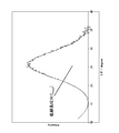
- the diffraction angle 2 ⁇ is around 26 ° (for example, 23.0 °) in the XRD pattern by the CuK ⁇ ray.
- the (002) diffraction line of carbon appears in the range of 27.0 ° or less).
- the carbon (002) diffraction line may include a (002) diffraction line derived from a graphite structure which is a high crystalline component and one or two (002) diffraction lines derived from a low crystalline component.
- the carbon (002) diffraction peak near the diffraction angle 2 ⁇ of 26 ° is separated into three diffraction peaks, that is, two diffraction peaks f broad and f middle of the low crystal component and diffraction peaks of the high crystal component. It can be separated into f narrow .
- the broad peak fbroad is defined as a diffraction peak whose diffraction angle 2 ⁇ is 24.0 ° ⁇ 4.0 ° and whose full width at half maximum is 10.0 ° ⁇ 7.0 °.
- Middle peak f middle is defined as a diffraction peak whose diffraction angle 2 ⁇ is 26.2 ° ⁇ 0.3 ° and whose full width at half maximum is 2.0 ° ⁇ 0.99 °.
- a narrow peak f narrow is defined as a diffraction peak whose diffraction angle 2 ⁇ is 26.5 ° ⁇ 0.5 ° and whose full width at half maximum is 0.3 ° ⁇ 0.2 °.
- K is a Scherrer constant (0.94)
- ⁇ is a wavelength of CuK ⁇ line (0.15418 nm)
- ⁇ is a full width at half maximum (radian)
- ⁇ is a Bragg angle (radian) is there.
- the crystallite size Lc of the carbon structure of the present catalyst is preferably in the range of 0.90 nm or more and 1.20 nm or less.
- the fact that the crystallite size Lc of the carbon structure of the present catalyst is within the above specific range contributes to the excellent catalytic activity of the present catalyst. That is, when the number of active points contained in the carbon structure of the carbon catalyst increases, the interaction between the network surfaces of the carbon structure weakens, and the number of stacked layers of the network surface decreases, and as a result, the crystallites of the carbon structure The size Lc is smaller.
- the fact that the crystallite size Lc of the carbon structure of the present catalyst is within the above-mentioned specific range, in particular below the above-mentioned specific upper limit, means that there are many active points contained in the carbon structure, that is, the present catalyst Show high catalytic activity.
- the carbon structure of the present catalyst preferably shows 90 ⁇ mol / g or less, more preferably 86 ⁇ mol / g or less, as CO 2 desorption amount from 650 ° C. to 1200 ° C. in the above TPD, and more preferably 80 ⁇ mol / g. It is still more preferable to show the following, and it is particularly preferable to show 70 ⁇ mol / g or less.
- the carbon structure of the present catalyst can be defined by arbitrarily combining each of the crystal size Lc ranges described above with each of the CO 2 desorption threshold values described above.
- the carbon structure of the present catalyst has, for example, the above-mentioned crystallite size Lc within the range of 0.90 nm or more and 1.20 nm or less, and exhibits the above-mentioned CO 2 desorption amount of 90 ⁇ mol / g or less It is more preferable to show 86 ⁇ mol / g or less, even more preferable to show 80 ⁇ mol / g or less, and it is particularly preferable to show 70 ⁇ mol / g or less.
- the present catalyst has a carbon structure having a crystallite size Lc in the above specific range, and exhibits a value below the above specified threshold as a CO 2 desorption amount from 650 ° C. to 1200 ° C. in the above TPD, It has excellent catalytic activity and excellent durability.
- the lower limit value of the CO 2 desorption amount of the present catalyst is not particularly limited, but the CO 2 desorption amount from 650 ° C. to 1200 ° C. indicated by the carbon structure of the present catalyst in the TPD is 5 ⁇ mol / g or more It may be
- the present catalyst according to another aspect of the present embodiment has a diffraction angle 2 ⁇ of 24.0 ° ⁇ 4. 4 obtained by separating a diffraction peak at a diffraction angle 2 ⁇ of around 26 ° in the XRD pattern of powder XRD by CuK ⁇ ray. of 0 ° diffraction peak f crystallite size Lc calculated using the Bragg angle of broad or more 0.80 nm, it is within the scope of the following 1.20 nm, up to 1200 ° C. from 25 ° C. carbon monoxide (CO) removal in TPD for measuring the amount of released and CO 2 desorption amount, the sum of CO desorption amount and CO 2 desorption amount of up to 1200 ° C. from 650 ° C. (hereinafter, referred to as "(CO + CO 2) desorption amount".) 647 ⁇ mol It contains a carbon structure showing / g or less.
- the crystallite size Lc of the carbon structure of the present catalyst is preferably in the range of 0.90 nm or more and 1.20 nm or less.
- the carbon structure of the present catalyst preferably shows 635 ⁇ mol / g or less, more preferably 620 ⁇ mol / g or less, as the (CO + CO 2 ) desorption amount from 650 ° C. to 1200 ° C. in the above TPD. It is still more preferable to show not more than / g, and it is particularly preferable to show not more than 580 ⁇ mol / g.
- the carbon structure of the present catalyst can be defined by arbitrarily combining each of the above-described crystal size Lc range and each of the above-described (CO + CO 2 ) desorption threshold values.
- the carbon structure of the present catalyst has the above-mentioned crystallite size Lc in the range of 0.90 nm or more and 1.20 nm or less, and shows the above (CO + CO 2 ) desorption amount of 635 ⁇ mol / g or less Is more preferably 620 ⁇ mol / g or less, still more preferably 600 ⁇ mol / g or less, and particularly preferably 580 ⁇ mol / g or less.
- the present catalyst has a carbon structure having a crystallite size Lc in the above specific range, and exhibits a value below the above specified threshold as a (CO + CO 2 ) desorption amount from 650 ° C. to 1200 ° C. in the above TPD In particular, they have excellent catalytic activity and excellent durability.
- the lower limit of the (CO + CO 2) desorption amount of the catalyst is not particularly limited, (CO + CO 2) desorption amount of carbon structures of the catalyst to 1200 ° C. from 650 ° C. showing in the TPD is, 45 ⁇ mol / g It is good also as it being more than.
- this catalyst has a crystallite size Lc in the range of 0.80 nm to 1.20 nm, and is a temperature-programmed desorption that measures the CO desorption amount and the CO 2 desorption amount from 25 ° C. to 1200 ° C.
- a carbon structure showing a CO 2 desorption amount of 97 ⁇ mol / g or less and a (CO + CO 2 ) desorption amount of 647 ⁇ mol / g or less from 650 ° C. to 1200 ° C. may be included.
- the carbon structure of the present catalyst can arbitrarily select each of the crystal size Lc range described above, each of the CO 2 desorption threshold described above, and each of the (CO + CO 2 ) desorption threshold described above. It can be combined and defined.
- the carbon structure of the present catalyst has, for example, the crystallite size Lc in the range of 0.90 nm to 1.20 nm, and the CO 2 desorption amount of 90 ⁇ mol / g or less and the CO elimination It is preferable to show a total of 635 ⁇ mol / g or less of separation amount and CO 2 desorption amount, and a total of 620 ⁇ mol / g or less of the above CO 2 desorption amount of 86 ⁇ mol / g or less and the above CO desorption amount and CO 2 desorption amount It is more preferable to show the CO 2 desorption amount of 80 ⁇ mol / g or less and the total of the CO desorption amount and the CO 2 desorption amount of 600 ⁇ mol / g or less, and the CO 2 desorption amount It is particularly preferable to show 70 ⁇ mol / g or less and a total of 580 ⁇ mol / g or less of the CO desorption amount and the CO 2 desorption amount.
- the present catalyst according to still another aspect of the present embodiment has a diffraction angle 2 ⁇ of 24.0 ° ⁇ 4 obtained by separating a diffraction peak at a diffraction angle 2 ⁇ of around 26 ° in the XRD pattern of powder XRD by CuK ⁇ ray. .0 ° of the diffraction peak f broad crystallite size Lc calculated using the Bragg angle of not less than 0.80 nm, in the range of less 1.20 nm, measured CO desorption amount of up to 1200 ° C. from 25 ° C.
- the TPD contains a carbon structure having a CO desorption amount of 549 ⁇ mol / g or less from 650 ° C. to 1200 ° C.
- the crystallite size Lc of the carbon structure of the present catalyst is preferably in the range of 0.90 nm or more and 1.20 nm or less.
- the carbon structure of the present catalyst preferably shows 547 ⁇ mol / g or less, and particularly preferably 545 ⁇ mol / g or less, as CO desorption amount from 650 ° C. to 1200 ° C. in the above TPD.
- the carbon structure of the present catalyst can be defined by arbitrarily combining each of the above-described crystal size Lc range and each of the above-described CO desorption threshold values.
- the crystallite size Lc is preferably in the range of 0.90 nm or more and 1.20 nm or less, and preferably indicates the CO desorption amount of 547 ⁇ mol / g or less, It is particularly preferable to show 545 ⁇ mol / g or less.
- the present catalyst has a carbon structure having a crystallite size Lc in the above specific range, and exhibits a CO desorption amount from 650 ° C. to 1200 ° C. in the above TPD by showing a value equal to or less than the above specified threshold. It has excellent catalytic activity and excellent durability.
- the lower limit value of the CO desorption amount of the present catalyst is not particularly limited, but the CO desorption amount from 650 ° C. to 1200 ° C. indicated by the carbon structure of the present catalyst in the TPD is 40 ⁇ mol / g or more. Good.
- the present catalyst has a crystallite size Lc in the range of 0.80 nm to 1.20 nm, and in TPD for measuring the amount of CO desorption and the amount of CO 2 desorption from 25 ° C. to 1200 ° C. It is also possible to include a carbon structure exhibiting a CO desorption amount of 549 ⁇ mol / g or less and a CO 2 desorption amount of 97 ⁇ mol / g or less from 650 ° C. to 1200 ° C. In this case, the carbon structure of the present catalyst is an arbitrary combination of each of the crystal size Lc range described above, each of the CO desorption threshold described above, and each of the CO 2 desorption threshold described above. , Can be defined.
- the carbon structure of the present catalyst has, for example, the crystallite size Lc in the range of 0.90 nm to 1.20 nm, and the CO desorption amount of 547 ⁇ mol / g or less, and the CO 2 desorption. It is preferable to indicate a separation amount of 90 ⁇ mol / g or less, more preferably 547 ⁇ mol / g or less of the CO, and 86 ⁇ mol / g or less of the CO 2 release, and 545 ⁇ mol / g or less of the CO desorption amount.
- this catalyst has a crystallite size Lc in the range of 0.80 nm to 1.20 nm, and is a temperature-programmed desorption that measures the CO desorption amount and the CO 2 desorption amount from 25 ° C. to 1200 ° C.
- the separation method it is possible to include a carbon structure showing a CO desorption amount of 549 ⁇ mol / g or less and a (CO + CO 2 ) desorption amount of 647 ⁇ mol / g or less from 650 ° C. to 1200 ° C.
- the carbon structure of the present catalyst is an arbitrary combination of each of the crystal size Lc range described above, each of the CO desorption threshold described above, and each of the (CO + CO 2 ) desorption threshold described above. Can be defined.
- the carbon structure of the present catalyst has, for example, the crystallite size Lc in the range of 0.90 nm or more and 1.20 nm or less, and the CO desorption amount of 547 ⁇ mol / g or less, and (CO + CO 2 )
- the amount of desorption is preferably 635 ⁇ mol / g or less, more preferably 547 ⁇ mol / g or less of CO and 620 ⁇ mol / g or less of (CO + CO 2 ), more preferably 545 ⁇ mol / g of CO g or less and the (CO + CO 2) is even more preferred to exhibit less desorption amount 600 [mu] mol / g, or less than the CO desorption amount 545Myumol / g and the (CO + CO 2) in particular to exhibit less desorption amount 580Myumol / g preferable.
- this catalyst has a crystallite size Lc in the range of 0.80 nm to 1.20 nm, and is a temperature-programmed desorption that measures the CO desorption amount and the CO 2 desorption amount from 25 ° C. to 1200 ° C.
- the carbon structure showing a CO desorption amount of 549 ⁇ mol / g or less from 650 ° C. to 1200 ° C., a CO 2 desorption amount of 97 ⁇ mol / g or less, and a (CO + CO 2 ) desorption amount of 647 ⁇ mol / g or less It is also good.
- the carbon structure of the present catalyst includes each of the crystal size Lc range described above, each of the CO desorption threshold described above, and each of the CO 2 desorption threshold described above (CO + CO 2 And.) Any combination with each of the desorption threshold values can be defined.
- the carbon structure of the present catalyst has, for example, the crystallite size Lc in the range of 0.90 nm to 1.20 nm, and the CO desorption amount of 547 ⁇ mol / g or less, the CO 2 desorption It is preferable to show the separated amount of 90 ⁇ mol / g or less and the above (CO + CO 2 ) desorption amount of 635 ⁇ mol / g or less, the above CO desorption amount of 547 ⁇ mol / g or less, the above CO 2 desorption amount of 86 ⁇ mol / g or less and the above (CO + CO 2 ) It is more preferable to indicate the desorption amount of 620 ⁇ mol / g or less, and the CO desorption amount of 545 ⁇ mol / g or less, the CO 2 desorption amount of 80 ⁇ mol / g or less and the (CO + CO 2 ) desorption amount of 600 ⁇ mol / g or less and even more preferably, the CO desorption amount 545 ⁇ mol /
- the carbon catalyst is heated in the temperature range of 25 ° C. to 1200 ° C. without performing the heat treatment for desorbing the functional group and the subsequent oxygen adsorption.
- the amount of carbon monoxide (CO) and / or carbon dioxide (CO 2 ) eliminated from the carbon catalyst is measured.
- the CO desorption amount and / or the CO 2 desorption amount in TPD which is defined as one of the characteristics of the present catalyst, reflects the quality and the amount of the oxygen-containing functional group contained in the carbon structure of the present catalyst. That is, the present catalyst has a carbon structure having a small content of oxygen-containing functional groups such that the CO desorption amount and / or the CO 2 desorption amount in the above specific temperature range is less than the above specific threshold in the above TPD. Have.
- the small content of the oxygen-containing functional group in the carbon structure of the present catalyst contributes to the excellent durability of the present catalyst.
- the electrochemical oxidative degradation of the carbon structure proceeds in a sequential oxidation reaction starting from the oxygen-containing functional group. Therefore, reducing the content in the carbon structure of the oxygen-containing functional group that can be the starting point of oxidative deterioration will reduce the deterioration initiation point of the carbon structure, which contributes to the improvement of the durability of the carbon structure. It is thought that.
- the inventors of the present invention have, among oxygen functional groups, in particular, TPD that causes the elimination of CO and / or the elimination of CO 2 in a specific temperature range from 650 ° C. to 1200 ° C. It has been found that the oxygen functional group greatly affects the durability of the carbon catalyst.
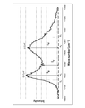
- This catalyst has a ratio of the minimum intensity between the G band and the D band near 1360 cm ⁇ 1 to the intensity of the G band near 1580 cm ⁇ 1 in the Raman spectrum obtained by Raman spectroscopy (hereinafter referred to as “I v / I g ratio "hereinafter.) 0.30 or more, may include carbon structure showing 0.49 or less.
- the G band is a component derived from an ideal graphite structure
- the D band is a component derived from a curved structure including a defect and an edge.
- the minimum intensity I v between G band and D band is dependent on the components derived from amorphous.
- the I v / I g ratio is the ratio of the amount of amorphous to the amount of ideal graphite structure.
- the carbon catalyst is easily deteriorated if the amount of the amorphous phase is too large, so it is considered that an optimal range exists in the I v / I g ratio.
- the fact that the I v / I g ratio of the carbon structure of the present catalyst is within the above-mentioned specific range contributes to the excellent catalytic activity of the present catalyst.
- the present catalyst may include a carbon structure having a D-band half width of about 179 cm -1 or less in the vicinity of 1360 cm -1 in a Raman spectrum obtained by Raman spectroscopy.
- the Raman spectrum obtained by Raman spectroscopy of the catalyst 1360 cm around -1 (e.g., 1250 cm -1 or more, 1400 cm -1 or less) is, D band with a 179cm -1 or less of the half-value width is detected Ru.
- the half width of the D band is calculated from the following equation:
- the half width of the D band (cm ⁇ 1 ) (A d ⁇ B d ) ⁇ 2 (in this formula, A d is the intensity I d of the D band Wave number (cm ⁇ 1 ) corresponding to the peak top of D band, and B d is a wave number (cm cm) corresponding to a Raman spectrum showing half the intensity of the D band intensity I d on the lower wave number side than the A d -1 )).
- the half width of the D band indicates the crystallinity of the curved structure included in the carbon structure. That is, the smaller half width of the D band means that the crystallinity of the curved structure is high. Therefore, the fact that the D-band half-width of the carbon structure of the present catalyst is less than or equal to the specific threshold value means that the carbon structure includes a highly crystalline curved structure. And, having the carbon structure including the highly crystalline curved structure has a contribution to the excellent durability of the present catalyst.
- the lower limit value of the above-mentioned D band half width of the present catalyst is not particularly limited, the D band half width may be 80 cm -1 or more.
- the catalyst in the Raman spectrum obtained by Raman spectroscopy, may include a half-value width 80 cm -1 carbon structure having the following G band near 1580 cm -1.
- the Raman spectrum obtained by Raman spectroscopy of the catalyst 1580 cm around -1 (e.g., 1550 cm -1 or more, 1650 cm -1 or less) is detected G band having a 80 cm -1 or less half width Ru.
- the half bandwidth of the G band indicates the crystallinity of the graphite structure included in the carbon structure. That is, the fact that the half width of the G band is small means that the crystallinity of the graphite structure is high. Therefore, the fact that the G-band half width of the carbon structure of the present catalyst is less than the above-mentioned specific threshold value means that the carbon structure contains a highly crystalline graphite structure. And, the catalyst having a carbon structure including a highly crystalline graphite structure contributes to the excellent durability of the catalyst.
- the lower limit value of the half width of the G band of the present catalyst is not particularly limited, but the G band half width may be 40 cm ⁇ 1 or more.
- the catalyst may contain a metal.
- the metal contained in the present catalyst is not particularly limited as long as the above-described characteristics of the present catalyst can be obtained, but it is preferably a transition metal.
- the catalyst preferably contains two or more metals, and preferably contains two or more transition metals.
- the transition metal is a metal belonging to Groups 3 to 12 of the periodic table, and preferably a transition metal belonging to the fourth period of Groups 3 to 12 of the periodic table.
- the transition metal contained in the present catalyst includes, for example, scandium (Sc), titanium (Ti), vanadium (V), chromium (Cr), manganese (Mn), iron (Fe), cobalt (Co), Nickel (Ni), copper (Cu), zinc (Zn), yttrium (Y), zirconium (Zr), niobium (Nb), molybdenum (Mo), ruthenium (Ru), rhodium (Rh), palladium (Pd), Silver (Ag), lanthanoids (eg, one or more selected from the group consisting of neodymium (Nd), samarium (Sm) and gadolinium (Gd)) and actinides, or Sc, Ti, V, Cr, Mn , Fe, Co, Ni, Cu,
- the present catalyst preferably contains one or more selected from the group consisting of Ti, Cr, Fe, Zn, Nd, Sm and Gd, and more preferably contains two or more selected from the group .
- the catalyst may include, for example, one or more selected from the group consisting of Fe and Zn, and may include Fe and Zn.
- the catalyst may further contain another transition metal. That is, for example, when the present catalyst contains one or more or two or more first transition metals selected from the group consisting of Ti, Cr, Fe, Zn, Nd, Sm and Gd, Sc, Ti, V, Cr, Mn, Fe, Co, Ni, Cu, Zn, Y, Zr, Nb, Mo, Ru, Rh, Pd, Ag, lanthanoids (for example, one or more selected from the group consisting of Nd, Sm and Gd) And actinoids, or from Sc, Ti, V, Cr, Mn, Fe, Co, Ni, Cu, Zn, Y, Zr, Nb, Mo, Ag, lanthanoids (eg, Nd, Sm and Gd)
- One or more selected from the group consisting of actinides and one or more selected from actinides may be further included a second transition metal different from the first transition metal.
- the present catalyst may not contain platinum (Pt).
- the catalyst is one selected from the group consisting of platinum (Pt), ruthenium (Ru), rhodium (Rh), palladium (Pd), iridium (Ir), gold (Au) and osmium (Os). The above may not be included.
- the catalyst contains a metal derived from the carbonization raw material described later
- the catalyst contains the metal inside due to the metal being contained in the carbonization raw material. That is, even when the present catalyst is produced through the metal removal treatment described later, a trace amount of raw material-derived metal remains inside the present catalyst.
- the present catalyst containing a metal when the present catalyst containing a metal is in the form of particles, when the particles constituting the present catalyst are cut, the metal is detected in the cross section of the particles exposed by the cutting.
- the metals contained in the present catalyst can be detected, for example, by inductively coupled plasma (ICP) emission spectroscopy.
- ICP inductively coupled plasma
- the catalyst may have a specific surface area of 800 m 2 / g or more as measured by the BET method.
- the specific surface area of this catalyst is preferably 1000 m 2 / g or more, particularly preferably 1200 m 2 / g or more.
- the specific surface area of the present catalyst is equal to or more than the above-mentioned specific threshold value, it contributes to the improvement of the chemical reaction by the present catalyst and contributes to the excellent catalytic activity.
- the upper limit value of the specific surface area of the present catalyst is not particularly limited, but the specific surface area may be 3000 m 2 / g or less.
- the catalyst is referred to as a “N / C ratio” as a ratio of nitrogen atom concentration (atm%) to carbon atom concentration (atm%) measured by X-ray photoelectron spectroscopy (hereinafter “XPS”). )
- XPS X-ray photoelectron spectroscopy
- a carbon structure showing 1.5% or more may be included.
- the N / C ratio of the carbon structure of the present catalyst is preferably 1.8% or more, and particularly preferably 2.0% or more.
- the fact that the N / C ratio of the carbon structure of the present catalyst is equal to or higher than the above-mentioned specific threshold value means that the carbon structure contains a large amount of nitrogen-containing functional groups on the surface, and the excellent catalyst of the present catalyst Contribute to activity.
- the upper limit value of the N / C ratio of the present catalyst is not particularly limited, but the N / C ratio may be 15.0% or less.
- the catalyst may include a carbon structure exhibiting a nitrogen atom content of at least 1.5% by weight as measured by elemental analysis by a combustion method.
- the nitrogen atom content of the carbon structure of the present catalyst is preferably 1.8% by weight or more, and particularly preferably 2.0% by weight or more.
- the fact that the nitrogen atom content of the carbon structure of the present catalyst is equal to or more than the specific threshold value means that the carbon structure contains a large amount of nitrogen-containing functional groups, which contributes to the excellent catalytic activity of the present catalyst. Do.
- the upper limit value of the nitrogen atom content of the present catalyst is not particularly limited, but the nitrogen atom content may be 15% by weight or less.
- the catalyst may have an average particle size of 1.0 ⁇ m or less.
- the fact that the average particle size of the present catalyst is less than or equal to the specific threshold contributes to the efficiency of the chemical reaction by the present catalyst, contributes to the excellent catalytic activity of the present catalyst, and the preparation of a battery electrode containing the present catalyst. Contribute to the efficiency of
- the lower limit value of the average particle size of the present catalyst is not particularly limited, but the average particle size may be 0.050 ⁇ m or more.
- the present catalyst may have a maximum particle size of 1000.0 ⁇ m or less.
- the maximum particle size of the present catalyst is, for example, preferably 50.0 ⁇ m or less, and particularly preferably 10.0 ⁇ m or less.
- the catalyst is a carbon catalyst for a fuel cell (for example, a carbon catalyst for a cathode of a fuel cell or for an anode, preferably a carbon catalyst for a cathode of a fuel cell)
- the largest particles of the catalyst The diameter is preferably 50.0 ⁇ m or less, and particularly preferably 10.0 ⁇ m or less.
- the minimum particle size of the present catalyst is not particularly limited, but may be, for example, 0.001 ⁇ m or more.
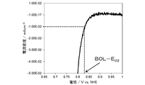
- the present catalyst is a voltage at which a reduction current of -10 ⁇ A / cm 2 flows in an oxygen reduction voltammogram obtained by sweeping and applying a potential using a rotating disk electrode apparatus having a working electrode containing the present catalyst (hereinafter referred to as
- the oxygen reduction onset potential (E 02 ) may be at least 0.810 V (vs. NHE).
- the upper limit of the oxygen reduction onset voltage E 02 of the present catalyst is not particularly limited, but the voltage E 02 may be 1.0 V (vs. NHE) or less.
- the present catalyst has a current density when a voltage of 0.7 V (vs. NHE) is applied in an oxygen reduction voltammogram obtained by sweeping and applying a potential using a rotating disk electrode apparatus having a working electrode containing the present catalyst. It is also possible to indicate (i 0.7 ) ⁇ 1.0 mA / cm 2 or less.
- the lower limit value of the current density i 0.7 (mA / cm 2 ) of the present catalyst is not particularly limited, but the current density i 0.7 may be ⁇ 5.0 mA / cm 2 or more.
- the present catalyst uses a rotating disk electrode device having a working electrode containing the present catalyst, and the state of applying a voltage of 1.2 V (vs. RHE) for 10 minutes for each of the start point and the end point of the durability test.
- vs. RHE a voltage of 1.2 V
- voltammogram obtained by sweeping a potential for 5 cycles in the range of 0.0 V to 1.0 V (vs. NHE) using the rotating disk electrode device, 1.0 V to 0.
- the durability test for the area (hereinafter referred to as “CV area”) of the area surrounded by the curve at the time of potential sweep application to 0 V and the curve at the time of potential sweep application from 0.0 V to 1.0 V Indicates the area increase amount (hereinafter referred to as “CV area increase amount”) 5.70 ⁇ 10 ⁇ 5 A ⁇ sec or less obtained by subtracting the CV area at the end of the durability test from the CV area at the start To be It may be.
- the catalyst preferably shows 5.50 ⁇ 10 ⁇ 5 A ⁇ sec or less, more preferably 5.30 ⁇ 10 ⁇ 5 A ⁇ sec or less, as the CV area increase. It is particularly preferable to show 10 ⁇ 10 ⁇ 5 A ⁇ sec or less.
- the CV area indicates the capacity of the electric double layer in the working electrode containing a carbon catalyst, and reflects the state of pores and the information of surface functional groups contained in the carbon catalyst.
- the large CV area increase means that the deterioration of the carbon catalyst proceeds, the pores and surface functional groups contained in the carbon catalyst change, and the capacity of the electric double layer in the working electrode containing the carbon catalyst increases. Show what you are doing. Therefore, the fact that the CV area increase amount of the present catalyst is less than or equal to the specific threshold value supports the excellent durability of the present catalyst.
- the lower limit value of the CV area increase amount of the present catalyst is not particularly limited, but the CV area increase amount may be 4.50 ⁇ 10 ⁇ 5 A ⁇ sec or more.
- the present catalyst uses a rotating disk electrode device having a working electrode containing the present catalyst, and the state of applying a voltage of 1.2 V (vs. RHE) for 10 minutes for each of the start point and the end point of the durability test.
- the current density i 0.7 (mA / cm 2 ) when a voltage of 0.7 V (vs. NHE) is applied in the oxygen reduction voltammogram obtained by sweeping and applying a potential using the rotating disk electrode device
- the current density i 0.7 can be obtained by multiplying 100 by the value obtained by dividing the current density at the end of the endurance test by the current density at the start of the endurance test. It may be
- the catalyst preferably exhibits 89.0% or more, more preferably 90.0% or more, and preferably 91.0% or more as the current density i 0.7 maintenance rate. Particularly preferred.
- the upper limit value of the current density i 0.7 maintenance rate of the present catalyst is not particularly limited, but the current density i 0.7 maintenance rate may be 95% or less.
- the catalyst is a carbon material which itself has catalytic activity.
- the carbon material constituting the present catalyst is, for example, a carbonized material obtained by carbonization of a raw material containing an organic substance as described later.
- the catalyst is a carbonized material obtained by carbonization of a raw material containing an organic substance and a metal
- the carbon structure of the catalyst contains the metal, but the catalytic activity of the catalyst is higher than that of the metal Is also considered to be mainly due to the active point contained in the carbon structure itself. This means that, even when the present catalyst containing a metal derived from the carbonization raw material is subjected to a metal removal treatment for reducing the content of the metal, the catalytic activity of the present catalyst after the relevant metal removal treatment is the same as that of the present invention.
- the carbon material obtained by supporting the metal after the carbonization on the surface of the carbonized material obtained by carbonization of the raw material containing organic matter and containing no metal compared with that before the metal removal treatment This is supported by having no excellent catalytic activity as in the present catalyst.
- the catalyst activity of the present catalyst is, for example, an oxidation activity and / or a reduction activity, more specifically, an oxygen reduction activity and / or a hydrogen oxidation activity.
- the catalyst itself has catalytic activity alone, it may not contain Pt or contain a rare metal such as Pt, but the present invention is not limited to this, and for example, the catalyst contains the rare metal. It may be used as a carrier to be supported.
- the rare metal supported by the present catalyst is, for example, one or more selected from the group consisting of Pt, Ru, Rh, Pd, Ir, Au and Os.
- the present catalyst even when used as a carrier of a rare metal, the present catalyst (the present catalyst before supporting the rare metal) itself as a carrier not carrying the rare metal is itself It is a carbon material having catalytic activity, that is, a carbon catalyst.
- the method for producing the present catalyst is not particularly limited as long as the present catalyst having the characteristics described above can be obtained, but in the present embodiment, a method including carbonizing the raw material containing the organic substance under pressure is described Do.
- the organic substance contained in the raw material is not particularly limited as long as it can be carbonized. That is, as the organic substance, for example, a high molecular weight organic compound (for example, a resin such as a thermosetting resin and / or a thermoplastic resin) and / or a low molecular weight organic compound are used. Alternatively, biomass may be used as the organic matter.
- a high molecular weight organic compound for example, a resin such as a thermosetting resin and / or a thermoplastic resin
- biomass may be used as the organic matter.
- a nitrogen-containing organic matter is preferably used as the organic matter.
- the nitrogen-containing organic substance is not particularly limited as long as it is an organic substance containing an organic compound containing a nitrogen atom in its molecule.
- the present catalyst is a carbonized material obtained by carbonization of a raw material containing a nitrogen-containing organic substance, the carbon structure of the present catalyst contains a nitrogen atom.
- organic substance for example, polyacrylonitrile, polyacrylonitrile-polyacrylic acid copolymer, polyacrylonitrile-polyacrylic acid methyl copolymer, polyacrylonitrile-polymethacrylic acid copolymer, polyacrylonitrile-polymethacrylic acid -Polymethallyl sulfonic acid copolymer, polyacrylonitrile-polymethyl methacrylate copolymer, phenol resin, polyfurfuryl alcohol, furan, furan resin, phenol formaldehyde resin, melamine, melamine resin, epoxy resin, nitrogen-containing chelate resin ( For example, one or more selected from the group consisting of polyamine type, iminodiacetic acid type, amino phosphoric acid type and aminomethylphosphonic acid type), polyamide imide resin, pyrrole, polypyrrole, polyvinylpyrrole, -Methylpolypyrrole, acrylonitrile, polyvinylidene chloride
- the content of the organic substance in the raw material is not particularly limited as long as the present catalyst can be obtained, but may be, for example, 5% by mass or more and 90% by mass or less, preferably 10% by mass or more and 80% by mass. % Or less.
- the carbonization raw material may further contain a metal. That is, in this case, the raw material containing the organic substance and the metal is carbonized under pressure.
- the catalyst is a carbonized material obtained by carbonization of a raw material containing an organic substance and a metal, the catalyst contains the metal.
- the metal contained in the raw material is preferably a transition metal. Moreover, it is preferable that a raw material contains 2 or more types of metals, and it is preferable that 2 or more types of transition metals are included.
- the transition metal is a metal belonging to Groups 3 to 12 of the periodic table, and preferably a transition metal belonging to the fourth period of Groups 3 to 12 of the periodic table.
- transition metals contained in the raw material are, for example, Sc, Ti, V, Cr, Mn, Fe, Co, Ni, Cu, Zn, Y, Zr, Nb, Mo, Ru, Rh, Pd, Ag, A lanthanoid (for example, one or more selected from the group consisting of Nd, Sm and Gd) and an actinide, or Sc, Ti, V, Cr, Mn, Fe, Co, Ni, Cu, Zn, Y, Zr , Nb, Mo, Ag, lanthanoid (for example, one or more selected from the group consisting of Nd, Sm and Gd), and actinide may be one or more selected from the group It is good also as it being 2 or more types.
- the raw material preferably contains one or more selected from the group consisting of Ti, Cr, Fe, Zn, Nd, Sm and Gd, and more preferably contains two or more selected from the group.
- the raw material may include, for example, one or more selected from the group consisting of Fe and Zn, and may include Fe and Zn.
- the raw material may further contain other transition metals. That is, for example, when the raw material contains one or more or two or more first transition metals selected from the group consisting of Ti, Cr, Fe, Zn, Nd, Sm and Gd, Sc, Ti, V, Cr Mn, Fe, Co, Ni, Cu, Zn, Y, Zr, Nb, Mo, Ru, Rh, Pd, Ag, lanthanoids (for example, one or more selected from the group consisting of Nd, Sm and Gd), and Selected from the group consisting of actinides, or Sc, Ti, V, Cr, Mn, Fe, Co, Ni, Cu, Zn, Y, Zr, Nb, Mo, Ag, lanthanoids (eg, Nd, Sm and Gd) And at least one selected from the group consisting of actinides, and may further include a second transition metal different from the first transition metal.
- first transition metals selected from the group consisting of Ti, Cr, Fe, Zn, Nd, Sm and Gd,
- the raw material may not contain Pt.
- the raw material may not contain one or more selected from the group consisting of Pt, Ru, Rh, Pd, Ir, Au and Os.
- metal contained in the raw material a single substance of the metal and / or a compound of the metal are used.
- the metal compound for example, one or more selected from the group consisting of metal salts, metal oxides, metal hydroxides, metal nitrides, metal sulfides, metal carbides and metal complexes may be used.
- the content of the metal in the raw material (the total of the content of the two or more metals when two or more metals are used) is not particularly limited as long as the present catalyst can be obtained, for example, It may be 1% by mass or more and 90% by mass or less, and preferably 2% by mass or more and 80% by mass or less.
- Carbonization is performed by heating a raw material under pressure and holding the raw material at a temperature at which the raw material is carbonized (hereinafter, referred to as “carbonization temperature”).
- the carbonization temperature is not particularly limited as long as the raw material is carbonized, and is, for example, 300 ° C. or more. That is, in this case, the raw material containing the organic matter is carbonized at a temperature of 300 ° C. or higher under pressure.
- the carbonization temperature may be, for example, 700 ° C. or higher, preferably 900 ° C. or higher, more preferably 1000 ° C. or higher, and particularly preferably 1100 ° C. or higher.
- the upper limit of the carbonization temperature is not particularly limited, but the carbonization temperature is, for example, 3000 ° C. or less.
- the temperature rising rate to the carbonization temperature is, for example, 0.5 ° C./min or more and 300 ° C./min or less.
- the time to hold the raw material at the carbonization temperature is, for example, 1 second or more and 24 hours or less, preferably 5 minutes or more and 24 hours or less.
- Carbonization is preferably performed in an inert gas atmosphere such as a nitrogen atmosphere. That is, carbonization is preferably performed, for example, under the flow of an inert gas such as nitrogen gas.
- the pressure of the atmosphere under which the carbonization is performed is not particularly limited as long as it is a pressure higher than the atmospheric pressure, and for example, it is a pressure of 0.05 MPa or more in gauge pressure.
- the pressure of the atmosphere for carbonization may be 0.15 MPa or more as gauge pressure, preferably 0.20 MPa or more, more preferably 0.40 MPa or more, 0.50 MPa It is particularly preferable to be the above. That is, in these cases, the raw material containing the organic matter is carbonized under a pressure at which the gauge pressure is equal to or higher than the threshold (MPa).
- the method for producing the catalyst may further include subjecting the carbonized material obtained by the carbonization to a further treatment. That is, for example, the carbonized material may be subjected to at least one treatment selected from the group consisting of ammonia treatment, hydrogen treatment, and O-alkylation treatment.
- the raw material containing the organic matter is carbonized under pressure, and then the carbonized material obtained by the carbonization is one selected from the group consisting of ammonia treatment, hydrotreating, and O-alkylation treatment. The above processing is performed.
- the ammonia treatment is not particularly limited as long as the carbonization material is brought into contact with ammonia. That is, the ammonia treatment is, for example, a treatment of heating the carbonized material in an ammonia-containing gas atmosphere.
- the ammonia content of the ammonia-containing gas is not particularly limited as long as the effect of the ammonia treatment can be obtained, but may be, for example, 0.1% by volume or more, and 1.0% by volume or more. It may be 3.0 vol% or more.
- the temperature at which the carbonized material is heated during the ammonia treatment is not particularly limited as long as the effect of the ammonia treatment can be obtained, but may be, for example, 300 ° C. or more, and 500 ° C. or more Preferably, the temperature is 700 ° C. or higher.
- the upper limit of the heating temperature is not particularly limited, but the heating temperature may be, for example, 1300 ° C. or less, and preferably 1000 ° C. or less.
- the range of the heating temperature during the ammonia treatment is defined by arbitrarily combining each of the lower limits described above and each of the upper limits described above.
- the hydrogen treatment is not particularly limited as long as the carbonized material is brought into contact with hydrogen. That is, the hydrogen treatment is, for example, a treatment of heating the carbonized material in a hydrogen-containing gas atmosphere.
- the hydrogen content of the hydrogen-containing gas is not particularly limited as long as the effect of the hydrogen treatment can be obtained, but may be, for example, 0.1% by volume or more, and 1.0% by volume or more. It may be 3.0 vol% or more.
- the temperature at which the carbonized material is heated during the hydrogen treatment is not particularly limited as long as the effect of the hydrogen treatment can be obtained, but may be, for example, 300 ° C. or higher, and 500 ° C. or higher. Preferably, the temperature is 700 ° C. or higher.
- the upper limit of the heating temperature is not particularly limited, but the heating temperature may be, for example, 1300 ° C. or higher, and preferably 1000 ° C. or higher.
- the range of heating temperature during the hydrogen treatment is defined by arbitrarily combining each of the lower limits described above and each of the upper limits described above.
- the O-alkylation treatment is not particularly limited as long as the carbon structure of the carbonized material is subjected to O-alkylation.
- the O-alkylation treatment is, for example, an O-methylation treatment or an O-ethylation treatment.
- the O-methylation treatment is, for example, a treatment in which the carbonized material is brought into contact with trimethylsilyldiazomethane in an inert gas atmosphere such as nitrogen gas under light shielding.
- the carbonized material may be subjected to a metal removal treatment.
- the raw material containing the organic matter is carbonized under pressure, and then the carbonized material obtained by the carbonization is subjected to a metal removal treatment.
- a raw material containing an organic substance is carbonized under pressure, and then the carbonized material obtained by the carbonization is subjected to a metal removal treatment, and then the carbonized material after the metal removal treatment is ammonia,
- One or more treatments selected from the group consisting of treatment, hydrogen treatment, and O-alkylation treatment are applied.
- the metal removal treatment is a treatment to reduce the amount of metal derived from the raw material contained in the carbonized material.
- the metal removal process is, for example, an acid cleaning process and / or an electrolytic process.
- the present electrode includes the present catalyst described above. That is, the present electrode is, for example, a battery electrode on which the present catalyst is supported. Specifically, the present electrode is, for example, a battery electrode including an electrode base and the present catalyst supported on the electrode base.
- the present electrode may not contain Pt, or may not contain the above-mentioned rare metals such as Pt, but is limited thereto.
- the present electrode may include the present catalyst as a carrier supporting the rare metal, and the rare metal supported by the present catalyst.
- the present electrode is, for example, an electrode of a fuel cell (for example, a polymer electrolyte fuel cell), an air cell, a water electrolytic cell (for example, a polymer electrolyte water electrolytic cell), a redox flow cell, or a halogen cell.
- a fuel cell for example, a polymer electrolyte fuel cell
- an air cell for example, a water electrolytic cell (for example, a polymer electrolyte water electrolytic cell), a redox flow cell, or a halogen cell.
- a water electrolytic cell for example, a polymer electrolyte water electrolytic cell
- a redox flow cell for example, a redox flow cell
- a halogen cell for example, a halogen cell.
- the present electrode is, for example, a cathode or an anode, preferably a cathode.
- the present electrode is a cathode or an anode of a fuel cell, an air cell, a water electrolytic cell, a redox flow cell, or a halogen cell, preferably a fuel cell cathode, an air cell cathode, a water electrolytic cell cathode, a redox flow cell cathode, Or it is a halogen battery cathode.
- the battery includes the battery electrode described above. That is, the present cell is, for example, a fuel cell (for example, a polymer electrolyte fuel cell) including the present electrode, an air cell, a redox flow cell, or a halogen cell.
- the present battery may have a membrane / electrode assembly including the present electrode.
- the present battery is a battery having the present electrode as a cathode or an anode, preferably a battery having the present electrode as a cathode.
- the present cell is a fuel cell, an air cell, a redox flow cell, or a halogen cell having the present electrode as a cathode or an anode, preferably a fuel cell, an air cell, a redox flow cell, or a halogen having the present electrode as a cathode. It is a battery.
- Example 1 1.0 g of polyacrylonitrile (PAN), 1.0 g of 2-methylimidazole, 6.0 g of zinc chloride (ZnCl 2 ) and 30 g of dimethylformamide were mixed. The solvent was removed from the resulting mixture by drying. The dried mixture was heated in air to infusibilize at 250 ° C.
- Carbonization was carried out by heating and keeping the dried mixture at 1100 ° C. under a nitrogen atmosphere and a gauge pressure of 0.9 MPa.
- Diluted hydrochloric acid was added to the carbonized material obtained by carbonization and stirred.
- the suspension containing the carbonized material was then filtered using a filtration membrane and the carbonized material was washed with distilled water until the filtrate was neutral.
- the metal removal treatment by acid cleaning was performed.
- the carbonized material after metal removal treatment was pulverized by a pulverizer until the average particle size became 1 ⁇ m or less.
- the pulverized carbonized material was obtained as a carbon catalyst of Example 1.
- Example 2 The carbon catalyst obtained in Example 1 described above was heated and held at 900 ° C. for 1 hour in an atmosphere in which 100% ammonia gas was circulated at 0.3 L / min. Thereafter, ammonia gas was replaced with nitrogen, and the carbon catalyst was kept at 500 ° C. for 10 minutes in a nitrogen atmosphere. Then, a carbon catalyst cooled by natural cooling in a nitrogen atmosphere was obtained as a carbon catalyst of Example 2.
- Example 3 By heating ammonium hydrogen carbonate at 150 ° C. in a nitrogen gas flow, a mixed gas containing ammonia, carbon dioxide and water vapor was generated.
- Example 3 The carbon catalyst obtained in Example 1 described above was heated and maintained at 900 ° C. for 1 hour while flowing the mixed gas generated as described above in a nitrogen atmosphere. Thereafter, the mixed gas was replaced with nitrogen, and a carbon catalyst cooled by natural cooling in a nitrogen atmosphere was obtained as a carbon catalyst of Example 3.
- Example 4 The carbon catalyst obtained in Example 1 described above was heated and held at 900 ° C. for 1 hour in a 100% hydrogen atmosphere. Thereafter, a carbon catalyst cooled by natural cooling in a hydrogen atmosphere was obtained as a carbon catalyst of Example 4.
- Example 5 1.0 g of the carbon catalyst obtained in Example 1 described above was mixed with 100 mL of commercially available super dehydrated methanol, and the obtained mixture was treated with ultrasonic waves for 2 minutes while being stirred. The mixture after sonication was mixed with a 1.0 M trimethylsilyldiazomethane / hexane solution in a nitrogen atmosphere under light shielding and stirred for 15 hours. Then, the solvent was removed from the mixture by drying. Thus, the dried carbon catalyst was obtained as the carbon catalyst of Example 5.
- Example 6 Before infusibilization, a mixture further containing 0.018 g of chromium chloride hexahydrate (CrCl 3 .6H 2 O) was prepared, and in the same manner as Example 2 above, except that the mixture was infusibilized. The carbon catalyst of Example 6 was obtained.
- Example 7 Before infusibilization, a mixture further containing 0.018 g of chromium chloride hexahydrate (CrCl 3 .6H 2 O) was prepared, and the same as Example 3 above except that the mixture was infusibilized The carbon catalyst of Example 7 was obtained.
- Example 8 The carbon of Example 8 was prepared in the same manner as in Example 2 except that a mixture further containing 0.06 g of boric acid (B (HO) 3 ) was prepared before infusibilization, and the mixture was infusibilized. I got a catalyst.
- B (HO) 3 boric acid
- Example 9 A carbon catalyst of Example 9 was obtained in the same manner as Example 2 described above except that 2.0 g of 2-methylimidazole was used instead of 1.0 g.
- Example 10 Before the infusibilization, a carbon of Example 10 was prepared in the same manner as in Example 2 except that a mixture further containing 0.69 g of germanium (IV) chloride (GeCl 4 ) was prepared and the mixture was infusibilized. I got a catalyst.
- germanium (IV) chloride GeCl 4
- Example 11 Before infusibilization, a mixture further containing 0.06 g of samarium chloride hexahydrate (SmCl 3 ⁇ 6H 2 O) was prepared, and the same as Example 2 above except that the mixture was infusibilized The carbon catalyst of Example 11 was obtained.
- Example 12 Before infusibilization, a mixture further containing 0.06 g of neodymium chloride hexahydrate (NdCl 2 ⁇ 6H 2 O) was prepared, and the same as Example 2 above except that the mixture was infusibilized The carbon catalyst of Example 12 was obtained.
- Example 13 Before infusibilization, a mixture further containing 0.06 g of lead nitrate hexahydrate (Pb (NO 3 ) 2 ⁇ 6H 2 O) was prepared, and the above-mentioned Example 2 was repeated except that the mixture was infusibilized. In the same manner as in the above, a carbon catalyst of Example 13 was obtained.
- Pb (NO 3 ) 2 ⁇ 6H 2 O lead nitrate hexahydrate
- Example 14 Before infusibilization, a mixture further containing 0.075 g of gadolinium nitrate hexahydrate (Gd (NO 3 ) 3 .6H 2 O) was prepared, and the above Example 2 and Example 2 were used except that the mixture was infusibilized.
- the carbon catalyst of Example 14 was obtained in the same manner.
- Example 15 The carbon of Example 15 was prepared in the same manner as in Example 2 except that a mixture further containing 1.06 g of bismuth (III) chloride (BiCl 3 ) was prepared before infusibilization, and the mixture was infusibilized. I got a catalyst.
- Example 16 Before infusibilization, a mixture further containing 0.03 g of titanium nitride (TiN) was prepared, and the carbon catalyst of Example 16 was obtained in the same manner as in Example 2 except that the mixture was infusibilized. .
- Example 17 Before infusibilization, a mixture further containing 0.48 g of silver chloride (AgCl) was prepared, and the carbon catalyst of Example 17 was obtained in the same manner as in Example 2 except that the mixture was infusibilized. .
- AgCl silver chloride
- Comparative Example 1 1.0 g of polyacrylonitrile (PAN), 1.0 g of 2-methylimidazole, 6.0 g of zinc chloride (ZnCl 2 ) and 30 g of dimethylformamide were mixed. The solvent was removed from the resulting mixture by drying. The dried mixture was heated in air to infusibilize at 250 ° C.
- Carbonization was carried out by heating and holding the dried mixture under a nitrogen atmosphere at normal pressure and at 1100 ° C. for 1 hour. Diluted hydrochloric acid was added to the carbonized material obtained by carbonization and stirred. The suspension containing the carbonized material was then filtered using a filtration membrane and the carbonized material was washed with distilled water until the filtrate was neutral. Thus, the metal removal treatment by acid cleaning was performed.
- the carbonized material after metal removal treatment was pulverized by a pulverizer until the average particle size became 1 ⁇ m or less.
- the pulverized carbonized material was obtained as a carbon catalyst of Comparative Example 1.
- Comparative Example 2 A carbon catalyst of Comparative Example 2 was obtained in the same manner as in Comparative Example 1 described above, except that carbonization was performed at 1200 ° C. instead of 1100 ° C.
- Comparative Example 3 Before infusibilization, a mixture further containing 0.018 g of chromium chloride hexahydrate (CrCl 3 .6H 2 O) was prepared, and in the same manner as in Comparative Example 1 above except that the mixture was infusibilized. The carbon catalyst of Comparative Example 3 was obtained.
- Comparative Example 4 Before infusibilization, a mixture further containing 0.018 g of chromium chloride hexahydrate (CrCl 3 .6H 2 O) was prepared, and in the same manner as in Comparative Example 2 above, except that the mixture was infusibilized. The carbon catalyst of Comparative Example 4 was obtained.
- the carbon catalyst obtained as described above was analyzed as described later.
- the weight of the used carbon catalyst described in the description regarding each subsequent analysis is a weight of the said carbon catalyst at the time of heat-processing at 80 degreeC under vacuum for 3 hours.
- Powder X-ray diffraction Powder XRD measurement of the carbon catalyst was performed.
- Method for measuring lattice constant and crystallite size of carbon material by “The 117th Committee of Japan Society for the Promotion of Science”. Corrections were made based on The details of this correction are described in the literature (carbon, No. 221, pp. 52-60 (2006)).
- FCT correction factor
- L 1 / (sin 2 ⁇ ⁇ cos ⁇ )
- P (1 + cos 2 2 ⁇ ⁇ cos 2 2 ⁇ ′) / (1 + cos 2 2 ⁇ ′)
- A [1 ⁇ sin 2 ⁇ / 2 ⁇ ′ ′ b r ] [1-exp (-2 ⁇ 't / sin ⁇ )] is + (2t ⁇ cos ⁇ / b r ) exp (-2 ⁇ 't / sin ⁇ ).
- ⁇ is the angle of the goniometer
- ⁇ ′ is the diffraction angle (0 °) of the monochromator crystal when the counter monochromator is used.
- ⁇ ′ is the apparent linear absorption coefficient (0.4219 mm ⁇ 1 ) of the sample
- ⁇ is the divergence slit width (2/3 °)
- R is the goniometer radius (285 mm).
- Fc is an atomic scattering factor
- Fc (2.26069 ⁇ exp ( ⁇ 0.226907 ⁇ s 2 ) + 1.56165 ⁇ exp ( ⁇ 0.00656665 ⁇ s 2 ) + 1.05075 ⁇ exp ( ⁇ 0. 0975618 ⁇ s 2 ) + 0.839259 ⁇ exp ( ⁇ 0.555949 ⁇ s 2 ) +0.286977).
- s (sin ⁇ ) / ⁇ .
- this peak separation was performed according to the following procedure.
- the peak separation was performed by curve fitting each of
- the curve fitting was performed so that the residual sum of squares became the smallest.
- the residual square refers to the square of the residual at each measured diffraction angle, and the residual sum of squares is the sum of these residual squares.
- the difference with the intensity sum of at least one of the diffraction peaks of f middle and f narrow Such peak separation, three diffraction peaks f broad described above, among the f middle and f narrow, at least one diffraction peak was obtained.
- FIG. 1A shows an XRD pattern of the carbon catalyst obtained in Example 1
- FIG. 1B shows an XRD pattern of the carbon catalyst obtained in Example 2.
- the horizontal axis indicates the diffraction angle 2 ⁇ (°)
- the vertical axis indicates the intensity.
- two diffraction peaks f broad and f middle which are low crystal components and a high crystal component are obtained by peak separation of diffraction peaks near a diffraction angle 2 ⁇ of 26 °.
- a single diffraction peak f narrow may be obtained.
- the crystal lattice size Lc was calculated by analyzing the broad peak fbroad obtained by the above-described peak separation. That is.
- K is a Scheller constant (0.94)
- ⁇ is a wavelength of CuK ⁇ ray (0.15418 nm)
- ⁇ is a full width half maximum (radian) of the broad peak f broad
- ⁇ is the Bragg angle (radian) of the broad peak fbroad.
- the CO desorption amount and the CO 2 desorption amount from the carbon catalyst were measured by TPD. That is, the carbon catalyst is placed in a temperature programmed desorption apparatus (manufactured by Microtrac Bell Co., Ltd.), and after the surface functional group of the carbon catalyst is eliminated by heat treatment under high vacuum, the carbon catalyst Oxygen was adsorbed on the surface, a carrier gas (He) was flowed at 20 mL / min to heat the carbon catalyst, and the desorbed gas was measured by a quadrupole mass spectrometer (QMS).
- TPD temperature programmed desorption apparatus
- a carbon catalyst was charged in the center of a reaction tube made of quartz, and set in a temperature rising and desorbing device.
- the apparatus was stabilized by circulating helium (He) gas in the apparatus and maintaining the inside of the apparatus at 25 ° C. for 120 minutes.
- the carbon catalyst was heated, and the temperature was raised from 25 ° C. to 1200 ° C. at a temperature rising rate of 10 ° C./min.
- helium (He) gas was circulated at 20 mL / min to detect the desorbed gas, and the correlation between the temperature (horizontal axis) and the detected intensity (vertical axis) was recorded.
- the amount of gas desorbed in the temperature range of 650 ° C. to 1200 ° C. was determined. That is, the integral value (detection intensity area) of the detection intensity of the gas in the temperature range of 650 ° C. to 1200 ° C. was calculated.
- the desorption amount (release amount) of carbon monoxide and carbon dioxide from the carbon catalyst was determined. That is, the amount of released carbon monoxide and carbon dioxide from the carbon catalyst is calculated by dividing the amount of emission of carbon monoxide and carbon dioxide obtained by the weight of the carbon catalyst used in the measurement (per weight of carbon catalyst). The release amount was calculated. As for carbon monoxide, the amount released of mass number 14 (nitrogen) was subtracted from the amount released of mass number 28 to determine the amount released of carbon monoxide alone.
- the carbon catalyst was analyzed by Raman spectroscopy.
- the Raman spectrum was measured using a HORIBA microscopic laser Raman spectrometer (LabRAM, HORIBA Jobin Yvon).
- the laser used for the measurement had an output of 50 mW at an excitation wavelength of 532 nm.
- a Raman spectrum was obtained by measuring under the conditions of exposure 90 seconds ⁇ one integration through the dark filter D3.
- the intensity I g of the G band intensity of the peak top of the G band
- the intensity I d of the D band intensity of the peak top of the D band
- the minimum intensity I v between the G band and the D band Based on the G-band half-width (cm ⁇ 1 ), the D-band half-width (cm ⁇ 1 ), and the I v / I g ratio.
- FIG. 2 the result of having analyzed the Raman spectrum obtained by the Raman spectroscopy of the carbon catalyst obtained in Example 1 is shown as an example of the said Raman spectrum.
- the horizontal axis represents the wave number (cm -1)
- the vertical axis represents the intensity
- a broken line indicates background
- a d represents a wave number (cm -1) corresponding to the peak top of the D-band
- B d represents the wave number (cm -1) corresponding to the Raman spectra showing the intensity of the half of the a d from a low frequency side in the D band intensity I d
- a g is the wave number corresponding to the peak top of G band ( cm -1) indicates
- B g denotes the wave number (cm -1) corresponding to the Raman spectra showing the intensity of the half of the a g the G band intensity from a high wave number side I g.
- the specific surface area of the carbon catalyst was measured by the BET method using nitrogen gas, using a specific surface area / pore distribution measuring apparatus (Tristar 3000, manufactured by Shimadzu Corporation). That is, first, 0.1 g of the carbon material was held at 100 ° C. and 6.7 ⁇ 10 ⁇ 2 Pa for 3 hours to remove the water adsorbed to the carbon material. Next, the specific surface area (m 2 / g) of the carbon catalyst was obtained from the nitrogen adsorption isotherm at 77 K by the BET method. The nitrogen adsorption isotherm at 77 K was obtained by measuring the change in the amount of nitrogen adsorbed on the carbon catalyst with the change in the pressure of nitrogen gas at a temperature of 77 K.
- the carbon catalyst was analyzed by XPS. That is, the X-ray photoelectron spectrometer (AXIS NOVA, manufactured by KRATOS) was used to measure the photoelectron spectrum from the core level of carbon atoms and nitrogen atoms on the surface of the carbon catalyst. AlK alpha ray (10 mA, 15 kV, Pass energy 40 eV) was used as an X-ray source. In the obtained photoelectron spectrum, the binding energy was corrected so that the peak top of the C 1s peak derived from the 1s orbital of the carbon atom is located at 284.5 eV.
- AXIS NOVA X-ray photoelectron spectrometer
- the element concentration (atm%) of nitrogen atoms and carbon atoms on the surface of the carbon catalyst was obtained. Then, the N / C ratio (%) was calculated by multiplying the value obtained by dividing the nitrogen atom concentration (atm%) by the carbon atom concentration (atm%) by 100.
- Elemental analysis of the carbon catalyst was performed. That is, the nitrogen content of the carbon catalyst was measured by the combustion method using an organic trace element analyzer (2400II, Perkin Elmer Co., Ltd.). Helium was used as a carrier gas, and 2 mg of a carbon catalyst was analyzed under the conditions of a combustion tube temperature of 980 ° C. and a reduction tube temperature of 640 ° C. Then, the value obtained by dividing the weight of nitrogen by the total weight of the carbon catalyst was multiplied by 100 to calculate the nitrogen atom content (% by weight).
- the average particle size of the carbon catalyst was measured. That is, the particle size of the carbon catalyst was measured by a laser diffraction method using a nanoparticle size distribution measuring apparatus (SALD-7100H, manufactured by Shimadzu Corporation). Specifically, one drop of surfactant was first added to 10 mg of the carbon catalyst, and then 40 g of distilled water was added to prepare a suspension. Thereafter, a homogenizer treatment was performed for 20 minutes to prepare a dispersion. The prepared dispersion was dropped to a flow cell in which distilled water is circulating until the maximum value of the diffracted / scattered light intensity became 50 ⁇ 5, and the particle size was measured.
- SALD-7100H nanoparticle size distribution measuring apparatus
- a median diameter (d50) obtained from the obtained particle size distribution (volume distribution) was obtained as an average particle size.
- the largest value was defined as the largest particle size
- the smallest value was defined as the smallest particle size.
- catalytic activity and durability The catalytic activity and durability (oxidation resistance) of the carbon catalyst, the rotating ring disk electrode device (RRDE-3A rotating ring disk electrode device ver.1.2, manufactured by BAS Co., Ltd.) and the dual electrochemical analyzer It evaluated using (CHI700C, ALS company make). That is, first, a three-pole rotating ring disk electrode device having a working electrode containing a carbon catalyst was produced.
- a platinum electrode (Pt counter electrode 23 cm, manufactured by BAS Co., Ltd.) is used as the counter electrode, and a reversible hydrogen electrode (RHE) (storage type reversible hydrogen electrode, manufactured by EC Frontier, Inc.) is used as the reference electrode.
- RHE reversible hydrogen electrode
- a rotating ring disk electrode device having a working electrode containing a carbon catalyst, a platinum electrode as a counter electrode, and a reversible hydrogen electrode (RHE) as a reference electrode was obtained.
- 0.1 M perchloric acid aqueous solution was used as electrolyte solution.
- the catalytic activity (initial catalytic activity) of the carbon catalyst at the start (BOL: Beginning Of Life) of the durability test (potential holding test) using the rotating ring disk electrode device was measured.
- cyclic voltammetry was performed using a three-pole rotating ring disk electrode device having a working electrode containing a carbon catalyst.
- nitrogen bubbling was performed for 10 minutes to remove oxygen in the electrolyte.
- CV measurement was performed according to the following protocol. That is, five cycles of the potential sweep are performed at a sweep rate of 50 mV / sec in the potential range of 0.0 V to 1.0 V (vs. NHE (standard hydrogen electrode)) (1 cycle: 1.0 V ⁇ 0.0 V ⁇ 1. 0 V), current was recorded as a function of potential.
- a CV area (BOL-CV area) (A ⁇ sec) at the start of the durability test was obtained by integration from the obtained voltammogram at the 5th cycle.
- the numerical value is attached so that the reduction current is a negative value and the oxidation current is a positive value.
- FIG. 3 a voltammogram of the 5th cycle obtained using a rotating ring disk electrode device having a working electrode containing a carbon catalyst obtained in Example 1 is shown in FIG.
- the horizontal axis indicates the potential (V vs. NHE), and the vertical axis indicates the current (A).
- the hatching surrounded by the curve at the time of potential sweep application from 1.0 V to 0.0 V and the curve at the time of potential sweep application from 0.0 V to 1.0 V is shown by integration.
- the area of the attached area was obtained as CV area (A ⁇ sec).
- the electrode was rotated at a rotational speed of 1600 rpm, and the current when sweeping the potential at a sweeping speed of 20 mV / sec was recorded as a function of the potential (BOL-N 2 -LSV). After that, oxygen bubbling was performed for 10 minutes to fill the inside of the electrolyte with saturated oxygen. Then, the electrode was rotated at a rotational speed of 1600 rpm, and the current when sweeping the potential at a sweeping speed of 20 mV / sec was recorded as a function of the potential (BOL-O 2 -LSV).
- FIGS. 4A and 4B show an oxygen reduction voltammogram obtained using a rotating ring disk electrode apparatus having a working electrode including the carbon catalyst obtained in Example 1 as an example of the oxygen reduction voltammogram.
- FIG. 4B is an enlarged view of a portion X surrounded by a dotted line in FIG. 4A.
- the horizontal axis represents potential (V vs. NHE), and the vertical axis represents current density (mA / cm 2 ).
- the voltage at which a reduction current of -10 ⁇ A / cm 2 flows from the oxygen reduction voltammogram as shown in FIGS. 4A and 4B as an index showing the catalyst activity at the start of the durability test of the carbon catalyst (oxygen reduction onset potential BOL -E O2 ) (V vs. NHE) and the current density BOL-i 0.7 (mA / cm 2 ) when a voltage of 0.7 V (vs. NHE) was applied were recorded.
- a durability test (potential holding test) was performed. That is, the electrolytic solution was replaced with a new aqueous solution of 0.1 M perchloric acid, oxygen bubbling was performed for 10 minutes, and the electrolytic solution was filled with saturated oxygen. Then, the electrode was rotated at a rotational speed of 1600 rpm, and a state where a voltage of 1.2 V (vs. RHE) was applied was held for 10 minutes, and the current during that was recorded as a function of the potential.
- vs. RHE voltage holding test
- CV measurement was performed with the following protocol similarly to the measurement at the time of the durability test start mentioned above. That is, five cycles of the potential sweep are performed at a sweep rate of 50 mV / sec in the potential range of 0.0 V to 1.0 V (vs. standard hydrogen electrode (NHE)) (1 cycle: 1.0 V ⁇ 0.0 V ⁇ 1. 0 V), current was recorded as a function of potential.
- NHE standard hydrogen electrode
- the CV area (EOL-CV area) (A ⁇ sec) at the end of the durability test was obtained by integration from the obtained voltammogram at the 5th cycle. Furthermore, by subtracting the BOL-CV area from the EOL-CV area, the CV area increase (A ⁇ sec) was calculated and recorded as an index of oxidation resistance.
- the electrode was rotated at a rotational speed of 1600 rpm, and the current density when sweeping the potential at a sweeping speed of 20 mV / sec was recorded as a function of the potential (EOL-N 2 -LSV). After that, oxygen bubbling was performed for 10 minutes to fill the inside of the electrolyte with saturated oxygen. Then, the electrode was rotated at a rotational speed of 1600 rpm, and the current density when the potential was swept at a sweep speed of 20 mV / sec was recorded as a function of the potential (EOL-O 2 -LSV).
- FIG. 5 shows the oxygen reduction onset potential E O2 (V) and the current density i 0 at the start of the durability test showing the initial catalytic activity of the carbon catalysts obtained in Examples 1 to 17 and Comparative Examples 1 to 4. .7 (mA / cm 2 ), the current density i 0.7 maintenance factor (%) indicating durability, the CV area increase (A ⁇ sec), the crystallite size Lc (nm) by XRD, and the TPD CO desorption amount, CO 2 desorption amount and (CO + CO 2 ) desorption amount, I v / I g ratio by Raman spectroscopy, D band half width (cm -1 ) and G band half width (cm -1 ) The result of having evaluated BET specific surface area (m ⁇ 2 > / g) and is shown.
- the oxygen reduction onset potential E O2 is 0.827 V to 0.828 V at the start of the durability test, and the current density i 0.7 is -1.71 ⁇ was the -1.72, in the durability test, the current density i 0.7 retention rate was 87.1% - 87.8%, CV area increase is 6.37 ⁇ It was 10 ⁇ 5 A ⁇ sec to 6.42 ⁇ 10 ⁇ 5 A ⁇ sec. That is, the carbon catalysts of Comparative Example 1 and Comparative Example 3 had relatively high catalyst activity at the start of the durability test but low durability.
- the carbon catalysts of Comparative Example 2 and Comparative Example 4 have a current density i 0.7 maintenance ratio of 92.9% to 93.8%, and a CV area increase of 5.81 ⁇ 10 -5 a ⁇ sec ⁇ 5.87 ⁇ 10 -5 , but there was a a ⁇ sec, at the start durability test, the oxygen reduction onset potential E O2 is 0.803V ⁇ 0.804V, the current density i 0 .7 was -0.95 to -0.97. That is, the carbon catalysts of Comparative Example 2 and Comparative Example 4 were relatively high in durability, but low in catalytic activity at the start of the durability test.
- the carbon catalysts of Examples 1 to 17 have the oxygen reduction onset potential E O2 of 0.826 V to 0.837 V and the current density i 0.7 of ⁇ 1.57 to ⁇ at the start of the durability test. It was 1.80. Furthermore, in the durability test, the carbon catalyst of Examples 1 to 17 has a current density i 0.7 maintenance rate of 90.6% to 93.7%, and a CV area increase of 4.74 ⁇ 10 ⁇ It was 5 A ⁇ sec to 5.25 ⁇ 10 ⁇ 5 A ⁇ sec.
- the carbon catalyst of Examples 2 to 17 has a current density i 0.7 maintenance rate of 91.8% to 93.7%, and a CV area increase of 4.74 ⁇ 10 ⁇ It was 5 A ⁇ sec to 4.96 ⁇ 10 ⁇ 5 A ⁇ sec.
- the carbon catalysts of Examples 1 to 17 had characteristics of both excellent catalyst activity and excellent durability.
- the carbon catalysts of Examples 2 to 17 were remarkably excellent in the durability.
- the crystallite size Lc of the carbon catalysts of Comparative Example 1 and Comparative Example 3 by XRD was 1.01 nm or less, and that of the carbon catalysts of Comparative Examples 2 and 4 was 1.24 nm or more.
- the crystallite size Lc by XRD of the carbon catalysts of Examples 1 to 17 was 0.98 nm to 1.13 nm.
- the CO desorption amount by TPD of the carbon catalysts of Comparative Example 1 and Comparative Example 3 was 2150.0 ⁇ mol / g or more, and that of the carbon catalysts of Comparative Examples 2 and 4 was 552.0 ⁇ mol / g or less.
- the CO desorption amount by TPD of the carbon catalyst of Examples 1 to 17 was 542.5 ⁇ mol / g or less.
- the CO 2 desorption amount by TPD of the carbon catalyst of Comparative Example 1 and Comparative Example 3 is 200.0 ⁇ mol / g or more, and that of the carbon catalysts of Comparative Example 2 and Comparative Example 4 is 101.4 ⁇ mol / g or less.
- the CO 2 desorption amount by TPD of the carbon catalyst of Examples 1 to 17 is 85.2 ⁇ mol / g or less, and that of the carbon catalysts of Examples 2 to 17 is 54.0 ⁇ mol / g or less.
- the (CO + CO 2 ) desorption amount by TPD of the carbon catalyst of Comparative Example 1 and Comparative Example 3 is 2350.0 ⁇ mol / g or more, and that of the carbon catalysts of Comparative Example 2 and Comparative Example 4 is 653.4 ⁇ mol / g or less Met.
- the (CO + CO 2 ) desorption amount by TPD of the carbon catalyst of Examples 1 to 17 is 618.2 ⁇ mol / g or less, and that of the carbon catalysts of Examples 2 to 17 is 551.7 ⁇ mol / g or less Met.
- the I v / I g ratio in the Raman spectra of the carbon catalysts of Comparative Examples 1 to 4 was 0.50 or more.
- the I v / I g ratio in the Raman spectrum of the carbon catalyst of Examples 1 to 17 was 0.31 to 0.48.
- the D-band half-width in the Raman spectra of the carbon catalysts of Comparative Examples 1 to 4 was 180 cm -1 or more.
- the D band half width in the Raman spectrum of the carbon catalyst of each of Examples 1 to 17 was 179 or less.
- the G-band half-width in the Raman spectrum of the carbon catalyst of Comparative Examples 1 to 4 was 81 cm -1 or more.
- the G band half-width in the Raman spectrum of the carbon catalyst of each of Examples 1 to 17 was 80 or less.
- the BET specific surface areas of the carbon catalysts of Comparative Examples 1 to 4 were 1332 m 2 / g to 1371 m 2 / g.
- the BET specific surface areas of the carbon catalysts of Examples 1 to 17 were 1232 m 2 / g to 1680 m 2 / g.
- the carbon catalysts 1 to 17 have an N / C ratio of 2.0% or more by XPS and a nitrogen content of 2.3% by weight or more by elemental analysis,
- the maximum particle size was 10.0 ⁇ m or less, and the average particle size was 0.60 ⁇ m or less.
- the battery electrode in which the catalyst layer containing a carbon catalyst was formed was manufactured. That is, first, 0.25 g of the carbon catalyst of Example 2 described above and the electrolyte solution were charged into a sample bottle, and treated for 10 minutes in an ultrasonic bath. Thereafter, the mixture was stirred with a homogenizer at 25000 rpm for 10 minutes, and further treated with an ultrasonic homogenizer at an output of 30 W and a frequency of 20 kHz for 10 minutes to obtain a slurry-like composition for a catalyst layer containing a uniformly dispersed carbon catalyst.
- the composition for catalyst layer obtained in the form of a slurry was used per unit area of a battery electrode on a gas diffusion layer (“29 BC”, manufactured by SGL Carbon Co., Ltd.) (3.0 cm ⁇ 3.0 cm) and having an area of 9 cm 2.
- the catalyst layer was formed on the said gas diffusion layer by apply
- a battery electrode was obtained in which a catalyst layer containing a carbon catalyst was formed.
- a battery electrode was obtained in the same manner except that high conductivity carbon black (Ketjen black, manufactured by Lion Corporation) was used instead of the carbon catalyst.
- a zinc-air battery including the battery electrode obtained as described above. That is, two aluminum laminates (made by Dainippon Printing Co., Ltd.) cut into a size of 8 cm ⁇ 6 cm were prepared. A part of one of the aluminum laminates was cut out to form a square window (2 cm ⁇ 2 cm).
- a nickel plate manufactured by Niraco Co., Ltd., thickness 0.1 mm
- An L-shaped nickel composed of a square base (3 cm ⁇ 3 cm) and a rectangular terminal (1 cm ⁇ 6 cm) extending from the base by cutting a 2 cm ⁇ 6 cm size part from this nickel plate I got a board.
- the nickel plate was stacked on the aluminum laminate such that the base of the nickel plate was exposed from the window of the one aluminum laminate. Furthermore, nine holes (3 mm in diameter) regularly arranged as air intake holes were formed in a portion (2 cm ⁇ 2 cm) exposed from the window portion of the aluminum laminate in the base of this nickel plate (3 holes) ⁇ 3 holes).
- the battery electrode is placed on the base of the nickel plate so that the surface on the opposite side of the aluminum laminate on the base of the nickel plate is in contact with the gas diffusion layer of the battery electrode (3 cm ⁇ 3 cm) obtained as described above. Piled up. Furthermore, a heat welding tape (Dainippon Printing Co., Ltd.) is provided so as to straddle the aluminum laminate from the frame-shaped outer peripheral portion of 0.5 cm width among the surface of the battery electrode opposite to the nickel plate (ie the surface of the catalyst layer). Made). Then, the battery electrode, the nickel plate, and the aluminum laminate were integrated by thermal welding of the thermal welding tape to obtain a positive electrode (air electrode).
- a heat welding tape Dainippon Printing Co., Ltd.
- a square-shaped base (3 cm ⁇ ) is cut from a copper foil (manufactured by Hohsen Co., Ltd., thickness 20 ⁇ m) cut into a size of 3 cm ⁇ 9 cm, and a portion of 2 cm ⁇ 6 cm in size is cut off.
- An L-shaped copper foil composed of 3 cm and a rectangular terminal portion (1 cm ⁇ 6 cm) extending from the base was obtained.
- the base of this copper foil and a zinc plate manufactured by Niraco Co., Ltd., thickness 0.5 mm
- a cellulose separator (TF40-50 manufactured by Nippon High Paper Industry Co., Ltd.) cut into a size of 3 cm ⁇ 3 cm was overlapped.
- the zinc negative electrode was stacked on the cellulose separator such that the surface of the cellulose separator opposite to the positive electrode was in contact with the surface of the zinc plate of the zinc negative electrode.
- the nickel plate and the copper foil were disposed such that the terminal portion of the nickel plate and the terminal portion of the copper foil did not overlap.
- the other aluminum laminate (8 cm ⁇ 6 cm) was stacked on the surface of the zinc negative electrode opposite to the cellulose separator (that is, the surface of the copper foil).
- three of the four sides of the stacked pair of aluminum laminates were heat-sealed to form a bag of the aluminum laminate with one side open.
- an L-shaped nickel plate, a gas diffusion layer of the battery electrode, and the battery electrode are directed from the one aluminum laminate having the window portion to the other aluminum laminate.
- the catalyst layer, the cellulose separator, the zinc plate of the zinc electrode, and the L-shaped copper foil of the zinc electrode were disposed in this order.
- a magnesium-air battery including the battery electrode obtained as described above was manufactured. That is, instead of the above-described zinc negative electrode, an L-shaped magnesium alloy plate constituted of a square base (3 cm ⁇ 3 cm) and a rectangular terminal part (1 cm ⁇ 6 cm) extending from the base is magnesium An L-shaped nickel plate, a gas diffusion layer of a battery electrode, a catalyst layer of the battery electrode, a cellulose separator, from the one aluminum laminate in which the window is formed to the other aluminum laminate, which is used as a negative electrode And the said magnesium negative electrode was done in this order, and formed the bag of the aluminum laminate which one side opened.
- a 4 mol / L sodium chloride manufactured by Kanto Chemical Industry Co., Ltd.
- aqueous solution was injected as an electrolytic solution from the opening of the aluminum laminate bag.
- the opening of the aluminum laminate bag was closed by heat sealing to obtain a magnesium-air battery cell.
- the terminal portion of the nickel plate extending to the outside of the cell was used as a positive electrode terminal, and the terminal portion of the magnesium alloy plate was used as a negative electrode terminal.
- FIG. 6 shows the configurations of the positive electrode and the negative electrode and the results of measuring the maximum power density (mW / cm 2 ) for each of the zinc-air battery and the magnesium-air battery.
- mW / cm 2 the maximum power density
- the durability of the zinc-air battery and the magnesium-air battery was evaluated. That is, first, the output characteristic test of the air battery manufactured as described above was conducted. Next, constant current discharge was performed to a current value of 10 mA / cm 2 to 30% of the theoretical value. After that, the output characteristic test was performed again. Then, the output maintenance rate (%) was calculated by multiplying the value obtained by dividing the output value after constant current discharge by the output value before the constant current discharge by 100.
- FIG. 7 shows the configurations of the positive electrode and the negative electrode of each of the zinc-air battery and the magnesium-air battery, and the results of measuring the output maintenance ratio (%).
- a remarkably high output maintenance ratio is obtained as compared with the air battery having the positive electrode containing carbon black. It was done. That is, it was confirmed that the carbon catalyst exhibits excellent durability in an air battery.
Landscapes
- Chemical & Material Sciences (AREA)
- Chemical Kinetics & Catalysis (AREA)
- Engineering & Computer Science (AREA)
- Organic Chemistry (AREA)
- Electrochemistry (AREA)
- General Chemical & Material Sciences (AREA)
- Materials Engineering (AREA)
- Manufacturing & Machinery (AREA)
- Inorganic Chemistry (AREA)
- Life Sciences & Earth Sciences (AREA)
- Sustainable Development (AREA)
- Sustainable Energy (AREA)
- Catalysts (AREA)
- Fuel Cell (AREA)
- Inert Electrodes (AREA)
- Hybrid Cells (AREA)
- Battery Electrode And Active Subsutance (AREA)
Priority Applications (8)
| Application Number | Priority Date | Filing Date | Title |
|---|---|---|---|
| US16/629,533 US11387466B2 (en) | 2017-07-13 | 2018-07-03 | Carbon catalyst, battery electrode, and battery |
| EP18831901.6A EP3653295A4 (en) | 2017-07-13 | 2018-07-03 | CARBON CATALYST, BATTERY ELECTRODE AND BATTERY |
| KR1020207003952A KR20200029522A (ko) | 2017-07-13 | 2018-07-03 | 탄소 촉매, 전지 전극 및 전지 |
| CN202310754369.0A CN116651431A (zh) | 2017-07-13 | 2018-07-03 | 碳催化剂、电池电极和电池 |
| JP2019517451A JP6554252B2 (ja) | 2017-07-13 | 2018-07-03 | 炭素触媒、電池電極及び電池 |
| CA3069575A CA3069575A1 (en) | 2017-07-13 | 2018-07-03 | Carbon catalyst, battery electrode, and battery |
| CN201880046591.2A CN110869121B (zh) | 2017-07-13 | 2018-07-03 | 碳催化剂、电池电极和电池 |
| US17/834,333 US20220302469A1 (en) | 2017-07-13 | 2022-06-07 | Carbon catalyst, battery electrode, and battery |
Applications Claiming Priority (2)
| Application Number | Priority Date | Filing Date | Title |
|---|---|---|---|
| JP2017-137458 | 2017-07-13 | ||
| JP2017137458 | 2017-07-13 |
Related Child Applications (2)
| Application Number | Title | Priority Date | Filing Date |
|---|---|---|---|
| US16/629,533 A-371-Of-International US11387466B2 (en) | 2017-07-13 | 2018-07-03 | Carbon catalyst, battery electrode, and battery |
| US17/834,333 Continuation US20220302469A1 (en) | 2017-07-13 | 2022-06-07 | Carbon catalyst, battery electrode, and battery |
Publications (1)
| Publication Number | Publication Date |
|---|---|
| WO2019013052A1 true WO2019013052A1 (ja) | 2019-01-17 |
Family
ID=65001626
Family Applications (1)
| Application Number | Title | Priority Date | Filing Date |
|---|---|---|---|
| PCT/JP2018/025250 WO2019013052A1 (ja) | 2017-07-13 | 2018-07-03 | 炭素触媒、電池電極及び電池 |
Country Status (7)
| Country | Link |
|---|---|
| US (2) | US11387466B2 (ko) |
| EP (1) | EP3653295A4 (ko) |
| JP (2) | JP6554252B2 (ko) |
| KR (1) | KR20200029522A (ko) |
| CN (2) | CN110869121B (ko) |
| CA (1) | CA3069575A1 (ko) |
| WO (1) | WO2019013052A1 (ko) |
Cited By (3)
| Publication number | Priority date | Publication date | Assignee | Title |
|---|---|---|---|---|
| WO2021024658A1 (ja) * | 2019-08-02 | 2021-02-11 | 日清紡ホールディングス株式会社 | 金属担持触媒、電池電極及び電池 |
| WO2021024656A1 (ja) * | 2019-08-02 | 2021-02-11 | 日清紡ホールディングス株式会社 | 金属担持触媒、電池電極及び電池 |
| WO2021024657A1 (ja) * | 2019-08-02 | 2021-02-11 | 日清紡ホールディングス株式会社 | 金属担持触媒、電池電極及び電池 |
Citations (6)
| Publication number | Priority date | Publication date | Assignee | Title |
|---|---|---|---|---|
| JP2007207662A (ja) | 2006-02-03 | 2007-08-16 | Gunma Univ | 燃料電池用電極触媒及びその製造方法並びに該触媒を用いた燃料電池 |
| JP2015164889A (ja) * | 2014-02-07 | 2015-09-17 | 日産自動車株式会社 | 多孔質炭素材料およびその製造方法 |
| WO2015182138A1 (ja) * | 2014-05-30 | 2015-12-03 | 日本ゼオン株式会社 | 酸化還元触媒、電極材料、電極、燃料電池用膜電極接合体、及び燃料電池 |
| WO2016088716A1 (ja) * | 2014-12-05 | 2016-06-09 | 日清紡ホールディングス株式会社 | 炭素触媒、電極及び電池 |
| JP2016105396A (ja) * | 2014-11-19 | 2016-06-09 | 三菱化学株式会社 | 非水系二次電池用炭素材及び非水系二次電池 |
| WO2016133132A1 (ja) * | 2015-02-18 | 2016-08-25 | 新日鐵住金株式会社 | 触媒担体用炭素材料、固体高分子形燃料電池用触媒、固体高分子形燃料電池、及び触媒担体用炭素材料の製造方法 |
Family Cites Families (7)
| Publication number | Priority date | Publication date | Assignee | Title |
|---|---|---|---|---|
| ATE442210T1 (de) * | 2003-05-16 | 2009-09-15 | Cinv Ag | Verfahren zur beschichtung von substraten mit kohlenstoffbasiertem material |
| JP4964292B2 (ja) * | 2009-12-07 | 2012-06-27 | 日清紡ホールディングス株式会社 | 電極及び電池 |
| JP2014225574A (ja) * | 2013-05-16 | 2014-12-04 | 住友電気工業株式会社 | キャパシタおよびその充放電方法 |
| JP6159585B2 (ja) * | 2013-06-14 | 2017-07-05 | 日清紡ホールディングス株式会社 | 多孔質炭素触媒及びその製造方法並びに電極及び電池 |
| EP3731316A1 (en) | 2014-07-07 | 2020-10-28 | Mitsubishi Chemical Corporation | Carbon material, method for producing carbon material, and non-aqueous secondary battery using carbon material |
| KR102500915B1 (ko) | 2015-01-16 | 2023-02-16 | 미쯔비시 케미컬 주식회사 | 탄소재 및 탄소재를 사용한 비수계 2 차 전지 |
| CA3025138C (en) * | 2016-06-02 | 2023-09-26 | Nisshinbo Holdings Inc. | Carbon catalyst, battery electrode, and battery |
-
2018
- 2018-07-03 CN CN201880046591.2A patent/CN110869121B/zh active Active
- 2018-07-03 JP JP2019517451A patent/JP6554252B2/ja active Active
- 2018-07-03 WO PCT/JP2018/025250 patent/WO2019013052A1/ja unknown
- 2018-07-03 US US16/629,533 patent/US11387466B2/en active Active
- 2018-07-03 CN CN202310754369.0A patent/CN116651431A/zh active Pending
- 2018-07-03 EP EP18831901.6A patent/EP3653295A4/en active Pending
- 2018-07-03 KR KR1020207003952A patent/KR20200029522A/ko not_active Application Discontinuation
- 2018-07-03 CA CA3069575A patent/CA3069575A1/en active Pending
-
2019
- 2019-07-05 JP JP2019125982A patent/JP7077275B2/ja active Active
-
2022
- 2022-06-07 US US17/834,333 patent/US20220302469A1/en active Pending
Patent Citations (6)
| Publication number | Priority date | Publication date | Assignee | Title |
|---|---|---|---|---|
| JP2007207662A (ja) | 2006-02-03 | 2007-08-16 | Gunma Univ | 燃料電池用電極触媒及びその製造方法並びに該触媒を用いた燃料電池 |
| JP2015164889A (ja) * | 2014-02-07 | 2015-09-17 | 日産自動車株式会社 | 多孔質炭素材料およびその製造方法 |
| WO2015182138A1 (ja) * | 2014-05-30 | 2015-12-03 | 日本ゼオン株式会社 | 酸化還元触媒、電極材料、電極、燃料電池用膜電極接合体、及び燃料電池 |
| JP2016105396A (ja) * | 2014-11-19 | 2016-06-09 | 三菱化学株式会社 | 非水系二次電池用炭素材及び非水系二次電池 |
| WO2016088716A1 (ja) * | 2014-12-05 | 2016-06-09 | 日清紡ホールディングス株式会社 | 炭素触媒、電極及び電池 |
| WO2016133132A1 (ja) * | 2015-02-18 | 2016-08-25 | 新日鐵住金株式会社 | 触媒担体用炭素材料、固体高分子形燃料電池用触媒、固体高分子形燃料電池、及び触媒担体用炭素材料の製造方法 |
Cited By (9)
| Publication number | Priority date | Publication date | Assignee | Title |
|---|---|---|---|---|
| WO2021024658A1 (ja) * | 2019-08-02 | 2021-02-11 | 日清紡ホールディングス株式会社 | 金属担持触媒、電池電極及び電池 |
| WO2021024656A1 (ja) * | 2019-08-02 | 2021-02-11 | 日清紡ホールディングス株式会社 | 金属担持触媒、電池電極及び電池 |
| WO2021024657A1 (ja) * | 2019-08-02 | 2021-02-11 | 日清紡ホールディングス株式会社 | 金属担持触媒、電池電極及び電池 |
| JP2021023872A (ja) * | 2019-08-02 | 2021-02-22 | 日清紡ホールディングス株式会社 | 金属担持触媒、電池電極及び電池 |
| JP2021023873A (ja) * | 2019-08-02 | 2021-02-22 | 日清紡ホールディングス株式会社 | 金属担持触媒、電池電極及び電池 |
| JP2021023874A (ja) * | 2019-08-02 | 2021-02-22 | 日清紡ホールディングス株式会社 | 金属担持触媒、電池電極及び電池 |
| JP7130311B2 (ja) | 2019-08-02 | 2022-09-05 | 日清紡ホールディングス株式会社 | 金属担持触媒、電池電極及び電池 |
| JP7158350B2 (ja) | 2019-08-02 | 2022-10-21 | 日清紡ホールディングス株式会社 | 金属担持触媒、電池電極及び電池 |
| JP7175857B2 (ja) | 2019-08-02 | 2022-11-21 | 日清紡ホールディングス株式会社 | 金属担持触媒、電池電極及び電池 |
Also Published As
| Publication number | Publication date |
|---|---|
| KR20200029522A (ko) | 2020-03-18 |
| US20200127301A1 (en) | 2020-04-23 |
| CA3069575A1 (en) | 2019-01-17 |
| EP3653295A4 (en) | 2021-04-14 |
| EP3653295A1 (en) | 2020-05-20 |
| JP7077275B2 (ja) | 2022-05-30 |
| US20220302469A1 (en) | 2022-09-22 |
| CN110869121A (zh) | 2020-03-06 |
| US11387466B2 (en) | 2022-07-12 |
| JP2019202316A (ja) | 2019-11-28 |
| CN110869121B (zh) | 2023-06-20 |
| JP6554252B2 (ja) | 2019-07-31 |
| JPWO2019013052A1 (ja) | 2019-07-11 |
| CN116651431A (zh) | 2023-08-29 |
Similar Documents
| Publication | Publication Date | Title |
|---|---|---|
| US8993164B2 (en) | Support for catalyst supporting, carrier with supported catalyst, electrode, and battery | |
| JP5149364B2 (ja) | 炭素触媒及びその製造方法並びにこれを用いた電極及び電池 | |
| JP6800608B2 (ja) | 電池電極、電池電極触媒層用組成物及び電池 | |
| US20220302469A1 (en) | Carbon catalyst, battery electrode, and battery | |
| WO2021024656A1 (ja) | 金属担持触媒、電池電極及び電池 | |
| JP6553832B2 (ja) | 炭素触媒、電池電極及び電池 | |
| JP7175890B2 (ja) | 炭素触媒、電池電極及び電池 | |
| WO2021024657A1 (ja) | 金属担持触媒、電池電極及び電池 | |
| JP5689379B2 (ja) | 触媒担持用担体、触媒担持体、電極及び電池 | |
| WO2023166752A1 (ja) | 炭素担体並びにこれを含む金属担持触媒、電極及び電池 |
Legal Events
| Date | Code | Title | Description |
|---|---|---|---|
| 121 | Ep: the epo has been informed by wipo that ep was designated in this application |
Ref document number: 18831901 Country of ref document: EP Kind code of ref document: A1 |
|
| ENP | Entry into the national phase |
Ref document number: 2019517451 Country of ref document: JP Kind code of ref document: A |
|
| ENP | Entry into the national phase |
Ref document number: 3069575 Country of ref document: CA |
|
| NENP | Non-entry into the national phase |
Ref country code: DE |
|
| ENP | Entry into the national phase |
Ref document number: 20207003952 Country of ref document: KR Kind code of ref document: A |
|
| ENP | Entry into the national phase |
Ref document number: 2018831901 Country of ref document: EP Effective date: 20200213 |