WO2019012998A1 - 高圧燃料ポンプ - Google Patents
高圧燃料ポンプ Download PDFInfo
- Publication number
- WO2019012998A1 WO2019012998A1 PCT/JP2018/024509 JP2018024509W WO2019012998A1 WO 2019012998 A1 WO2019012998 A1 WO 2019012998A1 JP 2018024509 W JP2018024509 W JP 2018024509W WO 2019012998 A1 WO2019012998 A1 WO 2019012998A1
- Authority
- WO
- WIPO (PCT)
- Prior art keywords
- plunger
- pressure fuel
- fuel pump
- high pressure
- diameter portion
- Prior art date
- Legal status (The legal status is an assumption and is not a legal conclusion. Google has not performed a legal analysis and makes no representation as to the accuracy of the status listed.)
- Ceased
Links
Images

Classifications
-
- F—MECHANICAL ENGINEERING; LIGHTING; HEATING; WEAPONS; BLASTING
- F02—COMBUSTION ENGINES; HOT-GAS OR COMBUSTION-PRODUCT ENGINE PLANTS
- F02M—SUPPLYING COMBUSTION ENGINES IN GENERAL WITH COMBUSTIBLE MIXTURES OR CONSTITUENTS THEREOF
- F02M59/00—Pumps specially adapted for fuel-injection and not provided for in groups F02M39/00 -F02M57/00, e.g. rotary cylinder-block type of pumps
- F02M59/44—Details, components parts, or accessories not provided for in, or of interest apart from, the apparatus of groups F02M59/02 - F02M59/42; Pumps having transducers, e.g. to measure displacement of pump rack or piston
- F02M59/48—Assembling; Disassembling; Replacing
-
- F—MECHANICAL ENGINEERING; LIGHTING; HEATING; WEAPONS; BLASTING
- F02—COMBUSTION ENGINES; HOT-GAS OR COMBUSTION-PRODUCT ENGINE PLANTS
- F02M—SUPPLYING COMBUSTION ENGINES IN GENERAL WITH COMBUSTIBLE MIXTURES OR CONSTITUENTS THEREOF
- F02M59/00—Pumps specially adapted for fuel-injection and not provided for in groups F02M39/00 -F02M57/00, e.g. rotary cylinder-block type of pumps
- F02M59/20—Varying fuel delivery in quantity or timing
- F02M59/36—Varying fuel delivery in quantity or timing by variably-timed valves controlling fuel passages to pumping elements or overflow passages
- F02M59/366—Valves being actuated electrically
- F02M59/368—Pump inlet valves being closed when actuated
-
- F—MECHANICAL ENGINEERING; LIGHTING; HEATING; WEAPONS; BLASTING
- F02—COMBUSTION ENGINES; HOT-GAS OR COMBUSTION-PRODUCT ENGINE PLANTS
- F02M—SUPPLYING COMBUSTION ENGINES IN GENERAL WITH COMBUSTIBLE MIXTURES OR CONSTITUENTS THEREOF
- F02M59/00—Pumps specially adapted for fuel-injection and not provided for in groups F02M39/00 -F02M57/00, e.g. rotary cylinder-block type of pumps
- F02M59/44—Details, components parts, or accessories not provided for in, or of interest apart from, the apparatus of groups F02M59/02 - F02M59/42; Pumps having transducers, e.g. to measure displacement of pump rack or piston
- F02M59/442—Details, components parts, or accessories not provided for in, or of interest apart from, the apparatus of groups F02M59/02 - F02M59/42; Pumps having transducers, e.g. to measure displacement of pump rack or piston means preventing fuel leakage around pump plunger, e.g. fluid barriers
-
- F—MECHANICAL ENGINEERING; LIGHTING; HEATING; WEAPONS; BLASTING
- F02—COMBUSTION ENGINES; HOT-GAS OR COMBUSTION-PRODUCT ENGINE PLANTS
- F02M—SUPPLYING COMBUSTION ENGINES IN GENERAL WITH COMBUSTIBLE MIXTURES OR CONSTITUENTS THEREOF
- F02M2200/00—Details of fuel-injection apparatus, not otherwise provided for
- F02M2200/80—Fuel injection apparatus manufacture, repair or assembly
- F02M2200/8053—Fuel injection apparatus manufacture, repair or assembly involving mechanical deformation of the apparatus or parts thereof
-
- F—MECHANICAL ENGINEERING; LIGHTING; HEATING; WEAPONS; BLASTING
- F02—COMBUSTION ENGINES; HOT-GAS OR COMBUSTION-PRODUCT ENGINE PLANTS
- F02M—SUPPLYING COMBUSTION ENGINES IN GENERAL WITH COMBUSTIBLE MIXTURES OR CONSTITUENTS THEREOF
- F02M2200/00—Details of fuel-injection apparatus, not otherwise provided for
- F02M2200/80—Fuel injection apparatus manufacture, repair or assembly
- F02M2200/8061—Fuel injection apparatus manufacture, repair or assembly involving press-fit, i.e. interference or friction fit
Definitions
- the present invention relates to a high pressure fuel pump, and more particularly to a high pressure fuel pump provided with a seal protection member.
- Patent Document 1 Japanese Patent Application Laid-Open No. 2016-118211.
- the seal portion 13 is held at the lower end of the spring holder 7 by the seal holder 15 and the spring holder 7 which are press-fitted and fixed to the inner peripheral cylindrical surface 7c of the spring holder 7.
- the seal portion 13 The central axis of is held coaxially with the central axis of the inner peripheral cylindrical surface 7c of the spring holder 7, and at the same time coaxially with the central axis of the cylindrical fitting portion 7e. It is installed slidably in the part.
- the seal portion 13 prevents the fuel in the seal chamber 10 f from flowing into the inside of the engine on the tappet 3 side.
- lubricating oil including engine oil for lubricating the sliding portion in the engine room is prevented from flowing into the inside of the pump body 1.
- the plunger 2 is pressed in the direction of the seal portion 13 by the spring 4 before the high pressure fuel pump is mounted on the engine.
- the seal holder 15 is provided with a seal portion protection function (stopper) so that the seal portion 13 is not damaged by the plunger 2 coming into direct contact with it. .
- An object of the present invention is to provide a high-pressure fuel pump in which the cooling performance of the seal portion is improved by fuel circulation while protecting the seal portion without complicating the shape of parts.
- the present invention provides a plunger having a large diameter portion and a small diameter portion, a pressure chamber whose volume is increased or decreased by reciprocating movement of the plunger, and an outer peripheral side of the small diameter portion of the plunger.
- a seal portion for sealing between the outer peripheral space of the small diameter portion of the plunger and the outer space, and a seal portion disposed between the seal portion and the lower surface of the large diameter portion of the plunger;
- a high pressure fuel pump including a regulation member which regulates movement of the diameter portion to the opposite side to the pressure chamber, the regulation member having an opposing surface facing the lower surface of the large diameter portion, and A clearance is formed between the innermost circumferential portion of the facing surface and the small diameter portion, and a communication passage is formed in addition to the clearance, which communicates the upper space and the lower space of the facing surface.
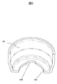
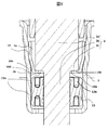
- FIG. 6 is a bird's-eye view of the restriction member 16 of the first embodiment. In Example 1, it is a figure which shows the relationship between the plunger 2 and the control member 16 before a high pressure fuel pump is attached to an engine.
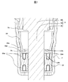
- Example 1 it is a figure which shows the relationship of the plunger 2 and the limitation member 16 after attaching a high pressure fuel pump to an engine.
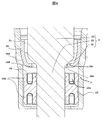
- Example 2 it is a figure which shows the relationship between the plunger 2 and the control member 16 before a high pressure fuel pump is attached to an engine.
- Example 2 it is a figure which shows the relationship of the plunger 2 and the control member 16 after the high pressure fuel pump is attached to an engine.
- FIG. 16 is a bird's-eye view of the restriction member 16 of the third embodiment.
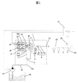
- FIG. 1 shows the overall configuration of the engine system.
- the portion surrounded by a broken line shows the main body of a high pressure fuel pump (hereinafter referred to as a high pressure fuel pump), and the mechanism / parts shown in the broken line show that it is integrally incorporated into the pump body 1 .
- FIG. 1 is a diagram schematically showing the operation of the engine system, and the detailed configuration is different from the configuration of the high pressure fuel pump of FIG.
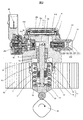
- FIG. 2 shows a longitudinal sectional view of the high pressure fuel pump of the present embodiment
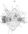
- FIG. 3 is a horizontal sectional view of the high pressure fuel pump as viewed from above.
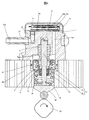
- FIG. 4 is a longitudinal sectional view of the high pressure fuel pump as viewed in a direction different from that of FIG.
- the fuel of the fuel tank 20 is pumped up by a feed pump 21 based on a signal from an engine control unit 27 (hereinafter referred to as an ECU).
- the fuel is pressurized to an appropriate feed pressure and sent through the suction pipe 28 to the low pressure fuel inlet 10a of the high pressure fuel pump.
- the fuel that has passed through the suction joint 51 from the low pressure fuel suction port 10a reaches the suction port 31b of the solenoid valve mechanism 300 that constitutes the capacity variable mechanism through the damper chamber (10b, 10c) in which the pressure pulsation reduction mechanism 9 is disposed.
- the solenoid valve mechanism 300 constitutes a solenoid suction valve mechanism.
- the fuel flowing into the solenoid valve mechanism 300 passes through the suction port opened and closed by the suction valve 30 and flows into the pressure chamber 11.
- a power to reciprocate the plunger 2 is given by the cam mechanism 93 of the engine.
- the reciprocating motion of the plunger 2 sucks the fuel from the suction valve 30 during the downward stroke of the plunger 2 and the fuel is pressurized during the upward stroke.
- the pressurized fuel is pressure-fed through the discharge valve mechanism 8 to the common rail 23 on which the pressure sensor 26 is mounted.
- the injector 24 injects fuel to the engine based on the signal from the ECU 27.
- This embodiment is a high pressure fuel pump applied to a so-called direct injection engine system in which the injector 24 directly injects fuel into the cylinder of the engine.
- the high-pressure fuel pump discharges the desired fuel flow rate of the supplied fuel in response to a signal from the ECU 27 to the solenoid valve mechanism 300.
- the high pressure fuel pump of the present embodiment is closely fixed to the high pressure fuel pump mounting portion 90 of the internal combustion engine.
- screw holes 1b are formed in a mounting flange 1a provided on the pump body 1, and a plurality of bolts (not shown) are inserted into the screw holes 1b.
- the mounting flange 1a is in close contact with and fixed to the high pressure fuel pump mounting portion 90 of the internal combustion engine.
- An O-ring 61 is fitted into the pump body 1 for sealing between the high pressure fuel pump mounting portion 90 and the pump body 1 to prevent engine oil from leaking outside.
- a cylinder 6 is attached to the pump body 1 to guide the reciprocating movement of the plunger 2 and to form a pressure chamber 11 together with the pump body 1. That is, the plunger 2 reciprocates inside the cylinder to change the volume of the pressure chamber.
- a solenoid valve mechanism 300 for supplying fuel to the pressure chamber 11 and a discharge valve mechanism 8 for discharging fuel from the pressure chamber 11 to the discharge passage are provided.
- the cylinder 6 is press-fit with the pump body 1 at its outer peripheral side.
- the pump body 1 is formed with an insertion hole for inserting the cylinder 6 from the lower side, and an inner peripheral convex portion deformed to the inner peripheral side to be in contact with the lower surface of the fixing portion 6a of the cylinder 6 at the lower end of the insertion hole Be done.
- the upper surface of the inner peripheral convex portion of the pump body 1 presses the fixing portion 6a of the cylinder 6 upward in the figure, and the upper end surface of the cylinder 6 is sealed so that the fuel pressurized in the pressurizing chamber 11 does not leak to the low pressure side. ing.
- a tappet 92 which converts the rotational movement of the cam 93 attached to the camshaft of the internal combustion engine into vertical movement and transmits it to the plunger 2.
- the plunger 2 is crimped to the tappet 92 by a spring 4 through a retainer 15. As a result, the plunger 2 can be reciprocated up and down with the rotational movement of the cam 93.
- a plunger seal 13 held at the lower end portion of the inner periphery of the seal holder 7 is installed in a state where the plunger seal 13 slidably contacts the outer periphery of the plunger 2 at the lower portion in the drawing of the cylinder 6.
- the fuel in the sub chamber 7a is sealed to prevent the fuel from flowing into the internal combustion engine.
- lubricating oil including engine oil
- for lubricating sliding parts in the internal combustion engine is prevented from flowing into the inside of the pump body 1.
- a regulating member 16 for preventing the plunger 2 from falling is attached to the upper portion of the plunger seal 13 in a state where the high pressure fuel pump is not attached to the engine.
- the regulating member 16 is made of a metal member and is press-fitted and fixed to the seal holder 7. When the high-pressure fuel pump is not attached to the engine, the plunger 2 moves downward by gravity, but the outer peripheral portion of the large diameter portion 2a comes in contact with the bottom surface of the regulating member 16 to cause the plunger 2 to fall. It is prevented.
- a suction joint 51 is attached to the side surface of the pump body 1 of the high pressure fuel pump.
- the suction joint 51 is connected to a low pressure pipe that supplies fuel from the fuel tank 20 of the vehicle, and the fuel is supplied from here to the inside of the high pressure fuel pump.
- the suction filter 52 has a function of preventing foreign matter present between the fuel tank 20 and the low pressure fuel suction port 10a from being absorbed by the flow of fuel into the high pressure fuel pump.
- the fuel that has passed through the low pressure fuel suction port 10a travels to the pressure pulsation reducing mechanism 9 through the low pressure fuel suction passage vertically connected to the pump body 1 shown in FIG.
- the pressure pulsation reducing mechanism 9 is disposed in the damper chamber (10b, 10c) between the damper cover 14 and the upper end surface of the pump body 1, and is supported from the lower side by a holding member 9a disposed on the upper end surface of the pump body 1.
- Ru Specifically, the pressure pulsation reducing mechanism 9 is a metal damper configured by overlapping two metal diaphragms. A gas of 0.3 MPa to 0.6 MPa is enclosed inside the pressure pulsation reducing mechanism 9, and the outer peripheral edge portion is fixed by welding.
- Damper chambers (10b, 10c) communicating with the low pressure fuel suction port 10a and the low pressure fuel suction passage are formed on upper and lower surfaces of the pressure pulsation reducing mechanism 9, respectively.
- the holding member 9a is formed with a passage communicating the upper side and the lower side of the pressure pulsation reducing mechanism 9.
- the suction port 31 b is formed in communication with the suction valve seat member 31 forming the suction valve seat 31 a in the vertical direction.
- the terminal 46 is molded integrally with the connector so that the other end can be connected to the engine control unit side.
- the solenoid valve mechanism 300 will be described with reference to FIG.
- the plunger 2 moves in the direction of the cam 93 and is in the suction stroke state by the rotation of the cam 93, the volume of the pressurizing chamber 11 increases and the fuel pressure in the pressurizing chamber 11 decreases.
- the suction valve 30 is opened.
- the suction valve 30 contacts the stopper 32.
- the opening formed in the suction valve seat member 31 opens and opens. The fuel passes through the opening of the suction valve sheet member 31 and flows into the pressurizing chamber 11 through a hole formed in the pump body 1 in the lateral direction.
- the rod biasing spring 40 biases the rod convex portion 35a which is convex on the outer diameter side of the rod 35, and is set to have a biasing force necessary and sufficient to open the suction valve 30 in the non-energized state.
- the volume of the pressure chamber 11 decreases with the upward movement of the plunger 2. In this state, the fuel once sucked into the pressure chamber 11 passes through the opening of the suction valve 30 in the open state again through the suction passage. Since the pressure is returned to 10d, the pressure in the pressure chamber does not rise. This process is called a return process.
- the suction valve 30 is closed by the biasing force of the suction valve biasing spring 33 and the fluid force caused by the fuel flowing into the suction passage 10d.
- the fuel pressure in the pressure chamber 11 rises with the upward movement of the plunger 2, and when the pressure in the fuel outlet 12 becomes higher than that, the high pressure fuel is discharged through the discharge valve mechanism 8 to the common rail 23. Supplied. This stroke is called a discharge stroke.
- the upward stroke from the lower start point to the upper start point of the plunger 2 consists of a return stroke and a discharge stroke. Then, by controlling the energization timing of the coil 43 of the solenoid valve mechanism 300, it is possible to control the amount of high pressure fuel to be discharged.
- the plunger 2 has a large diameter portion 2a and a small diameter portion 2b, and the volume of the sub chamber 7a is increased or decreased by the reciprocating movement of the plunger.
- the sub chamber 7a is in communication with the damper chamber (10b, 10c) by the fuel passage 10e.
- the flow rate of fuel into and out of the pump in the suction stroke or return stroke of the pump can be reduced, and the pressure pulsation generated inside the high pressure fuel pump can be reduced.
- the discharge valve mechanism 8 is provided at the outlet of the pressure chamber 11.
- the discharge valve mechanism 8 comprises a discharge valve seat 8a, a discharge valve 8b contacting and separating with the discharge valve seat 8a, and a discharge valve 8b.
- the discharge valve spring 8c is biased toward the seat 8a, and the discharge valve stopper 8d determines the stroke (moving distance) of the discharge valve 8b.
- the discharge valve stopper 8d and the pump body 1 are joined by welding at the contact portion 8e to block the fuel from the outside.
- the discharge valve 8b In the state where there is no fuel pressure difference between the pressurizing chamber 11 and the discharge valve chamber 12a, the discharge valve 8b is crimped to the discharge valve seat 8a by the biasing force of the discharge valve spring 8c and is in a closed state.
- the discharge valve 8b opens against the discharge valve spring 8c.
- the high pressure fuel in the pressure chamber 11 is discharged to the common rail 23 through the discharge valve chamber 12 a, the fuel discharge passage 12 b, and the fuel discharge port 12.
- the discharge valve 8 b When the discharge valve 8 b is opened, the discharge valve 8 b contacts the discharge valve stopper 8 d and the stroke is limited. Therefore, the stroke of the discharge valve 8b is appropriately determined by the discharge valve stopper 8d. As a result, the stroke is too large, and it is possible to prevent the fuel discharged to a high pressure into the discharge valve chamber 12a from flowing back into the pressure chamber 11 again due to the delay of closing the discharge valve 8b. Can be suppressed.
- the discharge valve 8 b When the fuel in the pressure chamber 11 is pressurized and the discharge valve 8 b is opened, the high pressure fuel in the pressure chamber 11 is discharged from the fuel discharge port 12 through the discharge valve chamber 80 and the fuel discharge passage.
- the fuel discharge port 12 is formed in a discharge joint 60, and the discharge joint 60 is welded and fixed to the pump body 1 at a welding portion to secure a fuel passage.
- the relief valve mechanism 200 includes a relief body 201, a relief valve 202, a relief valve holder 203, a relief spring 204, and a spring stopper 205.
- the relief body 201 is provided with a tapered seat portion. The load of the relief spring 204 is loaded through the valve holder 203, and the valve 202 is pressed against the seat portion of the relief body 201 and cooperates with the seat portion to shut off the fuel.
- the pressure of the fuel discharge port 12 becomes abnormally high pressure due to a failure of the electromagnetic suction valve 300 of the high pressure fuel pump, etc. and becomes larger than the set pressure of the relief valve mechanism 200, the abnormally high pressure fuel is on the low pressure side via the relief passage 213
- the damper chamber 10c is relieved.
- the relief destination of the relief valve mechanism 200 is the damper chamber 10 b, the relief chamber may be configured to relieve the pressure chamber 11.
- FIG. 5 is a bird's-eye view of the regulating member 16.
- FIG. 6 is a view showing the relationship between the plunger 2 and the regulating member 16 before the high pressure fuel pump is attached to the engine. Before the high pressure fuel pump is attached to the engine, the biasing force of the biasing spring 4 of FIG. 4 moves the plunger 2 downward, but the outer peripheral portion 2c of the large diameter portion 2a of the plunger 2 It is supported in contact with
- FIG. 7 is a view showing the relationship between the plunger 2 and the restricting member 16 after the high pressure fuel pump is attached to the engine.
- the plunger 2 since an upward biasing force is applied by the biasing spring 4 of FIG. 4, the plunger 2 is biased upward by the biasing spring 4 via the retainer 15. Therefore, after being attached to the engine, the plunger 2 is driven in the vertical direction without coming into contact with the bottom surface 16 c of the regulating member 16.
- the seal portion 13 prevents the fuel in the high pressure fuel pump from flowing into the engine, or the oil in the engine from flowing into the high pressure fuel pump.
- the seal portion 13 has a spring 13a which radially extends in the upper and lower portions. As a result, the seal portion 13 is held with the seal holder 7 by the radial tension generated by the spring 13a.
- a recess 13b is formed in the entire circumferential direction on the radially outer side of the small diameter portion 2b, which is recessed from the opposite surface (upper surface) facing the sub chamber 7b to the opposite side (lower side) to the sub chamber 7b.
- a frictional force is also generated between the seal portion 13 and the small diameter portion 2b of the plunger 2 due to the radial tension generated by the spring 13a.
- the average pressure by the feed pump 21 is loaded on the seal portion 13, and the seal portion 13 is pressed downward in FIG. Even if a frictional force is generated between the seal portion 13 and the small diameter portion 2 b of the plunger 2, the seal portion 13 may be pressed against the bottom surface of the seal holder 7.
- the plunger 2 Before the high pressure fuel pump is attached to the engine head, the plunger 2 is pushed downward in FIG. 6 or 7 by the biasing spring 4. At that time, the outer peripheral portion 2 c of the large diameter portion 2 a of the plunger 2 is in direct contact with the seal portion 13, which may damage the seal portion 13. Therefore, a regulating member 16 is provided as a protective member for the seal portion 13. As a result, in the seal portion 13, the outer peripheral portion 2c of the large diameter portion 2a of the plunger 2 comes into contact with the bottom surface 16c of the regulating member 16, and the further downward movement is regulated. For this reason, the seal part 13 can be protected.
- the outer peripheral portion 2c connecting the large diameter portion 2a and the small diameter portion 2b is formed in a plane perpendicular to the plunger axial direction. According to this configuration, since the contact surface with the opposing surface 16c (regulating portion) can be sufficiently secured on a plane, the reliability is improved. Therefore, it is possible to easily realize both the protection function of the seal portion 13 before mounting the engine of the high pressure fuel pump and the cooling function at the time of driving.
- the regulating member 16 is preferably made of a metal member and manufactured by press molding. This enables mass production at low cost.
- the lower side (pump outer side) of the seal portion 13 is exposed to oil. Since the seal portion 13 is a resin material, changes in fuel temperature and oil temperature affect the strength reduction of the seal portion 13. Further, the temperature of the seal portion 13 is also raised by the sliding heat generated by the plunger 2 sliding up and down. Basically, the strength decreases as the temperature of the seal portion 13 becomes higher. Therefore, it is necessary to provide a space between the regulating member 16 and the seal portion 13 for circulating the fuel having a temperature lower than that of the oil on the upper side (pump inner side) of the seal portion 13 exposed to the fuel. It is desirable that the length of the space in the plunger axial direction be greater than, for example, the metal thickness of the regulating member 16. By doing so, the seal portion 13 can be cooled by the fuel. It is important to ensure the space between the regulating member 16 and the seal portion 13 and to cool the seal portion 13.
- the high pressure fuel pump of the present embodiment includes the plunger 2 having the large diameter portion 2a and the small diameter portion 2b, the pressurizing chamber 11 whose volume is increased and decreased by the reciprocating movement of the plunger 2, and the outer periphery of the small diameter portion 2b of the plunger 2
- a seal portion (plunger seal 13) is provided which is disposed on the side and seals between the outer peripheral space (sub chamber 7a) of the small diameter portion 2b of the plunger 2 and the external space (engine side space).
- the restricting member 16 is disposed between the seal portion 13 and the lower surface 2 c of the large diameter portion 2 a of the plunger 2 and restricts the movement of the large diameter portion 2 a of the plunger 2 to the opposite side to the pressure chamber 11.
- the regulating member 16 has an opposing surface 16c opposed to the lower surface 2c of the large diameter portion 2a, and a clearance 16e is formed between the innermost peripheral portion of the opposing surface 16c and the small diameter portion 2b.
- a communication passage 16d is formed, which communicates the upper space (sub chamber 7a) of the facing surface 16c and the lower space 7b.
- the fuel circulation state around the seal portion 13 can be improved, and the heat generated by the friction between the small diameter portion 2 b of the plunger 2 and the seal portion 13 is released to sufficiently cool the seal portion 13. It is possible to obtain a high pressure fuel pump which does not exceed the allowable temperature.
- the communication passage 16d is formed of a notch formed so as to be recessed radially outward from the innermost circumferential portion (inner circumferential portion of the gap portion 16e) of the regulating member 16. Further, it is preferable that the communication passage 16d be formed at a position overlapping the connecting portion (the outer peripheral portion 2c) between the large diameter portion 2a and the small diameter portion 2b when viewed from the plunger axial direction. Since the fuel moves up and down by the connecting portion (the outer peripheral portion 2c), the communication passage 16d is formed to overlap the upper and lower spaces (the sub chamber 7a) and the lower space 7b. The amount of fuel can be increased, and the cooling effect of the seal portion 13 can be further improved.
- the regulating member 16 has an inclined portion 16 a inclined at the middle portion, and the inclined portion 16 a is axially restricted and held by contacting with the inclined portion of the seal holder 7. Further, the length from the innermost peripheral portion (inner peripheral portion of the gap portion 16e) to the outermost peripheral portion of the communication passage 16d is the length between the small diameter portion 2b and the innermost peripheral portion (inner peripheral portion of the gap portion 16e) It is desirable to form the communication passage 16d so as to be longer than the end.
- the outermost peripheral portion of the communication passage 16d is configured to overlap with the concave portion 13b which is concave on the opposite side of the upper space 7a of the seal portion 13 in the plunger axial direction.
- the communication passages 16d be formed at equal intervals in the circumferential direction as viewed from the plunger axial direction. This makes it possible to secure the transfer of fuel required for cooling.
- a suction valve 30 for opening and closing the flow path is provided on the upstream side of the pressurizing chamber 11, and the upper space (subchamber 7 a) of the opposing surface 16 c is a low pressure space on the upstream side of the suction valve 30. It communicates with 10c. And, by the reciprocating motion of the plunger 2, the fuel is configured to move back and forth between the low pressure space 10c and the upper space (sub chamber 7a) of the facing surface 16c.
- the restricting member 16 is formed of a cylindrical metal member, and the opposing surface 16 c is formed of a bottom surface 16 c disposed to face the outer peripheral portion 2 c of the large diameter portion 2 a of the plunger 2.
- the seal holder 7 holds the seal portion 13 and forms an outer peripheral space (sub chamber 7 a) of the small diameter portion 2 b.
- the seal holder 7 is fixed to the pump body 1 forming the pressure chamber 11 and configured to support the restriction member 16 in the plunger axial direction on the inner peripheral side.
- the problem to be solved in the present embodiment is remarkable particularly when the difference in diameter between the large diameter portion 2a and the small diameter portion 2b is small. This is because the inner diameter of the restricting portion of the seal holder 15 needs to be smaller than the large diameter portion 2a of the plunger and larger than the small diameter portion 2b. Therefore, in terms of geometrical structure, the seal portion protecting function of the small diameter portion 2b of the plunger and the seal holder 15 This is because the gap between the (stopper) portions is reduced.
- the above effect is particularly effective when a large difference in diameter between the large diameter portion 2a and the small diameter portion 2b of the plunger 2 can be secured.
- the diameter of the large diameter portion 2a of the plunger is 10 mm and the diameter of the small diameter portion is 6 mm, for example, the difference in diameter is 4 mm, and 2 mm can be secured as the height of the step 2c.
- 1 mm of clearances between the seal part 13 and the regulation member 16 is secured, the cooling effect of the seal part is sufficient, and the area of the stopper FIG.
- the difference in diameter between the large diameter portion 2a and the small diameter portion 2b of the plunger 2 is small, the situation is different.
- the diameter of the large diameter portion 2a of the plunger is 8 mm and the diameter of the small diameter portion is 6 mm, the difference in diameter is 2 mm.
- the height of the step 2c is 1 mm.
- the clearance between the seal portion 13 and the restriction member 16 must be about 0.5 mm in median value in consideration of tolerances and the like. Then, the cooling function of the above-mentioned seal part becomes insufficient, and there is a problem that high temperature and strength of the seal part 13 become insufficient, leading to breakage.
- the missing portion 16 d is provided on the facing surface 16 c (regulating portion) of the regulating member 16.
- the missing portion 16 d plays the same role as the clearance between the seal portion 13 and the regulating member 16, sufficiently securing the cooling effect of the seal portion 13, and the opposing surface 16 c (regulating portion) Can also be provided.
- the regulating member 16 can be manufactured by press molding, and mass production can be performed at low cost.
- FIG. 8 and 9 show a second embodiment of the present invention.
- FIG. 8 is a view showing the relationship between the plunger 2 and the regulating member 16 before the high pressure fuel pump is attached to the engine.
- FIG. 9 is a view showing the relationship between the plunger 2 and the restricting member 16 after the high pressure fuel pump is attached to the engine.
- the outer peripheral portion 2c connecting the large diameter portion 2a and the small diameter portion 2b is formed in a plane perpendicular to the plunger axial direction, but in the present embodiment, it is an inclined surface inclined with respect to the plunger axial direction (A tapered surface).
- the other configuration is the same as that of the first embodiment, and thus the detailed description is omitted.
- the restricting member 16 and the seal holder 7 can be press-molded as in the first embodiment.
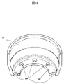
- FIG. 10 shows a regulating member 16 according to a third embodiment of the present invention.
- the portion of the regulating member 16 is the same as that of the first embodiment or the second embodiment, and thus the description thereof is omitted.
- a plurality of communication holes 16f are provided.
- the communication hole 16f does not communicate with the gap 16e.
- the restricting portion 16c contacts the step portion 2c of the plunger 2 and is protected without contacting the seal portion 13. That is, the communication passage 16 f is formed by a communication hole formed at a position radially outward of the innermost circumferential portion (inner circumferential portion of the gap portion 16 e) of the regulating member 16.
- the seal portion 13 can be cooled by the fuel. As a result, it is possible to obtain a high-pressure fuel pump in which the seal portion 13 does not become hot and break.
Landscapes
- Engineering & Computer Science (AREA)
- Chemical & Material Sciences (AREA)
- Combustion & Propulsion (AREA)
- Mechanical Engineering (AREA)
- General Engineering & Computer Science (AREA)
- Fuel-Injection Apparatus (AREA)
Abstract
Description
シール部13により、シール室10f中の燃料がタペット3側にあるエンジンの内部に流入することを防止する。同時にエンジンルーム内の摺動部を潤滑する潤滑油(エンジンオイルも含む)がポンプ本体1の内部に流入するのを防止する。」と開示されている(段落0078、0079参照)。
リリーフ弁機構200はリリーフボディ201、リリーフ弁202、リリーフ弁ホルダ203、リリーフばね204、ばねストッパ205からなる。リリーフボディ201には、テーパー形状のシート部が設けられている。バルブ202はリリーフばね204の荷重がバルブホルダ203を介して負荷され、リリーフボディ201のシート部に押圧され、シート部と協働して燃料を遮断している。
図5は、規制部材16の鳥瞰図である。
図6は、高圧燃料ポンプがエンジンに取り付けられる前におけるプランジャ2と規制部材16との関係を示す図である。高圧燃料ポンプがエンジンに取り付けられる前においては図4の付勢ばね4の付勢力によりプランジャ2が下方向に移動するが、プランジャ2の大径部2aの外周部2cが規制部材16の底面16cと接触して支持されている。
図8は、高圧燃料ポンプがエンジンに取り付けられる前におけるプランジャ2と規制部材16との関係を示す図である。
図9は、高圧燃料ポンプがエンジンに取り付けられた後におけるプランジャ2と規制部材16との関係を示す図である。
Claims (10)
- 大径部と小径部とを有するプランジャと、
前記プランジャの往復運動により体積が増減する加圧室と、
前記プランジャの前記小径部の外周側に配置され、前記プランジャの前記小径部の外周側空間と外部空間との間をシールするシール部と、
前記シール部と前記プランジャの前記大径部の下面との間に配置され、前記プランジャの前記大径部の前記加圧室と反対側への移動を規制する規制部材と、を備えた高圧燃料ポンプにおいて、
前記規制部材は、前記大径部の前記下面と対向する対向面を有し、かつ前記対向面の最内周部と前記小径部との間には隙間部が形成され、さらに前記隙間部以外に前記対向面の上側空間と下側空間とを連通する連通路が形成されたことを特徴とする高圧燃料ポンプ。 - 請求項1に記載の高圧燃料ポンプにおいて、
前記連通路は前記規制部材の前記最内周部から径方向外側に凹むように形成された切欠き部により構成されたことを特徴とする高圧燃料ポンプ。 - 請求項1に記載の高圧燃料ポンプにおいて、
前記連通路は前記規制部材の前記最内周部に対して径方向外側の位置に形成された連通穴により構成されたことを特徴とする高圧燃料ポンプ。 - 請求項1~3の何れかに記載の高圧燃料ポンプにおいて、
プランジャ軸方向から見て、前記連通路は、前記大径部と前記小径部との間の連結部と重なる位置に形成されたことを特徴とする高圧燃料ポンプ。 - 請求項1に記載の高圧燃料ポンプにおいて、
前記連通路はプランジャ軸方向から見て、複数、周方向において等間隔に形成されたことを特徴とする高圧燃料ポンプ。 - 請求項1に記載の高圧燃料ポンプにおいて、
前記加圧室の上流側には流路を開閉する吸入弁を備え、
前記対向面の前記上側空間は前記吸入弁の上流側の低圧空間と連通し、前記プランジャの往復運動により、燃料が前記低圧空間と前記対向面の前記上側空間とを行き来するように構成されたことを特徴とする高圧燃料ポンプ。 - 請求項1に記載の高圧燃料ポンプにおいて、
前記規制部材は円筒形状の金属部材で構成され、
前記対向面は前記プランジャの前記大径部と対向するように配置される底面で構成されたことを特徴とする高圧燃料ポンプ。 - 請求項1に記載の高圧燃料ポンプにおいて、
前記シール部を保持するとともに前記小径部の前記外周側空間を形成するシールホルダを備え、
前記シールホルダは、前記加圧室を形成するポンプボディに固定され、かつ、内周側で前記規制部材をプランジャ軸方向に支持するように構成されたことを特徴とする高圧燃料ポンプ。 - 請求項1に記載の高圧燃料ポンプにおいて、
前記隙間部の最内周部から前記連通路の最外周部までの長さが、前記小径部と前記隙間部の内周部との間の長さよりも長くなるように前記連通路が形成されたことを特徴とする高圧燃料ポンプ。 - 請求項1に記載の高圧燃料ポンプにおいて、
プランジャ軸方向において前記連通路の最外周部が前記シール部の前記上側空間と反対側に凹む凹み部と重なるように構成されたことを特徴とする高圧燃料ポンプ。
Priority Applications (3)
| Application Number | Priority Date | Filing Date | Title |
|---|---|---|---|
| CN201880044000.8A CN110832187B (zh) | 2017-07-14 | 2018-06-28 | 高压燃料泵 |
| JP2019529047A JP6851481B2 (ja) | 2017-07-14 | 2018-06-28 | 高圧燃料ポンプ |
| DE112018002953.0T DE112018002953B4 (de) | 2017-07-14 | 2018-06-28 | Hochdruckkraftstoffpumpe |
Applications Claiming Priority (2)
| Application Number | Priority Date | Filing Date | Title |
|---|---|---|---|
| JP2017137640 | 2017-07-14 | ||
| JP2017-137640 | 2017-07-14 |
Publications (1)
| Publication Number | Publication Date |
|---|---|
| WO2019012998A1 true WO2019012998A1 (ja) | 2019-01-17 |
Family
ID=65001262
Family Applications (1)
| Application Number | Title | Priority Date | Filing Date |
|---|---|---|---|
| PCT/JP2018/024509 Ceased WO2019012998A1 (ja) | 2017-07-14 | 2018-06-28 | 高圧燃料ポンプ |
Country Status (4)
| Country | Link |
|---|---|
| JP (1) | JP6851481B2 (ja) |
| CN (1) | CN110832187B (ja) |
| DE (1) | DE112018002953B4 (ja) |
| WO (1) | WO2019012998A1 (ja) |
Cited By (1)
| Publication number | Priority date | Publication date | Assignee | Title |
|---|---|---|---|---|
| JP2024522883A (ja) * | 2021-07-05 | 2024-06-21 | ロベルト・ボッシュ・ゲゼルシャフト・ミト・ベシュレンクテル・ハフツング | ポンプ、特に燃料噴射ポンプ |
Citations (3)
| Publication number | Priority date | Publication date | Assignee | Title |
|---|---|---|---|---|
| JP2010106741A (ja) * | 2008-10-30 | 2010-05-13 | Hitachi Automotive Systems Ltd | 高圧燃料ポンプ |
| JP2014077361A (ja) * | 2012-10-09 | 2014-05-01 | Denso Corp | 高圧ポンプ |
| JP2015055231A (ja) * | 2013-09-13 | 2015-03-23 | 株式会社デンソー | 高圧ポンプ |
Family Cites Families (9)
| Publication number | Priority date | Publication date | Assignee | Title |
|---|---|---|---|---|
| DE102006055298A1 (de) * | 2006-11-23 | 2008-06-05 | Elringklinger Ag | Dichtungsanordnung |
| JP5244761B2 (ja) * | 2009-10-06 | 2013-07-24 | 日立オートモティブシステムズ株式会社 | 高圧燃料供給ポンプ |
| JP5418488B2 (ja) * | 2010-12-16 | 2014-02-19 | 株式会社デンソー | 高圧ポンプ |
| DE102014225319A1 (de) * | 2014-12-09 | 2016-06-09 | Robert Bosch Gmbh | Kraftstoff-Hochdruckpumpe mit einem Kolben |
| CN105863916A (zh) * | 2015-01-16 | 2016-08-17 | 罗伯特·博世有限公司 | 高压燃料泵 |
| JP6235518B2 (ja) * | 2015-03-31 | 2017-11-22 | 日立オートモティブシステムズ株式会社 | 高圧燃料供給ポンプ及び高圧燃料供給ポンプの組立て方法 |
| JP6151399B2 (ja) * | 2016-03-28 | 2017-06-21 | 日立オートモティブシステムズ株式会社 | 高圧燃料供給ポンプ |
| CN205936934U (zh) * | 2016-08-29 | 2017-02-08 | 浙江巴腾动力系统有限公司 | 发动机喷油泵 |
| CN106150810A (zh) * | 2016-08-29 | 2016-11-23 | 温州巴腾电子科技有限公司 | 一种发动机喷油泵 |
-
2018
- 2018-06-28 CN CN201880044000.8A patent/CN110832187B/zh active Active
- 2018-06-28 DE DE112018002953.0T patent/DE112018002953B4/de active Active
- 2018-06-28 JP JP2019529047A patent/JP6851481B2/ja active Active
- 2018-06-28 WO PCT/JP2018/024509 patent/WO2019012998A1/ja not_active Ceased
Patent Citations (3)
| Publication number | Priority date | Publication date | Assignee | Title |
|---|---|---|---|---|
| JP2010106741A (ja) * | 2008-10-30 | 2010-05-13 | Hitachi Automotive Systems Ltd | 高圧燃料ポンプ |
| JP2014077361A (ja) * | 2012-10-09 | 2014-05-01 | Denso Corp | 高圧ポンプ |
| JP2015055231A (ja) * | 2013-09-13 | 2015-03-23 | 株式会社デンソー | 高圧ポンプ |
Cited By (2)
| Publication number | Priority date | Publication date | Assignee | Title |
|---|---|---|---|---|
| JP2024522883A (ja) * | 2021-07-05 | 2024-06-21 | ロベルト・ボッシュ・ゲゼルシャフト・ミト・ベシュレンクテル・ハフツング | ポンプ、特に燃料噴射ポンプ |
| JP7612058B2 (ja) | 2021-07-05 | 2025-01-10 | ロベルト・ボッシュ・ゲゼルシャフト・ミト・ベシュレンクテル・ハフツング | ポンプ、特に燃料噴射ポンプ |
Also Published As
| Publication number | Publication date |
|---|---|
| JP6851481B2 (ja) | 2021-03-31 |
| DE112018002953B4 (de) | 2025-10-02 |
| JPWO2019012998A1 (ja) | 2020-03-26 |
| DE112018002953T5 (de) | 2020-03-05 |
| CN110832187B (zh) | 2021-09-21 |
| CN110832187A (zh) | 2020-02-21 |
Similar Documents
| Publication | Publication Date | Title |
|---|---|---|
| US20150078922A1 (en) | High pressure pump | |
| WO2010050569A1 (ja) | 高圧燃料供給ポンプ | |
| CN111322187B (zh) | 高压燃料供给泵 | |
| EP3543519B1 (en) | High-pressure fuel supply pump | |
| EP3653867B1 (en) | High-pressure fuel pump | |
| JP5244761B2 (ja) | 高圧燃料供給ポンプ | |
| US20200284229A1 (en) | High-pressure fuel supply pump | |
| JP6851481B2 (ja) | 高圧燃料ポンプ | |
| CN112840119B (zh) | 高压燃料泵 | |
| WO2016103945A1 (ja) | バルブ機構、及びこれを備えた高圧燃料供給ポンプ | |
| JPWO2015163243A1 (ja) | 高圧燃料供給ポンプ | |
| JP2020133490A (ja) | 高圧燃料供給ポンプ及びリリーフ弁機構 | |
| JP2019100268A (ja) | 燃料供給ポンプ | |
| JP2019090365A (ja) | 燃料供給ポンプ | |
| JP2018119479A (ja) | 高圧燃料ポンプ | |
| CN110809670B (zh) | 电磁吸入阀以及具备该电磁吸入阀的高压燃料泵 | |
| JP6952191B2 (ja) | 燃料ポンプ | |
| JP6596542B2 (ja) | バルブ機構及びこれを備えた高圧燃料供給ポンプ | |
| CN111989481B (zh) | 燃料供给泵以及燃料供给泵的制造方法 | |
| JP2019090366A (ja) | リリーフ弁機構およびこれを備えた燃料供給ポンプ | |
| JP6385840B2 (ja) | バルブ機構及びこれを備えた高圧燃料供給ポンプ | |
| JP2018178969A (ja) | 高圧燃料供給ポンプ | |
| JP2019027334A (ja) | 高圧燃料供給ポンプ |
Legal Events
| Date | Code | Title | Description |
|---|---|---|---|
| 121 | Ep: the epo has been informed by wipo that ep was designated in this application |
Ref document number: 18831890 Country of ref document: EP Kind code of ref document: A1 |
|
| ENP | Entry into the national phase |
Ref document number: 2019529047 Country of ref document: JP Kind code of ref document: A |
|
| WWP | Wipo information: published in national office |
Ref document number: 112018002953 Country of ref document: DE |
|
| 122 | Ep: pct application non-entry in european phase |
Ref document number: 18831890 Country of ref document: EP Kind code of ref document: A1 |
|
| WWG | Wipo information: grant in national office |
Ref document number: 112018002953 Country of ref document: DE |